Design of a Fast Servo Multi-Element Feed Drive
10
Design of a Fast Servo Multi-Element Feed Drive A. T. Elfizy McMaster Manufacturing Research Institute (MMRI) McMaster University [email protected] M.A. Elbestawi McMaster Manufacturing Research Institute (MMRI) McMaster University [email protected] Abstract High precision positioning has become one of the most important features of a precision machine. Such a machine is required to provide versatility, speed and workspace and high precision positioning. Combining coarse (large stroke) and fine (high resolution) drive elements, connected in series, in a multi-element feed drive system provides the capacity of a large workspace with the property of high resolution motion. The performance of the whole system may be improved by adopting the merits of both drive elements to work in a complementary fashion. The multi-element feed drive concept has several applications in manufacturing, robotics and data storage. Fast tool servo in manufacturing is a direct use of the concept and its applications range from the creation of asymmetric surfaces to online chatter suppression. Micro-macro robots are also examples of multi-element feed drive systems that provide advantages when both large work space and accurate end-effector positioning are required. This paper presents an innovative design of a multi-element feed drive system for machine tools. It studies the design methodology and the implementation of the system and investigates several considerations that govern the design process and determine the performance. A multi-element feed drive setup based on a combination of PA and LM was built for experimental testing. Results show that the multi-element feed drive is able to improve the tracking performance as well as the steady state error. It also achieves faster settling time. 1. Introduction High precision positioning is one of the most important features of a precision machine [1]. Such a machine is required to provide versatility, speed and workspace as well as high precision positioning. Combining coarse (large stroke) and fine (high resolution) drive elements, connected in series, to create a multi-element feed drive (MEFD) provides the capacity of a large workspace with the property of high precision motion [2]. The MEFD concept has several applications in manufacturing, robotics and data storage. The majority of MEFD applications are in hard disks. The industry continues to strive for increased real storage densities and reduced data access times. This necessitate performance improvements of the head positioning system in terms of fast transition from one track to another (track seeking), fast and accurate settling (settling), and precise track following of the target track. To meet these requirements, the servo bandwidth of the head positioning system must be increased to lower the sensitivity to disturbances such as disk flutter vibrations, spindle motor run-out, windage, and external vibration. The servo bandwidth, however, is mainly limited by the mechanical resonance of the head positioning mechanism. Several MEFDs have been developed that can increase the servo bandwidth [3] – [7]. Micro-macro robots are another example of MEFDs that provide advantages when both large work space and precise end-effector positioning are required [8]. The parallel coupled micro-macro robot system, described in [9], exhibits superior characteristics when compared to typical single actuator robot systems. The benefits of this system are improved small signal force control bandwidth, reduced impedance, reduced distortion, reduced impact forces, improved small signal position bandwidth, improved force resolution and dynamic range. A Fast tool servo for machining is a direct use of the concept and its applications range from the creation of asymmetric surfaces to online chatter suppression [10]. Fast tool servos have been applied to the diamond turning of brittle materials, [11], where the metal removal rate has to be kept in the material
Transcript of Design of a Fast Servo Multi-Element Feed Drive
Design of a Fast Servo Multi-Element Feed Drive
A. T. Elfizy McMaster Manufacturing Research Institute
(MMRI) McMaster University
M.A. Elbestawi McMaster Manufacturing Research Institute
(MMRI) McMaster University
Abstract
High precision positioning has become one of the most important features of a precision machine. Such a machine is required to provide versatility, speed and workspace and high precision positioning. Combining coarse (large stroke) and fine (high resolution) drive elements, connected in series, in a multi-element feed drive system provides the capacity of a large workspace with the property of high resolution motion. The performance of the whole system may be improved by adopting the merits of both drive elements to work in a complementary fashion. The multi-element feed drive concept has several applications in manufacturing, robotics and data storage. Fast tool servo in manufacturing is a direct use of the concept and its applications range from the creation of asymmetric surfaces to online chatter suppression. Micro-macro robots are also examples of multi-element feed drive systems that provide advantages when both large work space and accurate end-effector positioning are required. This paper presents an innovative design of a multi-element feed drive system for machine tools. It studies the design methodology and the implementation of the system and investigates several considerations that govern the design process and determine the performance. A multi-element feed drive setup based on a combination of PA and LM was built for experimental testing. Results show that the multi-element feed drive is able to improve the tracking performance as well as the steady state error. It also achieves faster settling time. 1. Introduction High precision positioning is one of the most important features of a precision machine [1]. Such a machine is required to provide versatility, speed and workspace as well as high precision positioning.
Combining coarse (large stroke) and fine (high resolution) drive elements, connected in series, to create a multi-element feed drive (MEFD) provides the capacity of a large workspace with the property of high precision motion [2]. The MEFD concept has several applications in manufacturing, robotics and data storage. The majority of MEFD applications are in hard disks. The industry continues to strive for increased real storage densities and reduced data access times. This necessitate performance improvements of the head positioning system in terms of fast transition from one track to another (track seeking), fast and accurate settling (settling), and precise track following of the target track. To meet these requirements, the servo bandwidth of the head positioning system must be increased to lower the sensitivity to disturbances such as disk flutter vibrations, spindle motor run-out, windage, and external vibration. The servo bandwidth, however, is mainly limited by the mechanical resonance of the head positioning mechanism. Several MEFDs have been developed that can increase the servo bandwidth [3] – [7]. Micro-macro robots are another example of MEFDs that provide advantages when both large work space and precise end-effector positioning are required [8]. The parallel coupled micro-macro robot system, described in [9], exhibits superior characteristics when compared to typical single actuator robot systems. The benefits of this system are improved small signal force control bandwidth, reduced impedance, reduced distortion, reduced impact forces, improved small signal position bandwidth, improved force resolution and dynamic range. A Fast tool servo for machining is a direct use of the concept and its applications range from the creation of asymmetric surfaces to online chatter suppression [10]. Fast tool servos have been applied to the diamond turning of brittle materials, [11], where the metal removal rate has to be kept in the material
ductile zone to achieve high surface finish. Brittle materials such as glass, ceramics and germanium have considerable research applications in optics and precision engineering systems. Fast tool servos provide an independently operated positioning device that has a high bandwidth and accuracy compared to a conventional ball screw drive. Because machine tools are traditionally massive, the inertia involved makes high-speed actuation of the slide ways impractical [12]. Using a fast tool servo as a secondary actuation device in the direction of interest should improve the overall performance of the machine tool. Fast tool servos also can be used to correct machine related errors such as spindle errors and parasitic vibrations [13]. They have also been widely used for the creation of asymmetric surfaces on a component, such as mirrors, anamorphic optics, and generalized surfaces, [10] and [13]. The only published applications of fast tool servos have been with turning. Fast tool servos are also typically controlled independently of the original drive. This paper presents the design and implementation of MEFDs for machine tools. Unlike fast tool servos, the proposed designs are for the entire feed drive rather than an addition to it. This has the advantage of allowing us to design the controller such that the two drives work together in a complementary fashion. The paper is organized as follows. The first section gave the motivation for the work and a general background. Section two explains the limitations of single element feed drives for precision positioning. Section three introduces the issues involved in the design of a MEFD. Section four presents the design and implementation of a single axis MEFD system. In section five the design for a two-axis MEFD is described. Section six presents experimental results with a MEFD while performing metal cutting. Section seven concludes the paper. 2. Limitations of single element feed drives Ball screw drives are dominant as feed drives but several limitations are associated with them. Pritschow and Philipp, in [15] and [16], and Pritschow in [17], summarized conventional ball screw feed drive limits of performance to be: transmission errors, dead zone, backlash, elasticities, large inertia, and wear. Ball screw feed drives are limited also dynamically by their low first natural frequency. This represents a major drawback for high precision systems, where the feed drive has to show high dynamic stiffness against external excitations. LMs represent a good choice for high precision feed drives. They are systems with higher natural frequencies and higher stiffness because there are no
elasticities involved. However, LMs possess some limitations when it comes to submicron positioning. Force ripple in LMs [18], stick-slip friction and quantization error could affect the accuracy, especially with high resolution positioning. Positioning systems based on PAs have received increased attention recently in many high precision applications. They have advantages that include: unlimited resolution, large force, fast expansion and no magnetic effects [19]. Their nano-resolution makes PAs suitable for applications that require high accuracy and nano-resolution positioning such as: - Precision machining in metals, optics, laser cutting and diamond turning. - Metrology, laser systems and optical inspection. - Micro-manufacturing, assembly and testing. - Telecommunication, photonics, fiber optics and fiber alignment. - Microscopy. - Data storage. - Semiconductor, LCD and flat panel manufacturing. - Medical technology. - Aerospace, defense technology and imaging. Efforts have been made to increase the travel range of PAs. Presently the positioning range is limited to couple of hundred microns. This relatively large range requires the use of large number of piezoelectric layers. This reduces the actuator bandwidth dramatically because the many layers act as a large capacitor that leads to saturation of the high voltage amplifier [20]. The limitation of a single element feed drive can be overcome by combining multiple, usually dual, feed drive elements and adopting the merits of each drive element. For example, connecting coarse (large stroke) and fine (high resolution) drive elements in series provides the capacity of a large workspace with the property of high resolution motion. 3. Multi-element feed drive concept The dynamics of the drive elements, fine and coarse, determine the way they complementary work together to achieve the maximum effect. Ball screw feed drives or linear motor (LM) feed drives may be used as coarse drive elements while piezoelectric actuators (PAs), magneto-strictive actuators or voice coils may be used as fine drive elements. There are many considerations when it comes to designing a MEFD. These include: - The travel range of the fine drive element is relatively small and can be saturated. - The MEFD system has an actuation redundancy. This means for a fixed target point there are infinite number of setpoint combinations. The system controller has to determine the best solution. The

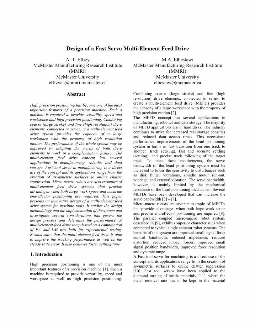
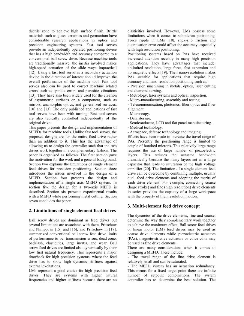
overall system should have consistent dynamics consistency and this requires a research effort to determine how to split the setpoint between the two drive elements. - The dynamic coupling between the two drive elements raises the option of treating the system as either two independent single input single output (SISO) systems, as in [14], or as a multi-input single output (MISO) system. - Geometrical constraints and tolerances of the mechanical components should be designed carefully to keep a determinate resolution and positioning accuracy. Regarding the consistent dynamics problem, two cases may be found depending on the bandwidth of the fine drive element relative to the coarse drive element, and they are: - The fine drive element has much faster dynamics (i.e. much higher bandwidth) than the coarse drive element. - The fine and coarse drive elements have similar dynamics (i.e. no significant difference in bandwidth). In the first case, the setpoint has to be split into two frequency components where the coarse drive element tracks a nominal low frequency trajectory while the fine drive element compensates for the tracking errors and responds to the high frequency component of the trajectory. This design criterion is shown in Figure 1 where the slow dynamics actuator is a LM while the fast dynamics actuator is a PA. This case has applications when the overall bandwidth of the system is required to be increased as well as the precision. In the second case, as shown in Figure 2, the error of the coarse drive element is fed as the setpoint to the fine drive element. This case has applications where the priority is the positioning precision. 4. Multi-element feed drive design for single axis 4.1. Single axis PA flexure base design and analysis A single axis flexure base for the PA was designed to join the two feed drive elements. Figure 3 shows the flexure base assembled with the PA. The flexure base is a frictionless and stick-free parallel-crank linkage that works based on the elastic deformation of a solid material. It eliminates all sliding and rolling actions. It also provides high stiffness and load capacity. When the positioning resolution is on the order of microns flexure bases are superior to conventional bearings. The base material was selected to be Aluminum Alloy
1100-H14 to minimize the total moving mass carried by the LM for better acceleration performance. The material has the following mechanical properties: yield strength 95 MPa and Young’s modulus of elasticity of 70 GPa. The dimensions of the elastic columns in the base were selected to permit the full range of expansion for the PA within the available pushing force of the actuator. This means for an 80 micron expansion a pushing force of 5000 N is required which is 41.6 % of the PA capacity. A finite element (FE) model was built for the flexure base. The model was used to make the static and dynamic analysis for the base. Figure 4 shows the stress distribution of the base due to a 5000 N static force. The maximum stress calculated to be 65 MPa which represents a 1.5 factor of safety. A modal analysis was performed for the base to calculate the natural frequencies and mode shapes. The frequency range under study is 0 – 1000 Hz. This frequency range represents the expected maximum range of excitation force from a milling process. It is equivalent to a slotting operation with a spindle speed of 15,000 rpm and a 4 tooth end mill. No natural frequency occurred in this range; and the first natural frequency for the flexure base with the PA installed was 5000 Hz which is far beyond the excitation frequency. The PA was assembled to the flexure base using two M8 bolts and the assembly is rigidly fixed to the LM moving carriage using four M5 bolts and a 7.8 mm dowel pin. Figure 5 and Figure 6 show the single axis MEFD assembly. The axis is theoretically capable of a 1 m stroke with 20 nm resolution. 4.2. Experimental results and analysis for the single axis The MEFD system is tested against a single element LM drive controlled by a model-based controller and a PID controller to verify the effectiveness and the improved tracking characteristics. Sine wave and ramp inputs are used to compare the tracking error for the three systems, in Figure 6 and 7, while step inputs are used to compare the steady state error between the multi-element and single-element systems, in Figure 8. The maximum tracking and steady state errors are summarized in Table 1. These results show that the multi-element drive is able to improve the tracking performance by about 90% and the steady state error by 50%. It also achieved 3 times faster settling time for the step input (i.e. from 0.045 ms for the single-element drive to 0.015 ms for the MEFD).

Table 1. Comparison in tracking performance between single element drive; LM, and multi-
element drive; LM and PA. Test Type Feed Drive etracking ess
LM (PID Controller) ± 100 µm N/A
LM (Model-Based-Control) ± 30 µm N/A
sine wave 5000 µm,
5.0 Hz vmax =
0.16 m/s Multi-element ± 10 µm N/A LM (PID
Controller) + 80 µm + 80 µm
LM (Model-Based-Control) + 50 µm + 50
µm
Ramp v = 0.2
m/s Multi-element ± 10 µm ± 10
µm
LM N/A -1↔ +4 µm Step
5000 µm Multi-element N/A ± 1
µm ess: steady state error etracking: tracking error 5. Design of two-axis multi-element feed drive This section presents for the design of a two-axis MEFD. The design employs two PAs and two LMs to produce the endpoint movements in two orthogonal directions. 5.1. Two-axis PA flexure base design and analysis A two-axis flexure base is required for the implementation of two identical PAs as the fine actuators. It was designed based on the same concept as the single axis flexure base and it has the same material properties. Figure 9 (a) shows an isometric view for the base assembled with the two PAs. The workpiece fixturing area (WFA) has dimensions of 150 mm × 150 mm. The base was analyzed statically using FE analysis to check on the maximum stress value and the uniformity in displacements of the WFA in the X and Y directions. Figure 9 (b) demonstrates the stress distribution and deflections due to a fixed PA displacement of 80 microns. The stresses reached a maximum of 26 MPa which is 27 % of the material yield strength. No coupling between the two axes or rotating of the WFA was observed. The X and Y displacements were uniform over the WFA. A dynamic FE analysis was required to get an estimate of the natural frequencies and the mode shapes of the flexure base within the range of the
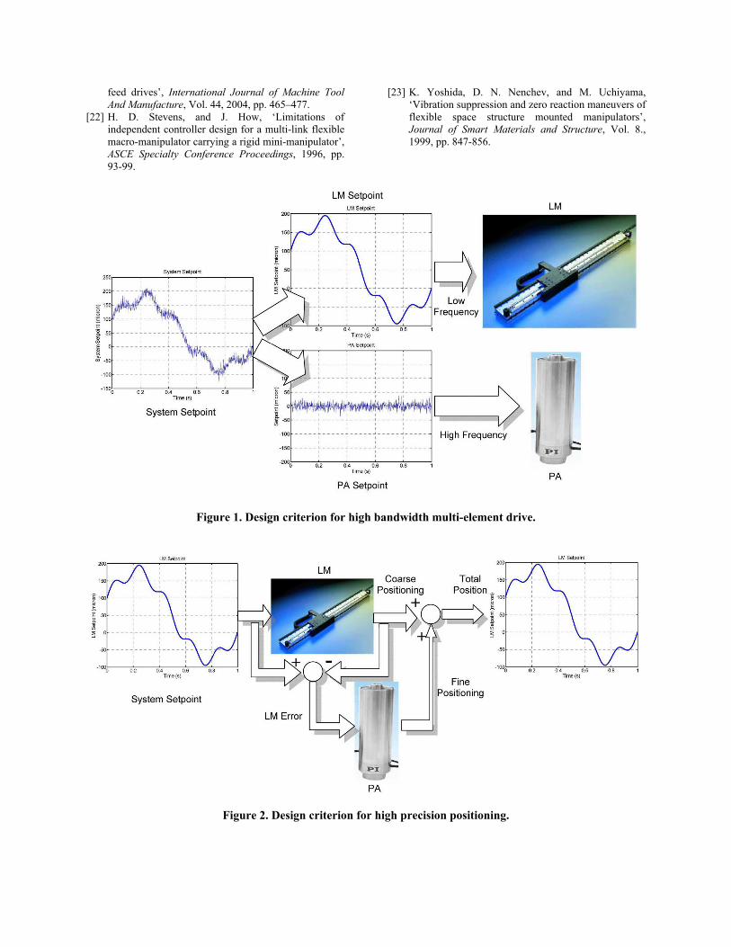
operating frequency. Figure 9 (c) and (d) illustrate the first two mode shapes in the range of 0 – 1000 Hz. The first natural frequency is about 650 Hz while the second natural frequency is about 680 Hz. These two mode shapes are located away from the PA controller bandwidth but can be excited by a cutting process. The spindle speed and the number of teeth of the milling cutter must be selected to avoid these frequencies. 5.2. Design features of the two-axis MEFD Figure 10 illustrates the design of the two-axis MEFD. Two LMs are connected orthogonally in series to form the two-axis coarse drive. The two-axis PA drive is mounted on top of the X axis LM. The design features a base plate to be mounted on an existing machine tool for testing purposes. The design also features high accuracy linear guides and linear bearings. The final resolution and the maximum speed are limited by the LM encoder specifications which are 1 micron resolution and 1 m/s maximum speed in both X and Y directions. 6. Experimental testing in metal cutting Since only one linear motor was available the two-axis MEFD design was not built. Instead a two axes PA flexure base was manufactured and assembled to a single axis LM. The objective was to test the MEFD under real metal cutting conditions. The results of this testing will help to evaluate the performance of the MEFD compared to a single element feed drive. Figure 11 shows the assembly of the two-axis PA flexure base to a LM. This MEFD was installed on a CNC three-axis milling machine. The MEFD was setup to feed the workpiece in the X direction while the CNC machine feeds the whole assembly in the Y direction. The Y axis PA was set to dwell. Two groups of tests were performed, the objective of the first group was to mill a sharp corner and the objective of the second was to mill a sinusoidal profile. The cutting conditions were as follows: cutter diameter = 5 mm (four tooth high speed steel end mill), spindle speed = 12’800 rpm, feed in Y direction = 300 mm/min and depth of cut = 1 mm. For each group a comparison between the LM acting as a single element feed drive and the MEFD were established by monitoring the tracking error. Figure 12 shows a sinusoidal profile cut using the MEFD. Figure 13 presents the experimental tracking performance of both the single element and multi-element drives with sharp corner tracking. Only the data in the vicinity of the corner is plotted. The

results demonstrate that the multi-element drive is able to reduce the maximum tracking error by 38 %. The oscillations in the tracking error were caused by the disturbance force due to the cutting process. The lower frequency component corresponds to the cutter runout frequency while the higher frequency component corresponds to the tooth passing frequency. Figure 14 shows the tracking performance with the sinusoidal profile and demonstrates an 83 % reduction in the maximum tracking error using the MEFD. 7. Conclusions This paper discussed the design of MEFDs for precision machining. In the paper we presented the limitations of single-element feed drives and how MEFDs can improve the performance. The paper also showed some other applications of MEFDs. The paper presented the design issues of a MEFD. One-axis and two-axis MEFDs were designed. A one-axis MEFD was manufactured and implemented. It was used in metal cutting experiments to verify the effectiveness of MEFDs over single-element feed drives. The experiments showed improvements in both transient response and tracking performance. MEFDs have proven effectiveness as suitable feed drives for precision machines. 8. References [1] H. J. Pahk, D. S. Lee, and J. H. Park, ‘Ultra precision
positioning system for servo motor–piezo actuator using the dual servo loop and digital filter implementation’, International Journal of Machine tools and Manufacture, Vol. 41, 2001, pp. 51-63.
[2] S. Kwon, W. K. Chung, and Y. Youm, ‘On the course/fine dual-stage manipulator with robust perturbation compensator’, Proceedings of the 2001 IEEE International Conference on Robotics and Automation, Seoul, Korea, May 21-26, 2001.
[3] H. Numasato, and M. Tomizuka, ‘Settling Control and Performance of a Dual-Actuator System for Hard Disk Drives’, Transactions on Mechatronics, Vol. 8, No. 4, December, 2003, pp. 43.
[4] T. Semba, T. Hirano, J. Hong, and L. Fan, ‘Dual-stage servo controller for HDD using MEMS microactuator’, IEEE Transactions on Magnetics, Vol. 35, No. 5, September, 1999.
[5] G. Guo, D. Wu, and T. C. Chong, ‘Modified Dual-Stage Controller for Dealing with Secondary-Stage Actuator Saturation’, IEEE Transactions on Magnetics, Vol. 39, No. 6, November, 2003.
[6] S. Nakamura, H. Numasato, K. Sato, M. Kobayashi, and I. Naniwa, ‘A push–pull multi-layered piggyback
PZT actuator’, Microsystem Technologies, Vol. 8, 2002, pp. 149–154.
[7] Y. Li, and R. Horowitz, ‘Mechatronics of Electrostatic Microactuators for Computer Disk Drive Dual-Stage Servo Systems’, IEEE/ASME Transactions on Mechatronics, Vol. 6, No. 2, June, 2001.
[8] Z. Jiang, and A.A. Goldenberg, ‘Task space trajectory control of flexible micro/macro robot in the presence of parametric uncertainty’, Mechanism and Machine Theory, Vol. 34, 1999, pp. 1281-1302.
[9] J. B.Morrell, and J.K. Salisbury, ‘Parallel-coupled micro-macro actuators’, International Journal of Robotics Research, Vol. 17, No. 7, July, 1998, pp. 773-791.
[10] Elfizy, A.T., G. Bone, and M. A. Elbestawi, ‘On the use of local linear models for the control of nonlinear piezoelectric actuators’, The 14th International Conference on Flexible Automation and Intelligent Manufacturing, Toronto, Canada, July 12-14, 2004.
[11] S. Ku, G. Larsen, and S. Cetinkunt, ‘Fast tool servo control for ultra-precision machining at extremely low feed rates ‘, Mechatronics, Vol. 8, 1998, pp. 381-393.
[12] M. Crudele, and T. R. Kurfess, ‘Implementation of a fast tool servo with repetitive control for diamond turning’, Mechatronics, Vol. 13, 2003, pp. 243–257.
[13] J. F. Cuttino, C. Miller, Jr., and D. E. Schinstock, ‘Performance Optimization of a Fast Tool Servo for Single-Point Diamond Turning Machines’, IEEE/ASME Transactions on Mechatronics, Vol. 4, No. 2, June 1999.
[14] B. Kim, J. Li, and T. Tsao, ‘Control of a dual stage actuator system for noncircular cam turning process’, Proceedings of the American Control Conference, Arlington, VA, June 25-27, 2001.
[15] G. Pritschow, and W. Philipp, ‘Direct drives for high-dynamic machine tool axes’, Annals of the CIRP, Vol. 39/1/1990, pp. 413-416.
[16] G. Pritschow, and W. Philipp, ‘Research on the efficiency of feed forward controllers in M-direct drives’, Annals of the CIRP, Vol. 41/1/1992, pp. 411-415.
[17] G. Pritschow, ‘A comparison of linear and conventional electromechanical drives’, Annals of the CIRP, Vol. 47/2/1998, pp. 541-548.
[18] P. Van Den Braembussche, J. Swevers, H. VanBrussel, and P. Vanherck, ‘Accurate tracking control of linear synchronous motor machine tool axes’, Mechatronics, Vol. 6, No. 5, 1996, pp. 507-521.
[19] J. Ni, and Z. Zhu, ‘Design of a linear piezomotor with ultra-high stiffness and nanoprecision’, IEEE/ASME Transaction on Mechatronics, Vol. 5, No. 4, December, 2000.
[20] D. K. Lindner, M. Zhu, N. Vujic, and D. J. Leo, ‘Comparison of linear and switching drive amplifiers for piezoelectric actuators’, Collection of Technical Papers - AIAA/ASME/ASCE/AHS/ASC Structures, Structural Dynamics and Materials Conference, Vol. 2, 2002, pp. 1148-1152.
[21] A. T. Elfizy, G. M. Bone, and M. A. Elbestawi, ‘Model based control design for machine tool direct
feed drives’, International Journal of Machine Tool And Manufacture, Vol. 44, 2004, pp. 465–477.
[22] H. D. Stevens, and J. How, ‘Limitations of independent controller design for a multi-link flexible macro-manipulator carrying a rigid mini-manipulator’, ASCE Specialty Conference Proceedings, 1996, pp. 93-99.
[23] K. Yoshida, D. N. Nenchev, and M. Uchiyama, ‘Vibration suppression and zero reaction maneuvers of flexible space structure mounted manipulators’, Journal of Smart Materials and Structure, Vol. 8., 1999, pp. 847-856.
Figure 1. Design criterion for high bandwidth multi-element drive.
Figure 2. Design criterion for high precision positioning.

Figure 3. PA single axis flexure base.
Figure 4. Stress distribution at maximum static deflection.
Figure 5. Single axis MEFD assembly.
Figure 6. Sine wave response and positioning error.
Figure 7. Ramp response and positioning error.

Figure 8. 5000 micron step response and positioning error.
Figure 9. PA two dimensional flexure base design features.

Figure 10. MEFD conceptual design in two dimensions.
Figure 11. Two dimensional flexure base with the PA’s installed.
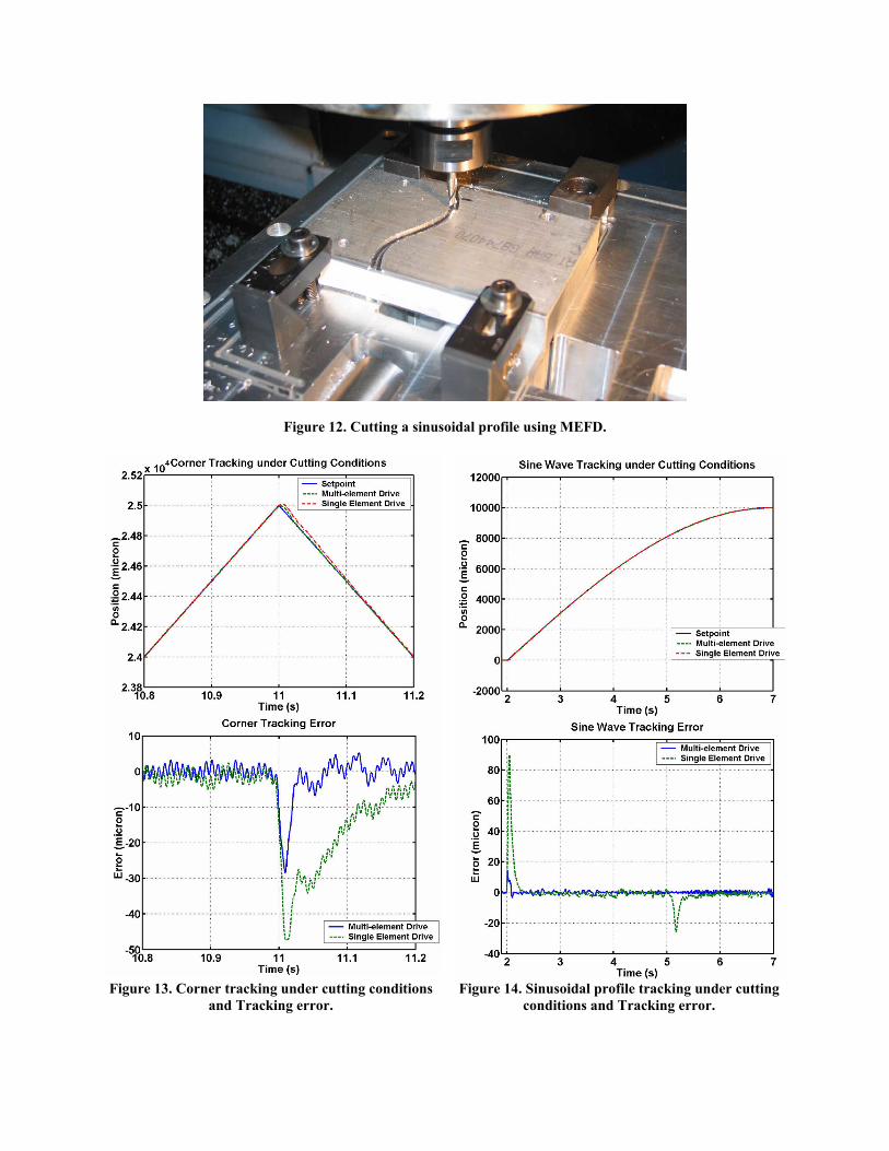
Figure 12. Cutting a sinusoidal profile using MEFD.
Figure 13. Corner tracking under cutting conditions
and Tracking error. Figure 14. Sinusoidal profile tracking under cutting
conditions and Tracking error.

![3.3 LINEAR FEED ASSEMBLAGES · Fig. 3.3.2: Type execution example of the linear feed assemblage [Toshulin] through the ball screw. The rotary AC servo drive is connected to the ball](https://static.fdocuments.in/doc/165x107/5fb92888a3d1521376095257/33-linear-feed-fig-332-type-execution-example-of-the-linear-feed-assemblage.jpg)