MAGNUM SERVO FEED
20
Installation and Operating Instructions MAGNUM SERVO FEED MODELS SRF-M12 / 18 / 24 / 32 / 36 / 48 P/A INDUSTRIES INC. 522 Cottage Grove Road • Bloomfield, Connecticut 06002-3191 U.S.A. Toll Free 1-800-243-8306 • Worldwide 1-860-243-8306 • Fax 1-860-242-4870 Website http://www.pa.com • E-Mail [email protected] ®
Transcript of MAGNUM SERVO FEED
Installation and Operating Instructions
MAGNUM SERVO FEEDMODELS SRF-M12 / 18 / 24 / 32 / 36 / 48
P/A INDUSTRIES INC.522 Cottage Grove Road • Bloomfield, Connecticut 06002-3191 U.S.A.Toll Free 1-800-243-8306 • Worldwide 1-860-243-8306 • Fax 1-860-242-4870Website http://www.pa.com • E-Mail [email protected]
®

1. INTRODUCTION .................................... 2
2. HOW A MAGNUMSERVO FEED OPERATES .................... 2
3. INSTALLING YOUR MAGNUMSERVO FEED ........................................ 3
3.1 MECHANICAL INSTALLATION ......... 33.2 ELECTRICAL INSTALLATION .......... 33.3 ELECTRICAL CONNECTIONS ........ 33.4 MAGNUM MOUNTING HOLES ........ 4
4. PROGRAMMING THE MAGNUM SERVO FEED SYSTEM ........................ 4
4.1 PROGRAM A NEW FEEDLENGTH, COUNT, SPEED ............... 5
4.2 PROGRAM A NEW BATCHCOUNT ............................................. 6
4.3 PROGRAM A NEW SPEEDFOR THE FEED ................................ 6
5. OPERATING THE FEED ....................... 65.1 PRIORITY MODE .............................. 75.2 SET-UP MODE .................................. 75.3 AUTO/MANUAL MODE ..................... 75.4 LOADING THE FEED ........................ 75.5 RUNNING THE FEED ....................... 9
6. TROUBLESHOOTING GUIDE ..............116.1 PRO-200 MOTION
CONTROL CARD ERRORS ............126.2 DDM DRIVE ERROR MESSAGES ..136.3 RUN TIME ERROR CODES ............136.4 POWER-UP ERROR CODES ..........13
7. MAINTENANCE ....................................13
8. MAGNUM MECHANICALPARTS LIST AND DIAGRAM................14
9. CASCADE WITHOUT ENCODERPARTS LIST AND DIAGRAM................17
10. CASCADE WITH ENCODERPARTS LIST AND DIAGRAM .............. 18
WARNING .....................................................20
SAFETY PROGRAM ....................................20
WARRANTY .................................................20
1. INTRODUCTIONThe P/A Industries Magnum Heavy Duty ServoRoll Feed combines the latest servo roll feed designtechnology with the latest servo drive controltechnology. Years of testing and experience has led tomany of the design features found in the Magnum.
A high strength cast iron frame forms the core ofthe Magnum. Large diameter textured feed rollswith driven upper and lower rolls assure positivefeeding of the strip without slipping. A precisionworm-gear reducer provides the torquemultiplication necessary for optimum pullingcapacity required on heavier material.
A brand new high performance digital servo drive isthe heart of the Magnum. The new drive incorporatesall the latest motor control, tuning, and protectionfeatures available. Standard features of the Magnumcontroller include: Jog-To-Feed Length; Press OrFeed Priority Selection, Press/Feeder SynchronousChecking; Hand Held Jog Pendant with RollRelease Selector; and many more.
The mechanical simplicity, accuracy, and ease of useof your new Magnum Heavy Duty Servo RollFeeder should help you improve your quality andproduction for years to come.
2. HOW A MAGNUM SERVO FEED OPERATES
The Magnum Servo Roll Feed consists of:
2.1 THE MECHANICAL COMPONENTS(Refer to Figure 1)
1) Feeder Housing & Feed Rolls2) Worm-Gear Speed Reducer3) Servo Motor4) Air Actuated Roll Release5) Cascade Guide Rolls6) OPTIONAL-Cascade Guide Rolls
With Strip Encoder
2.2 THE ELECTRICAL CONTROLENCLOSURE ASSEMBLY(Refer to Figure 1)
7) Operators Control Panel & Data Entry Terminal8) 24 VDC Logic Power Supply (For Controls) 9) Cabling
2
DRAWING 17573-01
DESCRIPTION PAGE
TABLE OF CONTENTS
Figure 1.
RECEIVING INSPECTIONBefore removing unit from its packaging, check forvisual damage, especially if crate, skid, or carton has
been damaged in transit. Any damage caused byshipping should be immediately reported to thecarrier. If unit appears in satisfactory condition,remove all packing and wipe rust preventive from
rollers with mild solvent.

When a new feed pitch is entered into the system,the built in computer calculates the correct numberof electronic “pulses” it must receive from the motormounted encoder in order to rotate the feed rollsthe correct amount. This will accurately positionthe strip.
Fifteen and one-half revolutions of the servo motorshaft produce 1 revolution of the feed rollers. Themotor-mounted optical encoder produces 8000"pulses" for each revolution of the motor. The circumference of the lower roll is 14.842 inches.
Example: If a feed pitch/length of 14.842 inches isentered into the feeder, this will result in exactlyone revolution of the feed rolls. The motor willaccelerate and turn 15.5 turns. This will produce(15.5 x 8000) =124,000 pulses of the encoder.The feeder will decelerate and stop when 124,000pulses are detected. The feeder is now on position.This entire process happens very quickly, the endresult is an accurately positioned strip exactly14.842 inches from its starting point. This entireprocess happens in milliseconds.
3. INSTALLING YOURMAGNUM SERVO FEED
3.1 MECHANICAL INSTALLATIONThe Magnum Servo Roll Feed is supplied witha height adjustable mounting bracket for the feeder.The adjustment is (± 2.0 inch) from middleposition. The feeder should be securely mounted tothe press frame. A transition bracket is sometimesrequired in certain applications requiring moreadjustment.
The feeder should be centered, square, andperpendicular to the pass line of the press. Use the24 millimeter square keys on the front mountingplate for alignment and leveling the feeder. Thefeeder should be mounted at a height that willaccommodate the appropriate die sets. Refer toFigure 2 on Page 4.
The feeder can be used to push or pull stock.
3.2 ELECTRICAL INSTALLATIONThe Magnum Servo Roll Feed has been designedto make electrical connections quickly and easily.A clean 220 VAC single phase 20 ampere source isrequired for trouble free operation. The inputs andoutputs to your press control (i.e. Emergency stop,Feed advance cam contact, Continue cam contact,Pilot Release Cam Contact (if used), and Tautor No Loop Input) must be connected accordingto the electrical schematic instructions includedwith machine. The motor connects by a factoryinstalled "Amphenol" (Military Specifications)
3
NOTE:All connections should be made in accordance with National Electrical Code (NEC)requirements and must comply with all local ordinances.
IMPORTANT! A #12 MTW grounding conductor must be installed for proper machine grounding.
NOTE:A word about electrical “noise”. Most pressroom environments contain considerable electrical noise.It is emitted from electro-mechanical press relays,contacts, and solenoids. While The Magnum Servo Roll Feed has been designed to minimize "self generated" electrical noise, it is difficult to provide protection for all applications. If erratic system behavior is experienced, then the source of the "noise" must be suppressed with either a resistive/capacitive type of suppressor on AC coils, or “Avalanche” type diodes on DC coils.
NOTE:The Magnum Servo Roll Feed is fully protected by a disconnect switch and line fuses. If it becomes necessary to replace the fuses, use only exact equivalent fuse types to prevent serious damage to the system.
Quick connectors. The electrical Control Enclosureis supplied with a stand/support which may beplaced in any convenient location. The enclosuremay also be mounted in any fixed location as longas cabling is adequate to reach the feeder. It is notrecommended that the Electrical Enclosure bemounted directly to the press. The vibrationscaused by the press may result in damage to thecontrol system.
3.3 ELECTRICAL CONNECTIONSFor more detailed wiring information, refer to Electrical Schematic A-17514-01 for 220 VACor 440 VAC
The main power for the feed system requires a“clean” 220 VAC single phase 20 ampere source.A terminal strip is provided in the main controlenclosure to facilitate wiring connections. It isrecommended that #12 MTW (Machine Tool Wire)be used for the primary power supply input.

3.4 MAGNUM MOUNTING HOLES STEP #1:Turn on the main power disconnect switch. Thisapplies power to the control power supply. Press theamber ‘POWER ON’ push-button. The button willilluminate and the data input display will be visible:
☞
STEP #2:Press any key on the terminal, the displaywill show:
☞
STEP #3:The ‘POWER ON’ push-button has a ‘FAULTRESET’ function built into the button. Press the‘POWER ON’ button to clear the ‘ENCODERFAULT’ message at the bottom line of the display.The feed may now be jogged forward by pressingthe ‘JOG FORWARD’ button, or jogged in reverseby pressing the ‘JOG REVERSE’ button.
The Magnum Servo Roll Feed has six viewablescreens. Only the first operator screen (shownabove) will be operator editable/programmable.This screen displays the length, count, and speedparameters. These parameters may only be changedwhile the program is stopped (indicated by lack of‘CYCLE START’ or set up light). The otherviewable screens are shown on the following page.
These five other screens will be viewable at all times,but are “locked” out of programming via run/progswitch located on the electrical panel inside theelectrical enclosure. The factory set parametervalues for the Magnum Servo Roll Feed are printedon the operator panel below the operator terminal.These parameters are set from the factory foraverage feeding applications and they seldomrequire any changes. The five screens and a briefexplanation of the parameters are described below:
• LENGTH: Distance in inches (or millimeters) of the feed length. Maximum value of 999.750 inches.
• COUNT: The number of pieces required to run in the batch. Maximum value of 999,999 pieces.
MODEL A B C D
SRF-M12 310 620 670 467
SRF-M18 387 775 825 619
SRF-M24 462 925 975 772
SRF-M32 565 1130 1181 972
SRF-M36 615 1230 1280 1076
SRF-M48 765 1529 1580 1377
4
P/A INDUSTRIESSERVO ROLL FEED
VERSION 1.00HIT KEY TO CONT__
LENGTH 00008.000COUNT 100000SPEED 0060/SEC
ENCODER FAULT
C
D
4.3” (109mm)
3.1” (80mm)
5.9”(150mm)
B
A
DRAWING 17573-02
PASS LINEHEIGHT
ADJUSTMENT± 2.0”
ø0.67” (ø17mm)(4) MOUNTINGHOLES
PASS LINE
MILLIMETERS
MODEL A B C D
SRF-M12 12.2 24.4 26.4 18.4
SRF-M18 15.3 30.5 32.5 24.4
SRF-M24 18.2 36.4 38.4 30.4
SRF-M32 22.3 44.5 46.5 38.3
SRF-M36 24.2 48.4 50.4 42.4
SRF-M48 30.1 60.2 62.2 54.2
INCHES
MAGNUM MOUNTING HOLES for drawing 17573-02
Figure 2.
4. PROGRAMMING THE MAGNUMSERVO FEED SYSTEM
IMPORTANT !Before turning the system on for the first time, verify that the main input voltage is correct (220vac single phase) and inspect all connections for tightness, shorts, etc.

• SPEED: The maximum velocity of the material in inches/second (or millimeter/second). Maximum value of 60 inches/second.
☞
• ACCEL: The rate of acceleration ininches/second2 (or millimeter/second2). Maximum value of 1000 inches/second2.
• DWELL: The time delay which controls the ‘ON’ duration of the cut output relay. The dwell is usedwhen the press or shear, lacks a continue Bottom Dead Center (BDC) switch and the cycle can be controlled by the dwell parameter.
• DBNC: This is the debounce parameter, whichis used to ignore contact bounce on the feed signals.
☞ • PRIORITY: This parameter selects whether the
feeder indexes before the press starts ‘FBP’ (Feed-Before-Press), or the press starts before the feeder indexes ‘PBF’ (Press-Before-Feed). Entering a ‘0’ selects ‘PBF’ mode or a ‘1’ selects ‘FBP’ mode.
• BACKLIGHT: This turns on the backlight in the display, which enhances the viewing.
☞• CNTS/UNIT: This is the encoder scaling
parameter used to define the number encoder counts/inch (or counts/millimeter).
• TIME BASE: Time scaling parameter for various parameters. This is always set to ‘/SEC’ by entering ‘0’.
• JOG SPEED: The rate of jogging speed inpercent of the SPEED parameter. Normally set between 1 - 5%.
• DIRECTION: This parameter controls thedirection of positive motor rotation. 0 = CCW, and 1 = CW.
☞
• KP: Proportional gain parameter for the motion control. It controls the transitions between the starting and stopping of the rolls. A lower value provides a smoother (slower) transition.
• KD: This parameter is not used.
• KFF: Velocity feed forward gain. This is used to reduce following error of the system.
• AUTO OFFSET: This parameter turns theautomatic offset on. Turn this feature on by entering ‘1’.
☞
• INPOSN: In-position parameter is a tolerance window around the final position. This is used toverify the feed index accuracy is within acceptablelimits before continuing onto the next function.
• FELim: Follower error limit. FELim is themaximum allowed position error. When this limitis exceeded for the amount of time specified by the FETime, the control will execute anemergency stop.
• FETime: Follower error time. FETime is the maximum amount of time that the following errorlimit may be exceeded before executing an emergency stop.
• SYSTEM RESET: This function clears allparameters to the factory default conditions. No program may be running, RESET must be active (press and hold the ‘POWER ON’ button), and the ‘PROG/RUN’ switch must be set to ‘PROG’ position. Pressing ‘1’ while the cursor is on the SYSTEM RESET line will result in a confirmationscreen being displayed. Pressing ‘1’ a second time will reset the parameters to the factory default values and the power-up screen will bedisplayed. Pressing any other key than ‘1’ willresult in aborting the system reset.
4.1 PROGRAM A NEW FEEDLENGTH, COUNT, SPEED
To program a new feed pitch/length the programmust be stopped. This may be done by pressing the‘POWER ON’ or the ‘CYCLE STOP’ button(if the press is running). Press the ‘OPERATOR’button to view the following screen:
5
ACCEL 000402/SEC^2DWELL 00.00DBNC 1 X 3.75MS
PRIORITY PBFBACKLIGHT ON
CNTS/UNIT 8396TIME BASE /SECJOG SPEED 5%DIRECTION CCW
KP 0.30KD 0.00KFF 0.30AUTO OFFSET ON
INPOSN 000.0200FELIM 5.000FETIM 0.500SYSTEM RESET
☞
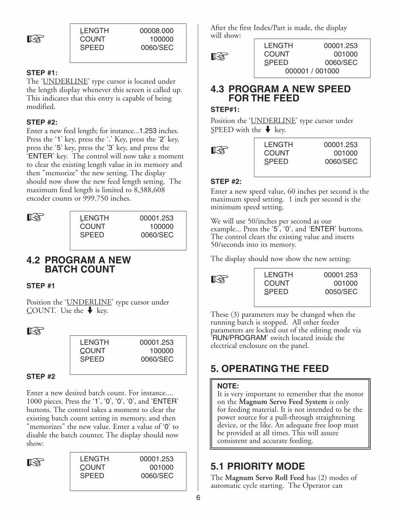
STEP #1:The ‘UNDERLINE’ type cursor is located underthe length display whenever this screen is called up.This indicates that this entry is capable of beingmodified.
STEP #2:Enter a new feed length; for instance...1.253 inches.Press the ‘1’ key, press the ‘.’ Key, press the ‘2’ key,press the ‘5’ key, press the ‘3’ key, and press the‘ENTER’ key. The control will now take a momentto clear the existing length value in its memory andthen "memorize" the new setting. The displayshould now show the new feed length setting. Themaximum feed length is limited to 8,388,608encoder counts or 999.750 inches.
☞
4.2 PROGRAM A NEWBATCH COUNT
STEP #1
Position the ‘UNDERLINE’ type cursor underCOUNT. Use the◗ key.
☞
STEP #2
Enter a new desired batch count. For instance....1000 pieces. Press the ‘1’, ‘0’, ‘0’, ‘0’, and ‘ENTER’buttons. The control takes a moment to clear theexisting batch count setting in memory, and then"memorizes" the new value. Enter a value of ‘0’ todisable the batch counter. The display should nowshow:
☞
6
After the first Index/Part is made, the displaywill show:
☞
4.3 PROGRAM A NEW SPEED FOR THE FEED
STEP#1:
Position the ‘UNDERLINE’ type cursor underSPEED with the◗ key.
☞
STEP #2:Enter a new speed value, 60 inches per second is themaximum speed setting. 1 inch per second is theminimum speed setting.
We will use 50/inches per second as ourexample... Press the ‘5’, ‘0’, and ‘ENTER’ buttons.The control clears the existing value and inserts50/seconds into its memory.
The display should now show the new setting:
☞
These (3) parameters may be changed when therunning batch is stopped. All other feederparameters are locked out of the editing mode via‘RUN/PROGRAM’ switch located inside theelectrical enclosure on the panel.
LENGTH 00008.000COUNT 100000SPEED 0060/SEC
LENGTH 00001.253COUNT 100000SPEED 0060/SEC
LENGTH 00001.253COUNT 100000SPEED 0060/SEC
LENGTH 00001.253COUNT 001000SPEED 0060/SEC
LENGTH 00001.253COUNT 001000SPEED 0060/SEC
LENGTH 00001.253COUNT 001000SPEED 0060/SEC
000001 / 001000
LENGTH 00001.253COUNT 001000SPEED 0050/SEC
5. OPERATING THE FEED
NOTE:It is very important to remember that the motor on the Magnum Servo Feed System is only for feeding material. It is not intended to be the power source for a pull-through straightening device, or the like. An adequate free loop must be provided at all times. This will assureconsistent and accurate feeding.
5.1 PRIORITY MODEThe Magnum Servo Roll Feed has (2) modes ofautomatic cycle starting. The Operator can

7
choose between ‘PRESS-BEFORE-FEED’ (PBF)and ‘FEED-BEFORE-PRESS’ (FBP) operating mode.
When ‘PBF’ mode is selected and the ‘CYCLESTART’ button is pressed on the control panel, thefeeder causes the ‘AUTO’ and ‘PERMIT PRESS’relays to turn on thus enabling the start ofcontinuous cycling on the press.
When ‘FBP’ is selected and the ‘CYCLE START’button is pressed on the feed control, the material/strip will be fed forward the programmed pitchbefore the press is started. The Operator may verifythat the strip is in position before starting the press.
The Magnum Servo Roll Feed will now follow thepress until it is stopped by the Operator, counter,emergency stop, or feed error.
5.2 SET-UP MODE‘SET-UP MODE’ is used primarily during the threadingof the strip through the die. This mode allows the‘JOG-TO-FEED’ Length operations to be performed.
While in ‘SET-UP MODE’, the strip may be movedusing the ‘JOG FORWARD’ operator button. Ifthe ‘JOG FORWARD’ is stopped before the ‘FEEDLENGTH’ is reached, then either the ‘JOG FOR-WARD’, or ‘JOG REVERSE’ operator buttons willwork. The ‘JOG REVERSE’ will not allow thestrip to go backwards beyond the initial ‘FEEDLENGTH’ starting point. The ‘JOG FORWARD’operator button will function until the end of the‘FEED LENGTH’ is reached.
During ‘SET-UP MODE’, the bottom line on thedisplay will show ‘WAITING FOR JOG’. When the‘FEED LENGTH’ is reached, the jog buttons becomein active and the message on the display will show‘WAITING FOR PRESS’. The jog buttons will notbecome active again until after the press has made acycle.
5.3 AUTO/MANUAL MODE‘AUTO MODE’ is used for production running ofthe Edge Servo Roll Feed. When ‘AUTO’ is selectedvia the 2-position selector switch, the control is putinto ‘MANUAL MODE’ until the ‘CYCLE START’button is pressed. During manual mode, the feedermay be jogged infinitely in either direction. Afterthe ‘CYCLE START’ button is pushed, the jogbuttons are inactive, and the feeding of the stripfollows the cam signals from the press. During‘AUTO MODE’, the control keeps check onsynchronization of the feeder and press. If theFeeder does not complete the index within the feedcam window, the message ‘SYNC FAULT’ displays.
The Magnum Servo Roll Feed has (2) modes ofautomatic cycling. The feeder can operate with‘SINGLE STROKE’ or ‘CONTINUOUS PRESS
MODE’. The mode is selected through an input to thefeed controller. The press single stroke/continuousmode switch should be interfaced to this input forproper operation. During ‘SINGLE STROKE’mode operation, the ‘PERMIT PRESS’ output relayis activated upon the completion of each feed index.The ‘PERMIT PRESS OUTPUT RELAY’ remainsactive until the continue cam signal turns on. The‘PERMIT PRESS OUTPUT RELAY’ may be usedto signal the press when to initiate the single strokecycle. The automatic cycling of the press and feederwill continue until the batch is completed, or thecycle is stopped by the operator, or an error occurs.
During ‘CONTINUOUS PRESS MODE’, the‘PERMIT PRESS OUTPUT RELAY’ turns on at thebeginning of the indexing. The ‘PERMIT PRESSRELAY’ remains active until the automatic cyclingis stopped by either ‘CYCLE STOP’, ‘BATCHCOMPLETE’, ‘SYNC FAULT’, or any other driverelated error. Under ‘CYCLE STOP’ or ‘BATCHCOMPLETE’ stopping, the output will turn off atthe beginning of the ‘FEED CAM SIGNAL’. Thisshould allow the press to stop near the top of thestroke. Under ‘SYNC FAULT’ or other drive faultconditions, the ‘PERMIT PRESS RELAY’ will turnoff immediately upon detection of the error.
5.4 LOADING THE FEEDThe material thickness and width table below definesthe maximum stock thickness at full width allowed.It also defines the maximum material speed andcycles per minute (CPM). Do not try to operate thefeeder with material thicker than it was deigned tofeed. READ THIS TABLE BEFORE LOADINGANY MATERIAL INTO THE FEEDER.
MILLIMETERS
Max. Max.Stock Cross Max.
Max. Max. Thick. Section Material Max.Stock Stock At Full Area Speed Feed
Model Width Thick. Width Sq. In. Ft./Min. C.P.M.
SRF-M12 12.0 .250 .200 2.4 315 600
SRF-M18 18.0 .250 .187 3.4 315 600
SRF-M24 24.0 .250 .164 4.0 315 600
SRF-M32 32.0 .250 .136 4.3 315 600
SRF-M36 36.0 .250 .125 4.5 315 600
SRF-M48 48.0 .250 .094 4.5 315 600
Max. Max.Stock Cross Max.
Max. Max. Thick. Section Material Max.Stock Stock At Full Area Speed Feed
Model Width Thick. Width Sq. mm M/Min. C.P.M.
SRF-M12 305 6.3 5.1 1550 96 600
SRF-M18 457 6.3 4.7 2200 96 600
SRF-M24 610 6.3 4.2 2600 96 600
SRF-M32 813 6.3 3.4 2800 96 600
SRF-M36 914 6.3 3.2 2900 96 600
SRF-M48 1220 6.3 2.4 2900 96 600
INCHES
8
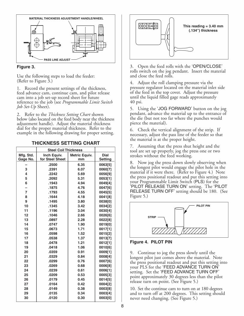
3. Open the feed rolls with the ‘OPEN/CLOSE’rolls switch on the jog pendant. Insert the materialand close the feed rolls.
4. Adjust the roll clamping pressure via thepressure regulator located on the material inlet sideof the feed in the top cover. Adjust the pressureuntil the liquid filled gage reads approximately40 psi.
5. Using the ‘JOG FORWARD’ button on the jogpendant, advance the material up to the entrance ofthe die (but not too far where the punches wouldpierce the material).
6. Check the vertical alignment of the strip. Ifnecessary, adjust the pass line of the feeder so thatthe material is at the proper height.
7. Assuming that the press shut height and thetool are set up properly, jog the press one or twostrokes without the feed working.
8. Now jog the press down slowly observing whenthe longest pilot would engage the pilot hole in thematerial if it were there. (Refer to Figure 4.) Notethe press positional readout and put this setting intoyour Programmable Limit Switch (PLS) for the‘PILOT RELEASE TURN ON’ setting. The ‘PILOTRELEASE TURN OFF’ setting should be 180. (SeeFigure 5.)
9. Continue to jog the press slowly until thelongest pilot just comes above the material. Notethe press positional readout and put this setting intoyour PLS for the ‘FEED ADVANCE TURN ON’setting. Set the ‘FEED ADVANCE TURN OFF’point approximately 30 degrees less than the pilotrelease turn on point. (See Figure 5.)
10. Set the continue cam to turn on at 180 degreesand to turn off at 200 degrees. This setting shouldnever need changing. (See Figure 5.)
STRIP
PILOT PIN
Figure 4. PILOT PIN
0 0 3 4 0 This reading = 3.40 mm(.134”) thickness
PASS LINE ADJUST
MATERIAL THICKNESS ADJUSTMENT HANDLE/WHEEL
Figure 3.
Use the following steps to load the feeder:(Refer to Figure 3.)
1. Record the present settings of the thickness,feed advance cam, continue cam, and pilot releasecam into a job set-up record sheet for futurereference to the job (see Programmable Limit SwitchJob Set-Up Sheet).
2. Refer to the Thickness Setting Chart shownbelow (also located on the feed body near the thicknessadjustment handle). Adjust the material thicknessdial for the proper material thickness. Refer to theexample in the following drawing for proper setting.
Steel Coil ThicknessMfg. Std. Inch Equiv. Metric Equiv. DialGage No. for Steel Sheet mm Setting
– .2500 6.35 0063[5]3 .2391 6.07 0060[7]4 .2242 5.69 0056[9]5 .2092 5.31 0053[1]6 .1943 4.94 0049[4]– .1875 4.76 0047[6]7 .1793 4.55 0045[5]8 .1644 4.18 0041[8]9 .1495 3.80 0038[0]10 .1345 3.42 0034[2]11 .1196 3.04 0030[4]12 .1046 2.66 0026[6]13 .0897 2.28 0022[8]14 .0747 1.90 0019[0]15 .0673 1.71 0017[1]16 .0598 1.52 0015[2]17 .0538 1.37 0013[7]18 .0478 1.21 0012[1]19 .0418 1.06 0010[6]20 .0359 0.91 0009[1]21 .0329 0.84 0008[4]22 .0299 0.76 0007[6]23 .0269 0.68 0006[8]24 .0239 0.61 0006[1]25 .0209 0.53 0005[3]26 .0179 0.45 0014[5]27 .0164 0.42 0004[2]28 .0149 0.38 0003[8]29 .0135 0.34 0003[4]30 .0120 0.30 0003[0]
THICKNESS SETTING CHART
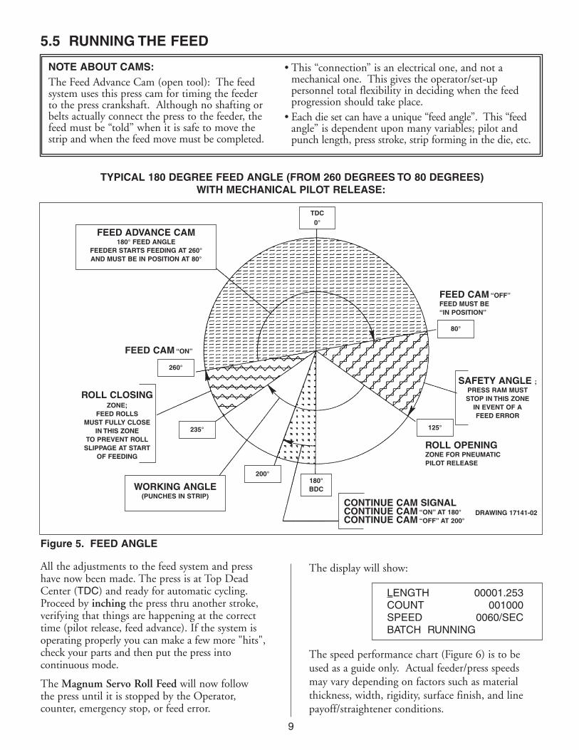
TYPICAL 180 DEGREE FEED ANGLE (FROM 260 DEGREES TO 80 DEGREES)WITH MECHANICAL PILOT RELEASE:
9
FEED ADVANCE CAM180° FEED ANGLE
FEEDER STARTS FEEDING AT 260°AND MUST BE IN POSITION AT 80°
WORKING ANGLE (PUNCHES IN STRIP)
FEED CAM “ON”
FEED CAM “OFF”FEED MUST BE“IN POSITION”
SAFETY ANGLE ;PRESS RAM MUSTSTOP IN THIS ZONE
IN EVENT OF AFEED ERROR
ROLL OPENING ZONE FOR PNEUMATICPILOT RELEASE
DRAWING 17141-02CONTINUE CAM SIGNALCONTINUE CAM “ON” AT 180°CONTINUE CAM “OFF” AT 200°
Figure 5. FEED ANGLE
260°
80°
125°
TDC0°
180°BDC
235°
200°
ROLL CLOSINGZONE;
FEED ROLLSMUST FULLY CLOSE
IN THIS ZONETO PREVENT ROLL
SLIPPAGE AT STARTOF FEEDING
5.5 RUNNING THE FEED
NOTE ABOUT CAMS:The Feed Advance Cam (open tool): The feed system uses this press cam for timing the feederto the press crankshaft. Although no shafting orbelts actually connect the press to the feeder, thefeed must be “told” when it is safe to move thestrip and when the feed move must be completed.
• This “connection” is an electrical one, and not a mechanical one. This gives the operator/set-uppersonnel total flexibility in deciding when the feed progression should take place.
• Each die set can have a unique “feed angle”. This “feedangle” is dependent upon many variables; pilot and punch length, press stroke, strip forming in the die, etc.
All the adjustments to the feed system and presshave now been made. The press is at Top DeadCenter (TDC) and ready for automatic cycling.Proceed by inching the press thru another stroke,verifying that things are happening at the correcttime (pilot release, feed advance). If the system isoperating properly you can make a few more "hits",check your parts and then put the press intocontinuous mode.
The Magnum Servo Roll Feed will now followthe press until it is stopped by the Operator,counter, emergency stop, or feed error.
The display will show:
The speed performance chart (Figure 6) is to beused as a guide only. Actual feeder/press speedsmay vary depending on factors such as materialthickness, width, rigidity, surface finish, and linepayoff/straightener conditions.
LENGTH 00001.253COUNT 001000SPEED 0060/SECBATCH RUNNING

10
Figure 6. SPEED PERFORMANCE CHART
NOTES ABOUT"POSSIBLE PROBLEM TOOLING":* • A tight die, one that is not square, or has other
tooling problems, will cause significant difficulty and downtime. Accuracy in feeding is directly related to how easily the feeder can position the strip in the die. Binding, bad part ejection, or sticking parts may cause the material to "jam" inthe die.
• The Magnum Servo Roll Feed will "try" toovercome the "jam-up" by applying more power to the rolls.
ONE OF FOUR OUTCOMES WILL RESULT:• The feed will continue to try to move the strip
(if the rolls do not slip) until the feed advance cam opens. A Sync Fault Error will occur and the press will be stopped by the feeder.
• The feed will apply more power to the rolls, causing them to slip on the material. Thisproduces a "short-feed". In reality the feeder
did not "misfeed". The rolls were positionedproperly, the strip did not keep up, causing the die to close and a miss-hit is produced.
• The feed applies more power to a thin strip, causing the material to buckle somewhere between the feed and the die set. The feeder positioned the strip accurately, it just did not occur in the die set.
• The feed tries to apply so much power to a heavystrip in order to move it, that excessive current is drawn by the servo drive. This results in the drive shutting down to protect itself and in doingso stops the press.
NOTE: The feed detected a problem and emergency-stopped the press before the die closed. In using the Magnum Servo Roll Feed, you in fact have added a "die protection" system to your tooling.
* A tooling problem is a problem caused by tooling and not the Feeder itself.
VELOCITY = 60 In./Sec. ACCEL = 402 In./Sec2 FEED CAM WINDOW DEGREESSTROKES PER MINUTE
FEED (In.) FEED (mm) FEED TIME (Sec.) 90° 180° 270°0.25 6.35 0.075 200 400 6000.50 12.7 0.096 157 313 4700.75 19.05 0.112 134 269 4031.00 25.4 0.125 120 240 3602.00 50.8 0.166 90 180 2703.00 76.2 0.198 76 151 2274.00 101.6 0.225 67 133 2005.00 127 0.249 60 121 1816.00 152.4 0.270 56 111 1677.00 177.8 0.290 52 104 1558.00 203.2 0.308 49 97 1469.00 228.6 0.325 46 92 138
10.00 254 0.341 44 88 13211.00 279.4 0.357 42 84 12612.00 304.8 0.371 40 81 12114.00 355.6 0.399 38 75 11316.00 406.4 0.425 35 71 10618.00 457.2 0.449 33 67 10020.00 508 0.472 32 64 9522.00 558.8 0.494 30 61 9124.00 609.6 0.515 29 58 8726.00 660.4 0.535 28 56 8428.00 711.2 0.555 27 54 8130.00 762 0.575 26 52 7835.00 889 0.625 24 48 7240.00 1016 0.675 22 44 6745.00 1143 0.725 20 41 6250.00 1270 0.775 19 39 5855.00 1397 0.825 18 36 5560.00 1524 0.875 17 34 51

11
SYMPTOM CAUSE or REMEDY
No power indication when • Check main power supply for proper voltage.‘POWER ON’ button is pressed • Check supply fuses and circuit breakers.
• Verify that the main disconnect switch is on.
• Verify that the E-Stop is not engaged (E-Stop Loop closed.)
• Check bulb in ‘POWER ON’ push button.
No display on power up • Check cabling connection between display and servo drive.• Check 5 Volt logic supply LED on motion control card on right side
of Servo Drive/Amplifier under orange connectors.• Check fuses in drive under right side cover.
Feed will not jog • Check that the Feed is in manual mode. Move selector switch to ‘AUTO’;press the ‘POWER ON’ push button to reset control.
• Check if the Feed is in ‘SET-UP’ mode. Waiting for press.• Check if ‘IN POSITION’ indicator is off. Check parameters. Check drive
for Error Codes.• Check ‘FAULT’ in display. i.e. ‘SERVO AMP FAULT’. Check drive for Error
Code. See Section 6.1
‘POWER ON’ indicator is lit, • Check that the ‘IN POSITION’ indicator is lit. If not, check parameters.Feed will not operate. • Check that the Error message is in the Display. If so, check error
description in Section 6.1 • Move selector switch to Auto, press ‘POWER ON’ button (E-Stop will show
in display), release ‘POWER ON’ button, try to jog feeder.
Feed will not accept new feed • Check that the Selector switch is in Set-Up mode (running Set-Up program).length or other parameters • Check that the Selector switch is in Auto mode and ‘CYCLE START’ has
been pressed (running Auto Program). Press ‘POWER ON’ push buttonto reset.
• Check that the Run/Program toggle switch is in ‘RUN’ position; this will onlyallow length, speed, and count to be changed. Set the Program Position;then the Program position will allow any parameter to be changed.
Inaccurate feeding • Adjust rolls for correct material thickness. Check thickness gauge.• Adjust air pressure.• Confirm if rolls are slipping on strip. Remove oil from feed rolls, reduce
acceleration, check tool for binding/slugs, etc.• Adjust Upstream Equipment if Upstream equipment not providing
adequate/consistent free loop.• Check roll release for proper settings.
Feed runs backwards • Check for negative feed length, i.e. minus sign in length (–5.125).• Verify that direction parameter has been reset. Check CW or CCW
direction parameter.
Servo Amp Fault This is a generic display prompt indicating a fault on the Servo Amplifier.• Look at the diagnostic display on the Servo Amplifier. The cause of the
fault can be determined by reading the Error Code.• Refer to Sections 6.1 and 6.2. This fault condition can be caused by any
one of the errors in the lists.• Check for Error Code first, then reset the Servo Amplifier by turning the
power off, waiting 10 seconds, then powering back on.• Verify that the fault will not reset. Call the factory for assistance.
6. TROUBLESHOOTING GUIDEThe chart that follows contains the most frequently encountered issues.
12
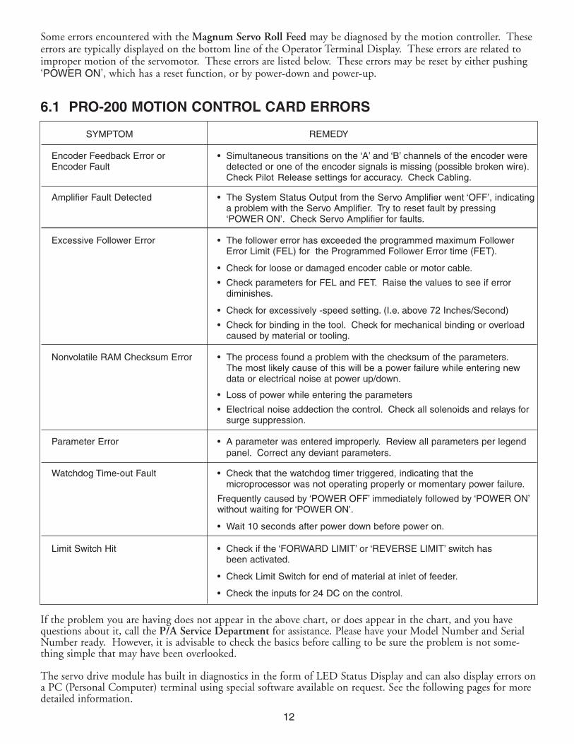
Some errors encountered with the Magnum Servo Roll Feed may be diagnosed by the motion controller. Theseerrors are typically displayed on the bottom line of the Operator Terminal Display. These errors are related toimproper motion of the servomotor. These errors are listed below. These errors may be reset by either pushing‘POWER ON’, which has a reset function, or by power-down and power-up.
6.1 PRO-200 MOTION CONTROL CARD ERRORS
If the problem you are having does not appear in the above chart, or does appear in the chart, and you havequestions about it, call the P/A Service Department for assistance. Please have your Model Number and SerialNumber ready. However, it is advisable to check the basics before calling to be sure the problem is not some-thing simple that may have been overlooked.
The servo drive module has built in diagnostics in the form of LED Status Display and can also display errors ona PC (Personal Computer) terminal using special software available on request. See the following pages for moredetailed information.
SYMPTOM REMEDY
Encoder Feedback Error or • Simultaneous transitions on the ‘A’ and ‘B’ channels of the encoder were Encoder Fault detected or one of the encoder signals is missing (possible broken wire).
Check Pilot Release settings for accuracy. Check Cabling.
Amplifier Fault Detected • The System Status Output from the Servo Amplifier went ‘OFF’, indicatinga problem with the Servo Amplifier. Try to reset fault by pressing‘POWER ON’. Check Servo Amplifier for faults.
Excessive Follower Error • The follower error has exceeded the programmed maximum Follower Error Limit (FEL) for the Programmed Follower Error time (FET).
• Check for loose or damaged encoder cable or motor cable.
• Check parameters for FEL and FET. Raise the values to see if error diminishes.
• Check for excessively -speed setting. (I.e. above 72 Inches/Second)
• Check for binding in the tool. Check for mechanical binding or overload caused by material or tooling.
Nonvolatile RAM Checksum Error • The process found a problem with the checksum of the parameters.The most likely cause of this will be a power failure while entering new data or electrical noise at power up/down.
• Loss of power while entering the parameters
• Electrical noise addection the control. Check all solenoids and relays for surge suppression.
Parameter Error • A parameter was entered improperly. Review all parameters per legend panel. Correct any deviant parameters.
Watchdog Time-out Fault • Check that the watchdog timer triggered, indicating that themicroprocessor was not operating properly or momentary power failure.
Frequently caused by ‘POWER OFF’ immediately followed by ‘POWER ON’without waiting for ‘POWER ON’.
• Wait 10 seconds after power down before power on.
Limit Switch Hit • Check if the ‘FORWARD LIMIT’ or ‘REVERSE LIMIT’ switch hasbeen activated.
• Check Limit Switch for end of material at inlet of feeder.
• Check the inputs for 24 DC on the control.
13
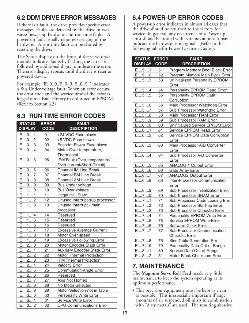
6.2 DDM DRIVE ERROR MESSAGESIf there is a fault, the drive provides specific errormessages. Faults are detected by the drive in twoways: power-up hardware and run-time faults. Apower-up fault usually requires servicing of thehardware. A run-time fault can be cleared byresetting the drive.
The Status display on the front of the servo drivemodule indicates faults by flashing the letter ‘E’,followed by additional digits to indicate the error.The error display repeats until the drive is reset orpowered down.
For example, ‘E..0..9..E..0..9..E..0..9..’ indicatesa Bus Under voltage fault. When an error occurs,the error code and the service time of the error islogged into a Fault History record stored in EPROM.(Refer to Section 6.3)
E....0....1 01 +24 VDC Fuse blownE....0....2 02 +5 VDC Fuse blownE....0....3 03 Encoder Power Fuse blownE....0....4 04 Motor Over temperature,
ThermostatE....0....5 05 IPM Fault (Over temperature/
Over current/Short Circuit)E....0....6 06 Channel IM Line BreakE....0....7 07 Channel BM Line BreakE....0....8 08 Channel AM Line BreakE....0....9 09 Bus Under voltageE....1....0 10 Bus Over voltageE....1....1 11 Illegal Hall StateE....1....2 12 Unused interrupt-sub processorE....1....3 13 Unused interrupt - main
processorE....1....4 14 ReservedE....1....5 15 ReservedE....1....6 16 ReservedE....1....7 17 Excessive Average CurrentE....1....8 18 Motor Over speedE....1....9 19 Excessive Following ErrorE....2....0 20 Motor Encoder State ErrorE....2....1 21 Auxiliary Encoder State ErrorE....2....2 22 Motor Thermal ProtectionE....2....3 23 IPM Thermal ProtectionE....2....4 24 Velocity ErrorE....2....5 25 Commutation Angle ErrorE....2....6 26 ReservedE....2....7 27 Axis Not HomedE....2....8 28 No Motor SelectedE....2....9 29 Motor Selection not in TableE....3....0 30 Personality Write ErrorE....3....1 31 Service Write ErrorE....3....2 32 CPU Communications Error
STATUS ERROR FAULTDISPLAY CODE DESCRIPTION
6.3 RUN TIME ERROR CODES
STATUS ERROR FAULTDISPLAY CODE DESCRIPTION
6.4 POWER-UP ERROR CODESA power-up error indicates in almost all cases thatthe drive should be returned to the factory forservice. In general, any occurrence of a Power-uperror should be treated with extreme caution. It mayindicate the hardware is marginal. (Refer to thefollowing table for Power-Up Error Codes).
E....5....1 51 Program Memory Boot Block ErrorE....5....2 52 Program Memory Main Block ErrorE....5....3 53 Uninitialized Personality EPROM
ErrorE....5....4 54 Personality EPROM Read ErrorE....5....5 55 Personality EPROM Data
CorruptionE....5....6 56 Main Processor Watchdog ErrorE....5....7 57 Sub Processor Watchdog ErrorE....5....8 58 Main Processor RAM ErrorE....5....9 59 Sub Processor RAM ErrorE....6....0 60 Uninitialized Service EPROM ErrorE....6....1 61 Service EPROM Read ErrorE....6....2 62 Service EPROM Data Corruption
ErrorE....6....3 63 Main Processor AID Converter
ErrorE....6....4 64 Sub Processor A/D Converter
ErrorE....6....5 65 ANALOG 1 Output ErrorE....6....6 66 Gate Array ErrorE....6....7 67 ANALOG2 Output ErrorE....6....8 68 Inter-Processor Communication
ErrorE....6....9 69 Sub Processor Initialization ErrorE....7....0 70 Sub Processor SRAM ErrorE....7....1 71 Sub Processor Code Loading ErrorE....7....2 72 Sub Processor Start-up ErrorE....7....3 73 Sub Processor Checklist ErrorE....7....4 74 Personality EPROM Write ErrorE....7....5 75 Service EPROM Write ErrorE....7....6 76 Software Clock ErrorE....7....7 77 Sub Processor Communication
Checklist ErrorE....7....8 78 Sine Table Generation ErrorE....7....9 79 Personality Data Out of RangeE....8....1 80 Service Data Out of RangeE....8....2 81 Motor Block Checksum Error
7. MAINTENANCEThe Magnum Servo Roll Feed needs very littlemaintenance to keep the system operating at itsoptimum performance.
• This precision equipment must be kept as cleanas possible. This is especially important if large amounts of air suspended oil mists in combinationwith “dirty metals” are used. The resulting abrasive

14
• The main drive belt should be checked periodicallyfor tightness. It can be adjusted by loosening the two fasteners on the motor adjuster plate, applying downward pressure on the motor adapter plate, and retightening. ERRATIC MOTORBEHAVIOR WILL BE EXPERIENCED IF THEDRIVE BELT IS LOOSE!
• All fasteners should be checked for tightness at regular intervals. The electrical system also requiresvery little maintenance. Keep the enclosure clean and replace any burned indicator bulbs. Do not expose the electrical enclosure to constant high temperatures. Possible system failure could result.
• The Feeder’s electrical enclosure door is sealed to prevent oil and contaminants from entering inside. However, small gaps can be found aroundsome sealing surfaces and faceplates. It is agood idea, therefore, to keep the console free of stamping oils and fluids, which could "seep into" the enclosure. Most often these oils arecarried by the operator’s hands or by air mist lubrication etc.
• All of the above guidelines should be added to your existing pressroom Preventive Maintenance (PM) Program.
8. ROLL FEED PARTS LIST & DIAGRAM
1 1 BEARING HOUSING - LEFT SIDE PLATE
2 1 BEARING HOUSING - RIGHT SIDE PLATE
3 1 PLATE- CASCADE MTG.
4 1 PLATE - FEED MTG.
5 1 PLATE - EXIT
6 1 PLATE - MATERIAL HOLD DOWN
7 1 BRACKET - UPPER ROLL, LEFT
8 1 BRACKET - UPPER ROLL, RIGHT
9 1 PLATE - UPPER ROLL
10 1 GUARD - ENTRY
11 1 ROLL - LOWER
12 2 DUST SHIELD - LOWER
13 1 SPACER - LOWER
14 2 BEARING - LOWER
15 1 GEAR - LOWER
16 1 ROLL - UPPER
17 2 DUST SHIELD - UPPER
18 2 RETAINING RING
19 2 BEARING - UPPER
20 1 GEAR - UPPER
21 1 SHAFT - THICKNESS ADJUSTMENT
22 1 LEVER - THICKNESS ADJUSTMENT
23 1 CAM ECCENTRIC BUSHING
24 1 BUSHING - TAPER LOCK - INNER
25 1 BUSHING - TAPER LOCK - OUTER
26 1 SHAFT - ROLL RELEASE
27 2 BEARING, NEEDLE
28 2 WEAR PAD
29 1 RELEASE LEVER - MANUAL
30 1 RELEASE LEVER - MECHANICAL
31 1 BEARING - ROLL RELEASE
32 1 SPACER - RELEASE BEARING
33 2 RETAINER, SPRING ROD
34 2 ROD, ROLL TENSION
ITEM QTY DESCRIPTION
35 2 SPRING, ROLL TENSION
36 1 SET SCREW M6 X 16
37 2 BRACKET - CASCADE
38 1 BLOCK - CASCADE MTG., LEFT
39 1 BLOCK - CASCADE MTG., RIGHT
40 1 PLATE - ENTRY
41 2 BAR - GUIDE ROLLER
42 2 CLAMP - GUIDE BAR
43 2 GUIDE ROLLER
44 4 SPACER - GUIDE ROLLER
45 2 NUT - T SLOT
46 3 ROLL - CASCADE, ENTRY
47 3 SHAFT - ROLL
48 10 BEARING - GUIDE & ENTRY ROLL
49 1 TRANSITION PLATE
50 1 ADJUSTMENT TAB
51 1 SCREW - HEX HD
52 1 NUT - HEX, JAM
53 1 KEY 22mm x 5mm x 110mm
54 2 KEY 22mm x 12mm x 40mm
55 1 STRIKER - RELEASE ACTUATOR
56 1 ARM - ADJUST
57 1 ARM - FIXED
58 1 BLOCK - MOUNTING
59 1 BRACKET - MOUNTING
60 1 NUT, STRIKER ADJUST
63 1 KEY 7mm SQ x 35mm
64 1 KEY 5mm SQ x 15mm
65 4 GREASE FITTING
67 4 NUT, M14, ROLL TENSION
68 1 COVER, FEED ROLLS – SRF-100
69 2 HANDLE, WIDTH GUIDE ADJUSTMENT
70 1 HANDLE, THICKNESS ADJUSTMENT
71 6 NUT, HEX
ITEM QTY DESCRIPTION

15
MAGNUM MECHANICAL PARTS DIAGRAM
SHEET 1 OF 4
76
100 PSI Pre-Plumbed
by P/A
Note: Use a good grade ofhydraulic oil like Shell Tellus 32.
Note: Pre-set at Factory.Do not adjust.
E See Sheet 4

16
SHEET 4 OF 4
VIEW AT E–EROTATED 90° DEGREES
VIEW AT F–FUPPER ROLL CROSS SECTION
WITH PIVOT MOUNTING ROTATED 90° DEGREES
VIEW AT G–GROTATED 90° DEGREES
VIEW AT A–ATOP COVER NOT SHOWN
VIEW AT B–B
VIEW AT C–C
TOP COVER
VIEW AT D–D
SHEET 3 OF 4
SHEET 2 OF 4

17
9. CASCADE WITHOUT ENCODER PARTS LIST & DIAGRAM
CASCADE WITHOUT ENCODER
1 D17443 2 BRACKET, CASCADE SIDE2 B17444-XX 1 ROD, AXLE-UPPER ROLL3 B16548-XX 3 ROD, AXLE-LOWER ROLLS4 A17093 2 CLAMP, GUIDE BAR5 A17091-XX 2 GUIDE BAR, EDGE ROLLERS6 C16542-XX 4 ROLLER, CONVEYOR
7 A17445-XX 4 COVER, ROLLER8 P12416-27 2 HANDLE, 12mm TAP9 M16522-2 2 ASSEMBLY, EDGE GUIDE ROLL21 16735-02 2 HANDLE, WIDTH GUIDE ADJUST.
Note: Part Numbers with “XX” designation are dependent on the Model width. Use numbers 12, 18, 24, 32, 36, or 48 respectively for Models M12, M18, M24, M32, M36, and M48.
ITEM PART NO. QTY DESCRIPTION ITEM PART NO. QTY DESCRIPTION
DRAWING 17441
PASS LINE

18
CASCADE WITH OPTIONAL ENCODER
10. CASCADE WITH ENCODER PARTS LIST AND DIAGRAM
1 D17443 2 BRACKET, CASCADE SIDE2 B17444-XX 1 ROD, AXLE-UPPER ROLL3 A16548-XX 3 ROD, AXLE-LOWER ROLLS4 A17093 2 CLAMP, GUIDE BAR5 A17091-XX 2 GUIDE BAR, EDGE ROLLERS6 C16542-XX 4 ROLLER, CONVEYOR7 A17445-XX 4 COVER, ROLLER8 M16522-02 2 ASSEMBLY, EDGE GUIDE ROLL9 P12416-27 2 HANDLE, 12mm TAP10 SUPPLIES 14 WASHER, 1/2” ID x 1.06 OD x .09 THK.11 SUPPLIES 14 NUT, M12 X 1.75 (DIN #934), PLATED12 SUPPLIES 2 SCREW, M6 X 1.0 X 30mm LONG,
SHCS, BLACK OXIDE13 SUPPLIES 6 SCREW, M10 X 1.5 X 25mm LONG,
SHCS, BLACK OXIDE
ITEM PART NO. QTY DESCRIPTION14 M16967 1 STRIP ENCODER15 C17183-XX 1 PLATE, ENCODER16 C17185-XX 1 PLATE, SUPPORT17 12110-20 1 VALVE, SELECTOR; 4-WAY18 A16987 1 PIPE PLUG, DRILLED19 SUPPLIES 2 SCREW, M8 X 1.25 X 60mm LONG,
BHCS, BLACK OXIDE20 SUPPLIES 2 SCREW, 10-32 X 1-1/2 BHCS
BLACK OXIDE21 16735-02 2 HANDLE, WIDTH GUIDE ADJUST.
Note: Part Numbers with “XX” designation are dependent on the Model width. Use numbers 12, 18, 24, 32, 36, or 48 respectively for Models M12, M18, M24, M32, M36, and M48.
ITEM PART NO. QTY DESCRIPTION
DRAWING 17442

19
Installation & Operating Manual
Programmable Limit Switch Job Set-Up
Typical Die Set-Up Chart
Die No. __________
Part No. _________
______ No. ______
Cam Function (Name) and Number “ON” Angle “OFF” Angle
#1 Feed Advance 235° 90°
#2 Continue Cam 180° 200°
#3 Pilot Release 150° 180°
#4
#5
#6
#7
#8
FEED DIRECTIO
N
360°0°
180°
Steel Coil ThicknessMfg. Std. Inch Equiv. Metric Equiv. DialGage No. for Steel Sheet mm Setting
– .2500 6.35 0063[5]3 .2391 6.07 0060[7]4 .2242 5.69 0056[9]5 .2092 5.31 0053[1]6 .1943 4.94 0049[4]– .1875 4.76 0047[6]7 .1793 4.55 0045[5]8 .1644 4.18 0041[8]9 .1495 3.80 0038[0]
10 .1345 3.42 0034[2]11 .1196 3.04 0030[4]12 .1046 2.66 0026[6]13 .0897 2.28 0022[8]14 .0747 1.90 0019[0]15 .0673 1.71 0017[1]16 .0598 1.52 0015[2]17 .0538 1.37 0013[7]18 .0478 1.21 0012[1]19 .0418 1.06 0010[6]20 .0359 0.91 0009[1]21 .0329 0.84 0008[4]22 .0299 0.76 0007[6]23 .0269 0.68 0006[8]24 .0239 0.61 0006[1]25 .0209 0.53 0005[3]26 .0179 0.45 0014[5]27 .0164 0.42 0004[2]28 .0149 0.38 0003[8]29 .0135 0.34 0003[4]30 .0120 0.30 0003[0]
Thickness Setting Chart
Continue Cam180°-200°Never Touch
PilotRelease150°-180°
90°270°
FeedAdvanceCam235°-90°

WARNINGThis equipment offers various means of operating orcontrolling machines. The operator must not be in ornear the point-of-operation of the machine, or theoperating parts of any equipment installed on themachine, or bodily injury could result. The EMPLOYERmust post adequate warning signs onto the machine withproper warnings for his machine and the specificapplication to which the machine and equipment arebeing applied.
Occupational Safety and Health Act (OSHA) Sections1910.211, 1910.212, and 1910.217 contain installationinformation on the distance between danger points andpoint-of-operation guards and devices. No specificreferences have been made to which paragraphof OSHA 1910.211, 1910.212, 1910.217, or any otherapplicable sections because the paragraphs may changewith each edition of the publication of OSHAprovisions.
All equipment manufactured by us is designed to meetthe construction standards of OSHA in effect at thetime of sale, but the EMPLOYER installs the equipmentso the EMPLOYER is responsible for installation, use,application, training, and maintenance, as well asadequate signs on the machine onto which thisequipment will be installed.
Remember, OSHA says that the EMPLOYER must useoperating methods designed to control oreliminate hazards to operating personnel.
It shall be the responsibility of the EMPLOYER toestablish and follow a program of periodic and regularinspections of his machine to insure that all their parts,auxiliary equipment, and safeguards are in a safeoperating condition and adjustment. Each machineshould be inspected and tested no less than weekly todetermine the condition of the machine. Necessarymaintenance or repair of both shall be performed andcompleted before the machine is operated. TheEMPLOYER shall maintain records of these inspectionsand the maintenance work performed.
Our Company is not responsible to notify the user ofthis equipment of future changes in State or Federallaws, or construction standards.
SAFETY PROGRAMAccident free operation will result from a well developed,management sponsored and enforced safety program.
Of vital importance to any successful program is theproper selection of guards and devices. However, there isno safety device that will bring "automatic" safety toyour operation.
Of equal importance to this proper selection of the guardand the device is the training of your personnel. Eachperson must be trained as to the operation of the guardor safety device, highlighting why they have beenprovided on the equipment. Rules for safe operatingshould be written and enforced at all times. A finalmajor concern of an effective safety program is regularlyscheduled inspection and maintenance of all of theequipment.
To ensure continued safety at all times, top management,line supervision, safety engineers and all employees mustassume their proper share of the responsibility in theprogram. Only as a group, one that knows your ownoperation and its problems, can you carry out aneffective safety program.
To assist you in the development of and continued useof safety programs, many safety minded groups havemade guidelines available to you. However, you mustknow when and how to apply these guidelines. Themanufacturer provides information to assist you inproperly adjusting and maintaining your equipment.There is no shortcut to proper safety; therefore, it isrecommended that you comply with theirrecommendations at all times.
WARRANTYWe warrant our new parts against defects under normaluse and service for a period of 12 months after date ofshipment. Our obligation under this warranty is limitedto replacing or repairing (at our option) the defectivepart without charge, Freight On Board (FOB) our plantin Bloomfield, Connecticut. The defective part must beforwarded to our plant, freight prepaid, for our inspectionprior to replacement or repair. EXCEPT AS EXPRESSLYPROVIDED HEREIN, THIS WARRANTY IS INLIEU OF ALL OTHER WARRANTIES, EXPRESSOR IMPLIED, INCLUDING A WARRANTY OFMERCHANTABILITY OR FITNESS FOR APARTICULAR PURPOSE. Furthermore, the seller doesnot warrant or represent that the equipment complieswith the provisions of any law, particularly including theOccupational Safety and Health Act of 1970, andregulations promulgated thereunder. In no event shall webe liable for special, indirect incidental or consequentialdamages, however rising.
20
P/A INDUSTRIES INC. 522 Cottage Grove Road • Bloomfield, Connecticut 06002-3191 U.S.A.Toll Free 1-800-243-8306 • Worldwide 1-860-243-8306 • Fax 1-860-242-4870Website http://www.pa.com • E-Mail [email protected]
FORM 1042 12-00

![3.3 LINEAR FEED ASSEMBLAGES · Fig. 3.3.2: Type execution example of the linear feed assemblage [Toshulin] through the ball screw. The rotary AC servo drive is connected to the ball](https://static.fdocuments.in/doc/165x107/5fb92888a3d1521376095257/33-linear-feed-fig-332-type-execution-example-of-the-linear-feed-assemblage.jpg)