
SERVO VENTILATOR 900 C OPERATING MANUAL ...frankshospitalworkshop.com/equipment/documents...General...
105
CRITICAL CARE SERVO VENTILATOR 900 C OPERATING MANUAL
-
Upload
nguyentuyen -
Category
Documents
-
view
225 -
download
2
Transcript of SERVO VENTILATOR 900 C OPERATING MANUAL ...frankshospitalworkshop.com/equipment/documents...General...

CRITICAL CARE
SERVO VENTILATOR 900 C
OPERATING MANUAL

▲! General information• Servo Ventilator 900 C must be operated only by authorized
personnel who are well trained in its use.It must be operated according to the instructions in thisOperating Manual.
• After unpacking, the ventilator must be checked and, ifnecessary, calibrated.
• All data on pressures for Servo Ventilator 900 C are given incm H2O.1 kPa (kilopascal) ≈ 10 cm H2O100 kPa = 1 bar ≈ 1 atm ≈ 1 kgf/cm2 (kp/cm2)100 kPa ≈ 15 psi
• Responsibility for the safe functioning of the equipmentreverts to the owner or user in all cases in which service orrepair has been done by a non-professional or by personswho are not employed or authorized by MAQUET, and whenthe equipment is used for other than its intended purpose.
• A full technical description – including circuit diagrams, partslist and service data – is contained in the servicedocumentation, copies of which are held by your supplier.
Connection• When connected to a patient, the ventilator must never be
left unattended.• A check on functions must be done before a patient is
connected to the ventilator.• When anaesthetic gas is metered via a flow meter on the low
pressure inlet, compressed air must not be connected at thesame time.
• To avoid explosion hazards, flammable agents such as etherand cyclopropane must not be used in this machine. Onlyagents which comply with the requirements on non-flammable agents in the IEC standard “Particularrequirements for electrical safety of anaesthetic machines”are suitable in this machine.
• As this machine is not suitable for use with flammable agentssuch as ether and cyclopropane, the use of antistaticbreathing tubes and face masks is not necessary.The use of antistatic or electrically conductive breathingtubes when using high frequency electric surgery equipment,may cause burns and is therefore not recommended in anyapplication of this machine.
• Never connect or disconnect auxiliary equipment to the outleton the rear of the ventilator when the ventilator is connectedto mains.
• All gases must fulfill the specifications for medical grade gas.The gases supplied must be dry and free from oil and dust.Air H2O < 5 g/m3
Oil < 0.5 mg/m3
Oxygen H2O < 20 mg/m3
Nitrous oxide/gaseous phase) H2O < 58 ppm
Operation• The APNEA ALARM is not intended to and will not monitor
for disconnections.• The APNEA ALARM is not functional in VOL. CONTR., VOL.
CONTR. + SIGH, PRESS. CONTR. or MAN.• In the case of a power failure, manual ventilation using a
Servo Ventilator 900 C is possible only with the help ofpower supply from external battery. A resuscitator shouldalways be available, however, as an extra safety measure.
• The SV 900 C is certified, with regard to safety, to becompatible with electromagnetic environments complyingwith IEC 601-1-2. It is the responsibility of the user to takenecessary measures in order to ascertain that the specifiedlimits are not exceeded as this may impair the safety of theventilator.Such measures should include, but are not limited to:– normal precautions with regard to relative humidity andconductive characteristics of clothing in order to minimize thebuild-up of electrostatic charges.– avoiding the use of radio emitting devices in close
proximity of the ventilator, such as high-frequency surgeryapparatus or cordless (mobile) telephones, resulting in a fieldlevel exceeding 3 V/m (IEC 601-1-2).Magnetic fields of MR equipment having flux densities above20 mT may cause deactivation of the ventilator functions andmay result in permanent damage to the Servo Ventilator.
• To protect the patient against high pressures, the WORKINGPRESSURE and UPPER PRESS. LIMIT must always be setat suitable values.
• Do not forget to set the manual ventilation valve to positionAUT after completed manual ventilation. Otherwise thepatient may be hypoventilated without any alarm from theventilator. (Not applicable to manual ventilation accessorywith motor).
• When mains supply is switched off or in the case of a mainspower failure, the inspiratory and expiratory valves willautomatically open. This may also occur in the case of aninternal electronic failure. Thus, if the WORKINGPRESSURE is set too high and the gas supply through thegas supply unit continues, this may result in increased airwaypressure.
• When excess gas is being scavenged, the scavengingsystem must meet the following requirements:– At the point at which the scavenging system isconnected to the ventilator, the sub-atmospheric pressuremust not exceed 0.5 cm H2O or cause an induced flow fromthe breathing system greater than 0.5 l/min.– With continuous air flows of 30 l/min and 90 l/min fornot less than 5 seconds at the inlet of the anaestheticgas scavenging system, the resistance in the systemshall not exceed 0.25 cm H2O and 2.5 cm H2O, respectively.The Servo Evac 180 basic evacuation unit meets theserequirements.
• If the ventilator is equipped with electronic gas supply unit,the following applies:When mains supply is switched off or in the case of powerfailure, the gas supply is automatically blocked.
Cleaning• The ventilator must not be gas sterilized.• The flow transducers must not be cleaned in a dish washing
machine, by ultrasonic methods or by using agents thatcontain aldehydes.
• Agents used for cleaning must have a pH value between4–8.5.
• Complete cleaning should be done after every 1000 hoursof operation or, at the latest, after every six months.
Service• The Servo Ventilator 900 C must be serviced at regular
intervals by specially trained personnel. Any maintenancemust be noted in the log book provided for that purpose,in accordance with national regulations. We recommend thatservice is done as a part of a service contract with MAQUET.
• The 1000 hours overhaul shall be done after every 1000operating hours or, at the latest, every six months. Inaddition, the ventilator shall undergo a technical safety checktwice a year, at six months intervals, according to nationalregulations.
• Service and repairs on the ventilator may be done onlyby MAQUET authorized personnel.
• Only original parts from MAQUET must be used in theventilator.
Equipment combinations• Only MAQUET-approved accessories and auxiliary
equipment may be connected to the ventilator.• In order to maintain system safety and integrity only
accessories complying with IEC 601-1, or the safety of whichhas been verified in another way must beconnected to the signal outputs on the rear of the ventilator.For details on connections and allowedvoltages, please see Circuit Diagram.
Important

Product information program
This Operating Manual is a part of a comprehensiveinformation program for Servo Ventilator 900 C.The program is planned to contain the following:
Promotional and Scientific Publications
Operating and Service Instructions
Product Training Material
Brochure Servo Application Product Leaflet ReprintsVentilator Brochures:Concept Intensive Care
AnesthesiaTransportation
Operating Brief Wall Diagram Service Manual Circuit DiagramManual Operating with Cleaning
Instructions Instructions
Training Advisory Slide Series “I am breathing The Patient’sInstructions Booklet including through a ABSee®
for Instructors Textbook ventilator” CardsFilm and and PosterBooklet
Front Panel Panel Block Trainee’s set Video programsFlip-chart Video guide
Video news

Servo Ventilator 900 C-Front


Servo Ventilator 900 C is simple to operate.Operating instructions are found:
!
On the ventilator in the form of a panel andcleaning instructions on the lid of thepneumatic unit.
“Normal” settings are indicated in green onthe front panel. Settings indicated in redshould be used with caution, since thesesettings may involve a certain risk for thepatient.
@
In the Brief Operating Instructions in the drawerunder the ventilator.
A log sheet is available with the BriefOperating Instructions. After certain routines,e. g. cleaning etc., the person responsible forthe work should complete and sign the logsheet. The log sheet can then be filed.
#
On a separate wall poster with cleaninginstructions.
$
In this Operating Manual.The inside of the cover shows a picture of
the ventilator. This picture can be used as afoldout when reading the manual.
The following information is found in thecorresponding chapters:
Description ............................................ 1-3
Operating ............................................... 4-9
Maintenance ...................................... 10-13
Technical specifications ......................... 14
Operating instructions

1
1. Arbetsprincip
2. Kontrollpanel och ventilationssätt
3. Patientsäkerhet
4. Uppställningar
5. Förberedelser
6. Funktionskontroll
7. Anslutning till patient
8. Klinisk bedömning och felsökning
9. Registrering
10. Rutinrengöring
11. 1000-tim.-översyn med fullständig rengöring
12. Utbyte av O2-cell
13. Kalibrering
14. Tekniska specifikationer
Contents
1. Basic principles
2. Control panel and ventilation modes
3. Patient safety
4. Set-ups
5. Preparations
6. Check on functions
7. Connection to patient
8. Clinical judgement and troubleshooting
9. Recording
10. Routine cleaning
11. 1000 hours overhaul with complete cleaning
12. Replacement of O2 cell
13. Calibration
14. Technical specifications

2

11Basic principles
In this chapter:
General design .................1:2Pneumatic unit..................1:3Rear ...................................1:4
Chapter 1

12
General design
Low pressure
High pressure
Pneumatic unitThe pneumatic unit comprises the gasconduction system, pressure and flowtransducers and control valves.
The control of flow and pressure is done by afeed-back system. The transducers continuallymeasure the flow and pressures. Theinformation is compared with the panel settingsand a difference between the actual and thepreset values results in correction signals tothe control valves.
For detailed description, see chapter “Basicprinciples” in the Training Instructions.
Electronic unitThe electronic unit contains a number of plug-in PC-boards with the circuits for regulation,alarms and monitoring.
The unit effects the electronic control of thepneumatic unit.
Servicing of the ventilator is facilitated by thespare parts exchange system. The faulty partsare replaced by factory trimmed exchangeparts.
Service on the electronic unit must be doneby MAQUET, or by MAQUET authorizedpersonnel only.

31
Pneumatic unit
!Gas connection. The upper inlet, not visible inthe picture, is used for low pressure gas andthe lower inlet is used for high pressure gas.For anaesthesia, a gas supply unit with threeinlets is available.
@The gas supply is regulated by a valve so that aconstant pressure is maintained in the bellows.
#The O2 cell measures the O2 concentration inthe gas.
$The gas flows through a bacteria filter.
%The respiratory gases are mixed and stored ata constant pressure in the bellows.
^The working pressure is set with an adjustmentscrew.
&A manometer shows the working pressure.
*A safety valve opens if the bellows is overfilled,or if the pressure exceeds approx. 120 cm H2O.
(The flow transducer on the inspiration sidemeasures the gas flow to the patient.
BLThe inspiration valve regulates the inspiratorygas flow. It is closed during the pause andexpiratory parts of the respiratory cycle.
BMThe pressure transducer on the inspiration sidemeasures the airway pressure.
BNThe flow transducer on the expiration sidemeasures the gas flow from the patient.
To prevent condensation, the transducer isheated to approx. 60°C.
BOThe pressure transducer on the expiration sidemeasures the airway pressure.
BPThe expiration valve is closed duringinspiration. During the expiratory phase it iseither fully open or regulating the PEEP level.
BQThe flap valve prevents a back flow of exhaledgases. It is also necessary for the trigg function.

14
Rear
Rear ofServo Ventilator 900 CTo the right on the electronic unit are the mainsinlet socket, fuse holders, On/Off switch,voltage rating, equipotential socket andoperating time meter.
To the left on the electronic unit are three15-pole sockets for auxiliary equipment.
The 37-pole socket is used for recording ofpressure and flow curves.
There are labels with the serial number of theapparatus on both the pneumatic unit and theelectronic unit.
Control terminalUnder the secured lid, there is a connector forexternal control of ventilation.
For details see separate Operating Manual.
Outputs forauxiliaryequipment
Controlterminal
Recorderoutput
Mains inlet socket
Operating time meter
Equipotential socket
On/Off switch
Fuse holders

1212
Chapter 2
Control panel andventilation modesIn this chapter:
Panel designand symbols ................... 2:2Panel functions............... 2:3Working pressure ........... 2:3Mode selection ............... 2:3Respiratory pattern ........ 2:4I:E ratio ............................ 2:5Expired minute volume .. 2:6Special functions............ 2:7Airway pressure ............. 2:8SIMV ................................ 2:10O2 alarm........................... 2:11Parameter selection ....... 2:11Controlled ventilation .... 2:12Supported ventilation .... 2:13Spontaneous ventilation. 2:15Manual ventilation .......... 2:16

22
Panel design and symbols
For easy operation, the panel is divided intofields. Each field is described in this chapter.
“Normal” settings are indicated in green onthe front panel. Settings indicated in red shouldbe used with caution since these settings mayinvolve a certain risk for the patient.
A number of knobs and the EXPIREDMINUTE VOLUME meter have dual scales.
The blue scale is always to be used when thelow range is selected.
Power on is indicated by a green lamp.A yellow lamp is either an indication of a
certain setting or a reminder to set an alarmlimit.
A red lamp always indicates an alarm.
! Working Pressure
@ Mode Selection
# Respiratory Pattern
$ Expired Minute Volume
% Special Functions
^ Airway Pressure
& SIMV
* O2 Concentration Alarm
( Monitoring

32
Panel functions
Working pressureThe working pressure is set with an adjustmentscrew and is read on the manometerWORKING PRESSURE.
The working pressure must always be set ata value somewhat higher than the highestairway pressure.
Mode selectionThe Servo Ventilator 900 C can be operated in8 different modes, which are selected by meansof the mode selector.
The modes are described in special sectionsin this chapter.
Controlled ventilationVolume controlled ventilation (VOL. CONTR.)Volume controlled ventilation + sigh (VOL.CONTR. + SIGH)Pressure controlled ventilation (PRESS.CONTR)
Supported ventilationPressure supported ventilation (PRESS.SUPPORT)SIMV (Synchronized Intermittent MandatoryVentilation)SIMV + Pressure support (SIMV + PRESS.SUPPORT)
Spontaneous ventilationCPAP (Continuous Positive Airway Pressure)
Manual ventilationMAN
24
20
30
4050 60 70
80
90
100
110
120
25 5033
INSP. TIME %BREATHS/min
PRESET INSP. MIN. VOL./min
PAUSE TIME 10 %(INSP. PAUSE)
Panel functions
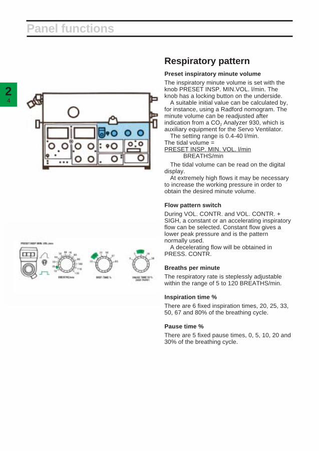
Respiratory patternPreset inspiratory minute volumeThe inspiratory minute volume is set with theknob PRESET INSP. MIN.VOL. l/min. Theknob has a locking button on the underside.
A suitable initial value can be calculated by,for instance, using a Radford nomogram. Theminute volume can be readjusted afterindication from a CO2 Analyzer 930, which isauxiliary equipment for the Servo Ventilator.
The setting range is 0.4-40 l/min.The tidal volume =PRESET INSP. MIN. VOL. l/min
BREATHS/minThe tidal volume can be read on the digital
display.At extremely high flows it may be necessary
to increase the working pressure in order toobtain the desired minute volume.
Flow pattern switchDuring VOL. CONTR. and VOL. CONTR. +SIGH, a constant or an accelerating inspiratoryflow can be selected. Constant flow gives alower peak pressure and is the patternnormally used.
A decelerating flow will be obtained inPRESS. CONTR.
Breaths per minuteThe respiratory rate is steplessly adjustablewithin the range of 5 to 120 BREATHS/min.
Inspiration time %There are 6 fixed inspiration times, 20, 25, 33,50, 67 and 80% of the breathing cycle.
Pause time %There are 5 fixed pause times, 0, 5, 10, 20 and30% of the breathing cycle.
52
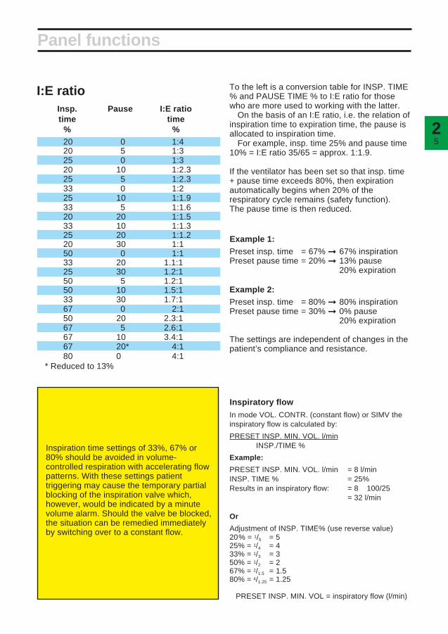
Panel functions
I:E ratioInsp. Pause I:E ratiotime time
% %20 0 1:420 5 1:325 0 1:320 10 1:2.325 5 1:2.333 0 1:225 10 1:1.933 5 1:1.620 20 1:1.533 10 1:1.325 20 1:1.220 30 1:150 0 1:133 20 1.1:125 30 1.2:150 5 1.2:150 10 1.5:133 30 1.7:167 0 2:150 20 2.3:167 5 2.6:167 10 3.4:167 20* 4:180 0 4:1
* Reduced to 13%
Inspiratory flowIn mode VOL. CONTR. (constant flow) or SIMV theinspiratory flow is calculated by:
PRESET INSP. MIN. VOL. l/minINSP./TIME %
Example:
PRESET INSP. MIN. VOL. l/min = 8 l/minINSP. TIME % = 25%Results in an inspiratory flow: = 8 × 100/25
= 32 l/min
Or
Adjustment of INSP. TIME% (use reverse value)20% = 1/5 = 525% = 1/4 = 433% = 1/3 = 350% = 1/2 = 267% = 2/1.5 = 1.580% = 4/1.25 = 1.25
× PRESET INSP. MIN. VOL = inspiratory flow (l/min)
To the left is a conversion table for INSP. TIME% and PAUSE TIME % to I:E ratio for thosewho are more used to working with the latter.
On the basis of an I:E ratio, i.e. the relation ofinspiration time to expiration time, the pause isallocated to inspiration time.
For example, insp. time 25% and pause time10% = I:E ratio 35/65 = approx. 1:1.9.
If the ventilator has been set so that insp. time+ pause time exceeds 80%, then expirationautomatically begins when 20% of therespiratory cycle remains (safety function).The pause time is then reduced.
Example 1:Preset insp. time = 67% ➞ 67% inspirationPreset pause time = 20% ➞ 13% pause
20% expiration
Example 2:Preset insp. time = 80% ➞ 80% inspirationPreset pause time = 30% ➞ 0% pause
20% expiration
The settings are independent of changes in thepatient’s compliance and resistance.
Inspiration time settings of 33%, 67% or80% should be avoided in volume-controlled respiration with accelerating flowpatterns. With these settings patienttriggering may cause the temporary partialblocking of the inspiration valve which,however, would be indicated by a minutevolume alarm. Should the valve be blocked,the situation can be remedied immediatelyby switching over to a constant flow.

26
Expired minute volumeEXPIRED MINUTE VOLUME is indicated on ameter which has dual scales: 0-40 l/min and 0-4 l/min.
The scale 0-4 l/min is intended for use whengreater accuracy, e. g. for infants, is needed.
The knobs for LOWER ALARM LIMIT andUPPER ALARM LIMIT also have the samedual scales.
The end stop positions for the knobs do notcoincide with the end positions on the scale.This is correct and no attempt should be madeto alter the range.
The desired scale is selected with the switchINFANTS/ADULTS.
The alarm limits for expired minute volumemust always be set. If either of the knobs hasbeen set in end position (out of scale), theyellow lamp SET MIN. VOL. ALARM flashes.The alarm limits are normally set at approx.20% below and above the selected minutevolume. The upper limit may be set at approx.30% above the selected minute volume in themode VOL. CONTR. + SIGH.
The APNEA ALARM is activated with audiblesignals and flashing light if the time betweenany two consecutive breaths, spontaneous ormandatory or a combination of the two, isgreater than approximately 15 seconds(4 breaths per minute or less). The APNEAALARM is not intended to and will not monitorfor disconnections. The APNEA ALARM isoperative in CPAP, PRESS. SUPPORT, SIMVand SIMV + PRESS. SUPPORT.
Failure of gas supply to the ventilator willresult in visual and audible GAS SUPPLYALARM signals. The GAS SUPPLY ALARM isnot operative at respiratory rates over 80breaths/min., and INSP. TIME % 20 or 25.
Panel functions

72
Special functionsUnder the small hood below the UPPERALARM LIMIT knob are three pushbuttons forspecial functions.
Inspiratory pause holdWhen the pushbutton INSP. PAUSE HOLD isdepressed, the valves close after inspirationand the pause is prolonged as long as thepushbutton is depressed.
This provides an exact measurement of theend inspiratory lung pressure. It may also givetime for an equilibration of the blood gas andalveolar pressures.
Expiratory pause holdThe valves are closed, after the expiration, aslong as the pushbutton EXP. PAUSE HOLD isdepressed, i.e. a prolonged expiratory pause.This provides an exact measurement of theend expiratory lung pressure.
Panel functions
EXP. PAUSE HOLD must not be used inSIMV or SIMV + PRESS. SUPPORT mode.Two inspirations may occur at the sametime. However, the UPPER PRESS. LIMITis still functional.
Gas ChangeThe pushbutton GAS CHANGE is used, forinstance, when it is desirable to rapidly alter thegas mixture to the patient. The concentrationsetting on the vaporizer/gas mixer/flowmetersmust be altered first.
The inspiration and expiration valves open sothat the pressure in the patient circuit is max.20 cm H2O.
During the gas changing time, the EXPIREDMINUTE VOLUME meter is zeroedautomatically.
INSP. EXP. GASPAUSE PAUSE CHANGEHOLD HOLD
28
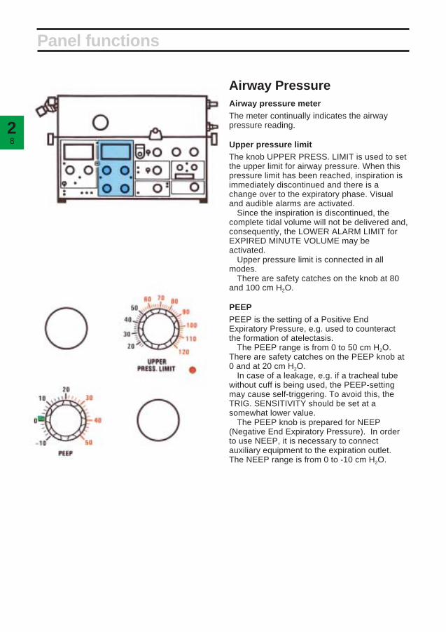
Airway PressureAirway pressure meterThe meter continually indicates the airwaypressure reading.
Upper pressure limitThe knob UPPER PRESS. LIMIT is used to setthe upper limit for airway pressure. When thispressure limit has been reached, inspiration isimmediately discontinued and there is achange over to the expiratory phase. Visualand audible alarms are activated.
Since the inspiration is discontinued, thecomplete tidal volume will not be delivered and,consequently, the LOWER ALARM LIMIT forEXPIRED MINUTE VOLUME may beactivated.
Upper pressure limit is connected in allmodes.
There are safety catches on the knob at 80and 100 cm H2O.
PEEPPEEP is the setting of a Positive EndExpiratory Pressure, e.g. used to counteractthe formation of atelectasis.
The PEEP range is from 0 to 50 cm H2O.There are safety catches on the PEEP knob at0 and at 20 cm H2O.
In case of a leakage, e.g. if a tracheal tubewithout cuff is being used, the PEEP-settingmay cause self-triggering. To avoid this, theTRIG. SENSITIVITY should be set at asomewhat lower value.
The PEEP knob is prepared for NEEP(Negative End Expiratory Pressure). In orderto use NEEP, it is necessary to connectauxiliary equipment to the expiration outlet.The NEEP range is from 0 to -10 cm H2O.
Panel functions

92
Trig. sensitivityThe knob TRIG. SENSITIVITY is used to setthe value of negative pressure that the patientmust produce in order to trigger a breath.
The TRIG. SENSITIVITY is relative to PEEP.For instance, PEEP +10 and TRIG.SENSITIVITY -2 cm H2O mean that the patientmust produce a pressure of -2 cm H2O relativeto the setting to trigger a breath.
This corresponds to a pressure of +8 cm H2Orelative to atmospheric pressure in the patient’sairways.
The airway pressure, measured on theexpiration side, is compared with the presetTRIG. SENSITIVITY + PEEP. If the airwaypressure drops below TRIG. SENSITIVITY +PEEP, a breath is triggered.
If it is desirable for the patient to be able toeasily trigger the ventilator, the knob is set atgreen value.
If it is undesirable for the patient to be able totrigger the ventilator, the knob is set at-20 cm H2O.
Trig. sensitivity is connected in all modesexcept MAN. For further details, seedescription on different modes.
Inspiratory pressure levelThe knob INSP. PRESS. LEVEL is used to setthe constant inspiratory pressure, relative toPEEP, when any of the following modes ofventilation are used: PRESS. CONTR.,PRESS. SUPPORT, SIMV + PRESS.SUPPORT.
A safety catch is located at 30 cm H2O.
Panel functions
The total inspiratory pressure level alsoincludes PEEP. This is why there is amarking under the PEEP knob leading tothe INSP. PRESS. LEVEL knob. At a PEEPof +5 cm H2O and an INSP. PRESS.LEVEL of +15 cm H2O, the total inspiratorypressure level would be +20 cm H2O,relative to atmospheric pressure.

210
Panel functions
SIMVSIMV (Synchronized Intermittent MandatoryVentilation) means that the patient getsmandatory breaths controlled by the ventilator,and that he also has the possibility of breathingspontaneously.
The mandatory breaths are synchronizedwith the breaths of the patient so that he neednot breathe against the ventilator.
SIMV-rate (SIMV BREATHS/min) is the rateof the mandatory breaths per minute. The rateis set between 0.4 and 4 breaths per minute onthe LOW RATE scale, and between 4 and 40breaths/min on the HIGH RATE scale. Thedesired rate is selected by means of a switch.There are two indicating lamps, one for eachrate.
The tidal volume and the frequency can beread on the digital display.
The SIMV cycle is divided into SIMV period andspontaneous period. See page 2:14.
Minute volume, respiratory rate, inspirationtime and pause time must be set for theSIMV mode. These functions determine therespiratory pattern of the mandatorybreaths. The BREATHS/min must alwaysbe set higher than the SIMV BREATHS/minto allow time for the spontaneous period.

112
O2 alarmAlarm limits for O2 concentration are set with theknobs UPPER ALARM LIMIT and LOWERALARM LIMIT. The SET O2 ALARM flashes if thealarm limits have not been set.
The end stop positions for the knobs do notcoincide with the end positions on the scale.This is correct and no attempt should be made toalter the range.
The alarm limits are set as follows:• Set O2 concentration on the gas mixer/
flowmeters.• Set the parameter selector at O2 CONC. %
and read the value.• Set the alarm limits at approx. 6% by volume
(3 scale divisions) below and above the O2
concentration reading on the digital display.Visual and audible alarms are activated when
any of the alarm limits is exceeded.If the O2 cell is expended but still mounted in
the ventilator, the O2 cell has to be disconnected.If not, the LOWER ALARM LIMIT will activatealarm.
If no O2 cell is mounted, neither digital displaysnor alarm is activated when the parameterselector is set at O2 CONC. %.
Parameter selectionA digital display of the O2 concentration is givenwhen the selector is set in position O2 CONC. %.
Other displayable parameters are:INSPIRED TIDAL VOLUME ml—the volume
provided by the ventilator at each breath.EXPIRED TIDAL VOLUME ml—the volume
produced by the patient at each breath (with noleakage in the patient circuit).
EXPIRED MINUTE VOLUME l/min—(alsoindicated on the EXPIRED MINUTE VOLUMEmeter).
PEAK PRESSURE cm H2O—the pressure atthe end of the inspiration phase.
PAUSE PRESSURE cm H2O—the pressure atthe end of the pause. This pressure normallycorresponds to the maximal alveolar pressure inthe lungs.
MEAN AIRWAY PRESSURE cm H2O—themean value in the patient circuit, continuallymeasured.
BREATHS/min—the respiratory rate of thepatient. In controlled ventilation, this valueequals the set respiratory rate plus eventualpatient triggered breaths. In the SIMV mode, it isthe sum of the spontaneous and the mandatorybreaths. In the CPAP and PRESSURESUPPORT modes, the value represents thespontaneous breaths/min of the patient.
Panel functions

212
Controlled ventilation
Volume controlled ventilationVolume controlled ventilation (VOL. CONTR.)ensures that the patient receives a certain presettidal volume.
Servo Ventilator 900 C delivers a specific tidalvolume at a specific rate during a specific time(preset values).
If the patient makes inspiratory efforts so thatthe airway pressure falls below the triggeringlevel, a preset tidal volume will be deliveredearlier and the expired minute volume willincrease.
A constant or an accelerating flow can beselected.
A patient trigg initiates a breath with the presetvalues.
Volume controlled ventilation+ sighIn this mode of operation, the Servo Ventilator900 C delivers a sigh every hundredth breath.At sigh, double tidal volume is delivered sincethe flow is constant and the inspiration time isdoubled.
The first sigh will occur at the secondinspiration after setting the mode selector toVOL. CONTR. + SIGH.
The UPPER ALARM LIMIT for EXPIREDMINUTE VOLUME may have to be setsomewhat higher in this mode.
Pressure controlledventilationIn the mode PRESS. CONTR., gas is deliveredat a constant pressure during the set inspirationtime.
The pressure is set with the knob INSP.PRESS. LEVEL.
The flow is decelerating in this mode.The set inspiratory pressure, respiratory rate,
and inspiration time determine the volume thepatient will receive.
Servo Ventilator 900 C works with a constantpressure during the entire inspiration.
The minute volume can be read on theEXPIRED MINUTE VOLUME meter.
Tidal volume can be read on the digital displaywith the parameter selector in position INSP.TIDAL VOLUME or EXP. TIDAL VOLUME.
In case of leakage in the system, e.g. due tothe use of a tracheal tube without cuff, a pausetime of 0% is recommended to ensure that themeasurement of the expired minute volume willbe as correct as possible.
A patient trigg initiates a breath with the presetvalues.
WORKING PRESSURE and UPPERPRESS. LIMIT must always be set atadequate values. This is extremelyimportant when treating infants.
Sigh
l/s
cm
H2O
Insp. Exp.Pau
se
Flo
w P
ress
ure
Flo
w
Pre
ssur
eF
low
P
ress
ure

132
Supported ventilation
Pressure supportedventilationPRESS. SUPPORT is a spontaneous breathingmode in which the patient must trigger breaths.
Some applications for PRESS. SUPPORTare: weaning, patients suffering from asthmaor, in post-operative use, when the patient’sown breathing efforts are insufficient.
When the patient triggers the ventilator, aninspiration pressure support is given at a presetconstant pressure.
The ventilator regulates the pressure duringinspiration so that it corresponds to presetINSP. PRESS. LEVEL + PEEP.
The pressure during expiration drops to0 cm H2O, or alternatively to PEEP-level.
The change from inspiration to expirationoccurs when the flow decreases to 25% of thepeak inspiratory flow.
There are also safety functions to control thechange from inspiration to expiration, forinstance in the case of a leakage.
Expiration will then start when the step motorhas closed the inspiratory valve and the airwaypressure has increased to +3 cm H2O abovethe preset INSP. PRESS. LEVEL + PEEP orafter 80% of the preset respiratory cycle.Because of this safety function the respiratoryrate should always be set with the knobBREATHS/min.
Flo
wP
ress
ure
Trig.

214
Supported ventilation
!A patient trig. during the SIMV period initiates amandatory breath. After that, spontaneousbreathing.
@During the SIMV period no breath has beentriggered. The next period begins with amandatory breath. After that, spontaneousbreathing.
SIMVSIMV (Synchronized Intermittent MandatoryVentilation) means that a preset number ofbreaths are ventilator controlled, mandatorybreaths (SlMV BREATHS/min). The patientmay breathe spontaneously between thosebreaths.
Breathing pattern and tidal volume for themandatory breaths are selected with the knobsPRESET INSP. MIN. VOL., BREATHS/min,INSP. TIME % and PAUSE TIME %.
The time in seconds for one SIMV cycle iscalculated from the formula
60preset SIMV freq.The SIMV cycle is divided into SIMV period
and spontaneous period.The spontaneous period consists of
spontaneous breathing time if the patient hastriggered a mandatory breath during theprevious SIMV period.
If the patient has insufficient spontaneousbreathing, the maximum time between twomandatory breaths is just over one SIMV cycle,(cp 1 to 2 in the picture above).
To ensure adequate ventilation, apnea alarm isactivated if the time between two breathsexceeds approx. 15 sec., and the minute volumealarm is activated if any of the preset alarm limitsis exceeded.
Either of these alarms is a command to takethe necessary action (e.g. clinical judgement ofthe patient, increased SIMV frequency, alteredtrig. sensitivity).
The SIMV period is approx. equal to onerespiratory cycle.
The spontaneous period is calculated as SIMVcycle-SIMV period.
Example:BREATHS/min 15 ➞ SIMV period = 60 = 4 s
15SIMV BREATHS/min 6 ➞ SIMV cycle = 60 = 10 s
6Spontaneous period ➞ 10-4 = 6 s
A patient trig during the SIMV period initiates abreath with the preset values. A patient trigduring the spontaneous period opens theinspiratory valve, and the patient can breathethrough the ventilator.
Flo
wP
ress
ure
SIMV cycle 10 s SIMV cycle 10 s
SIMV period 4 s Spontaneous period 6 sSpontaneous period 6 sSIMV period 4 s

152
SIMV + pressure supportThe main difference between this mode and theSIMV mode is that the spontaneous, triggeredbreaths are pressure supported.
The level of support is set with the controlINSP. PRESS. LEVEL. The level also includesPEEP.
See also description of pressure support onpage 2:13.
Care should be taken in setting the presetBREATHS/min, so that the spontaneouspressure-supported breaths are notprematurely time-cycled rather than flow-cycled to expiration.
Spontaneous ventilationCPAPIn this mode, CPAP (Continuous Positive AirwayPressure), the patient breathes spontaneouslythrough the ventilator at an elevated pressurelevel. The positive pressure is set with thePEEP control.
The TRIG. SENSITIVITY control must be setat a position which allows the patient to triggerthe ventilator. Upon triggering, the inspirationvalve opens, and the patient can inspire throughthe ventilator and control the tidal volume andrespiratory rate.
To avoid self-triggering due to leakage, thetrig. level should be set at a low value.
If CPAP (PEEP) = 0, it will be possible tocheck the patient’s ability to breathespontaneously without help from the ventilator.
The minute volume, tidal volume andrespiratory rate can be monitored.
Supported and spontaneous ventilation
These settings determinethe SIMV period.This setting determines theSIMV cycle.
Flo
w
Pre
ssur
e
SIMV cycle 10 s
SIMV cycle
Flo
w
Pre
ssur
e
Mandatory breath Pressure supportedspontaneous breaths
Flo
w
Pre
ssur
e
TRIG. SENSITIVITY
PEEP
SIMVperiod 4 s
Spontaneousperiod 6 s
SIMV period Spontaneous periodINSP. PRESS. LEVEL
0 or PEEP-levelTRIG. SENSITIVITY

216
MAN AUT
MAN AUT
Always set UPPER PRESS. LIMIT at thelowest possible value for normal operation.
The APNEA alarm is inoperative duringmanual ventilation.
In the case of a power failure, manualventilation is not possible unless anexternal power pack is connected.
PEEP cannot be used in manualventilation mode.
Set the mode selector to VOL. CONTR.immediately before connecting theventilator to a patient. The reason is to zerothe gas flow reading.
At spontaneous breathing during manualventilation the following readings will beincorrect.– the displayed values for BREATHS/min.,
EXP. TIDAL VOLUME and EXP.MINUTE VOLUME.
– the alarm monitoring instrumentEXPIRED MINUTE VOLUME.The accuracy of the EXPIRED MINUTE
VOLUME meter reading decreases. Afterabout 5 minutes, the accuracy is about±2 l/min. To get a correct meter reading,the breathing bag should be squeezed atleast every 5 minutes.
For spontaneous breathing, thePRESSURE SUPPORT mode isrecommeded. The INSP. PRESS. LEVELshould be set at zero or at a low value. Thisenables continuous monitoring of pressureand volume.
Manual ventilation
Manual ventilationThe Manual Ventilation Accessory with Motorconsists of two units:• Electronic unit• Motor/valve unit
With this accessory switching betweenmanual ventilation and other modes is done withthe mode selector.
The valve is automatically set to the correctposition by a motor. The switch-over time isabout 5 seconds. An alarm with audible signalsand red light is activated if the positions of thevalve and mode selector are not the same.
In position MAN., the breathing bag is filled to apressure of about 4 cm H2O, then the inspiratoryvalve closes.
When the breathing bag is squeezed, the gasflows to the patient via a non-return valve.
Motor/valve unit
Electronic unit
Mode selector
If the breathing bag becomes overfilled, theexpiratory valve in the ventilator may go to alocked position.
To unlock the valve:• Set UPPER PRESS. LIMIT below 20 cm
H2O.• Squeeze the breathing bag and check that
the pressure in the bag is lowered.• Set UPPER PRESS. LIMIT back to the
lowest possible value for normal operation.If the breathing bag becomes overfilled with
the manual ventilation valve in posotition AUT:• Remove the breathing bag.• Exchange the manual ventilation valve.

1313
Chapter 3
Patient safetyIn this chapter:
Protective devices ......... 3:2Alarm schedule.............. 3:4

32
Protective devices
AlarmsThere are a number of alarms on the ventilatorwhich protect the patient by alerting wardpersonnel to any malfunctions. Alarms aregiven with audible signals and flashing redlights. An audible signal only is given as alarmfor power failure and certain technicalmalfunctions.
Some audible alarms can be switched off fora period of approximately 2 minutes. For detailssee the alarm schedule on page 3:4.
In addition there are panel indicators withfixed or flashing yellow lights.
Examples are given in chapter 8,Troubleshooting, regarding actions for variousalarms.
The patient is protected against highpressure by an electronic limiter, which iscontrolled by the knob UPPER PRESS. LIMIT.
If the value set with this knob is too high or ifthe limiting function should fail, the pressure islimited to the set WORKING PRESSURE.
The WORKING PRESSURE is preventedfrom exceeding the set value by a safety valveand cannot be set at values exceeding120 cm H2O.
As an extra patient safety protection againsttoo high an airway pressure, there is a HIGHPRESSURE PROTECTION circuit incorporatedwhen either of the modes CPAP, PRESS.CONTR. or PRESS. SUPPORT is selected.This protection circuit functions when theairway pressure in the inspiration channel forsome reason, e.g. coughing, exceeds30 cm H2O above INSP. PRESS. LEVEL/PEEPlevel.
All audible alarms, with the exception ofupper pressure limit for airway pressure andalarm for mains power failure, are switchedoff for a period of 2 minutes when the button 2 min is depressed, while the red light
continues flashing. This means that no newaudible alarm will be possible duringapproximately 2 minutes.
To switch off the power failure alarm, thebutton must be depressed until the audiblealarm stops.
The APNEA ALARM is not intended toand will not monitor for disconnections.
Important!
The SV 900 is not designed to withstandsevere negative pressures, which, if appliedto the system may damage the internalpressure transducers rendering the unitinoperable.
Transducer pressure range SV 900 up to and including SIN 188499 are factory equipped with pressure transducers that will tolerate pressures down to -100 cm H20(mbar), whereas units from S/N 188500 are factory equipped with pressure transducers that will tolerate pressures ranging from -500 cm H20(mbar) to +500 cm H20(mbar).
Earlier units may have been retrofitted with Transducer Upgrade EM12102/l featuring the same pressure tolerance as units with S/N ≥188500. Uppgraded units are identified with a label !Upgrade EMO12/02/l’ attached to the inside of the pneumatic unit lid.
If closed system suctioning is applied, thefollowing must be considered: A suctioning flow exceeding the flow delivered by the ventilator will result in a negative pressure affecting the patients airways as well as the ventilators breathing system.
Do not use the “Pause hold” function during the procedure.

33
Protective devices
expiration. The alarm is given as a singleaudible signal and a visual flashing signal.
^Alarm limit, expired minute volumeUpper or lower alarm limit has been exceeded.There are two alarm limit settings:UPPER ALARM LIMIT 3-43 l/min (adults)
0-4.3 l/min (infants)LOWER ALARM LIMIT 0-37 l/min (adults)
0-3.7 l/min (infants)
&Apnea alarmThe APNEA ALARM is activated with audiblesignals and flashing light if the time betweenany two consecutive breaths, spontaneous ormandatory or a combination of the two, isgreater than approximately 15 seconds(4 breaths per minute or less). The APNEAALARM is not intended to and will not monitorfor disconnections. The APNEA ALARM isoperative in CPAP, PRESS. SUPPORT, SIMVand SIMV + PRESS. SUPPORT.
*Gas supply alarmThis alarm is inoperative if the respiratory rateexceeds 80 breaths/min (with inspiration time20 or 25%).
In the CPAP and PRESS. SUPPORT modes,a patient trig is required to activate the alarm.
!Set minute volume alarmIndicates that the alarm limits for expiredminute volume have not been set.
@Mains power failureThe green lamp for POWER ON goes out.Slow audible signals which stop after 5-10minutes.
#Set O2 alarmIndicates that the alarm limits for O2
concentration have not been set.
$Alarm limit, O2 concentrationUpper or lower alarm limit has been exceeded.
If no O2 cell is mounted, neither digitaldisplays nor alarm is given.
A deterioration in the linearity and/or a rapidfall in the values of O2 concentration, despiteadequate O2 supply, indicates that the O2 cell isexhausted.
%Upper pressure limit, airway pressureThe airway pressure exceeds the preset upperpressure limit. When the alarm is activated,inspiration and/or pause in progress isimmediately terminated and changed to

SET. MIN. VOL. ALARMSET O2 ALARMGAS SUPPLY ALARMMains power failureAlarm limit, EXP. MIN. VOL.
UPPER PRESS. LIMITAPNEA ALARMAlarm limit, O2 CONC. %
*The green lamp goes out**The button must be depressed until the alarm stops
Alarm schedule
Alarm Visible Audible
2 min

1414
Chapter 4
Set-upsThe Servo Ventilator 900 C is designed forseveral different applications.
It can be positioned in many different ways,e.g. on a cart, on an anesthesia table, on a wallrail, or in an ambulance or a helicopter.
In this chapter:
Intensive care ................ 4:2Anesthesia ..................... 4:4Patient transportation ... 4:6

42
Intensive care 1
Two proposals are given regarding the set-upof Servo Ventilator 900 C in intensive care.
This is only an example of a possible set-up.Some of the equipment shown is available in
different versions, e.g. for adults and children.For details, please see “Products andAccessories” catalogue and, for patient tubing,“Assembling instructions with order form”.
Basic equipmentServo Ventilator 900 C
! Mobile cart
@ Mixer
# Clamp
$ Support arm
% Bacteria filter
^ Nipple connector
& Patient tubes
* Y-piece
( Servo Humidifier
BL Nipple connector
BM Flex tube
BN Angled connector
Extra equipmentCO2 Analyzer 930
Lung Mechanics Calculator 940
Mingograf Recorder
Recorder Cable for Servo Ventilator 900 C
Manual ventilation accessory

34
Intensive care 2
This is only an example of a possible set-up.Some of the equipment shown is available indifferent versions, e.g. for adults and children.
For details, please see “Products andAccessories” catalogue and, for patient tubing,“Assembling instructions with order form.”
Basic equipmentServo Ventilator 900 C
! Mobile cart
@ Mixer
# Bacteria filter
$ Humidifier
% Nipple connector
^ Patient tubes
& Muff, angled
* Nipple
( Nipple
BL Flex tube
BM Angled connector
BN Cup for water trap
BO Exp. water trap
BP Water trap
BQ Y-piece
Extra equipmentCO2 Analyzer 930
Lung Mechanics Calculator 940
Mingograf Recorder
Recorder Cable for Servo Ventilator 900 C
Manual ventilation accessory

44
Anesthesia 1
Two proposals are given regarding the set-upof Servo Ventilator 900 C in anesthesiaapplications.
This is only an example of a possible set-up.Some of the equipment shown is available in
different versions, e.g. for adults and children.For details, please see “Products andAccessories” catalogue and, for patient tubing“Assembling instructions with order form”.
BO Nipple connector
BP Flex tube
BQ Angled connector
BR Gas evacuation equipment
Extra equipmentCO2 Analyzer 930
Lung Mechanics Calculator 940
Mingograf Recorder
Recorder Cable for Servo Ventilator 900 C
Basic equipmentServo Ventilator 900 C
! Mobile cart
@ Mixer
# Vaporizer
$ Bacteria filter
% Nipple connector
^ Manual ventilation accessory
& Tube
* Tube joint
( Breathing bag
BL Patient tubes
BM Y-piece
BN Servo Humidifier

54
Anesthesia 2
This is only an example of a possible set-up.Some of the equipment shown is available indifferent versions, e.g. for adults and children.
Basic equipmentServo Ventilator 900 C
Anesthesia table
Rotameter box
! Mixer
@ Bacteria filter
# Nipple connectors
$ Manual ventilation accessory
% Tube
^ Tube joint
& Breathing bag
* Patient tubes
( Y-piece
BL Servo Humidifier
BM Nipple connector
BN Flex tube
BO Angled connector
BP Gas evacuation equipment
Suction equipment
Extra equipmentCO2 Analyzer 930
Lung Mechanics Calculator 940
Mingograf Recorder
Recorder Cable for Servo Ventilator 900 C
For details, please see “Products andAccessories” catalogue and, for patient tubing,“Assembling instructions with order form.”

46
A proposal is given regarding the set-up ofServo Ventilator 900 C during patienttransportation within the hospital, in anambulance or a helicopter.This is only an example of a possible set-up.
Some of the equipment shown is available indifferent versions, e.g. for adults and children.For details, please see “Products andaccessories” catalogue and, for patient tubing“Assembling instructions with order form”.
Patient transportation
Basic equipmentServo Ventilator 900 C
! Mobile cart
@ Mixer
# Vaporizer
$ Bacteria filter
% Manual ventilation accessory
^ Tube
& Tube joint
* Breathing bag
( Patient tubes
BL Y-piece
Extra equipmentCO2 Analyzer 930
Lung Mechanics Calculator 940
BM Servo Humidifer
BN Nipple connector
BO Flex tube
BP Angled connector
Power pack
Gas cylinders

1515
Chapter 5
PreparationsIf any malfunction is detected during thepreparations, see chapter 8, Troubleshooting, orchapter 13, Calibration.
In this chapter:
Prechecks andpresettings ..................... 5:2Connections................... 5:3

52
Prechecks and presettings
!
Make sure that the ventilator has been cleaned(see the log sheet).
@
Set the following on the ventilator:• Mode selector at VOL. CONTR.• Alarm limits to end positions, according to the
picture.• Scale range for ADULTS.• TRIG. SENSITIVITY to –20 cm H2O.• UPPER PRESS. LIMIT to 80 cm H2O.• PEEP and INSP. LEVEL to 0 cm H2O.
#
Make sure that the meters for EXPIREDMINUTE VOLUME and AIRWAY PRESSUREgive a zero reading. If not, see Calibration,chapter 13.
VOL. CONTR.ADULTS

35
Connections
@
If required, connect CO2 Analyzer 930 and LungMechanics Calculator 940.
#
• Connect the ventilator to mains.• Set the mains switch on the rear of the
ventilator to on. The switch has to be pulledout before switching.
• Make sure that the green lamp lights up whenyou switch on.
• Make sure that the meters for EXPIREDMINUTE VOLUME and AIRWAY PRESSUREstill give a zero reading. If not, seeCalibration, chapter 13.
• Make sure that the GAS SUPPLY ALARMactivates.
• Make sure that the SET MIN. VOL. ALARMand SET O2 ALARM flash.
$
Connect gases:
Alternative 1, via O2-air mixer or via O2-N2O/O2-air mixer• Set the desired O2 concentration.
The Manual Ventilation Accessory 963must not be connected to Servo Ventilator900 C. Always use the manual ventilationaccessory intended for Servo Ventilator900 C only.
At extremely high flows it may benecessary to increase the workingpressure, in order to obtain the desiredminute volume.
POWER ONGAS SUPPLY ALARMSET MIN. VOL. ALARMSET O2 ALARM
!
Connect patient tubes, holder arm, humidifier,test lung and, if required, manual ventilationaccessory and gas evacuation accessory.For details, see previous chapter.
54
Connections
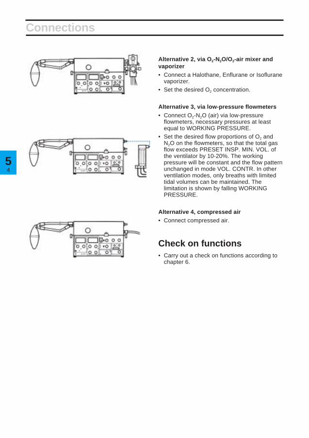
Alternative 2, via O2-N2O/O2-air mixer andvaporizer• Connect a Halothane, Enflurane or Isoflurane
vaporizer.• Set the desired O2 concentration.
Alternative 3, via low-pressure flowmeters• Connect O2-N2O (air) via low-pressure
flowmeters, necessary pressures at leastequal to WORKING PRESSURE.
• Set the desired flow proportions of O2 andN2O on the flowmeters, so that the total gasflow exceeds PRESET INSP. MIN. VOL. ofthe ventilator by 10-20%. The workingpressure will be constant and the flow patternunchanged in mode VOL. CONTR. In otherventilation modes, only breaths with limitedtidal volumes can be maintained. Thelimitation is shown by falling WORKINGPRESSURE.
Alternative 4, compressed air• Connect compressed air.
Check on functions• Carry out a check on functions according to
chapter 6.

1616
Chapter 6
Check onfunctionsA check on functions must always be carried outafter cleaning and before connecting a patient.
Accessories: Patient tubes, Y-piece, test lungand manual ventilation accessory. If anymalfunction is detected during the check, seechapter 8, Troubleshooting, or chapter 13,Calibration.
In this chapter:
1. Checks prior toconnection of powerand gas ....................... 6:2
2. Start-up....................... 6:23. Check for leakages .... 6:34. Check, manual
ventilation................... 6:35. Upper pressure limit
alarm ........................... 6:46. Minute volume ........... 6:47. Minute volume alarm . 6:48. O2 alarm ...................... 6:59. Apnea alarm ............... 6:5
10. Digital display ............ 6:611. Check on pressure
levels .......................... 6:612. Mains supply failure .. 6:613. Log sheet.................... 6:6

62
Prechecks
VOL. CONTR.
If preparation and prechecks, according tochapter 5, have been done, start from para. 3.
1. Checks prior toconnection of power and gas• Connect patient tubes, Y-piece, holder arm
and humidifier.• Make sure that the meters for AIRWAY
PRESSURE and EXPIRED MINUTEVOLUME give a zero reading.
• Set the mode selector at VOL. CONTR.• Set alarm limits to end positions, according
to the picture.• Set the scale range for ADULTS.• Set the TRIG SENSITIVITY to -20 cm H2O.• Set the UPPER PRESS. LIMIT to 80 cm H2O.• Set PEEP and INSP. PRESS. LEVEL to
0 cm H2O.
2. Start-up• Connect the ventilator to mains.• Set the mains switch on the rear of the
ventilator to on.• Make sure that the green lamp lights up
when you switch on.• Make sure that the meters for AIRWAY
PRESSURE and EXPIRED MINUTEVOLUME still give a zero reading.
• Make sure that GAS SUPPLY ALARMactivates.
• Make sure that SET MIN. VOL. ALARM andSET O2 ALARM flash.
POWER ON SET O2 ALARMSET MIN. VOL. ALARMGAS SUPPLY ALARM
ADULTS
36
5
21
7
9
4
6
8
3
10
0
O2 FLUSH
MAN
CPAP
MAN.
CPAP
MAN.
CPAP
MAN.
CPAP
MAN.
60
60 10 257.5
0
30
INSP.= EXP.=
900C
003S
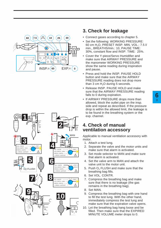
3. Check for leakage• Connect gases according to chapter 5.• Set the following: WORKING PRESSURE:
60 cm H2O, PRESET INSP. MIN. VOL.: 7.5 l/min., BREATHS/min.: 10, PAUSE TIME:30%, constant flow and INSP. TIME: 25%.
• Cover the Y-piece/Servo Humidifier andmake sure that AIRWAY PRESSURE andthe manometer WORKING PRESSUREshow the same reading during inspirationand pause.
• Press and hold the INSP. PAUSE HOLDbutton and make sure that the AIRWAYPRESSURE reading does not drop morethan 3 cm H2O during 5 seconds.
• Release INSP. PAUSE HOLD and makesure that the AIRWAY PRESSURE readingfalls to 0 during expiration.
• If AIRWAY PRESSURE drops more thanallowed, block the outlet pipe on the insp.side and repeat as described. If the pressuredrop is within the allowed limit, the leakage isto be found in the breathing system or theexp. channel.
4. Check of manualventilation accessoryApplicable to manual ventilation accessory withmotor.1. Attach a test lung.2. Separate the valve and the motor units and
make sure that alarm is activated.3. Set mode selector to MAN and make sure
that alarm is activated.4. Set the valve arm to MAN and attach the
valve unit to the motor unit.5. Push O2 FLUSH and make sure that the
breathing bag fills.6. Set VOL. CONTR.7. Compress the breathing bag and make
sure that there is no leakage (the gasremains in the breathing bag).
8. Set MAN.9. Compress the breathing bag with one hand
to fill the test lung. With the other hand,immediately compress the test lung andmake sure that the expiration valve opens.
10. Let the breathing bag hang loose and befilled. Then make sure that the EXPIREDMINUTE VOLUME meter drops to 0.
VOL. CONTR.
VOL.CONTR + SIGH
PRESS. CONTR.
PRESS. SUPPORT
VOL. CONTR.
VOL.CONTR + SIGH
PRESS. CONTR.
PRESS. SUPPORT
VOL. CONTR.
VOL.CONTR + SIGH
PRESS. CONTR.
PRESS. SUPPORT
VOL. CONTR.
VOL.CONTR + SIGH
PRESS. CONTR.
PRESS. SUPPORT
900C
004S

64
Alarms
5. Upper pressure limit alarm• Set the mode selector at VOL. CONTR.• Block the Y-piece/Servo Humidifier.• Turn the knob UPPER PRESS. LIMIT to
55 cm H2O.• Make sure that inspiration is terminated and
the alarm is activated.• Turn the knob back to 80 cm H2O.
6. Minute volume• Set the respiratory rate at 20 BREATHS/min.• Connect a test lung.• Set the parameter selector at EXP. MIN.
VOL. l/min.• Make sure that the digital display and the
meter EXPIRED MINUTE VOLUME read7.5 ± 0.5 l/min after a few minutes.
7. Minute volume alarmLower alarm limit• Turn the knob LOWER ALARM LIMIT to
7.5 l/min and make sure that the alarm isactivated at 7.5 ± 0.5 l/min.
• Turn the knob LOWER ALARM LIMIT to0 l/min.
If gas evacuation should be used:• Connect the gas evacuation accessory.• Set the LOWER ALARM LIMIT to the value
which is to be used during the treatment.• Remove the test lung (“disconnect”).• Make sure that the LOWER ALARM LIMIT is
activated.• Make sure that the EXPIRED MINUTE
VOLUME meter reading is at least 25%below the alarm limit setting.
• If the alarm is not activated:—Set PEEP to 1 cm H2O—Check the alarm and meter reading asdescribed above
or—Decrease the evacuation flow until thealarm is activated. Also check the meterreading as described above.
Upper alarm limit• Turn the knob UPPER ALARM LIMIT to
7.5 l/min and make sure that the alarm isactivated at 7.5 ± 0.5 l/min.
• Turn the knob UPPER ALARM LIMIT to40 l/min.
UPPER PRESS. LIMIT
MIN. VOL. ALARM
EXP. MIN.VOL. l/min
VOL. CONTR.

56
20-22%
60
O2 KONC. %900C
000S
O2 LARM900C
001S
AlarmasAlarms
8. O2 alarm
When checking the O2 alarm, the workingpressure must be 60 cm H2O since the O2
cell is calibrated at this pressure.If there is no O2 cell, no digital display is
given when O2 CONC. % is set on theparameter selector.
If the O2 cell is expended but stillmounted, it has to be disconnected. If not,the LOWER ALARM LIMIT will beactivated.
A deterioration in the linearity and/or arapid fall in the values of O2 concentration,despite adequate O2 supply, indicates thatthe O2 cell is exhausted.
• Set the parameter selector at O2 CONC. %.• Set the gas mixer at the lowest O2
concentration value (air) and make sure thatthe digital display shows 20-22%.
• Set the gas mixer so that 40% is read on thedigital display.
Lower alarm limit• Turn LOWER ALARM LIMIT clockwise and
make sure that alarm is activated when theknob setting corresponds to the digitaldisplay (±1 scale division).
• Turn LOWER ALARM LIMIT to 18%.
Upper alarm limit• Turn UPPER ALARM LIMIT counter-
clockwise and make sure that alarm isactivated when the knob setting correspondsto the digital display (±1 scale division).
• Turn UPPER ALARM LIMIT to 100%.
9. Apnea alarm• Set TRIG. SENSITIVITY at -10.• Set the mode selector at PRESS.
SUPPORT.• Make sure that the APNEA ALARM is
activated approx. 15 s after the modechange.APNEA ALARM PRESS. SUPPORT
O2 ALARM
O2 CONC. %

66
Pressures
BREATHS/min
VOL. CONTR.
PRESS. CONTR.
EXP.
10. Digital display• Set the parameter selector at BREATHS/min.• Make sure that the value set with the
BREATHS/min knob corresponds to theBREATHS/min value read on the digitaldisplay.
11. Check on pressure levels• Set the mode selector at PRESS. CONTR.• Set BREATHS/min. to lowest value.• Set PEEP at +10 cm H2O.• Set INSP. PRESS. LEVEL at +10 cm H2O.• Make sure that the reading on the AIRWAY
PRESSURE meter remains at+20 ± 2 cm H2O during inspiration.
• Make sure that a PEEP level of10 ± 2 cm H2O is maintained on the AIRWAYPRESSURE meter at the end of expiration.
• Set PEEP and INSP. PRESS. LEVEL at0 cm H2O.
• Set the mode selector at VOL. CONTR.
12. Mains supply failurealarm• Switch off the ventilator with the mains switch
on the rear.• Make sure that the green lamp POWER ON
goes out and the audible alarm sounds.
13. Log sheet• Note on the log sheet that a check on
functions has been carried out.If any malfunctions are detected during thecheck, see chapter 8, Troubleshooting, orchapter 13, Calibration.

1717
Chapter 7
Connection topatientBe careful when moving the ventilator from thepreparation room to the operating theatre. If youbump into something, it may be necessary tocheck the functions before connection topatient.
For detailed description of the functions, seechapter 2.
Always start with ventilator checkedaccording to chapter 6.
In this chapter:
Compressible volume anddead space ........................7:2Controlled ventilation
VOL. CONTR. orVOL. CONTR. + SIGH ..............7:4PRESS. CONTR. ......................7:5
Supported ventilationPRESS. SUPPORT ...................7:6SIMV ..........................................7:7SIMV + PRESS. SUPPORT ......7:8
Spontaneous ventilationCPAP.........................................7:9
Manual ventilationMAN ....................................... 7:10

72
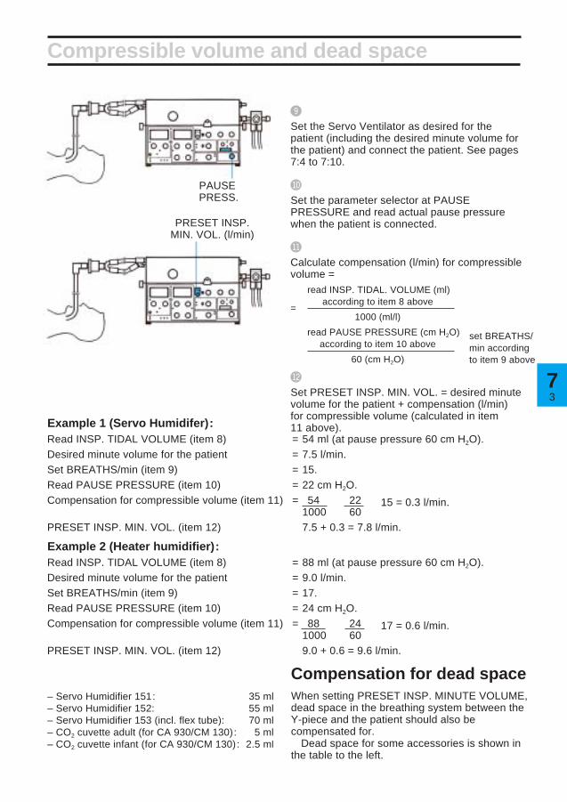
Compressible volume and dead space
VOL. CONTR.
Compensation forcompressible volumeSome of the preset minute volume does notreach the patient because it is needed forcompression of gas in tubes and humidifier.The compressible volume of the ServoVentilator itself is negligible.
When setting the preset insp. minute volume,the compressible volume must be compensatedfor by adding a corresponding minute volume tothe minute volume for the patient.
Compensation procedure
!
Connect the complete breathing system withpatient tubes and Servo Humidifier or heaterhumidifier to the Servo Ventilator.
@
Set WORKING PRESSURE at 60 cm H2O.
#
Set the front panel values as shown. (Valuesmarked in green).
$
Set PRESET INSP. MIN. VOL. at 10 l/min.
%
Set UPPER PRESS. LIMIT for AIRWAYPRESSURE at 80 cm H2O.
^
Set the parameter selector at INSP. TIDALVOLUME.
&
Block the opening of the Y-piece/ServoHumidifier.
*
Note the reading on the INSP. TIDAL VOLUME(ml) display.
INSP. TIDAL VOL.
37
Compressible volume and dead space
(
Set the Servo Ventilator as desired for thepatient (including the desired minute volume forthe patient) and connect the patient. See pages7:4 to 7:10.
BL
Set the parameter selector at PAUSEPRESSURE and read actual pause pressurewhen the patient is connected.
BM
Calculate compensation (l/min) for compressiblevolume =
read INSP. TIDAL. VOLUME (ml)
=according to item 8 above
×1000 (ml/l)
read PAUSE PRESSURE (cm H2O)according to item 10 above
×60 (cm H2O)
BN
Set PRESET INSP. MIN. VOL. = desired minutevolume for the patient + compensation (l/min)for compressible volume (calculated in item11 above).
Compensation for dead spaceWhen setting PRESET INSP. MINUTE VOLUME,dead space in the breathing system between theY-piece and the patient should also becompensated for.
Dead space for some accessories is shown inthe table to the left.
– Servo Humidifier 151: 35 ml– Servo Humidifier 152: 55 ml– Servo Humidifier 153 (incl. flex tube): 70 ml– CO2 cuvette adult (for CA 930/CM 130): 5 ml– CO2 cuvette infant (for CA 930/CM 130): 2.5 ml
PAUSEPRESS.
Example 1 (Servo Humidifer):Read INSP. TIDAL VOLUME (item 8) = 54 ml (at pause pressure 60 cm H2O).Desired minute volume for the patient = 7.5 l/min.Set BREATHS/min (item 9) = 15.Read PAUSE PRESSURE (item 10) = 22 cm H2O.Compensation for compressible volume (item 11) = 54 × 22 × 15 = 0.3 l/min.
1000 60PRESET INSP. MIN. VOL. (item 12) 7.5 + 0.3 = 7.8 l/min.
Example 2 (Heater humidifier):Read INSP. TIDAL VOLUME (item 8) = 88 ml (at pause pressure 60 cm H2O).Desired minute volume for the patient = 9.0 l/min.Set BREATHS/min (item 9) = 17.Read PAUSE PRESSURE (item 10) = 24 cm H2O.Compensation for compressible volume (item 11) = 88 × 24 × 17 = 0.6 l/min.
1000 60PRESET INSP. MIN. VOL. (item 12) 9.0 + 0.6 = 9.6 l/min.
set BREATHS/min accordingto item 9 above
PRESET INSP.MIN. VOL. (l/min)

74
Controlled ventilation
To protect the patient against high pressures,always start from a low value.
VOL. CONTR. or VOL. CONTR. + SIGH
Connect the patient
!Set the WORKING PRESSURE.
@Set the mode selector at VOL. CONTR. or VOL. CONTR. +SIGH.
#Set the desired minute volume (e.g. by means of a Radfordnomogram).
$Select the curve shape for the inspiration flow.
%Set the respiratory rate, BREATHS/min.
^Set the INSP. TIME %.
&Set the PAUSE TIME %.
*Set the mixer.
(Set the LOWER ALARM LIMIT and UPPER ALARM LIMITfor O2 CONC. %.
BLSet the parameter selector.
BMSet the PEEP-level.
BNSet the UPPER PRESS. LIMIT for AIRWAY PRESSURE toapproximately 10 cm H2O above the patient’s airway pressure.
BOSet the TRIG. SENSITIVITY.
BPSet the scale INFANTS/ADULTS.
BQConnect the ventilator to the patient and check:– that the patient’s chest rises and falls in time with the presetrespiratory rate.– the tidal volumes on the digital display and the reading on theEXPIRED MINUTE VOLUME meter.– that the AIRWAY PRESSURE meter gives a reading duringinspiration, and that the reading falls to 0 cm H2O or,alternatively, to PEEP-level during expiration.
BRSet the LOWER ALARM LIMIT and UPPER ALARM LIMIT forEXPIRED MINUTE VOLUME. If the VOL. CONTR. + SIGHmode is selected, it may be necessary to increase the UPPERALARM LIMIT for EXPIRED MINUTE VOLUME as well as theUPPER PRESS. LIMIT for AIRWAY PRESSURE. This is donein order to avoid activating the alarms when the sigh occurs.
In VOL. CONTR. or VOL. CONTR. + SIGH modewith respiratory rate above 80 BREATHS/min,INSP. TIME % should be set at 33 or 50%.Otherwise the ventilator may give incorrectminute volumes and incorrect EXPIREDMINUTE VOLUME meter readings.

57
Controlled ventilation
PRESS. CONTR.
!Set the WORKING PRESSURE.
@
Set the mode selector at PRESS. CONTR.
#
Set the respiratory rate, BREATHS/min.
$
Set the INSP. TIME %.
%
Set the PAUSE TIME %.
^
Set the mixer.
&
Set the LOWER ALARM LIMIT and UPPERALARM LIMIT for O2 CONC. %.
*
Set the parameter selector.
(
Set the INSP. PRESS. LEVEL.
BL
Set the PEEP-level.
BM
Set the UPPER PRESS. LIMIT for AIRWAYPRESSURE.
BN
Set the TRIG. SENSITIVITY.
BO
Set the scale INFANTS/ADULTS.
BP
Connect the patient and adjust the INSP.PRESS. LEVEL so that the patient receivesdecided tidal volumes and check:– the reading on the EXPIRED MINUTEVOLUME meter.– that the AIRWAY PRESSURE meter gives areading during inspiration, and that the readingfalls to 0 cm H2O, or alternatively, to PEEP-level, during expiration.
BQ
Set the LOWER ALARM LIMIT and UPPERALARM LIMIT for EXPIRED MINUTE VOLUME.
Connect the patient.To protect the patient against high pressures,always start from a low value.

76
Supported ventilation
!
Set the WORKING PRESSURE.
@
Set the mode selector at PRESS. SUPPORT.
#
Set the respiratory rate, BREATHS/min.(determines the length of inspiration time).
$
Set the mixer.
%
Set the LOWER ALARM LIMIT and UPPERALARM LIMIT for O2 CONC. %.
^
Set the parameter selector.
&
Set the INSP. PRESS. LEVEL.
*
Set the PEEP-level.
PRESS. SUPPORT
To protect the patient against high pressures,always start from a low value.Connect the patient
(
Set the UPPER PRESS. LIMIT for AIRWAYPRESSURE.
BL
Set the TRIG. SENSITIVITY.
BM
Set the scale INFANTS/ADULTS.
BN
Connect the patient and check that he cantrigger the ventilator. Adjust the INSP. PRESS.LEVEL so that the patient receives decidedtidal volumes and check:–the reading on the EXPIRED MINUTEVOLUME meter.– that the AIRWAY PRESSURE meter gives areading during inspiration, and that the readingfalls to 0 cm H2O or, alternatively, to PEEP-level during expiration.
BO
Set the LOWER ALARM LIMIT and UPPERALARM LIMIT for EXPIRED MINUTE VOLUME.

77
Supported ventilation
SIMV
Connect the patient.To protect the patient against highpressures, always start from a low value.
!
Set the WORKING PRESSURE.
@
Set the mode selector at SIMV.
#
Set the rate, LOW RATE/HIGH RATE.
$
Set the SIMV BREATHS/min.
%
Set the PRESET INSP. MIN. VOL. l/min.
^
Set the respiratory rate, BREATHS/min.
&
Set the INSP. TIME %.
*
Set the PAUSE TIME %.
(
Set the mixer.
BL
Set the LOWER ALARM LIMIT and UPPERALARM LIMIT for O2 CONC. %.
BM
Set the parameter selector.
BN
Set the PEEP-level.
BO
Set the UPPER PRESS. LIMIT for AIRWAYPRESSURE.
BP
Set the TRIG. SENSITIVITY.
BQ
Set the scale INFANTS/ADULTS.
BR
Connect the patient and check:– that the patient can trigger the ventilator.– the tidal volumes on the digital display andthe reading on the EXPIRED MINUTEVOLUME meter.– that the AIRWAY PRESSURE meter gives areading during inspiration, and that the readingfalls to 0 cm H2O or, alternatively, to PEEP-level, during expiration.
BS
Set the LOWER ALARM LIMIT and UPPERALARM LIMIT for EXPIRED MINUTE VOLUME.

78
Supported ventilation
SIMV + PRESS. SUPPORT
Connect the patient.
To protect the patient against high pressures,always start from a low value.
BN
Set the INSP. PRESS. LEVEL.
BO
Set the PEEP-level.
BP
Set the UPPER PRESS. LIMIT for AIRWAYPRESSURE.
BQ
Set the TRIG. SENSITIVITY.
BR
Set the scale INFANTS/ADULTS.
BS
Connect the patient and check that he can trigger theventilator. Adjust the INSP. PRESS. LEVEL so thatthe patient receives the decided tidal volumes andcheck:– the reading on the EXPIRED MINUTE VOLUMEmeter.– that the AIRWAY PRESSURE meter gives areading during inspiration, and that the reading fallsto 0 cm H2O or, alternatively, to PEEP-level duringexpiration.
BT
Set the LOWER ALARM LIMIT and UPPER ALARMLIMIT for EXPIRED MINUTE VOLUME.
!
Set the WORKING PRESSURE.
@
Set the mode selector at SIMV + PRESS. SUPPORT.
#
Set the rate, LOW RATE/HIGH RATE.
$
Set the SIMV BREATHS/min.
%
Set the PRESET INSP. MIN. VOL. l/min.
^
Set the respiratory rate, BREATHS/min.
&
Set the INSP. TIME %.
*
Set the PAUSE TIME %.
(
Set the mixer.
BL
Set the LOWER ALARM LIMIT and UPPER ALARMLIMIT for O2 CONC. %.
BM
Set the parameter selector.

97
Spontaneous ventilation
CPAP
Connect the patient. To protect the patient against highpressures, always start from a low value.
*
Set the TRIG. SENSITIVITY.
(
Set the scale INFANTS/ADULTS.
BL
Connect the patient and check:– that he can trigger the ventilator.– the tidal volumes on the digital display andthe reading on the EXPIRED MINUTEVOLUME meter.– that the AIRWAY PRESSURE meter gives areading during inspiration, and that the readingfalls to 0 cm H2O or, alternatively, to PEEP-level during expiration.
BM
Set the LOWER ALARM LIMIT and UPPERALARM LIMIT for EXPIRED MINUTE VOLUME.
!
Set the WORKING PRESSURE.
@
Set the mode selector at CPAP.
#
Set the mixer.
$
Set the LOWER ALARM LIMIT and UPPERALARM LIMIT for O2 CONC. %.
%
Set the parameter selector.
^
Set the PEEP-level.
&
Set the UPPER PRESS. LIMIT for AIRWAYPRESSURE.

710
*
Manual ventilation
Connect the patient.
Set the values to be used after completedmanual ventilation.
!
Set the WORKING PRESSURE.
@
Set the mode selector at MAN.
#
Set the mixer.
$
Set the LOWER ALARM LIMIT and UPPERALARM LIMIT for O2 CONC. %.
%
Set the parameter selector.
^
Make sure that the manual ventilation valve isin position MAN.
&
Set the PRESET INSP. MIN. VOL. l/min. (Setthe value so that the breathing bag becomessatisfactorily filled).
*
Set the UPPER PRESS. LIMIT for AIRWAYPRESSURE.
(
Set the PEEP-level.
Always set UPPER PRESS. LIMIT duringmanual ventilation.
In the case of a power failure, manualventilation is not possible with ServoVentilator 900 C.
The Manual Ventilation Accessory 963must not be connected to Servo Ventilator900 C.
BL
Set the scale INFANTS/ADULTS.
BM
Connect the patient and check:– that the patient’s chest rises and falls whenmanual ventilation is performed.– the tidal volumes on the digital display andthe reading on the EXPIRED MINUTEVOLUME meter.– that the AIRWAY PRESSURE meter gives areading during inspiration, and that the readingfalls to 0 cm H2O or, alternatively, to PEEP-level during expiration.
BN
Set the LOWER ALARM LIMIT and UPPERALARM LIMIT for EXPIRED MINUTE VOLUME.
To protect the patient against highpressures, always start from a lowvalue.
Manual ventilation valve in position MAN.

1818
Chapter 8
Clinical judgementand TroubleshootingClinical judgement when an alarm indicates thatpreset ventilation can no longer be maintained.If possible, try to first eliminate technical faultsby carrying out a check on functions.
In this chapter:
Clinical judgement ........... 8:2Technical troubleshooting 8:6

82
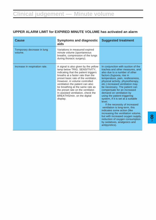
LOWER ALARM LIMIT for EXPIRED MINUTE VOLUME has activated an alarm
Cause Symptoms and diagnostic Suggested treatmentaids
Leakage between the An air leakage may be detected Correct cuff pressure. If thetracheal wall and tracheostomy by palpation or auscultation over leakage cannot be sealed, increasetube or cannula. the trachea. the PRESET INSP. MIN. VOL. so
that expired minute volume settlesat a suitable level. Leakagesmainly occur during the inspirationphase and the pause at the end ofinspiration when the pressure inthe trachea is high.Prolonged inspiration time.
Temporary increase of lung Variations in measured expiredvolume. minute voume (spontaneous
breaths or sigh).
Ventilation obstruction, resulting UPPER PRESS. LIMIT for See UPPER PRESS. LIMIT for
in a pressure activated AIRWAY PRESSURE has also AIRWAY PRESSURE.interruption of inspiration. activated an alarm.
Insufficient patient respiration Variations in the measuredduring SIMV, CPAP, PRESS. expired minute volume.SUPPORT.
Clinical judgement — Minute volume
Revert to normal ventilation, orSIMV-position which gives anincreased, controlled ventilation.
In SIMV, increase the SIMVBREATHS/min. or the preset tidalvolume.
In PRESS. SUPPORT, increasethe INSP. PRESS.LEVEL if thetidal volume is too small but thepatient has adequate respiratoryrate.
38
Clinical judgement — Minute volume
UPPER ALARM LIMIT for EXPIRED MINUTE VOLUME has activated an alarm
Cause Symptoms and diagnostic Suggested treatmentaids
Temporary decrease in lung Variations in measured expiredvolume. minute volume (spontaneous
breaths, compression of the lungsduring thoracic surgery).
Increase in respiration rate. A signal is also given by the yellow In conjunction with suction of thelamp below TRIG. SENSITIVITY, trachea and other measures, andindicating that the patient triggers also due to a number of otherbreaths at a faster rate than the factors (hypoxia, rise inpreset basic rate of the ventilator. temperature, pain, restlessness,However, in volume controlled physical activity, physiotherapy,ventilation the patient can also etc.) increased ventilation maybe breathing at the same rate as be necessary. The patient canthe preset rate on the ventilator. compensate for an increasedIn assisted ventilation, check the demand on ventilation byBREATHS/min. on the digital using the patient-triggeringdisplay. system, if it is set at a suitable
level.If the necessity of increased
ventilation is long-term, thisindicates some action (likeincreasing the ventilation volume,but with increased oxygen supply,reduction of oxygen consumptionby sedatives, analgesics andantipyretics).

84
Clinical judgement — Pressures
UPPER PRESSURE LIMIT for AIRWAY PRESSURE has activated an alarm
(Combined with an interruption of inspiration, in which case LOWER ALARM for EXPIREDMINUTE VOLUME may also have been activated.)
Cause Symptoms and diagnostic Suggested treatmentaids
Airways obstructions In cases of substantialobstructions, recordings of flowand airway pressure indicateincreased airway resistance. Increased elastic resistance (low compliance) may also occur at the same time. When theUPPER PRESS. LIMIT for AIRWAYPRESSURE is repeatedlyexceeded and, at the same time,accompanied by interruptions ofinspiration, the expired minutevolume falls, and an alarm isactivated.
a) Accumulation of mucus in Auscultatory rales, Rhoncal Suction, Expectorants,airways. fremitus on parts of the chest. Physiotherapy.
b) Bronchospasm. Bronchit. Whistling or wheezing respiratory Bronchodilator drugs, etc.sounds during auscultation.
c) Tracheostomy tube or cannula Often occurs suddenly and with Removal of kinks or correction ofhas slipped out of the trachea, or variations. Difficult to insert a position. Possibly a reduction ofhas been kinked or twisted, so suction catheter. Resistance is pressure in the cuff, and possiblythat the opening is blocked. The felt when ventilating manually a replacement of tracheostomycuff protrudes over the opening with a breathing bag. tube or cannula. In case of anof the tube or cannula. Coagulate absolute blockage, it may beor dried mucus block the airway. necessary to withdraw the
cannula or tube. The blockagecan often be located in the orificeof the tube.

58
Clinical judgement — Pressures
Cause Symptoms and diagnostic Suggested treatmentaids
Reduced elasticity of the Recordings of flow and pressurerespiratory organs. indicate a high elastic resistance
(low compliance).
a) Increased muscular tonus Sometimes caused by mucus, Temporary increase of minutein the patient. Coughing. often after suction. The patient volume and BREATHS/min.
works against the ventilator. Often more convenient for thepatient if the inspiratory flow isincreased by reducing INSP.TIME %, until negative airwaypressure caused by spontaneousbreathing ceases. Consideradministering analgesics andsedatives. Blood gas tests.Adjustment of ventilator settingsand alarm limits.
b) Atelectasis, pneumonia, Reduced respiratory sounds over Check of blood gases. PEEP,pulmonary edema. affected sections of the lungs. physiotherapeutic treatment,
Possible rales during auscultation. change of patient’s position,Roentgenologic changes. Often postural drainage, sigh function.accompanied by hypoxia.
c) Blockage of main bronchus. The cause is often that the Adjustment of tube position.tracheal or the tracheostomy tubehas slipped too far down.
Reduced respiratory sounds.Roentgenologic changes.Irregular movements of thethorax. Hypoxia, increasedresistance and reducedcompliance.
d) Pneumothorax. Often occurs suddenly. Out-suction of air in pleura.Reduced respiratory sounds,
and increased percussive toneover the affected side. Sometimesfollowed by subcutaneousemphysema. Roentgenologicchanges.
Cause Symptoms and diagnostic Suggested treatmentaids
Patient triggers spontaneousbreaths.
The airway pressure (SIMV notused) is usually negative (orunder preset PEEP-level) only atthe start of inspiration. Negativepressure (or pressure underpreset PEEP-level) during thewhole inspiration indicates aconsiderable deviation betweenpreset minute volume and theminute volume the patient needs.
SIMV treatment normally. Patienttriggering is more oftenacceptable and suitable. Usuallythe patient requires a larger gasvolume than that supplied by thecontrolled breaths. In cases ofunexpected patient triggering, anincrease of preset minute volumeshould be considered.
TRIG. SENSITIVITY lamp flashes

86
Technical trouble — Power
Malfunction Possible cause Action
Power cable not connected. Connect power cable.
Blown fuse in ventilator. Replace fuse.
On-Off switch in the Off- Switch to On.position.
Ventilator does not start
Malfunction Possible cause Action
Green lamp goes out, ventilator No mains supply. Ventilate patient manually.stops, audible alarm.
Manual ventilation accessory on Servo Ventilator 900 C cannot be used during a power failure.
Green lamp goes out at intervals Loose connection. Insert the power cable in wall+ simultaneous stop of ventilator. socket or ventilator socket
properly.
Ventilator stops during operation

78
Malfunction Possible cause Action
Working pressure varies. Pressure/flow from gas source not Low-pressure connection:enough. increase gas volume/pressure.Fault in gas supply. High-pressure connection:
check gas source/mixer.
Large tidal volumes and short Change respiratory pattern or gasinspiration times set on ventilator. volume.Incorrectly adjusted inlet valve in To be dealt with by servicegas supply unit. technician.
WORKING PRESSURE reading Tube connection is loose between Connect tube connections.is 0, but GAS SUPPLY ALARM the safety valve and thenot activated. manometer for WORKING
PRESSURE.
WORKING PRESSURE reading Working pressure not set. Set working pressure.is 0. GAS SUPPLY ALARM is Insufficient gas supply. Check gas connections/gasactivated. (Alarm is also activated Deformed valve arm on gas mixers/flowmeters.for the LOWER ALARM LIMIT for supply unit. To be dealt with by serviceEXPIRED MINUTE VOLUME). technician.
Malfunction Possible cause Action
Accumulation of secretion. Suction of trachea
Kink in tracheal tube. Remove the kink or replace thetube.
Patient tries to breathe, increased Clinical judgement.muscle-tonus.
The tracheal tube has slipped Correct the tube position.down into a bronchus.
Spasms in respiratory airways. Medicaments.
Change in patient’s positioning Possible change of respiratorye.g. on operation table. pattern.
Pneumothorax. Suction drainage.
Sigh. Set the UPPER PRESS. LIMITalarm somewhat higher.
Malfunction Possible cause Action
AIRWAY PRESSURE reading Loose tube between inspiration Attach the tube.is 0. channel and pressure transducer.
Technical trouble — Pressures
UPPER PRESS. LIMIT ALARM for AIRWAY PRESSURE has been activated
No airway pressure
Fault in working pressure

88
Malfunction Possible cause Action
Connection between patient and Reconnect the connections, e.g.ventilator has loosened. Y-piece, trach. tube, patient tube,
water trap.
Leakage in trach. tube/cannula Adjust the cuff, or change trachcuff. tube/cannula cuff.
Changes in upper airway Same action as for UPPERpressure so that the expiration PRESS. LIMIT alarm for airwayvalve opens at attained upper pressure.pressure limit.
Technical trouble — Minute volume
LOWER ALARM LIMIT for EXPIRED MINUTE VOLUME has been activated
Insufficient patient respiration,during SIMV, SIMV + PRESS.SUPPORT, PRESS. SUPPORTor CPAP.
Change SIMV-rate, INSP.PRESS. LEVEL, or change tocontrolled ventilation.
Increase working pressure, orchange respiratory pattern.
At low pressure: increase gasflow. At high pressure: check gassource/mixer.
Assemble correctly.
Working pressure too low (lowerthan the airway pressure neededto provide preset ventilation).
Insufficient gas supply, e.g. fromflowmeters.
Leakage due to poor assemblingof parts of inspiration channel orexpiration channel.
Leakage in ventilator Safety valve out of position. Put the valve in position.
Connection to one of the pressure Reconnect.transducers has loosened.
Rubber valve defect on insp./exp. Replace rubber valve.side.

98
Technical trouble — Minute volume
UPPER ALARM LIMIT for EXPIRED MINUTE VOLUME has been activated
Malfunction Possible cause Action
Deeper breaths in VOL. CONTR. + Set the UPPER ALARM LIMITSIGH, increase in expired minute somewhat higher.volume (every hundredth breath).
Patient breathes more than Clinical judgement.expected during SIMV, SIMV +PRESS. SUPPORT, CPAP,PRESS. SUPPORT.
Condensation in exp. flow Empty water trap if necessary.transducer. Protect exp. inlet by an angled
humidity trap or a bacteria filter.Dry run the ventilator with a testlung if these actions are notenough.
Particles of medicines in exp. flow Replace exp. flow transducer (ortransducer. try to clean the transducer
according to chapter 10).
Flow transducer is defective. Replace exp. flow transducer.

810
Technical trouble—Others
Leakage detected in ventilator during check on functions
Malfunction Possible cause Action
Connection between safety valve Reconnect.and manometer has loosened.
Leakage at inlet valve of gas Replace gas supply unit.supply unit.
Leakage in non-return valve of Replace gas supply unit.gas supply unit.
Leakage in bellows. Replace bellows (see chapter 11).
Overfilling of bellows, safety valve Valve arm to be adjusted byopens (caused by deformed valve service technician.arm on gas supply unit).
Leakage in bacteria filter. Replace gas supply unit.
Bad connections in the inspiratory Connect properly.or expiratory channel.
Incorrect values/readings during check on functions
Malfunction Possible cause ActionVentilator not calibrated. Calibrate ventilator (see chapter
13).
Malfunction Possible cause ActionRattle from step motor. Must be dealt with by service
technician as soon as possible.
“Singing” noise from springs Springs hook into one another. Dealt with by service technician,under the bellows. Not dangerous and does not when convenient.
interfere with function of ventilator.
Malfunction Possible cause ActionLeakage in the expiratory channelwhich causes spontaneoustriggering (when PEEP is used inthe presence of leakages).
Noises
O2 cell
Trig sensitivity flashes without activity from the patient
Malfunction Possible cause ActionNo digital display when O2 O2 cell not inserted. Insert an O2 cell (see chapter 12).
CONC. % is selected.
Rapidly falling O2 CONC. % a) Insufficient O2 supply. a) Regulate O2 supply.values. LOWER ALARM LIMIT b) O2 cell exhausted. b) Replace O2 cell (see chapter 12)activates an alarm. c) O2 cell not properly inserted. c) Insert properly.
UPPER ALARM LIMIT activates Insufficient air/N2O supply. Regulate gas supply.an alarm.

1919
Chapter 9
RecordingThe ventilator can be connected to a recorder,e.g. a Siemens-Elema Mingograf.
In this chapter:
Connection..................... 9:2Calibration...................... 9:3Curves ............................ 9:4

92
Connection
Recorder output
• Connect the recorder cable to the 37-pinsocket at the rear of the ventilator. The cablehas two connections to the MingografRecorder, i.e. one for recording of pressurecurves and one for recording of flow curves.
• The output signals from the recorder cableare adapted to the inputs of Siemens-Elema’s Mingograf Recorders.
Use only the recorder cable intended forServo Ventilator 900 C.
Never connect or disconnect auxiliaryequipment while the ventilator is connectedto a patient.

39
a) Flow
!
Adjust the 0-line on the recorder.
@
Set WORKING PRESSURE to 60 cm H2O.
#
Set the UPPER PRESS. LIMIT higher than theWORKING PRESSURE.
$
Select constant flow.
%
Set the respiratory rate to 10 BREATHS/min.
^
Set the mode selector at VOL. CONTR.
&
Calculate inspiratory flow as follows:Insp. flow (l/s) =
PRESET INSP. MIN. VOL. (l/min)60
×100
INSP. TIME (%)
*
A suitable calibration level for normal conditionsis to allow 0.5 l/s correspond to 1 cm deflectionon the recorder paper. 0.5 l/s corresponds to asetting of 7.5 l/min for PRESET INSP. MIN.VOL. and 25% INSP. TIME.
(
After this, adjust the recorder to desiredreading.b) Pressure
!
Adjust the 0-line on the recorder.
@
Block the inspiration outlet during the inspirationphase, or connect the inspiration outlet to theexpiration inlet with a patient tube.
#
A suitable calibration level for normal conditionsis to allow 20 cm H2O correspond to 1 cmdeflection on the recorder paper. The presetWORKING PRESSURE should then,temporarily, be set to 20 cm H2O.
$
Adjust the recorder to desired reading.
Calibration
VOL. CONTR.
×

94
Pressure and flow curvesIf the flow curve is square-shaped and aninspiratory pause is used, it will be possible tocalculate, from the pressure curve, airwayresistance and the elasticity of the lungs and ribcage, i.e. compliance. It is possible tocontinuously follow changes in these values inpatients with obstructive lung diseases and alsowhen ventilating patients for prolonged periods.
For all measurements, it is assumed that thepatient makes no breathing attempts.
It is possible to read the effects from thechanges in the ventilation, e.g. optimal PEEP orbroncho-dilating agents, which give a directchange in resistance.
Assessment of curvesVolume controlled ventilation and constantflow, in order to calculate resistanceResistance is indicated by a pressure drop thatoccurs during the pause.• Big amplitude of pressure drop indicates high
airway resistance.Resistance is calculated according to theformula:Resistance (cm H2O/l/s) =
= Pres.(cm H2O) ×60
PRESET INSP. MIN. VOL.(l/min)
× Insp. %100
Volume controlled or pressure controlledventilation, in order to calculate complianceCompliance is indicated by a pressure dropduring the expiration phase.• Big drop in pressure (P compl) indicates low
compliance, i.e. poor elasticity in lungs andchest, i.e. high elastic resistance.
Compliance is calculated according to thefollowing formula:Compliance (ml/cm H2O) =
= PRESET INSP. MIN. VOL. (l/min)BREATHS/min
× 1000
Pcompl. (cm H2O)
Not valid if the flow has not reached zero whenthe next expiration starts or if the patient makesbreathing efforts.
Curves
Constant Accelerating Deceleratingflow flow flow
Insp. Pause Exp.
Flo
wA
irway
pre
ssur
eF
low
Airw
ay p
ress
ure
×

110
110
Chapter 10
Routine cleaningServo Ventilator 900 C has been constructed sothat the cleaning and sterilizing of contaminatedparts can be carried out simply and rapidly.
Routine cleaning should be carried out afterevery patient or daily, according to the hospitalroutines.
In this chapter:
Hygiene .......................... 10:2Dismantling .................... 10:2Cleaning ......................... 10:4Assembling .................... 10:6

102
Hygiene
The gas, which passes the ventilator’sinspiration system and is supplied to the patientis usually clean and dry. It also passes abacteria filter.
The dry environment gives unfavorableconditions for bacterial growth, and bacteriaspreading against the gas flow is consideredvirtually impossible.
Bacteria from the patient will, on the otherhand, appear in the moist environment of theexpiration side. By attaching a disposablebacteria filter to the expiratory inlet of theventilator, the transmission of bacteria to theexpiratory channel and out into the room isreduced. This reduces the risks of infectionsbeing spread to the staff as well as crossinfections between patients.
Exchange or cleaning of patient tubes andthe parts of the expiratory channel andexchange of expiratory bacteria filter isrecommended after each patient or accordingto the hospital routines. The bacteria filtershould be replaced according to manufacturerrecommendations.
The gas conveying parts of the expirationsystem can be decontaminated and sterilized.
The parts of the inspiration system should besterilized or replaced by clean parts after anoperating time of 1000 hours or, at the latest,half-yearly, according to chapters 10 and 11 inthis manual.
All personnel should be aware of the risk ofparts being infected when disassembling andcleaning the ventilator.
Dismantling
!
• Remove gas connections.• Disconnect the power cable.• Remove patient tubes, humidifier and manual
ventilation accessory.• Remove the O2FLUSH quick-coupling
(if used).• Wipe the outside of the ventilator with a cloth
moistened in a disinfectant.
@
• Open the lid on the pneumatic unit.• Disconnect the connector from the flow
transducer on the expiration side.• Remove the bacteria filter from the pressure
transducer marked EXP.

310
Dismantling
#
• Lift the whole expiration channel upwards.
• Dismantle the different parts.• Discard the tube and bacteria filter for the
pressure transducer.

104
Cleaning
!
• Let the flow transducer lie in a 70% ethylalcohol solution for about one hour.
• If solutions other than ethyl alcohol are used,rinse the solution from the flow transducer bycarefully moving the transducer to and fro ina bowl containing distilled water.
Let the water run off the flow transducer afterrinsing.
• Make sure that the fine mesh net in thetransducer is not blocked or damaged, andthat the disc in the small channel is inposition.
The flow transducer is a precisioninstrument and must be handled carefully.The metal disc in the small channel of thetransducer is very fragile and may break if itis handled carelessly.
Do not poke at the metal disc in the smalltransducer channel.
Do not flush the channel with water.The flow transducer must not be cleaned
in a dish washing machine, by ultrasound orby using agents which contain aldehydes.
Solutions other than ethyl alcohol maygive rise to disturbances in the function ofthe flow transducer.
If agents other than ethyl alcohol are usedfor disinfection, the cleaning routines shouldbe carried out according to the instructionsof the respective manufacturers.
The agents used for cleaning anddisinfection must have a pH between 4 and8.5.
1 hour
Ethyl alcohol
Water

510
MAN AUT
Cleaning
@
• If the manual ventilation valve should becleaned, do as follows:
• Set the valve in the MAN position, and let itlie in a 70% ethyl alcohol solution for aboutone hour.
#
• Let the other parts (NOTE! not the flowtransducer and manual ventilation valve) liein a disinfectant for about one hour.
• After this, rinse the parts in water to removethe disinfectant.
$
• Autoclave all parts, including the flowtransducer and manual ventilation valve at amaximum temperature of 150˚C (300˚F).
Manual ventilationvalve in position
MAN
1 hour
Disinfectant

106
Assembling
!
• Put a new bacteria filter with tube on thepressure transducer marked EXP.
VOL. CONTR.
Make sure that the bacteria filter (withoutcaps) is properly connected to the pressuretransducer. Otherwise, the expiration couldbe blocked.
@
• Assemble the expiration channel.• Connect the tube from the pressure
transducer on the expiration side to the metalpipe. Make sure that the pressure transducertube is not bent or pinched. The tube shouldbe placed below the silicone rubber muff.
• Push the expiration channel down intoposition.
• Make sure that the expiration valve is notbent or twisted.
#
• Connect the connector to the flow transducer.• Make sure that the serial numbers on the
transducer and on the connector agree.
$
• Fit the manual ventilation accessory,O2FLUSH quick-coupling (if required) andnew patient tubes.
%
• Note on the log sheet that routine cleaninghas been carried out.
^
• Carry out a check on functions after cleaning(see chapter 6).After autoclaving in certain autoclaves, theflow transducer may be somewhat damp, andthis may give rise to incorrect readings on theEXPIRED MINUTE VOLUME meter.
The moisture is removed in the following way:• Connect the power cable.• Connect a test lung to the Y-piece.• Connect compressed air to the ventilator and
let it run for about 15 minutes with a PRESETINSP. MIN. VOLUME of 7.5 l/min.
• Store the ventilator under a cover in normalroom temperature and humidity.

111
111
Chapter 11
1000 hoursoverhaul withcomplete cleaningAfter every 1000 hours of operation or afterevery six months, at the latest, a 1000 hoursoverhaul should be carried out.
In this chapter:
Dismantling .................... 11:2Cleaning ......................... 11:4Assembling .................... 11:6

112
Dismantling
!
• Remove the gas connections.• Disconnect the power cable.• Remove the patient tubes, humidifier and
manual ventilation accessory. Alsodisconnect the O2FLUSH quick-coupling(if used).
• Wipe the outside of the ventilator with a clothmoistened in a disinfectant.
@
• Open the lid on the pneumatic unit.
#
• Open the lid over the bellows by releasing thelocking pawls on the front edge of the lid.
• Remove the bellows.• Discard the bellows.
Disposable parts• 3 bacteria filters (2 with tubes for pressure
transducers + 1 without tube for WORKINGPRESSURE manometer),
• 1 blue main flow bacteria filter (for gas supplyunit),
• Bellows,• 2 rubber valves (insp. and exp.),• Net for exp. flow transducer.

311
Dismantling
$
• Disconnect the connectors to the flowtransducers.
• Remove the bacteria filters from the pressuretransducers marked INSP. and EXP.
• Lift the inspiration channel, excluding thesafety valve, straight upwards.
%
• Remove the safety valve.• Remove the bacteria filter of the manometer
tube from the safety valve (Luer-lockadapter).
• Discard the filter.
^
• Lift the expiration channel straight upwards.
&
• Dismantle the parts in the inspiration andexpiration channels.
• Discard the rubber valve in the inspirationand expiration channels.
• Discard the tubes and bacteria filters for thepressure transducers.
*
• Grasp the gas connection nipples and lift thegas supply unit straight upwards.
(
• Unscrew the filter container with a hexagonalspanner 5 mm.
• Discard the blue bacteria filter.
BL
• Remove the connector at the top of theO2 cell.
• Remove the O2 cell by turning it counter-clockwise.
• Discard the O2 cell if it is exhausted.

114
MAN AUT
Cleaning
!
• Let the flow transducers lie in a 70% ethylalcohol solution for about one hour.
• If solutions other than ethyl alcohol are used,rinse the solution from the flow transducersby carefully moving the transducer to and froin a bowl containing distilled water.Let the water run off the flow transducersafter rinsing.
• Make sure that the fine mesh nets in thetransducers are not blocked or damaged,and that the disc in the small channel is inposition.
@
Clean the manual ventilation valve:• Set the valve in the MAN position, and let it
lie in a 70% ethyl alcohol solution for aboutone hour.
The flow transducers are precisioninstruments and must be handled with care.The metal disc in the small channel of thetransducer is very fragile and may break if itis handled carelessly.
Do not poke at the metal disc in the smalltransducer channel.
Do not flush the channel with water.The flow transducers must not be cleaned
in a dish washing machine, by ultrasound orby using agents which contain aldehydes.
Solutions other than ethyl alcohol maygive rise to disturbances in the function ofthe flow transducers.
If agents other than ethyl alcohol are usedfor disinfection, the cleaning routines shouldbe carried out according to the instructionsof the respective manufacturers.
The agents used for cleaning anddisinfection must have a pH between 4 and8.5.
1 hour
Ethyl alcohol
Water
Manual ventilationvalve in position
MAN

511
MAX 150° C
Cleaning
#
• Clean the gas supply unit.
• Open the gas supply unit.• Put the lid, gasket and screws in a
disinfectant for about one hour.• Wipe the outside of the gas supply unit with
a soft cloth moistened in a disinfectant.
$
• Let the other parts lie in a disinfectantsolution for about one hour. (NOTE! Not theflow transducers, manual ventilation valve,O2 cell and gas supply unit).
%
• After cleaning and rinsing, all parts (not theO2 cell and gas supply unit) can beautoclaved at a maximum temperature of150˚C (300˚F).
The gas supply unit must not be immersedin any liquid.
The gas supply unit must not beautoclaved.
Only the lid and the gasket can becleaned and autoclaved.
1 hour
Disinfectant

116
Assembling
!
• Insert a new blue filter in the filter container.• Ensure that the filter is positioned correctly,
i.e. with the indicating arrow in the flowdirection.
• Tighten the filter container.
@
• Put, if required, a new O2 cell with O-ring inplace by turning it clockwise.
• Connect the connector to the top of theO2 cell.
#
• Place the gas supply unit in the ventilator.
$
• Put a new bacteria filter on the manometertube.
• Connect the bacteria filter to the safety valve.• Mount the safety valve in position in the
ventilator.
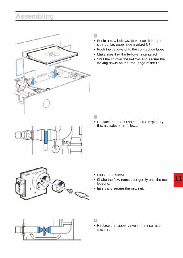
711
Assembling
%
• Put in a new bellows. Make sure it is rightside up, i.e. upper side marked UP.
• Push the bellows onto the connection tubes.• Make sure that the bellows is centered.• Shut the lid over the bellows and secure the
locking pawls on the front edge of the lid.
^
• Replace the fine mesh net in the expiratoryflow transducer as follows:
• Loosen the screw.• Shake the flow transducer gently until the net
loosens.• Insert and secure the new net.
&
• Replace the rubber valve in the inspirationchannel.

118
*
• Assemble the parts of the inspiration channel.• Put a new pressure transducer tube and
bacteria filter on the pipe of the inspirationchannel (see picture).
(
• Push the inspiration channel down intoposition and thread the silicone rubber bendonto its supporting pin.
• Make sure that the inspiration valve iscorrectly positioned and that it is not bent ortwisted.
• Connect the filter to the pressure transducermarked INSP.
• Make sure that the pressure transducer tubeis not bent or pinched.
BL
• Connect the connector to the flow transducer.• Make sure that the serial numbers on the
transducer and on the connector agree.
Assembling

911
BM
• Replace the rubber valve in the expirationchannel.
BN
• Assemble the parts of the expiration channel.• Put a new pressure transducer tube and
bacteria filter on the pipe of the expirationchannel.
• Connect the filter to the pressure transducermarked EXP.
Assembling
BP
• Connect the connector to the flowtransducer.
• Make sure that the serial numbers on thetransducer and on the connector agree.
BQ
• Connect manual ventilation accessory,O2FLUSH quick-coupling (if required) andnew patient tubes.
Make sure that the bacteria filter is properlyconnected to the pressure transducer.Otherwise, the expiration could be blocked.
BO
• Push the expiration channel into position.Thread the silicone rubber bend onto itssupporting pin.
• Make sure that the expiration valve is notbent or twisted.
• Make sure that the pressure transducer tubeis not bent or pinched.

1110
Assembling
VOL. CONTR.
BR
• Note on the log sheet that a complete cleaninghas been carried out.
BS
• Calibrate the ventilator (see chapter 13).
BT
• Check/Calibrate the O2 cell (see chapter 12).
BU
• Carry out a check on functions (see chapter 6).
After autoclaving in certain autoclaves, the flowtransducers may be somewhat damp, and thismay give rise to incorrrect readings on theEXPIRED MINUTE VOLUME meter.
The moisture is removed in the followingway:• Connect the ventilator to mains.• Connect a test lung to the Y-piece.• Connect compressed air to the ventilator and
let it run for about 15 minutes with aPRESET INSP. MIN. VOLUME of 7.5 l/min.
• Store the ventilator under a cover in normalroom temperature and humidity.

112
112
Chapter 12
Sealed unit contains caustic. Leaked liquidmay cause severe burns to skin and eyes.In case of contact, immediately flush withplenty of water for at least 15 minutes. Foreyes, get medical attention.
Replacement ofO2 cellThe O2 cell is an expendable item. An indicationof an expended O2 cell is a deterioration of thelinearity and/or a rapid drop in the O2
concentration readings on the digital display. Toavoid alarm when the O2 cell is exhausted, theconnector at the top of the O2 cell must bedisconnected. If the O2 cell is removed, aplastic cover with an O-ring has to be put in itsplace.
In this chapter:
Replacement .................. 12:2Calibration...................... 12:2Log sheet ....................... 12:2

122
Replacement and calibration
Replacement!
Unpack the O2 cell at least 30 minutes beforereplacement/calibration.
@
Disconnect mains supply and compressed air.
#
Disconnect the connector at the top of theO2 cell.
$
Remove the O2 cell by turning it counter-clockwise.
%
Connect the ventilator to mains supply and let itrun for about 15 minutes.
^
Set the parameter selector at O2 CONC. %.
&
Depress the pushbutton and adjust withtrimmer 10 until the display reads 00.0.
*
Put the new O2 cell in place by turning itclockwise. Do not forget the O-ring at thebottom of the O2 cell.
(
Connect the connector at the top of the O2 cell.
Calibration of O2 cell!
Connect compressed air.
@
Set WORKING PRESSURE to 60 cm H2O.
#
The digital display should read 20.9%. If not,adjust with trimmer 9.
$
After about 24 hours, make sure that the O2 cellgives a stable reading (20.9% with compressedair connected). If the reading is not 20.9%,calibrate as described above.
Log sheet• Note on the log sheet that the O2 cell hasbeen replaced and calibrated.
O2 CONC. %

113
113
Chapter 13
CalibrationThe calibration must be carried out after the1000 hours overhaul and after completecleaning.
In this chapter:
1. Basic setting forcalibration ..................... 13:2
2. Check on mechanicalzeroing of instruments . 13:3
3. Balancing of flowtransducers ................... 13:3
4. Electric zeroing ............. 13:45. Gas supply and
working pressure.......... 13:46. Check of manometer
and for internal leakage 13:57. Pressure transducers... 13:58. Upper pressure limit,
airway pressure ............ 13:69. Triggering level ............. 13:6
10. Flow, inspiration side ... 13:611. Check for leakage,
(external) ....................... 13:712. Flow, expiration side .... 13:713. Volume alarms .............. 13:714. O2 cell ............................. 13:815. Log sheet....................... 13:8
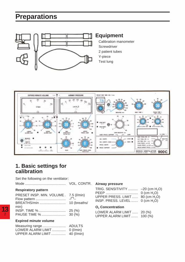
132
Preparations
Equipment• Calibration manometer• Screwdriver• 2 patient tubes• Y-piece• Test lung
1. Basic settings forcalibrationSet the following on the ventilator:Mode .......................................... VOL. CONTR.
Respiratory patternPRESET INSP. MIN. VOLUME . 7.5 (l/min)Flow pattern ............................... – –BREATHS/min ........................... 10 (breaths/min)INSP. TIME %............................ 25 (%)PAUSE TIME % ......................... 30 (%)
Expired minute volumeMeasuring range ........................ ADULTSLOWER ALARM LIMIT .............. 0 (l/min)UPPER ALARM LIMIT ............... 40 (l/min)
Airway pressureTRIG. SENSITIVITY .......... –20 (cm H2O)PEEP ................................. 0 (cm H2O)UPPER PRESS. LIMIT ...... 80 (cm H2O)INSP. PRESS. LEVEL ....... 0 (cm H2O)
O2 ConcentrationLOWER ALARM LIMIT ...... 20 (%)UPPER ALARM LIMIT ....... 100 (%)

313
Calibration
2. Check on mechanicalzeroing of instruments• During this check, the ventilator must not
be connected to mains or to a gas supply.• Check that the meters EXPIRED MINUTE
VOLUME and AIRWAY PRESSURE read 0.• If not, adjust the meters.
3. Balancing of flowtransducers• Open the lid on the pneumatic unit. Open the
lid above the trimmers (variable resistors).NOTE! The adjustment of trimmers is verysensitive. When adjusting, turn the trimmersvery slowly while watching the lamp.
List of trimmers
1. Exp. flow. Gain2. Exp. flow. Lamp3. Insp. flow. Gain4. Insp. flow. Lamp5. Exp. pressure. Gain6. Exp. pressure. 0-setting7. Insp. pressure. Gain8. Insp. pressure. 0-setting9. O2 %
10. O2, 0 volt
• Connect the ventilator to mains.• Set the mains switch on the rear of the
ventilator to on. Make sure that the greenlamp POWER ON lights up when you switchon.
• Let the ventilator run at least 15 minutes.Then adjust:
a) Flow transducer on insp. side: Adjusttrimmer 4 until the lamp at trimmer 4 lightsup.
b) Flow transducer on exp. side: Adjust trimmer2 until the lamp at trimmer 2 lights up.

134
Calibration
4. Electric zeroinga) Airway pressure (pressure transducer ofinsp. side)• Check that the meter AIRWAY PRESSURE
reads 0.• If not, adjust with trimmer 8.
b) Airway pressure (pressure transducer ofexp. side)• Keep the pushbutton depressed and at the
same time check that the meter reads 0.• If not, adjust the reading (with pushbutton
depressed) with trimmer 6.
c) Expired minute volume• Set the parameter selector at EXP. MIN. VOL
l/min.• Check that the digital display and the meter
EXPIRED MINUTE VOLUME read 0. If not,the electronic unit is faulty and must berepaired by a service technician.
5. Gas supply and workingpressure• Connect compressed air.• Set the WORKING PRESSURE to
60 cm H2O.
EXP. MIN.VOL. l/min

513
Calibration
6. Check of manometer andfor internal leakage• Connect a calibration manometer to the
inspiration outlet pipe.• Block the calibration manometer.• Check that the manometer WORKING
PRESSURE gives the same reading as thecalibration manometer (60 ± 2 cm H2O).If not, replace the WORKING PRESSUREmanometer.
• The reading on the meter AIRWAYPRESSURE should not fall more than a fewcm H2O during the time the inspiration valveis closed. If the reading falls more, look forleakage.
• Remove the calibration manometer.• Connect a patient tube from the inspiration
outlet to the expiration inlet.• Keep the expiration valve closed.• The reading on the meter AIRWAY
PRESSURE should not fall more than a fewcm H2O during the time the inspiration valveis closed. If the reading falls more, look forleakage in the expiration channel.
7. Pressure transducersa) Inspiration side• Keep the expiration valve closed.• Check that the meter AIRWAY PRESSURE
gives the same reading as the manometerWORKING PRESSURE (60 ± 1 cm H2O).
• If not, adjust with trimmer 7.
b) Expiration side• Keep the expiration valve closed and
depress the pushbutton.• Check that the meter AIRWAY PRESSURE
gives the same reading as the manometerWORKING PRESSURE (60 ± 1 cm H2O).
• If not, adjust with trimmer 5.

136
Calibration
UPPER PRESS. LIMIT
TRIG. SENSITIVITY
8. Upper pressure limit,airway pressure• Block the inspiration outlet.• Turn the knob UPPER PRESS. LIMIT slowly
counter-clockwise from the position80 cm H2O until you reach the exact positionwhere the alarm lamp for UPPER PRESS.LIMIT flashes. At this instant, the readingsfor WORKING PRESSURE and AIRWAYPRESSURE should agree with the knobsetting ±3 cm H2O. If not, the electronic unitis faulty and must be repaired by a servicetechnician.
• Turn the knob back to 80 cm H2O.
9. Triggering level• Remove your hand from the inspiration
outlet.• Set the TRIG. SENSITIVITY to -10 cm H2O.• Turn the PEEP knob and check that the
TRIG. lamp lights up when +10 ±2 cm H2O ispassed. If not, the electronic unit is faulty andmust be repaired by a service technician.
• Reset TRIG. SENSITIVITY to -20 cm H2Oand PEEP to 0 cm H2O.
10. Flow, inspiration side• Set BREATHS/min to 5.• Connect a calibration manometer to the
inspiration outlet.• Let compressed air blow through the
calibration manometer for a few minutes.• Check that the reading on the calibration
manometer is 45 ±5 cm H2O duringinspiration.
• If not, adjust with trimmer 3.• Check that the lamp at trimmer 4 lights up at
pause and expiration. If not, repeatcalibration according to 3a.
• After 6-8 breaths, make sure that thecalibration manometer reading is stable(45 ±5 cm H2O).
• Remove the calibration manometer.

713
Calibration
11. Check for leakage(external)• Set BREATHS/min to 10.• Connect tubes and Y-piece.• Block the Y-piece.• Make sure that the AIRWAY PRESSURE
does not fall more than a few cm H2O duringpause.
12. Flow, expiration side• Set the respiratory rate at 20 BREATHS/min
and PAUSE TIME at 10%.• Connect a test lung.• Set the parameter selector at EXP. MIN.
VOL. l/min.• Let the ventilator run for a few minutes.• Check that the digital display shows
7.5 ±0.1 l/min.• If not, adjust with trimmer 1.• The difference between the digital display
and the meter EXPIRED MINUTE VOLUMEmust not be more than ±0.5 l/min.
• Check that the lamp at trimmer 2 lights up atinspiration and pause. If not, repeatcalibration according to 3B.
• After 6-8 breaths, make sure that the readingis stable.
13. Volume alarmsLower alarm limit• Turn the knob LOWER ALARM LIMIT to
7.5 l/min and make sure that the alarm isactivated at 7.5 ±0.5 l/min.
• Turn the knob LOWER ALARM LIMIT to0 l/min.
Upper alarm limit• Turn the knob UPPER ALARM LIMIT to
7.5 l/min and make sure that the alarm isactivated at 7.5 ±0.5 l/min.
• Turn the knob UPPER ALARM LIMIT to40 l/min.
EXP. MIN.VOL. l/min
MIN. VOL. ALARM LIMITS

138
14. O2 cell• Set the parameter selector at O2 CONC. %.• The digital display should read 20.9% (with
compressed air connected and WORKINGPRESSURE 60 cm H2O).
• If not, adjust with trimmer 9.• Normally, trimmer 10 needs not to be
adjusted. If necessary, see chapter 12.• Make sure that the UPPER ALARM LIMIT
and LOWER ALARM LIMIT are functioningcorrectly.
15. Log sheet• Note on the log sheet that the ventilator has
been calibrated.
O2 CONC. %
Calibration

114
Chapter 14
Technicalspecifications
In this chapter:
Gas and power supply .. 14:2Ventilation parametersand controls ................... 14:2Special functions........... 14:2Monitoring ...................... 14:2Alarm and indicators..... 14:3General ........................... 14:4

142
Technical specifications
Gas and power supplyGas .................................................................... Must fulfill specifications for medical gases.Gas consumption ............................................... Approximately equal to preset inspiratory
minute volume or equal to flow meter setting.Gas supply via high pressure inlet .................... From central gas supply, compressor or gas
cylinder.Electronic gas supply unit, inlet pressure.......... 2.5-5 bar (250-500 kPa).Other gas supply unit, inlet pressure ................ 2.5-7 bar (250-700 kPa).Gas supply via low pressure inlet ...................... From flowmeter(s).Power supply ..................................................... (100), 110 120 220 240 V ±10%, 50 or 60 Hz.Power consumption ........................................... Approximately 40 W.
Ventilation controls,control rangesWorking pressure .............................................. Up to 120 cm H2O.Modes ................................................................ VOL. CONTR. (Volume controlled).
VOL. CONTR. + SIGH (Volume controlled withsigh). PRESS. CONTR. (Pressure controlled).PRESS. SUPPORT (Pressure support). SIMV(Synchronized Intermittent MandatoryVentilation). SIMV + PRESS. SUPPORT.CPAP (Continuous Positive Airway Pressure).MAN. (Manual ventilation—auxiliary equipmentnecessary).
Preset inspiratory minute volume ...................... 0.5-40 l/min. With sufficient working pressure.Accuracy (for momentary insp. flow up to1.6 l/s): ±10% or 0.2 l/min.
Flow pattern ....................................................... Constant or accelerating.Respiratory rate ................................................. 5-120 breaths/minute.Inspiration time .................................................. 20, 25, 33, 50 or 80% of the respiratory cycle.Pause time ......................................................... 0, 5, 10, 20 or 30% of the respiratory cycle.Inspiratory pressure (above PEEP) ................... 0-100 cm H2O.PEEP ................................................................. 0-50 cm H2O.Upper pressure limit .......................................... 15-120 cm H2O.Trig sensitivity (below PEEP) ............................ -20-0 cm H2O.SIMV-rate ........................................................... HIGH RATE (4-40 SIMV breaths/min). LOW
RATE (0.4-4 SIMV breaths/min.).Sigh .................................................................... Double tidal volume every hundredth breath.Compressible volume (internal) ........................ 0.075 l.
Special functionsInspiratory pause holdExpiratory pause holdGas change
MonitoringAnalog presentation
Airway pressure ................................................. Range -20-120 cm H2O.Accuracy: ±5% or ±2 cm H2O.
314
Expired minute volume ...................................... ADULTS range 0-40 l/min. Accuracy (formomentary exp. flow up to 1.6 l/s): ±5% or±0.5 l/min. INFANTS range 0-4 l/min. Accuracy(for momentary exp. flow up to 1.6 l/s): ±5% or±0.2 l/min.
Digital presentation
Respiratory rate ................................................. Range 5-120 breaths/min. Accuracy (incontrolled ventilation: ± 10% or ± 1 breath/min.
O2 concentration ................................................ Presented in % by volume; Range 20-100%.Accuracy (applying for the barometric pressureand working pressure at which the O2 cell iscalibrated): ±5% of read value.
Inspired tidal volume.......................................... Range 0-1999 ml. Accuracy (for momentaryinsp flow up to 1.6 l/s): ±10% or 0.2 l/min.
resp. rate.
Expired tidal volume .......................................... Range 0-1999 ml. Accuracy (for momentaryexp, flow up to 1.6 l/s): ±5% or 0.2 l/min.
resp. rate.Expired minute volume ...................................... ADULTS range 0-40 l/min. INFANTS range
0-4 l/min. Accuracy (for momentary exp. flowup to 1.6 l/s): ±5% or ±0.2 l/min.
Peak pressure .................................................... Range 0-120 cm H2O. Accuracy: ±5% or±2 cm H2O.
Pause pressure.................................................. Range 0-120 cm H2O. Accuracy: ±5% or±2 cm H2O.
Mean airway pressure ....................................... Range 0-120 cm H2O. Accuracy: ±5% or±2 cm H2O.
Alarms and indicatorsPush button 2 min. ........................................ Audible signals, below marked *, muted for
2 minutes. (max).AlarmsGas supply alarm ............................................... Flashing red light, audible * signal. Inoperative
at respiratory rates higher than 80 breaths/minute and INSP. TIME % 20 or 25.
Apnea alarm ...................................................... The APNEA ALARM is activated with audible* signals and flashing light if the time betweenany two consecutive breaths, spontaneousor mandatory or a combination of the two, isgreater than approximately 15 seconds (4breaths/min or less). The APNEA ALARM isnot intended to and will not monitor fordisconnections. The APNEA ALARM isoperative in CPAP, PRESS. SUPPORT, SIMV,and SIMV + PRESS. SUPPORT.
Expired minute volume ...................................... Flashing red light, audible * signal.O2 concentration ................................................ Flashing red light, audible * signal.Upper pressure limit .......................................... Red light, audible * signal.Power failure ...................................................... Green light POWER ON goes out, audible
signal for approximately 5 minutes.
Technical specifications

144
Technical specifications
Indicators
Set minute volume alarm ................................... Alarm limit unset: Flashing yellow light.Set O2 alarm ...................................................... Alarm limit unset: Flashing yellow light.Pressure support ............................................... Mode indication: Yellow light.CPAP ................................................................. Mode indication: Yellow light.MAN ................................................................... Mode indication: Yellow light.SIMV, HIGH/LOW RATE ................................... Mode and range indication: Two yellow lights.Expired minute volume INFANTS ..................... Range indication: Yellow light.Patient trig .......................................................... Trig indication: Yellow light.
General
Maximum working pressure .............................. 120 cm H2O.
Dimensions ........................................................ W50 × D23 × H32 cm.Weight ................................................................ Approximately 19 kg.
Specified accuracies apply for medical air andimply that the ventilator is calibrated accordingto the Operating Manual. For accuraciesspecified in more than one way, the highestvalue applies.

514
• SV 900 is an intensive care/anesthetic ventilator intended for adults,pediacrics andneonates.
• The device, if marked with the CE-symbol (including the number of thenotified body) shown to the left, complies with the requirements ofthe Medical Device Directive 93/42/EEC.
• Classification according to IEC 601:
Class I equipment
Type B
Continuous operation
• Symbols on the equipment:
Type B according to IEC 601.
Attention, consult Operating Manual
Alternating current
On (Power: Connection to mains)
Off (Power: Disconnection from mains)
• A device to monitor the concentration of anesthetic agents in the inspiratory gasshall be used during anesthesia.
• All measured and set parameters are referenced to ATP (Ambient Temperatureand Pressure).
• Old non-functioning O2 cells must be returned to the plae of purchase or
to a place where they can be disposed of properly. O2 cells must not be
disposed of with ordinary waste.
0413

Servo Ventilator 900 C – Operating Manual.Order No.: 69 78 761 E313E.© Maquet Critical Care AB, 1997-2001. All rights reserved. No part of this publication maybe reproduced, strred in a retrival system, or transmitted in any form or by any means, electronic, mechanical,photocopying, recording, or otherwise, without the prior permission of the copyright owner in writing.Subject to alterations without prior notice.Issued by Maquet Critical Care AB, SE-171 95 SOLNA, Sweden.
Printed in SwedenPrice: Group 0
0803.0.69th English edition, August 1997

SE
RV
O V
EN
TILAT
OR
900 C –
OP
ER
ATIN
G M
AN
UA
L


