Servicio de Att. al Cliente 16
30
Servicio de Att. al Cliente +34 986 288118 16 Technical Appendix The technical information guide for our entire product range 390 Polígono Industrial O Rebullón s/n. 36416 - Mos - España - [email protected] Servicio de Att. al Cliente +34 986 288118
Transcript of Servicio de Att. al Cliente 16
Polígono Industrial O Rebullón s/n. 36416 - Mos - España - [email protected]
Servicio de Att. al Cliente+34 986 288118
16Technical Appendix
The technical information guide for our entire product range
390
Polígono Industrial O Rebullón s/n. 36416 - Mos - España - [email protected]
Servicio de Att. al Cliente+34 986 288118
Polígono Industrial O Rebullón s/n. 36416 - Mos - España - [email protected]
Servicio de Att. al Cliente+34 986 288118
The length of certain hose types may alter due to
the influence of variable factors such as pressure,
vacuum, media temperature and ambient tempera-
ture. This must be taken into account when installing
hoses in order to prevent mechanical damage.
Case studies are in accordance with DIN 20 066,
section 4.
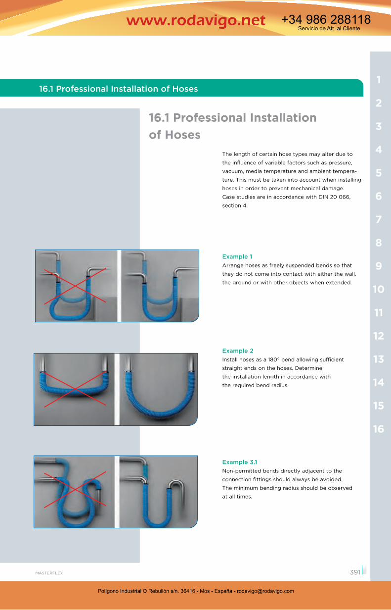
Example 1Arrange hoses as freely suspended bends so that
they do not come into contact with either the wall,
the ground or with other objects when extended.
Example 2Install hoses as a 180° bend allowing sufficient
straight ends on the hoses. Determine
the installation length in accordance with
the required bend radius.
Example 3.1Non-permitted bends directly adjacent to the
connection fittings should always be avoided.
The minimum bending radius should be observed
at all times.
16.1 Professional Installation of Hoses
16
15
14
13
12
11
10
9
8
7
6
5
4
3
2
1
391
16.1 Professional Installation of Hoses
Polígono Industrial O Rebullón s/n. 36416 - Mos - España - [email protected]
Servicio de Att. al Cliente+34 986 288118
Polígono Industrial O Rebullón s/n. 36416 - Mos - España - [email protected]
Servicio de Att. al Cliente+34 986 288118
Technical Appendix
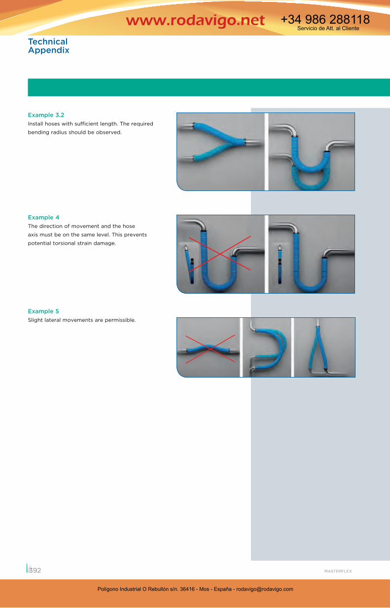
Example 3.2Install hoses with sufficient length. The required
bending radius should be observed.
Example 4The direction of movement and the hose
axis must be on the same level. This prevents
potential torsional strain damage.
Example 5Slight lateral movements are permissible.
392
Polígono Industrial O Rebullón s/n. 36416 - Mos - España - [email protected]
Servicio de Att. al Cliente+34 986 288118
Polígono Industrial O Rebullón s/n. 36416 - Mos - España - [email protected]
Servicio de Att. al Cliente+34 986 288118
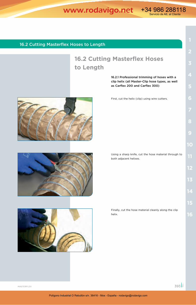
16.2.1 Professional trimming of hoses with a clip helix (all Master-Clip hose types, as well as Carflex 200 and Carflex 300)
First, cut the helix (clip) using wire cutters.
Using a sharp knife, cut the hose material through to
both adjacent helixes.
Finally, cut the hose material cleanly along the clip
helix.
16.2 Cutting Masterflex Hoses to Length
16.2 Cutting Masterflex Hoses to Length
16
15
14
13
12
11
10
9
8
7
6
5
4
3
2
1
393
Polígono Industrial O Rebullón s/n. 36416 - Mos - España - [email protected]
Servicio de Att. al Cliente+34 986 288118
Polígono Industrial O Rebullón s/n. 36416 - Mos - España - [email protected]
Servicio de Att. al Cliente+34 986 288118
MASTERFLEX – Dezember 2016
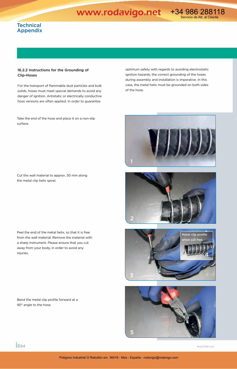
Take the end of the hose and place it on a non-slip
surface.
Cut the wall material to approx. 30 mm along
the metal clip helix spiral.
Peel the end of the metal helix, so that it is free
from the wall material. Remove the material with
a sharp instrument. Please ensure that you cut
away from your body, in order to avoid any
injuries.
Bend the metal clip profile forward at a
90° angle to the hose.
16.2.2 Instructions for the Grounding of Clip-Hoses
For the transport of flammable dust particles and bulk
solids, hoses must meet special demands to avoid any
danger of ignition. Antistatic or electrically conductive
hose versions are often applied. In order to guarantee
optimum safety with regards to avoiding electrostatic
ignition hazards, the correct grounding of the hoses
during assembly and installation is imperative. In this
case, the metal helix must be grounded on both sides
of the hose.
Metal clip profile
when cut free
1
2
3
4
5
394
Technical Appendix
Polígono Industrial O Rebullón s/n. 36416 - Mos - España - [email protected]
Servicio de Att. al Cliente+34 986 288118
Polígono Industrial O Rebullón s/n. 36416 - Mos - España - [email protected]
Servicio de Att. al Cliente+34 986 288118
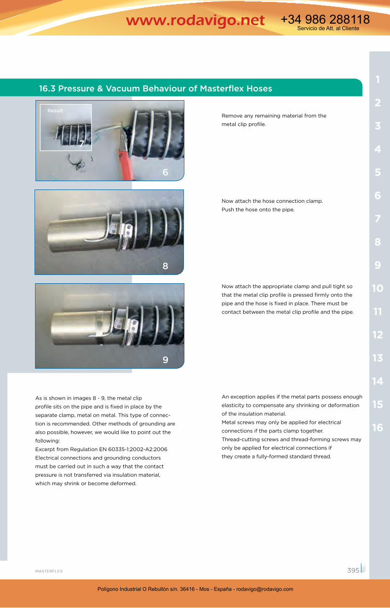
Remove any remaining material from the
metal clip profile.
Now attach the hose connection clamp.
Push the hose onto the pipe.
Now attach the appropriate clamp and pull tight so
that the metal clip profile is pressed firmly onto the
pipe and the hose is fixed in place. There must be
contact between the metal clip profile and the pipe.
Result
As is shown in images 8 - 9, the metal clip
profile sits on the pipe and is fixed in place by the
separate clamp, metal on metal. This type of connec-
tion is recommended. Other methods of grounding are
also possible, however, we would like to point out the
following:
Excerpt from Regulation EN 60335-1:2002-A2:2006 Electrical connections and grounding conductors
must be carried out in such a way that the contact
pressure is not transferred via insulation material,
which may shrink or become deformed.
An exception applies if the metal parts possess enough
elasticity to compensate any shrinking or deformation
of the insulation material.
Metal screws may only be applied for electrical
connections if the parts clamp together.
Thread-cutting screws and thread-forming screws may
only be applied for electrical connections if
they create a fully-formed standard thread.
6
7
8
9
16
15
14
13
12
11
10
9
8
7
6
5
4
3
2
1
395
16.3 Pressure & Vacuum Behaviour of Masterflex Hoses
Polígono Industrial O Rebullón s/n. 36416 - Mos - España - [email protected]
Servicio de Att. al Cliente+34 986 288118
Polígono Industrial O Rebullón s/n. 36416 - Mos - España - [email protected]
Servicio de Att. al Cliente+34 986 288118
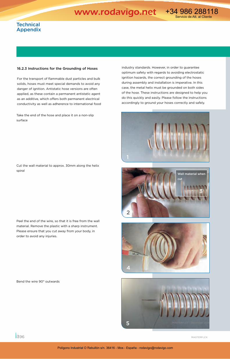
Take the end of the hose and place it on a non-slip
surface
Cut the wall material to approx. 30mm along the helix
spiral
Peel the end of the wire, so that it is free from the wall
material. Remove the plastic with a sharp instrument.
Please ensure that you cut away from your body, in
order to avoid any injuries.
Bend the wire 90° outwards
16.2.3 Instructions for the Grounding of Hoses
For the transport of flammable dust particles and bulk
solids, hoses must meet special demands to avoid any
danger of ignition. Antistatic hose versions are often
applied, as these contain a permanent antistatic agent
as an additive, which offers both permanent electrical
conductivity as well as adherence to international food
industry standards. However, in order to guarantee
optimum safety with regards to avoiding electrostatic
ignition hazards, the correct grounding of the hoses
during assembly and installation is imperative. In this
case, the metal helix must be grounded on both sides
of the hose. These instructions are designed to help you
do this quickly and easily. Please follow the instructions
accordingly to ground your hoses correctly and safely.
Wall material when
cut
1
2
3
4
5
2
MASTERFLEX – Dezember 2016
396
Technical Appendix
Polígono Industrial O Rebullón s/n. 36416 - Mos - España - [email protected]
Servicio de Att. al Cliente+34 986 288118
Polígono Industrial O Rebullón s/n. 36416 - Mos - España - [email protected]
Servicio de Att. al Cliente+34 986 288118
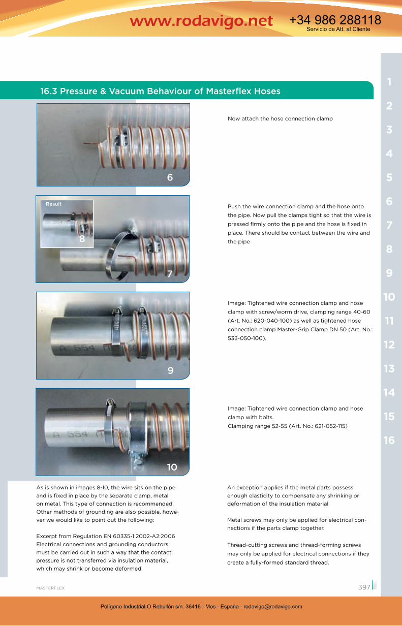
Now attach the hose connection clamp
Push the wire connection clamp and the hose onto
the pipe. Now pull the clamps tight so that the wire is
pressed firmly onto the pipe and the hose is fixed in
place. There should be contact between the wire and
the pipe
Image: Tightened wire connection clamp and hose
clamp with screw/worm drive, clamping range 40-60
(Art. No.: 620-040-100) as well as tightened hose
connection clamp Master-Grip Clamp DN 50 (Art. No.:
533-050-100).
Image: Tightened wire connection clamp and hose
clamp with bolts.
Clamping range 52-55 (Art. No.: 621-052-115)
Result
An exception applies if the metal parts possess enough elasticity to compensate any shrinking or deformation of the insulation material.
Metal screws may only be applied for electrical con-nections if the parts clamp together.
Thread-cutting screws and thread-forming screws
may only be applied for electrical connections if they
create a fully-formed standard thread.
6
7
9
8
10
As is shown in images 8-10, the wire sits on the pipe and is fixed in place by the separate clamp, metal on metal. This type of connection is recommended. Other methods of grounding are also possible, howe-ver we would like to point out the following:
Excerpt from Regulation EN 60335-1:2002-A2:2006Electrical connections and grounding conductors must be carried out in such a way that the contact pressure is not transferred via insulation material, which may shrink or become deformed.
16
15
14
13
12
11
10
9
8
7
6
5
4
3
2
1
397
16.3 Pressure & Vacuum Behaviour of Masterflex Hoses
Polígono Industrial O Rebullón s/n. 36416 - Mos - España - [email protected]
Servicio de Att. al Cliente+34 986 288118
Polígono Industrial O Rebullón s/n. 36416 - Mos - España - [email protected]
Servicio de Att. al Cliente+34 986 288118
Technical Appendix
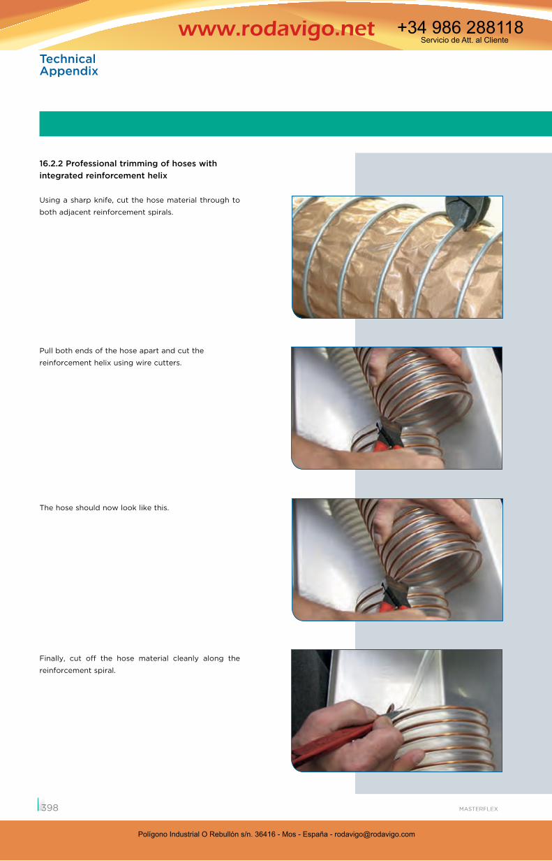
16.2.2 Professional trimming of hoses with integrated reinforcement helix
Using a sharp knife, cut the hose material through to
both adjacent reinforcement spirals.
Pull both ends of the hose apart and cut the
reinforcement helix using wire cutters.
The hose should now look like this.
Finally, cut off the hose material cleanly along the
reinforcement spiral.
398
Polígono Industrial O Rebullón s/n. 36416 - Mos - España - [email protected]
Servicio de Att. al Cliente+34 986 288118
Polígono Industrial O Rebullón s/n. 36416 - Mos - España - [email protected]
Servicio de Att. al Cliente+34 986 288118
GeneralAll catalogue details are the result of internal tests
and experimentation in accordance with international
standardisation recommendations and relate to a
media and ambient temperature of + 20 ºC. Different
temperatures may alter the pressure and
vacuum details. Depending on the construction
design, the effects of the pressure, vacuum, media
temperature and ambient temperature may alter the
length of certain hose types. This change in length
must be taken into account by the user during
operation. (See also Chapter 16.1 “Professional
Installation of Hoses“).
Operating PressureThe operating pressure is the maximum permitted
overpressure of a hose, at which it can be used. The
definition of the operating pressure is in accordance
with DIN EN ISO 7751.
Test PressureThe test pressure is up to 50 % above the opera-
ting pressure, depending on the hose construction
design. At test pressure, the hose must not have
any leaks and/or permanent deformations. The
definition of the test pressure is in accordance with
DIN EN ISO 7751.
Burst PressureThe burst pressure is the pressure at which the hose
is destroyed. The burst pressure is used to determine
the operating pressure taking into account the usual
safety factors. The definition of the burst pressure is
in accordance with DIN EN ISO 7751.
16.3 Pressure & Vacuum Behaviour of Masterflex Hoses
16.3 Pressure & Vacuum Behaviour of Masterflex Hoses
Vacuum (Negative Pressure)The definition of the vacuum details for Masterflex
hoses is in accordance with DIN 20024, point 15.
Testing the Vacuum ResistanceDuring the vacuum tests, the hoses are placed in a
90° arc in compliance with the minimum bending
radius. Vacuum is then applied until they show signs
of indentations or collapse. The permitted vacuum in
continuous operation is determined by taking into
account the usual general safety factors.
16
15
14
13
12
11
10
9
8
7
6
5
4
3
2
1
399
Polígono Industrial O Rebullón s/n. 36416 - Mos - España - [email protected]
Servicio de Att. al Cliente+34 986 288118
Polígono Industrial O Rebullón s/n. 36416 - Mos - España - [email protected]
Servicio de Att. al Cliente+34 986 288118
TechnicalAppendix
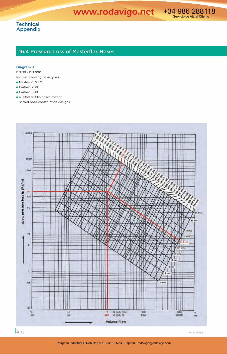
16.4 Pressure Loss of Masterflex Hoses
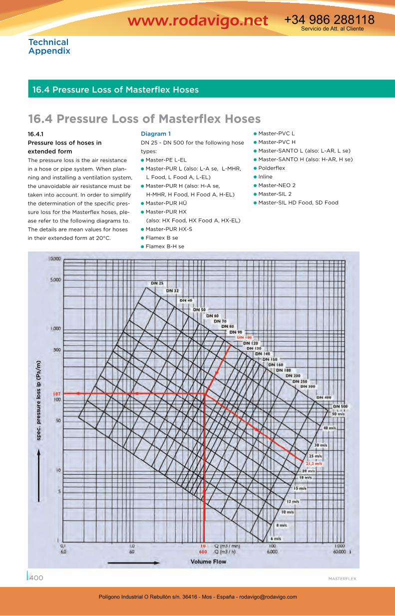
16.4.1 Pressure loss of hoses in extended formThe pressure loss is the air resistance
in a hose or pipe system. When plan-
ning and installing a ventilation system,
the unavoidable air resistance must be
taken into account. In order to simplify
the determination of the specific pres-
sure loss for the Masterflex hoses, ple-
ase refer to the following diagrams to.
The details are mean values for hoses
in their extended form at 20°C.
Diagram 1DN 25 - DN 500 for the following hose
types:
Master-PE L-EL
Master-PUR L (also: L-A se, L-MHR,
L Food, L Food A, L-EL)
Master-PUR H (also: H-A se,
H-MHR, H Food, H Food A, H-EL)
Master-PUR HÜ
Master-PUR HX
(also: HX Food, HX Food A, HX-EL)
Master-PUR HX-S
Flamex B se
Flamex B-H se
Master-PVC L
Master-PVC H
Master-SANTO L (also: L-AR, L se)
Master-SANTO H (also: H-AR, H se)
Polderflex
Inline
Master-NEO 2
Master-SIL 2
Master-SIL HD Food, SD Food
16.4 Pressure Loss of Masterflex Hoses
400
Polígono Industrial O Rebullón s/n. 36416 - Mos - España - [email protected]
Servicio de Att. al Cliente+34 986 288118
Polígono Industrial O Rebullón s/n. 36416 - Mos - España - [email protected]
Servicio de Att. al Cliente+34 986 288118
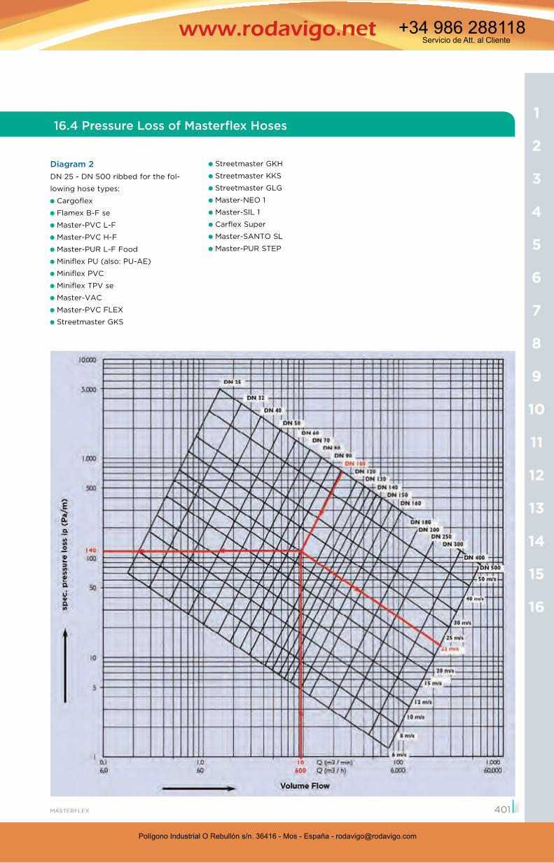
Miniflex PU
Diagram 2DN 25 - DN 500 ribbed for the fol-
lowing hose types:
Cargoflex
Flamex B-F se
Master-PVC L-F
Master-PVC H-F
Master-PUR L-F Food
Miniflex PU (also: PU-AE)
Miniflex PVC
Miniflex TPV se
Master-VAC
Master-PVC FLEX
Streetmaster GKS
Streetmaster GKH
Streetmaster KKS
Streetmaster GLG
Master-NEO 1
Master-SIL 1
Carflex Super
Master-SANTO SL
Master-PUR STEP
16.4 Pressure Loss of Masterflex Hoses
16
15
14
13
12
11
10
9
8
7
6
5
4
3
2
1
401
Polígono Industrial O Rebullón s/n. 36416 - Mos - España - [email protected]
Servicio de Att. al Cliente+34 986 288118
Polígono Industrial O Rebullón s/n. 36416 - Mos - España - [email protected]
Servicio de Att. al Cliente+34 986 288118
Technical Appendix
Diagram 3DN 38 - DN 900
for the following hose types:
Master-VENT 2
Carflex 200
Carflex 300
all Master-Clip hoses except
scaled hose construction designs
16.4 Pressure Loss of Masterflex Hoses
402
Polígono Industrial O Rebullón s/n. 36416 - Mos - España - [email protected]
Servicio de Att. al Cliente+34 986 288118
Polígono Industrial O Rebullón s/n. 36416 - Mos - España - [email protected]
Servicio de Att. al Cliente+34 986 288118
L=10 mv=21,2 m/s
R= 400 mm
R= 160 m
m
180
°
16.4 Pressure Loss of Masterflex Hoses
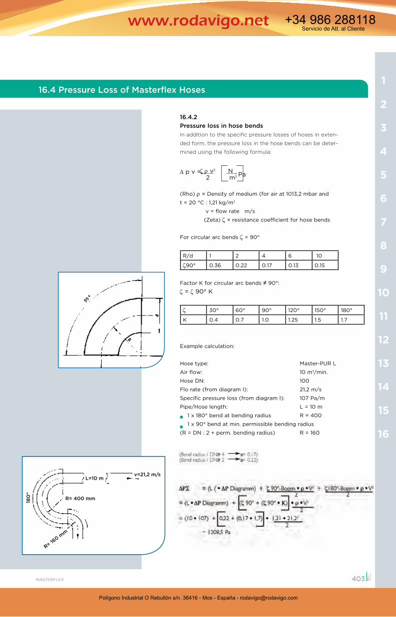
16.4.2Pressure loss in hose bendsIn addition to the specific pressure losses of hoses in exten-
ded form, the pressure loss in the hose bends can be deter-
mined using the following formula:
p v =
(Rho) = Density of medium (for air at 1013,2 mbar and
t = 20 °C : 1,21 kg/m3
v = flow rate m/s
(Zeta) = resistance coefficient for hose bends
For circular arc bends = 90°
R/d 1 2 4 6 10
90° 0.36 0.22 0.17 0.13 0.15
Factor K for circular arc bends 90°:
= 90° K
30° 60° 90° 120° 150° 180°
K 0.4 0.7 1.0 1.25 1.5 1.7
Example calculation:
Hose type: Master-PUR L
Air flow: 10 m3/min.
Hose DN: 100
Flo rate (from diagram I): 21,2 m/s
Specific pressure loss (from diagram I): 107 Pa/m
Pipe/Hose length: L = 10 m
1 x 180° bend at bending radius R = 400
1 x 90° bend at min. permissible bending radius
(R = DN : 2 + perm. bending radius) R = 160
v2 N = Pa 2 m2
16
15
14
13
12
11
10
9
8
7
6
5
4
3
2
1
403
Polígono Industrial O Rebullón s/n. 36416 - Mos - España - [email protected]
Servicio de Att. al Cliente+34 986 288118
Polígono Industrial O Rebullón s/n. 36416 - Mos - España - [email protected]
Servicio de Att. al Cliente+34 986 288118
TechnicalAppendix
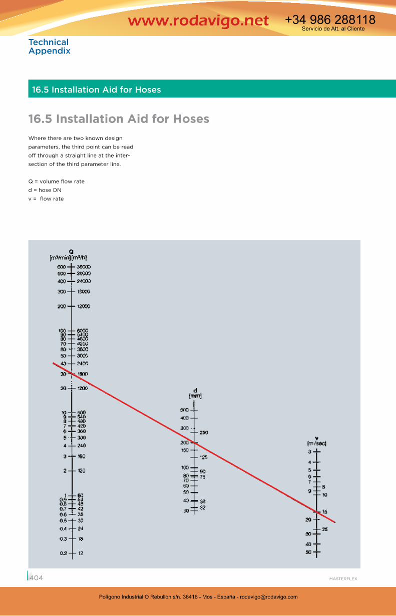
Where there are two known design
parameters, the third point can be read
off through a straight line at the inter-
section of the third parameter line.
Q = volume flow rate
d = hose DN
v = flow rate
16.5 Installation Aid for Hoses
16.5 Installation Aid for Hoses
404
Polígono Industrial O Rebullón s/n. 36416 - Mos - España - [email protected]
Servicio de Att. al Cliente+34 986 288118
Polígono Industrial O Rebullón s/n. 36416 - Mos - España - [email protected]
Servicio de Att. al Cliente+34 986 288118
16.6.1 Material description of Polyurethane (TPU)
The majority of the Masterflex suction and transport
hoses for abrasive solids are made from high perfor-
mance polyurethane.
Polyurethane is essentially created by the reaction of
three components with each other:
1. Polyole (long-chain diols)
2. Diisocyanates
3. Short-chain diols
The type of raw materials, the reaction conditions
and the proportions of the starting materials are
responsible for the product characteristics. The
applied polyols have a significant effect on specific
properties of the thermoplastic polyurethane. Either
polyester polyols or polyether polyols are used as
polyols. Thermoplastic polyurethane elastomers, also
known as TPU, have the quality and properties to
meet the most varied requirements such as:
Flexibility within a wide temperature range
Great durability
Kink/tear-resistant (high level of split and tear
resistance)
Good resilience and recoverability
Good dynamic stability under load
Hydrolysis and/or microbe resistance (for polyether
types or for modified polyester-types)
Good to very good resistance to atmospheric
corrosion
Resistance to oil, grease and solvents
16.6.2 Colour
The inherent colour is between yellowish and whitish
opaque or also translucent, although the wall thick-
ness is also a factor here. With increasing ageing of
the material, the yellowish discoloration increases
without adversely affecting the mechanical, thermal
and chemical properties. Colouring is possible.
17.6 Polyurethane (TPU)
16.6 Material description Polyurethane (TPU)
16.6.3 Mechanical properties
Resistance to further tearingResistance to further tearing means the resistance
of a notched test object to further tearing. The test
is carried out in accordance with DIN ISO 34-1. For
hoses made of polyurethane, this means that even
damaged hoses are less likely to tear further in
comparison to other thermoplastic hoses (e.g. PVC,
TPV, etc.).
Abrasion resistanceAbrasion in rubbers and elastomers is determined in
accordance with DIN ISO 4649. Here, a test sample is
forced with a certain pressure onto a rotating roller,
which is covered with a test emery paper. The full
friction length is approximately 40 m. The loss of
mass due to abrasive wear is measured with due
consideration of the thickness of the test sample and
the abrasive power of the test emery sheet. This is
indicated as a loss of volume in mm3. The standard
PUR material applied has an abrasion level of approx-
imately 25 - 30 mm3.
Comparative values of the raw materials used:
Rubber approx. 60 - 150 mm3
Soft-PVC approx. 100 mm3
TPV approx. 200 mm3
PUR-EL approx. 45 mm3
For further data, see 17.9.
Field tests have produced even greater differences
compared with the above materials, due to the
increased dampening and rebound elasticity of the
polyurethane material. The standardised test methods
do not fully reveal these differences.
16
15
14
13
12
11
10
9
8
7
6
5
4
3
2
1
405
Polígono Industrial O Rebullón s/n. 36416 - Mos - España - [email protected]
Servicio de Att. al Cliente+34 986 288118
Polígono Industrial O Rebullón s/n. 36416 - Mos - España - [email protected]
Servicio de Att. al Cliente+34 986 288118
TechnicalAppendix
16.6.4 Thermal propertiesLike all materials, TPU is subject to temperature
dependent, reversible alterations in length. This is
indicated by the coefficient of linear thermal expan-
sion a [ I/K ] and calculated in accordance with
DIN 53 752 in dependence of the temperature. Shore
hardness is also an influencing factor. It is therefore
advisable in many applications to take account of the
temperature dependence when selecting PUR hoses.
These hoses can be applied in temperatures up to
+125 °C for short periods, but a temperature of
+90 °C should not be exceeded for longer periods.
Soft polyether-based types are flexible in temperatu-
res down to -40 °C. Long-term tests of our processed
materials have shown that even with a permanent
temperature load in the limit range of +90 °C, only
insignificant effects on the mechanical properties
(heat ageing) occur.
16.6.5 Electrical properties Surface resistanceThe processed polyurethane material has a surface
resistance of approx. 1010 Ohm and can therefore be
used as electrically insulating protective hosing.
Dissipation of electrostatic chargesPlease refer to chap. 17.10
16.6.6 Media resistanceThe suitability of a plastic for a particular applica-
tion often depends on its resistance to chemicals.
The reaction of thermoplastic polyurethanes to the
effects of chemical substances can vary greatly. The
resistance of TPU to certain materials, e.g. cooling
and lubricating agents, depends on the additives in
these agents. The mechanical properties can change
when in contact with such agents.
Swelling of the polyurethane material is often due to
the effects of the media.
For the media resistance of TPU, please refer to the
resistance list at the end of this catalogue.
Microbe resistance, see chapter 17.12.
16.6.7 Weathering resistanceThe general resistance of TPU to ozone and ultra-
violet radiation is good (for further details, please see
chapter 16.12). The resistance of TPU to high-energy
radiation such as -, -, -radiation is superior to that
of most other plastics. The resistance to these kinds
of radiation depends among other things on the
dosage of the radiation, the form and dimensions of
the product, as well as the climate and atmosphere
in the location of the application. Certain properties,
such as resistance to thermo-forming and chemicals,
can be positively influenced by deliberate cross-
linking as a result of high-energy irradiation with the
aid of cross-linking agents.
16.6.8 Fire resistancePlastics, like all organic materials, are combustible.
The standard TPU we use is also inherently class-
ifiable as such. The fire resistance of a material is not,
however, a material property and it is influenced by
different criteria. The complexity of the influencing
factors makes it impossible to give a comprehensive
and generally applicable description of the fire resis-
tance of plastics, as the risk of combustion depends
on factors such as the wall thickness, form, quantity
and layout of combustible objects together with
other circumstances of use.
For this reason, the fire resistance of plastics should
not be described using words or phrases which may
be misinterpreted, such as “self-extinguishing“ or
“non-flammable“, but preferably by the relevant DIN
standard. Hoses with flame-inhibiting additives are
“hardly inflammable“ acc. to DIN 4102 B1 and are -
unlike most of our competitors‘ hoses - manufactured
from highly abrasion-resistant polyester TPU (and not
from polyether TPU).
16.6.9 Health assessmentThe raw materials used to produce the PUR hoses
comply with the statutory requirements for foodstuffs
(see chapter 16.11).
16.6 Polyurethane (TPU)
406
Polígono Industrial O Rebullón s/n. 36416 - Mos - España - [email protected]
Servicio de Att. al Cliente+34 986 288118
Polígono Industrial O Rebullón s/n. 36416 - Mos - España - [email protected]
Servicio de Att. al Cliente+34 986 288118
16.6.10 Hydrolysis resistance of PURThe polyurethanes processed by Masterflex are
permanently resistant to warm water up to max.
+40 °C. At higher temperatures, polyester-polyure-
thane displays an increasing impairment of its mecha-
nical material properties. Polyether-polyurethane,
however, is permanently resistant to hydrolytic
degradation.
16.6.11 Microbe resistance of PURAs result of our consistent state-of-the-art product
development, we have achieved a market first: not
only does our polyester polyurethane now have a
greater abrasion resistance, but is now also microbe-
resistant thanks to the use of special additives.
Microbes can quickly develop where there is ext-
ended contact with earth-like substances or
deposits of grass, foliage, sludge etc.. Moisture
combined with heat accelerates this process. The
enzymes released by the microbes result - without
appropriate treatment - in the splitting of the ester
compounds and the embrittlement of the plastic until
it falls apart. Polyether types are also resistant to
microbial attack, but their resistance to abrasion is
not as good - as described elsewhere.
The hoses manufactured by Masterflex from the
material TPV are produced from a thermoplastic
rubber.
Thermo-plastic rubber belongs to a group of elast-
omers, which excellently combine the performance
characteristics of vulcanisable rubbers, such as heat
resistance and low compression set, with the easy
processibility of thermo-plastics.
Thermo-plastic vulcanisate is a fully vulcanised poly-
olefin material. Production is carried out in a special
dynamic vulcanisation procedure, which produces
fully cross-linked rubber particles which in turn are
distributed in a continuous matrix of thermo-plastic
material.
The average rubber particle size of one micron or less
results in extremely good physical material proper-
ties.
TPV has a resistance to environmental conditions cor-
responding to the standard EPDM rubber mixtures,
whilst the chemical resistance is comparable to that
of chloroprene rubber mixtures.
The performance characteristics of thermoplastic
vulcanisates include:
mechanical properties over a temperature range of
-40 °C to +130 °C, peaks up to +150 °C
resistance to chemicals in the chloroprene class for
aqueous fluids, oils and hydrocarbons
low compression set and tension set
excellent hot air ageing behaviour at temperatures
of up to +150 °C at periods of up to two weeks and
up to +130 °C for longer periods
excellent dynamic fatigue resistance
outstanding resistance to ozone and weathering
The standard hoses are manufactured from black raw
materials, but can also be coloured in accordance
with customer requirements for appropriate delivery
quantities.
16.7 Thermoplastic Vulcanisate
16.7 Material Description Thermoplastic Vulcanisate (TPV)
16
15
14
13
12
11
10
9
8
7
6
5
4
3
2
1
407
Polígono Industrial O Rebullón s/n. 36416 - Mos - España - [email protected]
Servicio de Att. al Cliente+34 986 288118
Polígono Industrial O Rebullón s/n. 36416 - Mos - España - [email protected]
Servicio de Att. al Cliente+34 986 288118
TechnicalAppendix
16.8 Soft PVC (Polyvinyl Chloride)
PVC is one of the amorphous plastics. Nevertheless,
this material has excellent media resistance. For this
reason PVC hoses are frequently used for applica-
tions with problematical media or environments. Only
a number of solvents (aromatics, esters, ketones,
chlorinated hydrocarbons) attack it.
PVC is a cost-effective, versatile material, which does,
however, have the following disadvantages:
The temperature load capacity and the abrasion
resistance of PVC are significantly inferior to that of
PUR. Moreover, slow embrittlement of the material
arises on flexible hoses as a result of plasticiser mig-
ration, which can lead to premature failure.
Note:Highly toxic hydrochloric acid vapours and dioxins
are formed from PVC in the event of fire. These can
then constitute a significant health hazard, which may
even be fatal, and can destroy electronic equipment
through its corrosive effect.
16.8 Material Description Soft PVC (Polyvinyl Chloride)
408
Polígono Industrial O Rebullón s/n. 36416 - Mos - España - [email protected]
Servicio de Att. al Cliente+34 986 288118
Polígono Industrial O Rebullón s/n. 36416 - Mos - España - [email protected]
Servicio de Att. al Cliente+34 986 288118
16.9 Specifications of Applied Thermoplastic Raw Material
16.9 Specifications of Applied Thermoplastic Raw Materials
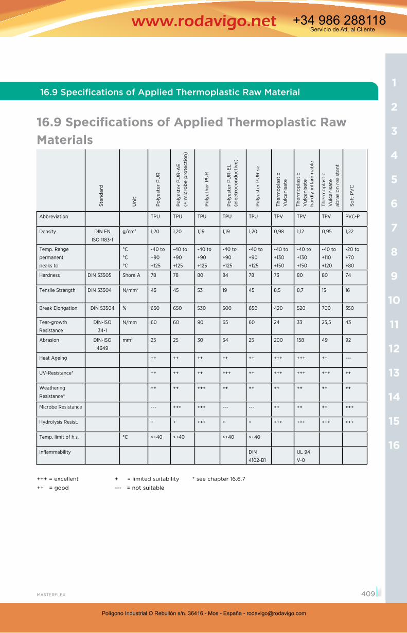
Abbreviation TPU TPU TPU TPU TPU TPV TPV TPV PVC-P
Density DIN EN
ISO 1183-1
g/cm3 1,20 1,20 1,19 1,19 1,20 0,98 1,12 0,95 1,22
Temp. Range
permanent
peaks to
°C
°C
°C
-40 to
+90
+125
-40 to
+90
+125
-40 to
+90
+125
-40 to
+90
+125
-40 to
+90
+125
-40 to
+130
+150
-40 to
+130
+150
-40 to
+110
+120
-20 to
+70
+80
Hardness DIN 53505 Shore A 78 78 80 84 78 73 80 80 74
Tensile Strength DIN 53504 N/mm2 45 45 53 19 45 8,5 8,7 15 16
Break Elongation DIN 53504 % 650 650 530 500 650 420 520 700 350
Tear-growth
Resistance
DIN-ISO
34-1
N/mm 60 60 90 65 60 24 33 25,5 43
Abrasion DIN-ISO
4649
mm3 25 25 30 54 25 200 158 49 92
Heat Ageing ++ ++ ++ ++ ++ +++ +++ ++ ---
UV-Resistance* ++ ++ ++ +++ ++ +++ +++ +++ ++
Weathering
Resistance*
++ ++ +++ ++ ++ ++ ++ ++ ++
Microbe Resistance --- +++ +++ --- --- ++ ++ ++ +++
Hydrolysis Resist. + + +++ + + +++ +++ +++ +++
Temp. limit of h.s. °C <+40 <+40 <+40 <+40
Inflammability DIN
4102-B1
UL 94
V-0
+++ = excellent
++ = good
+ = limited suitability
--- = not suitable
* see chapter 16.6.7
Sta
nd
ard
Un
it
Po
lyes
ter
PU
R
Po
lyes
ter
PU
R-A
E(+
mic
rob
e p
rote
ctio
n)
Po
lyet
her
PU
R
Po
lyes
ter
PU
R-E
L(e
lect
roco
nd
uct
ive)
Po
lyes
ter
PU
R s
e
Th
erm
op
last
icV
ulc
anis
ate
Th
erm
op
last
icV
ulc
anis
ate
har
dly
infl
amm
able
Th
erm
op
last
icV
ulc
anis
ate
abra
sio
n r
esis
tan
t
So
ft P
VC
16
15
14
13
12
11
10
9
8
7
6
5
4
3
2
1
409
Polígono Industrial O Rebullón s/n. 36416 - Mos - España - [email protected]
Servicio de Att. al Cliente+34 986 288118
Polígono Industrial O Rebullón s/n. 36416 - Mos - España - [email protected]
Servicio de Att. al Cliente+34 986 288118
TechnicalAppendix
16.10 Dissipation of Electrostatic Charges on Masterflex Hoses
16.10.1 GeneralHose lines can be a potential source of danger in pneu-
matic suction and conveying plants due to the build-up
of electrostatic charges. The capacity to dissipate
such charges is therefore mandatory in many areas of
application to ensure safe operation. Hoses are used to
transport solids (e.g. in the form of granular materials,
chippings, dust, sand, cement, etc.) as well as liquids
and gases. Electrostatic charges occur wherever solids,
which are non-conductive have poor conductivity, come
into contact with other materials and then separated
again. As a result of this friction and the subsequent
separation process, one material has fewer electrons
than the other, which leads to one being positively and
the other negatively charged. In the area of the common
boundary surface, the so-called “interfacial potential“ is
formed, which enables the discharging of sparks. There
are a number of ways to avoid such discharges and
these are described in more detail below.
16.10.2 RegulationsA series of directives and regulations exist for evaluating
and avoiding the risk of ignition as well as the approp-
riate safety precautions to be taken. At this point, we
refer primarily to the German Technical Rule for
Occupational Safety, TRGS 727 (ATEX) “Avoidance of
ignition hazards due to electrostatic charges”.
TRGS 727 (ATEX) was prepared by the German
Committee on Occupational Safety and published in the
Joint Ministerial Gazette by the German Federal Ministry
of Labour and Social Affairs.
The TRGS 727 replaces the former TRBS 2153 and
updates it.
Masterflex products also fulfill the relevant regulation of
harmonisation by the union: guideline 94/9/EG
(until 19. April 2016) and guideline 2014/34/EU (from
20. April 2016)
16.10.3 Causes of electrostatic chargesDuring the transportation of solids, liquids or gases, the
“interfacial potential“ previously described is generated
by the friction on the inside of the hose. Depending
on the degree of charge, this leads to sparks, electrical
breakdown or in some cases the ignition of flammable
materials. Aside from the intensity of the contact
(friction) between the medium and the inner sides of
the hose, the “dielectric permittivity“ of the hose and
medium is decisive for the extent to which charging is
possible. This is considered to be a measure of the
polarisability. Even conductive materials can become
charged if not earthed.
16.10.4 Ways of avoiding electrostatic chargesThe surface resistance of the hose wall materials can
be reduced to values between 103 and 104 Ohm. These
additives (e.g. conductive soot or “carbon black“) form
a network of conductive particles touching each other
in the plastic (volume conductivity). Such plastics are,
however, only available in black due to the colour of the
additives.
Another possibility is the addition of anti-static agents
to obtain a surface resistance of <109 Ohm and to
maintain the transparent colour of the basic material.
In certain anti-static agents, resistance is established by
humidity absorption in the hose wall surface. This can be
a disadvantage in some applications, e.g. the transport
of dry powders, since the humidity absorbed from the
air causes poor or insufficient anti-static properties.
Furthermore, the application-specific abrasion may
impair the establishment of the required surface resis-
tance. This is why anti-static hoses should be used in the
appropriate zones/applications. Ideally, these should be
equipped with permanent anti-static additives, which
are not dependent on any additional external aspects.
For secondary applications, such as “gases and liquids
of low conductivity” in Zone 1 and “non-combustible
dusts/bulk goods” in Zone 21, spiral/clip hoses can be
applied, if their wall material specifically offers a surface
resistance of > 109 Ohm. Here, it is important to note
that the helix/clip interval must be < 30 mm and the
helix overlap must be < 2 mm.
All of the applications mentioned above require both
helix/clip ends to be earthed to the connector to
ensure static dissipation. For further information on the
possible applications of Masterflex hoses, please refer to
the specific product data sheets.
16.10.5 Limit determination & definitionIn general, the following can become electrostatically
charged:
16.10 Dissipation of Electrostatic Charges on Masterflex Hoses
410
Polígono Industrial O Rebullón s/n. 36416 - Mos - España - [email protected]
Servicio de Att. al Cliente+34 986 288118
Polígono Industrial O Rebullón s/n. 36416 - Mos - España - [email protected]
Servicio de Att. al Cliente+34 986 288118
16.10 Dissipation of Electrostatic Charges on Masterflex Hoses
Hoses with a wire spiral
Solids with a surface resistance of >109 Ohm
All non-earthed objects made from electro-
conductive materials
In general, the following are not capable of becoming
electrostatically charged:
All solids and liquids, which fall short of the above
critical resistance values
All conductive materials which are earthed.
In practice, when using hose lines with a wire helix/
clip, this means the following:
1. Wire-reinforced hoses / clip hoses may be used
for “gases and liquids of low conductivity” in Zone 1
and “non-combustible dusts/bulk goods” in Zone 21
if their wall surface resistance is > 109 Ohm, the helix/
clip interval is < 30 mm and the overlap of the helix/
clip is < 2 mm. For the mounting and installation of
the hoses, it is important to ensure that both helix/
clip ends have an earthed connection.
2. Increased protection can be obtained by using
non-chargeable hoses, such as anti-static hoses with
a surface resistance of < 109 Ohm. Again, the exposed
helix/clip ends must have an earthed connection.
3. Electroconductive hoses with a surface resistance
of < 106 Ohm offer optimum safety. However, even
these hoses require an earthed connection between
the exposed ends of the wire and the electrocon-
ductive connection socket for safety reasons. Tested
Masterflex hoses with the addition “EL“ comply fully
with these requirements and are electroconductive to
< 104 Ohm.
16.10.6 Measurement methodThe determination of the surface resistance depends
on the relevant measurement method and is determi-
ned for non-conductive solids in accordance with DIN
IEC 60093 / VDE 0303, Section 30 (Test method for
electrically insulating materials, flow resistance and
specific surface resistance of solid, electrically insu-
lating materials). For rubber/plastic hoses and hose
lines, the standard DIN EN ISO 8031 - “Rubber and
plastic hoses and hose lines“ describes the determi-
nation of the electrical resistance.
This standard describes:
Procedures for hoses with conductive inner layers
(e.g. the method of measuring Masterflex hose
types Master-Clip ...)
Procedures for hoses with a conductive outer layer
Procedures for hoses made from a mixture of mate
rials, which are conductive throughout (e.g. the
measurement method for the profile-extruded
Masterflex hose types with “EL“).
16.10.7 NoteThe addition of conductive additives or anti-static
agents reduces the mechanical properties of the
material (e.g. resistance to abrasion and tearing) and
thus reduces service life. The information summarised
under points 1 to 6 is based on internal and external
field research and on the currently applicable regu-
lations. It serves as a guideline for using Masterflex
hose types in areas of potential danger but no gua-
rantee is given for its entireity.
The catalogue details relating to surface resistance
are based on official test results, details supplied
by our raw material suppliers and internal measure-
ments. In case of doubt, we recommend that users
test the hoses under operating conditions or similar
circumstances before final installation.
16
15
14
13
12
11
10
9
8
7
6
5
4
3
2
1
411
Polígono Industrial O Rebullón s/n. 36416 - Mos - España - [email protected]
Servicio de Att. al Cliente+34 986 288118
Polígono Industrial O Rebullón s/n. 36416 - Mos - España - [email protected]
Servicio de Att. al Cliente+34 986 288118
Technical Appendix
16.11 Food Law Requirements & Certifications
In order for hoses to be authorized for use within the
food industry, they must adhere to and fulfil the appro-
priate “food law regulations”. Masterflex produces hose
systems made from polyurethane and hoses made from
polyolefin, which fulfil all requirements:
16.11.1 Polyurethane hoses:
Hose Types: Master-PUR Flat L Food, Master-PUR Flat H Food,
Master-PUR Flat SH Food, Master-PUR L-F Food,
Master-PUR L Food, Master-PUR H Food,
Master-PUR HX Food, Polderflex PUR Food
or all hoses, which are made from the same material as
the hoses listed above with a wall thickness of
< 5.5 mm and an inner diameter of < 20 mm.
The raw materials used to produce Master-PUR Food
hoses comply with the following statutory requirements
for foodstuffs:
EUThe Master-PUR Food range has been tested and
certified by an independent institute.
The hoses included in the Master-PUR Food range fulfil
and are in accordance under certain conditions with the
requirements of the regulation (EU) No. 1935/2004, as
well as the regulation (EU) No. 10/2011 and 1282/2011,
the German Food and Feed Code (LFGB, from 15th
March 2012) and the Consumer Goods Ordinance (from
13th Dec. 2011).
For further information on the conditions, please refer to
the test certificate H-224987-12-Bg.
The raw materials applied are also listed in Chapter 2 of
the recommendation “XXXIX. Consumer Goods based
on Polyurethanes“ (from 1st Jan. 2012).
USAThe raw materials and additives used (excluding stabili-
sers) are listed in 21 CFR (Code of Federal Regulations)
§ 177.2600 “Rubber articles intended for repeated use“
of the FDA dated 01.04.2009. The antioxidants/
stabilisers used are listed in FDA 21 CFR § 178.2010
“Antioxidants and/or stabilizers for polymers“.
16.11.2 Hoses made from antistatic polyurethane
Hose Types:
Master-PUR L-F Food A, Master-PUR L Food A ,
Master-PUR H Food A, Master-PUR HX Food A,
Master-PUR HX-S Food A, Polderflex PUR Food A
or all hoses, which are made from the same material as
the hoses listed above with a wall thickness of > 0.4 mm
and an inner diameter of > 20 mm.
The raw materials used to produce Master-PUR Food A
hoses comply with the following statutory requirements
for foodstuffs:
EUThe Master-PUR Food A range has been tested and
certified by an independent institute.
The monomers used in the production of the raw
materials are listed in the commodities‘ regulation as
disclosed on 23.12.1997 (Official Federal Gazette 1998 1
S.5), amended on 23.09.2009 (Official Federal Gazette
IS 3130).
The monomers used are listed in the annexes to EC
Directive 2002/72/EC as amended in the amending
directive 2007/19/EC dated 30.03.2007 and
2008/39/EC dated 07.03.2008 as well as the EC
directive 975/2009 dated 20.10.2009.
The additives used (excluding catalysts) are listed in
annex III of EC Directive 2002/72/EC, amended by
directive 2007/19/EC and 2008/39/EC as well as the
EC directive 975/2009 dated 20.10.2009. For further
information on the conditions, please refer to the test
certificate H-192339K-10-Bg. The certificate will be
shown on request of the user.
16.11 Food Law Requi-rements & Certifica-tions
412
Polígono Industrial O Rebullón s/n. 36416 - Mos - España - [email protected]
Servicio de Att. al Cliente+34 986 288118
Polígono Industrial O Rebullón s/n. 36416 - Mos - España - [email protected]
Servicio de Att. al Cliente+34 986 288118
16.11 Food Law Requirements & Certifications
USAThe applied additives (excluding stabilisers) are listed in
21 CFR (Code of Federal Regulations) § 177.2600 and
21 CFR § 178.2010 “Rubber articles intended for repea-
ted use“ of the FDA dated 01.04.2009, as well as in the
Effective Food Contact Substance Notifications (FCS).
16.11.2.1 TRGS 727Technical Regulations for Operating Safety (ATEX/
TRGS) 727 “Avoidance of Ignition Hazards from
Electrostatic Charges“. For further details, please refer
to section 16.10.
16.11.3 Connection elementsThe raw materials used to produce Master-GS Food
connecting elements comply with the following statuto-
ry requirements for foodstuffs:
EUThe monomers used in the production of the raw mate-
rials are listed in the commodities‘ regulation as disc-
losed on 23.12.1997 (Official Federal Gazette 1998 1 S.5),
last amended on 23.03.2009 (Official Federal
Gazette IS 3130) as well as the EC directive 975/2009
dated 20.10.2009. The starting materials applied are
also listed under No 2.1, category 1, of recommendation
XXXIX, “Commodities based on polyurethane“ of the
Federal Institute for Risk Assessment. The monomers
used are listed in the annexes to EC Directive 2002/72/
EC as amended in the latest amending directive
2004/19/EC dated 01.03.2004.
The additives used (excluding catalysts) are listed in
annex III of the EC directive 2002/72/EC, last amended
by the directive 2004/19/EC, in appendix 3a of the
Commodities Directive, listed in the Synoptic Document
No. 7 (with a classification of 0 - 3 in the SCF lists).
Catalysts are not regulated by the EC directives.
The connecting system Master GS-70D Food has been
tested and approved by an independent institute. For
the conditions of the requirements listed in the regul-
ations, please refer to the certificate. The certificate will
be presented upon request by the user.
Notes:Product SelectionIt is the responsibility of the user to check whether the
selected hose type is suitable for the application in
contact with foodstuffs.
BFR, Regulations, DirectivesThe hoses supplied by Masterflex correspond to the
regulation (EC) 1935/2004 from 27th Oct. 2004, the
BfR recommendations for the applied materials and,
depending on the product, the directive 2002/72/EC or
the regulation (EU) No. 10/2011 for plastics.
Note on new Regulation (EU) No. 10/2011:All current certifications acc. to regulation 2002/72/
EC are valid until 13th Jan. 2016, as listed in section 46
(page 7) of the regulation (EU) No. 10/2011.
GMPThe hoses produced by Masterflex are manufactured
according to the regulation 2023/2006 dated 22nd
Dec. 2006 (GMP = ”Good Manufacturing Practice“).
Other NotesPlease note that disinfectant containing active chlorine,
independent of the contact conditions and the frequen-
cy of the contact, can damage our products. We advise
against sterilisation via steam. This may damage the
product material.
16
15
14
13
12
11
10
9
8
7
6
5
4
3
2
1
413
Polígono Industrial O Rebullón s/n. 36416 - Mos - España - [email protected]
Servicio de Att. al Cliente+34 986 288118
Polígono Industrial O Rebullón s/n. 36416 - Mos - España - [email protected]
Servicio de Att. al Cliente+34 986 288118
Technical Appendix
16.12 Terminology & Definitions
AbrasionUndesirable alteration of the surface due to the detach-
ment of small particles as a result of mechanical strain.
This erosion process is generally referred to as wear in
plastics (and many other materials). (Also see section
16.6 Material Description Polyurethane).
AdditivesAll constituents in synthetic mixtures which are not
polymers or their primary products or which are only
added in relatively low quantities (e.g. conductive
carbon black, flame retardants, UV stabilising agents,
etc.).
AgeingThe entirety of all irreversible chemical and physical
processes occurring in a material over the course of
time. This usually leads to a deterioration in perform-
ance characteristics. Often caused by: heat, light, high-
energy radiation, chemicals, weather, oxygen (ozone),
plasticiser migration in PVC, etc.
Bend RadiusThe bend radius is given in mm. All figures refer to the
inside of the hose bend at maximum operating pressure.
ElasticityThe ability of a material to reverse alterations in shape
or volume caused by outside forces or moments.
ElastomersDesignation for loosely cross-linked, macro-molecular
materials which can be extended to at least double
their original length under the influence of a small force
at ambient temperature and above and can resume
their original shape quickly and practically completely
once the deforming force has been removed.
Flame RetardantsThese are synthetic additives which reduce the flamma-
bility of plastics.
Flexibility
Expenditure of energy necessary to attain the minimum
bend radius (the greater the expenditure of force, the
lower the flexibility).
Gas PermeabilitySee Permeation
HalogensThe elements fluorine (F), chlorine (CI), bromide (Br)
and iodine (I) form the group of halogens.
HardnessThe resistance of one body to the penetration of
another. In rubber-type materials the Shore hardness is
determined in accordance with DIN 53 505.
A needle (truncated taper for Shore A and conical for
Shore D) is pressed into the sample with a certain spring
tension. The hardness is measured by the depth of
penetration (scale range 0 to 100 in Shore).
Hydrolysis ResistanceHydrolysis = irreversible splitting of the polyester chains
in polyester polyurethanes. It occurs after a long peri-
od in hot water, saturated steam or a tropical climate
(moisture combined with heat). The result of hydrolysis
is a decrease in mechanical strength properties. Hardly
any hydrolytic decomposition is observed in polyester
polyurethanes at ambient temperature.
LiningApplication of a surface layer with particular properties
onto foil/film or plates as well as the application of foil/
film or onto fabric sheeting.
Microbe ResistancePolyester-based thermoplastic polyurethanes without
additional protection against microbes are at risk of
decomposition caused by microbial attack. Moisture
combined with heat (e.g. in nutritive environments
such as grass, foliage, agriculture, etc.) can accelerate
this process. In such surroundings the micro-orga-
nisms multiply very rapidly. The enzymes they release
split ester compounds and destroy the synthetic part.
Localised attack is evident initially, in contrast to
hydrolytic decomposition which occurs over the
entire surface. Polyether-based polyurethanes are to
a large extent resistant to decomposition by micro-
bial attack but their mechanical properties are not
as good as those of comparable polyester polyure-
thanes.
PermeationPassage of a gas through a test sample.
This occurs in three stages:
16.12 Terminology & Definitions
414
Polígono Industrial O Rebullón s/n. 36416 - Mos - España - [email protected]
Servicio de Att. al Cliente+34 986 288118
Polígono Industrial O Rebullón s/n. 36416 - Mos - España - [email protected]
Servicio de Att. al Cliente+34 986 288118
16.12 Terminology & Definitions
1. Dissolution of the gas in the test body.
2. Diffusion of the dissolved gas through the test
sample.
3. Evaporation of the gas from the test body.
The permeation coefficient is a material constant,
which indicates the volume of gas which passes
through a test sample of known surface and thickness
at a given partial pressure difference in a particular
time. It depends on the temperature and is calculated
in accordance with DIN 53 536.
SwellingAbsorption of liquid or gaseous matter in solids
without a chemical reaction occurring between them.
The results are an increase in volume and weight
accompanied by a corresponding decrease in mecha-
nical properties. Once the absorbed matter has been
exhausted and swelling has decreased accordingly,
the original properties of the product are almost
completely restored. Swelling is therefore a reversible
process.
Peak Pressure ResistanceResistance to the collapsing of suction and pressure
hoses through outer peak loads.
Tear-Growth ResistanceResistance of a notched test sample to further
tearing. The test is carried out in accordance with
DIN 53 515 on corner samples with a cut in one side.
UV RadiationPlastics can be chemically broken down by the
effects of UV radiation depending on the duration
and intensity (ageing). The resistance of polyure-
thanes to UV radiation is good in general, but over
the course of time the material turns yellow and the
surface becomes slightly brittle. This results in a slight
reduction in the mechanical properties. Stabilisation
against ageing can be attained by using UV stabili-
sers and/or through colour pigmentation.
Ozone ResistanceOzone is the combination of three oxygen atoms into
one molecule (O3). It is formed by the action of high-
energy UV radiation on the oxygen in the atmosphe-
re. Due to its composition, ozone is very reactive and
reacts easily with organic substances. The resistance
of polyurethanes to ozone is good in general.
Temperature RangeDefinition of the range, in which the temperature of
the transport medium can be found. The term “peaks
to ... °C“, depending on the material, refers to a temp-
erature impulse of 10-20 seconds, where no signifi-
cant damage can occur to the product.
The following section lists the most important materi-
al testing standards from the standards DIN and EN:
16.13.1 Pressure & Vacuum
DIN EN ISO 1402 (PRESSURE)
Rubber and plastic hoses and hose lines - hydrostatic
tests
16.13.2 Electroconductivity
DIN EN ISO 8031
Rubber and plastic hoses and hose lines
Determination of electrical resistance and the
electroconductivity DIN IEC 60093
Test method for electrically insulating materials,
volume resistivity and specific surface resistance of
solid, electrically insulating materials
DIN VDE 0303-8
VDE requirements for the electrical testing of
insulating materials, evaluation of electrostatic
behaviour
DIN 54345-1
Testing of Textiles
Electrostatic behaviour, determination of electrical
resistance variables
16.13.3 Flammability
DIN 4102-1
Fire resistance of building materials and comp-
onents
DIN EN ISO 6941
Textiles, Burn Behaviour
Determination of burning behaviour, perpendicular
method, burning due to ignition at the lower edge
16.13 Material & Testing Standards
16
15
14
13
12
11
10
9
8
7
6
5
4
3
2
1
415
Polígono Industrial O Rebullón s/n. 36416 - Mos - España - [email protected]
Servicio de Att. al Cliente+34 986 288118

Polígono Industrial O Rebullón s/n. 36416 - Mos - España - [email protected]
Servicio de Att. al Cliente+34 986 288118
Technical Appendix
16.13 Material & Testing Standards
DIN 66083
Characteristic values for the burning behaviour of
textile products, textile fabric for working and
protective clothing
16.13.4 Mechanical Tests
DIN ISO 4649
Elastomers or thermoplastic elastomers
- Requirements of abrasion resistance using a
device with rotating cylinder drums
DIN 26057
Requirements on spiral hoses made of TPU
DIN 53752
Testing of Plastics
Requirements of linear thermal expansion
coefficients
DIN 53505
Testing of Rubber & Elastomers
Hardness testing acc. to Shore A and D
DIN 53359
Testing of imitation leather and similar fabrics
Permanent buckling test
DIN 53863-2
Testing of Textiles
Abrasion test of textile fabrics, rotary abrasion test
(Schopper-Test)
DIN ISO 34-1
Elastomers or Thermoplastic Elastomers
Tear growth test - Part 1: strip/angle/bend-shaped
test objects
DIN 53504
Testing of Rubber & Elastomers
Requirements of tear resistance, tensile strength,
elongation of break and tensile values in tensile test
DIN EN ISO 1183-1
Plastics
Procedure for determination of density of non-foam
plastics - Part 1: dip method, procedure with liquid
pycnometer and titration
16.13.5 Ambient Influences
DIN EN ISO 4892
Plastics
Artificial weathering or radiation in devices
- Part 1: General instructions
416
Polígono Industrial O Rebullón s/n. 36416 - Mos - España - [email protected]
Servicio de Att. al Cliente+34 986 288118
Polígono Industrial O Rebullón s/n. 36416 - Mos - España - [email protected]
Servicio de Att. al Cliente+34 986 288118
16.14 Conversion Table
16.14 Conversion Tables
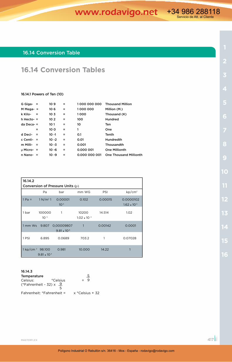
16.14.1 Powers of Ten (10)
G Giga- = 10 9 = 1 000 000 000 Thousand Million
M Mega- = 10 6 = 1 000 000 Million (M.)
k Kilo- = 10 3 = 1 000 Thousand (K)
h Hecto- = 10 2 = 100 Hundred
da Deca- = 10 1 = 10 Ten
= 10 0 = 1 One
d Deci- = 10 -1 = 0.1 Tenth
c Centi- = 10 -2 = 0.01 Hundredth
m Milli- = 10 -3 = 0.001 Thousandth
µ Micro- = 10 -6 = 0.000 001 One Millionth
n Nano- = 10 -9 = 0.000 000 001 One Thousand Millionth
16.14.2Conversion of Pressure Units (
Pa bar mm WG PSI kp/cm2
1 Pa = 1 N/m2 1 0.00001 0.102 0.00015 0.0000102
10-5 1.62 10-5
1 bar 100000 1 10200 14.514 1.02
10 5 1.02 10 4
1 mm Ws 9.807 0,00009807 1 0.00142 0.0001
9.81 10-5
1 PSI 6.895 0.0689 703.2 1 0.07028
1 kp/cm 2 98.100 0.981 10.000 14.22 1
9.81 10 4
16.14.3TemperatureCelsius: °Celsius = (°Fahrenheit - 32) x
Fahrenheit: °Fahrenheit = x °Celsius + 32
95
59
16
15
14
13
12
11
10
9
8
7
6
5
4
3
2
1
417
Polígono Industrial O Rebullón s/n. 36416 - Mos - España - [email protected]
Servicio de Att. al Cliente+34 986 288118
Polígono Industrial O Rebullón s/n. 36416 - Mos - España - [email protected]
Servicio de Att. al Cliente+34 986 288118
Technical Appendix
16.14 Conversion Tables
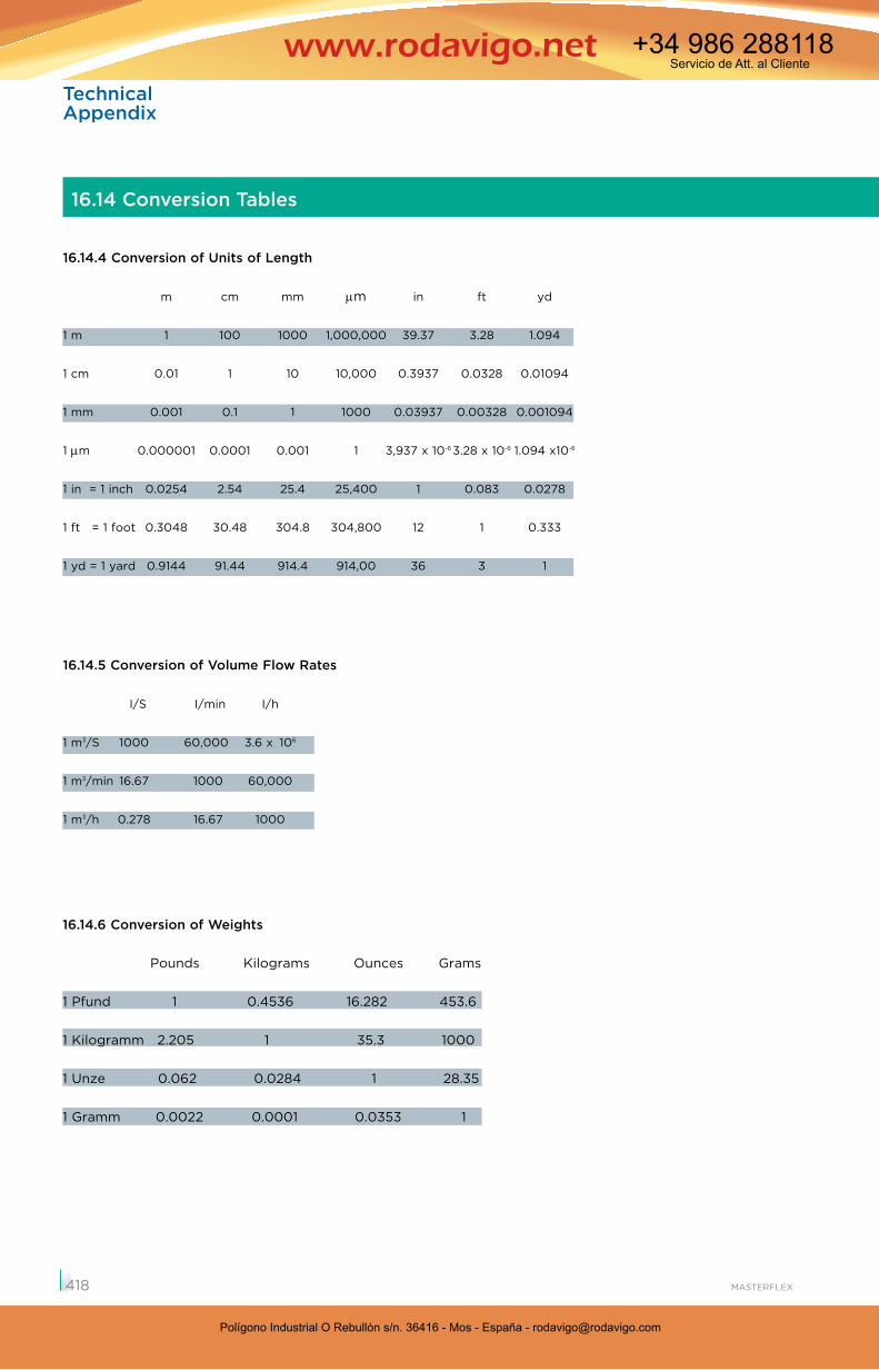
16.14.4 Conversion of Units of Length
m cm mm m in ft yd
1 m 1 100 1000 1,000,000 39.37 3.28 1.094
1 cm 0.01 1 10 10,000 0.3937 0.0328 0.01094
1 mm 0.001 0.1 1 1000 0.03937 0.00328 0.001094
1 m 0.000001 0.0001 0.001 1 3,937 x 10-6 3.28 x 10⁻⁶ 1.094 x10⁻⁶
1 in = 1 inch 0.0254 2.54 25.4 25,400 1 0.083 0.0278
1 ft = 1 foot 0.3048 30.48 304.8 304,800 12 1 0.333
1 yd = 1 yard 0.9144 91.44 914.4 914,00 36 3 1
16.14.5 Conversion of Volume Flow Rates
I/S I/min I/h
1 m3/S 1000 60,000 3.6 x 10⁶
1 m3/min 16.67 1000 60,000
1 m3/h 0.278 16.67 1000
16.14.6 Conversion of Weights
Pounds Kilograms Ounces Grams
1 Pfund 1 0.4536 16.282 453.6
1 Kilogramm 2.205 1 35.3 1000
1 Unze 0.062 0.0284 1 28.35
1 Gramm 0.0022 0.0001 0.0353 1
418
Polígono Industrial O Rebullón s/n. 36416 - Mos - España - [email protected]
Servicio de Att. al Cliente+34 986 288118
Polígono Industrial O Rebullón s/n. 36416 - Mos - España - [email protected]
Servicio de Att. al Cliente+34 986 288118
16.15 CE Accreditation of Masterflex Products
The CE accreditation (Conformité Européenne)
stands for “compliance with EU directives” and is a
EU product safety marking for certain products.
By affixing the CE mark, manufacturers attest the
conformity with one or several EU directives appli-
cable to the respective product. This marking has
meanwhile become mandatory for certain product
groups. There are no trade restrictions for CE marked
products within the EU member states whereas
products without the CE mark, which are subject to
marking, may not be placed on the market from a
specific date onwards (e.g. machinery requires
marking since 1st January 1995).
Masterflex hoses are not included in those product
groups subject to mandatory marking. This is due to
the fact that, as per EC Machinery Directive 89/392/
EEC, hoses are neither considered machinery, safety
components nor products regulated under the low-
voltage or EMC directives, medical products directive
etc. Hoses are components that may not bear the CE
mark.
As a consequence, the CE mark may not be affixed
to hoses and the Masterflex SE is not allowed to issue
declarations of conformity (manufacturer’s declara-
tions).
If requested, it is possible though to provide data
safety sheets acc. to DIN EN 292 and works certifi-
cates acc. to EN 10204 that attest the characteristics
of Masterflex products. Masterflex SE is certified in
accordance with DIN EN ISO 9001. We assure the
high quality of our products.
The data provided by Masterflex is considered
general information. Since individual applications,
local conditions and hose designs differ, no liability or
guarantee can be derived from the given information.
16.15 CE Accreditation of Masterflex Products
16
15
14
13
12
11
10
9
8
7
6
5
4
3
2
1
419
Polígono Industrial O Rebullón s/n. 36416 - Mos - España - [email protected]
Servicio de Att. al Cliente+34 986 288118