Servi manualKM-2810ENSMR3
202
SERVICE MANUAL Published in October 2009 2H9SM063 Rev.3 KM-2810
-
Upload
jsanchez1980 -
Category
Documents
-
view
222 -
download
0
Transcript of Servi manualKM-2810ENSMR3

8/3/2019 Servi manualKM-2810ENSMR3
http://slidepdf.com/reader/full/servi-manualkm-2810ensmr3 1/202
SERVICEMANUAL
Published in October 20092H9SM063
Rev.3
KM-2810

8/3/2019 Servi manualKM-2810ENSMR3
http://slidepdf.com/reader/full/servi-manualkm-2810ensmr3 2/202
CAUTION
RISK OF EXPLOSION IF BATTERY IS REPLACED BY AN INCORRECT TYPE. DISPOSE OFUSED BATTERIES ACCORDING TO THE INSTRUCTIONS.
It may be illegal to dispose of this battery into the municipal waste stream. Check with your localsolid waste officials for details in your area for proper disposal.
ATTENTION
IL Y A UN RISQUE D’EXPLOSION SI LA BATTERIE EST REMPLACEE PAR UN MODELE DETYPE INCORRECT. METTRE AU REBUT LES BATTERIES UTILISEES SELON LES INSTRUC-TIONS DONNEES.
Il peut être illégal de jeter les batteries dans des eaux d’égout municipales. Vérifiez avec les fonc-tionnaires municipaux de votre région pour les détails concernant des déchets solides et une miseau rebut appropriée.

8/3/2019 Servi manualKM-2810ENSMR3
http://slidepdf.com/reader/full/servi-manualkm-2810ensmr3 3/202
Revision history
Revision Date Replaced pages Remarks
1 June 24, 2009 1-1-1, 1-1-3, 1-1-4, 1-2-2, 1-3-1 to 1-3-64, 1-4-3,
1-4-5, 1-4-6, 1-4-7, 1-4-9, 1-5-3, 1-5-12, 1-5-21,
1-5-29, 1-5-30, 1-5-22, 1-5-23, 1-5-24, 1-5-25,
1-5-26, 1-5-27, 1-5-29, 1-5-30, 1-5-49, 2-1-8, 2-2-2,
2-2-4, 2-3-2, 2-4-2, 2-4-4
-
2 August 11, 2009 1-3-3 to 1-3-7, 1-3-13, 1-3-14, 1-3-28 to 1-3-31,
1-3-33, 1-3-39, 1-3-48, 1-5-2, 1-5-29, 1-5-30
-

8/3/2019 Servi manualKM-2810ENSMR3
http://slidepdf.com/reader/full/servi-manualkm-2810ensmr3 4/202
This page is intentionally left blank.

8/3/2019 Servi manualKM-2810ENSMR3
http://slidepdf.com/reader/full/servi-manualkm-2810ensmr3 5/202
Safety precautions
This booklet provides safety warnings and precautions for our service personnel to ensure the safety oftheir customers, their machines as well as themselves during maintenance activities. Service personnelare advised to read this booklet carefully to familiarize themselves with the warnings and precautions
described here before engaging in maintenance activities.
8/3/2019 Servi manualKM-2810ENSMR3
http://slidepdf.com/reader/full/servi-manualkm-2810ensmr3 6/202
Safety warnings and precautions
Various symbols are used to protect our service personnel and customers from physical danger andto prevent damage to their property. These symbols are described below:
DANGER: High risk of serious bodily injury or death may result from insufficient attention to or incorrect
compliance with warning messages using this symbol.
WARNING: Serious bodily injury or death may result from insufficient attention to or incorrect compliance
with warning messages using this symbol.
CAUTION: Bodily injury or damage to property may result from insufficient attention to or incorrect
compliance with warning messages using this symbol.
Symbols
The triangle ( ) symbol indicates a warning including danger and caution. The specific point
of attention is shown inside the symbol.
General warning.
Warning of risk of electric shock.
Warning of high temperature.
indicates a prohibited action. The specific prohibition is shown inside the symbol.
General prohibited action.
Disassembly prohibited.
indicates that action is required. The specific action required is shown inside the symbol.
General action required.
Remove the power plug from the wall outlet.
Always ground the copier.
8/3/2019 Servi manualKM-2810ENSMR3
http://slidepdf.com/reader/full/servi-manualkm-2810ensmr3 7/202
1.Installation Precautions
WARNING
• Do not use a power supply with a voltage other than that specified. Avoid multiple connections to
one outlet: they may cause fire or electric shock. When using an extension cable, always checkthat it is adequate for the rated current. .............................................................................................
• Connect the ground wire to a suitable grounding point. Not grounding the copier may cause fire orelectric shock. Connecting the earth wire to an object not approved for the purpose may causeexplosion or electric shock. Never connect the ground cable to any of the following: gas pipes,lightning rods, ground cables for telephone lines and water pipes or faucets not approved by theproper authorities. ............................................................................................................................
CAUTION:
• Do not place the copier on an infirm or angled surface: the copier may tip over, causing injury. .......
• Do not install the copier in a humid or dusty place. This may cause fire or electric shock. ................
• Do not install the copier near a radiator, heater, other heat source or near flammable material.
This may cause fire. .........................................................................................................................
• Allow sufficient space around the copier to allow the ventilation grills to keep the machine as coolas possible. Insufficient ventilation may cause heat buildup and poor copying performance. ...........
• Always handle the machine by the correct locations when moving it. ...............................................
• Always use anti-toppling and locking devices on copiers so equipped. Failure to do this may causethe copier to move unexpectedly or topple, leading to injury. ...........................................................
• Avoid inhaling toner or developer excessively. Protect the eyes. If toner or developer is acciden-tally ingested, drink a lot of water to dilute it in the stomach and obtain medical attention immedi-ately. If it gets into the eyes, rinse immediately with copious amounts of water and obtain medicalattention. ......................................................................................................................................
• Advice customers that they must always follow the safety warnings and precautions in the copier’sinstruction handbook. .....................................................................................................................
8/3/2019 Servi manualKM-2810ENSMR3
http://slidepdf.com/reader/full/servi-manualkm-2810ensmr3 8/202
2.Precautions for Maintenance
WARNING
• Always remove the power plug from the wall outlet before starting machine disassembly. ...............
• Always follow the procedures for maintenance described in the service manual and other relatedbrochures. .......................................................................................................................................
• Under no circumstances attempt to bypass or disable safety features including safety mechanismsand protective circuits. .....................................................................................................................
• Always use parts having the correct specifications. ..........................................................................
• Always use the thermostat or thermal fuse specified in the service manual or other related bro-chure when replacing them. Using a piece of wire, for example, could lead to fire or other seriousaccident. ..........................................................................................................................................
• When the service manual or other serious brochure specifies a distance or gap for installation of apart, always use the correct scale and measure carefully. ................................................................
• Always check that the copier is correctly connected to an outlet with a ground connection. .............
• Check that the power cable covering is free of damage. Check that the power plug is dust-free. If itis dirty, clean it to remove the risk of fire or electric shock. ..............................................................
• Never attempt to disassemble the optical unit in machines using lasers. Leaking laser light maydamage eyesight. ...........................................................................................................................
• Handle the charger sections with care. They are charged to high potentials and may cause electricshock if handled improperly. ............................................................................................................
CAUTION
• Wear safe clothing. If wearing loose clothing or accessories such as ties, make sure they are
safely secured so they will not be caught in rotating sections. ..........................................................
• Use utmost caution when working on a powered machine. Keep away from chains and belts. ........
• Handle the fixing section with care to avoid burns as it can be extremely hot. ..................................
• Check that the fixing unit thermistor, heat and press rollers are clean. Dirt on them can causeabnormally high temperatures. ........................................................................................................
8/3/2019 Servi manualKM-2810ENSMR3
http://slidepdf.com/reader/full/servi-manualkm-2810ensmr3 9/202
• Do not remove the ozone filter, if any, from the copier except for routine replacement. ....................
• Do not pull on the AC power cord or connector wires on high-voltage components when removingthem; always hold the plug itself. .....................................................................................................
• Do not route the power cable where it may be stood on or trapped. If necessary, protect it with acable cover or other appropriate item. .............................................................................................
• Treat the ends of the wire carefully when installing a new charger wire to avoid electric leaks. ........
• Remove toner completely from electronic components. ...................................................................
• Run wire harnesses carefully so that wires will not be trapped or damaged. ....................................
• After maintenance, always check that all the parts, screws, connectors and wires that wereremoved, have been refitted correctly. Special attention should be paid to any forgotten connector,trapped wire and missing screws. ...................................................................................................
• Check that all the caution labels that should be present on the machine according to the instructionhandbook are clean and not peeling. Replace with new ones if necessary. ......................................
• Handle greases and solvents with care by following the instructions below: .....................................
Use only a small amount of solvent at a time, being careful not to spill. Wipe spills off completely.Ventilate the room well while using grease or solvents.Allow applied solvents to evaporate completely before refitting the covers or turning the power switch on.Always wash hands afterwards.
• Never dispose of toner or toner bottles in fire. Toner may cause sparks when exposed directly tofire in a furnace, etc. .......................................................................................................................
• Should smoke be seen coming from the copier, remove the power plug from the wall outlet imme-diately. ............................................................................................................................................
3.Miscellaneous
WARNING
• Never attempt to heat the drum or expose it to any organic solvents such as alcohol, other than thespecified refiner; it may generate toxic gas. .....................................................................................

8/3/2019 Servi manualKM-2810ENSMR3
http://slidepdf.com/reader/full/servi-manualkm-2810ensmr3 10/202
This page is intentionally left blank.
8/3/2019 Servi manualKM-2810ENSMR3
http://slidepdf.com/reader/full/servi-manualkm-2810ensmr3 11/202
CONTENTS
1-1 Specifications1-1-1 Specifications..........................................................................................................................................1-1-1
1-1-2 Parts names............................................................................................................................................1-1-3
(1) Overall ...............................................................................................................................................1-1-3
(2) Operation panel.................................................................................................................................1-1-4
1-1-3 Machine cross section ............................................................................................................................1-1-5
1-2 Installation1-2-1 Installation environment ..........................................................................................................................1-2-1
1-2-2 Unpacking ...............................................................................................................................................1-2-2
(1) Unpacking .........................................................................................................................................1-2-2
(2) Removing the tapes ..........................................................................................................................1-2-3
1-2-3 Installing the expansion memory (option) ...............................................................................................1-2-5
1-3 Maintenance Mode1-3-1 Maintenance mode .................................................................................................................................1-3-1
(1) Executing a maintenance item ..........................................................................................................1-3-1
(2) Maintenance modes item list.............................................................................................................1-3-2
(3) Contents of the maintenance mode items.........................................................................................1-3-4
1-3-2 Management mode ...............................................................................................................................1-3-52
(1) Using the management mode .........................................................................................................1-3-52
(2) Common Settings............................................................................................................................1-3-53
(3) Copy Settings..................................................................................................................................1-3-57
(4) Sending Settings .............................................................................................................................1-3-57
(5) Document Box Settings...................................................................................................................1-3-57
(6) Printer Settings................................................................................................................................1-3-58
(7) Printing Reports/Sending Notice .....................................................................................................1-3-58
(8) Adjustment/Maintenance.................................................................................................................1-3-59
(9) Date/Timer.......................................................................................................................................1-3-59
(10) Editing Destination (Address Book/Adding One-Touch Keys) ........................................................1-3-60
(11) Restarting the System.....................................................................................................................1-3-61
(12) Network Setup.................................................................................................................................1-3-61
(13) User Login Administration ...............................................................................................................1-3-63(14) Job accounting ................................................................................................................................1-3-63
1-4 Troubleshooting1-4-1 Paper misfeed detection .........................................................................................................................1-4-1
(1) Paper misfeed indication...................................................................................................................1-4-1
(2) Paper misfeed detection condition ....................................................................................................1-4-1
1-4-2 Self-diagnostic function...........................................................................................................................1-4-2
(1) Self-diagnostic function .....................................................................................................................1-4-2
(2) Self diagnostic codes ........................................................................................................................1-4-3
1-4-3 Image formation problems ....................................................................................................................1-4-10
(1) Completely blank printout................................................................................................................1-4-11
(2) All-black printout..............................................................................................................................1-4-11
(3) Dropouts..........................................................................................................................................1-4-12(4) Black dots........................................................................................................................................1-4-12
(5) Black horizontal streaks. .................................................................................................................1-4-12
(6) Black vertical streaks.......................................................................................................................1-4-13
(7) Unsharpness. ..................................................................................................................................1-4-13
(8) Gray background.............................................................................................................................1-4-13
(9) Dirt on the top edge or back of the paper........................................................................................1-4-14
(10) Undulated printing at the right edge (scanning start position). ........................................................1-4-14
1-4-4 Electric problems ..................................................................................................................................1-4-15
1-4-5 Mechanical problems ............................................................................................................................1-4-18
1-5 Assembly and Disassembly1-5-1 Precautions for assembly and disassembly............................................................................................1-5-1
(1) Precautions .......................................................................................................................................1-5-1
(2) Drum..................................................................................................................................................1-5-1
(3) Toner.................................................................................................................................................1-5-1
(4) How to tell a genuine Kyocera Mita toner container..........................................................................1-5-2
8/3/2019 Servi manualKM-2810ENSMR3
http://slidepdf.com/reader/full/servi-manualkm-2810ensmr3 12/202
1-5-2 Outer covers ...........................................................................................................................................1-5-3
(1) Detaching and refitting the left cover and right cover........................................................................1-5-3
1-5-3 Paper feed section ..................................................................................................................................1-5-6
(1) Detaching and refitting the paper feed assembly (paper feed roller and pickup roller) .....................1-5-6
(2) Detaching and refitting the retard roller assembly.............................................................................1-5-8
(3) Detaching and refitting the MP paper feed roller.............................................................................1-5-10
(4) Note on removing and Installing the upper registration roller and lower registration roller .............1-5-12
1-5-4 Optical section ......................................................................................................................................1-5-13
(1) Detaching and refitting the original cover........................................................................................1-5-13(2) Detaching and refitting the scanner unit (LSU) ...............................................................................1-5-14
(3) Detaching and refitting the laser scanner unit (LSU).......................................................................1-5-17
(4) Replacing the image scanner unit (ISU)..........................................................................................1-5-21
(5) Detaching and refitting the exposure lamp and inverter PWB.........................................................1-5-27
1-5-5 Developing section................................................................................................................................1-5-29
(1) Detaching and refitting the developing unit .....................................................................................1-5-29
1-5-6 Drum section.........................................................................................................................................1-5-30
(1) Detaching and refitting the drum unit ..............................................................................................1-5-30
(2) Detaching and refitting the main charger unit..................................................................................1-5-31
1-5-7 Transfer/separation section ..................................................................................................................1-5-32
(1) Detaching and refitting the transfer roller........................................................................................1-5-32
1-5-8 Fuser section ........................................................................................................................................1-5-34
(1) Detaching and refitting the fuser unit...............................................................................................1-5-34
(2) Switching the fuser pressure...........................................................................................................1-5-38
1-5-9 PWBs....................................................................................................................................................1-5-39
(1) Detaching and refitting the control PWB .........................................................................................1-5-39
(2) Detaching and refitting the power source PWB...............................................................................1-5-42
(3) Detaching and refitting the high voltage PWB.................................................................................1-5-45
(4) Detaching and refitting the scanner PWB .......................................................................................1-5-49
1-5-10 Others ...................................................................................................................................................1-5-50
(1) Detaching and refitting the main motor ...........................................................................................1-5-50
(2) Direction of installing the left cooling fan motor, right cooling fan motor and power
source fan motor .............................................................................................................................1-5-51
1-6 Requirements on PWB Replacement1-6-1 Firmware.................................................................................................................................................1-6-1
(1) Upgrading the firmware.....................................................................................................................1-6-11-6-2 Remarks on control PWB replacement...................................................................................................1-6-2
2-1 Mechanical Construction2-1-1 Paper feed/conveying section.................................................................................................................2-1-1
(1) Cassette paper feed section..............................................................................................................2-1-1
(2) MP tray paper feed section ...............................................................................................................2-1-2
(3) Paper conveying section ...................................................................................................................2-1-3
2-1-2 Drum section...........................................................................................................................................2-1-4
(1) Drum section .....................................................................................................................................2-1-4
(2) Main charger unit...............................................................................................................................2-1-5
2-1-3 Optical section ........................................................................................................................................2-1-6
(1) Scanner unit ......................................................................................................................................2-1-6
(2) Image scanner unit (ISU) ..................................................................................................................2-1-7(3) Laser scanner unit (LSU) ..................................................................................................................2-1-9
2-1-4 Developing section................................................................................................................................2-1-11
2-1-5 Transfer/separation section ..................................................................................................................2-1-12
2-1-6 Cleaning section ...................................................................................................................................2-1-13
2-1-7 Fuser section ........................................................................................................................................2-1-14
2-1-8 Paper exit section .................................................................................................................................2-1-16
2-1-9 Duplex/conveying section .....................................................................................................................2-1-18
2-2 Electrical Parts Layout2-2-1 Electrical parts layout..............................................................................................................................2-2-1
(1) PWBs ................................................................................................................................................2-2-1
(2) Switches and sensors .......................................................................................................................2-2-3
(3) Other electrical components..............................................................................................................2-2-4
2-3 Operation of the PWBs2-3-1 Power source PWB.................................................................................................................................2-3-1

8/3/2019 Servi manualKM-2810ENSMR3
http://slidepdf.com/reader/full/servi-manualkm-2810ensmr3 13/202
2-3-2 Control PWB ...........................................................................................................................................2-3-3
2-3-3 Scanner PWB .........................................................................................................................................2-3-9
2-4 Appendixes2-4-1 Appendixes .............................................................................................................................................2-4-1
(1) Wiring diagram ..................................................................................................................................2-4-1
(2) Repetitive defects gauge...................................................................................................................2-4-3
(3) Maintenance parts list .......................................................................................................................2-4-4

8/3/2019 Servi manualKM-2810ENSMR3
http://slidepdf.com/reader/full/servi-manualkm-2810ensmr3 14/202
This page is intentionally left blank.
8/3/2019 Servi manualKM-2810ENSMR3
http://slidepdf.com/reader/full/servi-manualkm-2810ensmr3 15/202
2H9-1
1-1-1
1-1 Specifications
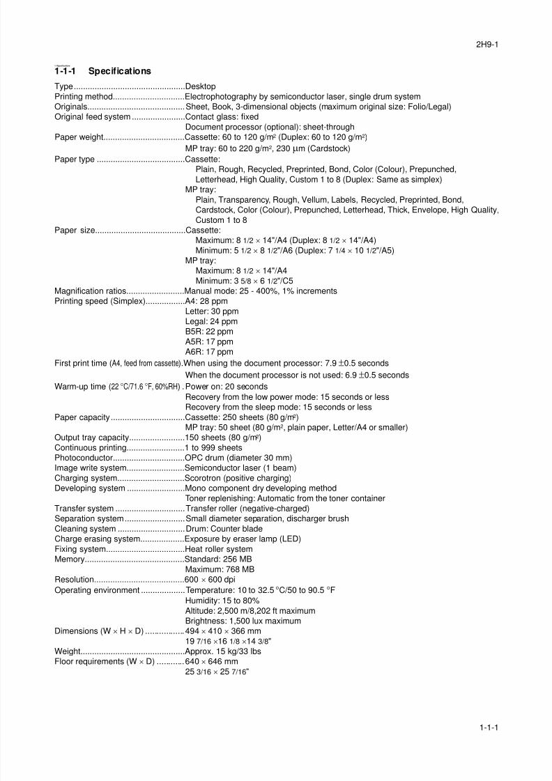
1-1-1 Specifications
Type................................................Desktop
Printing method...............................Electrophotography by semiconductor laser, single drum system
Originals..........................................Sheet, Book, 3-dimensional objects (maximum original size: Folio/Legal)
Original feed system .......................Contact glass: fixed
Document processor (optional): sheet-through
Paper weight...................................Cassette: 60 to 120 g/m2 (Duplex: 60 to 120 g/m2)MP tray: 60 to 220 g/m2, 230 µm (Cardstock)
Paper type ......................................Cassette:
Plain, Rough, Recycled, Preprinted, Bond, Color (Colour), Prepunched,
Letterhead, High Quality, Custom 1 to 8 (Duplex: Same as simplex)
MP tray:
Plain, Transparency, Rough, Vellum, Labels, Recycled, Preprinted, Bond,
Cardstock, Color (Colour), Prepunched, Letterhead, Thick, Envelope, High Quality,
Custom 1 to 8
Paper size.......................................Cassette:
Maximum: 8 1/2 × 14"/A4 (Duplex: 8 1/2 × 14"/A4)
Minimum: 5 1/2 × 8 1/2"/A6 (Duplex: 7 1/4 × 10 1/2"/A5)
MP tray:
Maximum: 8 1/2 × 14"/A4Minimum: 3 5/8 × 6 1/2"/C5
Magnification ratios.........................Manual mode: 25 - 400%, 1% increments
Printing speed (Simplex).................A4: 28 ppm
Letter: 30 ppm
Legal: 24 ppm
B5R: 22 ppm
A5R: 17 ppm
A6R: 17 ppm
First print time (A4, feed from cassette).When using the document processor: 7.9 ±0.5 seconds
When the document processor is not used: 6.9 ±0.5 seconds
Warm-up time (22 °C/71.6 °F, 60%RH) .Power on: 20 seconds
Recovery from the low power mode: 15 seconds or less
Recovery from the sleep mode: 15 seconds or lessPaper capacity................................Cassette: 250 sheets (80 g/m2)
MP tray: 50 sheet (80 g/m2, plain paper, Letter/A4 or smaller)
Output tray capacity........................150 sheets (80 g/m2)
Continuous printing.........................1 to 999 sheets
Photoconductor...............................OPC drum (diameter 30 mm)
Image write system.........................Semiconductor laser (1 beam)
Charging system.............................Scorotron (positive charging)
Developing system .........................Mono component dry developing method
Toner replenishing: Automatic from the toner container
Transfer system ..............................Transfer roller (negative-charged)
Separation system..........................Small diameter separation, discharger brush
Cleaning system .............................Drum: Counter blade
Charge erasing system...................Exposure by eraser lamp (LED)
Fixing system..................................Heat roller systemMemory...........................................Standard: 256 MB
Maximum: 768 MB
Resolution.......................................600 × 600 dpi
Operating environment ...................Temperature: 10 to 32.5 °C/50 to 90.5 °FHumidity: 15 to 80%
Altitude: 2,500 m/8,202 ft maximum
Brightness: 1,500 lux maximum
Dimensions (W × H × D) .................494 × 410 × 366 mm
19 7/16 ×16 1/8 ×14 3/8"
Weight.............................................Approx. 15 kg/33 lbs
Floor requirements (W × D) ............640 × 646 mm
25 3/16 × 25 7/16"
8/3/2019 Servi manualKM-2810ENSMR3
http://slidepdf.com/reader/full/servi-manualkm-2810ensmr3 16/202
2H9-3
1-1-2
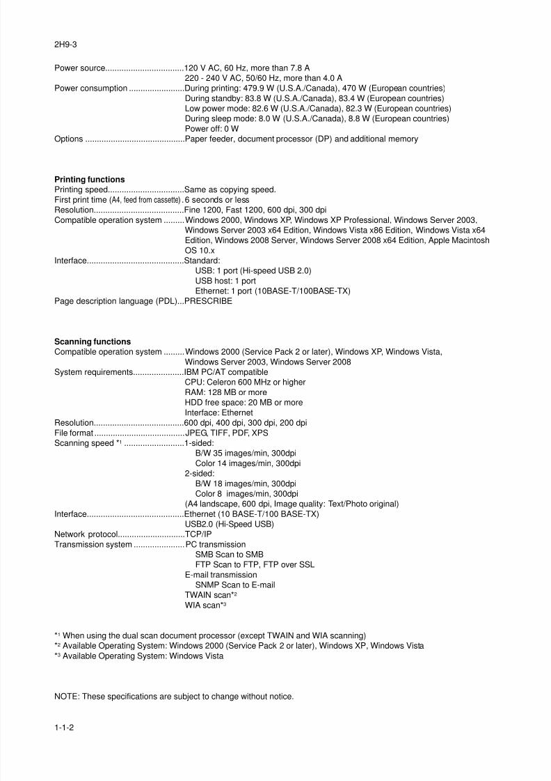
Power source..................................120 V AC, 60 Hz, more than 7.8 A
220 - 240 V AC, 50/60 Hz, more than 4.0 A
Power consumption ........................During printing: 479.9 W (U.S.A./Canada), 470 W (European countries)
During standby: 83.8 W (U.S.A./Canada), 83.4 W (European countries)
Low power mode: 82.6 W (U.S.A./Canada), 82.3 W (European countries)
During sleep mode: 8.0 W (U.S.A./Canada), 8.8 W (European countries)
Power off: 0 W
Options ...........................................Paper feeder, document processor (DP) and additional memory
Printing functions
Printing speed.................................Same as copying speed.
First print time (A4, feed from cassette) .6 seconds or less
Resolution.......................................Fine 1200, Fast 1200, 600 dpi, 300 dpi
Compatible operation system .........Windows 2000, Windows XP, Windows XP Professional, Windows Server 2003,
Windows Server 2003 x64 Edition, Windows Vista x86 Edition, Windows Vista x64
Edition, Windows 2008 Server, Windows Server 2008 x64 Edition, Apple Macintosh
OS 10.x
Interface..........................................Standard:
USB: 1 port (Hi-speed USB 2.0)USB host: 1 port
Ethernet: 1 port (10BASE-T/100BASE-TX)
Page description language (PDL)...PRESCRIBE
Scanning functions
Compatible operation system .........Windows 2000 (Service Pack 2 or later), Windows XP, Windows Vista,
Windows Server 2003, Windows Server 2008
System requirements......................IBM PC/AT compatible
CPU: Celeron 600 MHz or higher
RAM: 128 MB or more
HDD free space: 20 MB or more
Interface: EthernetResolution.......................................600 dpi, 400 dpi, 300 dpi, 200 dpi
File format .......................................JPEG, TIFF, PDF, XPS
Scanning speed *1 ..........................1-sided:
B/W 35 images/min, 300dpi
Color 14 images/min, 300dpi
2-sided:
B/W 18 images/min, 300dpi
Color 8 images/min, 300dpi
(A4 landscape, 600 dpi, Image quality: Text/Photo original)
Interface..........................................Ethernet (10 BASE-T/100 BASE-TX)
USB2.0 (Hi-Speed USB)
Network protocol.............................TCP/IP
Transmission system ......................PC transmissionSMB Scan to SMB
FTP Scan to FTP, FTP over SSL
E-mail transmission
SNMP Scan to E-mail
TWAIN scan*2
WIA scan*3
*1 When using the dual scan document processor (except TWAIN and WIA scanning)
*2 Available Operating System: Windows 2000 (Service Pack 2 or later), Windows XP, Windows Vista
*3 Available Operating System: Windows Vista
NOTE: These specifications are subject to change without notice.
8/3/2019 Servi manualKM-2810ENSMR3
http://slidepdf.com/reader/full/servi-manualkm-2810ensmr3 17/202
2H9-1
1-1-3
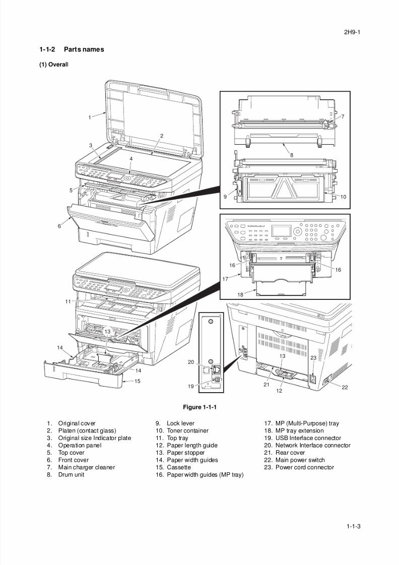
1-1-2 Parts names
(1) Overall
Figure 1-1-1
1 7
9
8
2
3
5
6
10
11
13
13
12
14
14
18
19 21
23
22
20
17
1616
15
4
1. Original cover
2. Platen (contact glass)
3. Original size Indicator plate
4. Operation panel
5. Top cover
6. Front cover
7. Main charger cleaner
8. Drum unit
9. Lock lever
10. Toner container
11. Top tray
12. Paper length guide
13. Paper stopper
14. Paper width guides
15. Cassette
16. Paper width guides (MP tray)
17. MP (Multi-Purpose) tray
18. MP tray extension
19. USB Interface connector
20. Network Interface connector
21. Rear cover
22. Main power switch
23. Power cord connector
8/3/2019 Servi manualKM-2810ENSMR3
http://slidepdf.com/reader/full/servi-manualkm-2810ensmr3 18/202
2H9-1
1-1-4
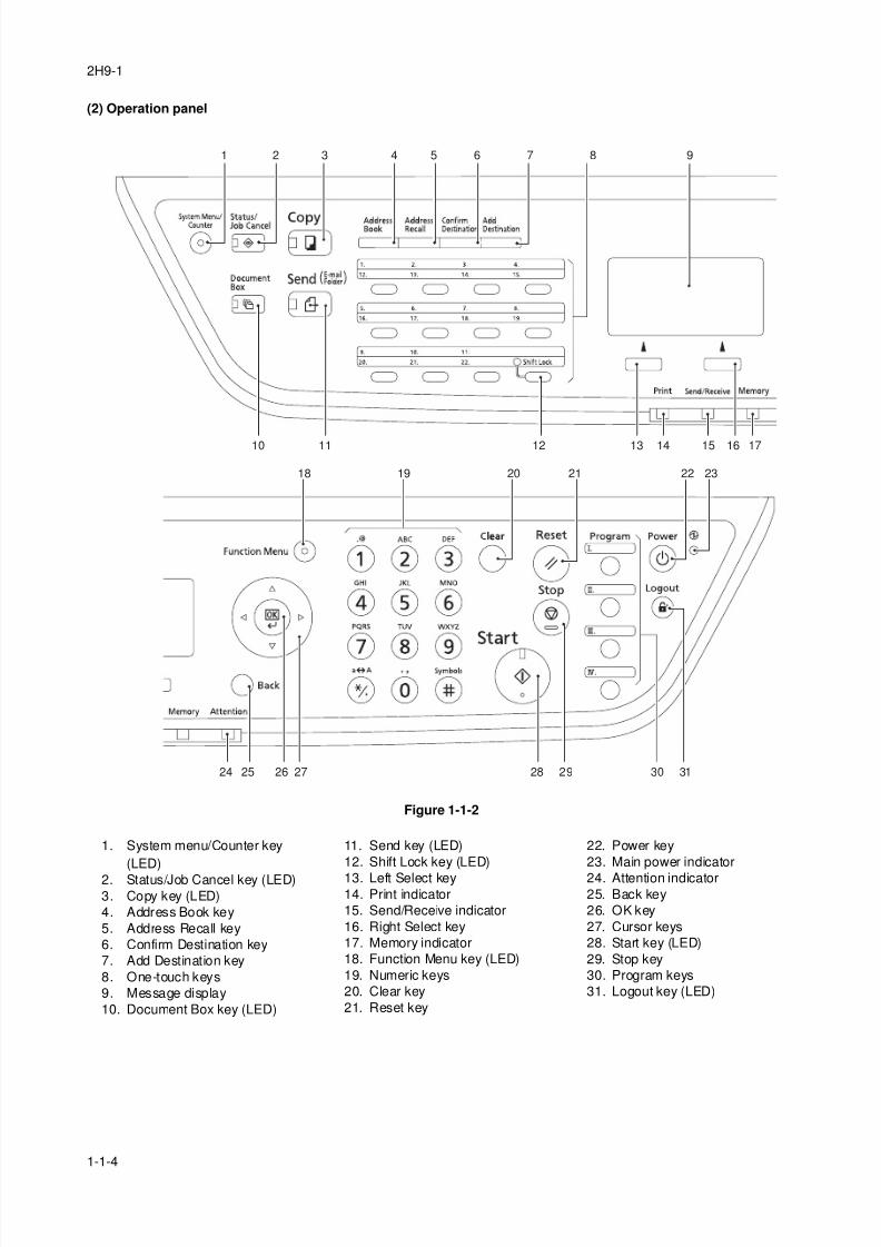
(2) Operation panel
Figure 1-1-2
1
10 11 13 14 15 16 1712
18 19 20 21 22 23
28 29 30 3127262524
32 4 5 6 7 8 9
1. System menu/Counter key
(LED)
2. Status/Job Cancel key (LED)
3. Copy key (LED)
4. Address Book key
5. Address Recall key
6. Confirm Destination key
7. Add Destination key
8. One-touch keys
9. Message display
10. Document Box key (LED)
11. Send key (LED)
12. Shift Lock key (LED)
13. Left Select key14. Print indicator
15. Send/Receive indicator
16. Right Select key
17. Memory indicator
18. Function Menu key (LED)
19. Numeric keys
20. Clear key
21. Reset key
22. Power key
23. Main power indicator
24. Attention indicator25. Back key
26. OK key
27. Cursor keys
28. Start key (LED)
29. Stop key
30. Program keys
31. Logout key (LED)
8/3/2019 Servi manualKM-2810ENSMR3
http://slidepdf.com/reader/full/servi-manualkm-2810ensmr3 19/202
2H9
1-1-5
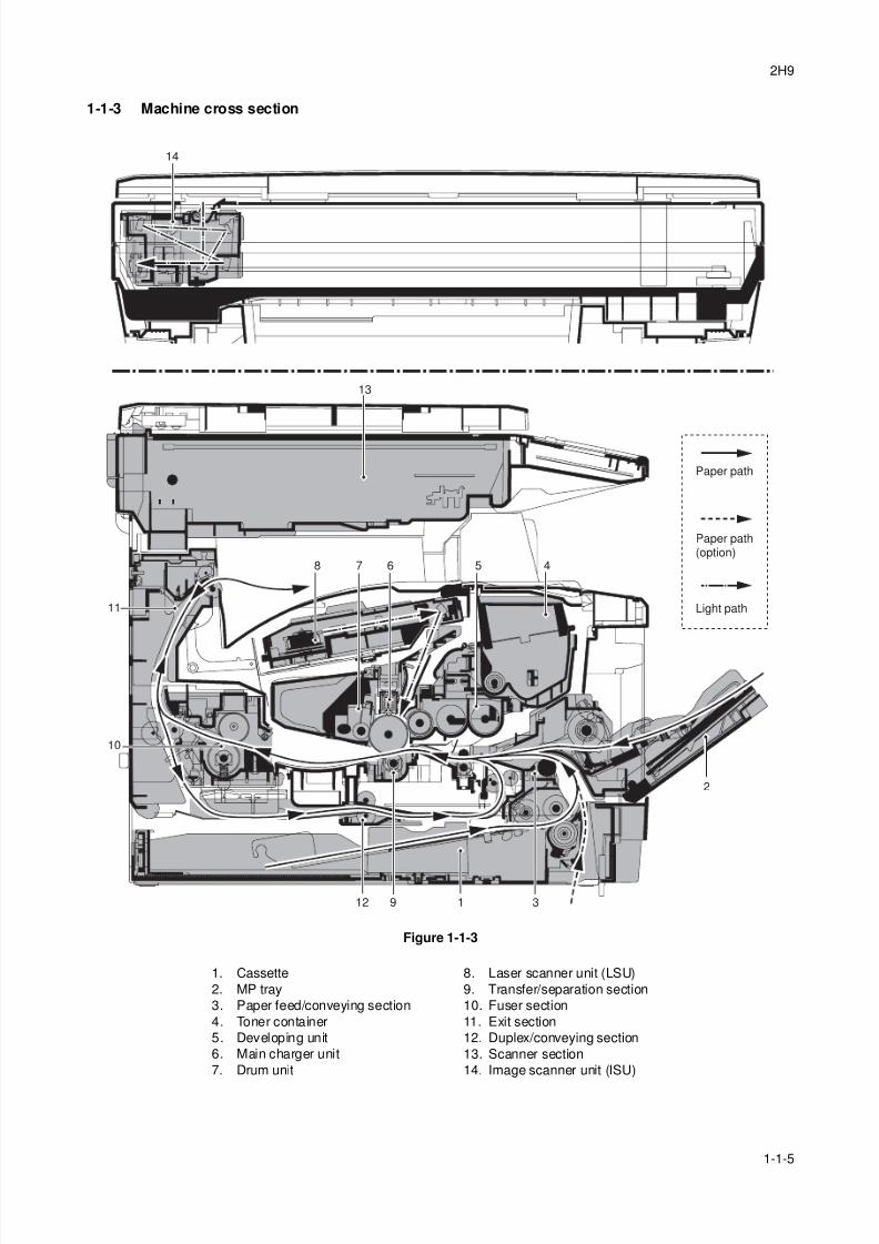
1-1-3 Machine cross section
Figure 1-1-3
13
14
1912 3
2
45678
10
11
Paper path
Paper path(option)
Light path
1. Cassette
2. MP tray
3. Paper feed/conveying section
4. Toner container
5. Developing unit
6. Main charger unit
7. Drum unit
8. Laser scanner unit (LSU)
9. Transfer/separation section
10. Fuser section
11. Exit section
12. Duplex/conveying section
13. Scanner section
14. Image scanner unit (ISU)

8/3/2019 Servi manualKM-2810ENSMR3
http://slidepdf.com/reader/full/servi-manualkm-2810ensmr3 20/202
2H9
1-1-6
This page is intentionally left blank.
8/3/2019 Servi manualKM-2810ENSMR3
http://slidepdf.com/reader/full/servi-manualkm-2810ensmr3 21/202
2H9
1-2-1
1-2 Installation
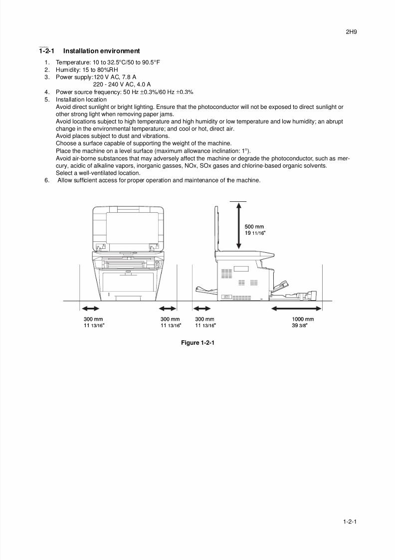
1-2-1 Installation environment
1. Temperature: 10 to 32.5°C/50 to 90.5°F2. Humidity: 15 to 80%RH
3. Power supply:120 V AC, 7.8 A
220 - 240 V AC, 4.0 A
4. Power source frequency: 50 Hz ±0.3%/60 Hz ±0.3%
5. Installation locationAvoid direct sunlight or bright lighting. Ensure that the photoconductor will not be exposed to direct sunlight or
other strong light when removing paper jams.
Avoid locations subject to high temperature and high humidity or low temperature and low humidity; an abrupt
change in the environmental temperature; and cool or hot, direct air.
Avoid places subject to dust and vibrations.
Choose a surface capable of supporting the weight of the machine.
Place the machine on a level surface (maximum allowance inclination: 1°).Avoid air-borne substances that may adversely affect the machine or degrade the photoconductor, such as mer-
cury, acidic of alkaline vapors, inorganic gasses, NOx, SOx gases and chlorine-based organic solvents.
Select a well-ventilated location.
6. Allow sufficient access for proper operation and maintenance of the machine.
Figure 1-2-1
300 mm11 13/16"300 mm11 13/16"
300 mm11 13/16"300 mm11 13/16"
300 mm11 13/16"300 mm11 13/16"
500 mm19 11/16"500 mm19 11/16"
1000 mm39 3/8"1000 mm39 3/8"
8/3/2019 Servi manualKM-2810ENSMR3
http://slidepdf.com/reader/full/servi-manualkm-2810ensmr3 22/202
2H9-1
1-2-2
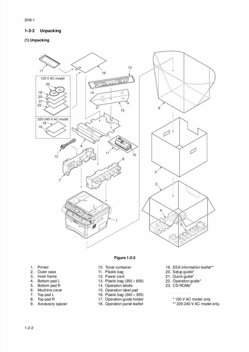
1-2-2 Unpacking
(1) Unpacking
Figure 1-2-2
4
2
15
3
6
8
1011
12
13
14
1617
18
1819
20
2122
23
15
7
9
120 V AC model
220-240 V AC model
1. Printer
2. Outer case
3. Inner frame
4. Bottom pad L
5. Bottom pad R
6. Machine cover
7. Top pad L
8. Top pad R
9. Accessory spacer
10. Toner container
11. Plastic bag
12. Power cord
13. Plastic bag (250 × 600)
14. Operation labels
15. Operation label pad
16. Plastic bag (240 × 350)
17. Operation guide holder
18. Operation panel leaflet
19. EEA information leaflet**
20. Setup guide*
21. Quick guide*
22. Operation guide*
23. CD-ROMs*
* 120 V AC model only.
** 220-240 V AC model only.
8/3/2019 Servi manualKM-2810ENSMR3
http://slidepdf.com/reader/full/servi-manualkm-2810ensmr3 23/202
2H9
1-2-3
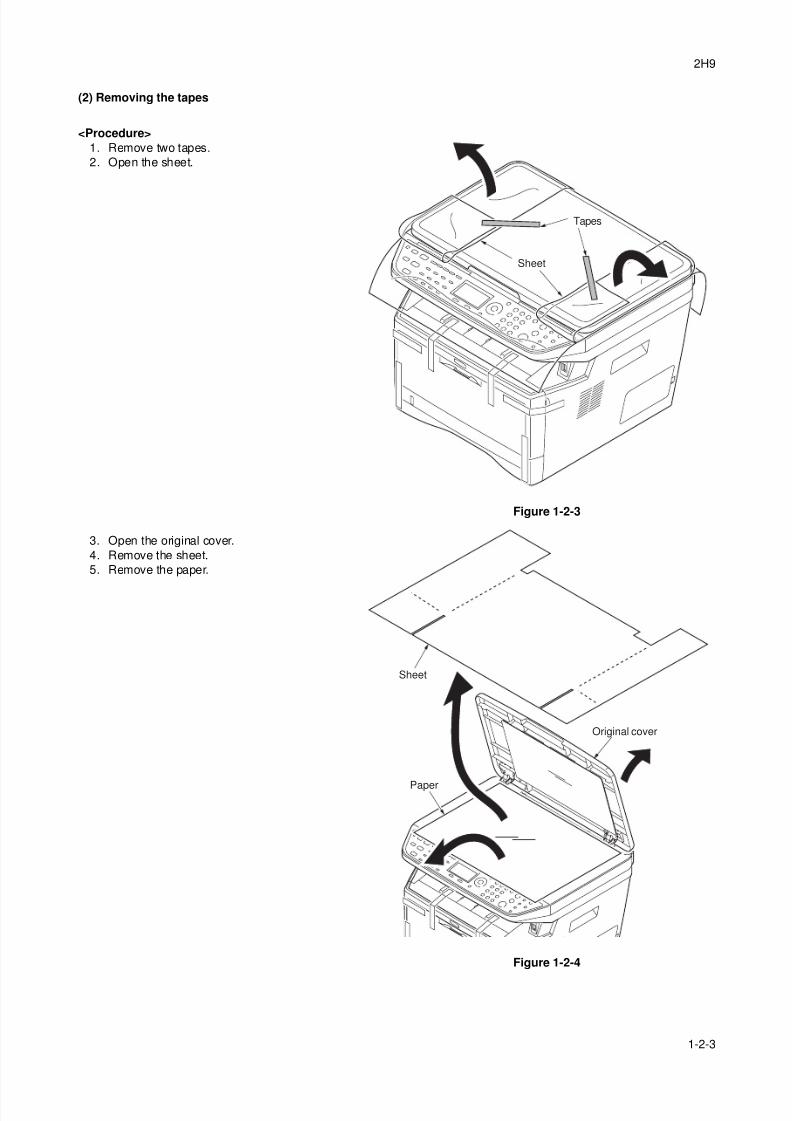
(2) Removing the tapes
<Procedure>
1. Remove two tapes.
2. Open the sheet.
Figure 1-2-3
3. Open the original cover.
4. Remove the sheet.
5. Remove the paper.
Figure 1-2-4
Tapes
Sheet
Original cover
Sheet
Paper
8/3/2019 Servi manualKM-2810ENSMR3
http://slidepdf.com/reader/full/servi-manualkm-2810ensmr3 24/202
2H9
1-2-4
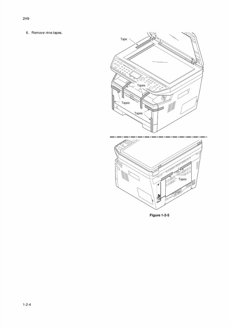
6. Remove nine tapes.
Figure 1-2-5
Tape
Tapes
Tapes
Tapes
Tapes
8/3/2019 Servi manualKM-2810ENSMR3
http://slidepdf.com/reader/full/servi-manualkm-2810ensmr3 25/202
2H9
1-2-5
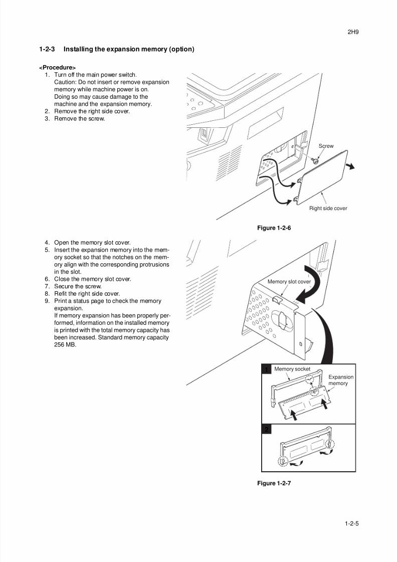
1-2-3 Installing the expansion memory (option)
<Procedure>
1. Turn off the main power switch.
Caution: Do not insert or remove expansion
memory while machine power is on.
Doing so may cause damage to themachine and the expansion memory.
2. Remove the right side cover.
3. Remove the screw.
Figure 1-2-6
4. Open the memory slot cover.
5. Insert the expansion memory into the mem-
ory socket so that the notches on the mem-
ory align with the corresponding protrusions
in the slot.
6. Close the memory slot cover.
7. Secure the screw.
8. Refit the right side cover.9. Print a status page to check the memory
expansion.
If memory expansion has been properly per-
formed, information on the installed memory
is printed with the total memory capacity has
been increased. Standard memory capacity
256 MB.
Figure 1-2-7
Right side cover
Screw
1
2
Expansionmemory
Memory socket
Memory slot cover

8/3/2019 Servi manualKM-2810ENSMR3
http://slidepdf.com/reader/full/servi-manualkm-2810ensmr3 26/202
2H9
1-2-6
This page is intentionally left blank.
8/3/2019 Servi manualKM-2810ENSMR3
http://slidepdf.com/reader/full/servi-manualkm-2810ensmr3 27/202
2H9-1
1-3-1
1-3 Maintenance Mode
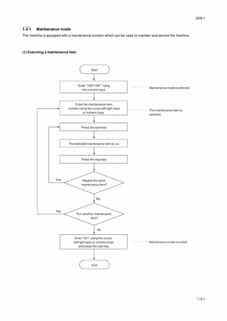
1-3-1 Maintenance mode
The machine is equipped with a maintenance function which can be used to maintain and service the machine.
(1) Executing a maintenance item
Enter “10871087” using
the numeric keys.
Enter “001” using the cursor
left/right keys or numeric keys
and press the start key.
Enter the maintenance item
number using the cursor left/right keys
or numeric keys.
The selected maintenance item is run.
Press the stop key.
Press the start key.
Start
End
Maintenance mode is entered.
The maintenance item is
selected.
Maintenance mode is exited.
Repeat the same
maintenance item?
Run another maintenance
item?
No
No
Yes
Yes
8/3/2019 Servi manualKM-2810ENSMR3
http://slidepdf.com/reader/full/servi-manualkm-2810ensmr3 28/202
2H9-1
1-3-2
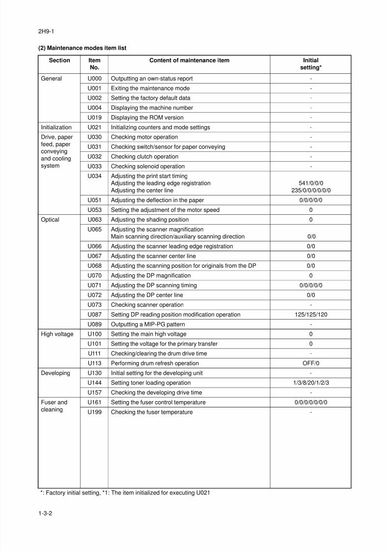
(2) Maintenance modes item list
Section Item
No.
Content of maintenance item Initial
setting*
General U000 Outputting an own-status report -
U001 Exiting the maintenance mode -
U002 Setting the factory default data -
U004 Displaying the machine number -
U019 Displaying the ROM version -
Initialization U021 Initializing counters and mode settings -
Drive, paper
feed, paper
conveying
and cooling
system
U030 Checking motor operation -
U031 Checking switch/sensor for paper conveying -
U032 Checking clutch operation -
U033 Checking solenoid operation -
U034 Adjusting the print start timing
Adjusting the leading edge registration
Adjusting the center line
541/0/0/0
235/0/0/0/0/0/0U051 Adjusting the deflection in the paper 0/0/0/0/0
U053 Setting the adjustment of the motor speed 0
Optical U063 Adjusting the shading position 0
U065 Adjusting the scanner magnification
Main scanning direction/auxiliary scanning direction 0/0
U066 Adjusting the scanner leading edge registration 0/0
U067 Adjusting the scanner center line 0/0
U068 Adjusting the scanning position for originals from the DP 0/0
U070 Adjusting the DP magnification 0
U071 Adjusting the DP scanning timing 0/0/0/0/0
U072 Adjusting the DP center line 0/0
U073 Checking scanner operation -
U087 Setting DP reading position modification operation 125/125/120
U089 Outputting a MIP-PG pattern -
High voltage U100 Setting the main high voltage 0
U101 Setting the voltage for the primary transfer 0
U111 Checking/clearing the drum drive time -
U113 Performing drum refresh operation OFF/0
Developing U130 Initial setting for the developing unit -
U144 Setting toner loading operation 1/3/8/20/1/2/3
U157 Checking the developing drive time -
Fuser and
cleaning
U161 Setting the fuser control temperature 0/0/0/0/0/0/0
U199 Checking the fuser temperature -
*: Factory initial setting, *1: The item initialized for executing U021
8/3/2019 Servi manualKM-2810ENSMR3
http://slidepdf.com/reader/full/servi-manualkm-2810ensmr3 29/202
2H9-2
1-3-3
Operation
panel and
support
equipment
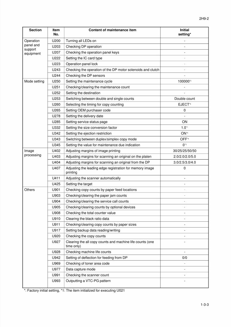
U200 Turning all LEDs on -
U203 Checking DP operation -
U207 Checking the operation panel keys -
U222 Setting the IC card type -
U223 Operation panel lock -
U243 Checking the operation of the DP motor solenoids and clutch -
U244 Checking the DP sensors -
Mode setting U250 Setting the maintenance cycle 100000*1
U251 Checking/clearing the maintenance count -
U252 Setting the destination -
U253 Switching between double and single counts Double count
U260 Selecting the timing for copy counting EJECT*1
U265 Setting OEM purchaser code 0
U278 Setting the delivery date -
U285 Setting service status page ON
U332 Setting the size conversion factor 1.0*1
U342 Setting the ejection restriction ON*1
U343 Switching between duplex/simplex copy mode OFF*1
U345 Setting the value for maintenance due indication 0*1
Image
processing
U402 Adjusting margins of image printing 30/25/25/50/50
U403 Adjusting margins for scanning an original on the platen 2.0/2.0/2.0/5.0
U404 Adjusting margins for scanning an original from the DP 3.0/2.5/3.0/4.0
U407 Adjusting the leading edge registration for memory image
printing
0
U411 Adjusting the scanner automatically -
U425 Setting the target -
Others U901 Checking copy counts by paper feed locations -
U903 Checking/clearing the paper jam counts -
U904 Checking/clearing the service call counts -
U905 Checking/clearing counts by optional devices -
U908 Checking the total counter value -
U910 Clearing the black ratio data -
U911 Checking/clearing copy counts by paper sizes -
U917 Setting backup data reading/writing -
U920 Checking the copy counts -
U927 Clearing the all copy counts and machine life counts (one
time only)
-
U928 Checking machine life counts -
U942 Setting of deflection for feeding from DP 0/0
U969 Checking of toner area code -
U977 Data capture mode -
U991 Checking the scanner count -
U993 Outputting a VTC-PG pattern -
Section Item
No.
Content of maintenance item Initial
setting*
*: Factory initial setting, *1: The item initialized for executing U021
8/3/2019 Servi manualKM-2810ENSMR3
http://slidepdf.com/reader/full/servi-manualkm-2810ensmr3 30/202
2H9-2
1-3-4
(3) Contents of the maintenance mode items
Maintenance
item No.Description
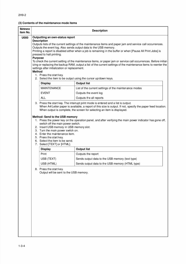
U000 Outputting an own-status report
Description
Outputs lists of the current settings of the maintenance items and paper jam and service call occurrences.
Outputs the event log. Also sends output data to the USB memory.
Printing a report is disabled either when a job is remaining in the buffer or when [Pause All Print Jobs] is
pressed to halt printing.
Purpose
To check the current setting of the maintenance items, or paper jam or service call occurrences. Before initial-
izing or replacing the backup RAM, output a list of the current settings of the maintenance items to reenter the
settings after initialization or replacement.
Method
1. Press the start key.
2. Select the item to be output using the cursor up/down keys.
3. Press the start key. The interrupt print mode is entered and a list is output.
When A4/Letter paper is available, a report of this size is output. If not, specify the paper feed location.
When output is complete, the screen for selecting an item is displayed.
Method: Send to the USB memory
1. Press the power key on the operation panel, and after verifying the main power indicator has gone off,
switch off the main power switch.
2. Insert USB memory in USB memory slot.
3. Turn the main power switch on.
4. Enter the maintenance item.
5. Press the start key.6. Select the item to be send.
7. Select [TEXT] or [HTML].
8. Press the start key.
Output will be sent to the USB memory.
Display Output list
MAINTENANCE List of the current settings of the maintenance modes
EVENT Outputs the event log
ALL Outputs the all reports
Display Output list
Print Outputs the report
USB (TEXT) Sends output data to the USB memory (text type)
USB (HTML) Sends output data to the USB memory (HTML type)
8/3/2019 Servi manualKM-2810ENSMR3
http://slidepdf.com/reader/full/servi-manualkm-2810ensmr3 31/202
2H9-2
1-3-5
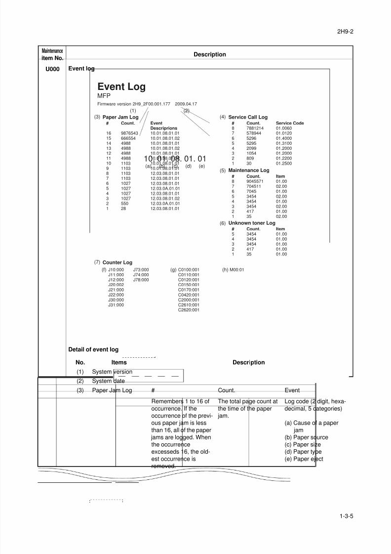
U000 Event log
Detail of event log
Maintenance
item No.Description
Firmware version 2H9_2F00.001.177
Paper Jam Log
Counter Log
2009.04.17
J10:000J11:000J12:000J20:002
J21:000J22:000J30:000J31:000
J73:000J74:000J78:000
C0100:001C0110:001C0120:001C0150:001
C0170:001C0420:001C2000:001C2610:001C2620:001
M00:01
#
1615141312111098765
4321
Count.
98765436665544988498849884988110311031103110310271027
1027102755028
EventDescriprions10.01.08.01.0110.01.08.01.0210.01.08.01.0110.01.08.01.0210.01.08.01.0110.01.08.01.0210.01.08.01.0110.01.08.01.0112.03.08.01.0112.03.08.01.0112.03.08.01.0112.03.0A.01.01
12.03.08.01.0112.03.08.01.0212.03.0A.01.0112.03.08.01.01
Service Call Log#87654321
Count.7881214578944529652952099105480930
Service Code01.006001.012001.400001.310001.200001.200001.220001.2500
Maintenance Log#87654321
Count.9045571704511704534543454345441735
Item01.0002.0001.0002.0001.0002.0001.0002.00
Unknown toner Log#54321
Count.34543454345441735
Item01.0001.0001.0001.0001.00
Event LogMFP
(f) (g) (h)
(a) (b) (c) (d) (e)
10. 01. 08. 01. 01
(1)
(3)
(7)
(4)
(5)
(6)
(2)
No. Items Description
(1) System version
(2) System date
(3) Paper Jam Log # Count. Event
Remembers 1 to 16 of
occurrence. If the
occurrence of the previ-
ous paper jam is less
than 16, all of the paper
jams are logged. When
the occurrence
excesseds 16, the old-
est occurrence is
removed.
The total page count at
the time of the paper
jam.
Log code (2 digit, hexa-
decimal, 5 categories)
(a) Cause of a paper
jam
(b) Paper source
(c) Paper size
(d) Paper type
(e) Paper eject
8/3/2019 Servi manualKM-2810ENSMR3
http://slidepdf.com/reader/full/servi-manualkm-2810ensmr3 32/202
2H9-2
1-3-6
U000
Completion
Press the stop key. The screen for selecting a maintenance item No. is displayed.
Maintenance
item No.Description
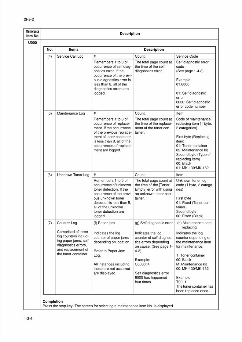
No. Items Description
(4) Service Call Log # Count. Service Code
Remembers 1 to 8 of
occurrence of self diag-
nostics error. If the
occurrence of the previ-
ous diagnostics error is
less than 8, all of the
diagnostics errors are
logged.
The total page count at
the time of the self
diagnostics error.
Self diagnostic error
code
(See page 1-4-3)
Example:
01.6000
01: Self diagnostic
error
6000: Self diagnostic
error code number
(5) Maintenance Log # Count. Item
Remembers 1 to 8 ofoccurrence of replace-
ment. If the occurrence
of the previous replace-
ment of toner container
is less than 8, all of the
occurrences of replace-
ment are logged.
The total page count atthe time of the replace-
ment of the toner con-
tainer.
Code of maintenancereplacing item (1 byte,
2 categories)
First byte (Replacing
item)
01: Toner container
02: Maintenance kit
Second byte (Type of
replacing item)
00: Black
01: MK-130/MK-132
(6) Unknown Toner Log # Count. Item
Remembers 1 to 5 ofoccurrence of unknown
toner detection. If the
occurrence of the previ-
ous unknown toner
detection is less than 5,
all of the unknown
toner detection are
logged.
The total page count atthe time of the [Toner
Empty] error with using
an unknown toner con-
tainer.
Unknown toner logcode (1 byte, 2 catego-
ries)
First byte
01: Fixed (Toner con-
tainer)
Second byte
00: Fixed (Black)
(7) Counter Log
Comprised of three
log counters includ-
ing paper jams, selfdiagnostics errors,
and replacement of
the toner container.
(f) Paper jam (g) Self diagnostic error (h) Maintenance item
replacing
Indicates the log
counter of paper jams
depending on location.
Refer to Paper Jam
Log.
All instances including
those are not occurred
are displayed.
Indicates the log
counter of self diagnos-
tics errors depending
on cause. (See page 1-
4-3)
Example:
C6000: 4
Self diagnostics error
6000 has happened
four times.
Indicates the log
counter depending on
the maintenance item
for maintenance.
T: Toner container
00: Black
M: Maintenance kit
00: MK-130/MK-132
Example:
T00: 1
The toner container has
been replaced once.
8/3/2019 Servi manualKM-2810ENSMR3
http://slidepdf.com/reader/full/servi-manualkm-2810ensmr3 33/202
2H9-2
1-3-7
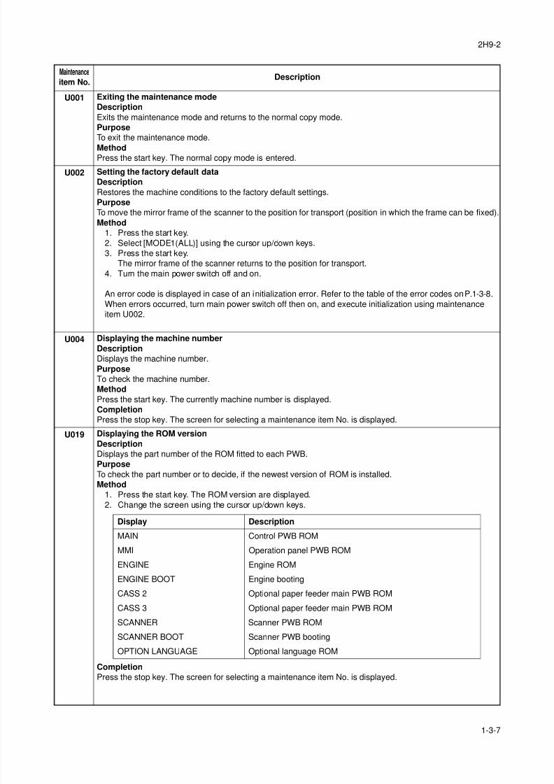
U001 Exiting the maintenance mode
Description
Exits the maintenance mode and returns to the normal copy mode.
Purpose
To exit the maintenance mode.Method
Press the start key. The normal copy mode is entered.
U002 Setting the factory default data
Description
Restores the machine conditions to the factory default settings.
Purpose
To move the mirror frame of the scanner to the position for transport (position in which the frame can be fixed).
Method
1. Press the start key.
2. Select [MODE1(ALL)] using the cursor up/down keys.
3. Press the start key.
The mirror frame of the scanner returns to the position for transport.
4. Turn the main power switch off and on.
An error code is displayed in case of an initialization error. Refer to the table of the error codes on P.1-3-8.
When errors occurred, turn main power switch off then on, and execute initialization using maintenance
item U002.
U004 Displaying the machine number
Description
Displays the machine number.
Purpose
To check the machine number.
Method
Press the start key. The currently machine number is displayed.
CompletionPress the stop key. The screen for selecting a maintenance item No. is displayed.
U019 Displaying the ROM version
Description
Displays the part number of the ROM fitted to each PWB.
Purpose
To check the part number or to decide, if the newest version of ROM is installed.
Method
1. Press the start key. The ROM version are displayed.
2. Change the screen using the cursor up/down keys.
Completion
Press the stop key. The screen for selecting a maintenance item No. is displayed.
Maintenance
item No.Description
Display Description
MAIN Control PWB ROM
MMI Operation panel PWB ROM
ENGINE Engine ROM
ENGINE BOOT Engine booting
CASS 2 Optional paper feeder main PWB ROM
CASS 3 Optional paper feeder main PWB ROM
SCANNER Scanner PWB ROM
SCANNER BOOT Scanner PWB booting
OPTION LANGUAGE Optional language ROM
8/3/2019 Servi manualKM-2810ENSMR3
http://slidepdf.com/reader/full/servi-manualkm-2810ensmr3 34/202
2H9-1
1-3-8
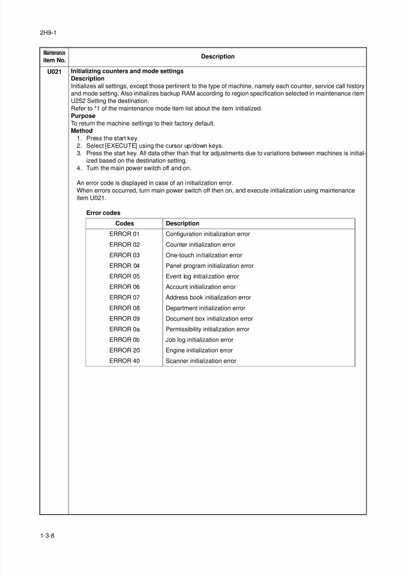
U021 Initializing counters and mode settings
Description
Initializes all settings, except those pertinent to the type of machine, namely each counter, service call history
and mode setting. Also initializes backup RAM according to region specification selected in maintenance item
U252 Setting the destination.Refer to *1 of the maintenance mode item list about the item initialized.
Purpose
To return the machine settings to their factory default.
Method
1. Press the start key.
2. Select [EXECUTE] using the cursor up/down keys.
3. Press the start key. All data other than that for adjustments due to variations between machines is initial-
ized based on the destination setting.
4. Turn the main power switch off and on.
An error code is displayed in case of an initialization error.
When errors occurred, turn main power switch off then on, and execute initialization using maintenance
item U021.
Error codes
Maintenance
item No.Description
Codes Description
ERROR 01 Configuration initialization error
ERROR 02 Counter initialization error
ERROR 03 One-touch initialization error
ERROR 04 Panel program initialization error
ERROR 05 Event log initialization error
ERROR 06 Account initialization error
ERROR 07 Address book initialization error
ERROR 08 Department initialization error
ERROR 09 Document box initialization error
ERROR 0a Permissibility initialization error
ERROR 0b Job log initialization error
ERROR 20 Engine initialization error
ERROR 40 Scanner initialization error
8/3/2019 Servi manualKM-2810ENSMR3
http://slidepdf.com/reader/full/servi-manualkm-2810ensmr3 35/202
2H9-1
1-3-9
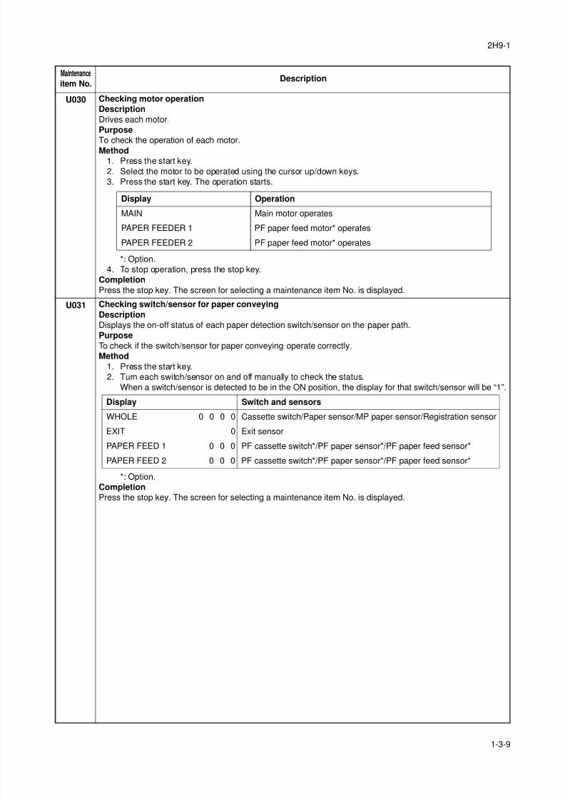
U030 Checking motor operation
Description
Drives each motor.
Purpose
To check the operation of each motor.Method
1. Press the start key.
2. Select the motor to be operated using the cursor up/down keys.
3. Press the start key. The operation starts.
*: Option.
4. To stop operation, press the stop key.
CompletionPress the stop key. The screen for selecting a maintenance item No. is displayed.
U031 Checking switch/sensor for paper conveying
Description
Displays the on-off status of each paper detection switch/sensor on the paper path.
Purpose
To check if the switch/sensor for paper conveying operate correctly.
Method
1. Press the start key.
2. Turn each switch/sensor on and off manually to check the status.
When a switch/sensor is detected to be in the ON position, the display for that switch/sensor will be “1”.
*: Option.
Completion
Press the stop key. The screen for selecting a maintenance item No. is displayed.
Maintenance
item No.Description
Display Operation
MAIN Main motor operates
PAPER FEEDER 1 PF paper feed motor* operates
PAPER FEEDER 2 PF paper feed motor* operates
Display Switch and sensors
WHOLE 0 0 0 0 Cassette switch/Paper sensor/MP paper sensor/Registration sensorEXIT 0 Exit sensor
PAPER FEED 1 0 0 0 PF cassette switch*/PF paper sensor*/PF paper feed sensor*
PAPER FEED 2 0 0 0 PF cassette switch*/PF paper sensor*/PF paper feed sensor*
8/3/2019 Servi manualKM-2810ENSMR3
http://slidepdf.com/reader/full/servi-manualkm-2810ensmr3 36/202
2H9-1
1-3-10
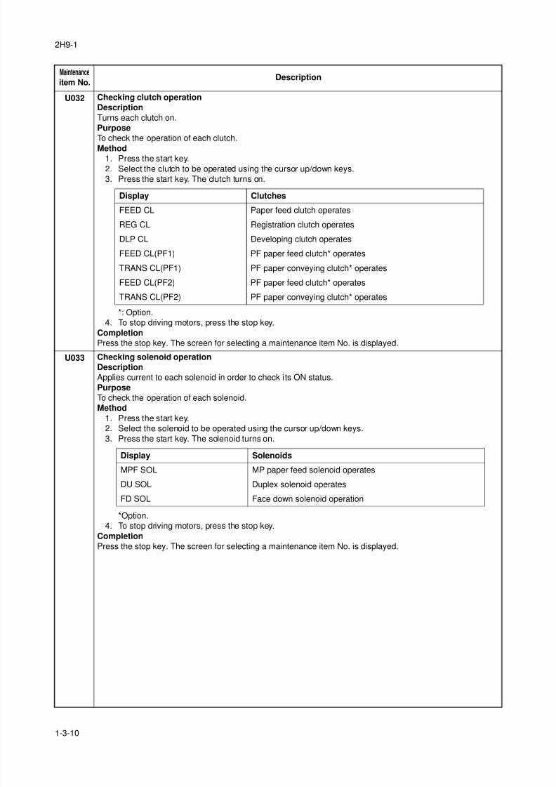
U032 Checking clutch operation
Description
Turns each clutch on.
Purpose
To check the operation of each clutch.Method
1. Press the start key.
2. Select the clutch to be operated using the cursor up/down keys.
3. Press the start key. The clutch turns on.
*: Option.
4. To stop driving motors, press the stop key.
Completion
Press the stop key. The screen for selecting a maintenance item No. is displayed.
U033 Checking solenoid operation
Description
Applies current to each solenoid in order to check its ON status.
Purpose
To check the operation of each solenoid.
Method
1. Press the start key.
2. Select the solenoid to be operated using the cursor up/down keys.
3. Press the start key. The solenoid turns on.
*Option.
4. To stop driving motors, press the stop key.
Completion
Press the stop key. The screen for selecting a maintenance item No. is displayed.
Maintenance
item No.Description
Display Clutches
FEED CL Paper feed clutch operates
REG CL Registration clutch operates
DLP CL Developing clutch operates
FEED CL(PF1) PF paper feed clutch* operates
TRANS CL(PF1) PF paper conveying clutch* operates
FEED CL(PF2) PF paper feed clutch* operates
TRANS CL(PF2) PF paper conveying clutch* operates
Display Solenoids
MPF SOL MP paper feed solenoid operates
DU SOL Duplex solenoid operates
FD SOL Face down solenoid operation
8/3/2019 Servi manualKM-2810ENSMR3
http://slidepdf.com/reader/full/servi-manualkm-2810ensmr3 37/202
2H9-1
1-3-11
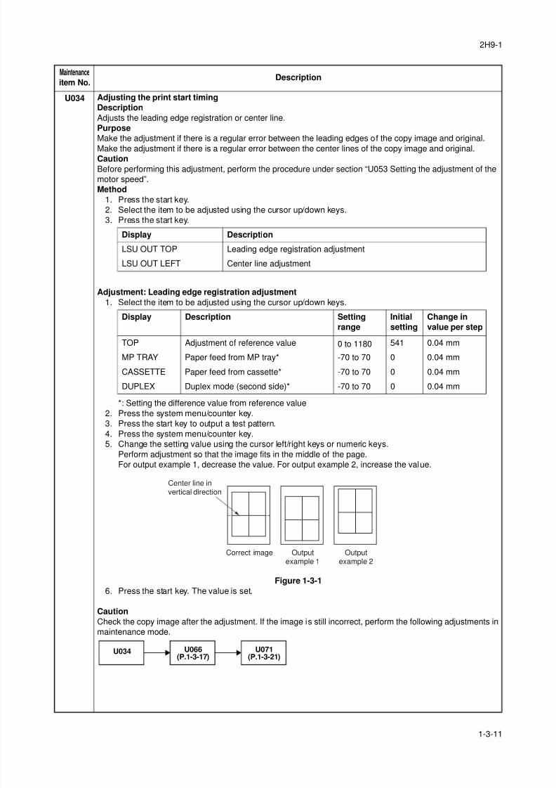
U034 Adjusting the print start timing
Description
Adjusts the leading edge registration or center line.
Purpose
Make the adjustment if there is a regular error between the leading edges of the copy image and original.Make the adjustment if there is a regular error between the center lines of the copy image and original.
Caution
Before performing this adjustment, perform the procedure under section “U053 Setting the adjustment of the
motor speed”.
Method
1. Press the start key.
2. Select the item to be adjusted using the cursor up/down keys.
3. Press the start key.
Adjustment: Leading edge registration adjustment
1. Select the item to be adjusted using the cursor up/down keys.
*: Setting the difference value from reference value
2. Press the system menu/counter key.3. Press the start key to output a test pattern.
4. Press the system menu/counter key.
5. Change the setting value using the cursor left/right keys or numeric keys.
Perform adjustment so that the image fits in the middle of the page.
For output example 1, decrease the value. For output example 2, increase the value.
Figure 1-3-1
6. Press the start key. The value is set.
Caution
Check the copy image after the adjustment. If the image is still incorrect, perform the following adjustments in
maintenance mode.
Maintenance
item No.Description
Display Description
LSU OUT TOP Leading edge registration adjustment
LSU OUT LEFT Center line adjustment
Display Description Setting
range
Initial
setting
Change in
value per step
TOP Adjustment of reference value 0 to 1180 541 0.04 mm
MP TRAY Paper feed from MP tray* -70 to 70 0 0.04 mm
CASSETTE Paper feed from cassette* -70 to 70 0 0.04 mm
DUPLEX Duplex mode (second side)* -70 to 70 0 0.04 mm
Center line invertical direction
Correct image Outputexample 1
Outputexample 2
U034 U066(P.1-3-17)
U071(P.1-3-21)
8/3/2019 Servi manualKM-2810ENSMR3
http://slidepdf.com/reader/full/servi-manualkm-2810ensmr3 38/202
2H9-1
1-3-12
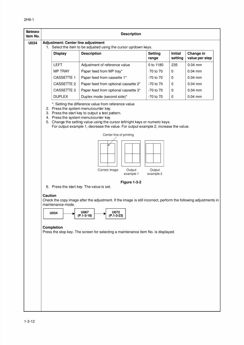
U034 Adjustment: Center line adjustment
1. Select the item to be adjusted using the cursor up/down keys.
*: Setting the difference value from reference value
2. Press the system menu/counter key.
3. Press the start key to output a test pattern.
4. Press the system menu/counter key.
5. Change the setting value using the cursor left/right keys or numeric keys.For output example 1, decrease the value. For output example 2, increase the value.
Figure 1-3-26. Press the start key. The value is set.
Caution
Check the copy image after the adjustment. If the image is still incorrect, perform the following adjustments in
maintenance mode.
Completion
Press the stop key. The screen for selecting a maintenance item No. is displayed.
Maintenance
item No.Description
Display Description Setting
range
Initial
setting
Change in
value per step
LEFT Adjustment of reference value 0 to 1180 235 0.04 mm
MP TRAY Paper feed from MP tray* -70 to 70 0 0.04 mm
CASSETTE 1 Paper feed from cassette 1* -70 to 70 0 0.04 mm
CASSETTE 2 Paper feed from optional cassette 2* -70 to 70 0 0.04 mm
CASSETTE 3 Paper feed from optional cassette 3* -70 to 70 0 0.04 mm
DUPLEX Duplex mode (second side)* -70 to 70 0 0.04 mm
Center line of printing
Correct image Outputexample 1
Outputexample 2
U034 U067(P.1-3-18)
U072(P.1-3-23)
8/3/2019 Servi manualKM-2810ENSMR3
http://slidepdf.com/reader/full/servi-manualkm-2810ensmr3 39/202
2H9-2
1-3-13
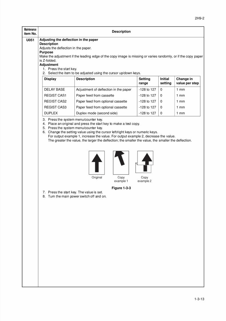
U051 Adjusting the deflection in the paper
Description
Adjusts the deflection in the paper.
Purpose
Make the adjustment if the leading edge of the copy image is missing or varies randomly, or if the copy paperis Z-folded.
Adjustment
1. Press the start key.
2. Select the item to be adjusted using the cursor up/down keys.
3. Press the system menu/counter key.
4. Place an original and press the start key to make a test copy.
5. Press the system menu/counter key.
6. Change the setting value using the cursor left/right keys or numeric keys.
For output example 1, increase the value. For output example 2, decrease the value.
The greater the value, the larger the deflection; the smaller the value, the smaller the deflection.
Figure 1-3-3
7. Press the start key. The value is set.
8. Turn the main power switch off and on.
Maintenance
item No.Description
Display Description Setting
range
Initial
setting
Change in
value per step
DELAY BASE Adjustment of deflection in the paper -128 to 127 0 1 mm
REGIST CAS1 Paper feed from cassette -128 to 127 0 1 mm
REGIST CAS2 Paper feed from optional cassette -128 to 127 0 1 mm
REGIST CAS3 Paper feed from optional cassette -128 to 127 0 1 mm
DUPLEX Duplex mode (second side) -128 to 127 0 1 mm
Original Copyexample 1
Copyexample 2
8/3/2019 Servi manualKM-2810ENSMR3
http://slidepdf.com/reader/full/servi-manualkm-2810ensmr3 40/202
2H9-2
1-3-14
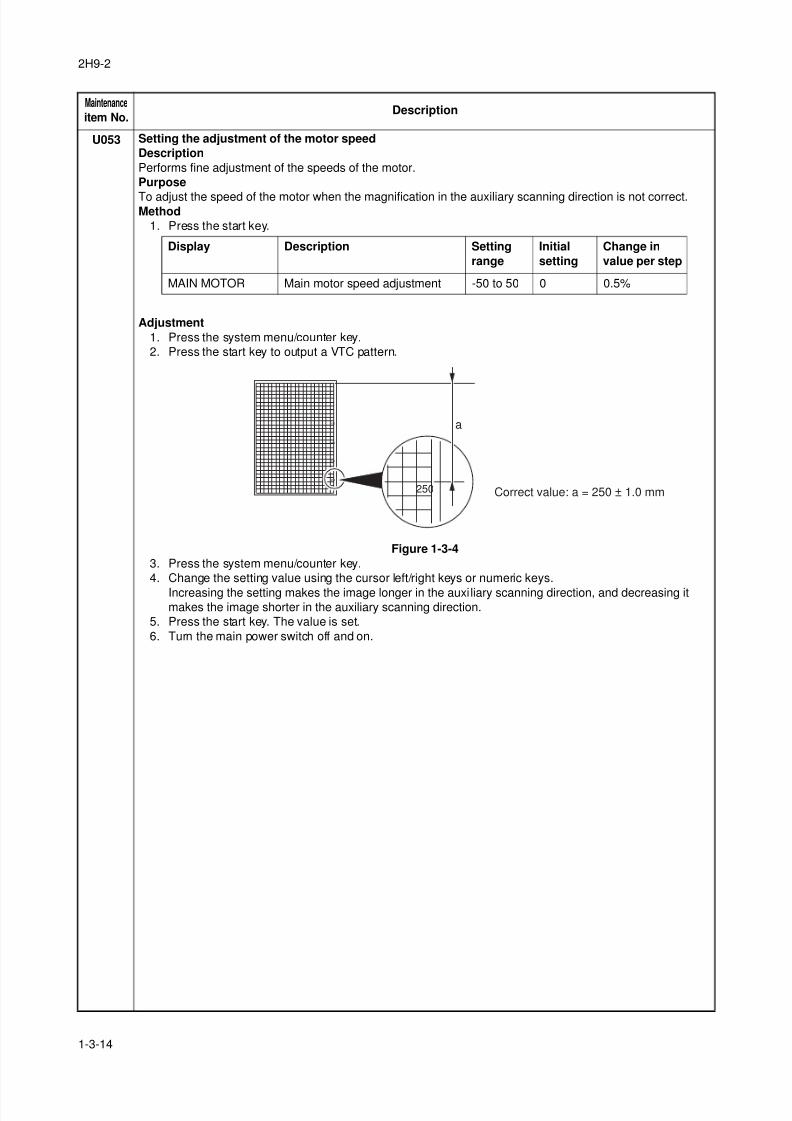
U053 Setting the adjustment of the motor speed
Description
Performs fine adjustment of the speeds of the motor.
Purpose
To adjust the speed of the motor when the magnification in the auxiliary scanning direction is not correct.Method
1. Press the start key.
Adjustment
1. Press the system menu/counter key.
2. Press the start key to output a VTC pattern.
Figure 1-3-4
3. Press the system menu/counter key.
4. Change the setting value using the cursor left/right keys or numeric keys.
Increasing the setting makes the image longer in the auxiliary scanning direction, and decreasing itmakes the image shorter in the auxiliary scanning direction.
5. Press the start key. The value is set.
6. Turn the main power switch off and on.
Maintenance
item No.Description
Display Description Setting
range
Initial
setting
Change in
value per step
MAIN MOTOR Main motor speed adjustment -50 to 50 0 0.5%
100
150
200
250
250 Correct value: a = 250 ± 1.0 mm
a
8/3/2019 Servi manualKM-2810ENSMR3
http://slidepdf.com/reader/full/servi-manualkm-2810ensmr3 41/202
2H9-1
1-3-15
U063 Adjusting the shading position
Description
Changes the shading position of the scanner.
Purpose
Used when white lines continue to appear longitudinally on the image after the shading plate is cleaned. Thisis due to flaws or stains inside the shading plate. To prevent this problem, the shading position should be
changed so that shading is possible without being affected by the flaws or stains.
Method
1. Press the start key.
2. Change the setting using the cursor left/right keys or numeric keys.
Increasing the setting moves the shading position toward the machine left, and decreasing it moves the
position toward the machine right.
3. Press the start key. The value is set.
Supplement
While this maintenance item is being executed, copying from an original is available in interrupt copying mode(which is activated by pressing the system menu/counter key).
Completion
Press the stop key. The screen for selecting a maintenance item No. is displayed.
Maintenance
item No.Description
Description Setting range Initial setting Change in value per step
Shading position -32 to 20 0 0.086 mm
8/3/2019 Servi manualKM-2810ENSMR3
http://slidepdf.com/reader/full/servi-manualkm-2810ensmr3 42/202
2H9-1
1-3-16
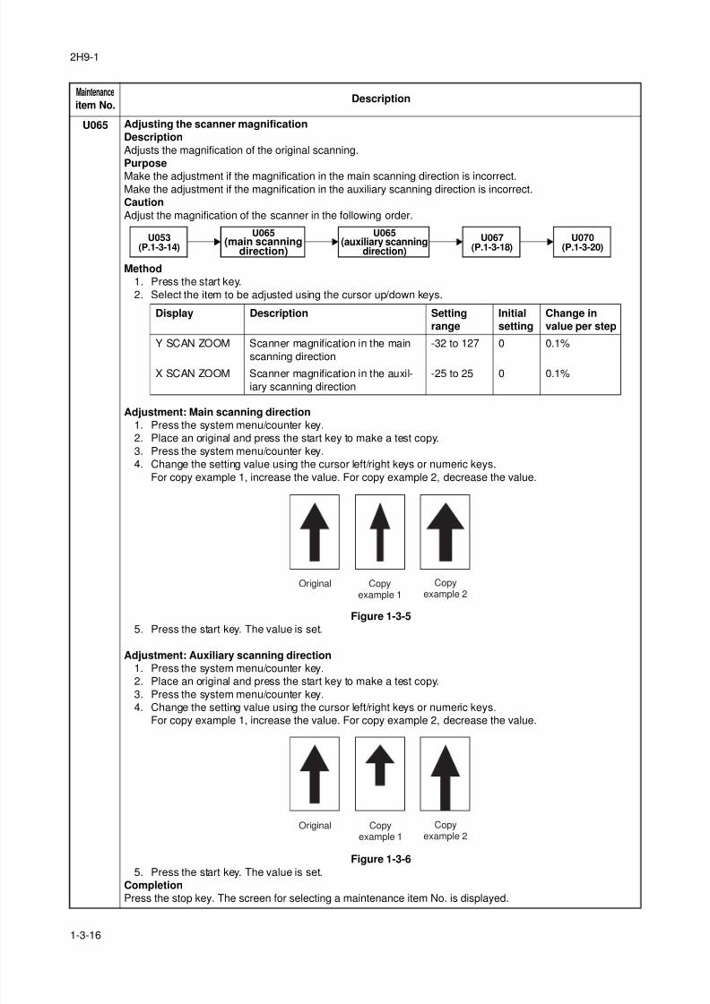
U065 Adjusting the scanner magnification
Description
Adjusts the magnification of the original scanning.
Purpose
Make the adjustment if the magnification in the main scanning direction is incorrect.Make the adjustment if the magnification in the auxiliary scanning direction is incorrect.
Caution
Adjust the magnification of the scanner in the following order.
Method
1. Press the start key.
2. Select the item to be adjusted using the cursor up/down keys.
Adjustment: Main scanning direction
1. Press the system menu/counter key.
2. Place an original and press the start key to make a test copy.
3. Press the system menu/counter key.
4. Change the setting value using the cursor left/right keys or numeric keys.
For copy example 1, increase the value. For copy example 2, decrease the value.
Figure 1-3-5
5. Press the start key. The value is set.
Adjustment: Auxiliary scanning direction
1. Press the system menu/counter key.
2. Place an original and press the start key to make a test copy.
3. Press the system menu/counter key.
4. Change the setting value using the cursor left/right keys or numeric keys.For copy example 1, increase the value. For copy example 2, decrease the value.
Figure 1-3-6
5. Press the start key. The value is set.
Completion
Press the stop key. The screen for selecting a maintenance item No. is displayed.
Maintenance
item No.Description
U065(main scanning
direction)
U053(P.1-3-14)
U067(P.1-3-18)
U065(auxiliary scanning
direction)
U070(P.1-3-20)
Display Description Setting
range
Initial
setting
Change in
value per step
Y SCAN ZOOM Scanner magnification in the main
scanning direction
-32 to 127 0 0.1%
X SCAN ZOOM Scanner magnification in the auxil-
iary scanning direction
-25 to 25 0 0.1%
Original Copyexample 1
Copyexample 2
Original Copyexample 1
Copyexample 2
8/3/2019 Servi manualKM-2810ENSMR3
http://slidepdf.com/reader/full/servi-manualkm-2810ensmr3 43/202
2H9-1
1-3-17
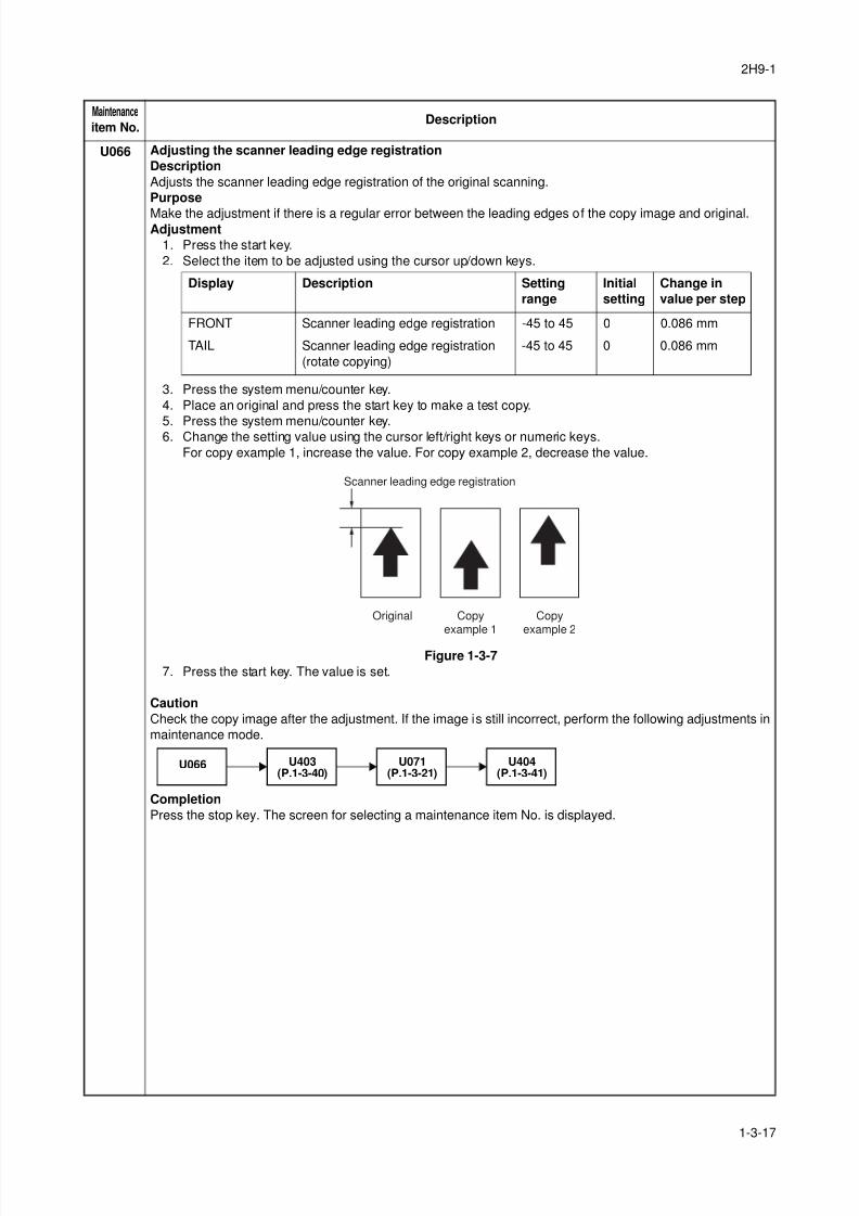
U066 Adjusting the scanner leading edge registration
Description
Adjusts the scanner leading edge registration of the original scanning.
Purpose
Make the adjustment if there is a regular error between the leading edges of the copy image and original.Adjustment
1. Press the start key.
2. Select the item to be adjusted using the cursor up/down keys.
3. Press the system menu/counter key.
4. Place an original and press the start key to make a test copy.
5. Press the system menu/counter key.6. Change the setting value using the cursor left/right keys or numeric keys.
For copy example 1, increase the value. For copy example 2, decrease the value.
Figure 1-3-7
7. Press the start key. The value is set.
Caution
Check the copy image after the adjustment. If the image is still incorrect, perform the following adjustments in
maintenance mode.
Completion
Press the stop key. The screen for selecting a maintenance item No. is displayed.
Maintenance
item No.Description
Display Description Setting
range
Initial
setting
Change in
value per step
FRONT Scanner leading edge registration -45 to 45 0 0.086 mm
TAIL Scanner leading edge registration
(rotate copying)
-45 to 45 0 0.086 mm
Original
Scanner leading edge registration
Copyexample 1
Copyexample 2
U066 U403(P.1-3-40)
U071(P.1-3-21)
U404(P.1-3-41)
8/3/2019 Servi manualKM-2810ENSMR3
http://slidepdf.com/reader/full/servi-manualkm-2810ensmr3 44/202
2H9-1
1-3-18
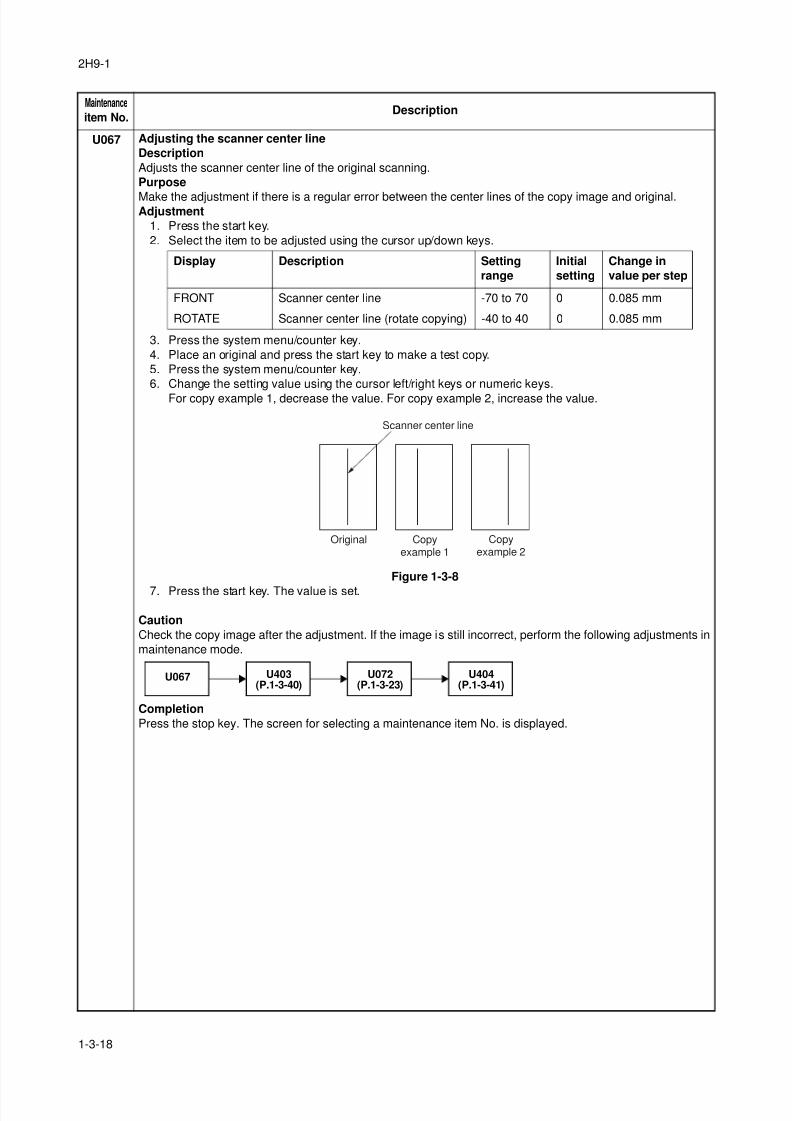
U067 Adjusting the scanner center line
Description
Adjusts the scanner center line of the original scanning.
Purpose
Make the adjustment if there is a regular error between the center lines of the copy image and original.Adjustment
1. Press the start key.
2. Select the item to be adjusted using the cursor up/down keys.
3. Press the system menu/counter key.
4. Place an original and press the start key to make a test copy.
5. Press the system menu/counter key.
6. Change the setting value using the cursor left/right keys or numeric keys.
For copy example 1, decrease the value. For copy example 2, increase the value.
Figure 1-3-8
7. Press the start key. The value is set.
Caution
Check the copy image after the adjustment. If the image is still incorrect, perform the following adjustments in
maintenance mode.
Completion
Press the stop key. The screen for selecting a maintenance item No. is displayed.
Maintenance
item No.Description
Display Description Setting
range
Initial
setting
Change in
value per step
FRONT Scanner center line -70 to 70 0 0.085 mm
ROTATE Scanner center line (rotate copying) -40 to 40 0 0.085 mm
Original Copyexample 1
Copyexample 2
Scanner center line
U067 U403(P.1-3-40)
U072(P.1-3-23)
U404(P.1-3-41)
8/3/2019 Servi manualKM-2810ENSMR3
http://slidepdf.com/reader/full/servi-manualkm-2810ensmr3 45/202
2H9-1
1-3-19
U068 Adjusting the scanning position for originals from the DP
Description
Adjusts the position for scanning originals from the DP. Performs the test copy at the four scanning positions
after adjusting.
PurposeUsed when the image fogging occurs because the scanning position is not proper when the DP is used. Run
U071 to adjust the timing of DP leading edge when the scanning position is changed.
Setting
1. Press the start key.
2. Select [DP READ].
3. Change the setting using the cursor left/right keys or numeric keys.When the setting value is increased, the scanning position moves to the right and it moves to the left
when the setting value is decreased.
4. Press the start key. The value is set.
5. Select [BLACK LINE] using the cursor up/down keys.
6. Select the scanning position using the cursor left/right keys or numeric keys.
7. Press the start key. The value is set.
8. Set the original (the one which density is known) in the DP and press the system menu/counter key. The
screen for the test copy mode is displayed.
9. Press the start key. Test copy is executed.
10. Perform the test copy at each scanning position with the setting value from 0 to 3 and check that no
black line appears and the image is normally scanned.
Completion
Press the stop key. The screen for selecting a maintenance item No. is displayed.
Maintenance
item No.Description
Display Description Setting
range
Initial
setting
Change in
value per step
DP READ Starting position adjustment for
scanning originals
-33 to 33 0 0.086 mm
BLACK LINE Scanning position for the test copy
originals
0 to 3 0 0.22 mm
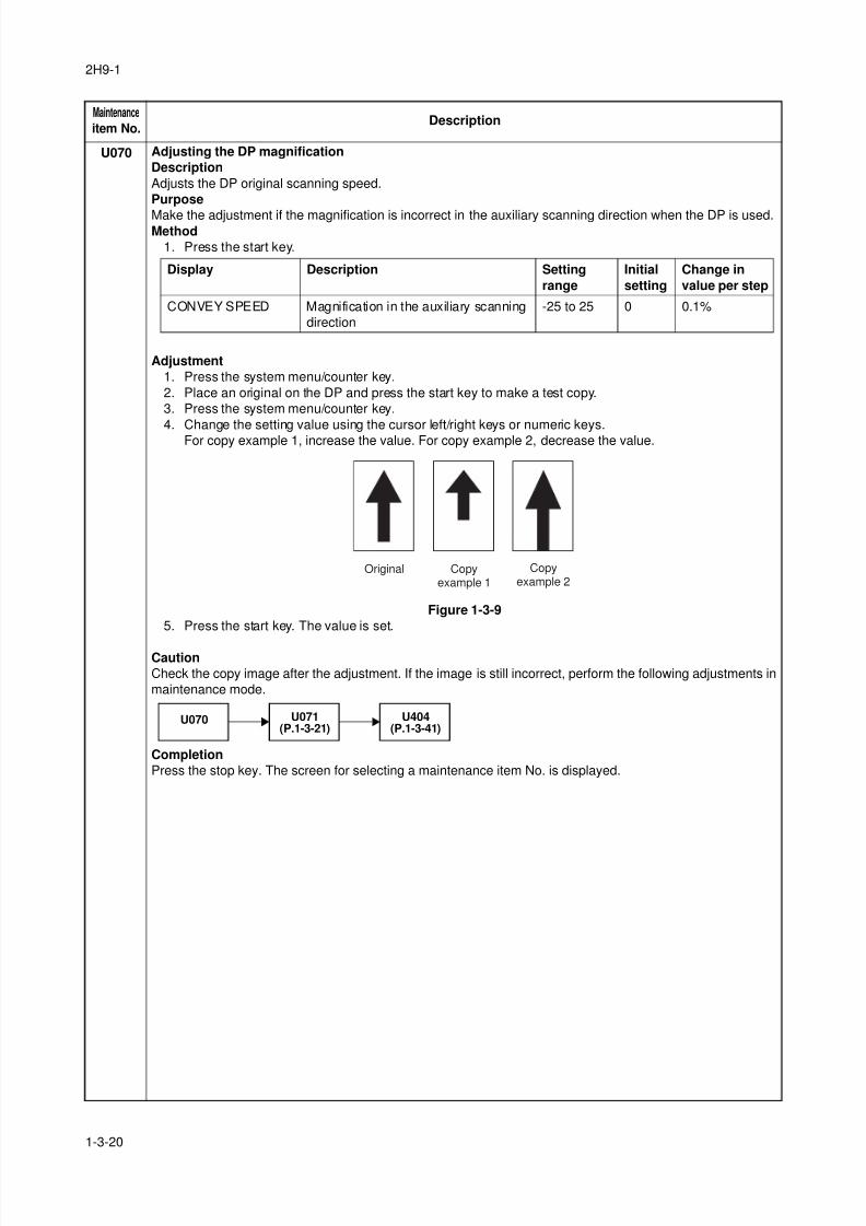
8/3/2019 Servi manualKM-2810ENSMR3
http://slidepdf.com/reader/full/servi-manualkm-2810ensmr3 46/202
2H9-1
1-3-20
U070 Adjusting the DP magnification
Description
Adjusts the DP original scanning speed.
Purpose
Make the adjustment if the magnification is incorrect in the auxiliary scanning direction when the DP is used.Method
1. Press the start key.
Adjustment
1. Press the system menu/counter key.
2. Place an original on the DP and press the start key to make a test copy.
3. Press the system menu/counter key.
4. Change the setting value using the cursor left/right keys or numeric keys.For copy example 1, increase the value. For copy example 2, decrease the value.
Figure 1-3-9
5. Press the start key. The value is set.
Caution
Check the copy image after the adjustment. If the image is still incorrect, perform the following adjustments in
maintenance mode.
Completion
Press the stop key. The screen for selecting a maintenance item No. is displayed.
Maintenance
item No.Description
Display Description Setting
range
Initial
setting
Change in
value per step
CONVEY SPEED Magnification in the auxiliary scanning
direction
-25 to 25 0 0.1%
Original Copyexample 1
Copyexample 2
U070 U071(P.1-3-21)
U404(P.1-3-41)
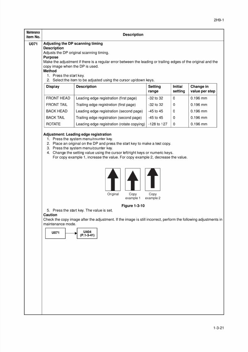
8/3/2019 Servi manualKM-2810ENSMR3
http://slidepdf.com/reader/full/servi-manualkm-2810ensmr3 47/202
2H9-1
1-3-21
U071 Adjusting the DP scanning timing
Description
Adjusts the DP original scanning timing.
Purpose
Make the adjustment if there is a regular error between the leading or trailing edges of the original and thecopy image when the DP is used.
Method
1. Press the start key.
2. Select the item to be adjusted using the cursor up/down keys.
Adjustment: Leading edge registration
1. Press the system menu/counter key.
2. Place an original on the DP and press the start key to make a test copy.
3. Press the system menu/counter key.
4. Change the setting value using the cursor left/right keys or numeric keys.
For copy example 1, increase the value. For copy example 2, decrease the value.
Figure 1-3-10
5. Press the start key. The value is set.
Caution
Check the copy image after the adjustment. If the image is still incorrect, perform the following adjustments in
maintenance mode.
Maintenance
item No.Description
Display Description Setting
range
Initial
setting
Change in
value per step
FRONT HEAD Leading edge registration (first page) -32 to 32 0 0.196 mm
FRONT TAIL Trailing edge registration (first page) -32 to 32 0 0.196 mm
BACK HEAD Leading edge registration (second page) -45 to 45 0 0.196 mm
BACK TAIL Trailing edge registration (second page) -45 to 45 0 0.196 mm
ROTATE Leading edge registration (rotate copying) -128 to 127 0 0.196 mm
Original Copyexample 1
Copyexample 2
U071 U404(P.1-3-41)
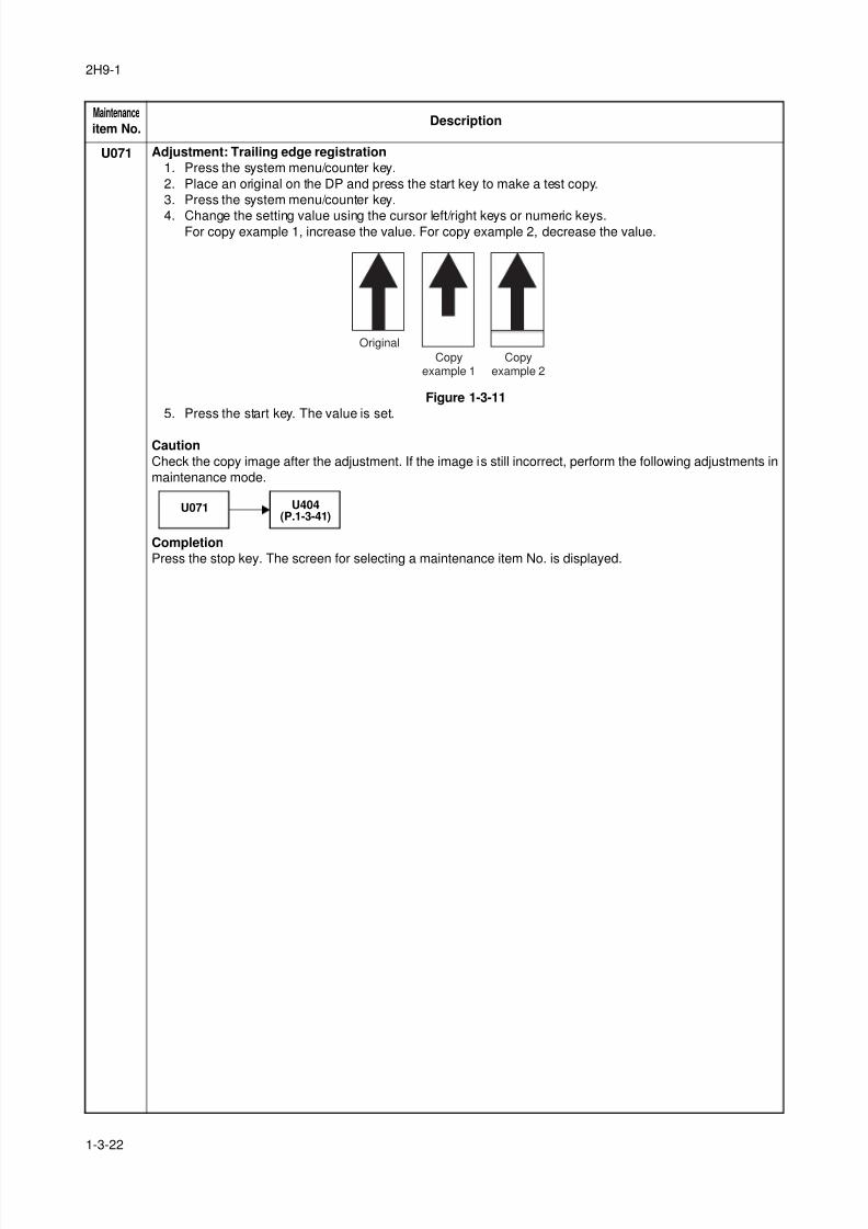
8/3/2019 Servi manualKM-2810ENSMR3
http://slidepdf.com/reader/full/servi-manualkm-2810ensmr3 48/202
2H9-1
1-3-22
U071 Adjustment: Trailing edge registration
1. Press the system menu/counter key.
2. Place an original on the DP and press the start key to make a test copy.
3. Press the system menu/counter key.
4. Change the setting value using the cursor left/right keys or numeric keys.For copy example 1, increase the value. For copy example 2, decrease the value.
Figure 1-3-11
5. Press the start key. The value is set.
Caution
Check the copy image after the adjustment. If the image is still incorrect, perform the following adjustments in
maintenance mode.
Completion
Press the stop key. The screen for selecting a maintenance item No. is displayed.
Maintenance
item No.Description
Original
Copyexample 1
Copyexample 2
U071 U404(P.1-3-41)
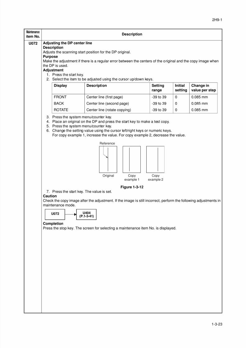
8/3/2019 Servi manualKM-2810ENSMR3
http://slidepdf.com/reader/full/servi-manualkm-2810ensmr3 49/202
2H9-1
1-3-23
U072 Adjusting the DP center line
Description
Adjusts the scanning start position for the DP original.
Purpose
Make the adjustment if there is a regular error between the centers of the original and the copy image whenthe DP is used.
Adjustment
1. Press the start key.
2. Select the item to be adjusted using the cursor up/down keys.
3. Press the system menu/counter key.
4. Place an original on the DP and press the start key to make a test copy.5. Press the system menu/counter key.
6. Change the setting value using the cursor left/right keys or numeric keys.
For copy example 1, increase the value. For copy example 2, decrease the value.
Figure 1-3-12
7. Press the start key. The value is set.
Caution
Check the copy image after the adjustment. If the image is still incorrect, perform the following adjustments in
maintenance mode.
Completion
Press the stop key. The screen for selecting a maintenance item No. is displayed.
Maintenance
item No.Description
Display Description Setting
range
Initial
setting
Change in
value per step
FRONT Center line (first page) -39 to 39 0 0.085 mm
BACK Center line (second page) -39 to 39 0 0.085 mm
ROTATE Center line (rotate copying) -39 to 39 0 0.085 mm
Original Copyexample 1
Copyexample 2
Reference
U072 U404(P.1-3-41)
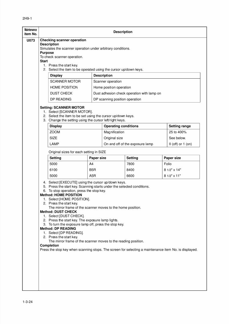
8/3/2019 Servi manualKM-2810ENSMR3
http://slidepdf.com/reader/full/servi-manualkm-2810ensmr3 50/202
2H9-1
1-3-24
U073 Checking scanner operation
Description
Simulates the scanner operation under arbitrary conditions.
Purpose
To check scanner operation.Start
1. Press the start key.
2. Select the item to be operated using the cursor up/down keys.
Setting: SCANNER MOTOR
1. Select [SCANNER MOTOR].2. Select the item to be set using the cursor up/down keys.
3. Change the setting using the cursor left/right keys.
Original sizes for each setting in SIZE
4. Select [EXECUTE] using the cursor up/down keys.
5. Press the start key. Scanning starts under the selected conditions.
6. To stop operation, press the stop key.
Method: HOME POSITION
1. Select [HOME POSITION].
2. Press the start key.
The mirror frame of the scanner moves to the home position.
Method: DUST CHECK
1. Select [DUST CHECK].
2. Press the start key. The exposure lamp lights.
3. To turn the exposure lamp off, press the stop key.
Method: DP READING
1. Select [DP READING].
2. Press the start key.
The mirror frame of the scanner moves to the reading position.
Completion
Press the stop key when scanning stops. The screen for selecting a maintenance item No. is displayed.
Maintenance
item No.Description
Display Description
SCANNER MOTOR Scanner operation
HOME POSITION Home position operation
DUST CHECK Dust adhesion check operation with lamp on
DP READING DP scanning position operation
Display Operating conditions Setting range
ZOOM Magnification 25 to 400%
SIZE Original size See below.
LAMP On and off of the exposure lamp 0 (off) or 1 (on)
Setting Paper size Setting Paper size
5000 A4 7800 Folio
6100 B5R 8400 8 1/2" x 14"5000 A5R 6600 8 1/2" x 11"
8/3/2019 Servi manualKM-2810ENSMR3
http://slidepdf.com/reader/full/servi-manualkm-2810ensmr3 51/202
2H9-1
1-3-25
U087 Setting DP reading position modification operation
Description
The presence or absence of dust is determined by comparing the scan data of the original trailing edge and
that taken after the original is conveyed past the DP original scanning position. If dust is identified, the DP
original scanning position is adjusted for the following originals.Purpose
When using DP, to solve the problem when black lines occurs due to the dust with respect to original reading
position.
Method
1. Press the start key.
2. Select the item to be set using the cursor up/down keys.
Setting: Standard data when dust is detected
1. Select the item to be set using the cursor up/down keys.2. Change the value using the cursor left/right keys or numeric keys.
3. Press the start key. The value is set.
Setting: Initialization of original reading position
1. Select [CLEAR] using the cursor up/down keys.
2. Press the start key. The setting is cleared.
Completion
Press the stop key. The screen for selecting a maintenance item No. is displayed.
Maintenance
item No.Description
Display Description
CCD Setting of standard data when dust is detected.
BLACK LINE Initialization of original reading position.
Display Description Setting range Initial setting
CCD R Lowest density of the R regard as the dust 0 to 255 125
CCD G Lowest density of the G regard as the dust 0 to 255 125
CCD B Lowest density of the B regard as the dust 0 to 255 120
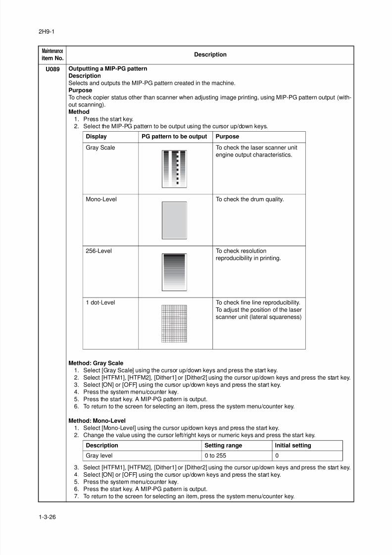
8/3/2019 Servi manualKM-2810ENSMR3
http://slidepdf.com/reader/full/servi-manualkm-2810ensmr3 52/202
2H9-1
1-3-26
U089 Outputting a MIP-PG pattern
Description
Selects and outputs the MIP-PG pattern created in the machine.
Purpose
To check copier status other than scanner when adjusting image printing, using MIP-PG pattern output (with-out scanning).
Method
1. Press the start key.
2. Select the MIP-PG pattern to be output using the cursor up/down keys.
Method: Gray Scale
1. Select [Gray Scale] using the cursor up/down keys and press the start key.
2. Select [HTFM1], [HTFM2], [Dither1] or [Dither2] using the cursor up/down keys and press the start key.
3. Select [ON] or [OFF] using the cursor up/down keys and press the start key.
4. Press the system menu/counter key.
5. Press the start key. A MIP-PG pattern is output.
6. To return to the screen for selecting an item, press the system menu/counter key.
Method: Mono-Level
1. Select [Mono-Level] using the cursor up/down keys and press the start key.
2. Change the value using the cursor left/right keys or numeric keys and press the start key.
3. Select [HTFM1], [HTFM2], [Dither1] or [Dither2] using the cursor up/down keys and press the start key.
4. Select [ON] or [OFF] using the cursor up/down keys and press the start key.
5. Press the system menu/counter key.
6. Press the start key. A MIP-PG pattern is output.
7. To return to the screen for selecting an item, press the system menu/counter key.
Maintenance
item No.Description
Display PG pattern to be output Purpose
Gray Scale To check the laser scanner unit
engine output characteristics.
Mono-Level To check the drum quality.
256-Level To check resolution
reproducibility in printing.
1 dot-Level To check fine line reproducibility.
To adjust the position of the laser
scanner unit (lateral squareness)
Description Setting range Initial setting
Gray level 0 to 255 0
8/3/2019 Servi manualKM-2810ENSMR3
http://slidepdf.com/reader/full/servi-manualkm-2810ensmr3 53/202
2H9-1
1-3-27
U089 Method: 256-Level
1. Select [256-Level] using the cursor up/down keys and press the start key.
2. Select [HTFM1], [HTFM2], [Dither1] or [Dither2] using the cursor up/down keys and press the start key.
3. Select [ON] or [OFF] using the cursor up/down keys and press the start key.
4. Press the system menu/counter key.5. Press the start key. A MIP-PG pattern is output.
6. To return to the screen for selecting an item, press the system menu/counter key.
Method: 1 dot-Level
1. Select [1 dot-Level] using the cursor up/down keys and press the start key.
2. Change the value using the cursor left/right keys or numeric keys and press the start key.
3. Press the system menu/counter key.
4. Press the start key. A MIP-PG pattern is output.
5. To return to the screen for selecting an item, press the system menu/counter key.
Completion
Press the stop key. The screen for selecting a maintenance item No. is displayed.
Maintenance
item No.Description
Description Setting range Initial setting
Dot pattern 0 to 15 0
8/3/2019 Servi manualKM-2810ENSMR3
http://slidepdf.com/reader/full/servi-manualkm-2810ensmr3 54/202
2H9-2
1-3-28
U100 Setting the main high voltage
Description
Controls the main charger high voltage to optimize the surface potential.
Purpose
To change the setting value to adjust the image if an image failure (background blur, etc.) occurs.Setting
1. Press the start key.
2. Change the setting value using the cursor left/right keys or numeric keys.
3. Press the start key. The value is set.
4. Turn the main power switch off and on.
U101 Setting the voltage for the primary transfer
Description
Sets the control voltage for the primary transfer.
Purpose
To change the setting when any density problems, such as too dark or light, occur.
Setting
1. Press the start key.
2. Change the setting value using the cursor left/right keys or numeric keys.
3. Press the start key. The value is set.
4. Turn the main power switch off and on.
U111 Checking/clearing the drum drive time
DescriptionDisplays and clears the drum drive time for checking a figure, which is used as a reference when correcting
the high voltage based on time.
Purpose
To check the drum status.
Also to clear the drum drive time during maintenance service (replacing the maintenance kit).
(See page 1-4-3, page 1-5-29 and page 1-5-30)
Method
1. Press the start key. The drum drive time is displayed.
Clearing
1. Select [CLEAR] using the cursor up/down keys.2. Press the start key. The count is cleared.
Completion
Press the stop key. The screen for selecting a maintenance item No. is displayed.
Maintenance
item No.Description
Display Description Setting range Initial setting
ADJUST Main charger high voltage output -30 to 30 0
Display Description Setting range Initial setting
ADJUST Primary transfer control voltage -30 to 30 0
Display Description
TIME(min) Drum drive time
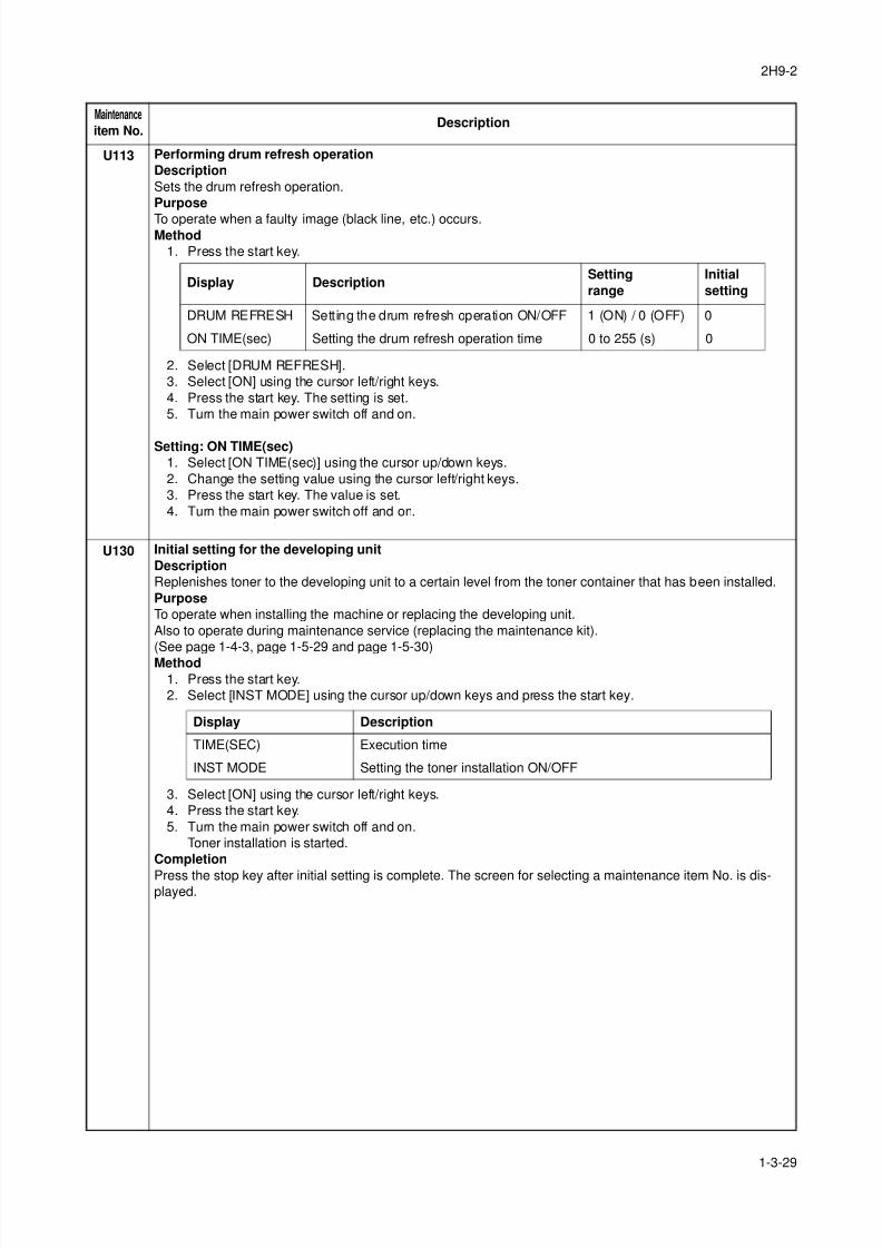
8/3/2019 Servi manualKM-2810ENSMR3
http://slidepdf.com/reader/full/servi-manualkm-2810ensmr3 55/202
2H9-2
1-3-29
U113 Performing drum refresh operation
Description
Sets the drum refresh operation.
Purpose
To operate when a faulty image (black line, etc.) occurs.Method
1. Press the start key.
2. Select [DRUM REFRESH].
3. Select [ON] using the cursor left/right keys.
4. Press the start key. The setting is set.
5. Turn the main power switch off and on.
Setting: ON TIME(sec)
1. Select [ON TIME(sec)] using the cursor up/down keys.
2. Change the setting value using the cursor left/right keys.
3. Press the start key. The value is set.
4. Turn the main power switch off and on.
U130 Initial setting for the developing unit
Description
Replenishes toner to the developing unit to a certain level from the toner container that has been installed.
Purpose
To operate when installing the machine or replacing the developing unit.
Also to operate during maintenance service (replacing the maintenance kit).
(See page 1-4-3, page 1-5-29 and page 1-5-30)
Method
1. Press the start key.
2. Select [INST MODE] using the cursor up/down keys and press the start key.
3. Select [ON] using the cursor left/right keys.
4. Press the start key.
5. Turn the main power switch off and on.
Toner installation is started.
Completion
Press the stop key after initial setting is complete. The screen for selecting a maintenance item No. is dis-played.
Maintenance
item No.Description
Display DescriptionSetting
range
Initial
setting
DRUM REFRESH Setting the drum refresh operation ON/OFF 1 (ON) / 0 (OFF) 0
ON TIME(sec) Setting the drum refresh operation time 0 to 255 (s) 0
Display Description
TIME(SEC) Execution time
INST MODE Setting the toner installation ON/OFF
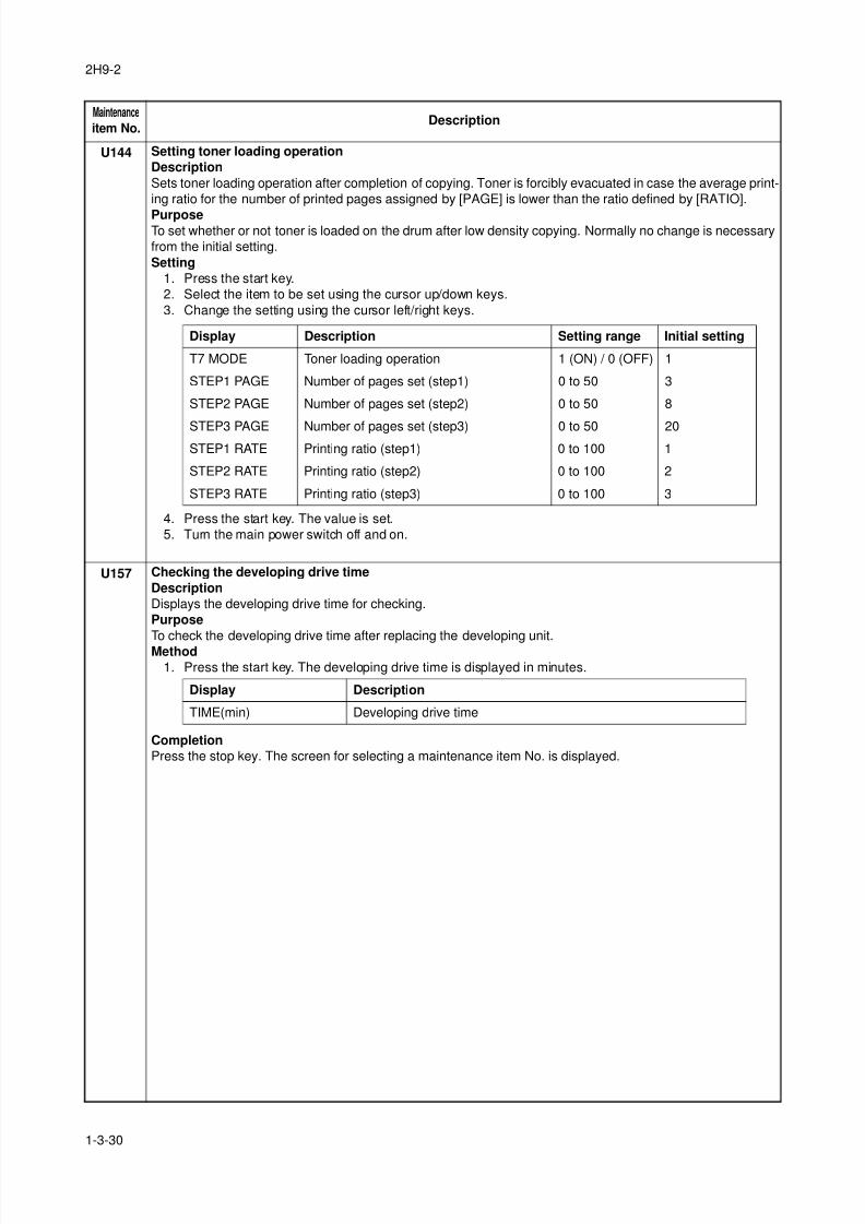
8/3/2019 Servi manualKM-2810ENSMR3
http://slidepdf.com/reader/full/servi-manualkm-2810ensmr3 56/202
2H9-2
1-3-30
U144 Setting toner loading operation
Description
Sets toner loading operation after completion of copying. Toner is forcibly evacuated in case the average print-
ing ratio for the number of printed pages assigned by [PAGE] is lower than the ratio defined by [RATIO].
PurposeTo set whether or not toner is loaded on the drum after low density copying. Normally no change is necessary
from the initial setting.
Setting
1. Press the start key.
2. Select the item to be set using the cursor up/down keys.
3. Change the setting using the cursor left/right keys.
4. Press the start key. The value is set.
5. Turn the main power switch off and on.
U157 Checking the developing drive time
Description
Displays the developing drive time for checking.
Purpose
To check the developing drive time after replacing the developing unit.
Method
1. Press the start key. The developing drive time is displayed in minutes.
Completion
Press the stop key. The screen for selecting a maintenance item No. is displayed.
Maintenance
item No.Description
Display Description Setting range Initial setting
T7 MODE Toner loading operation 1 (ON) / 0 (OFF) 1
STEP1 PAGE Number of pages set (step1) 0 to 50 3
STEP2 PAGE Number of pages set (step2) 0 to 50 8
STEP3 PAGE Number of pages set (step3) 0 to 50 20STEP1 RATE Printing ratio (step1) 0 to 100 1
STEP2 RATE Printing ratio (step2) 0 to 100 2
STEP3 RATE Printing ratio (step3) 0 to 100 3
Display Description
TIME(min) Developing drive time
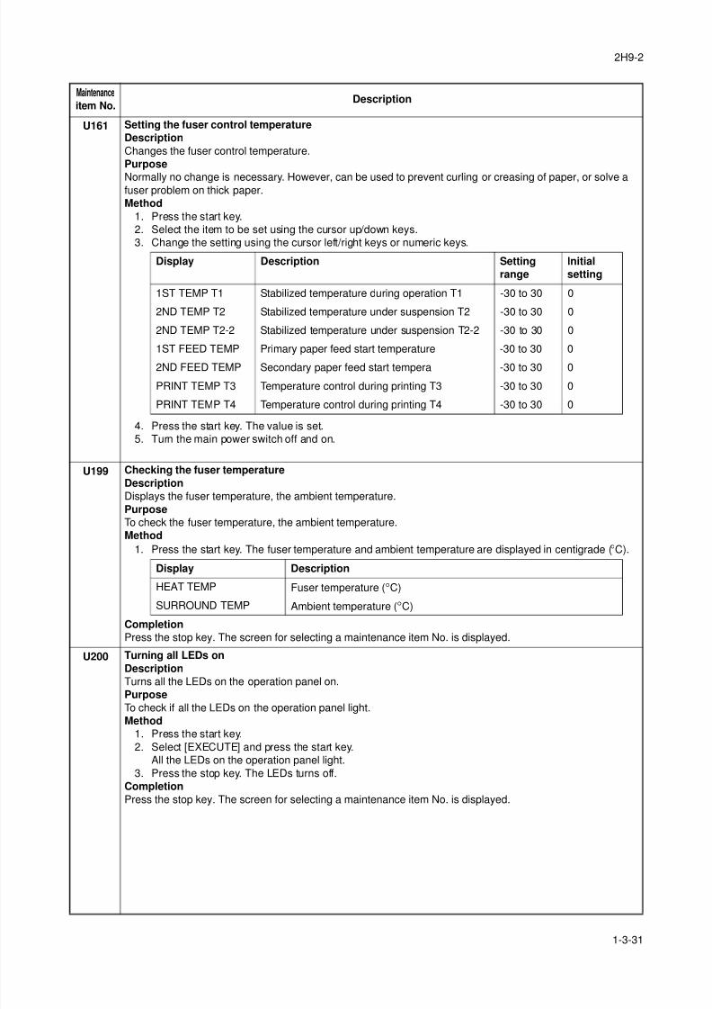
8/3/2019 Servi manualKM-2810ENSMR3
http://slidepdf.com/reader/full/servi-manualkm-2810ensmr3 57/202
2H9-2
1-3-31
U161 Setting the fuser control temperature
Description
Changes the fuser control temperature.
Purpose
Normally no change is necessary. However, can be used to prevent curling or creasing of paper, or solve afuser problem on thick paper.
Method
1. Press the start key.
2. Select the item to be set using the cursor up/down keys.
3. Change the setting using the cursor left/right keys or numeric keys.
4. Press the start key. The value is set.
5. Turn the main power switch off and on.
U199 Checking the fuser temperature
Description
Displays the fuser temperature, the ambient temperature.
Purpose
To check the fuser temperature, the ambient temperature.
Method
1. Press the start key. The fuser temperature and ambient temperature are displayed in centigrade (°C).
Completion
Press the stop key. The screen for selecting a maintenance item No. is displayed.
U200 Turning all LEDs on
Description
Turns all the LEDs on the operation panel on.
Purpose
To check if all the LEDs on the operation panel light.Method
1. Press the start key.
2. Select [EXECUTE] and press the start key.
All the LEDs on the operation panel light.
3. Press the stop key. The LEDs turns off.
Completion
Press the stop key. The screen for selecting a maintenance item No. is displayed.
Maintenance
item No.Description
Display Description Setting
range
Initial
setting
1ST TEMP T1 Stabilized temperature during operation T1 -30 to 30 0
2ND TEMP T2 Stabilized temperature under suspension T2 -30 to 30 0
2ND TEMP T2-2 Stabilized temperature under suspension T2-2 -30 to 30 0
1ST FEED TEMP Primary paper feed start temperature -30 to 30 02ND FEED TEMP Secondary paper feed start tempera -30 to 30 0
PRINT TEMP T3 Temperature control during printing T3 -30 to 30 0
PRINT TEMP T4 Temperature control during printing T4 -30 to 30 0
Display Description
HEAT TEMP Fuser temperature (°C)
SURROUND TEMP Ambient temperature (°C)
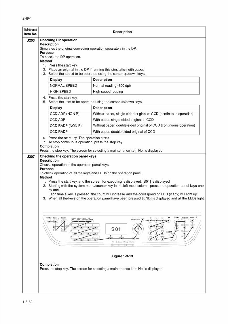
8/3/2019 Servi manualKM-2810ENSMR3
http://slidepdf.com/reader/full/servi-manualkm-2810ensmr3 58/202
2H9-1
1-3-32
U203 Checking DP operation
Description
Simulates the original conveying operation separately in the DP.
Purpose
To check the DP operation.Method
1. Press the start key.
2. Place an original in the DP if running this simulation with paper.
3. Select the speed to be operated using the cursor up/down keys.
4. Press the start key.
5. Select the item to be operated using the cursor up/down keys.
6. Press the start key. The operation starts.
7. To stop continuous operation, press the stop key.
Completion
Press the stop key. The screen for selecting a maintenance item No. is displayed.
U207 Checking the operation panel keys
Description
Checks operation of the operation panel keys.
PurposeTo check operation of all the keys and LEDs on the operation panel.
Method
1. Press the start key. and the screen for executing is displayed. [S01] is displayed
2. Starting with the system menu/counter key in the left most column, press the operation panel keys one
by one.
Each time a key is pressed, the count will increase and the corresponding LED (if any) will light up.
3. When all the keys on the operation panel have been pressed, [END] is displayed and all the LEDs light.
Figure 1-3-13
Completion
Press the stop key. The screen for selecting a maintenance item No. is displayed.
Maintenance
item No.Description
Display Description
NORMAL SPEED Normal reading (600 dpi)
HIGH SPEED High-speed reading
Display Description
CCD ADP (NON P) Without paper, single-sided original of CCD (continuous operation)
CCD ADP With paper, single-sided original of CCD
CCD RADP (NON P) Without paper, double-sided original of CCD (continuous operation)
CCD RADP With paper, double-sided original of CCD
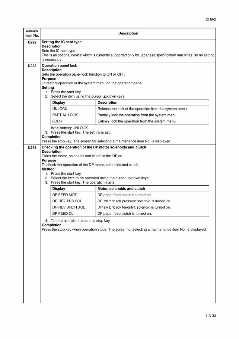
8/3/2019 Servi manualKM-2810ENSMR3
http://slidepdf.com/reader/full/servi-manualkm-2810ensmr3 59/202
2H9-2
1-3-33
U222 Setting the IC card type
Description
Sets the IC card type.
This is an optional device which is currently supported only by Japanese specification machines, so no setting
is necessary.
U223 Operation panel lock
Description
Sets the operation panel lock function to ON or OFF.
Purpose
To restrict operation in the system menu on the operation panel.
Setting
1. Press the start key.
2. Select the item using the cursor up/down keys.
Initial setting: UNLOCK
3. Press the start key. The setting is set.
Completion
Press the stop key. The screen for selecting a maintenance item No. is displayed.
U243 Checking the operation of the DP motor solenoids and clutch
Description
Turns the motor, solenoids and clutch in the DP on.
Purpose
To check the operation of the DP motor, solenoids and clutch.
Method
1. Press the start key.
2. Select the item to be operated using the cursor up/down keys.3. Press the start key. The operation starts.
4. To stop operation, press the stop key.
Completion
Press the stop key when operation stops. The screen for selecting a maintenance item No. is displayed.
Maintenance
item No.Description
Display Description
UNLOCK Release the lock of the operation from the system menu
PARTIAL LOCK Partially lock the operation from the system menu
LOCK Entirely lock the operation from the system menu
Display Motor, solenoids and clutch
DP FEED MOT DP paper feed motor is turned on.
DP REV PRS SOL DP switchback pressure solenoid is turned on.
DP REV BRCH SOL DP switchback feedshift solenoid is turned on.
DP FEED CL DP paper feed clutch is turned on.
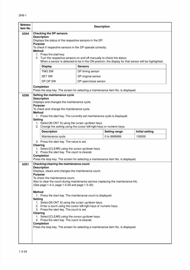
8/3/2019 Servi manualKM-2810ENSMR3
http://slidepdf.com/reader/full/servi-manualkm-2810ensmr3 60/202
2H9-1
1-3-34
U244 Checking the DP sensors
Description
Displays the status of the respective sensors in the DP.
Purpose
To check if respective sensors in the DP operate correctly.Method
1. Press the start key.
2. Turn the respective sensors on and off manually to check the status.
When a sensor is detected to be in the ON posit ion, the display for that sensor will be highlighted.
Completion
Press the stop key. The screen for selecting a maintenance item No. is displayed.
U250 Setting the maintenance cycleDescription
Displays and changes the maintenance cycle.
Purpose
To check and change the maintenance cycle.
Method
1. Press the start key. The currently set maintenance cycle is displayed.
Setting
1. Select [M.CNT A] using the cursor up/down keys.
2. Change the setting using the cursor left/right keys or numeric keys.
3. Press the start key. The value is set.Clearing
1. Select [CLEAR] using the cursor up/down keys.
2. Press the start key. The count is cleared.
Completion
Press the stop key. The screen for selecting a maintenance item No. is displayed.
U251 Checking/clearing the maintenance count
Description
Displays, clears and changes the maintenance count.
Purpose
To check the maintenance count.
Also to clear the count during maintenance service (replacing the maintenance kit).
(See page 1-4-3, page 1-5-29 and page 1-5-30)
Method
1. Press the start key. The maintenance count is displayed.
Setting
1. Select [M.CNT A] using the cursor up/down keys.
2. Enter a count using the cursor left/right keys or numeric keys.
3. Press the start key. The count is set.
Clearing
1. Select [CLEAR] using the cursor up/down keys.
2. Press the start key. The count is cleared.
Completion
Press the stop key. The screen for selecting a maintenance item No. is displayed.
Maintenance
item No.Description
Display Sensors
TMG SW DP timing sensor
SET SW DP original sensor
DP OP SW DP open/close sensor
Description Setting range Initial setting
Maintenance cycle 0 to 9999999 100000
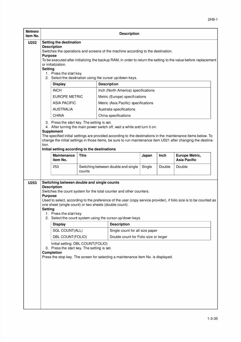
8/3/2019 Servi manualKM-2810ENSMR3
http://slidepdf.com/reader/full/servi-manualkm-2810ensmr3 61/202
2H9-1
1-3-35
U252 Setting the destination
Description
Switches the operations and screens of the machine according to the destination.
Purpose
To be executed after initializing the backup RAM, in order to return the setting to the value before replacementor initialization.
Setting
1. Press the start key.
2. Select the destination using the cursor up/down keys.
3. Press the start key. The setting is set.
4. After turning the main power switch off, wait a while and turn it on.
Supplement
The specified initial settings are provided according to the destinations in the maintenance items below. To
change the initial settings in those items, be sure to run maintenance item U021 after changing the destina-
tion.
Initial setting according to the destinations
U253 Switching between double and single counts
Description
Switches the count system for the total counter and other counters.
Purpose
Used to select, according to the preference of the user (copy service provider), if folio size is to be counted as
one sheet (single count) or two sheets (double count).
Setting
1. Press the start key.
2. Select the count system using the cursor up/down keys.
Initial setting: DBL COUNT(FOLIO)
3. Press the start key. The setting is set.
Completion
Press the stop key. The screen for selecting a maintenance item No. is displayed.
Maintenance
item No.Description
Display Description
INCH Inch (North America) specifications
EUROPE METRIC Metric (Europe) specifications
ASIA PACIFIC Metric (Asia Pacific) specifications
AUSTRALIA Australia specifications
CHINA China specifications
Maintenance
item No.
Title Japan Inch Europe Metric,
Asia Pacific
253 Switching between double and single
counts
Single Double Double
Display Description
SGL COUNT(ALL) Single count for all size paper
DBL COUNT(FOLIO) Double count for Folio size or larger
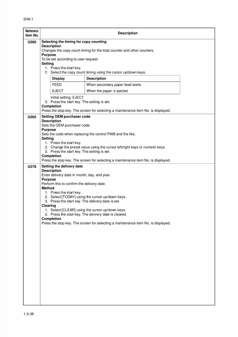
8/3/2019 Servi manualKM-2810ENSMR3
http://slidepdf.com/reader/full/servi-manualkm-2810ensmr3 62/202
2H9-1
1-3-36
U260 Selecting the timing for copy counting
Description
Changes the copy count timing for the total counter and other counters.
Purpose
To be set according to user request.Setting
1. Press the start key.
2. Select the copy count timing using the cursor up/down keys.
Initial setting: EJECT
3. Press the start key. The setting is set.
Completion
Press the stop key. The screen for selecting a maintenance item No. is displayed.
U265 Setting OEM purchaser codeDescription
Sets the OEM purchaser code.
Purpose
Sets the code when replacing the control PWB and the like.
Setting
1. Press the start key.
2. Change the preset value using the cursor left/right keys or numeric keys.
3. Press the start key. The setting is set.
Completion
Press the stop key. The screen for selecting a maintenance item No. is displayed.
U278 Setting the delivery date
Description
Enter delivery date in month, day, and year.
Purpose
Perform this to confirm the delivery date.
Method
1. Press the start key.
2. Select [TODAY] using the cursor up/down keys.
3. Press the start key. The delivery date is set.
Clearing
1. Select [CLEAR] using the cursor up/down keys.
2. Press the start key. The delivery date is cleared.
Completion
Press the stop key. The screen for selecting a maintenance item No. is displayed.
Maintenance
item No.Description
Display Description
FEED When secondary paper feed starts
EJECT When the paper is ejected
8/3/2019 Servi manualKM-2810ENSMR3
http://slidepdf.com/reader/full/servi-manualkm-2810ensmr3 63/202
2H9-1
1-3-37
U285 Setting service status page
Description
Determines displaying the digital dot coverage report on reporting.
Purpose
According to user request, changes the setting.Setting
1. Press the start key.
2. Select ON or OFF using the cursor up/down keys.
Initial setting: ON
3. Press the start key. The setting is set.
Completion
Press the stop key. The screen for selecting a maintenance item No. is displayed.
U332 Setting the size conversion factorSets the coefficient of nonstandard sizes in relation to the A4/Letter size. The coefficient set here is used to
convert the black ratio in relation to the A4/Letter size and to display the result in user simulation.
Purpose
To set the coefficient for converting the black ratio for nonstandard sizes in relation to the A4/Letter size.
Setting
1. Press the start key.
2. Change the setting using the cursor left/right keys or numeric keys.
3. Press the start key. The value is set.
Completion
Press the stop key. The screen for selecting a maintenance item No. is displayed.
U342 Setting the ejection restriction
Description
Sets or cancels the restriction on the number of sheets to be ejected continuously.
Purpose
According to user request, sets or cancels restriction on the number of sheets.
Setting
1. Press the start key.
2. Select [ON] or [OFF] using the cursor up/down keys.
Initial setting: ON
3. Press the start key. The setting is set.
Completion
Press the stop key. The screen for selecting a maintenance item No. is displayed.
Maintenance
item No.Description
Display Description
ON Displays the digital dot coverage
OFF Not to display the digital dot coverage
Display Description Setting range Initial setting
Calc. Rate Size parameter 0.1 to 3.0 1.0
Display Description
ON Sets restriction on the number of sheets
OFF Cancels restriction on the number of sheets
8/3/2019 Servi manualKM-2810ENSMR3
http://slidepdf.com/reader/full/servi-manualkm-2810ensmr3 64/202
2H9-1
1-3-38
U343 Switching between duplex/simplex copy mode
Description
Switches the initial setting between duplex and simplex copy.
Purpose
To be set according to frequency of use: set to the more frequently used mode.Setting
1. Press the start key.
2. Select [ON] or [OFF] using the cursor up/down keys.
Initial setting: OFF
3. Press the start key. The setting is set.
Completion
Press the stop key. The screen for selecting a maintenance item No. is displayed.
U345 Setting the value for maintenance due indicationDescriptionSets when to display a message notifying that the time for maintenance is about to be reached, by setting thenumber of copies that can be made before the current maintenance cycle ends.When the difference between the number of copies of the maintenance cycle and that of the maintenancecount reaches the set value, the message is displayed.Purpose
To change the time for maintenance due indication.
Setting
1. Press the start key.
2. Select [COUNT] using the cursor up/down keys.
3. Change the setting using the cursor left/right keys.
Initial setting: 0
4. Press the start key. The value is set.
Completion
Press the stop key. The screen for selecting a maintenance item No. is displayed.
Maintenance
item No.Description
Display Description
ON Duplex copy
OFF Simplex copy
Display Description Setting range
COUNT Time for maintenance due indication
(Remaining number of copies that can be made before the
current maintenance cycle ends)
0 to 9999
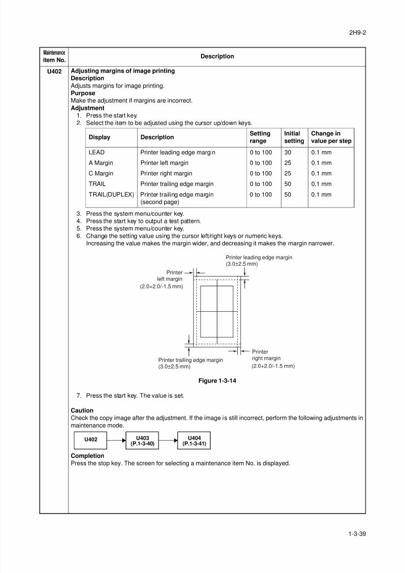
8/3/2019 Servi manualKM-2810ENSMR3
http://slidepdf.com/reader/full/servi-manualkm-2810ensmr3 65/202
2H9-2
1-3-39
U402 Adjusting margins of image printing
Description
Adjusts margins for image printing.
Purpose
Make the adjustment if margins are incorrect.Adjustment
1. Press the start key.
2. Select the item to be adjusted using the cursor up/down keys.
3. Press the system menu/counter key.
4. Press the start key to output a test pattern.
5. Press the system menu/counter key.
6. Change the setting value using the cursor left/right keys or numeric keys.
Increasing the value makes the margin wider, and decreasing it makes the margin narrower.
Figure 1-3-14
7. Press the start key. The value is set.
Caution
Check the copy image after the adjustment. If the image is still incorrect, perform the following adjustments in
maintenance mode.
Completion
Press the stop key. The screen for selecting a maintenance item No. is displayed.
Maintenance
item No.Description
Display DescriptionSetting
range
Initial
setting
Change in
value per step
LEAD Printer leading edge margin 0 to 100 30 0.1 mm
A Margin Printer left margin 0 to 100 25 0.1 mm
C Margin Printer right margin 0 to 100 25 0.1 mm
TRAIL Printer trailing edge margin 0 to 100 50 0.1 mm
TRAIL(DUPLEX) Printer trailing edge margin
(second page)
0 to 100 50 0.1 mm
(2.0+2.0/-1.5 mm)
(2.0+2.0/-1.5 mm)
Printer leading edge margin(3.0±2.5 mm)
Printerleft margin
Printerright marginPrinter trailing edge margin
(3.0±2.5 mm)
U402 U403(P.1-3-40)
U404(P.1-3-41)
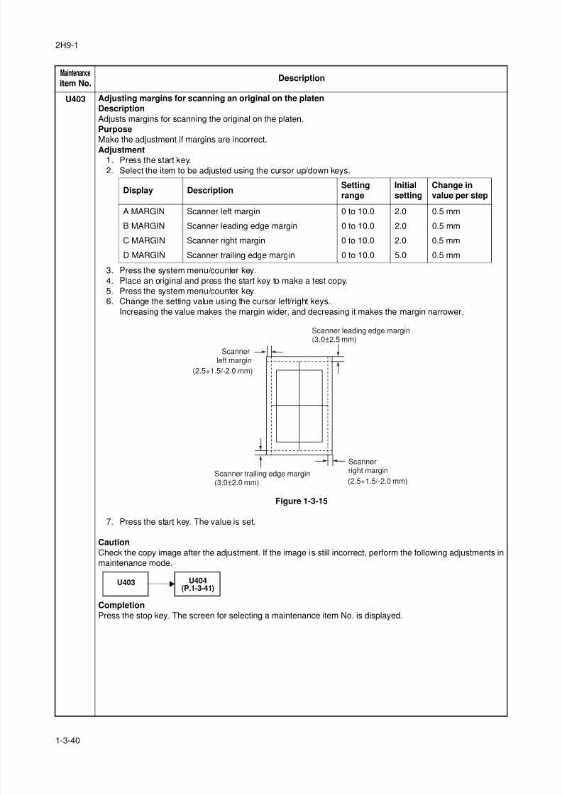
8/3/2019 Servi manualKM-2810ENSMR3
http://slidepdf.com/reader/full/servi-manualkm-2810ensmr3 66/202
2H9-1
1-3-40
U403 Adjusting margins for scanning an original on the platen
Description
Adjusts margins for scanning the original on the platen.
Purpose
Make the adjustment if margins are incorrect.Adjustment
1. Press the start key.
2. Select the item to be adjusted using the cursor up/down keys.
3. Press the system menu/counter key.
4. Place an original and press the start key to make a test copy.5. Press the system menu/counter key.
6. Change the setting value using the cursor left/right keys.
Increasing the value makes the margin wider, and decreasing it makes the margin narrower.
Figure 1-3-15
7. Press the start key. The value is set.
Caution
Check the copy image after the adjustment. If the image is still incorrect, perform the following adjustments inmaintenance mode.
Completion
Press the stop key. The screen for selecting a maintenance item No. is displayed.
Maintenance
item No.Description
Display DescriptionSetting
range
Initial
setting
Change in
value per step
A MARGIN Scanner left margin 0 to 10.0 2.0 0.5 mm
B MARGIN Scanner leading edge margin 0 to 10.0 2.0 0.5 mm
C MARGIN Scanner right margin 0 to 10.0 2.0 0.5 mm
D MARGIN Scanner trailing edge margin 0 to 10.0 5.0 0.5 mm
(2.5+1.5/-2.0 mm)
(2.5+1.5/-2.0 mm)
Scanner leading edge margin(3.0±2.5 mm)
Scannerleft margin
Scannerright marginScanner trailing edge margin
(3.0±2.0 mm)
U403 U404(P.1-3-41)
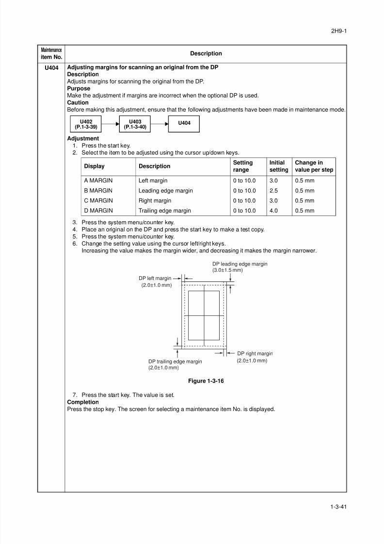
8/3/2019 Servi manualKM-2810ENSMR3
http://slidepdf.com/reader/full/servi-manualkm-2810ensmr3 67/202
2H9-1
1-3-41
U404 Adjusting margins for scanning an original from the DP
Description
Adjusts margins for scanning the original from the DP.
Purpose
Make the adjustment if margins are incorrect when the optional DP is used.Caution
Before making this adjustment, ensure that the following adjustments have been made in maintenance mode.
Adjustment
1. Press the start key.
2. Select the item to be adjusted using the cursor up/down keys.
3. Press the system menu/counter key.
4. Place an original on the DP and press the start key to make a test copy.
5. Press the system menu/counter key.
6. Change the setting value using the cursor left/right keys.
Increasing the value makes the margin wider, and decreasing it makes the margin narrower.
Figure 1-3-16
7. Press the start key. The value is set.
Completion
Press the stop key. The screen for selecting a maintenance item No. is displayed.
Maintenance
item No.Description
U403(P.1-3-40)
U402(P.1-3-39)
U404
Display DescriptionSetting
range
Initial
setting
Change in
value per step
A MARGIN Left margin 0 to 10.0 3.0 0.5 mm
B MARGIN Leading edge margin 0 to 10.0 2.5 0.5 mm
C MARGIN Right margin 0 to 10.0 3.0 0.5 mm
D MARGIN Trailing edge margin 0 to 10.0 4.0 0.5 mm
(2.0±1.0 mm)
(2.0±1.0 mm)
DP leading edge margin(3.0±1.5 mm)
DP left margin
DP right margin
DP trailing edge margin(2.0±1.0 mm)
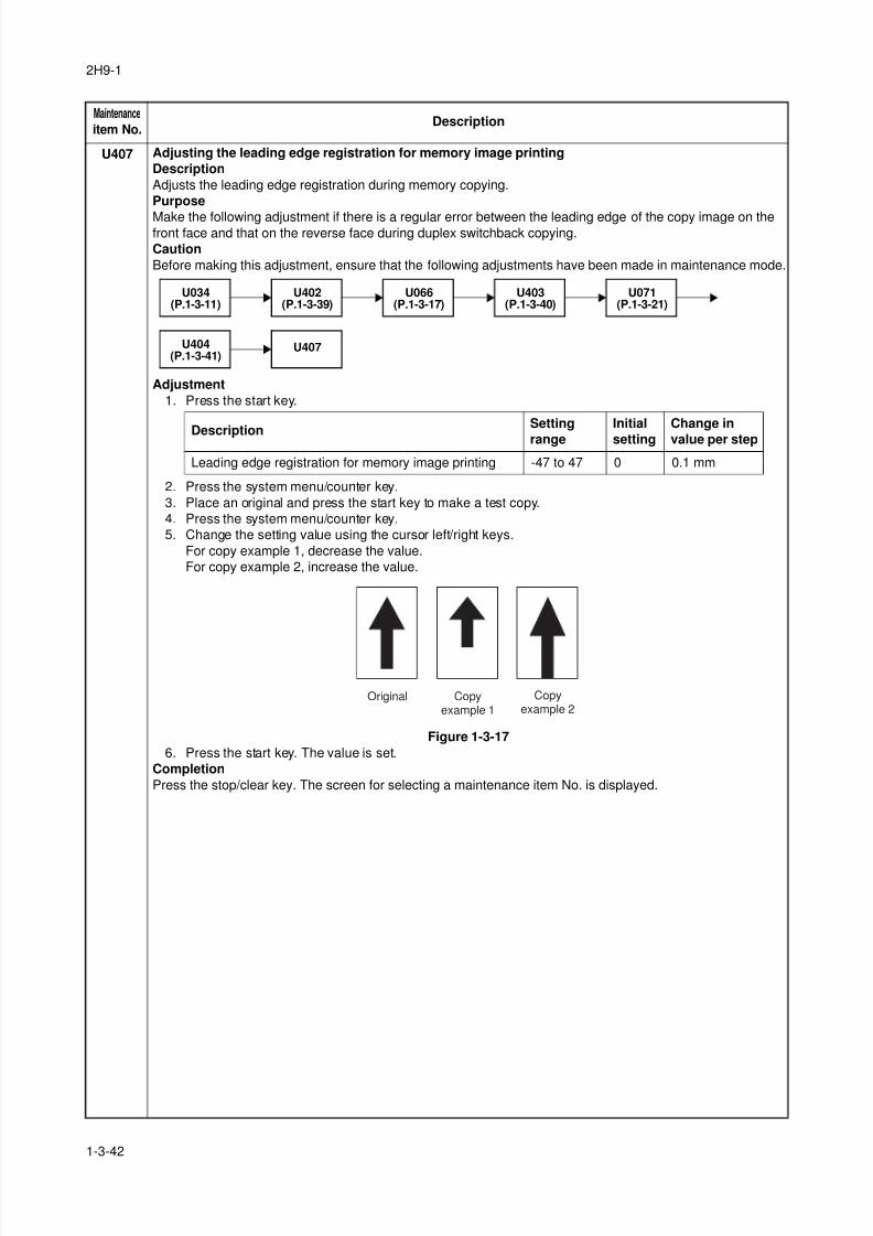
8/3/2019 Servi manualKM-2810ENSMR3
http://slidepdf.com/reader/full/servi-manualkm-2810ensmr3 68/202
2H9-1
1-3-42
U407 Adjusting the leading edge registration for memory image printing
Description
Adjusts the leading edge registration during memory copying.
Purpose
Make the following adjustment if there is a regular error between the leading edge of the copy image on thefront face and that on the reverse face during duplex switchback copying.
Caution
Before making this adjustment, ensure that the following adjustments have been made in maintenance mode.
Adjustment
1. Press the start key.
2. Press the system menu/counter key.
3. Place an original and press the start key to make a test copy.
4. Press the system menu/counter key.
5. Change the setting value using the cursor left/right keys.
For copy example 1, decrease the value.
For copy example 2, increase the value.
Figure 1-3-17
6. Press the start key. The value is set.
Completion
Press the stop/clear key. The screen for selecting a maintenance item No. is displayed.
Maintenance
item No.Description
U402(P.1-3-39)
U034(P.1-3-11)
U066(P.1-3-17)
U403(P.1-3-40)
U071(P.1-3-21)
U407U404(P.1-3-41)
DescriptionSetting
range
Initial
setting
Change in
value per step
Leading edge registration for memory image printing -47 to 47 0 0.1 mm
Original Copyexample 1
Copyexample 2
8/3/2019 Servi manualKM-2810ENSMR3
http://slidepdf.com/reader/full/servi-manualkm-2810ensmr3 69/202
2H9-1
1-3-43
U411 Adjusting the scanner automatically
Description
Uses the adjustment original suppled with DP and automatically adjusts the following items in the scanner and
the DP scanning sections.
PurposeTo perform automatic adjustment of various items in the scanner and the DP scanning sections.
Method
1. Press the start key.
Method: TABLE
1. Enter the target values which are shown on the specified original (P/N: 302FZ56990) executing mainte-
nance item U425.
2. Set a specified original (P/N: 302FZ56990) on the platen.
3. Enter maintenance item U411.
4. Select [ADJUST TABLE] using the cursor up/down keys.
5. Press the start key. Auto adjustment starts.
When automatic adjustment has normally completed, [OK] is displayed. If a problem occurs during auto
adjustment, [NG XX] (XX is replaced by an error code) is displayed and operation stops. Should this
happen, determine the details of the problem and either repeat the procedure from the beginning, or
adjust the remaining items manually by running the corresponding maintenance items.
6. To return to the screen for selecting an item, press the stop key.
Method: DP
1. Select [ADJUST DP] using the cursor up/down keys.
2. Set a specified original (P/N: 303LJ57010) in the DP.
3. Press the start key. Auto adjustment starts.
When automatic adjustment has normally completed, [OK] is displayed. If a problem occurs during auto
adjustment, [NG XX] (XX is replaced by an error code) is displayed and operation stops. Should this
happen, determine the details of the problem and either repeat the procedure from the beginning, or
adjust the remaining items manually by running the corresponding maintenance items.
4. To return to the screen for selecting an item, press the stop key.
Completion
Press the stop key. The screen for selecting a maintenance item is displayed.
Maintenance
item No.Description
Display Description Original to be used
for adjustment (P/N)
ADJUST TABLE Automatic adjustment in the scanner section:
Original size magnification, leading edge timing,
center line, input gamma, input gamma in mono-
chrome mode and matrix
302FZ56990
ADJUST DP Automatic adjustment in the DP scanning section:
Original size magnification, leading edge timing,
center line
303LJ57010
(Adjustment original
suppled with DP)
8/3/2019 Servi manualKM-2810ENSMR3
http://slidepdf.com/reader/full/servi-manualkm-2810ensmr3 70/202
2H9-1
1-3-44
U425 Setting the target
Description
Enters the lab values that is indicated on the back of the chart (P/N: 302FZ56990) used for adjustment.
Purpose
Performs data input in order to correct for differences in originals during automatic adjustment.Method
1. Press the start key.
2. Select the item to be set using the cursor up/down keys.
3. Select the item to be set using the cursor up/down keys.
4. Enters the value that is indicated on the back of the chart using the cursor left/right keys or numeric
keys.
5. Press the start key. The value is set.
6. To return to the screen for selecting an item, press the stop key.
Setting: [ADJUST ORIGINAL]
1. Measure the distance from the left edge to the black belt (a) of the original at A, B and C.
Measurement procedure
1) Measure the distance from the edge to the black belt (a) of the original at A (30 mm from the leading
edge), B (148.5 mm from the leading edge) and C (267 mm from the leading edge), respectively.
2) Apply the following formula for the values obtained: ((A + C) / 2 + B) / 2
2. Enter the values solved using the cursor left/right keys or numeric keys in [MAIN].
3. Press the start key. The value is set.
4. Measure the distance from the leading edge to the black belt (b) of the original at D, E and F.Measurement procedure
1) Measure the distance from the edge to the black belt (b) of the original at D (35 mm from the left
edge), E (110 mm from the left edge) and F (185 mm from the left edge), respectively.
2) Apply the following formula for the values obtained: ((D + F) / 2 + E) / 2
5. Enter the values solved using the cursor left/right keys or numeric keys in [SUB LEAD].
6. Press the start key. The value is set.
7. Measure the length (G) from the edge of the black belt (b) to edge of the black belt (c) of the original.
8. Enter the measured value using the cursor left/right keys or numeric keys in [SUB TAIL].
9. Press the start key. The value is set.
10. To return to the screen for selecting an item, press the stop key.
Maintenance
item No.Description
Display Description
N875 Setting the N875 patch for the original for adjustment
N475 Setting the N475 patch for the original for adjustment
N125 Setting the N125 patch for the original for adjustment
CYAN Setting the cyan patch for the original for adjustment
MAGENTA Setting the magenta patch for the original for adjustment
YELLOW Setting the yellow patch for the original for adjustment
RED Setting the red patch for the original for adjustment
GREEN Setting the green patch for the original for adjustment
BLUE Setting the blue patch for the original for adjustment
ADJUST ORIGINAL Setting the main and auxiliary scanning directions
Display Description Setting range
L Setting the L value 0.0 to 100.0
a Setting the a value -200.0 to 200.0
b Setting the b value -200.0 to 200.0
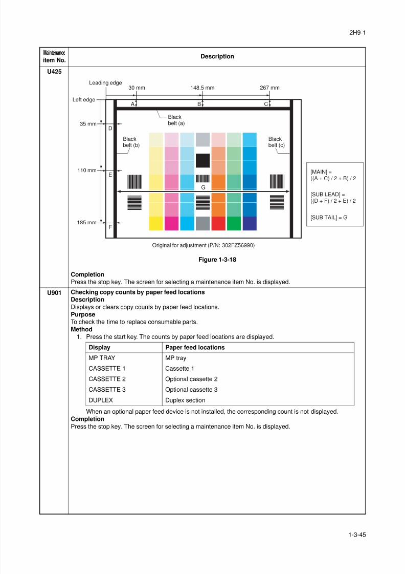
8/3/2019 Servi manualKM-2810ENSMR3
http://slidepdf.com/reader/full/servi-manualkm-2810ensmr3 71/202
2H9-1
1-3-45
U425
Figure 1-3-18
Completion
Press the stop key. The screen for selecting a maintenance item No. is displayed.
U901 Checking copy counts by paper feed locations
DescriptionDisplays or clears copy counts by paper feed locations.
Purpose
To check the time to replace consumable parts.
Method
1. Press the start key. The counts by paper feed locations are displayed.
When an optional paper feed device is not installed, the corresponding count is not displayed.
Completion
Press the stop key. The screen for selecting a maintenance item No. is displayed.
Maintenance
item No.Description
30 mm
D
A C
E
F
35 mm
Leading edge
Left edge
Blackbelt (b)
Blackbelt (a)
110 mm
185 mm
148.5 mm 267 mm
Original for adjustment (P/N: 302FZ56990)
B
Blackbelt (c)
G
[MAIN] =((A + C) / 2 + B) / 2
[SUB LEAD] =
((D + F) / 2 + E) / 2
[SUB TAIL] = G
Display Paper feed locations
MP TRAY MP tray
CASSETTE 1 Cassette 1
CASSETTE 2 Optional cassette 2
CASSETTE 3 Optional cassette 3
DUPLEX Duplex section
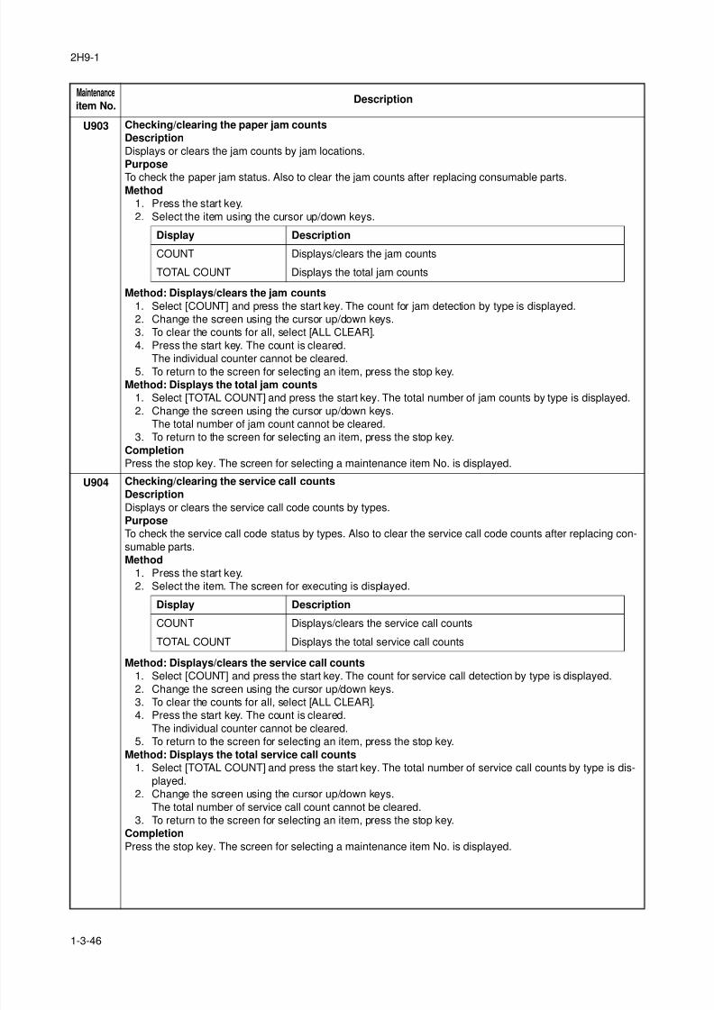
8/3/2019 Servi manualKM-2810ENSMR3
http://slidepdf.com/reader/full/servi-manualkm-2810ensmr3 72/202
2H9-1
1-3-46
U903 Checking/clearing the paper jam counts
Description
Displays or clears the jam counts by jam locations.
Purpose
To check the paper jam status. Also to clear the jam counts after replacing consumable parts.Method
1. Press the start key.
2. Select the item using the cursor up/down keys.
Method: Displays/clears the jam counts
1. Select [COUNT] and press the start key. The count for jam detection by type is displayed.
2. Change the screen using the cursor up/down keys.
3. To clear the counts for all, select [ALL CLEAR].
4. Press the start key. The count is cleared.
The individual counter cannot be cleared.
5. To return to the screen for selecting an item, press the stop key.
Method: Displays the total jam counts
1. Select [TOTAL COUNT] and press the start key. The total number of jam counts by type is displayed.
2. Change the screen using the cursor up/down keys.
The total number of jam count cannot be cleared.
3. To return to the screen for selecting an item, press the stop key.
Completion
Press the stop key. The screen for selecting a maintenance item No. is displayed.
U904 Checking/clearing the service call counts
Description
Displays or clears the service call code counts by types.
Purpose
To check the service call code status by types. Also to clear the service call code counts after replacing con-sumable parts.
Method
1. Press the start key.
2. Select the item. The screen for executing is displayed.
Method: Displays/clears the service call counts
1. Select [COUNT] and press the start key. The count for service call detection by type is displayed.
2. Change the screen using the cursor up/down keys.
3. To clear the counts for all, select [ALL CLEAR].4. Press the start key. The count is cleared.
The individual counter cannot be cleared.
5. To return to the screen for selecting an item, press the stop key.
Method: Displays the total service call counts
1. Select [TOTAL COUNT] and press the start key. The total number of service call counts by type is dis-
played.
2. Change the screen using the cursor up/down keys.
The total number of service call count cannot be cleared.
3. To return to the screen for selecting an item, press the stop key.
Completion
Press the stop key. The screen for selecting a maintenance item No. is displayed.
Maintenance
item No.Description
Display Description
COUNT Displays/clears the jam counts
TOTAL COUNT Displays the total jam counts
Display Description
COUNT Displays/clears the service call counts
TOTAL COUNT Displays the total service call counts
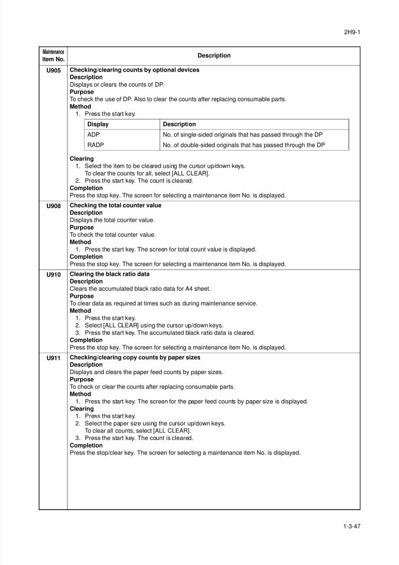
8/3/2019 Servi manualKM-2810ENSMR3
http://slidepdf.com/reader/full/servi-manualkm-2810ensmr3 73/202
2H9-1
1-3-47
U905 Checking/clearing counts by optional devices
Description
Displays or clears the counts of DP.
Purpose
To check the use of DP. Also to clear the counts after replacing consumable parts.Method
1. Press the start key.
Clearing
1. Select the item to be cleared using the cursor up/down keys.
To clear the counts for all, select [ALL CLEAR].
2. Press the start key. The count is cleared.
Completion
Press the stop key. The screen for selecting a maintenance item No. is displayed.U908 Checking the total counter value
Description
Displays the total counter value.
Purpose
To check the total counter value.
Method
1. Press the start key. The screen for total count value is displayed.
Completion
Press the stop key. The screen for selecting a maintenance item No. is displayed.
U910 Clearing the black ratio data
Description
Clears the accumulated black ratio data for A4 sheet.
PurposeTo clear data as required at times such as during maintenance service.
Method
1. Press the start key.
2. Select [ALL CLEAR] using the cursor up/down keys.
3. Press the start key. The accumulated black ratio data is cleared.
Completion
Press the stop key. The screen for selecting a maintenance item No. is displayed.
U911 Checking/clearing copy counts by paper sizes
Description
Displays and clears the paper feed counts by paper sizes.
Purpose
To check or clear the counts after replacing consumable parts.
Method1. Press the start key. The screen for the paper feed counts by paper size is displayed.
Clearing
1. Press the start key.
2. Select the paper size using the cursor up/down keys.
To clear all counts, select [ALL CLEAR].
3. Press the start key. The count is cleared.
Completion
Press the stop/clear key. The screen for selecting a maintenance item No. is displayed.
Maintenance
item No.Description
Display Description
ADP No. of single-sided originals that has passed through the DP
RADP No. of double-sided originals that has passed through the DP
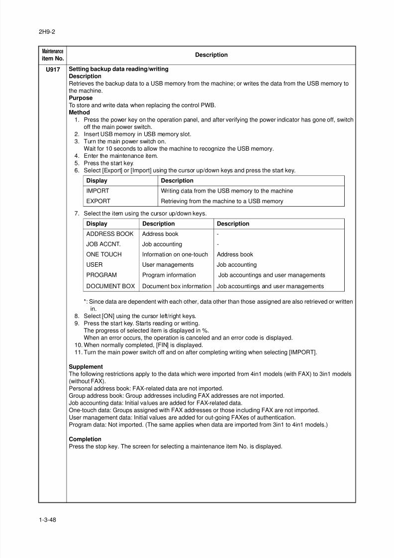
8/3/2019 Servi manualKM-2810ENSMR3
http://slidepdf.com/reader/full/servi-manualkm-2810ensmr3 74/202
2H9-2
1-3-48
U917 Setting backup data reading/writing
Description
Retrieves the backup data to a USB memory from the machine; or writes the data from the USB memory to
the machine.
PurposeTo store and write data when replacing the control PWB.
Method
1. Press the power key on the operation panel, and after verifying the power indicator has gone off, switch
off the main power switch.
2. Insert USB memory in USB memory slot.
3. Turn the main power switch on.
Wait for 10 seconds to allow the machine to recognize the USB memory.
4. Enter the maintenance item.
5. Press the start key.
6. Select [Export] or [Import] using the cursor up/down keys and press the start key.
7. Select the item using the cursor up/down keys.
*: Since data are dependent with each other, data other than those assigned are also retrieved or written
in.
8. Select [ON] using the cursor left/right keys.
9. Press the start key. Starts reading or writing.
The progress of selected item is displayed in %.
When an error occurs, the operation is canceled and an error code is displayed.
10. When normally completed, [FIN] is displayed.
11. Turn the main power switch off and on after completing writing when selecting [IMPORT].
Supplement
The following restrictions apply to the data which were imported from 4in1 models (with FAX) to 3in1 models
(without FAX).
Personal address book: FAX-related data are not imported.Group address book: Group addresses including FAX addresses are not imported.
Job accounting data: Initial values are added for FAX-related data.
One-touch data: Groups assigned with FAX addresses or those including FAX are not imported.
User management data: Initial values are added for out-going FAXes of authentication.
Program data: Not imported. (The same applies when data are imported from 3in1 to 4in1 models.)
Completion
Press the stop key. The screen for selecting a maintenance item No. is displayed.
Maintenance
item No.Description
Display Description
IMPORT Writing data from the USB memory to the machine
EXPORT Retrieving from the machine to a USB memory
Display Description Description
ADDRESS BOOK Address book -
JOB ACCNT. Job accounting -
ONE TOUCH Information on one-touch Address book
USER User managements Job accounting
PROGRAM Program information Job accountings and user managements
DOCUMENT BOX Document box information Job accountings and user managements
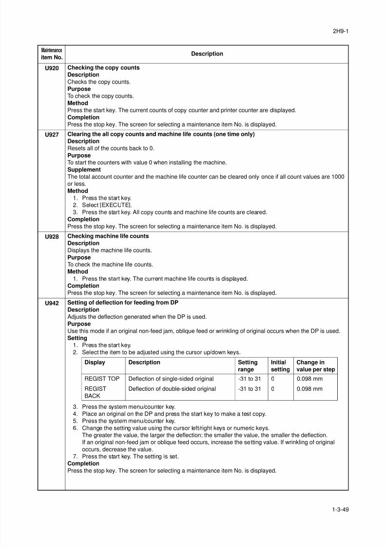
8/3/2019 Servi manualKM-2810ENSMR3
http://slidepdf.com/reader/full/servi-manualkm-2810ensmr3 75/202
2H9-1
1-3-49
U920 Checking the copy counts
Description
Checks the copy counts.
Purpose
To check the copy counts.Method
Press the start key. The current counts of copy counter and printer counter are displayed.
Completion
Press the stop key. The screen for selecting a maintenance item No. is displayed.
U927 Clearing the all copy counts and machine life counts (one time only)
Description
Resets all of the counts back to 0.
Purpose
To start the counters with value 0 when installing the machine.
Supplement
The total account counter and the machine life counter can be cleared only once if all count values are 1000
or less.
Method1. Press the start key.
2. Select [EXECUTE].
3. Press the start key. All copy counts and machine life counts are cleared.
Completion
Press the stop key. The screen for selecting a maintenance item No. is displayed.
U928 Checking machine life counts
Description
Displays the machine life counts.
Purpose
To check the machine life counts.
Method
1. Press the start key. The current machine life counts is displayed.
CompletionPress the stop key. The screen for selecting a maintenance item No. is displayed.
U942 Setting of deflection for feeding from DP
Description
Adjusts the deflection generated when the DP is used.
Purpose
Use this mode if an original non-feed jam, oblique feed or wrinkling of original occurs when the DP is used.
Setting
1. Press the start key.
2. Select the item to be adjusted using the cursor up/down keys.
3. Press the system menu/counter key.
4. Place an original on the DP and press the start key to make a test copy.
5. Press the system menu/counter key.
6. Change the setting value using the cursor left/right keys or numeric keys.
The greater the value, the larger the deflection; the smaller the value, the smaller the deflection.
If an original non-feed jam or oblique feed occurs, increase the setting value. If wrinkling of original
occurs, decrease the value.
7. Press the start key. The setting is set.
Completion
Press the stop key. The screen for selecting a maintenance item No. is displayed.
Maintenance
item No.Description
Display Description Setting
range
Initial
setting
Change in
value per step
REGIST TOP Deflection of single-sided original -31 to 31 0 0.098 mm
REGIST
BACK
Deflection of double-sided original -31 to 31 0 0.098 mm
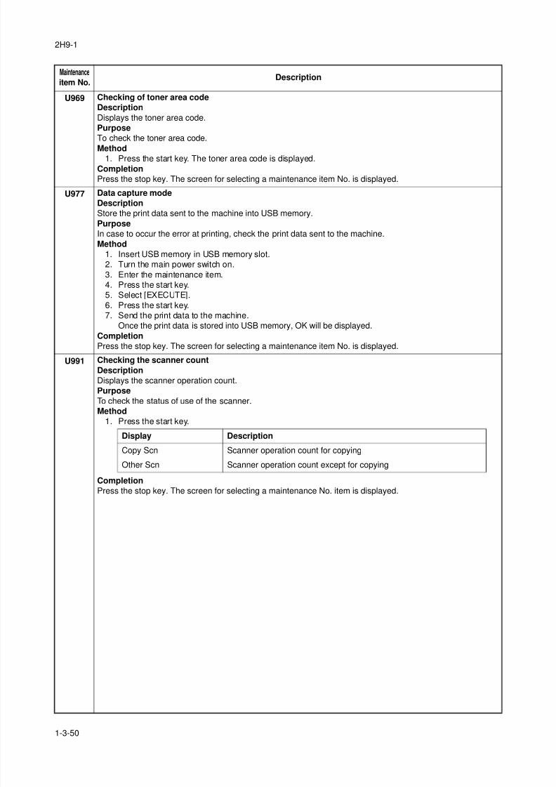
8/3/2019 Servi manualKM-2810ENSMR3
http://slidepdf.com/reader/full/servi-manualkm-2810ensmr3 76/202
2H9-1
1-3-50
U969 Checking of toner area code
Description
Displays the toner area code.
Purpose
To check the toner area code.Method
1. Press the start key. The toner area code is displayed.
Completion
Press the stop key. The screen for selecting a maintenance item No. is displayed.
U977 Data capture mode
Description
Store the print data sent to the machine into USB memory.
Purpose
In case to occur the error at printing, check the print data sent to the machine.
Method
1. Insert USB memory in USB memory slot.
2. Turn the main power switch on.
3. Enter the maintenance item.4. Press the start key.
5. Select [EXECUTE].
6. Press the start key.
7. Send the print data to the machine.
Once the print data is stored into USB memory, OK will be displayed.
Completion
Press the stop key. The screen for selecting a maintenance item No. is displayed.
U991 Checking the scanner count
Description
Displays the scanner operation count.
Purpose
To check the status of use of the scanner.
Method1. Press the start key.
Completion
Press the stop key. The screen for selecting a maintenance No. item is displayed.
Maintenance
item No.Description
Display Description
Copy Scn Scanner operation count for copying
Other Scn Scanner operation count except for copying
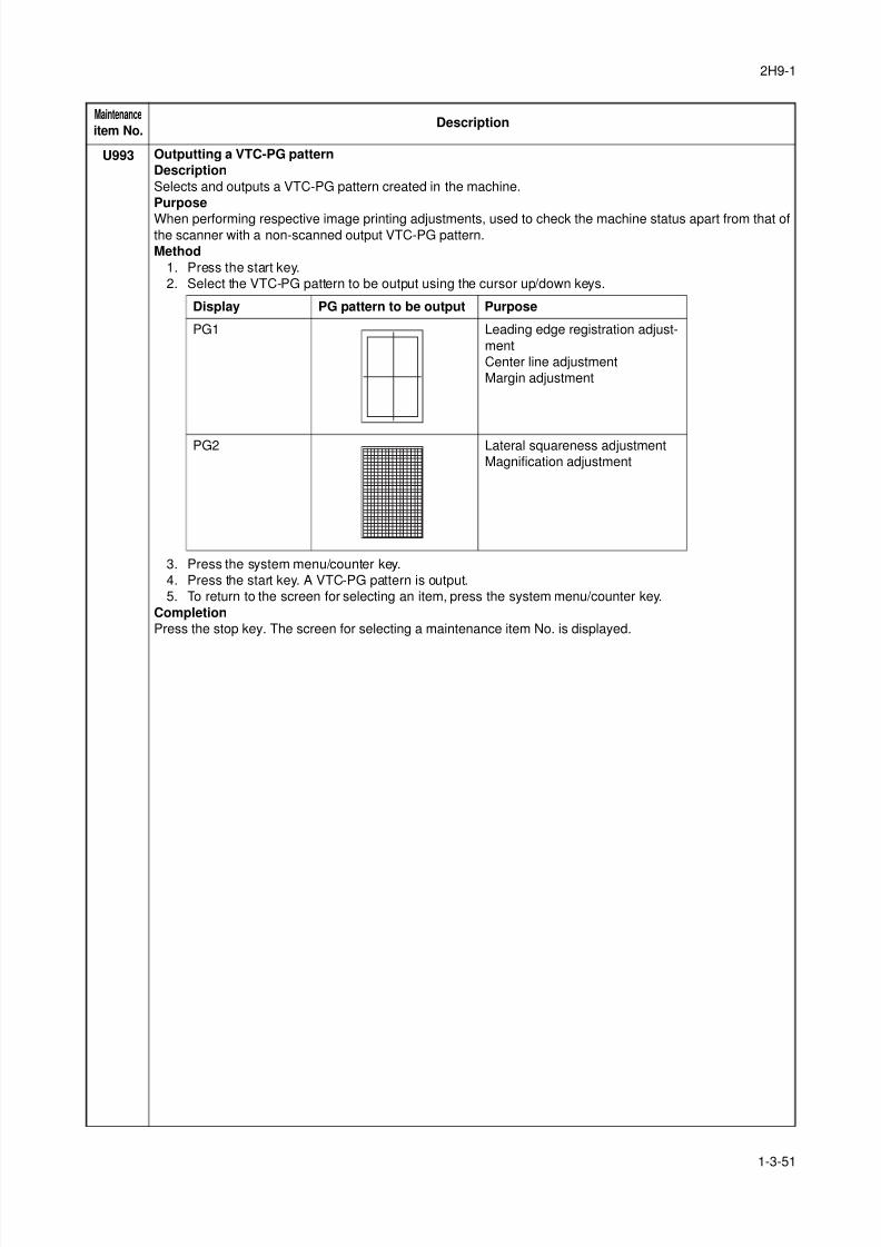
8/3/2019 Servi manualKM-2810ENSMR3
http://slidepdf.com/reader/full/servi-manualkm-2810ensmr3 77/202
2H9-1
1-3-51
U993 Outputting a VTC-PG pattern
Description
Selects and outputs a VTC-PG pattern created in the machine.
Purpose
When performing respective image printing adjustments, used to check the machine status apart from that ofthe scanner with a non-scanned output VTC-PG pattern.
Method
1. Press the start key.
2. Select the VTC-PG pattern to be output using the cursor up/down keys.
3. Press the system menu/counter key.
4. Press the start key. A VTC-PG pattern is output.
5. To return to the screen for selecting an item, press the system menu/counter key.
Completion
Press the stop key. The screen for selecting a maintenance item No. is displayed.
Maintenance
item No.Description
Display PG pattern to be output Purpose
PG1 Leading edge registration adjust-
ment
Center line adjustment
Margin adjustment
PG2 Lateral squareness adjustment
Magnification adjustment
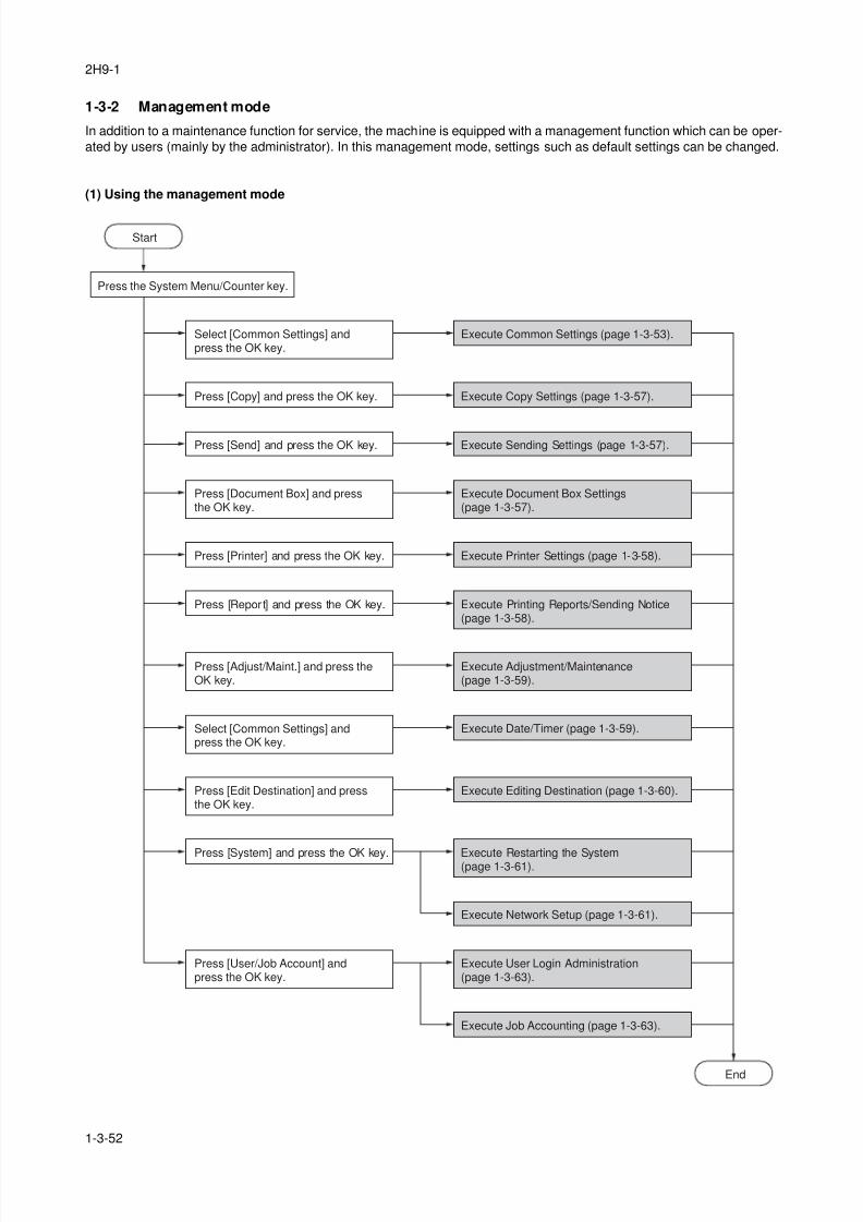
8/3/2019 Servi manualKM-2810ENSMR3
http://slidepdf.com/reader/full/servi-manualkm-2810ensmr3 78/202
2H9-1
1-3-52
1-3-2 Management mode
In addition to a maintenance function for service, the machine is equipped with a management function which can be oper-
ated by users (mainly by the administrator). In this management mode, settings such as default settings can be changed.
(1) Using the management mode
End
Press the System Menu/Counter key.
Select [Common Settings] andpress the OK key.
Select [Common Settings] andpress the OK key.
Execute Common Settings (page 1-3-53).
Press [Copy] and press the OK key. Execute Copy Settings (page 1-3-57).
Press [Send] and press the OK key. Execute Sending Settings (page 1-3-57).
Press [Document Box] and pressthe OK key.
Execute Document Box Settings(page 1-3-57).
Press [Printer] and press the OK key. Execute Printer Settings (page 1-3-58).
Press [Report] and press the OK key. Execute Printing Reports/Sending Notice(page 1-3-58).
Press [Adjust/Maint.] and press theOK key.
Execute Adjustment/Maintenance(page 1-3-59).
Execute Date/Timer (page 1-3-59).
Press [Edit Destination] and pressthe OK key.
Execute Editing Destination (page 1-3-60).
Press [System] and press the OK key. Execute Restarting the System(page 1-3-61).
Execute Network Setup (page 1-3-61).
Press [User/Job Account] andpress the OK key.
Execute User Login Administration(page 1-3-63).
Execute Job Accounting (page 1-3-63).
Start

8/3/2019 Servi manualKM-2810ENSMR3
http://slidepdf.com/reader/full/servi-manualkm-2810ensmr3 79/202
2H9-1
1-3-53
(2) Common Settings
Switching the Language for Display [Language]
1. Select [Language] using the cursor up/down keys.
2. Press the OK key.
3. Select the language you want to use.
4. Press the OK key.
Default Screen
1. Select [Default Screen] using the cursor up/down
keys.
2. Press the OK key.
3. Select the screen to be displayed as the default
screen.
4. Press the OK key.
Sound
1. Select [Sound] using the cursor up/down keys.
2. Press the OK key.3. Select [Buzzer] using the cursor up/down keys.
4. Press the OK key.
5. Select [Key Confirmation], [Job Finish], [Ready] or
[Warning] using the cursor up/down keys.
6. Select [On] or [Off]
7. Press the OK key.
Display Bright.
1. Select [Display Bright.] using the cursor up/down
keys.
2. Press the OK key.
3. Select the display brightness.[Darker -3] to [Lighter +3]
4. Press the OK key.
Custom Original Size Setup
1. Select [Orig./Paper Set.] using the cursor up/down
keys.
2. Press the OK key.
3. Select [Custom Orig.Size] using the cursor up/
down keys.
4. Press the OK key.
5. Enter the paper length (Y) using the numeric keys.
6. Press the OK key.
7. Enter the paper width (X) using the numeric keys.8. Press the OK key.
Default Original Size Setup
1. Select [Orig./Paper Set.] using the cursor up/down
keys.
2. Press the OK key.
3. Select [Def. Orig. Size] using the cursor up/down
keys.
4. Press the OK key.
5. Select the paper size to be used as the default
value.
6. Press the OK key.
Adding a Custom Size and Media Type for Paper to
1. Select [Orig./Paper Set.] using the cursor up/down
keys.
2. Press the OK key.
3. Select [Custom PaperSize] using the cursor up/
down keys.
4. Press the OK key.5. Select the paper source and press the OK key.
6. Enter the paper length (Y) using the numeric keys.
7. Press the OK key.
8. Enter the paper width (X) using the numeric keys.
9. Press the OK key.
10. Select the media type for which you want to set the
custom size.
11. Press the OK key.
Paper Size and Media Type Setup for Cassettes
1. Select [Orig./Paper Set.] using the cursor up/down
keys.2. Press the OK key.
3. Select [Cassette 1 ( to 3) Set.] using the cursor up/
down keys.
4. Press the OK key.
5. Select [Cassette 1 ( to 3) Size] using the cursor up/
down keys.
6. Select the paper size.
7. Press the OK key.
8. Select [Cassette 1 ( to 3) Type] using the cursor up/
down keys.
9. Select the paper type.
10. Press the OK key.
Paper Size and Media Type Setup for Multi Purpose
Tray
1. Select [Orig./Paper Set.] using the cursor up/down
keys.
2. Press the OK key.
3. Select [MP Tray Set.] using the cursor up/down
keys.
4. Press the OK key.
5. Select [MP Tray Size] using the cursor up/down
keys.
6. Select the paper size.
If you select [Others], you can select from addi-
tional paper sizes.If you select [Size Entry], you can register a custom
size.
7. Press the OK key.
8. Select [MP Tray Type] and press the OK key.
9. Select the paper type.
10. Press the OK key.
8/3/2019 Servi manualKM-2810ENSMR3
http://slidepdf.com/reader/full/servi-manualkm-2810ensmr3 80/202
2H9-1
1-3-54
Paper Weight
1. Select [Orig./Paper Set.] using the cursor up/down
keys.
2. Press the OK key.
3. Select [MP Tray Set.] using the cursor up/down
keys.
4. Press the OK key.
5. Select the paper type and press the OK key.6. Select [Paper Weight] and press the OK key.
7. Select the weight of paper.
8. Press the OK key.
9. Select [Print Density] and press the OK key.
10. Select the print density.
11. Press the OK key.
Default Paper Source
1. Select [Orig./Paper Set.] using the cursor up/down
keys.
2. Press the OK key.
3. Select [Def. PaperSource] using the cursor up/ down keys.
4. Press the OK key.
5. Select the paper source to be used preferentially.
6. Press the OK key.
Media for Auto Selection
1. Select [Orig./Paper Set.] using the cursor up/down
keys.
2. Press the OK key.
3. Select [Media for Auto] using the cursor up/down
keys.
4. Press the OK key.
5. Select [All Media Type] or the paper type to be usedfor paper selection.
6. Press the OK key.
Special Paper Action
1. Select [Orig./Paper Set.] using the cursor up/down
keys.
2. Press the OK key.
3. Select [SpcialPaper Act.] using the cursor up/down
keys.
4. Press the OK key.
5. Select [Adj. PrintDirect] or [Speed Priority].
6. Press the OK key.
Preset Limit
1. Select [Preset Limit] using the cursor up/down
keys.
2. Press the OK key.
3. Enter the number of copies.
4. Press the OK key.
Switching Unit of Measurement
1. Select [Measurement] using the cursor up/down
keys.
2. Press the OK key.
3. Select [inch] or [mm].
4. Press the OK key.
Error Handling
1. Select [Error Handling] using the cursor up/down
keys.
2. Press the OK key.
3. Select [DuplexPagerError] using the cursor up/
down keys.
4. Press the OK key.
5. Select the method to handle if duplex is disabled.
6. Press the OK key.
7. Select [PagerMismatchErr] using the cursor up/
down keys.
8. Press the OK key.
9. Select the method to handle paper mismatch.10. Press the OK key.
Orig.Orientation
1. Select [Function Default] using the cursor up/down
keys.
2. Press the OK key.
3. Select [Orig.Orientation] using the cursor up/down
keys.
4. Press the OK key.
5. Select [Top Edge Top] or [Top Edge Left].
6. Press the OK key.
Continuous Scan
1. Select [Function Default] using the cursor up/down
keys.
2. Press the OK key.
3. Select [Continuous Scan] using the cursor up/down
keys.
4. Press the OK key.
5. Select [Off] or [On].
6. Press the OK key.
Original Image
1. Select [Function Default] using the cursor up/downkeys.
2. Press the OK key.
3. Select [Original Image] using the cursor up/down
keys.
4. Press the OK key.
5. Select [Text+Photo], [Photo], [Text] or [for OCR].
6. Press the OK key.

8/3/2019 Servi manualKM-2810ENSMR3
http://slidepdf.com/reader/full/servi-manualkm-2810ensmr3 81/202
2H9-1
1-3-55
Scan Resolution
1. Select [Function Default] using the cursor up/down
keys.
2. Press the OK key.
3. Select [Scan Resolution] using the cursor up/down
keys.
4. Press the OK key.
5. Select the default resolution.6. Press the OK key.
Color Selection
1. Select [Function Default] using the cursor up/down
keys.
2. Press the OK key.
3. Select [Color Selection] using the cursor up/down
keys.
4. Press the OK key.
5. Select [Full Color], [Grayscale] or [Black & White].
6. Press the OK key.
File Format
1. Select [Function Default] using the cursor up/down
keys.
2. Press the OK key.
3. Select [File Format] using the cursor up/down keys.
4. Press the OK key.
5. Select [PDF], [TIFF], [XPS] or [JPEG].
6. Press the OK key.
Density
1. Select [Function Default] using the cursor up/down
keys.2. Press the OK key.
3. Select [Density] using the cursor up/down keys.
4. Press the OK key.
5. Select [Auto] or [Manual].
6. Press the OK key.
Zoom
1. Select [Function Default] using the cursor up/down
keys.
2. Press the OK key.
3. Select [Zoom] using the cursor up/down keys.
4. Press the OK key.5. Select [100%] or [Auto].
6. Press the OK key.
File Name Entry
1. Select [Function Default] using the cursor up/down
keys.
2. Press the OK key.
3. Select [File Name Entry] using the cursor up/down
keys.
4. Press the OK key.
5. Select [None], [Date], [JobNo.], [JobNo. + Date] or
[Date + JobNo.].
6. Press the OK key.
Subject/Body
1. Select [Function Default] using the cursor up/down
keys.
2. Press the OK key.
3. Select [Subject/Body] using the cursor up/down
keys.
4. Press the OK key.
5. Enter the e-mail subject (up to 60 characters).6. Press the OK key.
7. Enter email body text (up to 500 characters).
8. Press the OK key.
Collate
1. Select [Function Default] using the cursor up/down
keys.
2. Press the OK key.
3. Select [Collate] using the cursor up/down keys.
4. Press the OK key.
5. Select [Off] or [On].
6. Press the OK key.
EcoPrint
1. Select [Function Default] using the cursor up/down
keys.
2. Press the OK key.
3. Select [EcoPrint] using the cursor up/down keys.
4. Press the OK key.
5. Select [Off] or [On].
6. Press the OK key.
2 in 1 Layout
1. Select [Function Default] using the cursor up/downkeys.
2. Press the OK key.
3. Select [Detail Setting] using the cursor up/down
keys.
4. Press the OK key.
5. Select [2 in 1 Layout] using the cursor up/down
keys.
6. Press the OK key.
7. Select [L to R T to B] or [R to L].
8. Press the OK key.
4 in 1 Layout1. Select [Function Default] using the cursor up/down
keys.
2. Press the OK key.
3. Select [Detail Setting] using the cursor up/down
keys.
4. Press the OK key.
5. Select [4 in 1 Layout] using the cursor up/down
keys.
6. Press the OK key.
7. Select [Right then Down], [Down then Right], [Left
then Down] or [Down then Left].
8. Press the OK key.

8/3/2019 Servi manualKM-2810ENSMR3
http://slidepdf.com/reader/full/servi-manualkm-2810ensmr3 82/202
2H9-1
1-3-56
Border Line
1. Select [Function Default] using the cursor up/down
keys.
2. Press the OK key.
3. Select [Detail Setting] using the cursor up/down
keys.
4. Press the OK key.
5. Select [Border Line] using the cursor up/down keys.6. Press the OK key.
7. Select [None], [Solid Line], [Dotted Line] or [Posi-
tioning Mark].
8. Press the OK key.
Orig. Binding
1. Select [Function Default] using the cursor up/down
keys.
2. Press the OK key.
3. Select [Detail Setting] using the cursor up/down
keys.
4. Press the OK key.5. Select [Orig. Binding] using the cursor up/down
keys.
6. Press the OK key.
7. Select [Left/Right] or [Top].
8. Press the OK key.
Finish Binding
1. Select [Function Default] using the cursor up/down
keys.
2. Press the OK key.
3. Select [Detail Setting] using the cursor up/down
keys.
4. Press the OK key.5. Select [Finish Binding] using the cursor up/down
keys.
6. Press the OK key.
7. Select [Left/Right] or [Top].
8. Press the OK key.
Image Quality
1. Select [Function Default] using the cursor up/down
keys.
2. Press the OK key.
3. Select [Detail Setting] using the cursor up/down
keys.4. Press the OK key.
5. Select [Image Quality] using the cursor up/down
keys.
6. Press the OK key.
7. Select the image quality.
[1 Low(High Comp)] to [5 High(Low Comp)]
8. Press the OK key.
Color TIFF Comp.
1. Select [Function Default] using the cursor up/down
keys.
2. Press the OK key.
3. Select [Detail Setting] using the cursor up/down
keys.
4. Press the OK key.
5. Select [Color TIFF Comp.] using the cursor up/ down keys.
6. Press the OK key.
7. Select [TIFF V6] or [TTN2].
8. Press the OK key.
XPS FitTo Page
1. Select [Function Default] using the cursor up/down
keys.
2. Press the OK key.
3. Select [Detail Setting] using the cursor up/down
keys.
4. Press the OK key.5. Select [XPS FitTo Page] using the cursor up/down
keys.
6. Press the OK key.
7. Select [On] or [Off].
8. Press the OK key.
Margin Default
1. Press cursor down key, [Next] of Function Defaults,
cursor down key and then [Change] of Margin
Default.
2. Use the [+] or [-] to enter the margin widths for Left/
Right and Top/Bottom(-0.75 - +0.75).
You can use the number keypad to enter the num-ber directly.
3. Press [OK].
Login Operation
1. Select [Login Operation] using the cursor up/down
keys.
2. Press the OK key.
3. Select [Use Numeric Key] or [Select Character].
4. Press the OK key.

8/3/2019 Servi manualKM-2810ENSMR3
http://slidepdf.com/reader/full/servi-manualkm-2810ensmr3 83/202
2H9-1
1-3-57
(3) Copy Settings
Photo Processing
1. Select [Photo Processing] using the cursor up/
down keys.
2. Press the OK key.
3. Select [Dithering(Normal)] or [Dithering(Rough)].4. Press the OK key.
Paper Selection
1. Select [Paper Selection] using the cursor up/down
keys.
2. Press the OK key.
3. Select [Auto] or [Def. Paper Source].
4. Press the OK key.
Auto Paper Selection
1. Select [AutoPaperSelect.] using the cursor up/down
keys.2. Press the OK key.
3. Select [MostSuitableSize] or [Same as OrigSize].
4. Press the OK key.
Auto % Priority
1. Select [Auto % Priority.] using the cursor up/down
keys.
2. Press the OK key.
3. Select [Off] or [On].
4. Press the OK key.
Select Key Set1. Select [Select Key Set.] using the cursor up/down
keys.
2. Press the OK key.
3. Select [Left] or [Right].
4. Press the OK key.
5. select the function you want to register to the flexi-
ble key.
6. Press the OK key.
(4) Sending Settings
Select Key Set
1. Select [Select Key Set.] using the cursor up/down
keys.
2. Press the OK key.
3. Select [Left] or [Right].4. Press the OK key.
5. Select the function you want to register to the flexi-
ble key.
6. Press the OK key.
DestinationCheck
1. Select [DestinationCheck] using the cursor up/
down keys.
2. Press the OK key.
3. Select [Dest. Confirm] or [Check New Dest.].
4. Press the OK key.
5. Select [Off] or [On].
6. Press the OK key.
(5) Document Box Settings
Select Key Set
1. Select [Select Key Set.] using the cursor up/down
keys.
2. Press the OK key.
3. Select [Print] or [Store].
4. Press the OK key.5. Select [Left] or [Right].
6. Press the OK key.
7. Select the function you want to register to the flexi-
ble key.
8. Press the OK key.

8/3/2019 Servi manualKM-2810ENSMR3
http://slidepdf.com/reader/full/servi-manualkm-2810ensmr3 84/202
2H9-1
1-3-58
(6) Printer Settings
Emuration Set
1. Select [Emuration Set.] using the cursor up/down
keys.
2. Press the OK key.
3. Select the printer you want to emulate.4. Press the OK key.
When KPDL Is Selected for Emulation
1. Select [Emuration Set.] using the cursor up/down
keys.
2. Press the OK key.
3. Select [KPDL] and press the OK key.
4. Select [Off] or [On].
5. Press the OK key.
When KPDL(Auto) Is Selected for Emulation
1. Select [Emuration Set.] using the cursor up/downkeys.
2. Press the OK key.
3. Select [KPDL(Auto)] and press the OK key.
4. Select the printer for alternative emulation.
5. Press the OK key.
6. Select [Off] or [On].
7. Press the OK key.
EcoPrint
1. Select [EcoPrint] using the cursor up/down keys.
2. Press the OK key.
3. Select [Off] or [On].4. Press the OK key.
Override A4/LTR
1. Select [Override A4/LTR] using the cursor up/down
keys.
2. Press the OK key.
3. Select [Off] or [On].
4. Press the OK key.
Duplex
1. Select [Duplex] using the cursor up/down keys.
2. Press the OK key.3. Select [Off], [Bind Long Edge] or [Bind Short Edge].
4. Press the OK key.
Copies
1. Select [Copies] using the cursor up/down keys.
2. Press the OK key.
3. Set the default number of copies.
4. Press the OK key.
Orientation
1. Select [Orientation] using the cursor up/down keys.
2. Press the OK key.
3. Select [Portrait] or [Landscape].
4. Press the OK key.
FormFeed Timeout1. Select [FormFeed Timeout] using the cursor up/
down keys.
2. Press the OK key.
3. Set the Form Feed Timeout.
4. Press the OK key.
LF Action
1. Select [LF Action] using the cursor up/down keys.
2. Press the OK key.
3. Select [LF Only], [LF and CR] or [Ignore LF].
4. Press the OK key.
CR Action
1. Select [CR Action] using the cursor up/down keys.
2. Press the OK key.
3. Select [CR Only], [LF and CR] or [Ignore CR].
4. Press the OK key.
Paper Feed Mode
1. Select [Paper Feed Mode] using the cursor up/
down keys.
2. Press the OK key.
3. Select [Auto] or [Fixed].
4. Press the OK key.
(7) Printing Reports/Sending Notice
Printing Reports
1. Select [Report Print] using the cursor up/down
keys.
2. Press the OK key.
3. Select [Menu Map], [Status Page] or [Font List].
4. Press the OK key.5. Select [Yes].
The selected report is output.
Send Result Report
1. Select [Result Rpt Set.] using the cursor up/down
keys.
2. Press the OK key.
3. Select [Send Result] using the cursor up/down
keys.
4. Press the OK key.
5. Select [E-mail/Folder] using the cursor up/down
keys.6. Select [Off], [On] or [Error Only].
7. Press the OK key.
8/3/2019 Servi manualKM-2810ENSMR3
http://slidepdf.com/reader/full/servi-manualkm-2810ensmr3 85/202
2H9-1
1-3-59
(8) Adjustment/Maintenance
Copy Denst. Adj.
1. Select [Copy Denst. Adj.] using the cursor up/down
keys.
2. Press the OK key.
3. Select [Auto] or [Manual].4. Press the OK key.
5. Adjusting the density.
[-3 Lighter] to [+3 Darker]
6. Press the OK key.
Send/Box Density
1. Select [Send/Box Density] using the cursor up/
down keys.
2. Press the OK key.
3. Select [Auto] or [Manual].
4. Press the OK key.
5. Adjusting the density.
[-3 Lighter] to [+3 Darker]6. Press the OK key.
Correct. Bk Line
1. Select [Correct. Bk Line] using the cursor up/down
keys.
2. Press the OK key.
3. Select [Off], [On(Low)] or [On(High)].
4. Press the OK key.
New Developer
1. Select [Service Setting] using the cursor up/downkeys.
2. Press the OK key.
3. Select [New Developer] using the cursor up/down
keys.
4. Press the OK key.
5. Select [Yes].
(9) Date/Timer
Date/Time
1. Select [Date Setting] using the cursor up/down
keys.
2. Press the OK key.
3. Select [Date/Time] using the cursor up/down keys.4. Press the OK key.
5. Set the date and press the OK key.
6. Set the time and press the OK key.
Date Format
1. Select [Date Setting] using the cursor up/down
keys.
2. Press the OK key.
3. Select [Date Format] using the cursor up/down
keys.
4. Press the OK key.
5. Select [Month/Day/Year], [Day/Month/Year] or
[Year/Month/Day].6. Press the OK key.
Time Zone
1. Select [Date Setting] using the cursor up/down
keys.
2. Press the OK key.
3. Select [Time Zone] using the cursor up/down keys.
4. Press the OK key.
5. Select your location.
6. Press the OK key.
Summer Time
1. Select [Date Setting] using the cursor up/down
keys.
2. Press the OK key.
3. Select [Summer Time] using the cursor up/down
keys.
4. Press the OK key.
5. Select [Off] or [On].
6. Press the OK key.
Auto Error Clear ON/OFF
1. Select [Timer Setting] using the cursor up/down
keys.2. Press the OK key.
3. Select [Auto Err. Clear] using the cursor up/down
keys.
4. Press the OK key.
5. Select [Off] or [On].
6. Press the OK key.

8/3/2019 Servi manualKM-2810ENSMR3
http://slidepdf.com/reader/full/servi-manualkm-2810ensmr3 86/202
2H9-1
1-3-60
Error Clear Timer
1. Select [Timer Setting] using the cursor up/down
keys.
2. Press the OK key.
3. Select [Err. Clear Timer] using the cursor up/down
keys.
4. Press the OK key.
5. Set the Error Clear Timer.6. Press the OK key.
Auto Sleep
1. Select [Timer Setting] using the cursor up/down
keys.
2. Press the OK key.
3. Select [Auto Sleep] using the cursor up/down keys.
4. Press the OK key.
5. Select [Off] or [On].
6. Press the OK key.
Sleep Timer
1. Select [Timer Setting] using the cursor up/down
keys.
2. Press the OK key.
3. Select [Sleep Timer] using the cursor up/down
keys.
4. Press the OK key.
5. Set the Sleep Timer.
6. Press the OK key.
Auto Panel Reset ON/OFF
1. Select [Timer Setting] using the cursor up/down
keys.2. Press the OK key.
3. Select [Auto Panel Reset] using the cursor up/down
keys.
4. Press the OK key.
5. Select [Off] or [On].
6. Press the OK key.
Panel Reset Timer
1. Select [Timer Setting] using the cursor up/down
keys.
2. Press the OK key.
3. Select [Panel Reset Timer] using the cursor up/ down keys.
4. Press the OK key.
5. Set the Panel Reset Timer.
6. Press the OK key.
Low Power Timer
1. Select [Timer Setting] using the cursor up/down
keys.
2. Press the OK key.
3. Select [Low Power Timer] using the cursor up/down
keys.
4. Press the OK key.
5. Set the Low Power Timer.6. Press the OK key.
Unusable Time
1. Select [Timer Setting] using the cursor up/down
keys.
2. Press the OK key.
3. Select [Unusable Time] using the cursor up/down
keys.
4. Press the OK key.
5. Select [On] and press the OK key.6. Set the Start Time and press the OK key.
7. Set the End Time and press the OK key.
8. Set the unlock code and press the OK key.
(10) Editing Destination (Address Book/Adding One-
Touch Keys)
Adding an Individual Destination
1. Select [Address Book] using the cursor up/downkeys.
2. Press the OK key.
3. Select [Menu].
4. Select [Add Address] using the cursor up/down
keys.
5. Press the OK key.
6. Select [Contact] and press the OK key.
7. Enter each item and press the OK key.
Adding a Group
1. Select [Address Book] using the cursor up/down
keys.2. Press the OK key.
3. Select [Menu].
4. Select [Add Address] using the cursor up/down
keys.
5. Press the OK key.
6. Select [Group] and press the OK key.
7. Enter each item and press the OK key.
Editing a Destination
1. Select [Address Book] using the cursor up/down
keys.
2. Press the OK key.
3. Select the destination you want to edit.4. Select [Menu].
5. Select [Detail/Edit] using the cursor up/down keys.
6. Press the OK key.
7. Edit items as necessary.
8. Select [Yes].

8/3/2019 Servi manualKM-2810ENSMR3
http://slidepdf.com/reader/full/servi-manualkm-2810ensmr3 87/202
2H9-1
1-3-61
(11) Restarting the System
Restarting the System
1. Select [Restart] using the cursor up/down keys.
2. Press the OK key.
3. Select [Yes].
The machine is restarted.
(12) Network Setup
LAN Interface Setup
1. Select [Network Setting] using the cursor up/down
keys.
2. Press the OK key.
3. Select [LAN Interface] using the cursor up/down
keys.4. Press the OK key.
5. Select the desired LAN interface.
6. Press the OK key.
TCP/IP (IPv4) Setup
1. Select [Network Setting] using the cursor up/down
keys.
2. Press the OK key.
3. Select [TCP/IP Settings] using the cursor up/down
keys.
4. Press the OK key.
5. Select [TCP/IP] using the cursor up/down keys.
6. Press the OK key.7. Select [On] and press the OK key.
8. Select [IPv4 Setting] using the cursor up/down
keys.
9. Press the OK key.
10. Select [DHCP] using the cursor up/down keys.
11. Press the OK key.
12. Select [Off] and press the OK key.
13. Select [Bonjour] using the cursor up/down keys.
14. Press the OK key.
15. Select [Off] and press the OK key.
16. Select [IP Address] using the cursor up/down keys.
17. Press the OK key.
18. Enter the IP address and press the OK key.19. Select [Subnet Mask] using the cursor up/down
keys.
20. Press the OK key.
21. Enter the Subnet Mask and press the OK key.
22. Select [Default Gateway] using the cursor up/down
keys.
23. Press the OK key.
24. Enter the Default Gateway and press the OK key.
TCP/IP (IPv6) Setup
1. Select [Network Setting] using the cursor up/down
keys.
2. Press the OK key.
3. Select [TCP/IP Settings] using the cursor up/down
keys.
4. Press the OK key.
5. Select [IPv6 Setting] using the cursor up/downkeys.
6. Press the OK key.
7. Select [On] or [Off].
8. Press the OK key.
NetWare Setup
1. Select [Network Setting] using the cursor up/down
keys.
2. Press the OK key.
3. Select [NetWare] using the cursor up/down keys.
4. Press the OK key.
5. Select [On] or [Off].6. Press the OK key.
7. Select the desired frame type.
8. Press the OK key.
AppleTalk Setup
1. Select [Network Setting] using the cursor up/down
keys.
2. Press the OK key.
3. Select [AppleTalk] using the cursor up/down keys.
4. Press the OK key.
5. Select [On] or [Off].
6. Press the OK key.
WSD Scan Setup
1. Select [Network Setting] using the cursor up/down
keys.
2. Press the OK key.
3. Select [WSD-SCAN] using the cursor up/down
keys.
4. Press the OK key.
5. Select [On] or [Off].
6. Press the OK key.
WSD Print Setup1. Select [Network Setting] using the cursor up/down
keys.
2. Press the OK key.
3. Select [WSD-PRINT] using the cursor up/down
keys.
4. Press the OK key.
5. Select [On] or [Off].
6. Press the OK key.
8/3/2019 Servi manualKM-2810ENSMR3
http://slidepdf.com/reader/full/servi-manualkm-2810ensmr3 88/202
2H9-1
1-3-62
Protocol Detail
1. Select [Network Setting] using the cursor up/down
keys.
2. Press the OK key.
3. Select [TCP/IP Settings] using the cursor up/down
keys.
4. Press the OK key.
5. Select [Protocol Detail] using the cursor up/downkeys.
6. Press the OK key.
7. Select the item for which you want to make set-
tings.
8. Select [On] or [Off].
9. Press the OK key.
Network Security
SSL Setting
1. Select [Network Setting] using the cursor up/down
keys.2. Press the OK key.
3. Select [Secure Protocol] using the cursor up/down
keys.
4. Press the OK key.
5. Select [SSL] using the cursor up/down keys.
6. Press the OK key.
7. Select [On] or [Off].
8. Press the OK key.
IPP Security
1. Select [Network Setting] using the cursor up/down
keys.
2. Press the OK key.3. Select [Secure Protocol] using the cursor up/down
keys.
4. Press the OK key.
5. Select [IPP Security] using the cursor up/down
keys.
6. Press the OK key.
7. Select [IPP/IPP over SSL] or [IPPoverSSL only].
8. Press the OK key.
HTTP Security
1. Select [Network Setting] using the cursor up/down
keys.2. Press the OK key.
3. Select [Secure Protocol] using the cursor up/down
keys.
4. Press the OK key.
5. Select [HTTP Security] using the cursor up/down
keys.
6. Press the OK key.
7. Select [HTTP/HTTPS] or [HTTPS only].
8. Press the OK key.
LDAP Security
1. Select [Network Setting] using the cursor up/down
keys.
2. Press the OK key.
3. Select [Secure Protocol] using the cursor up/down
keys.
4. Press the OK key.
5. Select [LDAP Security] using the cursor up/downkeys.
6. Press the OK key.
7. Select [Off], [LDAPv3/TLS] or [LDAP over SSL].
8. Press the OK key.
LDAP Security
1. Select [Network Setting] using the cursor up/down
keys.
2. Press the OK key.
3. Select [IPSec] using the cursor up/down keys.
4. Press the OK key.
5. Select [On] or [Off].6. Press the OK key.
Interface Block Setting
USB Host (USB memory slot setting)
1. Select [I/F Block Set.] using the cursor up/down
keys.
2. Press the OK key.
3. Select [USB Host] using the cursor up/down keys.
4. Press the OK key.
5. Select [Unblock] or [Block].
6. Press the OK key.
USB Device (USB interface setting)
1. Select [I/F Block Set.] using the cursor up/down
keys.
2. Press the OK key.
3. Select [USB Device] using the cursor up/down
keys.
4. Press the OK key.
5. Select [Unblock] or [Block].
6. Press the OK key.
Optional interface (Optional interface card setting)1. Select [I/F Block Set.] using the cursor up/down
keys.
2. Press the OK key.
3. Select [Option I/F] using the cursor up/down keys.
4. Press the OK key.
5. Select [Unblock] or [Block].
6. Press the OK key.
8/3/2019 Servi manualKM-2810ENSMR3
http://slidepdf.com/reader/full/servi-manualkm-2810ensmr3 89/202
2H9-1
1-3-63
(13) User Login Administration
Enabling/Disabling User Login Administration
1. Select [User Login Set.] using the cursor up/down
keys.
2. Press the OK key.
3. Select [User Login] using the cursor up/down keys.4. Press the OK key.
5. Select [Local Authentic.] or [Netwk Authentic.].
Select [Off] to disable user login administration.
If you select [Netwk Authentic.], enter the host
name (64 characters or less) and domain name
(256 characters or less) for the Authentication
Server. Select [NTLM] or [Kerberos] as the server
type.
6. Press the OK key.
Adding a User
1. Select [User Login Set.] using the cursor up/down
keys.2. Press the OK key.
3. Select [Local User List] using the cursor up/down
keys.
4. Press the OK key.
5. Select [Menu].
6. Select [Add User] and press the OK key.
7. Enter the user name and press the OK key.
8. Enter the login user name and press the OK key.
9. Select [Exit] and press the OK key.
10. Select the added user and press the OK key.
11. Select [Login Password:].
12. Select [Edit] and enter the login password.
13. Press the OK key.14. Enter the same login password to confirm and
press the OK key.
15. Select [E-mailAddress:].
16. Select [Edit] and enter the e-mail address.
17. Press the OK key.
18. Select [Access Level:]
19. Select [Change] and select the user access privi-
lege.
20. Press the OK key.
21. Select [Account Name:].
22. Select [Change] and select the account.
23. Press the OK key.
24. Press the OK key.
Changing User Properties
1. Select [User Login Set.] using the cursor up/down
keys.
2. Press the OK key.
3. Select [Local User List] using the cursor up/down
keys.
4. Press the OK key.
5. Select the user whose information you want tochange.
The procedure differs depending on the details to
be edited.
Changing user information
1. Select [Edit].
2. In the same fashion as registering a new user,
change information.
3. Press the OK key.
4. Select [Yes]. The user information is changed.
Deleting a user
1. Select [Menu].
2. Select [Delete] and press the OK key.
3. Select [Yes]. The selected user will be deleted.
Unknown login user name Job
1. Select [User Login Set.] using the cursor up/down
keys.
2. Press the OK key.
3. Select [Unknown ID Job] using the cursor up/down
keys.
4. Press the OK key.
5. Select [Reject] or [Permit].
6. Press the OK key.
(14) Job accounting
Enabling/Disabling Job Accounting
1. Select [Job Account. Set.] using the cursor up/down
keys.
2. Press the OK key.
3. Select [Job Accountin] using the cursor up/down
keys.
4. Press the OK key.
5. Select [On] or [Off].
6. Press the OK key.
Adding an Account
1. Select [Job Account. Set.] using the cursor up/down
keys.
2. Press the OK key.
3. Select [Account. List] using the cursor up/down
keys.
4. Press the OK key.
5. Select [Menu].
6. Select [Add Account], and press the OK key.
7. Enter the account name and press the OK key.
8. Enter the account code and press the OK key.9. Select [Exit] and press the OK key.
8/3/2019 Servi manualKM-2810ENSMR3
http://slidepdf.com/reader/full/servi-manualkm-2810ensmr3 90/202
2H9-1
1-3-64
Managing Accounts
1. Select [Job Account. Set.] using the cursor up/down
keys.
2. Press the OK key.
3. Select [Account. List] using the cursor up/down
keys.
4. Press the OK key.
5. Select an account to change or delete.Changing account information
1. Select [Edit].
2. Change account information and restriction of
use.
3. Press the OK key.
4. Select [Yes]. The account information is
changed.
Deleting an account
1. Select [Menu].
2. Select [Delete] and press the OK key.
3. Select [Yes]. The account is deleted.
Managing the Copier/Printer Counts
1. Select [Job Account. Set.] using the cursor up/down
keys.
2. Press the OK key.
3. Select [Default Setting] using the cursor up/down
keys.
4. Press the OK key.
5. Select [Copy/Print Count] using the cursor up/down
keys.
6. Press the OK key.
7. Select [Total] or [Split].
8. Press the OK key.
Applying Restriction
1. Select [Job Account. Set.] using the cursor up/down
keys.
2. Press the OK key.
3. Select [Account. List] using the cursor up/down
keys.
4. Press the OK key.
5. Select the account to which you want to set restric-
tion of use and press the OK key.
6. Select the item to be restricted and select [Edit].
7. Select the desired restriction method and press the
OK key.
8. Repeat step 6 to 7 to set items as necessary.9. Press the OK key.
10. Select [Yes].
Applying Limit of Restriction
1. Select [Job Account. Set.] using the cursor up/down
keys.
2. Press the OK key.
3. Select [Default Setting] using the cursor up/down
keys.
4. Press the OK key.
5. Select [Apply Limit] using the cursor up/down keys.
6. Press the OK key.
7. Select [Immediately], [Subsequently] or [Alert Only].8. Press the OK key.
Default Counter Limit
1. Select [Job Account. Set.] using the cursor up/down
keys.
2. Press the OK key.
3. Select [Default Setting] using the cursor up/down
keys.
4. Press the OK key.
5. Select [Counter Limit] using the cursor up/downkeys.
6. Press the OK key.
7. Select the item for which you want to set the default
restriction on the number of sheets and press the
OK key.
8. Enter the default restriction on the number of
sheets and press the OK key.
9. Repeat steps 7 to 8 set other default restrictions on
the number of sheets.
Total Job Accounting/Resetting the Counter
1. Select [Job Account. Set.] using the cursor up/downkeys.
2. Press the OK key.
3. Select [Total Accounting] using the cursor up/down
keys.
4. Press the OK key.
5. Select the function of which you want to check
counts and press the OK key.
6. After confirming the content press the OK key.
7. To reset the counter, select [Counter Reset].
8. Press the OK key.
9. Select [Yes].
Each Job Accounting/Resetting the Counter1. Select [Job Account. Set.] using the cursor up/down
keys.
2. Press the OK key.
3. Select [Each Job Account] using the cursor up/
down keys.
4. Press the OK key.
5. Select the account of which you want to check
counts and press the OK key.
6. Select the function of which you want to check
counts and press the OK key.
7. After confirming the content press the OK key.
8. To reset the counter, select [Counter Reset].
9. Press the OK key.10. Select [Yes].
Printing an Accounting Report
1. Select [Job Account. Set.] using the cursor up/down
keys.
2. Press the OK key.
3. Select [Account. Report] using the cursor up/down
keys.
4. Press the OK key.
5. Select [Yes]. A job accounting report is printed.
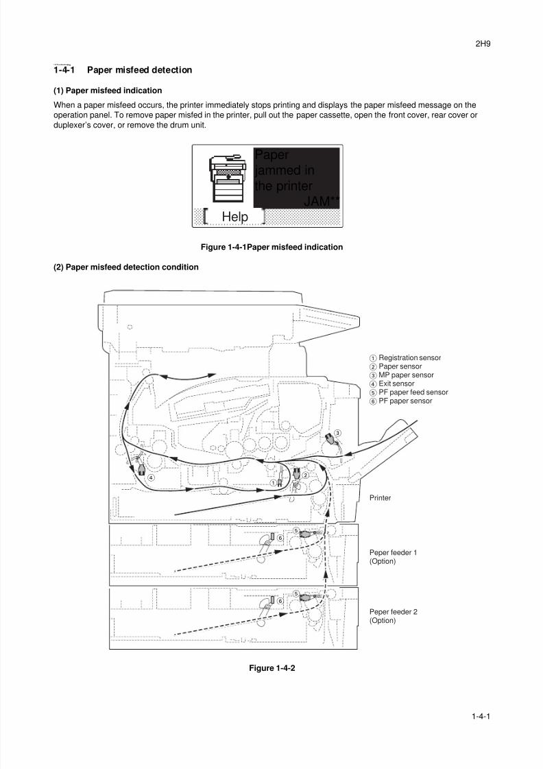
8/3/2019 Servi manualKM-2810ENSMR3
http://slidepdf.com/reader/full/servi-manualkm-2810ensmr3 91/202
2H9
1-4-1
1-4 Troubleshooting
1-4-1 Paper misfeed detection
(1) Paper misfeed indication
When a paper misfeed occurs, the printer immediately stops printing and displays the paper misfeed message on the
operation panel. To remove paper misfed in the printer, pull out the paper cassette, open the front cover, rear cover or
duplexer’s cover, or remove the drum unit.
Figure 1-4-1Paper misfeed indication
(2) Paper misfeed detection condition
Figure 1-4-2
Help
Paper jammed inthe printer
JAM**
Peper feeder 1(Option)
Peper feeder 2(Option)
Printer
Registration sensor Paper sensor MP paper sensor Exit sensor PF paper feed sensor
PF paper sensor
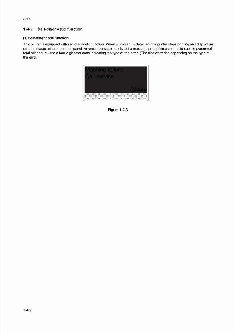
8/3/2019 Servi manualKM-2810ENSMR3
http://slidepdf.com/reader/full/servi-manualkm-2810ensmr3 92/202
2H9
1-4-2
1-4-2 Self-diagnostic function
(1) Self-diagnostic function
This printer is equipped with self-diagnostic function. When a problem is detected, the printer stops printing and display an
error message on the operation panel. An error message consists of a message prompting a contact to service personnel,
total print count, and a four-digit error code indicating the type of the error. (The display varies depending on the type of
the error.)
Figure 1-4-3
Machine failure.Call service.
C####
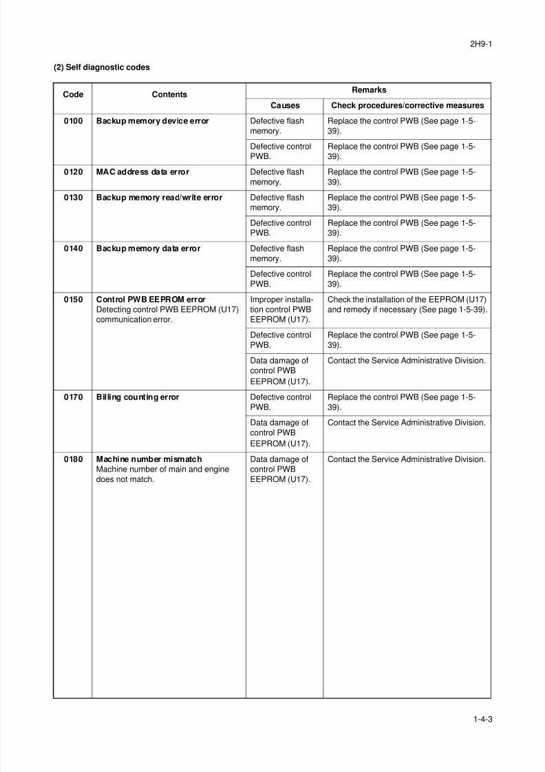
8/3/2019 Servi manualKM-2810ENSMR3
http://slidepdf.com/reader/full/servi-manualkm-2810ensmr3 93/202
2H9-1
1-4-3
(2) Self diagnostic codes
Code ContentsRemarks
Causes Check procedures/corrective measures
0100 Backup memory device error Defective flash
memory.
Replace the control PWB (See page 1-5-
39).Defective control
PWB.
Replace the control PWB (See page 1-5-
39).
0120 MAC address data error Defective flash
memory.
Replace the control PWB (See page 1-5-
39).
0130 Backup memory read/write error Defective flash
memory.
Replace the control PWB (See page 1-5-
39).
Defective control
PWB.
Replace the control PWB (See page 1-5-
39).
0140 Backup memory data error Defective flash
memory.
Replace the control PWB (See page 1-5-
39).
Defective control
PWB.
Replace the control PWB (See page 1-5-
39).
0150 Control PWB EEPROM error
Detecting control PWB EEPROM (U17)
communication error.
Improper installa-
tion control PWB
EEPROM (U17).
Check the installation of the EEPROM (U17)
and remedy if necessary (See page 1-5-39).
Defective control
PWB.
Replace the control PWB (See page 1-5-
39).
Data damage of
control PWB
EEPROM (U17).
Contact the Service Administrative Division.
0170 Billing counting error Defective control
PWB.
Replace the control PWB (See page 1-5-
39).
Data damage of
control PWB
EEPROM (U17).
Contact the Service Administrative Division.
0180 Machine number mismatch
Machine number of main and engine
does not match.
Data damage of
control PWB
EEPROM (U17).
Contact the Service Administrative Division.
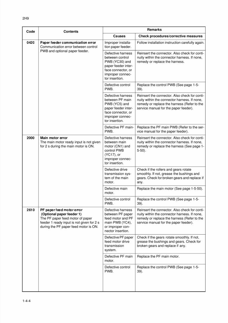
8/3/2019 Servi manualKM-2810ENSMR3
http://slidepdf.com/reader/full/servi-manualkm-2810ensmr3 94/202
2H9
1-4-4
0420 Paper feeder communication error
Communication error between control
PWB and optional paper feeder.
Improper installa-
tion paper feeder.
Follow installation instruction carefully again.
Defective harness
between controlPWB (YC30) and
paper feeder inter-
face connector, or
improper connec-
tor insertion.
Reinsert the connector. Also check for conti-
nuity within the connector harness. If none,remedy or replace the harness.
Defective control
PWB.
Replace the control PWB (See page 1-5-
39).
Defective harness
between PF main
PWB (YC5) and
paper feeder inter-
face connector, orimproper connec-
tor insertion.
Reinsert the connector. Also check for conti-
nuity within the connector harness. If none,
remedy or replace the harness (Refer to the
service manual for the paper feeder).
Defective PF main-
PWB.
Replace the PF main PWB (Refer to the ser-
vice manual for the paper feeder).
2000 Main motor error
The main motor ready input is not given
for 2 s during the main motor is ON.
Defective harness
between main
motor (CN1) and
control PWB
(YC17), or
improper connec-
tor insertion.
Reinsert the connector. Also check for conti-
nuity within the connector harness. If none,
remedy or replace the harness (See page 1-
5-50).
Defective drivetransmission sys-
tem of the main
motor.
Check if the rollers and gears rotatesmoothly. If not, grease the bushings and
gears. Check for broken gears and replace if
any.
Defective main
motor.
Replace the main motor (See page 1-5-50).
Defective control
PWB.
Replace the control PWB (See page 1-5-
39).
2610 PF paper feed motor error
(Optional paper feeder 1)
The PF paper feed motor of paper
feeder 1 ready input is not given for 2 s
during the PF paper feed motor is ON.
Defective harness
between PF paper
feed motor and PF
main PWB (YC4),
or improper con-nector insertion.
Reinsert the connector. Also check for conti-
nuity within the connector harness. If none,
remedy or replace the harness (Refer to the
service manual for the paper feeder).
Defective PF paper
feed motor drive
transmission
system.
Check if the gears rotate smoothly. If not,
grease the bushings and gears. Check for
broken gears and replace if any.
Defective PF main
motor.
Replace the PF main motor.
Defective control
PWB.
Replace the control PWB (See page 1-5-
39).
Code ContentsRemarks
Causes Check procedures/corrective measures
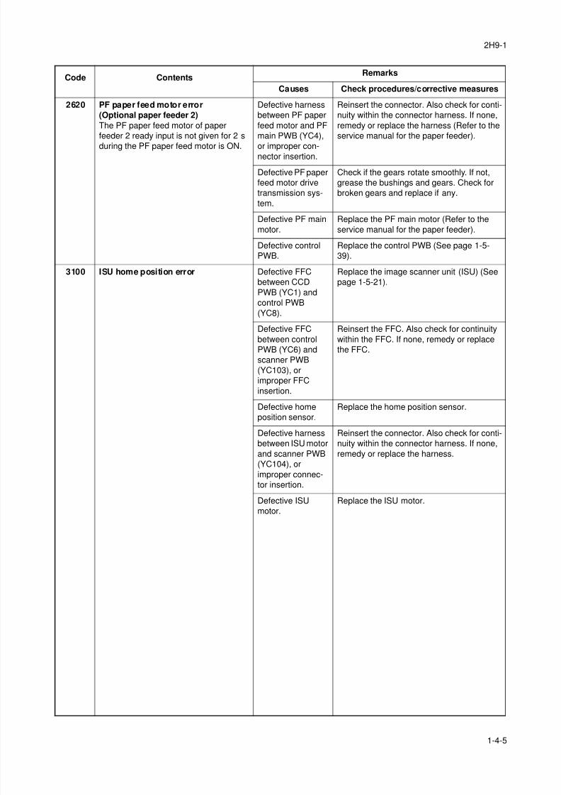
8/3/2019 Servi manualKM-2810ENSMR3
http://slidepdf.com/reader/full/servi-manualkm-2810ensmr3 95/202
2H9-1
1-4-5
2620 PF paper feed motor error
(Optional paper feeder 2)
The PF paper feed motor of paper
feeder 2 ready input is not given for 2 sduring the PF paper feed motor is ON.
Defective harness
between PF paper
feed motor and PF
main PWB (YC4),or improper con-
nector insertion.
Reinsert the connector. Also check for conti-
nuity within the connector harness. If none,
remedy or replace the harness (Refer to the
service manual for the paper feeder).
Defective PF paper
feed motor drive
transmission sys-
tem.
Check if the gears rotate smoothly. If not,
grease the bushings and gears. Check for
broken gears and replace if any.
Defective PF main
motor.
Replace the PF main motor (Refer to the
service manual for the paper feeder).
Defective control
PWB.
Replace the control PWB (See page 1-5-
39).
3100 ISU home position error Defective FFC
between CCD
PWB (YC1) and
control PWB
(YC8).
Replace the image scanner unit (ISU) (See
page 1-5-21).
Defective FFC
between control
PWB (YC6) and
scanner PWB
(YC103), or
improper FFC
insertion.
Reinsert the FFC. Also check for continuity
within the FFC. If none, remedy or replace
the FFC.
Defective home
position sensor.
Replace the home position sensor.
Defective harness
between ISU motor
and scanner PWB
(YC104), or
improper connec-
tor insertion.
Reinsert the connector. Also check for conti-
nuity within the connector harness. If none,
remedy or replace the harness.
Defective ISU
motor.
Replace the ISU motor.
Code ContentsRemarks
Causes Check procedures/corrective measures
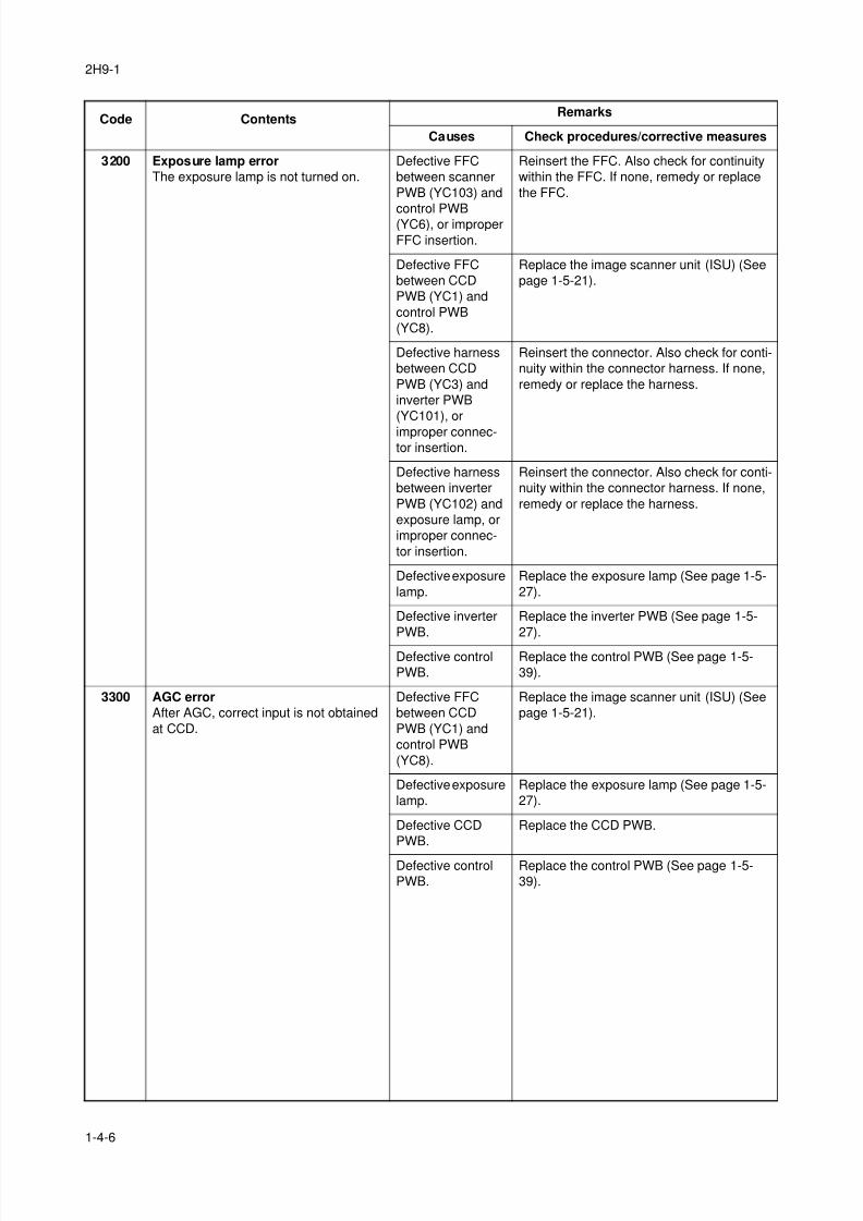
8/3/2019 Servi manualKM-2810ENSMR3
http://slidepdf.com/reader/full/servi-manualkm-2810ensmr3 96/202
2H9-1
1-4-6
3200 Exposure lamp error
The exposure lamp is not turned on.
Defective FFC
between scanner
PWB (YC103) and
control PWB(YC6), or improper
FFC insertion.
Reinsert the FFC. Also check for continuity
within the FFC. If none, remedy or replace
the FFC.
Defective FFC
between CCD
PWB (YC1) and
control PWB
(YC8).
Replace the image scanner unit (ISU) (See
page 1-5-21).
Defective harness
between CCD
PWB (YC3) and
inverter PWB
(YC101), or
improper connec-tor insertion.
Reinsert the connector. Also check for conti-
nuity within the connector harness. If none,
remedy or replace the harness.
Defective harness
between inverter
PWB (YC102) and
exposure lamp, or
improper connec-
tor insertion.
Reinsert the connector. Also check for conti-
nuity within the connector harness. If none,
remedy or replace the harness.
Defective exposure
lamp.
Replace the exposure lamp (See page 1-5-
27).
Defective inverter
PWB.
Replace the inverter PWB (See page 1-5-
27).
Defective control
PWB.
Replace the control PWB (See page 1-5-
39).
3300 AGC error
After AGC, correct input is not obtained
at CCD.
Defective FFC
between CCD
PWB (YC1) and
control PWB
(YC8).
Replace the image scanner unit (ISU) (See
page 1-5-21).
Defective exposure
lamp.
Replace the exposure lamp (See page 1-5-
27).
Defective CCD
PWB.
Replace the CCD PWB.
Defective control
PWB.
Replace the control PWB (See page 1-5-
39).
Code ContentsRemarks
Causes Check procedures/corrective measures
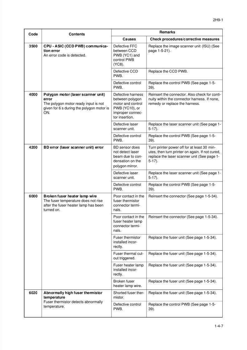
8/3/2019 Servi manualKM-2810ENSMR3
http://slidepdf.com/reader/full/servi-manualkm-2810ensmr3 97/202
2H9-1
1-4-7
3500 CPU - ASIC (CCD PWB) communica-
tion error
An error code is detected.
Defective FFC
between CCD
PWB (YC1) and
control PWB(YC8).
Replace the image scanner unit (ISU) (See
page 1-5-21).
Defective CCD
PWB.
Replace the CCD PWB.
Defective control
PWB.
Replace the control PWB (See page 1-5-
39).
4000 Polygon motor (laser scanner unit)
error
The polygon motor ready input is not
given for 6 s during the polygon motor is
ON.
Defective harness
between polygon
motor and control
PWB (YC10), or
improper connec-
tor insertion.
Reinsert the connector. Also check for conti-
nuity within the connector harness. If none,
remedy or replace the harness.
Defective laser
scanner unit.
Replace the laser scanner unit (See page 1-
5-17).
Defective control
PWB.
Replace the control PWB (See page 1-5-
39).
4200 BD error (laser scanner unit) error BD sensor does
not detect laser
beam due to con-
densation on the
polygon mirror.
Turn printer power off for at least 30 min-
utes, then turn printer on again. If not cured,
replace the laser scanner unit (See page 1-
5-17).
Defective laser
scanner unit.
Replace the laser scanner unit (See page 1-
5-17).
Defective controlPWB.
Replace the control PWB (See page 1-5-39).
6000 Broken fuser heater lamp wire
The fuser temperature does not rise
after the fuser heater lamp has been
turned on.
Poor contact in the
fuser thermistor
connector termi-
nals.
Reinsert the connector (See page 1-5-34).
Poor contact in the
fuser heater lamp
connector termi-
nals.
Reinsert the connector (See page 1-5-34).
Fuser thermistor
installed incor-
rectly.
Replace the fuser unit (See page 1-5-34).
Fuser thermal cut-
out triggered.
Replace the fuser unit (See page 1-5-34).
Fuser heater lamp
installed incor-
rectly.
Replace the fuser unit (See page 1-5-34).
Broken fuser
heater lamp wire.
Replace the fuser unit (See page 1-5-34).
6020 Abnormally high fuser thermistor
temperature
Fuser thermistor detects abnormally
temperature.
Shorted fuser ther-
mistor.
Replace the fuser unit (See page 1-5-34).
Defective control
PWB.
Replace the control PWB (See page 1-5-
39).
Code ContentsRemarks
Causes Check procedures/corrective measures
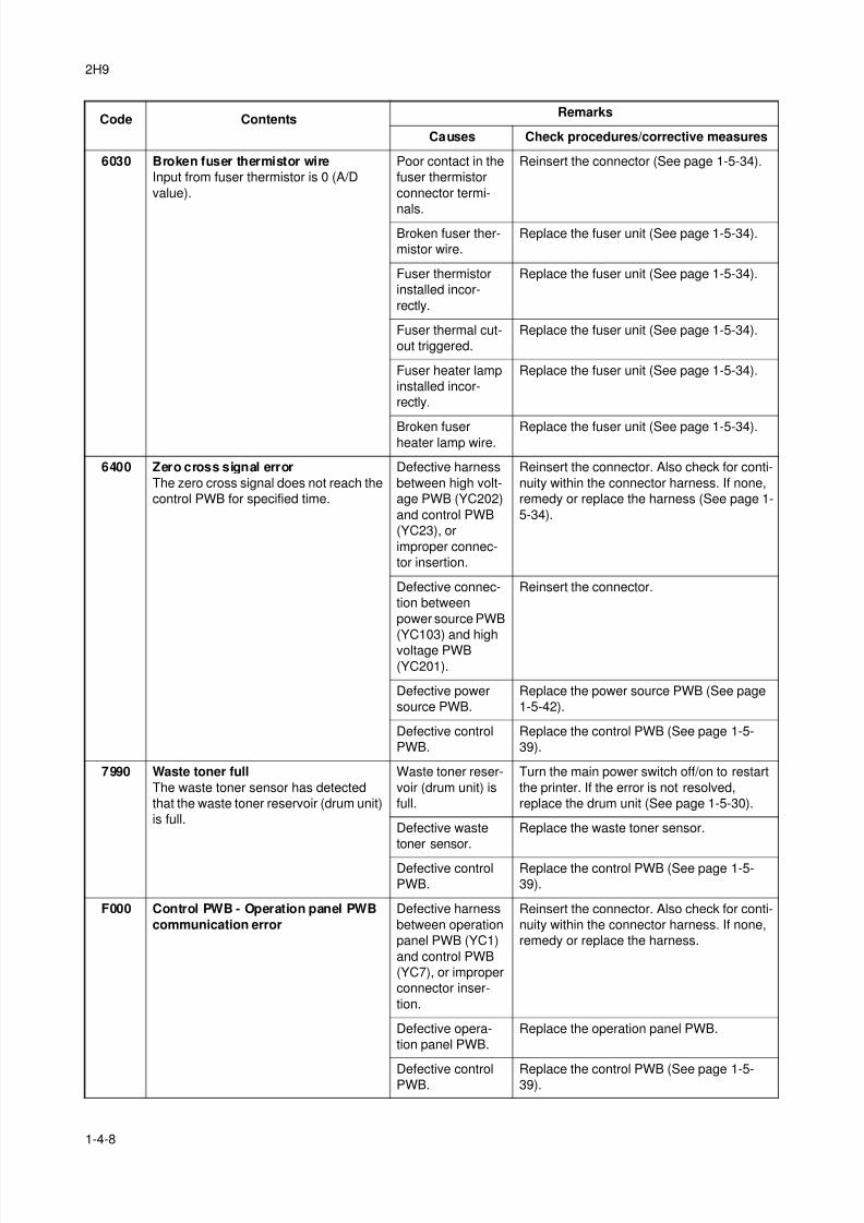
8/3/2019 Servi manualKM-2810ENSMR3
http://slidepdf.com/reader/full/servi-manualkm-2810ensmr3 98/202
2H9
1-4-8
6030 Broken fuser thermistor wire
Input from fuser thermistor is 0 (A/D
value).
Poor contact in the
fuser thermistor
connector termi-
nals.
Reinsert the connector (See page 1-5-34).
Broken fuser ther-
mistor wire.
Replace the fuser unit (See page 1-5-34).
Fuser thermistor
installed incor-
rectly.
Replace the fuser unit (See page 1-5-34).
Fuser thermal cut-
out triggered.
Replace the fuser unit (See page 1-5-34).
Fuser heater lamp
installed incor-
rectly.
Replace the fuser unit (See page 1-5-34).
Broken fuserheater lamp wire.
Replace the fuser unit (See page 1-5-34).
6400 Zero cross signal error
The zero cross signal does not reach the
control PWB for specified time.
Defective harness
between high volt-
age PWB (YC202)
and control PWB
(YC23), or
improper connec-
tor insertion.
Reinsert the connector. Also check for conti-
nuity within the connector harness. If none,
remedy or replace the harness (See page 1-
5-34).
Defective connec-
tion between
power source PWB
(YC103) and high
voltage PWB
(YC201).
Reinsert the connector.
Defective power
source PWB.
Replace the power source PWB (See page
1-5-42).
Defective control
PWB.
Replace the control PWB (See page 1-5-
39).
7990 Waste toner full
The waste toner sensor has detected
that the waste toner reservoir (drum unit)
is full.
Waste toner reser-
voir (drum unit) is
full.
Turn the main power switch off/on to restart
the printer. If the error is not resolved,
replace the drum unit (See page 1-5-30).
Defective waste
toner sensor.
Replace the waste toner sensor.
Defective control
PWB.
Replace the control PWB (See page 1-5-
39).
F000 Control PWB - Operation panel PWB
communication error
Defective harness
between operation
panel PWB (YC1)
and control PWB
(YC7), or improper
connector inser-
tion.
Reinsert the connector. Also check for conti-
nuity within the connector harness. If none,
remedy or replace the harness.
Defective opera-
tion panel PWB.
Replace the operation panel PWB.
Defective controlPWB.
Replace the control PWB (See page 1-5-39).
Code ContentsRemarks
Causes Check procedures/corrective measures
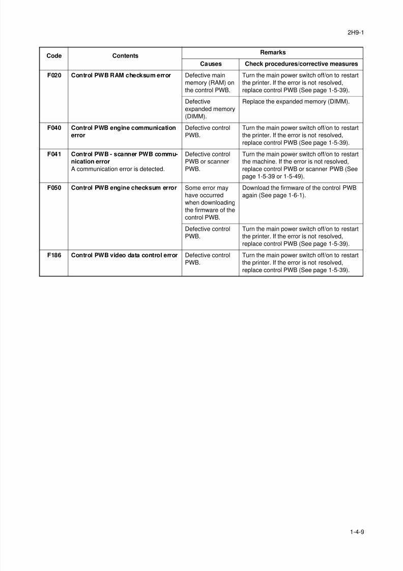
8/3/2019 Servi manualKM-2810ENSMR3
http://slidepdf.com/reader/full/servi-manualkm-2810ensmr3 99/202
2H9-1
1-4-9
F020 Control PWB RAM checksum error Defective main
memory (RAM) on
the control PWB.
Turn the main power switch off/on to restart
the printer. If the error is not resolved,
replace control PWB (See page 1-5-39).
Defectiveexpanded memory
(DIMM).
Replace the expanded memory (DIMM).
F040 Control PWB engine communication
error
Defective control
PWB.
Turn the main power switch off/on to restart
the printer. If the error is not resolved,
replace control PWB (See page 1-5-39).
F041 Control PWB - scanner PWB commu-
nication error
A communication error is detected.
Defective control
PWB or scanner
PWB.
Turn the main power switch off/on to restart
the machine. If the error is not resolved,
replace control PWB or scanner PWB (See
page 1-5-39 or 1-5-49).
F050 Control PWB engine checksum error Some error may
have occurred
when downloading
the firmware of the
control PWB.
Download the firmware of the control PWB
again (See page 1-6-1).
Defective control
PWB.
Turn the main power switch off/on to restart
the printer. If the error is not resolved,
replace control PWB (See page 1-5-39).
F186 Control PWB video data control error Defective control
PWB.
Turn the main power switch off/on to restart
the printer. If the error is not resolved,
replace control PWB (See page 1-5-39).
Code ContentsRemarks
Causes Check procedures/corrective measures
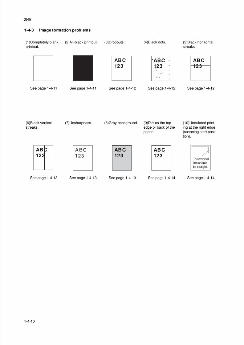
8/3/2019 Servi manualKM-2810ENSMR3
http://slidepdf.com/reader/full/servi-manualkm-2810ensmr3 100/202
2H9
1-4-10
1-4-3 Image formation problems
(1)Completely blank
printout.
(2)All-black printout. (3)Dropouts. (4)Black dots. (5)Black horizontal
streaks.
See page 1-4-11 See page 1-4-11 See page 1-4-12 See page 1-4-12 See page 1-4-12
(6)Black vertical
streaks.
(7)Unsharpness. (8)Gray background. (9)Dirt on the top
edge or back of the
paper.
(10)Undulated print-
ing at the right edge
(scanning start posi-
tion).
See page 1-4-13 See page 1-4-13 See page 1-4-13 See page 1-4-14 See page 1-4-14
ABC123
ABC123
ABC123
ABC
123
ABC
123
ABC
123This vertical
line should
be straight.
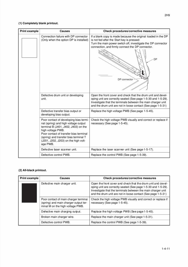
8/3/2019 Servi manualKM-2810ENSMR3
http://slidepdf.com/reader/full/servi-manualkm-2810ensmr3 101/202
2H9
1-4-11
(1) Completely blank printout.
(2) All-black printout.
Print example Causes Check procedures/corrective measures
Connection failure with DP connector
(Only when the option DP is installed)
If a blank copy is made because the original loaded in the DP
is not fed after the Start key is pressed:
Turn the main power switch off, investigate the DP connector
connection, and firmly connect the DP connector.
Defective drum unit or developing
unit.
Open the front cover and check that the drum unit and devel-
oping unit are correctly seated (See page 1-5-30 and 1-5-29).
Investigate that the terminals between the main charger unit
and the drum unit are not in loose contact (See page 1-5-31)
Defective transfer bias output or
developing bias output.
Replace the high voltage PWB (See page 1-5-45).
Poor contact of developing bias termi-
nal (spring) and high voltage output
terminal B (J401, J402, J403) on the
high voltage PWB.
Poor contact of transfer bias terminal
(spring) and transfer bias terminal T
(J201, J202, J203) on the high volt-age PWB.
Check the high voltage PWB visually and correct or replace if
necessary (See page 1-5-45).
Defective laser scanner unit. Replace the laser scanner unit (See page 1-5-17).
Defective control PWB. Replace the control PWB (See page 1-5-39).
Print example Causes Check procedures/corrective measures
Defective main charger unit. Open the front cover and check that the drum unit and devel-
oping unit are correctly seated (See page 1-5-30 and 1-5-29).Investigate that the terminals between the main charger unit
and the drum unit are not in loose contact (See page 1-5-31)
Poor contact of main charger terminal
(spring) and main charger output ter-
minal M on the high voltage PWB.
Check the high voltage PWB visually and correct or replace if
necessary (See page 1-5-45).
Defective main charging output. Replace the high voltage PWB (See page 1-5-45).
Broken main charger wire. Replace the main charger unit (See page 1-5-31).
Defective control PWB. Replace the control PWB (See page 1-5-39).
DP connector
DP
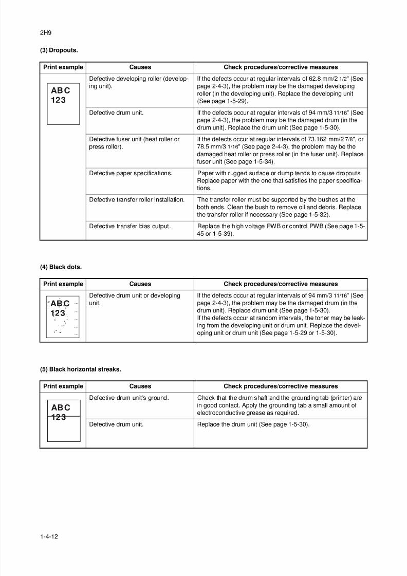
8/3/2019 Servi manualKM-2810ENSMR3
http://slidepdf.com/reader/full/servi-manualkm-2810ensmr3 102/202
2H9
1-4-12
(3) Dropouts.
(4) Black dots.
(5) Black horizontal streaks.
Print example Causes Check procedures/corrective measures
Defective developing roller (develop-
ing unit).
If the defects occur at regular intervals of 62.8 mm/2 1/2" (See
page 2-4-3), the problem may be the damaged developing
roller (in the developing unit). Replace the developing unit
(See page 1-5-29).
Defective drum unit. If the defects occur at regular intervals of 94 mm/3 11/16" (See
page 2-4-3), the problem may be the damaged drum (in the
drum unit). Replace the drum unit (See page 1-5-30).
Defective fuser unit (heat roller or
press roller).
If the defects occur at regular intervals of 73.162 mm/2 7/8", or
78.5 mm/3 1/16" (See page 2-4-3), the problem may be the
damaged heat roller or press roller (in the fuser unit). Replace
fuser unit (See page 1-5-34).
Defective paper specifications. Paper with rugged surface or dump tends to cause dropouts.
Replace paper with the one that satisfies the paper specifica-
tions.
Defective transfer roller installation. The transfer roller must be supported by the bushes at theboth ends. Clean the bush to remove oil and debris. Replace
the transfer roller if necessary (See page 1-5-32).
Defective transfer bias output. Replace the high voltage PWB or control PWB (See page 1-5-
45 or 1-5-39).
Print example Causes Check procedures/corrective measures
Defective drum unit or developing
unit.
If the defects occur at regular intervals of 94 mm/3 11/16" (See
page 2-4-3), the problem may be the damaged drum (in thedrum unit). Replace drum unit (See page 1-5-30).
If the defects occur at random intervals, the toner may be leak-
ing from the developing unit or drum unit. Replace the devel-
oping unit or drum unit (See page 1-5-29 or 1-5-30).
Print example Causes Check procedures/corrective measures
Defective drum unit's ground. Check that the drum shaft and the grounding tab (printer) are
in good contact. Apply the grounding tab a small amount ofelectroconductive grease as required.
Defective drum unit. Replace the drum unit (See page 1-5-30).
ABC
123
ABC123
ABC
123
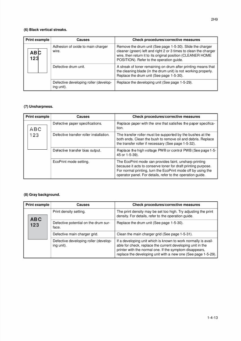
8/3/2019 Servi manualKM-2810ENSMR3
http://slidepdf.com/reader/full/servi-manualkm-2810ensmr3 103/202
2H9
1-4-13
(6) Black vertical streaks.
(7) Unsharpness.
(8) Gray background.
Print example Causes Check procedures/corrective measures
Adhesion of oxide to main charger
wire.
Remove the drum unit (See page 1-5-30). Slide the charger
cleaner (green) left and right 2 or 3 times to clean the charger
wire, then return it to its original position (CLEANER HOME
POSITION). Refer to the operation guide.
Defective drum unit. A streak of toner remaining on drum after printing means that
the cleaning blade (in the drum unit) is not working properly.
Replace the drum unit (See page 1-5-30).
Defective developing roller (develop-
ing unit).
Replace the developing unit (See page 1-5-29).
Print example Causes Check procedures/corrective measures
Defective paper specifications. Replace paper with the one that satisfies the paper specifica-
tion.
Defective transfer roller installation. The transfer roller must be supported by the bushes at the
both ends. Clean the bush to remove oil and debris. Replace
the transfer roller if necessary (See page 1-5-32).
Defective transfer bias output. Replace the high voltage PWB or control PWB (See page 1-5-
45 or 1-5-39).
EcoPrint mode setting. The EcoPrint mode can provides faint, unsharp printing
because it acts to conserve toner for draft printing purpose.
For normal printing, turn the EcoPrint mode off by using the
operator panel. For details, refer to the operation guide.
Print example Causes Check procedures/corrective measures
Print density setting. The print density may be set too high. Try adjusting the print
density. For details, refer to the operation guide.
Defective potential on the drum sur-
face.
Replace the drum unit (See page 1-5-30).
Defective main charger grid. Clean the main charger grid (See page 1-5-31).
Defective developing roller (develop-
ing unit).
If a developing unit which is known to work normally is avail-
able for check, replace the current developing unit in the
printer with the normal one. If the symptom disappears,
replace the developing unit with a new one (See page 1-5-29).
ABC
123
ABC
123
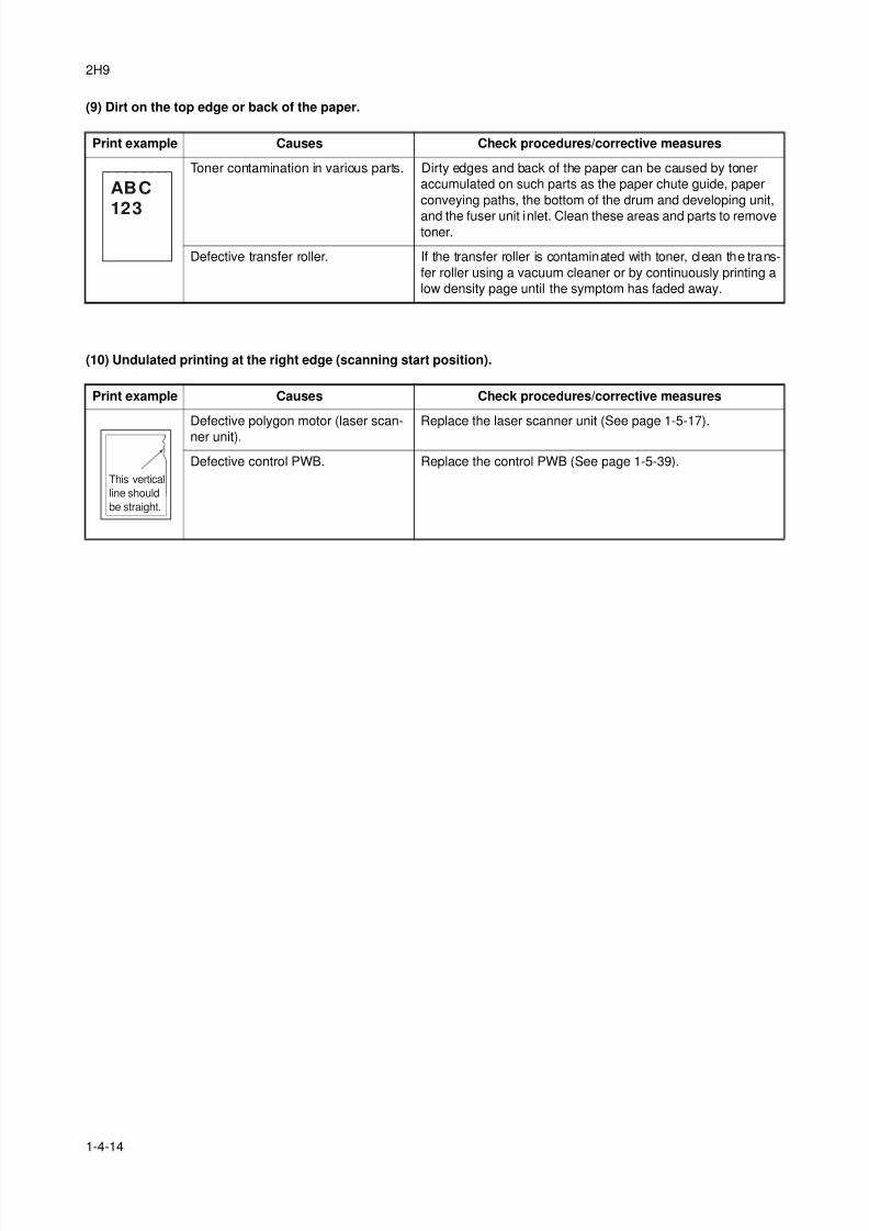
8/3/2019 Servi manualKM-2810ENSMR3
http://slidepdf.com/reader/full/servi-manualkm-2810ensmr3 104/202
2H9
1-4-14
(9) Dirt on the top edge or back of the paper.
(10) Undulated printing at the right edge (scanning start position).
Print example Causes Check procedures/corrective measures
Toner contamination in various parts. Dirty edges and back of the paper can be caused by toner
accumulated on such parts as the paper chute guide, paper
conveying paths, the bottom of the drum and developing unit,
and the fuser unit inlet. Clean these areas and parts to removetoner.
Defective transfer roller. If the transfer roller is contaminated with toner, clean the trans-
fer roller using a vacuum cleaner or by continuously printing a
low density page until the symptom has faded away.
Print example Causes Check procedures/corrective measures
Defective polygon motor (laser scan-
ner unit).
Replace the laser scanner unit (See page 1-5-17).
Defective control PWB. Replace the control PWB (See page 1-5-39).
ABC
123
This vertical
line should
be straight.
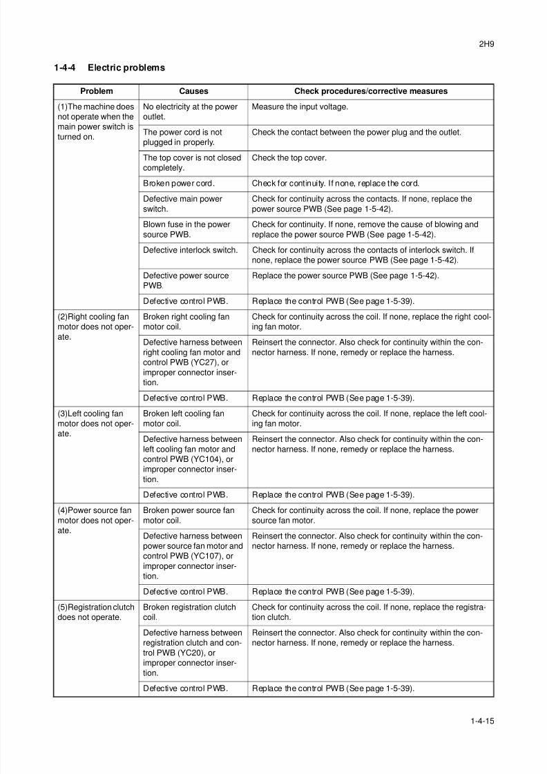
8/3/2019 Servi manualKM-2810ENSMR3
http://slidepdf.com/reader/full/servi-manualkm-2810ensmr3 105/202
2H9
1-4-15
1-4-4 Electric problems
Problem Causes Check procedures/corrective measures
(1)The machine does
not operate when the
main power switch is
turned on.
No electricity at the power
outlet.
Measure the input voltage.
The power cord is notplugged in properly. Check the contact between the power plug and the outlet.
The top cover is not closed
completely.
Check the top cover.
Broken power cord. Check for continuity. If none, replace the cord.
Defective main power
switch.
Check for continuity across the contacts. If none, replace the
power source PWB (See page 1-5-42).
Blown fuse in the power
source PWB.
Check for continuity. If none, remove the cause of blowing and
replace the power source PWB (See page 1-5-42).
Defective interlock switch. Check for continuity across the contacts of interlock switch. If
none, replace the power source PWB (See page 1-5-42).
Defective power source
PWB.
Replace the power source PWB (See page 1-5-42).
Defective control PWB. Replace the control PWB (See page 1-5-39).
(2)Right cooling fan
motor does not oper-
ate.
Broken right cooling fan
motor coil.
Check for continuity across the coil. If none, replace the right cool-
ing fan motor.
Defective harness between
right cooling fan motor and
control PWB (YC27), or
improper connector inser-
tion.
Reinsert the connector. Also check for continuity within the con-
nector harness. If none, remedy or replace the harness.
Defective control PWB. Replace the control PWB (See page 1-5-39).
(3)Left cooling fan
motor does not oper-
ate.
Broken left cooling fan
motor coil.
Check for continuity across the coil. If none, replace the left cool-
ing fan motor.
Defective harness between
left cooling fan motor and
control PWB (YC104), or
improper connector inser-
tion.
Reinsert the connector. Also check for continuity within the con-
nector harness. If none, remedy or replace the harness.
Defective control PWB. Replace the control PWB (See page 1-5-39).
(4)Power source fan
motor does not oper-
ate.
Broken power source fan
motor coil.
Check for continuity across the coil. If none, replace the power
source fan motor.
Defective harness between
power source fan motor and
control PWB (YC107), or
improper connector inser-
tion.
Reinsert the connector. Also check for continuity within the con-
nector harness. If none, remedy or replace the harness.
Defective control PWB. Replace the control PWB (See page 1-5-39).
(5)Registration clutch
does not operate.
Broken registration clutch
coil.
Check for continuity across the coil. If none, replace the registra-
tion clutch.
Defective harness between
registration clutch and con-
trol PWB (YC20), or
improper connector inser-
tion.
Reinsert the connector. Also check for continuity within the con-
nector harness. If none, remedy or replace the harness.
Defective control PWB. Replace the control PWB (See page 1-5-39).
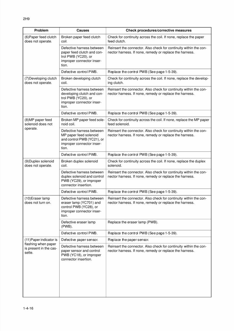
8/3/2019 Servi manualKM-2810ENSMR3
http://slidepdf.com/reader/full/servi-manualkm-2810ensmr3 106/202
2H9
1-4-16
(6)Paper feed clutch
does not operate.
Broken paper feed clutch
coil.
Check for continuity across the coil. If none, replace the paper
feed clutch.
Defective harness between
paper feed clutch and con-
trol PWB (YC20), orimproper connector inser-
tion.
Reinsert the connector. Also check for continuity within the con-
nector harness. If none, remedy or replace the harness.
Defective control PWB. Replace the control PWB (See page 1-5-39).
(7)Developing clutch
does not operate.
Broken developing clutch
coil.
Check for continuity across the coil. If none, replace the develop-
ing clutch.
Defective harness between
developing clutch and con-
trol PWB (YC20), or
improper connector inser-
tion.
Reinsert the connector. Also check for continuity within the con-
nector harness. If none, remedy or replace the harness.
Defective control PWB. Replace the control PWB (See page 1-5-39).
(8)MP paper feed
solenoid does not
operate.
Broken MP paper feed sole-
noid coil.
Check for continuity across the coil. If none, replace the MP paper
feed solenoid.
Defective harness between
MP paper feed solenoid
and control PWB (YC21), or
improper connector inser-
tion.
Reinsert the connector. Also check for continuity within the con-
nector harness. If none, remedy or replace the harness.
Defective control PWB. Replace the control PWB (See page 1-5-39).
(9)Duplex solenoid
does not operate.
Broken duplex solenoid
coil.
Check for continuity across the coil. If none, replace the duplex
solenoid.
Defective harness betweenduplex solenoid and control
PWB (YC29), or improper
connector insertion.
Reinsert the connector. Also check for continuity within the con-nector harness. If none, remedy or replace the harness.
Defective control PWB. Replace the control PWB (See page 1-5-39).
(10)Eraser lamp
does not turn on.
Defective harness between
eraser lamp (YC701) and
control PWB (YC28), or
improper connector inser-
tion.
Reinsert the connector. Also check for continuity within the con-
nector harness. If none, remedy or replace the harness.
Defective eraser lamp
(PWB).
Replace the eraser lamp (PWB).
Defective control PWB. Replace the control PWB (See page 1-5-39).
(11)Paper indicator is
flashing when paper
is present in the cas-
sette.
Defective paper sensor. Replace the paper sensor.
Defective harness between
paper sensor and control
PWB (YC18), or improper
connector insertion.
Reinsert the connector. Also check for continuity within the con-
nector harness. If none, remedy or replace the harness.
Problem Causes Check procedures/corrective measures

8/3/2019 Servi manualKM-2810ENSMR3
http://slidepdf.com/reader/full/servi-manualkm-2810ensmr3 107/202
2H9
1-4-17
(12)A paper jam in
the paper feed/con-
veying section or
fuser section is indi-
cated when the main
power switch isturned on.
A piece of paper torn from
paper is caught around reg-
istration sensor or exit sen-
sor.
Check and remove if any.
Defective registration sen-sor on the high voltage
PWB.
Replace the high voltage PWB (See page 1-5-45).
Defective exit sensor. Replace the exit sensor.
(13)Attention indica-
tor is lit when the
front cover is closed.
Defective interlock switch
on the power source PWB.
Check for continuity across the interlock switch. If there is no con-
tinuity when the interlock switch is on, replace the power source
PWB (See page 1-5-42).
Problem Causes Check procedures/corrective measures
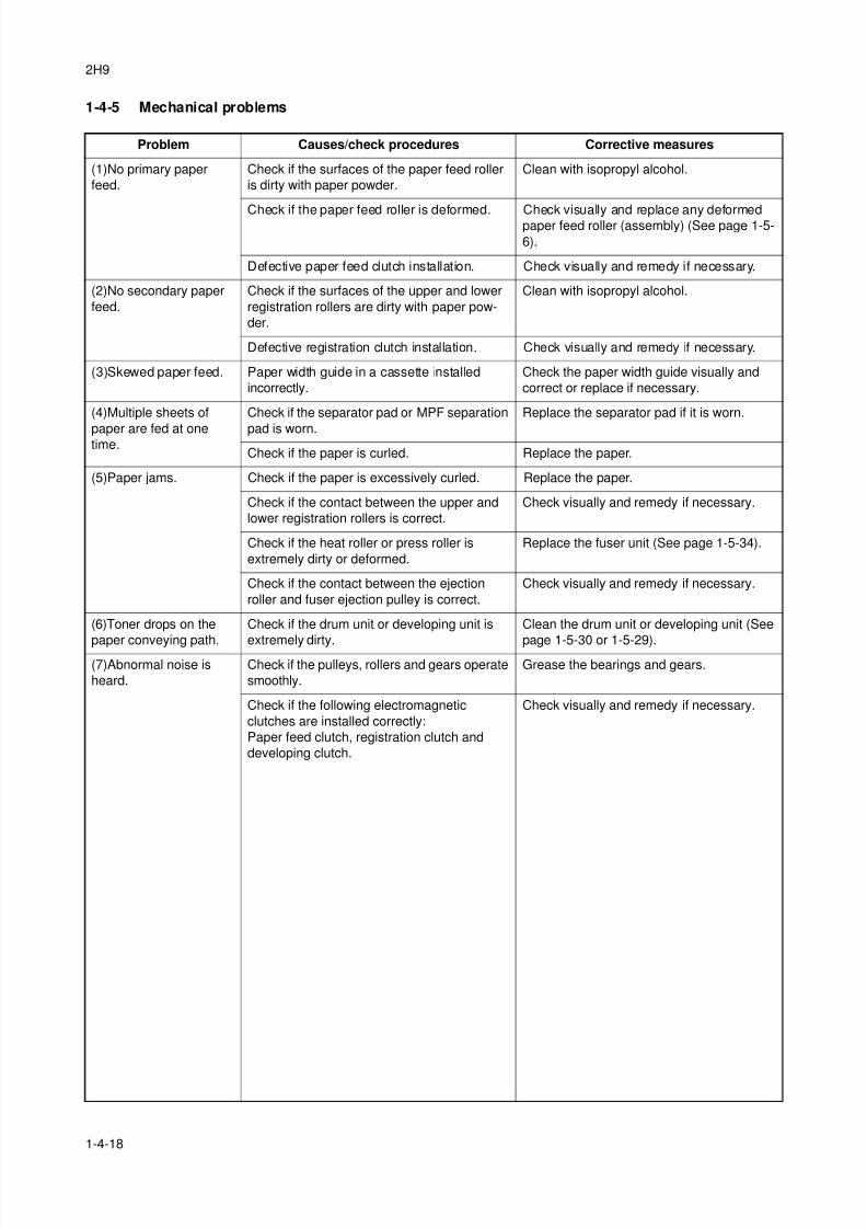
8/3/2019 Servi manualKM-2810ENSMR3
http://slidepdf.com/reader/full/servi-manualkm-2810ensmr3 108/202
2H9
1-4-18
1-4-5 Mechanical problems
Problem Causes/check procedures Corrective measures
(1)No primary paper
feed.
Check if the surfaces of the paper feed roller
is dirty with paper powder.
Clean with isopropyl alcohol.
Check if the paper feed roller is deformed. Check visually and replace any deformedpaper feed roller (assembly) (See page 1-5-
6).
Defective paper feed clutch installation. Check visually and remedy if necessary.
(2)No secondary paper
feed.
Check if the surfaces of the upper and lower
registration rollers are dirty with paper pow-
der.
Clean with isopropyl alcohol.
Defective registration clutch installation. Check visually and remedy if necessary.
(3)Skewed paper feed. Paper width guide in a cassette installed
incorrectly.
Check the paper width guide visually and
correct or replace if necessary.
(4)Multiple sheets of
paper are fed at onetime.
Check if the separator pad or MPF separation
pad is worn.
Replace the separator pad if it is worn.
Check if the paper is curled. Replace the paper.
(5)Paper jams. Check if the paper is excessively curled. Replace the paper.
Check if the contact between the upper and
lower registration rollers is correct.
Check visually and remedy if necessary.
Check if the heat roller or press roller is
extremely dirty or deformed.
Replace the fuser unit (See page 1-5-34).
Check if the contact between the ejection
roller and fuser ejection pulley is correct.
Check visually and remedy if necessary.
(6)Toner drops on the
paper conveying path.
Check if the drum unit or developing unit is
extremely dirty.
Clean the drum unit or developing unit (See
page 1-5-30 or 1-5-29).(7)Abnormal noise is
heard.
Check if the pulleys, rollers and gears operate
smoothly.
Grease the bearings and gears.
Check if the following electromagnetic
clutches are installed correctly:
Paper feed clutch, registration clutch and
developing clutch.
Check visually and remedy if necessary.
8/3/2019 Servi manualKM-2810ENSMR3
http://slidepdf.com/reader/full/servi-manualkm-2810ensmr3 109/202
2H9
1-5-1
1-5 AssemblyandDisassembly
1-5-1 Precautions for assembly and disassembly
(1) Precautions
Before starting disassembly, press the Power key on the operation panel to off. Make sure that the Power lamp is off
before turning off the main power switch. And then unplug the power cable from the wall outlet.
When the fax kit is installed, be sure to disconnect the modular code before starting disassembly.
When handling PWBs (printed wiring boards), do not touch parts with bare hands.The PWBs are susceptible to static charge.
Do not touch any PWB containing ICs with bare hands or any object prone to static charge.
When removing the hook of the connector, be sure to release the hook.
Take care not to get the cables caught.
To reassemble the parts, use the original screws. If the types and the sizes of screws are not known, refer to the PARTS
LIST.
(2) Drum
Note the following when handling or storing the drum.
When removing the drum unit, never expose the drum surface to strong direct light.
Keep the drum at an ambient temperature between -20°C/-4°F and 40°C/104°F and at a relative humidity not higher than90% RH. Avoid abrupt changes in temperature and humidity.
Avoid exposure to any substance which is harmful to or may affect the quality of the drum.
Do not touch the drum surface with any object. Should it be touched by hands or stained with oil, clean it.
(3) Toner
Store the toner container in a cool, dark place.
Avoid direct light and high humidity.
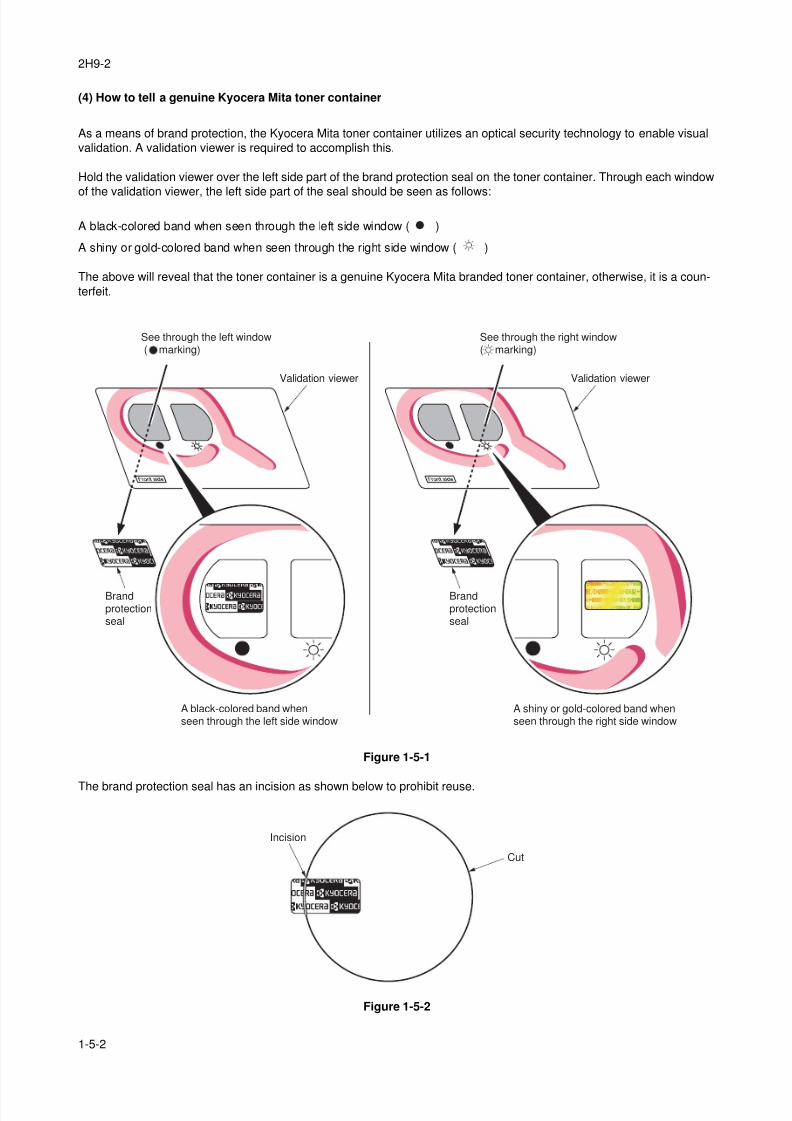
8/3/2019 Servi manualKM-2810ENSMR3
http://slidepdf.com/reader/full/servi-manualkm-2810ensmr3 110/202
2H9-2
1-5-2
(4) How to tell a genuine Kyocera Mita toner container
As a means of brand protection, the Kyocera Mita toner container utilizes an optical security technology to enable visual
validation. A validation viewer is required to accomplish this.
Hold the validation viewer over the left side part of the brand protection seal on the toner container. Through each window
of the validation viewer, the left side part of the seal should be seen as follows:
A black-colored band when seen through the left side window ( )
A shiny or gold-colored band when seen through the right side window ( )
The above will reveal that the toner container is a genuine Kyocera Mita branded toner container, otherwise, it is a coun-
terfeit.
Figure 1-5-1
The brand protection seal has an incision as shown below to prohibit reuse.
Figure 1-5-2
Validation viewerValidation viewer
Brandprotectionseal
Brandprotectionseal
See through the left window( marking)
See through the right window( marking)
A shiny or gold-colored band whenseen through the right side window
A black-colored band whenseen through the left side window
Incision
Cut
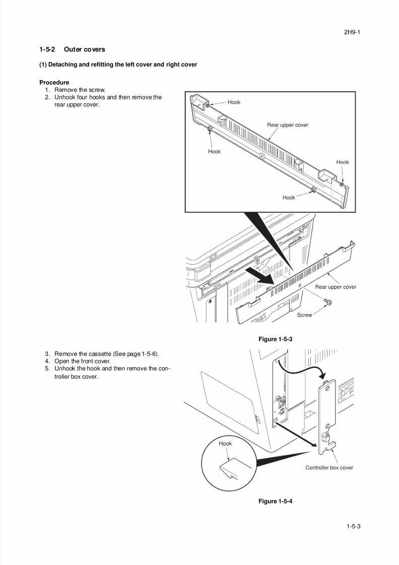
8/3/2019 Servi manualKM-2810ENSMR3
http://slidepdf.com/reader/full/servi-manualkm-2810ensmr3 111/202
2H9-1
1-5-3
1-5-2 Outer covers
(1) Detaching and refitting the left cover and right cover
Procedure
1. Remove the screw.
2. Unhook four hooks and then remove therear upper cover.
Figure 1-5-3
3. Remove the cassette (See page 1-5-6).
4. Open the front cover.
5. Unhook the hook and then remove the con-
troller box cover.
Figure 1-5-4
Screw
Hook
Hook
Hook
Hook
Rear upper cover
Rear upper cover
Controller box cover
Hook
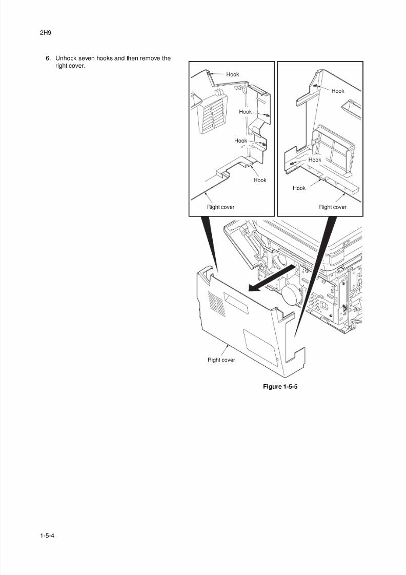
8/3/2019 Servi manualKM-2810ENSMR3
http://slidepdf.com/reader/full/servi-manualkm-2810ensmr3 112/202
2H9
1-5-4
6. Unhook seven hooks and then remove the
right cover.
Figure 1-5-5
Right cover
Right cover
Right cover
Hook
Hook
Hook
Hook
Hook
Hook
Hook
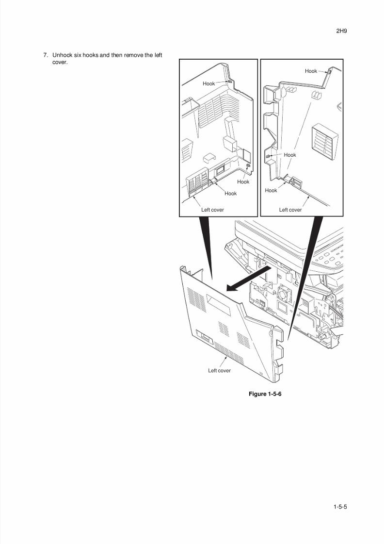
8/3/2019 Servi manualKM-2810ENSMR3
http://slidepdf.com/reader/full/servi-manualkm-2810ensmr3 113/202
2H9
1-5-5
7. Unhook six hooks and then remove the left
cover.
Figure 1-5-6
Left cover
Left cover
Left cover
Hook Hook
Hook
Hook
Hook
Hook
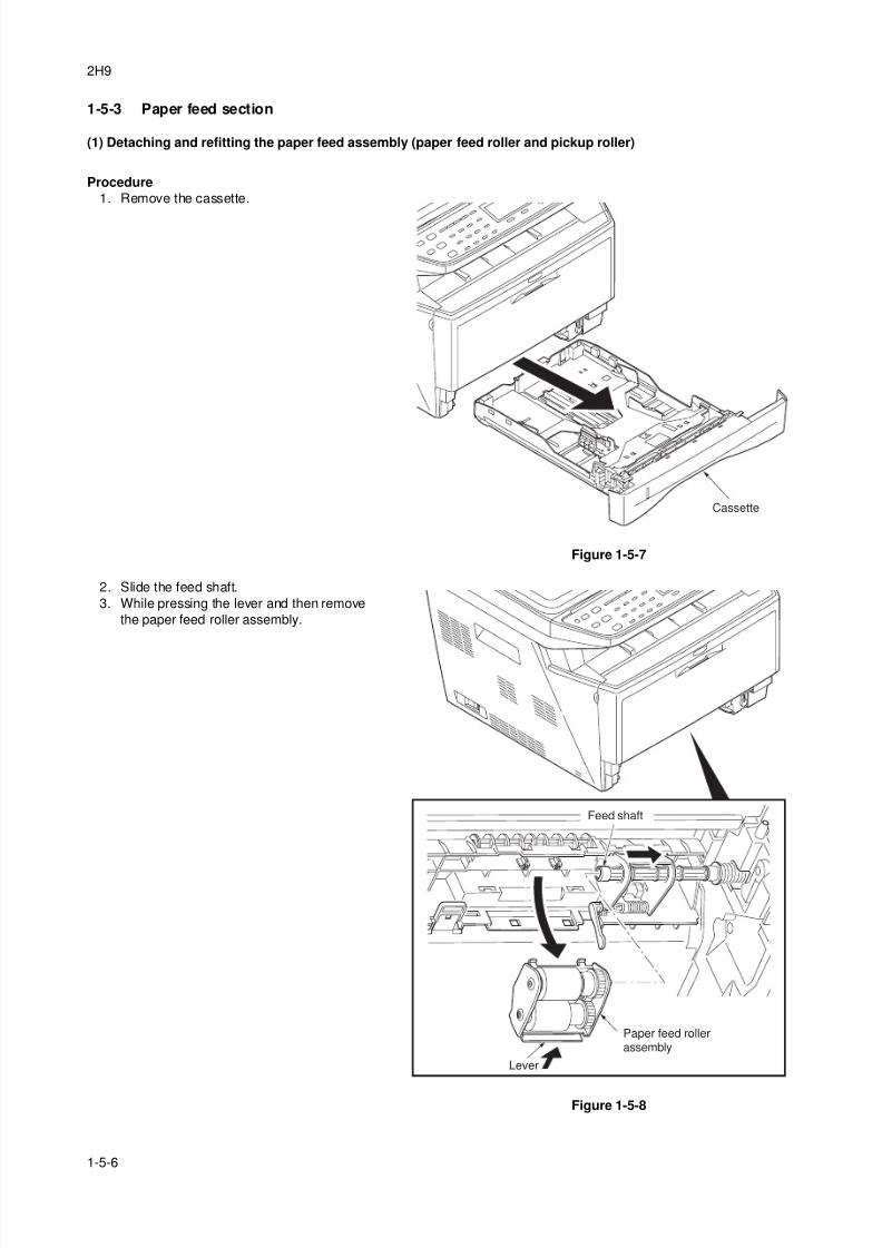
8/3/2019 Servi manualKM-2810ENSMR3
http://slidepdf.com/reader/full/servi-manualkm-2810ensmr3 114/202
2H9
1-5-6
1-5-3 Paper feed section
(1) Detaching and refitting the paper feed assembly (paper feed roller and pickup roller)
Procedure
1. Remove the cassette.
Figure 1-5-7
2. Slide the feed shaft.
3. While pressing the lever and then remove
the paper feed roller assembly.
Figure 1-5-8
Cassette
Lever
Feed shaft
Paper feed rollerassembly
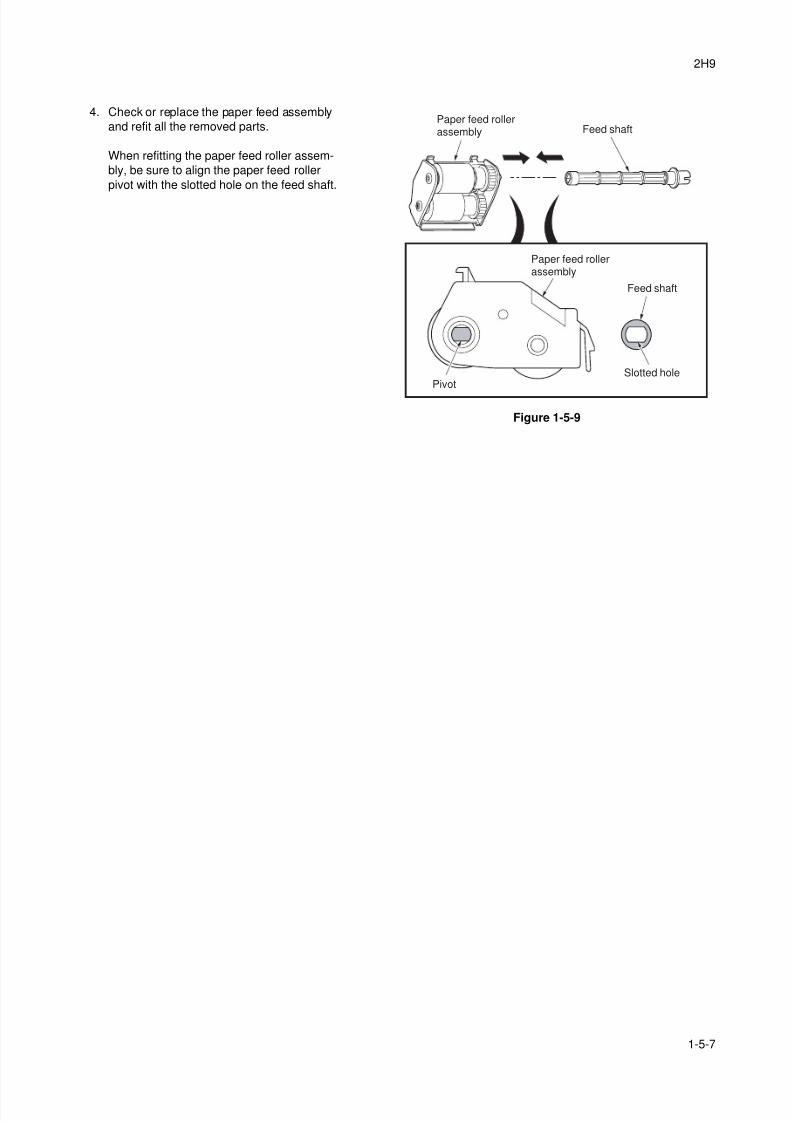
8/3/2019 Servi manualKM-2810ENSMR3
http://slidepdf.com/reader/full/servi-manualkm-2810ensmr3 115/202
2H9
1-5-7
4. Check or replace the paper feed assembly
and refit all the removed parts.
When refitting the paper feed roller assem-
bly, be sure to align the paper feed roller
pivot with the slotted hole on the feed shaft.
Figure 1-5-9
Paper feed rollerassembly
Paper feed rollerassembly
Feed shaft
Feed shaft
PivotSlotted hole
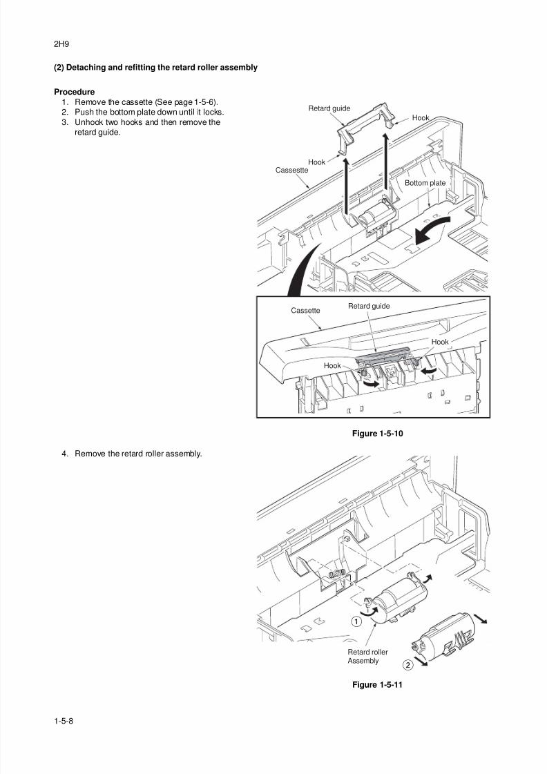
8/3/2019 Servi manualKM-2810ENSMR3
http://slidepdf.com/reader/full/servi-manualkm-2810ensmr3 116/202
2H9
1-5-8
(2) Detaching and refitting the retard roller assembly
Procedure
1. Remove the cassette (See page 1-5-6).
2. Push the bottom plate down until it locks.
3. Unhook two hooks and then remove the
retard guide.
Figure 1-5-10
4. Remove the retard roller assembly.
Figure 1-5-11
Retard guide
Retard guide
Cassestte
Cassette
Hook
Hook
Hook
Hook
Bottom plate
Retard rollerAssembly
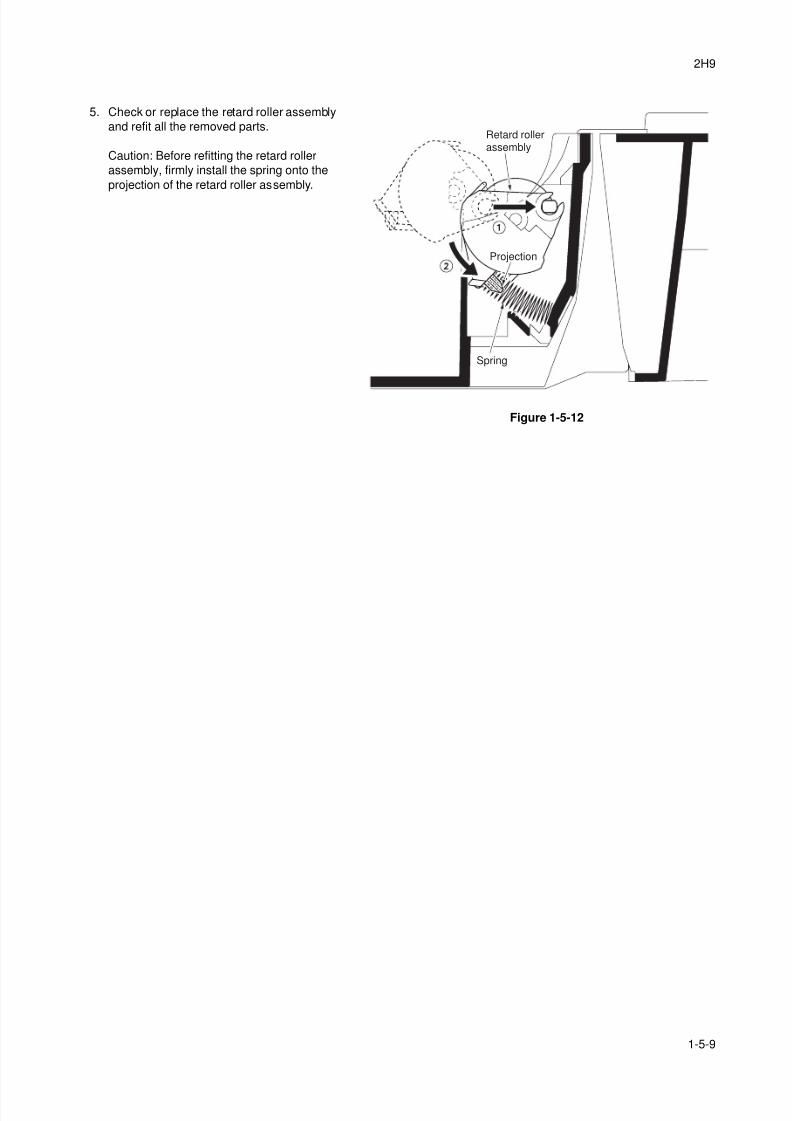
8/3/2019 Servi manualKM-2810ENSMR3
http://slidepdf.com/reader/full/servi-manualkm-2810ensmr3 117/202
2H9
1-5-9
5. Check or replace the retard roller assembly
and refit all the removed parts.
Caution: Before refitting the retard roller
assembly, firmly install the spring onto the
projection of the retard roller assembly.
Figure 1-5-12
Spring
Retard rollerassembly
Projection
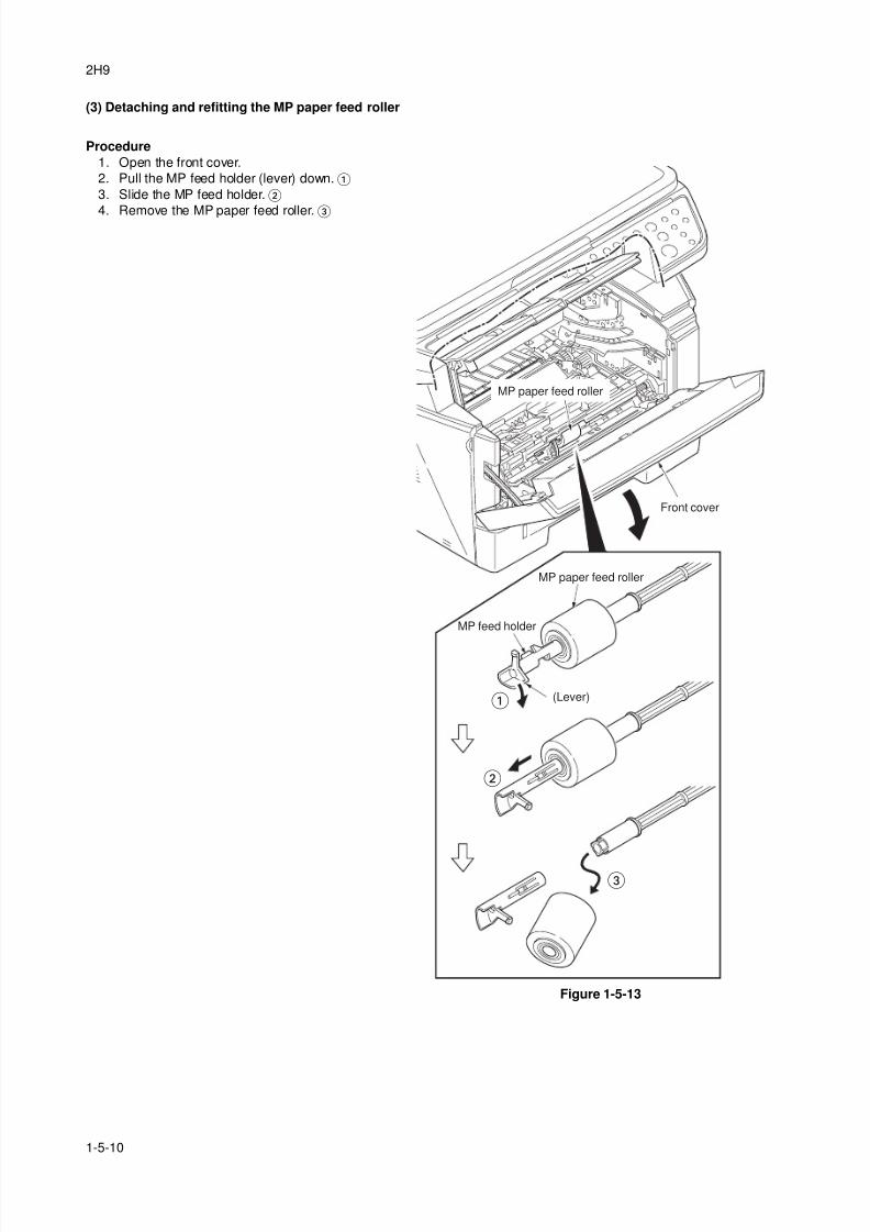
8/3/2019 Servi manualKM-2810ENSMR3
http://slidepdf.com/reader/full/servi-manualkm-2810ensmr3 118/202
2H9
1-5-10
(3) Detaching and refitting the MP paper feed roller
Procedure
1. Open the front cover.
2. Pull the MP feed holder (lever) down.
3. Slide the MP feed holder.
4. Remove the MP paper feed roller.
Figure 1-5-13
MP feed holder
(Lever)
Front cover
MP paper feed roller
MP paper feed roller
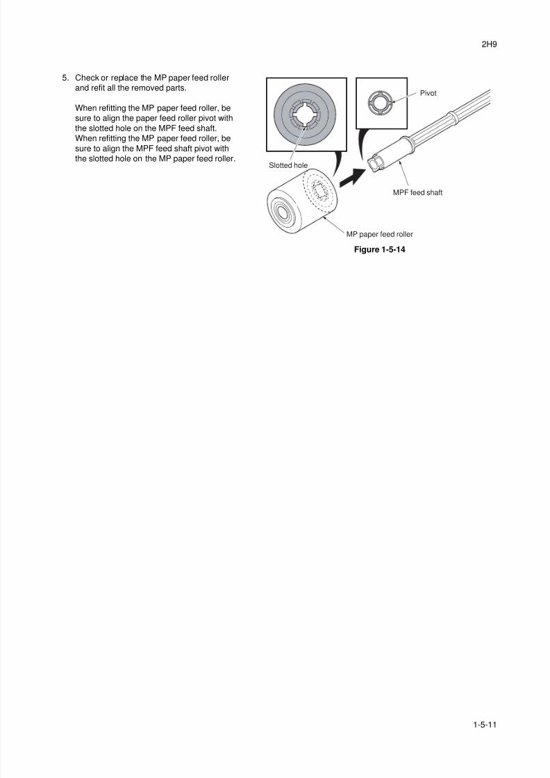
8/3/2019 Servi manualKM-2810ENSMR3
http://slidepdf.com/reader/full/servi-manualkm-2810ensmr3 119/202
2H9
1-5-11
5. Check or replace the MP paper feed roller
and refit all the removed parts.
When refitting the MP paper feed roller, be
sure to align the paper feed roller pivot with
the slotted hole on the MPF feed shaft.
When refitting the MP paper feed roller, besure to align the MPF feed shaft pivot with
the slotted hole on the MP paper feed roller.
Figure 1-5-14
MPF feed shaft
Pivot
MP paper feed roller
Slotted hole
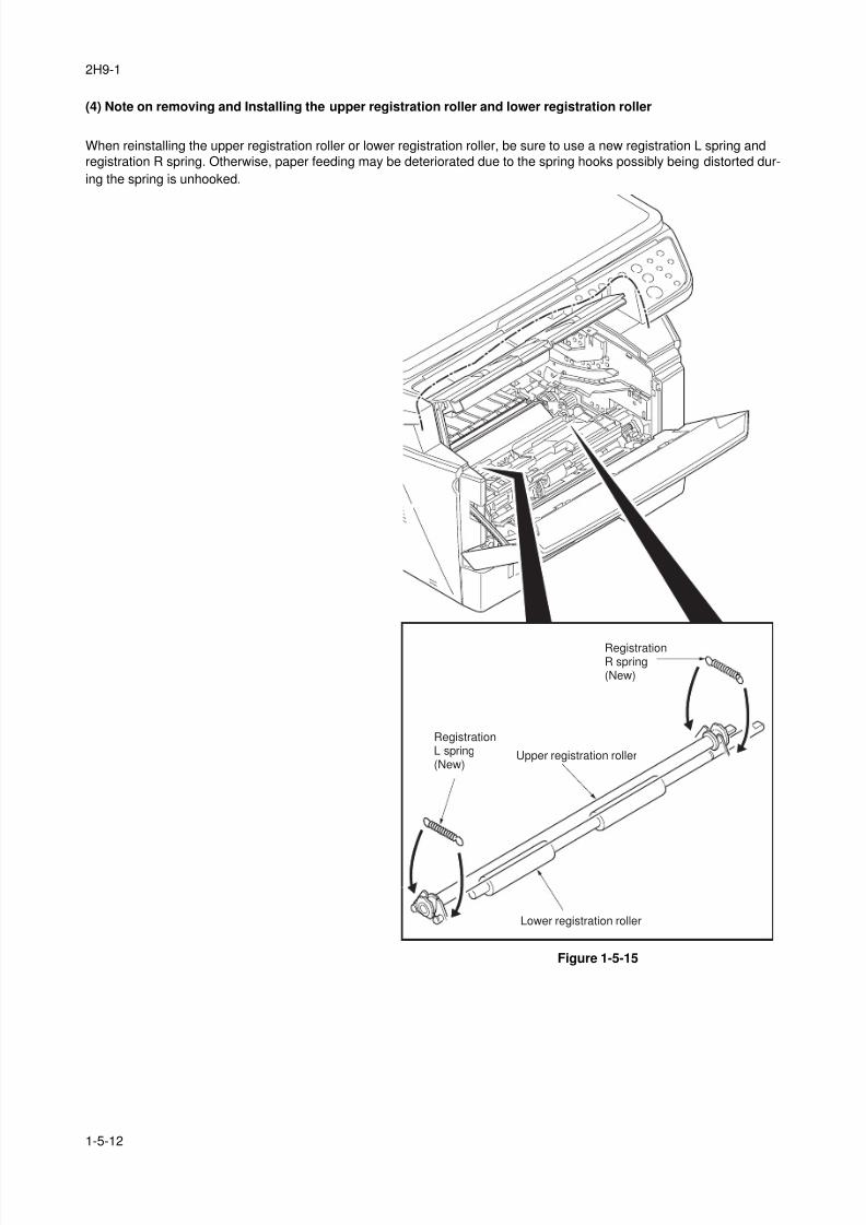
8/3/2019 Servi manualKM-2810ENSMR3
http://slidepdf.com/reader/full/servi-manualkm-2810ensmr3 120/202
2H9-1
1-5-12
(4) Note on removing and Installing the upper registration roller and lower registration roller
When reinstalling the upper registration roller or lower registration roller, be sure to use a new registration L spring and
registration R spring. Otherwise, paper feeding may be deteriorated due to the spring hooks possibly being distorted dur-
ing the spring is unhooked.
Figure 1-5-15
Upper registration roller
Lower registration roller
RegistrationL spring(New)
RegistrationR spring(New)
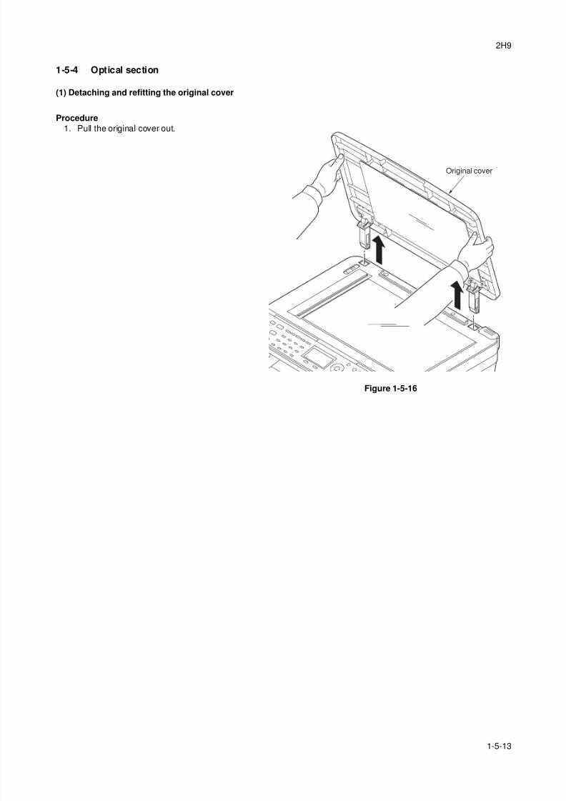
8/3/2019 Servi manualKM-2810ENSMR3
http://slidepdf.com/reader/full/servi-manualkm-2810ensmr3 121/202
2H9
1-5-13
1-5-4 Optical section
(1) Detaching and refitting the original cover
Procedure
1. Pull the original cover out.
Figure 1-5-16
Original cover
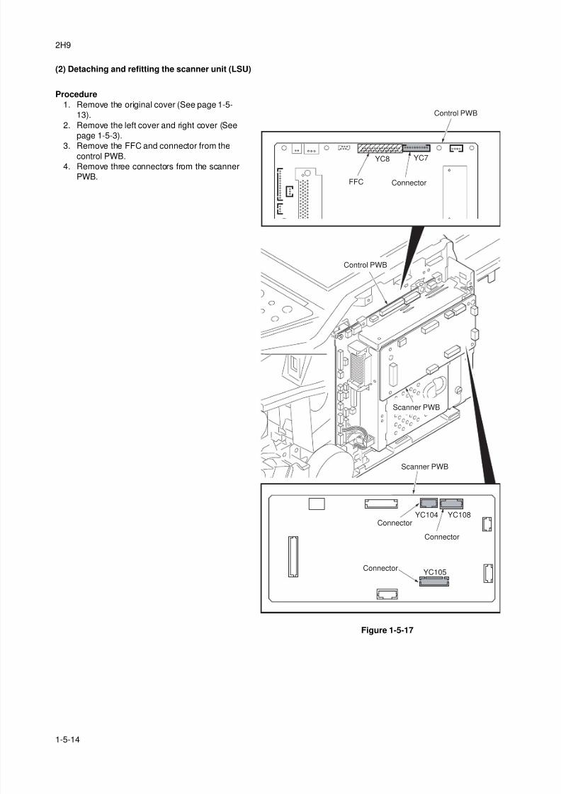
8/3/2019 Servi manualKM-2810ENSMR3
http://slidepdf.com/reader/full/servi-manualkm-2810ensmr3 122/202
2H9
1-5-14
(2) Detaching and refitting the scanner unit (LSU)
Procedure
1. Remove the original cover (See page 1-5-
13).
2. Remove the left cover and right cover (See
page 1-5-3).3. Remove the FFC and connector from the
control PWB.
4. Remove three connectors from the scanner
PWB.
Figure 1-5-17
ConnectorFFC
Scanner PWB
Scanner PWB
Connector
Connector
Connector
YC8 YC7
YC108YC104
YC105
Control PWB
Control PWB
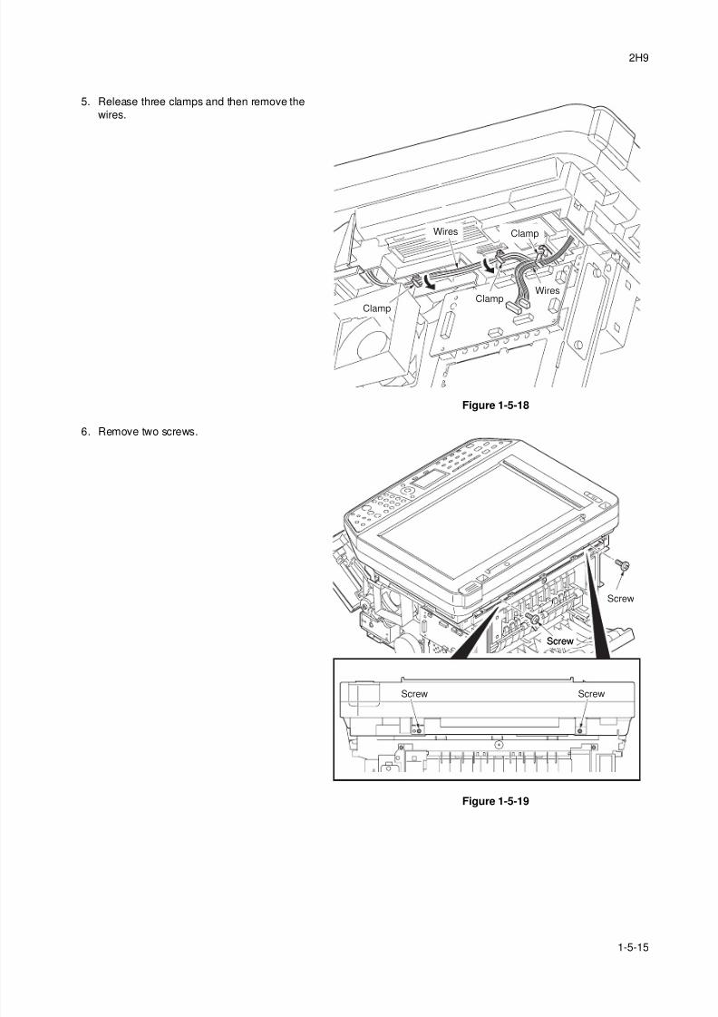
8/3/2019 Servi manualKM-2810ENSMR3
http://slidepdf.com/reader/full/servi-manualkm-2810ensmr3 123/202
2H9
1-5-15
5. Release three clamps and then remove the
wires.
Figure 1-5-18
6. Remove two screws.
Figure 1-5-19
Wires
Wires
Clamp
ClampClamp
Screw Screw
Screw
ScrewScrew
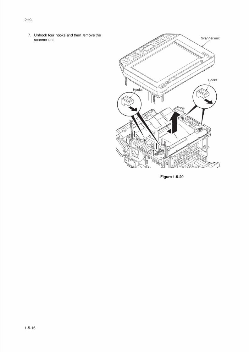
8/3/2019 Servi manualKM-2810ENSMR3
http://slidepdf.com/reader/full/servi-manualkm-2810ensmr3 124/202
2H9
1-5-16
7. Unhook four hooks and then remove the
scanner unit.
Figure 1-5-20
Scanner unit
Hooks
Hooks
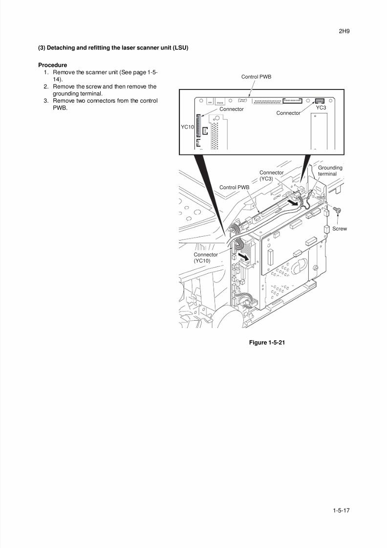
8/3/2019 Servi manualKM-2810ENSMR3
http://slidepdf.com/reader/full/servi-manualkm-2810ensmr3 125/202
2H9
1-5-17
(3) Detaching and refitting the laser scanner unit (LSU)
Procedure
1. Remove the scanner unit (See page 1-5-
14).
2. Remove the screw and then remove the
grounding terminal.3. Remove two connectors from the control
PWB.
Figure 1-5-21
Control PWB
ConnectorConnector
YC3
YC10
Screw
Groundingterminal
Connector(YC10)
Connector(YC3)
Control PWB
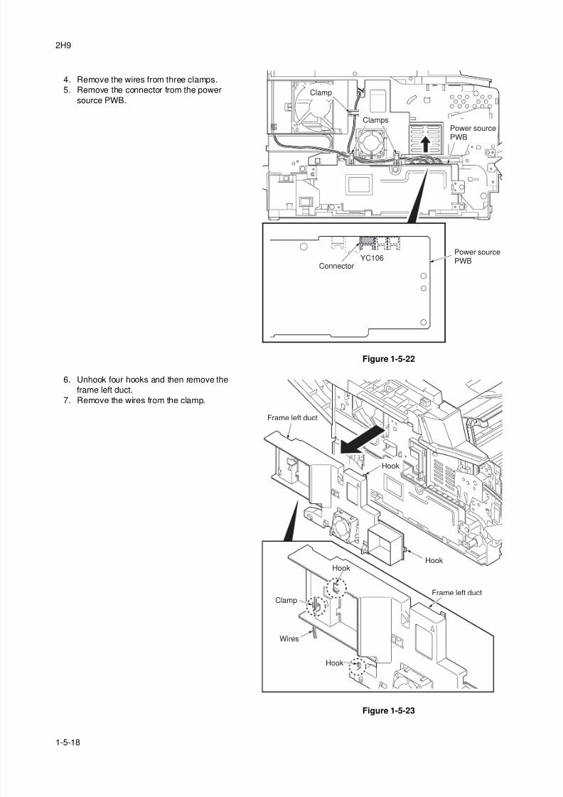
8/3/2019 Servi manualKM-2810ENSMR3
http://slidepdf.com/reader/full/servi-manualkm-2810ensmr3 126/202
2H9
1-5-18
4. Remove the wires from three clamps.
5. Remove the connector from the power
source PWB.
Figure 1-5-22
6. Unhook four hooks and then remove the
frame left duct.
7. Remove the wires from the clamp.
Figure 1-5-23
Clamp
Clamps
Connector
Power source
PWB
Power sourcePWBYC106
Frame left duct
Frame left duct
HookHook
Clamp
Wires
Hook
Hook
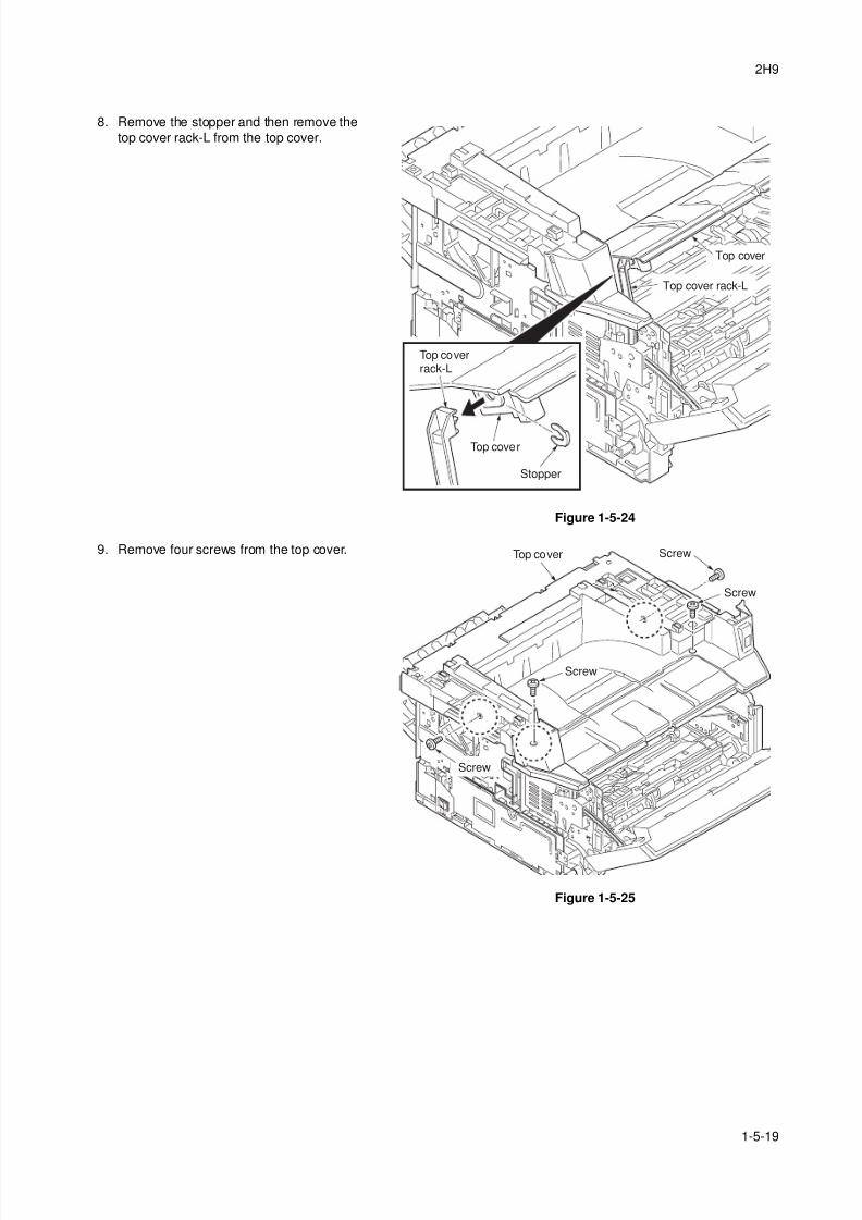
8/3/2019 Servi manualKM-2810ENSMR3
http://slidepdf.com/reader/full/servi-manualkm-2810ensmr3 127/202
2H9
1-5-19
8. Remove the stopper and then remove the
top cover rack-L from the top cover.
Figure 1-5-24
9. Remove four screws from the top cover.
Figure 1-5-25
Top coverrack-L
Stopper
Top cover
Top cover
Top cover rack-L
Top cover Screw
Screw
Screw
Screw
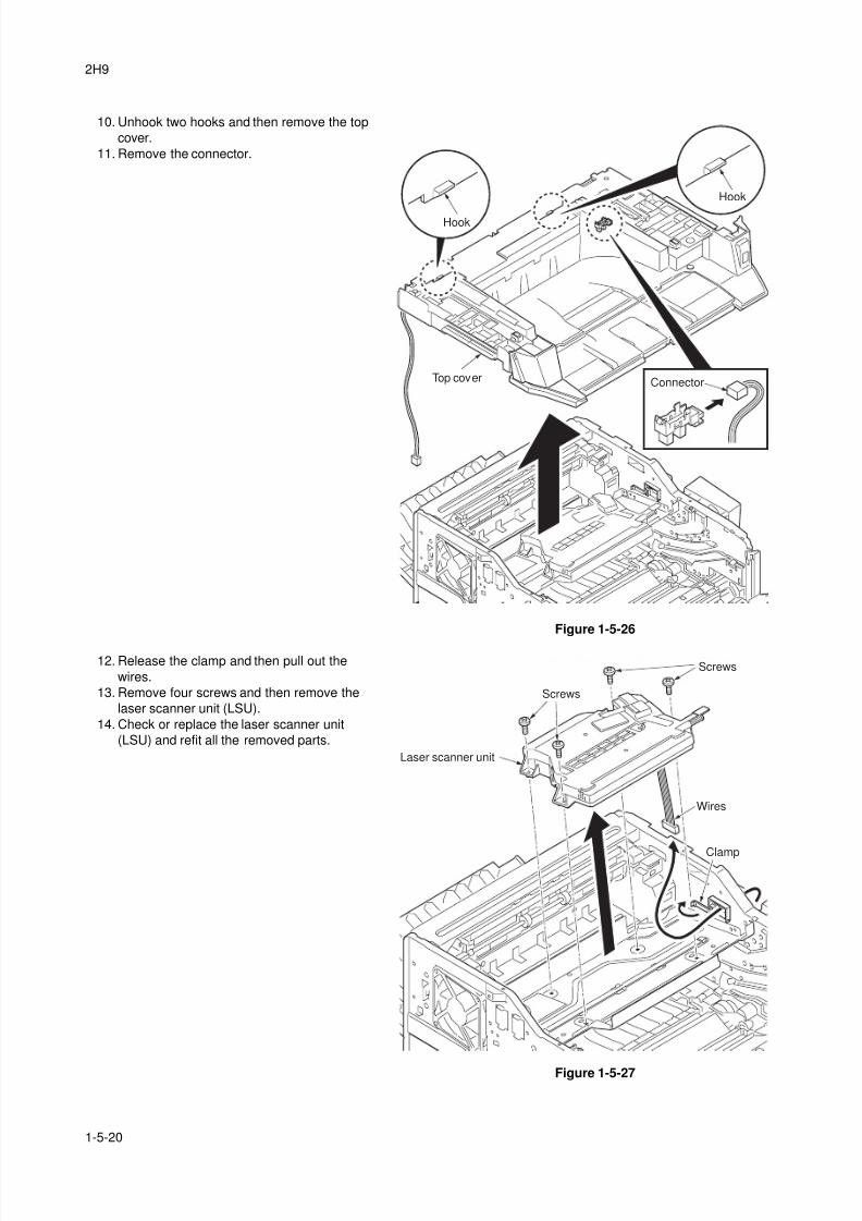
8/3/2019 Servi manualKM-2810ENSMR3
http://slidepdf.com/reader/full/servi-manualkm-2810ensmr3 128/202
2H9
1-5-20
10. Unhook two hooks and then remove the top
cover.
11. Remove the connector.
Figure 1-5-26
12. Release the clamp and then pull out the
wires.
13. Remove four screws and then remove the
laser scanner unit (LSU).
14. Check or replace the laser scanner unit
(LSU) and refit all the removed parts.
Figure 1-5-27
Top cover Connector
Hook
Hook
Laser scanner unit
Wires
Clamp
Screws
Screws
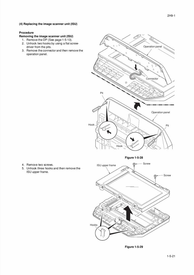
8/3/2019 Servi manualKM-2810ENSMR3
http://slidepdf.com/reader/full/servi-manualkm-2810ensmr3 129/202
2H9-1
1-5-21
(4) Replacing the image scanner unit (ISU)
Procedure
Removing the image scanner unit (ISU)
1. Remove the DP (See page 1-5-13).
2. Unhook two hooks by using a flat screw-
driver from the pits.3. Remove the connector and then remove the
operation panel.
Figure 1-5-28
4. Remove two screws.
5. Unhook three hooks and then remove the
ISU upper frame.
Figure 1-5-29
Hook
Pit
Pit
Connector
Operation panel
Operation panel
Hook
ISU upper frameScrew
Screw
Hooks
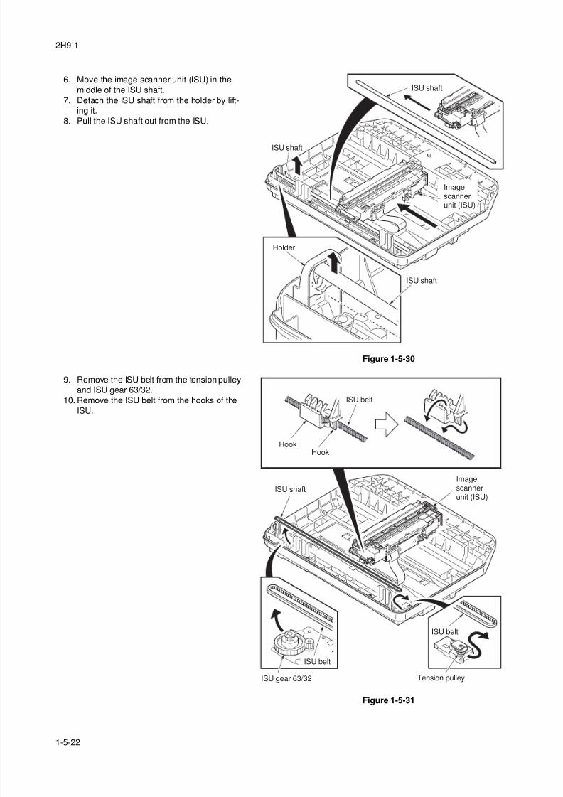
8/3/2019 Servi manualKM-2810ENSMR3
http://slidepdf.com/reader/full/servi-manualkm-2810ensmr3 130/202
2H9-1
1-5-22
6. Move the image scanner unit (ISU) in the
middle of the ISU shaft.
7. Detach the ISU shaft from the holder by lift-
ing it.
8. Pull the ISU shaft out from the ISU.
Figure 1-5-30
9. Remove the ISU belt from the tension pulley
and ISU gear 63/32.
10. Remove the ISU belt from the hooks of the
ISU.
Figure 1-5-31
ISU shaft
ISU shaft
ISU shaft
Holder
Imagescannerunit (ISU)
ISU gear 63/32 Tension pulley
Imagescannerunit (ISU)
ISU shaft
ISU belt
ISU belt
ISU belt
HookHook
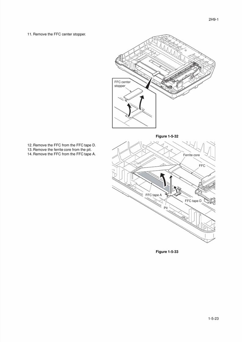
8/3/2019 Servi manualKM-2810ENSMR3
http://slidepdf.com/reader/full/servi-manualkm-2810ensmr3 131/202
2H9-1
1-5-23
11. Remove the FFC center stopper.
Figure 1-5-32
12. Remove the FFC from the FFC tape D.
13. Remove the ferrite core from the pit.
14. Remove the FFC from the FFC tape A.
Figure 1-5-33
FFC centerstopper
Ferrite core
FFC tape A
Pit
FFC
FFC tape D
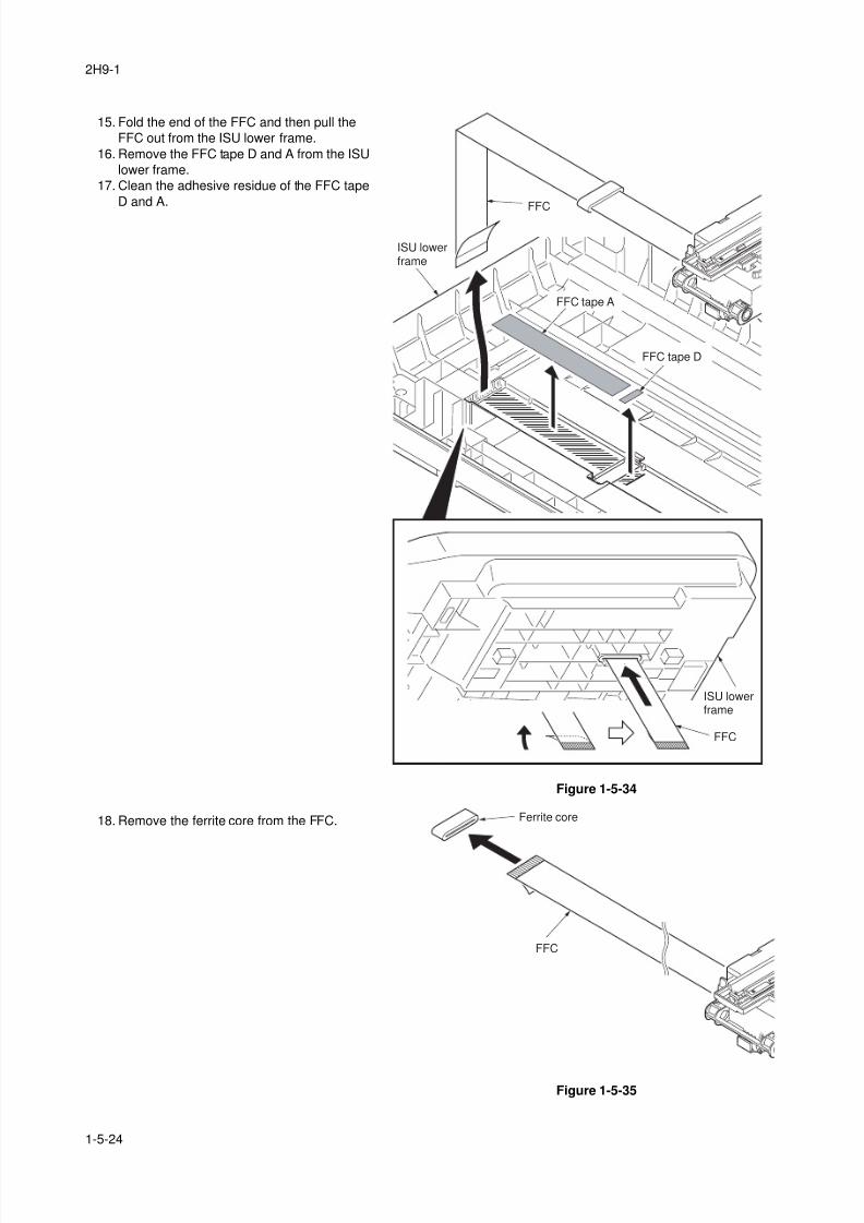
8/3/2019 Servi manualKM-2810ENSMR3
http://slidepdf.com/reader/full/servi-manualkm-2810ensmr3 132/202
2H9-1
1-5-24
15. Fold the end of the FFC and then pull the
FFC out from the ISU lower frame.
16. Remove the FFC tape D and A from the ISU
lower frame.
17. Clean the adhesive residue of the FFC tape
D and A.
Figure 1-5-34
18. Remove the ferrite core from the FFC.
Figure 1-5-35
FFC
FFC
ISU lowerframe
ISU lowerframe
FFC tape A
FFC tape D
Ferrite core
FFC
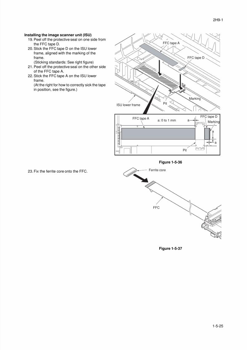
8/3/2019 Servi manualKM-2810ENSMR3
http://slidepdf.com/reader/full/servi-manualkm-2810ensmr3 133/202
2H9-1
1-5-25
Installing the image scanner unit (ISU)
19. Peel off the protective seal on one side from
the FFC tape D.
20. Stick the FFC tape D on the ISU lower
frame, aligned with the marking of the
frame.
(Sticking standards: See right figure)21. Peel off the protective seal on the other side
of the FFC tape A.
22. Stick the FFC tape A on the ISU lower
frame.
(At the right for how to correctly sick the tape
in position, see the figure.)
Figure 1-5-36
23. Fix the ferrite core onto the FFC.
Figure 1-5-37
a
aa: 0 to 1 mm
a
FFC tape A
FFC tape A
FFC tape D
Pit
Pit
FFC tape D
Marking
Marking
ISU lower frame
Ferrite core
FFC
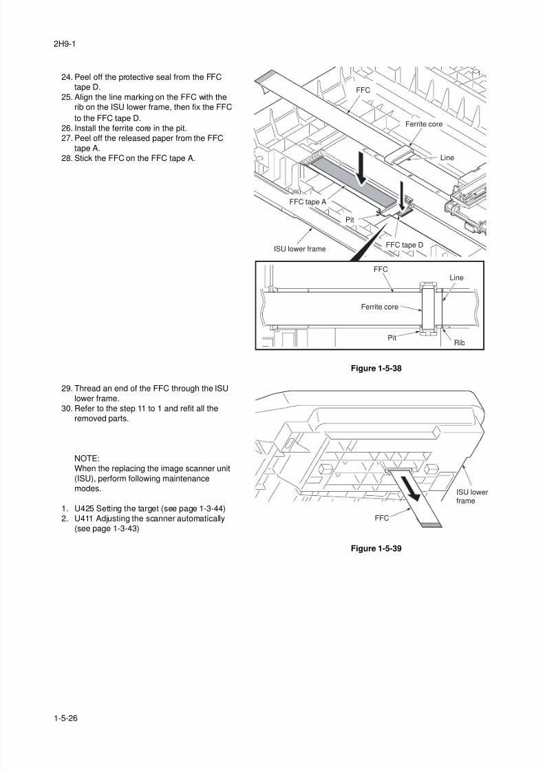
8/3/2019 Servi manualKM-2810ENSMR3
http://slidepdf.com/reader/full/servi-manualkm-2810ensmr3 134/202
2H9-1
1-5-26
24. Peel off the protective seal from the FFC
tape D.
25. Align the line marking on the FFC with the
rib on the ISU lower frame, then fix the FFC
to the FFC tape D.
26. Install the ferrite core in the pit.
27. Peel off the released paper from the FFCtape A.
28. Stick the FFC on the FFC tape A.
Figure 1-5-38
29. Thread an end of the FFC through the ISU
lower frame.
30. Refer to the step 11 to 1 and refit all theremoved parts.
NOTE:
When the replacing the image scanner unit
(ISU), perform following maintenance
modes.
1. U425 Setting the target (see page 1-3-44)
2. U411 Adjusting the scanner automatically
(see page 1-3-43)
Figure 1-5-39
Ferrite core
Ferrite core
FFC tape A
Pit
Pit
FFC
FFC tape DISU lower frame
FFCLine
Rib
Line
FFC
ISU lowerframe
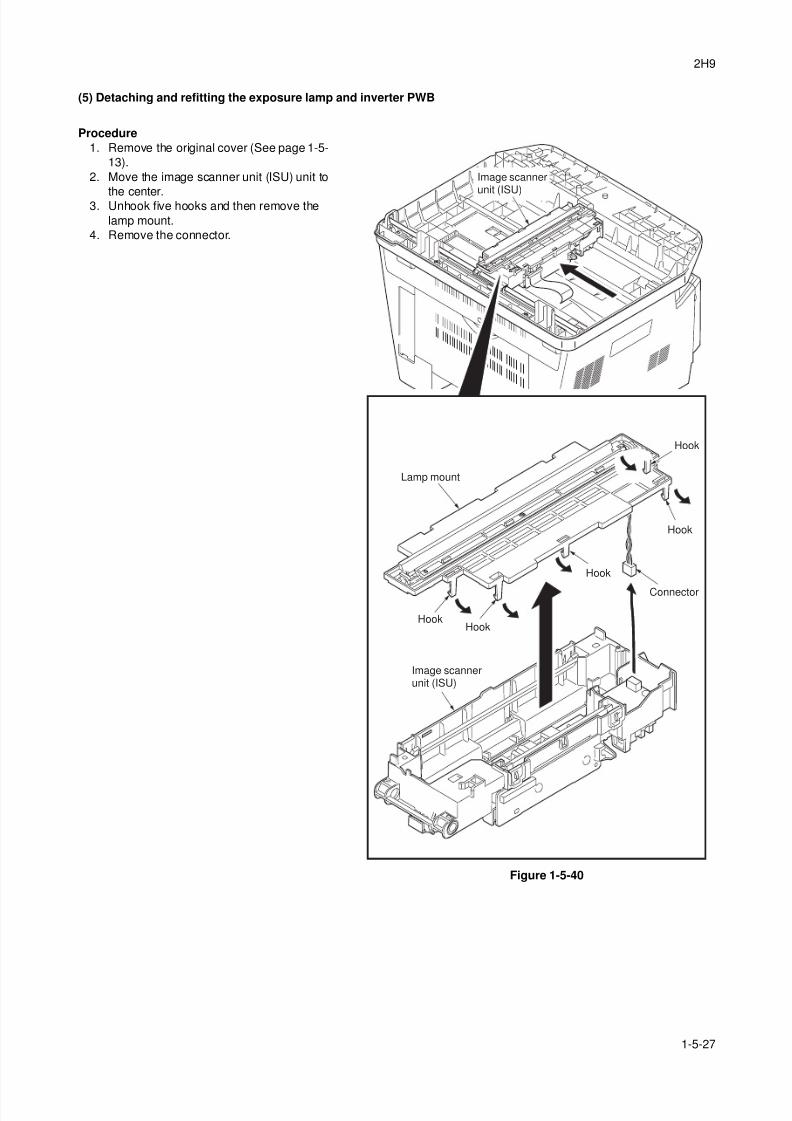
8/3/2019 Servi manualKM-2810ENSMR3
http://slidepdf.com/reader/full/servi-manualkm-2810ensmr3 135/202
2H9
1-5-27
(5) Detaching and refitting the exposure lamp and inverter PWB
Procedure
1. Remove the original cover (See page 1-5-
13).
2. Move the image scanner unit (ISU) unit to
the center.3. Unhook five hooks and then remove the
lamp mount.
4. Remove the connector.
Figure 1-5-40
HookHook
Hook
Hook
Hook
Lamp mount
Connector
Image scannerunit (ISU)
Image scannerunit (ISU)
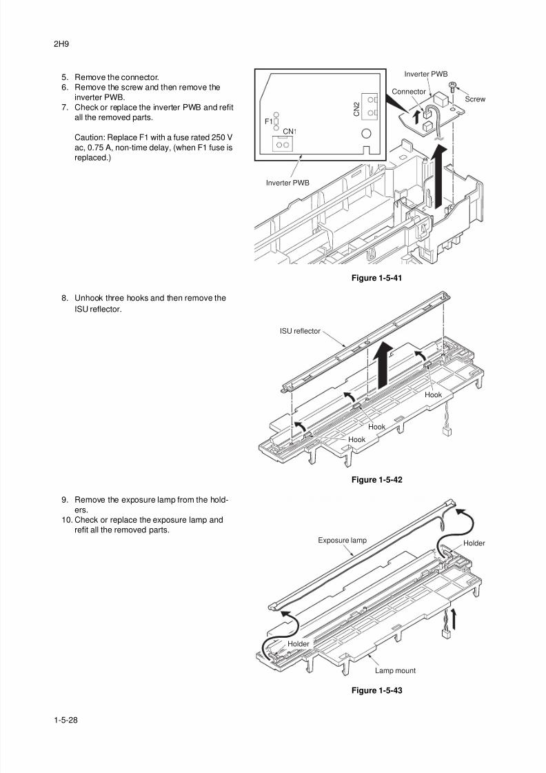
8/3/2019 Servi manualKM-2810ENSMR3
http://slidepdf.com/reader/full/servi-manualkm-2810ensmr3 136/202
2H9
1-5-28
5. Remove the connector.
6. Remove the screw and then remove the
inverter PWB.
7. Check or replace the inverter PWB and refit
all the removed parts.
Caution: Replace F1 with a fuse rated 250 Vac, 0.75 A, non-time delay, (when F1 fuse is
replaced.)
Figure 1-5-41
8. Unhook three hooks and then remove the
ISU reflector.
Figure 1-5-42
9. Remove the exposure lamp from the hold-
ers.
10. Check or replace the exposure lamp and
refit all the removed parts.
Figure 1-5-43
Inverter PWB
Inverter PWB
ScrewConnector
C N 2
CN1
F1
ISU reflector
Hook
Hook
Hook
Holder
Holder
Exposure lamp
Lamp mount
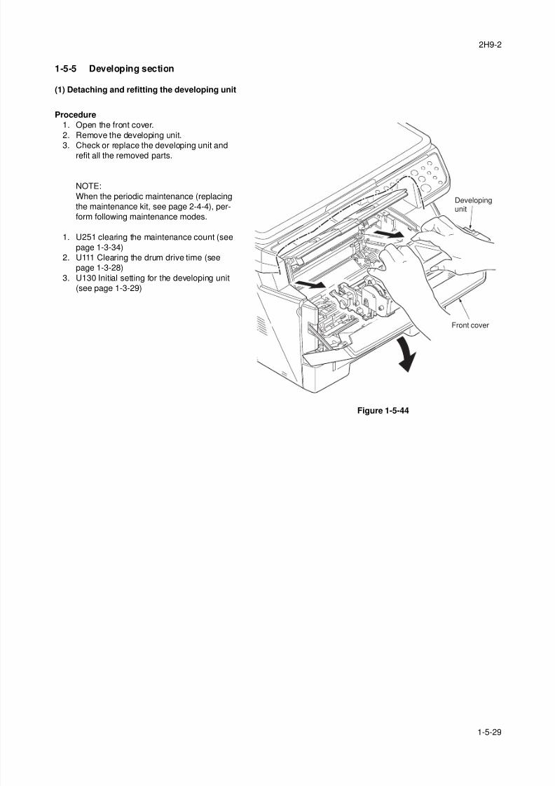
8/3/2019 Servi manualKM-2810ENSMR3
http://slidepdf.com/reader/full/servi-manualkm-2810ensmr3 137/202
2H9-2
1-5-29
1-5-5 Developing section
(1) Detaching and refitting the developing unit
Procedure
1. Open the front cover.
2. Remove the developing unit.3. Check or replace the developing unit and
refit all the removed parts.
NOTE:
When the periodic maintenance (replacing
the maintenance kit, see page 2-4-4), per-
form following maintenance modes.
1. U251 clearing the maintenance count (see
page 1-3-34)
2. U111 Clearing the drum drive time (see
page 1-3-28)
3. U130 Initial setting for the developing unit(see page 1-3-29)
Figure 1-5-44
Developingunit
Front cover
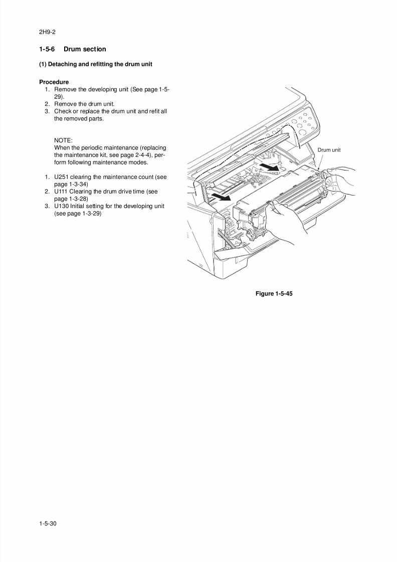
8/3/2019 Servi manualKM-2810ENSMR3
http://slidepdf.com/reader/full/servi-manualkm-2810ensmr3 138/202
2H9-2
1-5-30
1-5-6 Drum section
(1) Detaching and refitting the drum unit
Procedure
1. Remove the developing unit (See page 1-5-
29).2. Remove the drum unit.
3. Check or replace the drum unit and refit all
the removed parts.
NOTE:
When the periodic maintenance (replacing
the maintenance kit, see page 2-4-4), per-
form following maintenance modes.
1. U251 clearing the maintenance count (see
page 1-3-34)
2. U111 Clearing the drum drive time (see
page 1-3-28)3. U130 Initial setting for the developing unit
(see page 1-3-29)
Figure 1-5-45
Drum unit
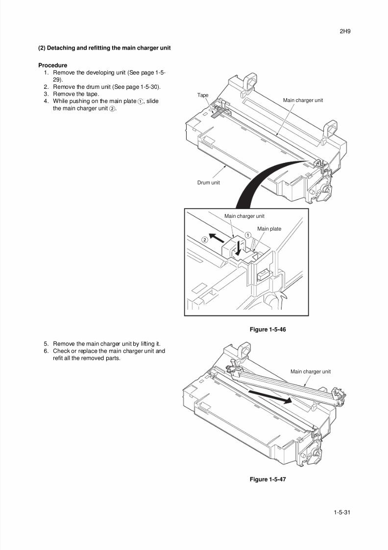
8/3/2019 Servi manualKM-2810ENSMR3
http://slidepdf.com/reader/full/servi-manualkm-2810ensmr3 139/202
2H9
1-5-31
(2) Detaching and refitting the main charger unit
Procedure
1. Remove the developing unit (See page 1-5-
29).
2. Remove the drum unit (See page 1-5-30).
3. Remove the tape.4. While pushing on the main plate, slide
the main charger unit.
Figure 1-5-46
5. Remove the main charger unit by lifting it.
6. Check or replace the main charger unit and
refit all the removed parts.
Figure 1-5-47
Main charger unit
Main charger unit
Tape
Main plate
Drum unit
Main charger unit
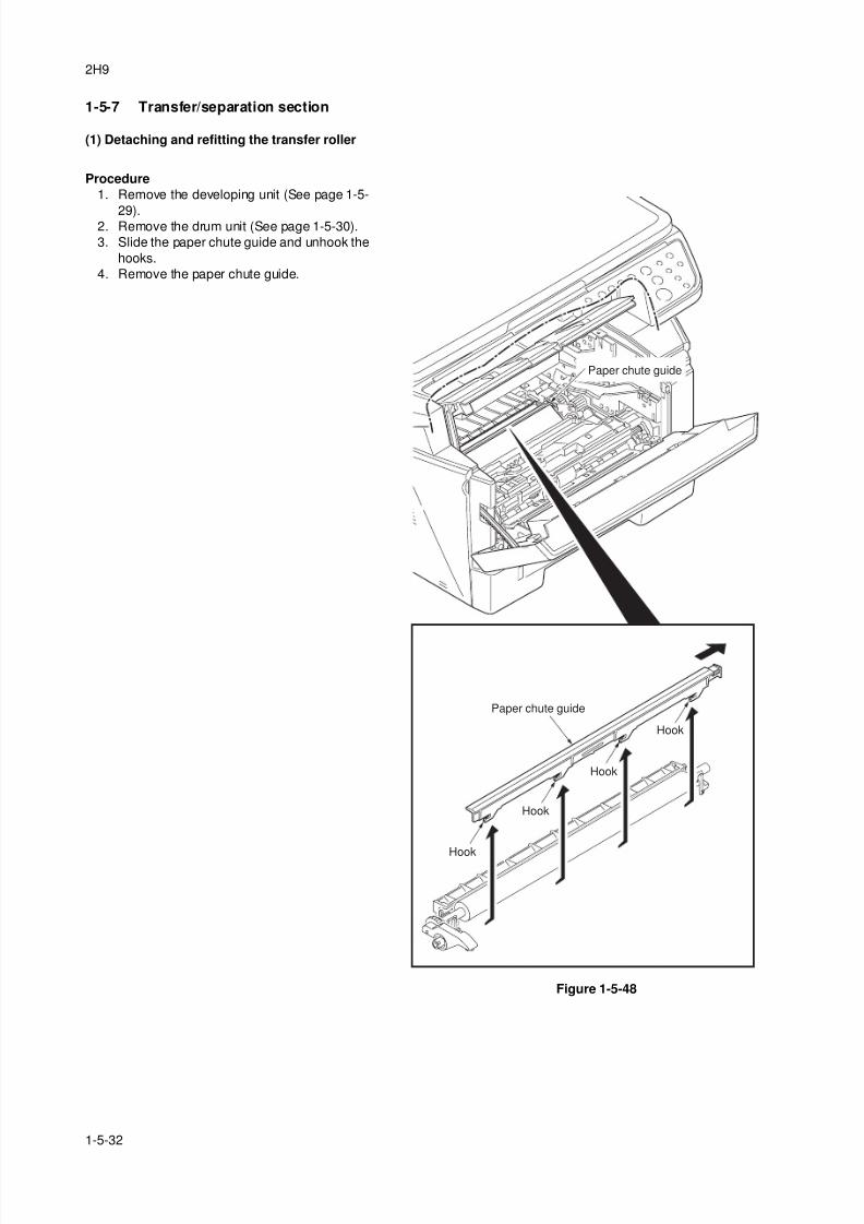
8/3/2019 Servi manualKM-2810ENSMR3
http://slidepdf.com/reader/full/servi-manualkm-2810ensmr3 140/202
2H9
1-5-32
1-5-7 Transfer/separation section
(1) Detaching and refitting the transfer roller
Procedure
1. Remove the developing unit (See page 1-5-
29).2. Remove the drum unit (See page 1-5-30).
3. Slide the paper chute guide and unhook the
hooks.
4. Remove the paper chute guide.
Figure 1-5-48
Paper chute guide
Paper chute guide
Hook
Hook
Hook
Hook
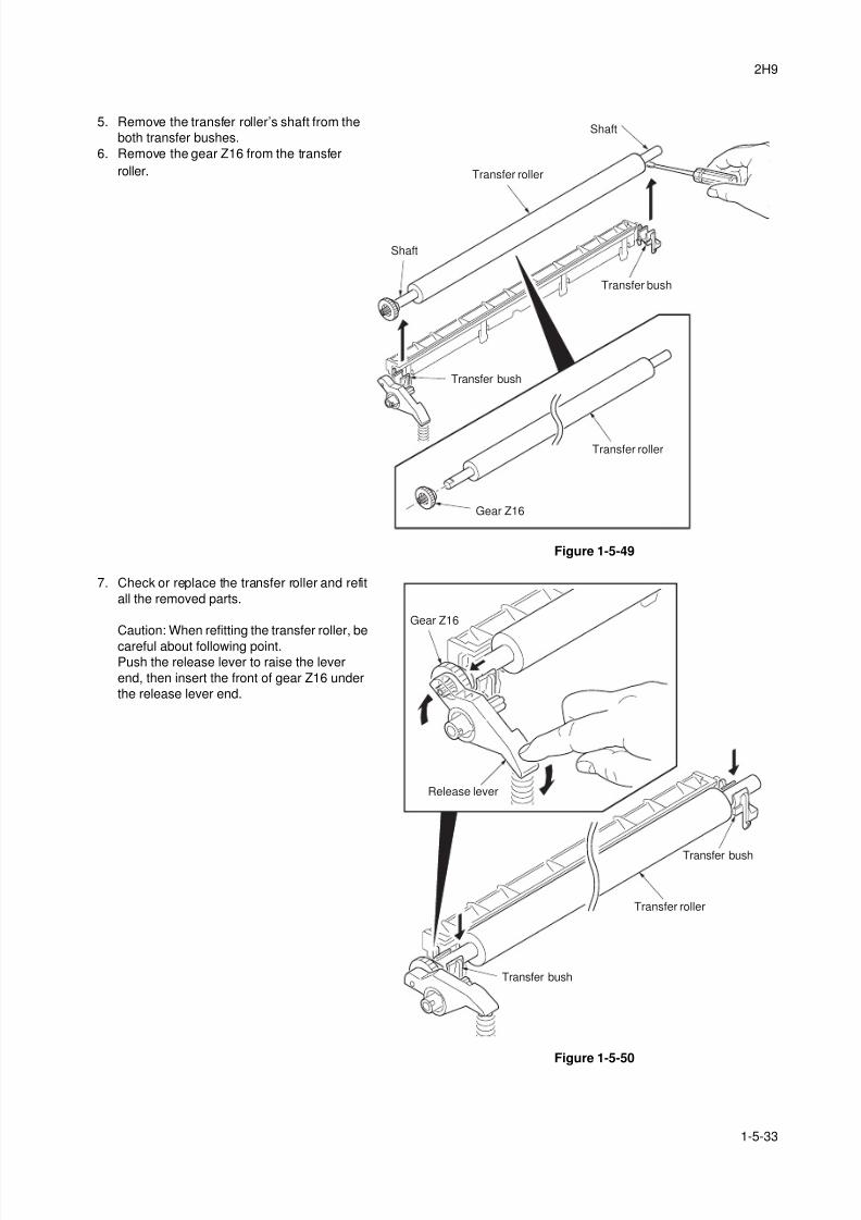
8/3/2019 Servi manualKM-2810ENSMR3
http://slidepdf.com/reader/full/servi-manualkm-2810ensmr3 141/202
2H9
1-5-33
5. Remove the transfer roller’s shaft from the
both transfer bushes.
6. Remove the gear Z16 from the transfer
roller.
Figure 1-5-49
7. Check or replace the transfer roller and refit
all the removed parts.
Caution: When refitting the transfer roller, be
careful about following point.Push the release lever to raise the lever
end, then insert the front of gear Z16 under
the release lever end.
Figure 1-5-50
Transfer roller
Shaft
Shaft
Transfer roller
Transfer bush
Transfer bush
Gear Z16
Release lever
Gear Z16
Transfer bush
Transfer bush
Transfer roller
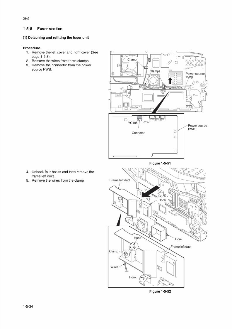
8/3/2019 Servi manualKM-2810ENSMR3
http://slidepdf.com/reader/full/servi-manualkm-2810ensmr3 142/202
2H9
1-5-34
1-5-8 Fuser section
(1) Detaching and refitting the fuser unit
Procedure
1. Remove the left cover and right cover (See
page 1-5-3).2. Remove the wires from three clamps.
3. Remove the connector from the power
source PWB.
Figure 1-5-51
4. Unhook four hooks and then remove theframe left duct.
5. Remove the wires from the clamp.
Figure 1-5-52
YC105
Clamp
Clamps
Connctor
Power sourcePWB
Power sourcePWB
Frame left duct
Frame left duct
Hook
Clamp
Wires
Hook
Hook
Hook
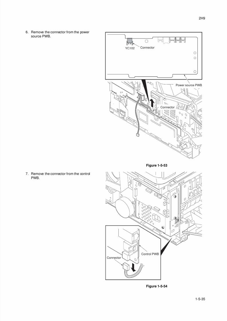
8/3/2019 Servi manualKM-2810ENSMR3
http://slidepdf.com/reader/full/servi-manualkm-2810ensmr3 143/202
2H9
1-5-35
6. Remove the connector from the power
source PWB.
Figure 1-5-53
7. Remove the connector from the control
PWB.
Figure 1-5-54
YC102
Connector
Connector
Power source PWB
Connector
Control PWB
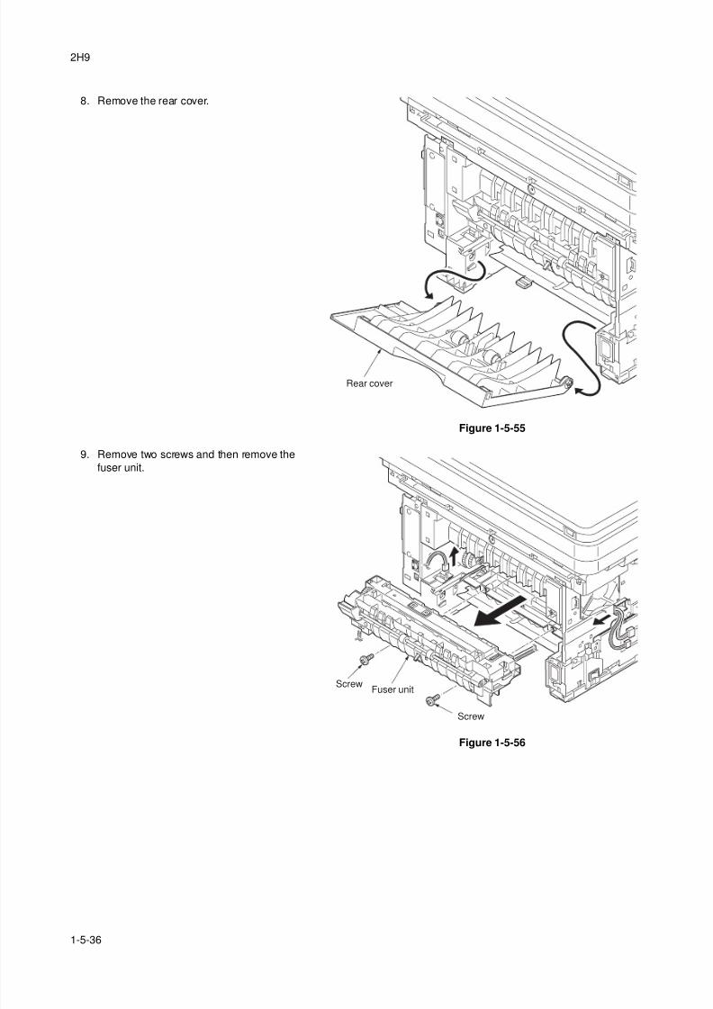
8/3/2019 Servi manualKM-2810ENSMR3
http://slidepdf.com/reader/full/servi-manualkm-2810ensmr3 144/202
2H9
1-5-36
8. Remove the rear cover.
Figure 1-5-55
9. Remove two screws and then remove the
fuser unit.
Figure 1-5-56
Rear cover
Fuser unit
Screw
Screw
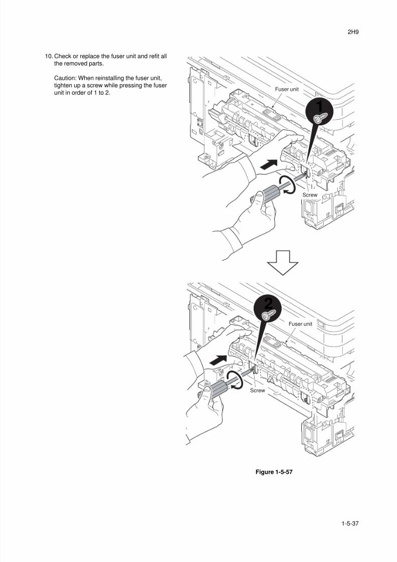
8/3/2019 Servi manualKM-2810ENSMR3
http://slidepdf.com/reader/full/servi-manualkm-2810ensmr3 145/202
2H9
1-5-37
10. Check or replace the fuser unit and refit all
the removed parts.
Caution: When reinstalling the fuser unit,
tighten up a screw while pressing the fuser
unit in order of 1 to 2.
Figure 1-5-57
1
2
Fuser unit
Screw
Screw
Fuser unit
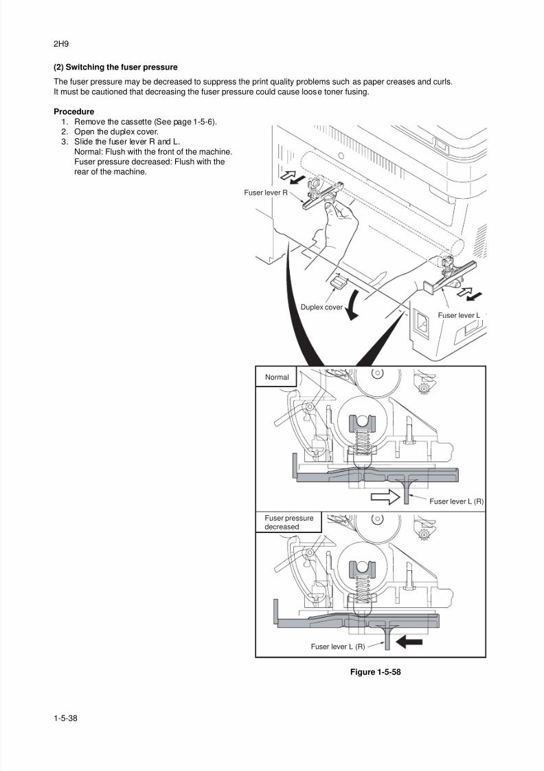
8/3/2019 Servi manualKM-2810ENSMR3
http://slidepdf.com/reader/full/servi-manualkm-2810ensmr3 146/202
2H9
1-5-38
(2) Switching the fuser pressure
The fuser pressure may be decreased to suppress the print quality problems such as paper creases and curls.
It must be cautioned that decreasing the fuser pressure could cause loose toner fusing.
Procedure
1. Remove the cassette (See page 1-5-6).
2. Open the duplex cover.3. Slide the fuser lever R and L.
Normal: Flush with the front of the machine.
Fuser pressure decreased: Flush with the
rear of the machine.
Figure 1-5-58
Fuser lever R
Duplex cover
Fuser lever L (R)
Fuser lever L (R)
Fuser lever L
Normal
Fuser pressuredecreased
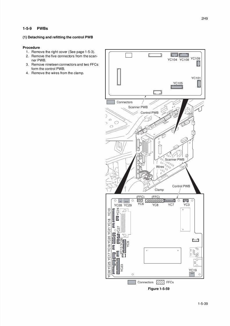
8/3/2019 Servi manualKM-2810ENSMR3
http://slidepdf.com/reader/full/servi-manualkm-2810ensmr3 147/202
2H9
1-5-39
1-5-9 PWBs
(1) Detaching and refitting the control PWB
Procedure
1. Remove the right cover (See page 1-5-3).
2. Remove the five connectors from the scan-ner PWB.
3. Remove nineteen connectors and two FFCs
form the control PWB.
4. Remove the wires from the clamp.
Figure 1-5-59
Scanner PWB
Wires
Clamp
YC29YC28 YC6 YC8 YC7
(FFC)(FFC)
YC3
YC19
Y C 3 0 Y
C 2 3
Y C 2 5 Y C 1 7 Y
C 1 3
Y C 1 6 Y C 2 0
Y C 2
7
Y C 2 1
Y C 1 8
Y C 2 4
Y C 1 0
Y C 2 6
Y C 9
YC101
YC109YC108YC104
YC105
Connectors
FFCsConnectors
Control PWB
Scanner PWB
Control PWB
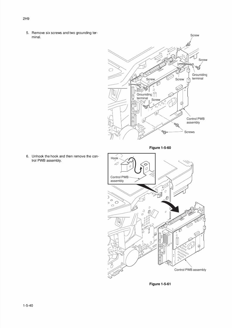
8/3/2019 Servi manualKM-2810ENSMR3
http://slidepdf.com/reader/full/servi-manualkm-2810ensmr3 148/202
2H9
1-5-40
5. Remove six screws and two grounding ter-
minal.
Figure 1-5-60
6. Unhook the hook and then remove the con-
trol PWB assembly.
Figure 1-5-61
Control PWBassembly
Screw
Screw
Screw Screw
Screws
Grounidingterminal
Screw
Grounidingterminal
Control PWB assembly
Control PWBassembly
Hook
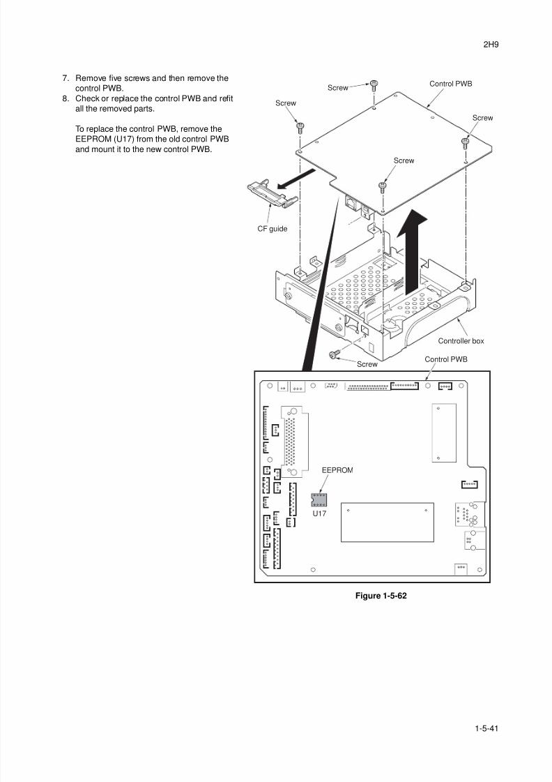
8/3/2019 Servi manualKM-2810ENSMR3
http://slidepdf.com/reader/full/servi-manualkm-2810ensmr3 149/202
2H9
1-5-41
7. Remove five screws and then remove the
control PWB.
8. Check or replace the control PWB and refit
all the removed parts.
To replace the control PWB, remove the
EEPROM (U17) from the old control PWBand mount it to the new control PWB.
Figure 1-5-62
Controller box
Screw
EEPROM
U17
Screw
ScrewControl PWB
Control PWB
Screw
Screw
CF guide
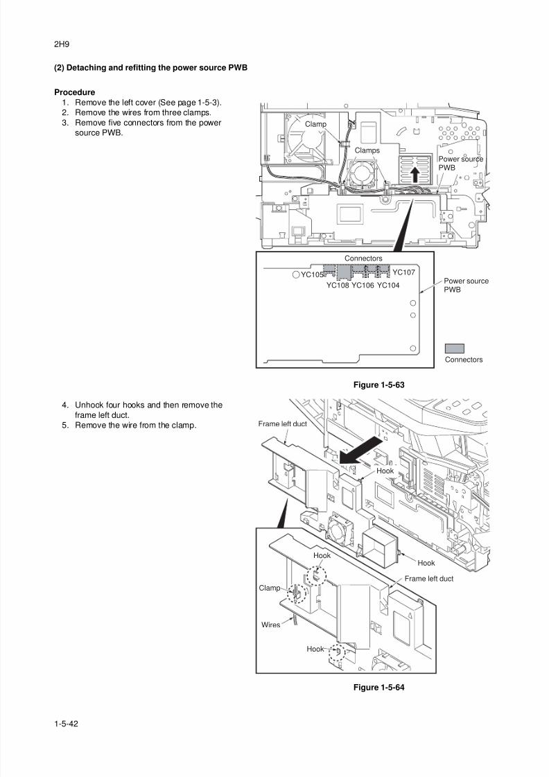
8/3/2019 Servi manualKM-2810ENSMR3
http://slidepdf.com/reader/full/servi-manualkm-2810ensmr3 150/202
2H9
1-5-42
(2) Detaching and refitting the power source PWB
Procedure
1. Remove the left cover (See page 1-5-3).
2. Remove the wires from three clamps.
3. Remove five connectors from the power
source PWB.
Figure 1-5-63
4. Unhook four hooks and then remove theframe left duct.
5. Remove the wire from the clamp.
Figure 1-5-64
YC107
YC104YC106YC108
YC105
Clamp
Clamps
Connectors
Power sourcePWB
Connectors
Power sourcePWB
Frame left duct
Frame left duct
HookHook
Hook
Clamp
Wires
Hook
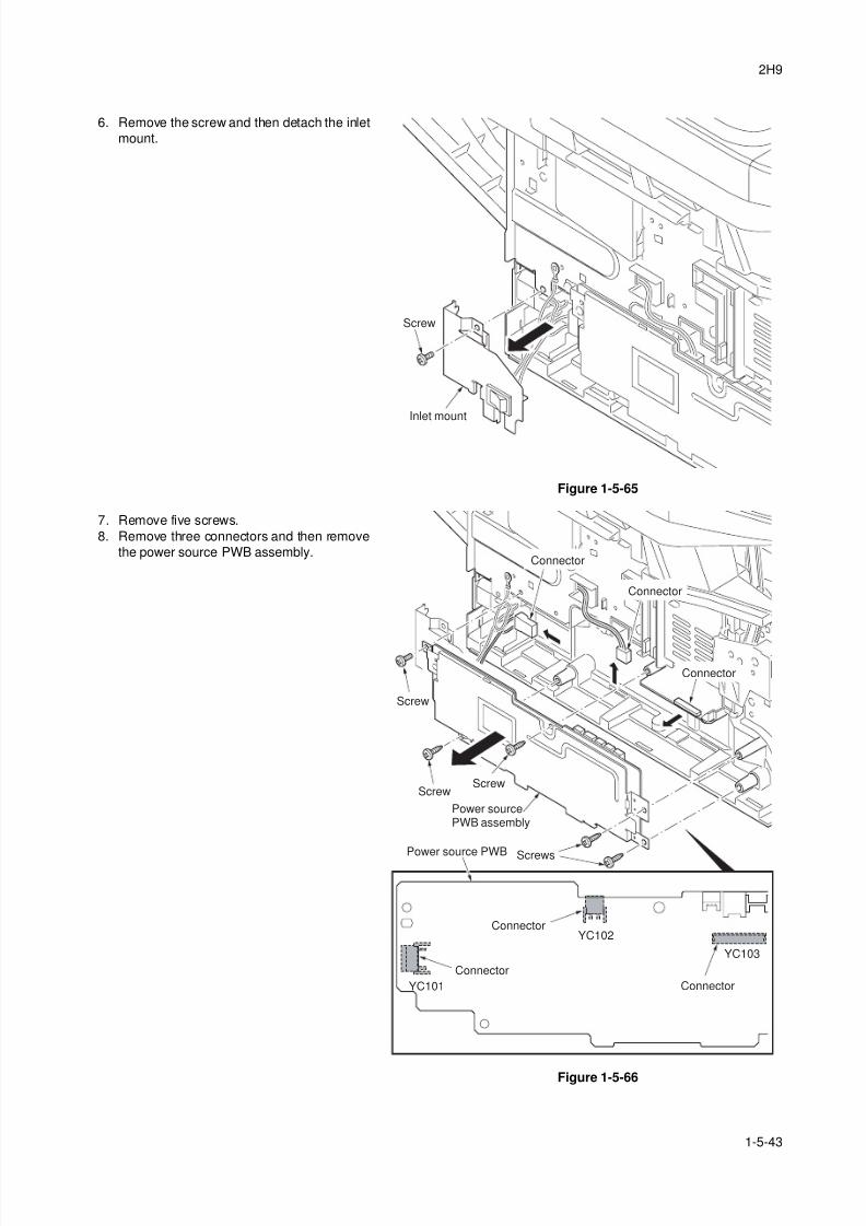
8/3/2019 Servi manualKM-2810ENSMR3
http://slidepdf.com/reader/full/servi-manualkm-2810ensmr3 151/202
2H9
1-5-43
6. Remove the screw and then detach the inlet
mount.
Figure 1-5-65
7. Remove five screws.
8. Remove three connectors and then remove
the power source PWB assembly.
Figure 1-5-66
Inlet mount
Screw
YC103
YC102
YC101
Power source PWB
Power sourcePWB assembly
Connector
Connector
Connector
Screw
Screw
Screw
Screws
Connector
Connector
Connector
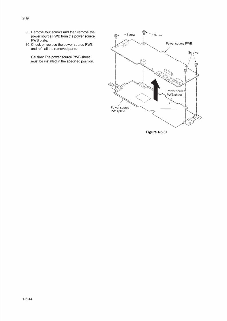
8/3/2019 Servi manualKM-2810ENSMR3
http://slidepdf.com/reader/full/servi-manualkm-2810ensmr3 152/202
2H9
1-5-44
9. Remove four screws and then remove the
power source PWB from the power source
PWB plate.
10. Check or replace the power source PWB
and refit all the removed parts.
Caution: The power source PWB sheetmust be installed in the specified position.
Figure 1-5-67
Screws
Screw
Power source PWB
Power source
PWB plate
Power sourcePWB sheet
Screw
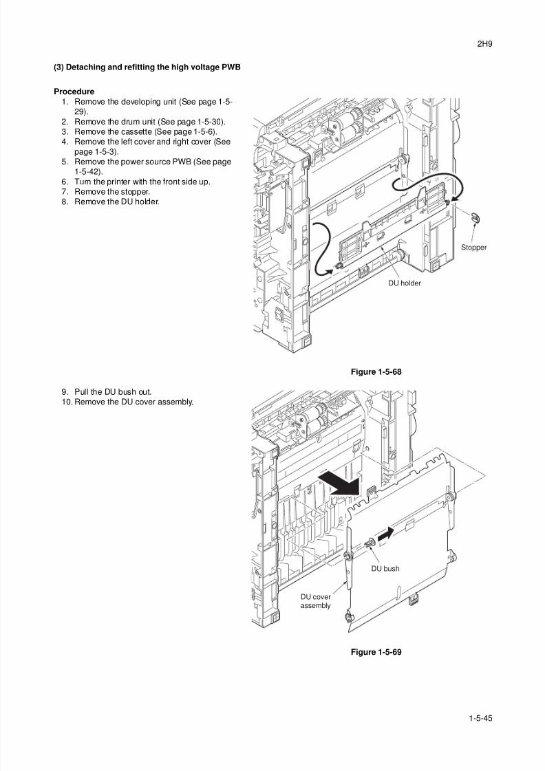
8/3/2019 Servi manualKM-2810ENSMR3
http://slidepdf.com/reader/full/servi-manualkm-2810ensmr3 153/202
2H9
1-5-45
(3) Detaching and refitting the high voltage PWB
Procedure
1. Remove the developing unit (See page 1-5-
29).
2. Remove the drum unit (See page 1-5-30).
3. Remove the cassette (See page 1-5-6).4. Remove the left cover and right cover (See
page 1-5-3).
5. Remove the power source PWB (See page
1-5-42).
6. Turn the printer with the front side up.
7. Remove the stopper.
8. Remove the DU holder.
Figure 1-5-68
9. Pull the DU bush out.
10. Remove the DU cover assembly.
Figure 1-5-69
DU holder
Stopper
DU bush
DU coverassembly
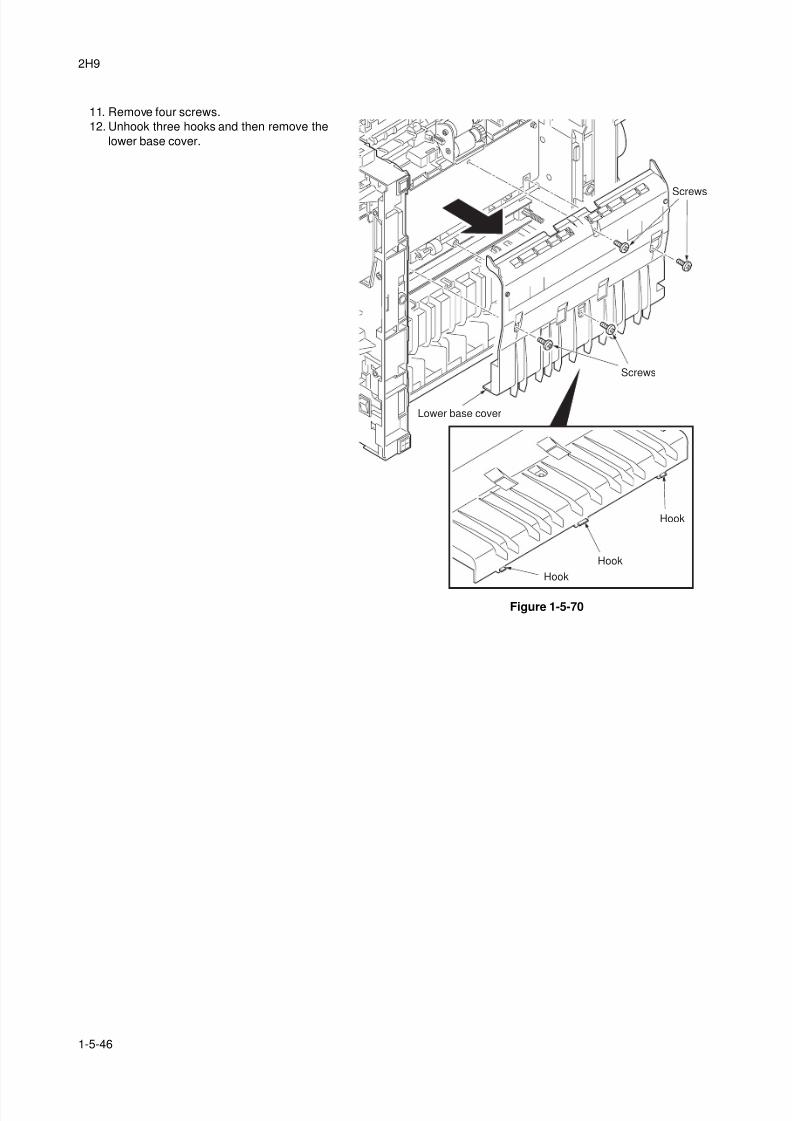
8/3/2019 Servi manualKM-2810ENSMR3
http://slidepdf.com/reader/full/servi-manualkm-2810ensmr3 154/202
2H9
1-5-46
11. Remove four screws.
12. Unhook three hooks and then remove the
lower base cover.
Figure 1-5-70
Screws
Screws
Hook
Hook
Hook
Lower base cover
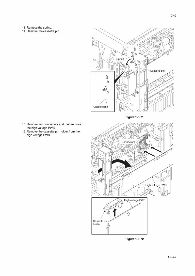
8/3/2019 Servi manualKM-2810ENSMR3
http://slidepdf.com/reader/full/servi-manualkm-2810ensmr3 155/202
2H9
1-5-47
13. Remove the spring.
14. Remove the cassette pin.
Figure 1-5-71
15. Remove two connectors and then remove
the high voltage PWB.
16. Remove the cassette pin holder from the
high voltage PWB.
Figure 1-5-72
Spring
Cassette pin
Cassette pin
Cassette pinholder
High voltage PWB
High voltage PWB
Connectors
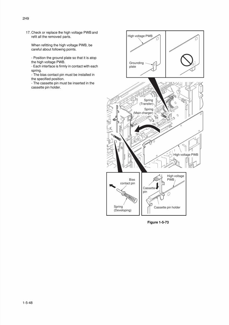
8/3/2019 Servi manualKM-2810ENSMR3
http://slidepdf.com/reader/full/servi-manualkm-2810ensmr3 156/202
2H9
1-5-48
17. Check or replace the high voltage PWB and
refit all the removed parts.
When refitting the high voltage PWB, be
careful about following points.
- Position the ground plate so that it is atopthe high voltage PWB.
- Each interface is firmly in contact with each
spring.
- The bias contact pin must be installed in
the specified position.
- The cassette pin must be inserted in the
cassette pin holder.
Figure 1-5-73
Cassettepin
Cassette pin holder
High voltage PWB
High voltagePWB
High voltage PWB
Groundingplate
Biascontact pin
Spring
(Main charger)
Spring(Developing)
Spring(Transfer)
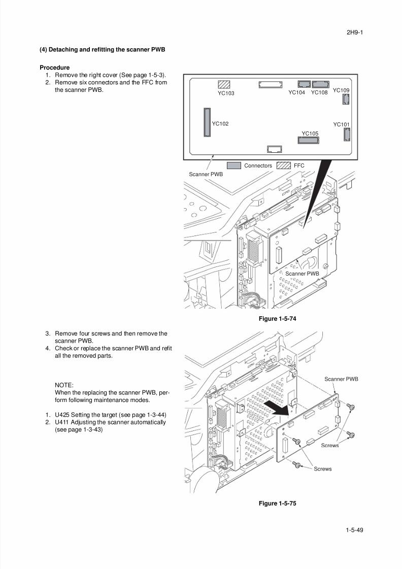
8/3/2019 Servi manualKM-2810ENSMR3
http://slidepdf.com/reader/full/servi-manualkm-2810ensmr3 157/202
2H9-1
1-5-49
(4) Detaching and refitting the scanner PWB
Procedure
1. Remove the right cover (See page 1-5-3).
2. Remove six connectors and the FFC from
the scanner PWB.
Figure 1-5-74
3. Remove four screws and then remove the
scanner PWB.
4. Check or replace the scanner PWB and refit
all the removed parts.
NOTE:
When the replacing the scanner PWB, per-
form following maintenance modes.
1. U425 Setting the target (see page 1-3-44)
2. U411 Adjusting the scanner automatically
(see page 1-3-43)
Figure 1-5-75
YC102
YC103
FFCConnectors
Scanner PWB
Scanner PWB
YC101
YC109YC108YC104
YC105
Scanner PWB
Screws
Screws
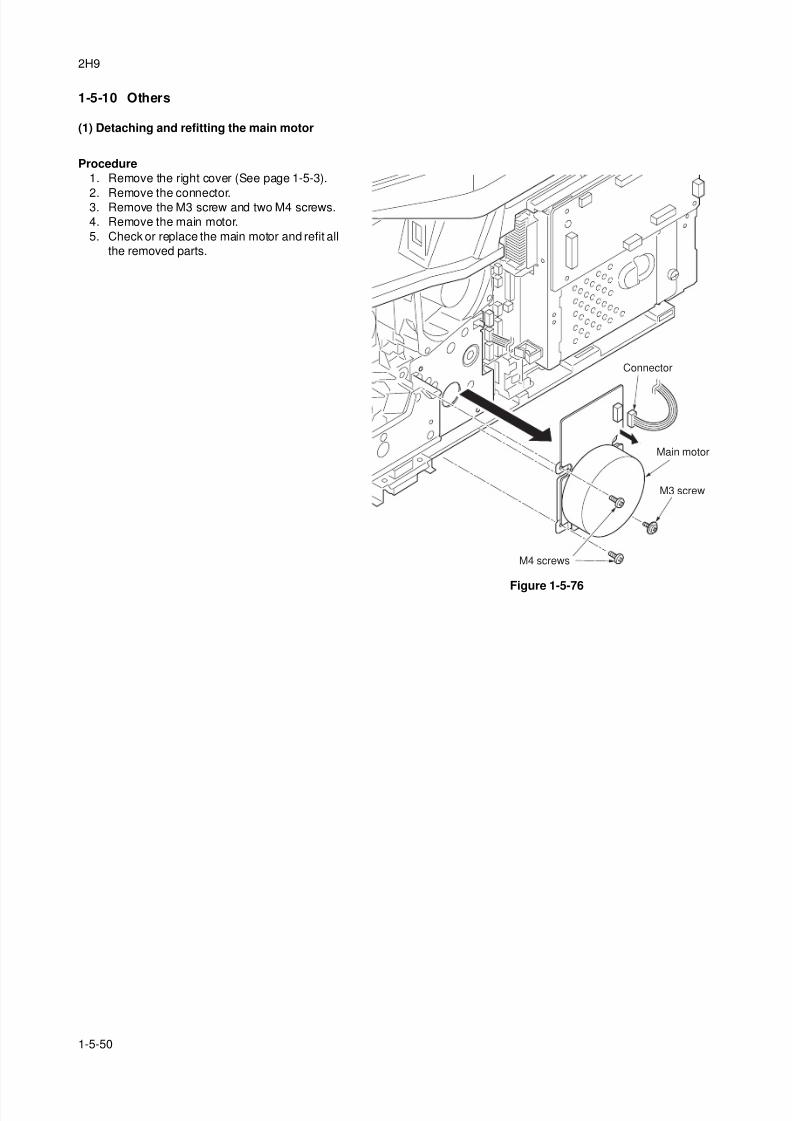
8/3/2019 Servi manualKM-2810ENSMR3
http://slidepdf.com/reader/full/servi-manualkm-2810ensmr3 158/202
2H9
1-5-50
1-5-10 Others
(1) Detaching and refitting the main motor
Procedure
1. Remove the right cover (See page 1-5-3).
2. Remove the connector.3. Remove the M3 screw and two M4 screws.
4. Remove the main motor.
5. Check or replace the main motor and refit all
the removed parts.
Figure 1-5-76
Main motor
Connector
M3 screw
M4 screws
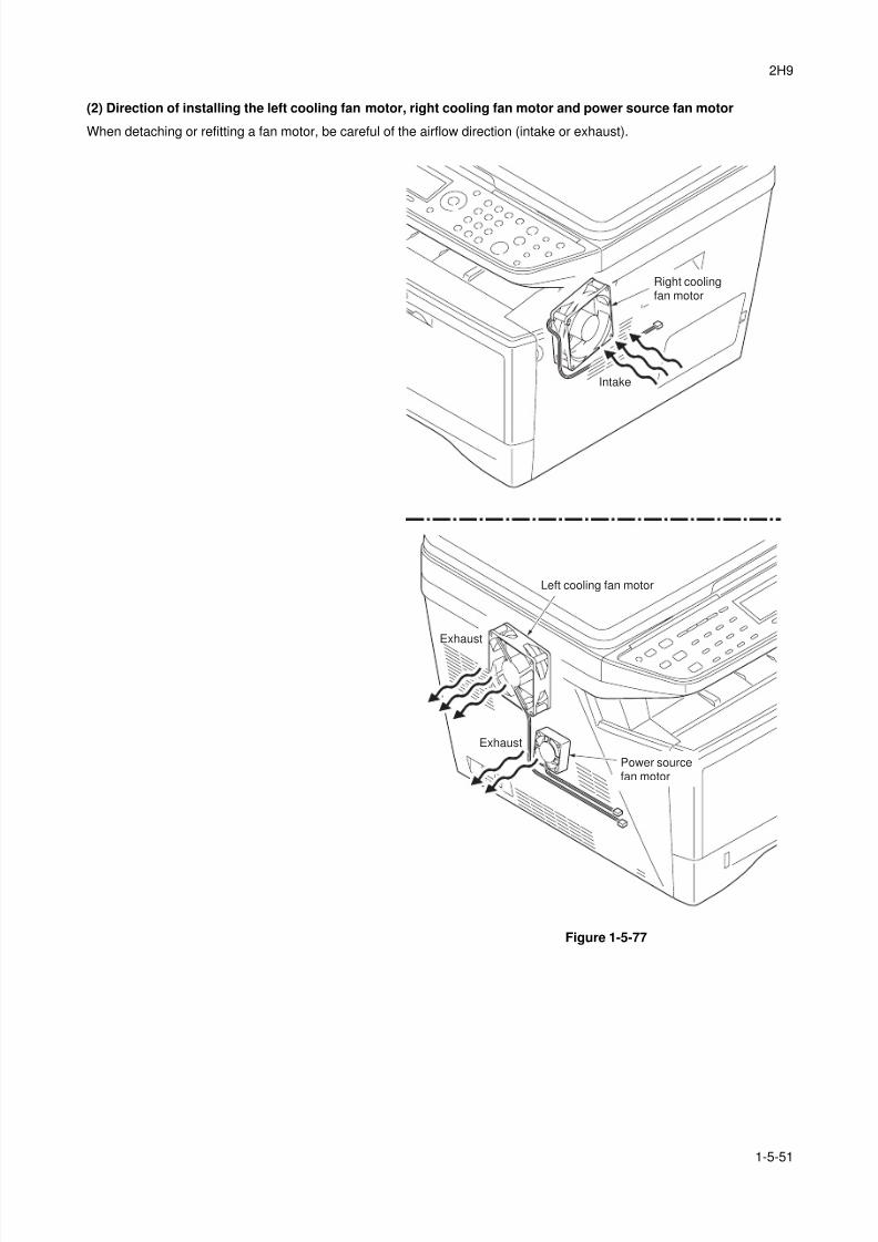
8/3/2019 Servi manualKM-2810ENSMR3
http://slidepdf.com/reader/full/servi-manualkm-2810ensmr3 159/202
2H9
1-5-51
(2) Direction of installing the left cooling fan motor, right cooling fan motor and power source fan motor
When detaching or refitting a fan motor, be careful of the airflow direction (intake or exhaust).
Figure 1-5-77
Left cooling fan motor
Power sourcefan motor
Right coolingfan motor
Exhaust
Exhaust
Intake

8/3/2019 Servi manualKM-2810ENSMR3
http://slidepdf.com/reader/full/servi-manualkm-2810ensmr3 160/202
2H9
1-5-52
This page is intentionally left blank.
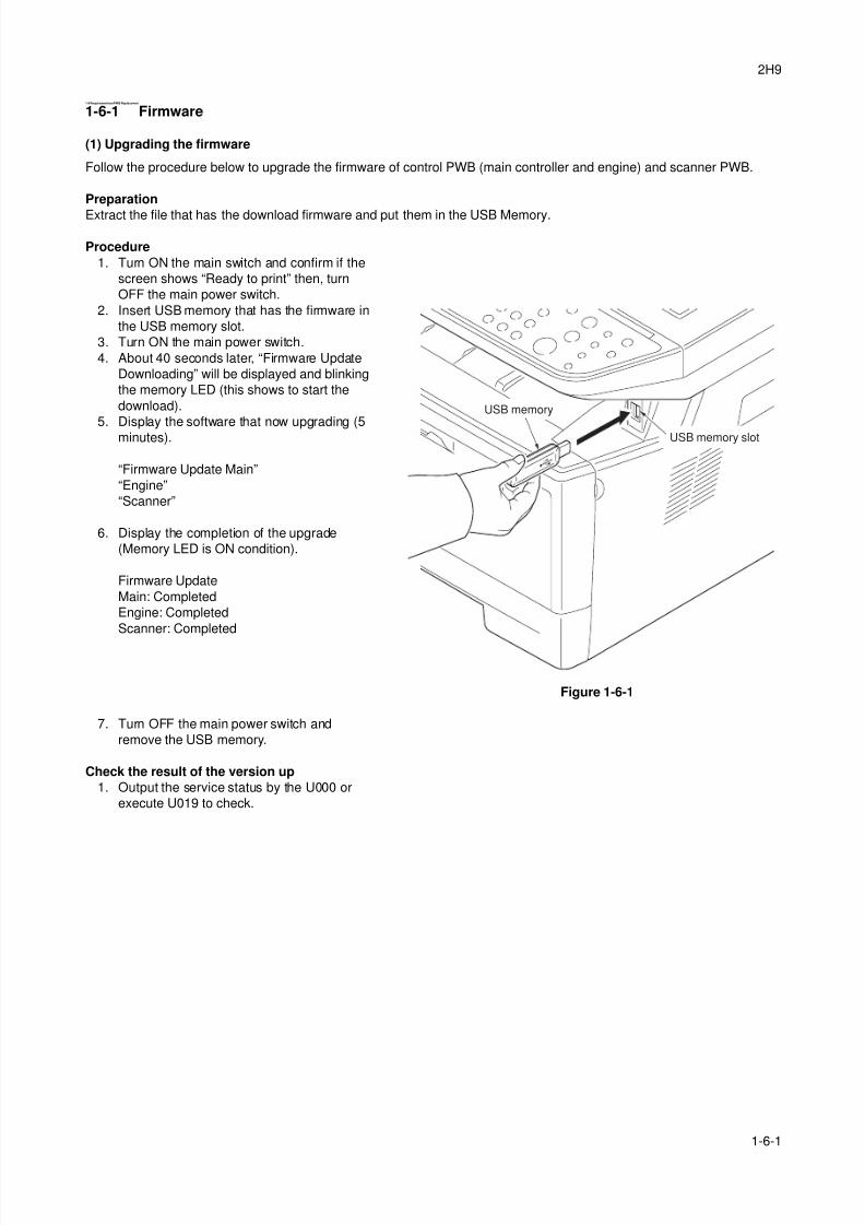
8/3/2019 Servi manualKM-2810ENSMR3
http://slidepdf.com/reader/full/servi-manualkm-2810ensmr3 161/202
2H9
1-6-1
1-6 RequirementsonPWB Replacement
1-6-1 Firmware
(1) Upgrading the firmware
Follow the procedure below to upgrade the firmware of control PWB (main controller and engine) and scanner PWB.
Preparation
Extract the file that has the download firmware and put them in the USB Memory.
Procedure
1. Turn ON the main switch and confirm if the
screen shows “Ready to print” then, turn
OFF the main power switch.
2. Insert USB memory that has the firmware in
the USB memory slot.
3. Turn ON the main power switch.
4. About 40 seconds later, “Firmware Update
Downloading” will be displayed and blinking
the memory LED (this shows to start the
download).
5. Display the software that now upgrading (5
minutes).
“Firmware Update Main”
“Engine”
“Scanner”
6. Display the completion of the upgrade
(Memory LED is ON condition).
Firmware Update
Main: Completed
Engine: Completed
Scanner: Completed
Figure 1-6-1
7. Turn OFF the main power switch and
remove the USB memory.
Check the result of the version up
1. Output the service status by the U000 or
execute U019 to check.
USB memory
USB memory slot
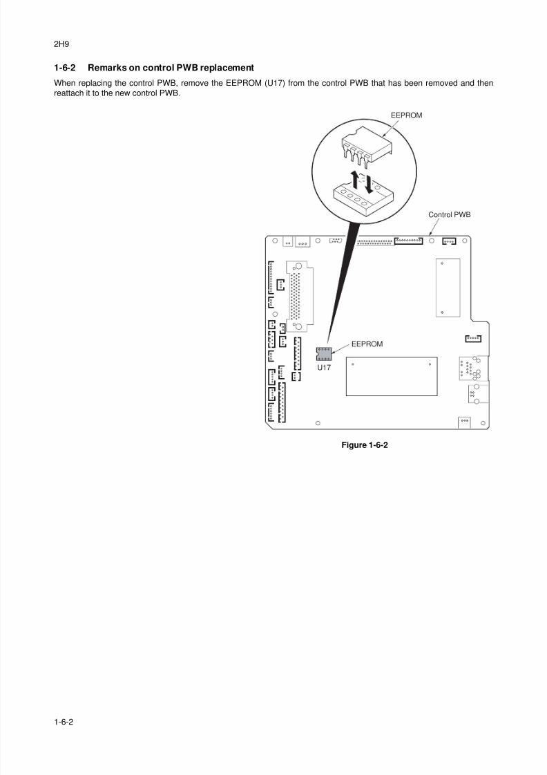
8/3/2019 Servi manualKM-2810ENSMR3
http://slidepdf.com/reader/full/servi-manualkm-2810ensmr3 162/202
2H9
1-6-2
1-6-2 Remarks on control PWB replacement
When replacing the control PWB, remove the EEPROM (U17) from the control PWB that has been removed and then
reattach it to the new control PWB.
Figure 1-6-2
EEPROM
U17
Control PWB
EEPROM
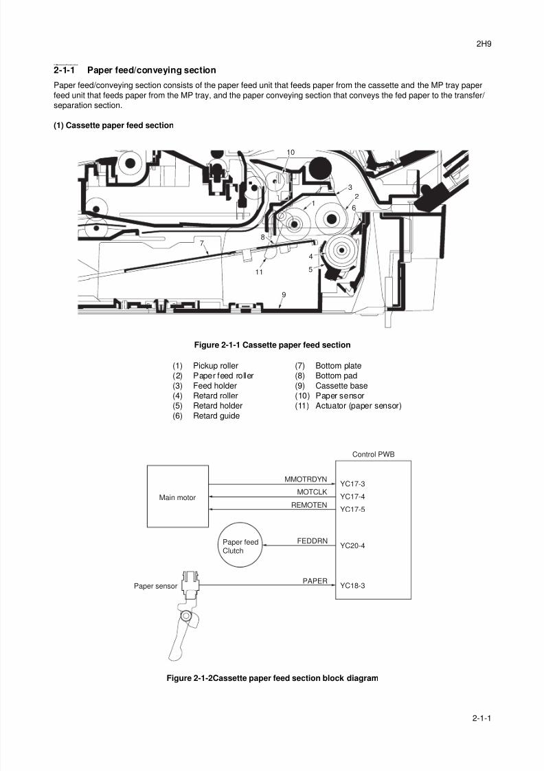
8/3/2019 Servi manualKM-2810ENSMR3
http://slidepdf.com/reader/full/servi-manualkm-2810ensmr3 163/202
2H9
2-1-1
2-1 Mechanical Construction
2-1-1 Paper feed/conveying section
Paper feed/conveying section consists of the paper feed unit that feeds paper from the cassette and the MP tray paper
feed unit that feeds paper from the MP tray, and the paper conveying section that conveys the fed paper to the transfer/
separation section.
(1) Cassette paper feed section
Figure 2-1-1 Cassette paper feed section
Figure 2-1-2Cassette paper feed section block diagram
1
9
7
3
4
5
2
6
8
10
11
(1) Pickup roller
(2) Paper feed roller
(3) Feed holder
(4) Retard roller
(5) Retard holder(6) Retard guide
(7) Bottom plate
(8) Bottom pad
(9) Cassette base
(10) Paper sensor
(11) Actuator (paper sensor)
FEDDRN
MMOTRDYN
YC18-3Paper sensor
Paper feedClutch
Main motor
Control PWB
PAPER
MOTCLK
REMOTEN
YC20-4
YC17-3
YC17-4
YC17-5

8/3/2019 Servi manualKM-2810ENSMR3
http://slidepdf.com/reader/full/servi-manualkm-2810ensmr3 164/202
2H9
2-1-2
(2) MP tray paper feed section
Figure 2-1-3 MP tray paper feed section
Figure 2-1-4 MP tray paper feed section block diagram
12
6
8
5
9
47
10
11
12
3
13
(1) MP paper feed roller
(2) MPF separation pad
(3) MPF separator
(4) MPF bottom plate
(5) MPF friction pad
(6) MP paper sensor
(7) Actuator (MP paper sensor)
(8) MPF frame
(9) MPF guide R/L
(10) MPF base
(11) MPF middle tray
(12) MPF upper tray
(13) MPF turn guide
MMOTRDYN
YC16-3
MPFDRN
MP paper sensor
MP paperfeed solenoid
Main motor
Control PWB
HANDSN
YC21-2
MOTCLK
REMOTEN
YC17-3
YC17-4
YC17-5
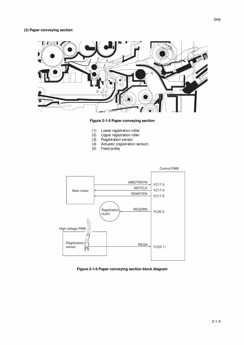
8/3/2019 Servi manualKM-2810ENSMR3
http://slidepdf.com/reader/full/servi-manualkm-2810ensmr3 165/202
2H9
2-1-3
(3) Paper conveying section
Figure 2-1-5 Paper conveying section
Figure 2-1-6 Paper conveying section block diagram
1
4
3
5
2
(1) Lower registration roller
(2) Upper registration roller
(3) Registration sensor
(4) Actuator (registration sensor)
(5) Feed pulley
MMOTRDYN
REGDRNRegistrationclutch
Main motor
Control PWB
YC23-11Registrationsensor
High voltage PWB
REGN
YC20-2
MOTCLK
REMOTEN
YC17-3
YC17-4
YC17-5
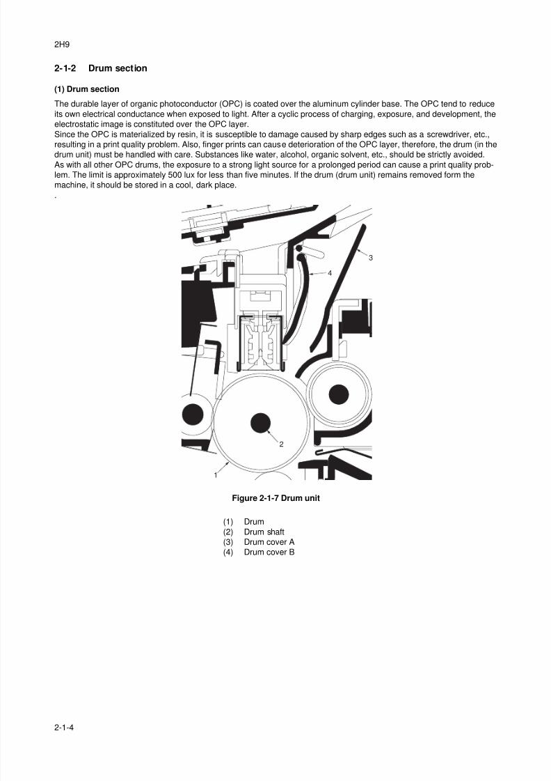
8/3/2019 Servi manualKM-2810ENSMR3
http://slidepdf.com/reader/full/servi-manualkm-2810ensmr3 166/202
2H9
2-1-4
2-1-2 Drum section
(1) Drum section
The durable layer of organic photoconductor (OPC) is coated over the aluminum cylinder base. The OPC tend to reduce
its own electrical conductance when exposed to light. After a cyclic process of charging, exposure, and development, the
electrostatic image is constituted over the OPC layer.
Since the OPC is materialized by resin, it is susceptible to damage caused by sharp edges such as a screwdriver, etc.,resulting in a print quality problem. Also, finger prints can cause deterioration of the OPC layer, therefore, the drum (in the
drum unit) must be handled with care. Substances like water, alcohol, organic solvent, etc., should be strictly avoided.
As with all other OPC drums, the exposure to a strong light source for a prolonged period can cause a print quality prob-
lem. The limit is approximately 500 lux for less than five minutes. If the drum (drum unit) remains removed form the
machine, it should be stored in a cool, dark place.
.
Figure 2-1-7 Drum unit
1
2
3
4
(1) Drum
(2) Drum shaft
(3) Drum cover A
(4) Drum cover B
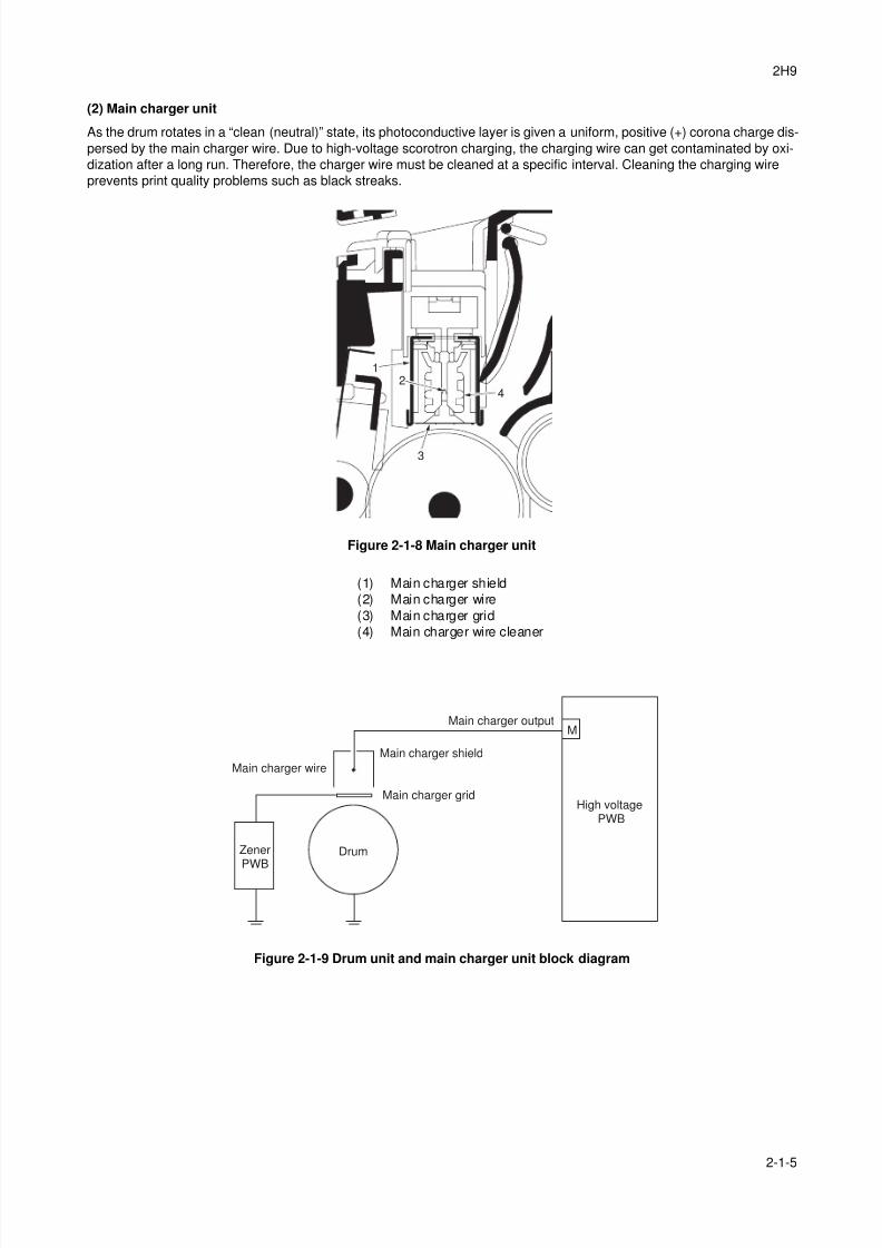
8/3/2019 Servi manualKM-2810ENSMR3
http://slidepdf.com/reader/full/servi-manualkm-2810ensmr3 167/202
2H9
2-1-5
(2) Main charger unit
As the drum rotates in a “clean (neutral)” state, its photoconductive layer is given a uniform, positive (+) corona charge dis-
persed by the main charger wire. Due to high-voltage scorotron charging, the charging wire can get contaminated by oxi-
dization after a long run. Therefore, the charger wire must be cleaned at a specific interval. Cleaning the charging wire
prevents print quality problems such as black streaks.
Figure 2-1-8 Main charger unit
Figure 2-1-9 Drum unit and main charger unit block diagram
1
42
3
(1) Main charger shield
(2) Main charger wire
(3) Main charger grid
(4) Main charger wire cleaner
Main charger wire
Main charger shield
Main charger grid
Drum
High voltagePWB
Main charger output
ZenerPWB
M
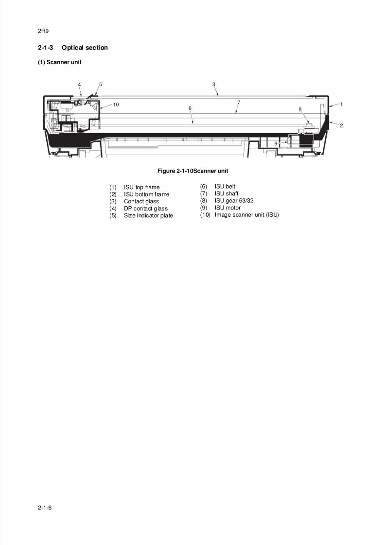
8/3/2019 Servi manualKM-2810ENSMR3
http://slidepdf.com/reader/full/servi-manualkm-2810ensmr3 168/202
2H9
2-1-6
2-1-3 Optical section
(1) Scanner unit
Figure 2-1-10Scanner unit
1
3
7
8
9
5
10
4
6
2
(1) ISU top frame
(2) ISU bottom frame
(3) Contact glass
(4) DP contact glass
(5) Size indicator plate
(6) ISU belt
(7) ISU shaft
(8) ISU gear 63/32
(9) ISU motor
(10) Image scanner unit (ISU)
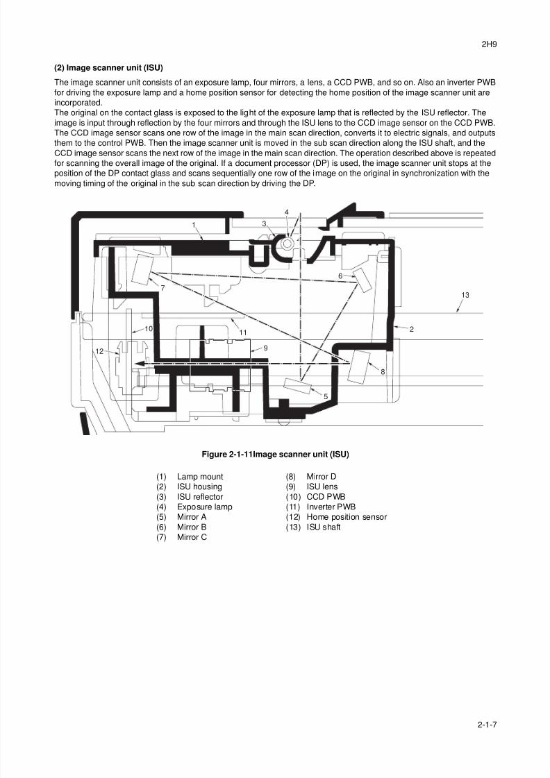
8/3/2019 Servi manualKM-2810ENSMR3
http://slidepdf.com/reader/full/servi-manualkm-2810ensmr3 169/202
2H9
2-1-7
(2) Image scanner unit (ISU)
The image scanner unit consists of an exposure lamp, four mirrors, a lens, a CCD PWB, and so on. Also an inverter PWB
for driving the exposure lamp and a home position sensor for detecting the home position of the image scanner unit are
incorporated.
The original on the contact glass is exposed to the light of the exposure lamp that is reflected by the ISU reflector. The
image is input through reflection by the four mirrors and through the ISU lens to the CCD image sensor on the CCD PWB.
The CCD image sensor scans one row of the image in the main scan direction, converts it to electric signals, and outputsthem to the control PWB. Then the image scanner unit is moved in the sub scan direction along the ISU shaft, and the
CCD image sensor scans the next row of the image in the main scan direction. The operation described above is repeated
for scanning the overall image of the original. If a document processor (DP) is used, the image scanner unit stops at the
position of the DP contact glass and scans sequentially one row of the image on the original in synchronization with the
moving timing of the original in the sub scan direction by driving the DP.
Figure 2-1-11Image scanner unit (ISU)
1 3
4
2
13
5
9
1011
12
6
7
8
(1) Lamp mount
(2) ISU housing
(3) ISU reflector
(4) Exposure lamp
(5) Mirror A
(6) Mirror B
(7) Mirror C
(8) Mirror D
(9) ISU lens
(10) CCD PWB
(11) Inverter PWB
(12) Home position sensor
(13) ISU shaft
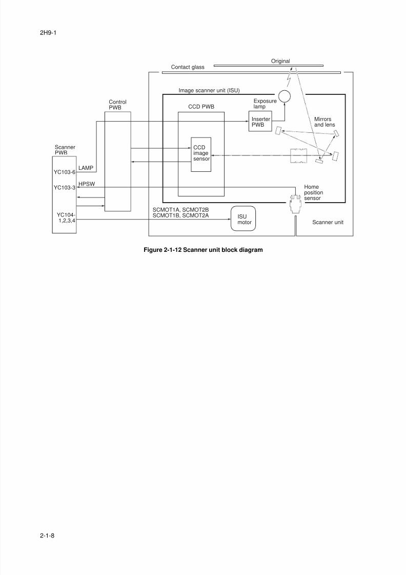
8/3/2019 Servi manualKM-2810ENSMR3
http://slidepdf.com/reader/full/servi-manualkm-2810ensmr3 170/202
2H9-1
2-1-8
Figure 2-1-12 Scanner unit block diagram
CCDimagesensor
ControlPWB
ScannerPWB
CCD PWB
HPSW
LAMP
SCMOT1A, SCMOT2BSCMOT1B, SCMOT2A
Exposurelamp
InserterPWB
ISUmotor
Homepositionsensor
Scanner unit
Mirrorsand lens
Image scanner unit (ISU)
OriginalContact glass
YC103-6
YC103-3
YC104-1,2,3,4
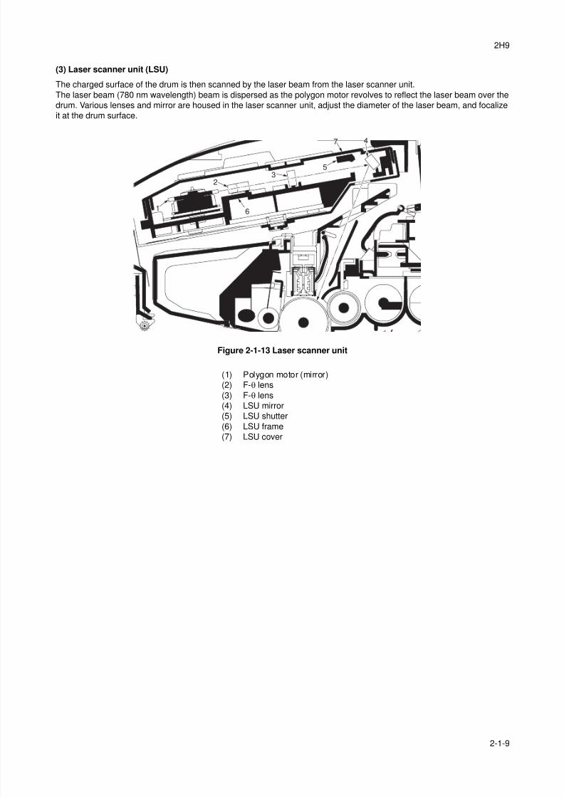
8/3/2019 Servi manualKM-2810ENSMR3
http://slidepdf.com/reader/full/servi-manualkm-2810ensmr3 171/202
2H9
2-1-9
(3) Laser scanner unit (LSU)
The charged surface of the drum is then scanned by the laser beam from the laser scanner unit.
The laser beam (780 nm wavelength) beam is dispersed as the polygon motor revolves to reflect the laser beam over the
drum. Various lenses and mirror are housed in the laser scanner unit, adjust the diameter of the laser beam, and focalize
it at the drum surface.
Figure 2-1-13 Laser scanner unit
1
23
4
5
7
6
(1) Polygon motor (mirror)
(2) F-θ lens
(3) F-θ lens
(4) LSU mirror
(5) LSU shutter(6) LSU frame
(7) LSU cover
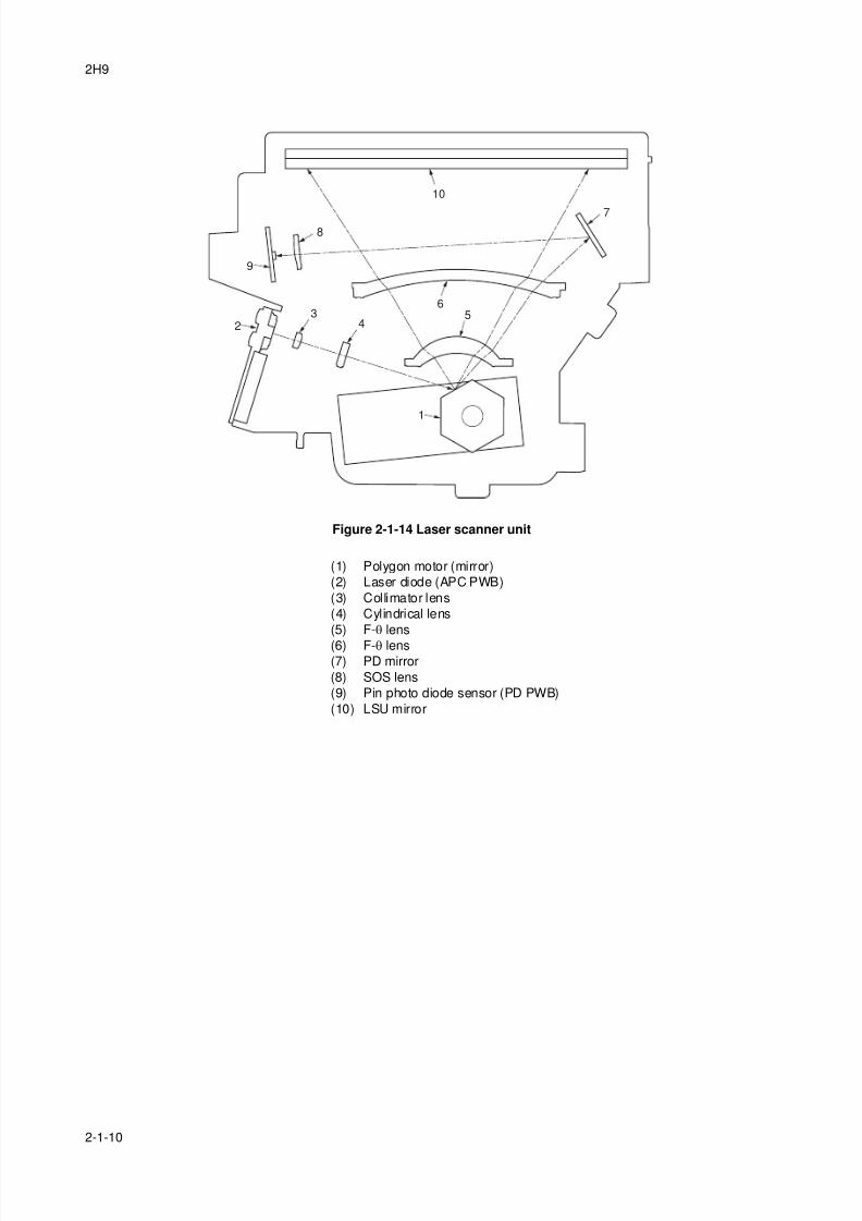
8/3/2019 Servi manualKM-2810ENSMR3
http://slidepdf.com/reader/full/servi-manualkm-2810ensmr3 172/202
2H9
2-1-10
Figure 2-1-14 Laser scanner unit
1
23
8
9
10
45
6
7
(1) Polygon motor (mirror)
(2) Laser diode (APC PWB)
(3) Collimator lens
(4) Cylindrical lens
(5) F-θ lens
(6) F-θ lens(7) PD mirror
(8) SOS lens
(9) Pin photo diode sensor (PD PWB)
(10) LSU mirror
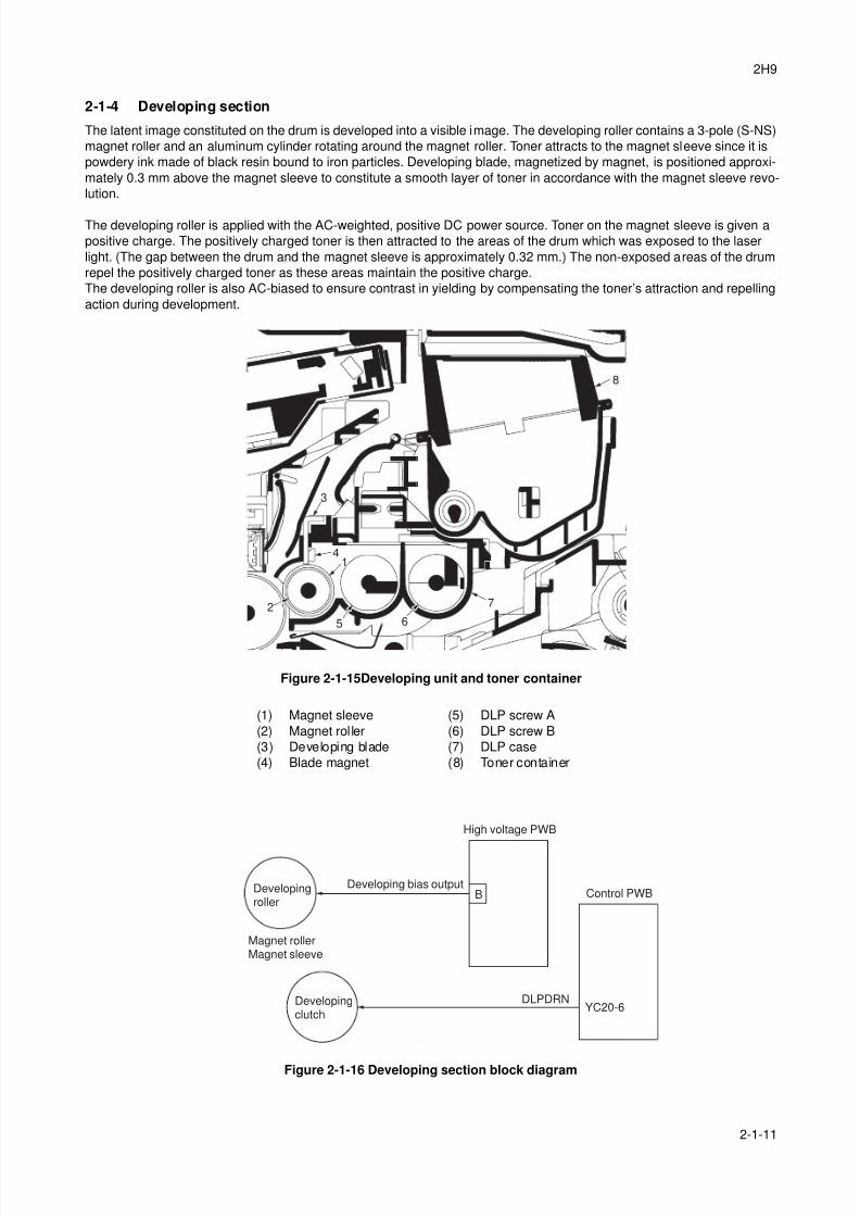
8/3/2019 Servi manualKM-2810ENSMR3
http://slidepdf.com/reader/full/servi-manualkm-2810ensmr3 173/202
2H9
2-1-11
2-1-4 Developing section
The latent image constituted on the drum is developed into a visible image. The developing roller contains a 3-pole (S-NS)
magnet roller and an aluminum cylinder rotating around the magnet roller. Toner attracts to the magnet sleeve since it is
powdery ink made of black resin bound to iron particles. Developing blade, magnetized by magnet, is positioned approxi-
mately 0.3 mm above the magnet sleeve to constitute a smooth layer of toner in accordance with the magnet sleeve revo-
lution.
The developing roller is applied with the AC-weighted, positive DC power source. Toner on the magnet sleeve is given a
positive charge. The positively charged toner is then attracted to the areas of the drum which was exposed to the laser
light. (The gap between the drum and the magnet sleeve is approximately 0.32 mm.) The non-exposed areas of the drum
repel the positively charged toner as these areas maintain the positive charge.
The developing roller is also AC-biased to ensure contrast in yielding by compensating the toner’s attraction and repelling
action during development.
Figure 2-1-15Developing unit and toner container
Figure 2-1-16 Developing section block diagram
1
3
4
6
7
8
5
2
(1) Magnet sleeve
(2) Magnet rol ler
(3) Developing blade
(4) Blade magnet
(5) DLP screw A
(6) DLP screw B
(7) DLP case
(8) Toner container
DLPDRNDevelopingclutch
YC20-6
BDevelopingroller
Magnet rollerMagnet sleeve
Developing bias output
High voltage PWB
Control PWB
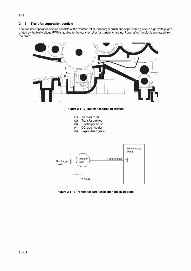
8/3/2019 Servi manualKM-2810ENSMR3
http://slidepdf.com/reader/full/servi-manualkm-2810ensmr3 174/202
2H9
2-1-12
2-1-5 Transfer/separation section
The transfer/separation section consists of the transfer roller, discharger brush and paper chute guide. A high voltage gen-
erated by the high voltage PWB is applied to the transfer roller for transfer charging. Paper after transfer is separated from
the drum.
Figure 2-1-17 Transfer/separation section
Figure 2-1-18 Transfer/separation section block diagram
1
2
3
4
5
(1) Transfer roller
(2) Transfer bushes
(3) Discharger brush
(4) DC brush holder
(5) Paper chute guide
TTransferroller
GND
High voltagePWB
Transfer biasDischargerbrush
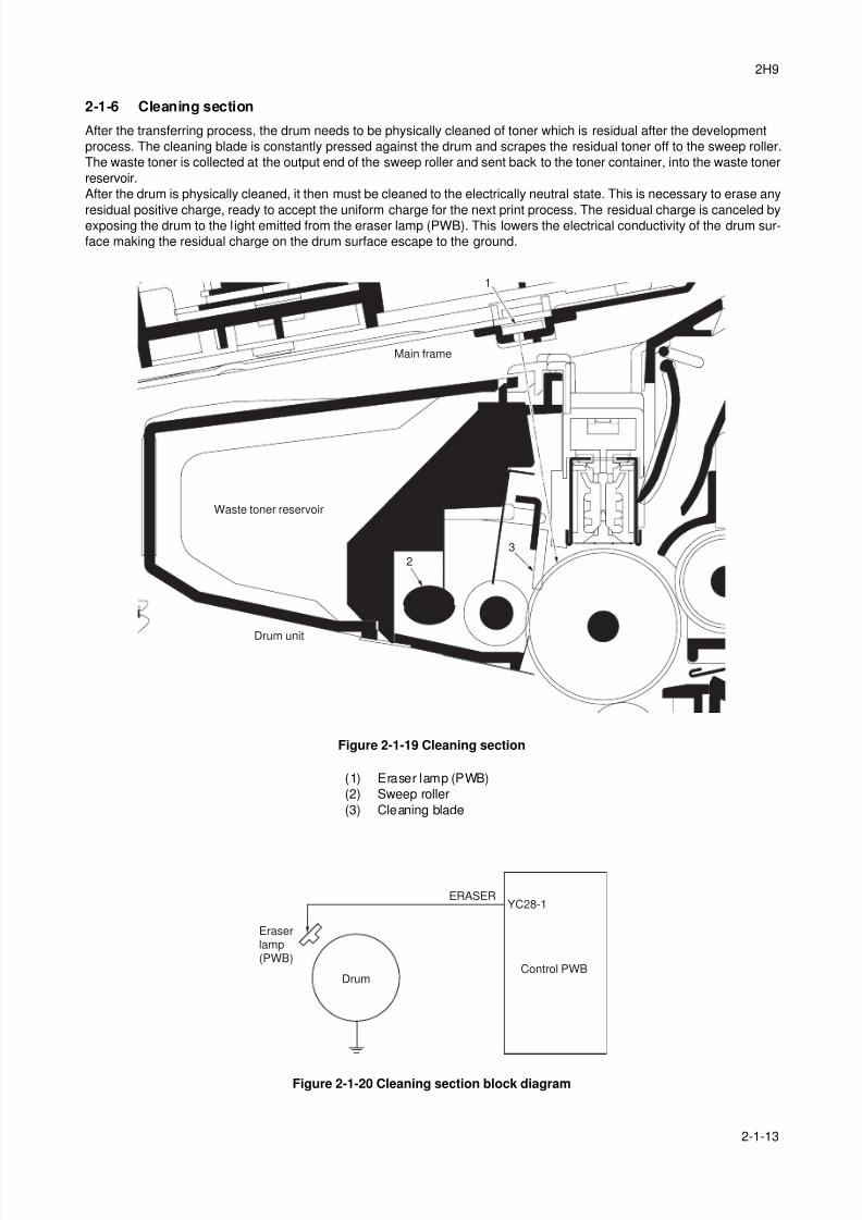
8/3/2019 Servi manualKM-2810ENSMR3
http://slidepdf.com/reader/full/servi-manualkm-2810ensmr3 175/202
2H9
2-1-13
2-1-6 Cleaning section
After the transferring process, the drum needs to be physically cleaned of toner which is residual after the development
process. The cleaning blade is constantly pressed against the drum and scrapes the residual toner off to the sweep roller.
The waste toner is collected at the output end of the sweep roller and sent back to the toner container, into the waste toner
reservoir.
After the drum is physically cleaned, it then must be cleaned to the electrically neutral state. This is necessary to erase any
residual positive charge, ready to accept the uniform charge for the next print process. The residual charge is canceled byexposing the drum to the l ight emitted from the eraser lamp (PWB). This lowers the electrical conductivity of the drum sur-
face making the residual charge on the drum surface escape to the ground.
Figure 2-1-19 Cleaning section
Figure 2-1-20 Cleaning section block diagram
1
3
2
Main frame
Waste toner reservoir
Drum unit
(1) Eraser lamp (PWB)
(2) Sweep roller
(3) Cleaning blade
ERASERYC28-1
Drum
Eraserlamp(PWB)
Control PWB
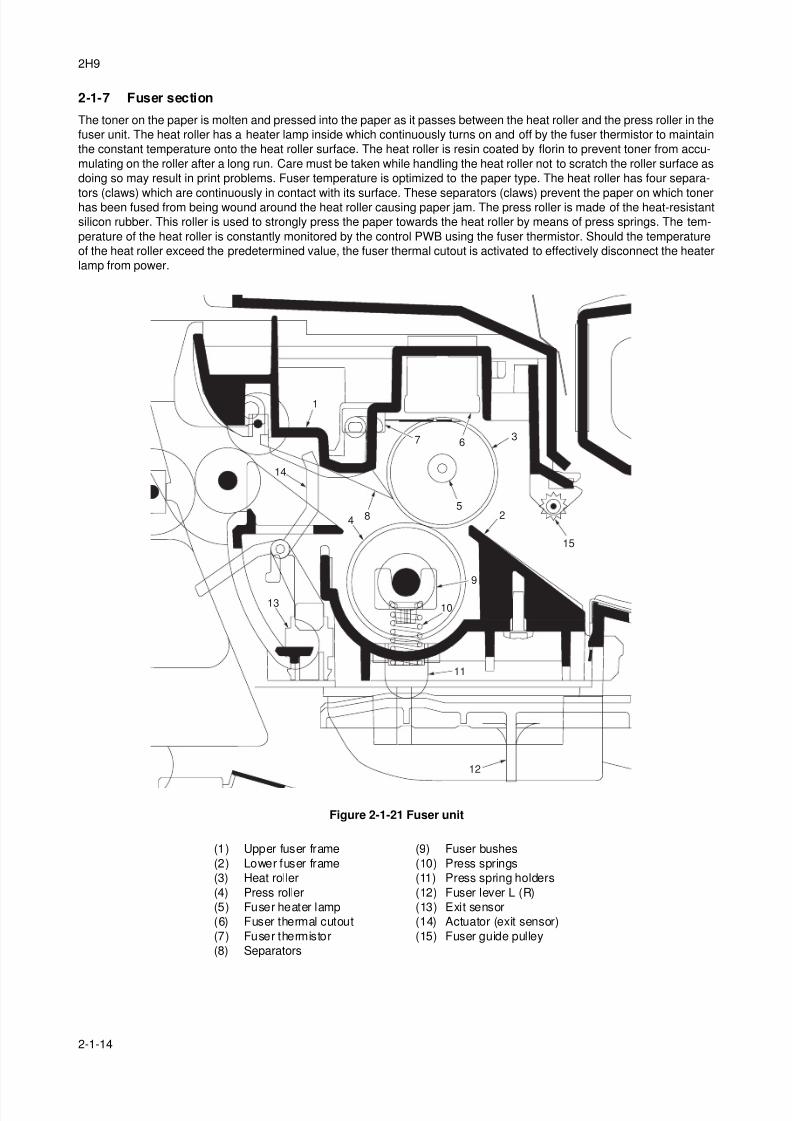
8/3/2019 Servi manualKM-2810ENSMR3
http://slidepdf.com/reader/full/servi-manualkm-2810ensmr3 176/202
2H9
2-1-14
2-1-7 Fuser section
The toner on the paper is molten and pressed into the paper as it passes between the heat roller and the press roller in the
fuser unit. The heat roller has a heater lamp inside which continuously turns on and off by the fuser thermistor to maintain
the constant temperature onto the heat roller surface. The heat roller is resin coated by florin to prevent toner from accu-
mulating on the roller after a long run. Care must be taken while handling the heat roller not to scratch the roller surface as
doing so may result in print problems. Fuser temperature is optimized to the paper type. The heat roller has four separa-
tors (claws) which are continuously in contact with its surface. These separators (claws) prevent the paper on which tonerhas been fused from being wound around the heat roller causing paper jam. The press roller is made of the heat-resistant
silicon rubber. This roller is used to strongly press the paper towards the heat roller by means of press springs. The tem-
perature of the heat roller is constantly monitored by the control PWB using the fuser thermistor. Should the temperature
of the heat roller exceed the predetermined value, the fuser thermal cutout is activated to effectively disconnect the heater
lamp from power.
Figure 2-1-21 Fuser unit
1
2
9
10
11
12
367
4
14
15
13
85
(1) Upper fuser frame
(2) Lower fuser frame
(3) Heat roller
(4) Press roller
(5) Fuser heater lamp
(6) Fuser thermal cutout
(7) Fuser thermistor
(8) Separators
(9) Fuser bushes
(10) Press springs
(11) Press spring holders
(12) Fuser lever L (R)
(13) Exit sensor
(14) Actuator (exit sensor)
(15) Fuser guide pulley
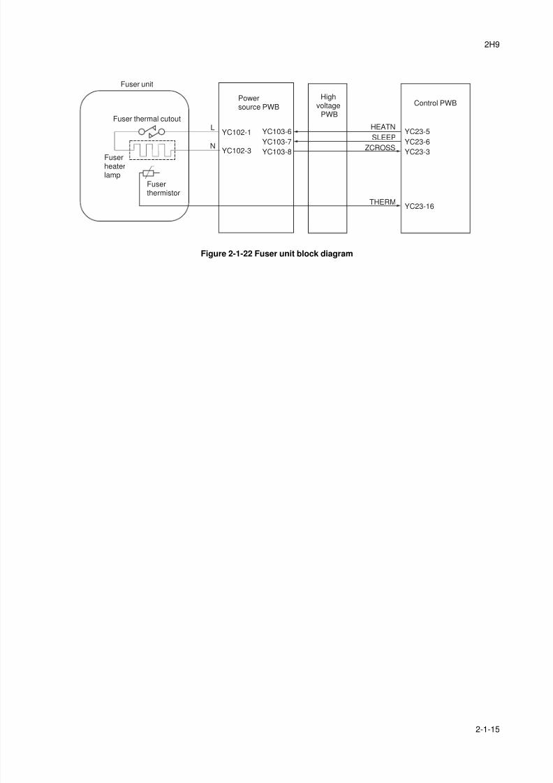
8/3/2019 Servi manualKM-2810ENSMR3
http://slidepdf.com/reader/full/servi-manualkm-2810ensmr3 177/202
2H9
2-1-15
Figure 2-1-22 Fuser unit block diagram
N
L
THERM
HEATN
SLEEPZCROSS
YC102-1
YC102-3
YC103-6
YC103-7
YC103-8
YC23-5
YC23-6
YC23-3
YC23-16
Fuser unit
Fuserthermistor
Fuserheaterlamp
Fuser thermal cutout
Powersource PWB
Control PWBHigh
voltagePWB
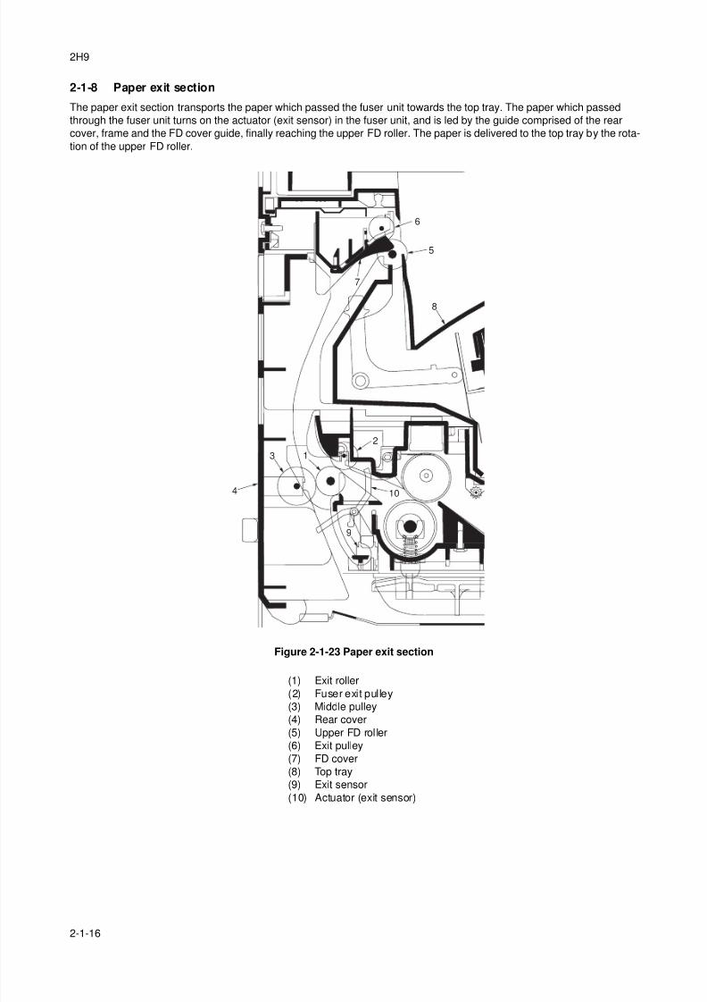
8/3/2019 Servi manualKM-2810ENSMR3
http://slidepdf.com/reader/full/servi-manualkm-2810ensmr3 178/202
2H9
2-1-16
2-1-8 Paper exit section
The paper exit section transports the paper which passed the fuser unit towards the top tray. The paper which passed
through the fuser unit turns on the actuator (exit sensor) in the fuser unit, and is led by the guide comprised of the rear
cover, frame and the FD cover guide, finally reaching the upper FD roller. The paper is delivered to the top tray by the rota-
tion of the upper FD roller.
Figure 2-1-23 Paper exit section
3
4 10
5
8
7
6
1
9
2
(1) Exit roller
(2) Fuser exit pulley
(3) Middle pulley(4) Rear cover
(5) Upper FD roller
(6) Exit pulley
(7) FD cover
(8) Top tray
(9) Exit sensor
(10) Actuator (exit sensor)
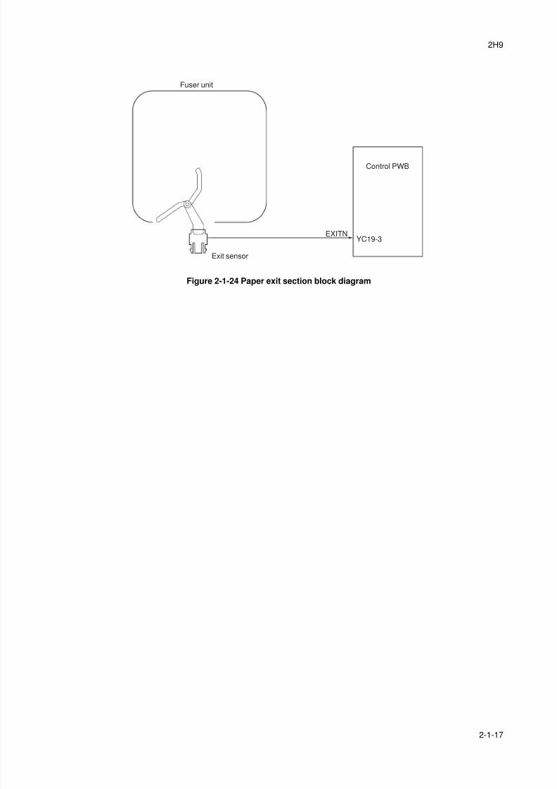
8/3/2019 Servi manualKM-2810ENSMR3
http://slidepdf.com/reader/full/servi-manualkm-2810ensmr3 179/202
2H9
2-1-17
Figure 2-1-24 Paper exit section block diagram
EXITNYC19-3
Fuser unit
Exit sensor
Control PWB
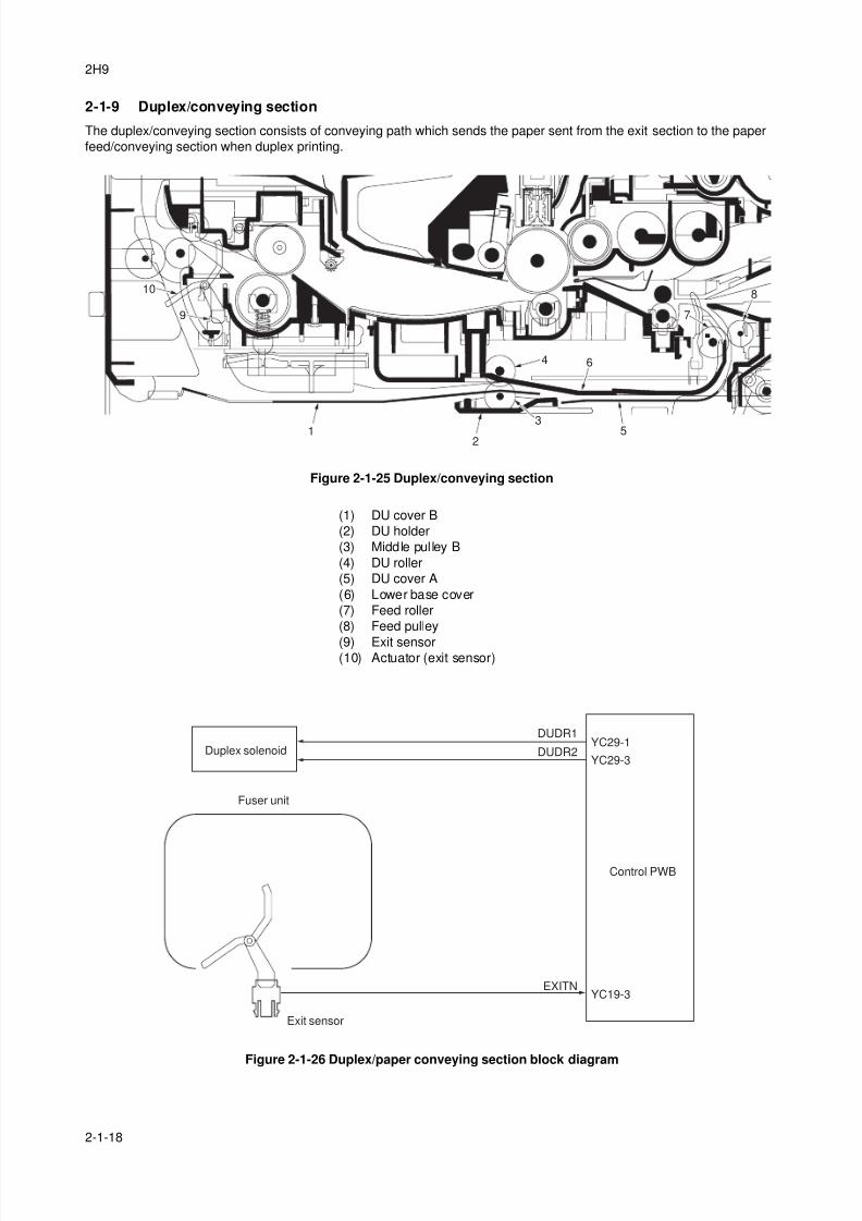
8/3/2019 Servi manualKM-2810ENSMR3
http://slidepdf.com/reader/full/servi-manualkm-2810ensmr3 180/202
2H9
2-1-18
2-1-9 Duplex/conveying section
The duplex/conveying section consists of conveying path which sends the paper sent from the exit section to the paper
feed/conveying section when duplex printing.
Figure 2-1-25 Duplex/conveying section
Figure 2-1-26 Duplex/paper conveying section block diagram
1
9
10
2
35
6
7
4
8
(1) DU cover B
(2) DU holder
(3) Middle pulley B
(4) DU roller
(5) DU cover A
(6) Lower base cover
(7) Feed roller
(8) Feed pulley
(9) Exit sensor(10) Actuator (exit sensor)
EXITN
DUDR1
DUDR2
YC19-3
YC29-1
YC29-3
Fuser unit
Exit sensor
Duplex solenoid
Control PWB
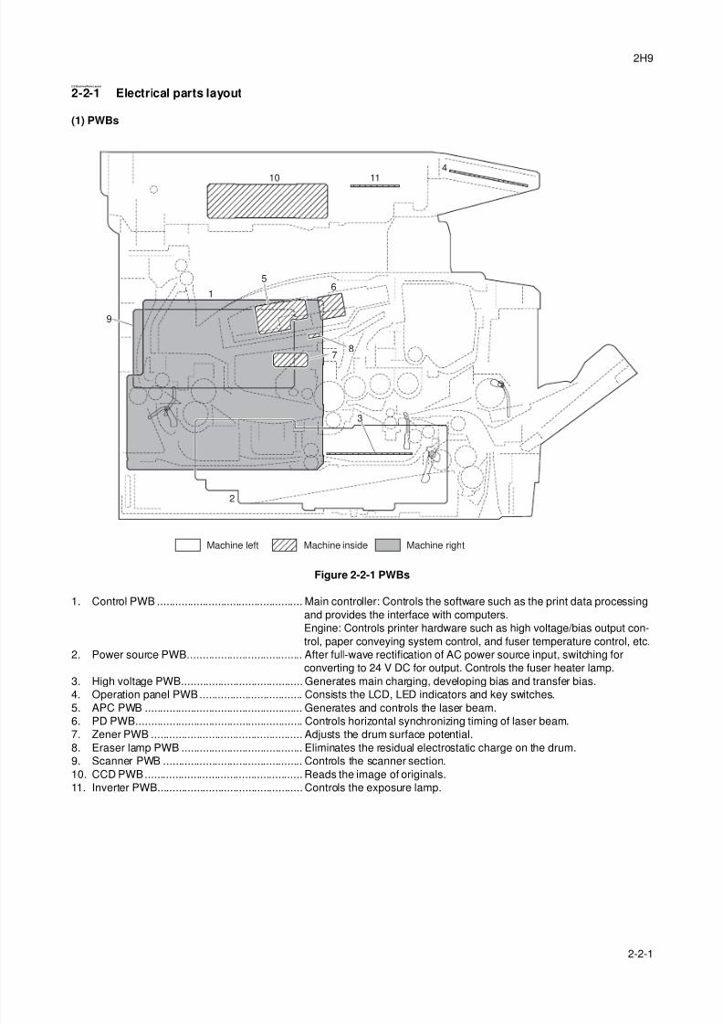
8/3/2019 Servi manualKM-2810ENSMR3
http://slidepdf.com/reader/full/servi-manualkm-2810ensmr3 181/202
2H9
2-2-1
2-2 ElectricalParts Layout
2-2-1 Electrical parts layout
(1) PWBs
Figure 2-2-1 PWBs
1. Control PWB ................................................ Main controller: Controls the software such as the print data processing
and provides the interface with computers.
Engine: Controls printer hardware such as high voltage/bias output con-
trol, paper conveying system control, and fuser temperature control, etc.
2. Power source PWB...................................... After full-wave rectification of AC power source input, switching for
converting to 24 V DC for output. Controls the fuser heater lamp.
3. High voltage PWB........................................ Generates main charging, developing bias and transfer bias.
4. Operation panel PWB.................................. Consists the LCD, LED indicators and key switches.
5. APC PWB .................................................... Generates and controls the laser beam.
6. PD PWB....................................................... Controls horizontal synchronizing timing of laser beam.7. Zener PWB .................................................. Adjusts the drum surface potential.
8. Eraser lamp PWB ........................................ Eliminates the residual electrostatic charge on the drum.
9. Scanner PWB .............................................. Controls the scanner section.
10. CCD PWB.................................................... Reads the image of originals.
11. Inverter PWB................................................ Controls the exposure lamp.
Machine insideMachine left Machine right
1
2
4
5
7
8
6
9
10 11
3
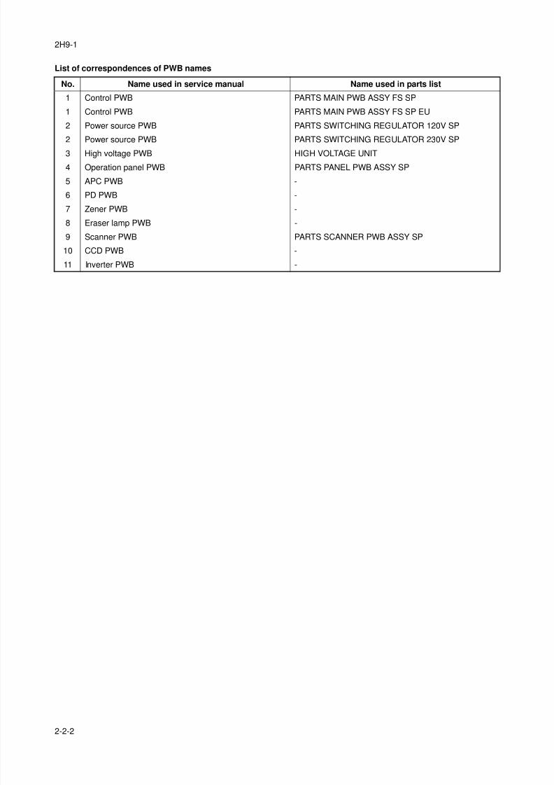
8/3/2019 Servi manualKM-2810ENSMR3
http://slidepdf.com/reader/full/servi-manualkm-2810ensmr3 182/202
2H9-1
2-2-2
List of correspondences of PWB names
No. Name used in service manual Name used in parts list
1 Control PWB PARTS MAIN PWB ASSY FS SP
1 Control PWB PARTS MAIN PWB ASSY FS SP EU
2 Power source PWB PARTS SWITCHING REGULATOR 120V SP
2 Power source PWB PARTS SWITCHING REGULATOR 230V SP
3 High voltage PWB HIGH VOLTAGE UNIT
4 Operation panel PWB PARTS PANEL PWB ASSY SP
5 APC PWB -
6 PD PWB -
7 Zener PWB -
8 Eraser lamp PWB -
9 Scanner PWB PARTS SCANNER PWB ASSY SP
10 CCD PWB -
11 Inverter PWB -
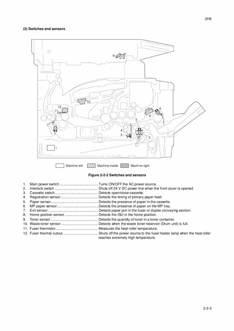
8/3/2019 Servi manualKM-2810ENSMR3
http://slidepdf.com/reader/full/servi-manualkm-2810ensmr3 183/202
2H9
2-2-3
(2) Switches and sensors
Figure 2-2-2 Switches and sensors
1. Main power switch ....................................... Turns ON/OFF the AC power source.
2. Interlock switch ............................................ Shuts off 24 V DC power line when the front cover is opened.
3. Cassette switch............................................ Detects open/close cassette.
4. Registration sensor...................................... Detects the timing of primary paper feed.
5. Paper sensor................................................ Detects the presence of paper in the cassette.
6. MP paper sensor.......................................... Detects the presence of paper on the MP tray.
7. Exit sensor ................................................... Detects paper jam in the fuser or duplex conveying section.
8. Home position sensor .................................. Detects the ISU in the home position.
9. Toner sensor ................................................ Detects the quantity of toner in a toner container.
10. Waste toner sensor...................................... Detects when the waste toner reservoir (Drum unit) is full.
11. Fuser thermistor........................................... Measures the heat roller temperature.
12. Fuser thermal cutout.................................... Shuts off the power source to the fuser heater lamp when the heat rollerreaches extremely high temperature.
1
2
6
8
3
4
5
7
9
12
10
11
Machine insideMachine left Machine right
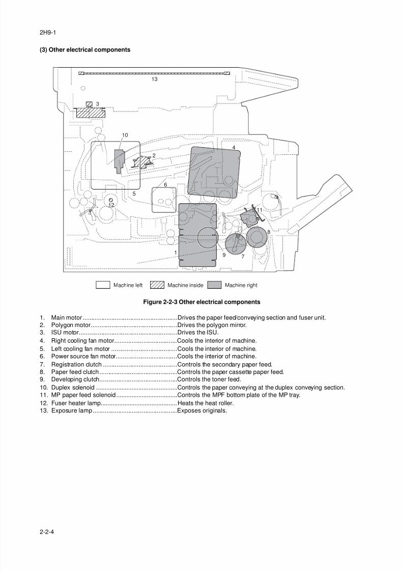
8/3/2019 Servi manualKM-2810ENSMR3
http://slidepdf.com/reader/full/servi-manualkm-2810ensmr3 184/202
2H9-1
2-2-4
(3) Other electrical components
Figure 2-2-3 Other electrical components
1. Main motor ........................................................Drives the paper feed/conveying section and fuser unit.
2. Polygon motor...................................................Drives the polygon mirror.
3. ISU motor..........................................................Drives the ISU.
4. Right cooling fan motor.....................................Cools the interior of machine.
5. Left cooling fan motor .......................................Cools the interior of machine.
6. Power source fan motor....................................Cools the interior of machine.
7. Registration clutch ............................................Controls the secondary paper feed.
8. Paper feed clutch..............................................Controls the paper cassette paper feed.
9. Developing clutch..............................................Controls the toner feed.
10. Duplex solenoid ................................................Controls the paper conveying at the duplex conveying section.
11. MP paper feed solenoid ....................................Controls the MPF bottom plate of the MP tray.
12. Fuser heater lamp.............................................Heats the heat roller.
13. Exposure lamp..................................................Exposes originals.
1
2
4
5
6
79
12
10
13
8
11
Machine insideMachine left Machine right
3
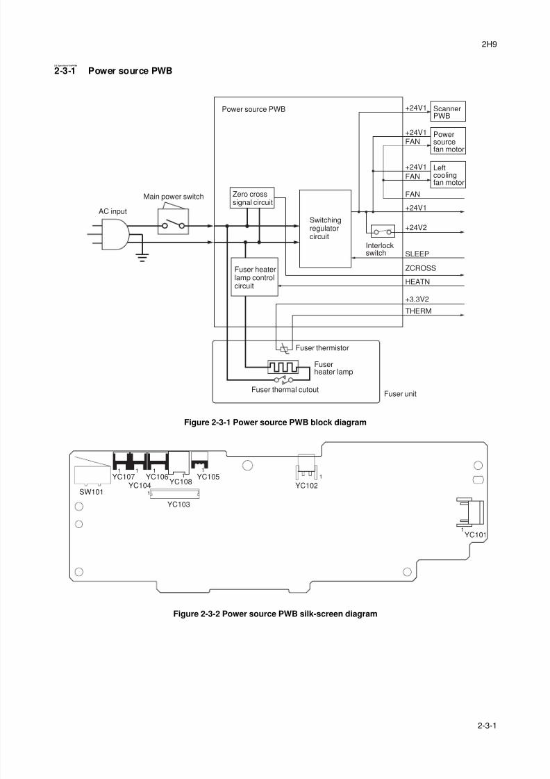
8/3/2019 Servi manualKM-2810ENSMR3
http://slidepdf.com/reader/full/servi-manualkm-2810ensmr3 185/202
2H9
2-3-1
2-3 Operationof thePWBs
2-3-1 Power source PWB
Figure 2-3-1 Power source PWB block diagram
Figure 2-3-2 Power source PWB silk-screen diagram
SLEEP
+24V2
+24V1
+24V1
+24V1
+24V1
FAN
FAN
FAN
+3.3V2
ZCROSS
HEATN
THERM
Leftcoolingfan motor
Powersourcefan motor
ScannerPWB
Power source PWB
Fuser thermistor
Fuser thermal cutoutFuser unit
Switchingregulatorcircuit
Zero crosssignal circuit
AC input
Interlockswitch
Main power switch
Fuser heaterlamp controlcircuit
Fuserheater lamp
YC107
SW101
1 1 11
1
11
1
YC104YC106
YC108
YC103
YC105YC102
YC101
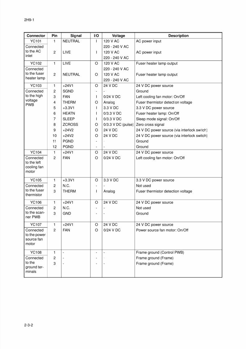
8/3/2019 Servi manualKM-2810ENSMR3
http://slidepdf.com/reader/full/servi-manualkm-2810ensmr3 186/202
2H9-1
2-3-2
Connector Pin Signal I/O Voltage Description
YC101 1 NEUTRAL I 120 V AC AC power input
Connected
to the AC
inlet
220 - 240 V AC
2 LIVE I 120 V AC AC power input
220 - 240 V AC
YC102 1 LIVE O 120 V AC Fuser heater lamp output
Connected
to the fuser
heater lamp
220 - 240 V AC
2 NEUTRAL O 120 V AC Fuser heater lamp output
220 - 240 V AC
YC103 1 +24V1 O 24 V DC 24 V DC power source
Connected
to the high
voltage
PWB
2 SGND - - Ground
3 FAN I 0/24 V DC Left cooling fan motor: On/Off
4 THERM O Analog Fuser thermistor detection voltage
5 +3.3V1 I 3.3 V DC 3.3 V DC power source
6 HEATN I 0/3.3 V DC Fuser heater lamp: On/Off
7 SLEEP I 0/3.3 V DC Sleep mode signal: On/Off
8 ZCROSS O 0/3.3 V DC (pulse) Zero cross signal
9 +24V2 O 24 V DC 24 V DC power source (via interlock switch)
10 +24V2 O 24 V DC 24 V DC power source (via interlock switch)
11 PGND - - Ground
12 PGND - - Ground
YC104 1 +24V1 O 24 V DC 24 V DC power source
Connected
to the left
cooling fan
motor
2 FAN O 0/24 V DC Left cooling fan motor: On/Off
YC105 1 +3.3V1 O 3.3 V DC 3.3 V DC power source
Connected
to the fuser
thermistor
2 N.C. - - Not used
3 THERM I Analog Fuser thermistor detection voltage
YC106 1 +24V1 O 24 V DC 24 V DC power source
Connected
to the scan-
ner PWB
2 N.C. - - Not used
3 GND - - Ground
YC107 1 +24V1 O 24 V DC 24 V DC power source
Connected
to the power
source fan
motor
2 FAN O 0/24 V DC Power source fan motor: On/Off
YC108 1 - - - Frame ground (Control PWB)
Connected
to the
ground ter-
minals
2 - - - Frame ground (Frame)
3 - - - Frame ground (Frame)
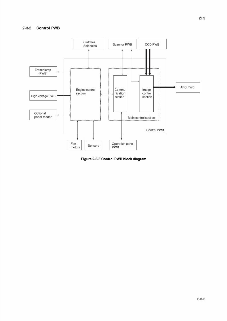
8/3/2019 Servi manualKM-2810ENSMR3
http://slidepdf.com/reader/full/servi-manualkm-2810ensmr3 187/202
2H9
2-3-3
2-3-2 Control PWB
Figure 2-3-3 Control PWB block diagram
ClutchesSolenoids Scanner PWB CCD PWB
APC PWB
Operation panelPWB
SensorsFanmotors
Optionalpaper feeder
Engine controlsection
Main control section
Commu-nicationsection
Imagecontrolsection
Control PWB
High voltage PWB
Eraser lamp(PWB)
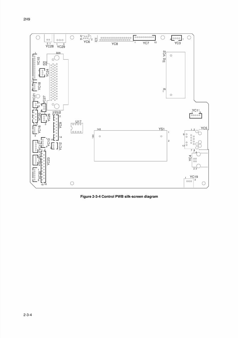
8/3/2019 Servi manualKM-2810ENSMR3
http://slidepdf.com/reader/full/servi-manualkm-2810ensmr3 188/202
2H9
2-3-4
Figure 2-3-4 Control PWB silk-screen diagram
2 1 1YC29YC28
3
5
6
YC6YC8
2 3132
1 10
4 1
YC7 YC3
Y C 2
5025
261
1
YC11
YC5
1
1
91
2
YS1143
U17
1 4 4
12
2
7
Y C 4
841
32
1 YC193
5
19
Y C 3 0
Y C 2 3
Y C 2 5
Y C 1 7
Y C 1 3
Y C 1 6
Y C
2 0
Y C 2 7
A 1
A 2
B 1
B 2
Y C 2 1
Y C 1 8
Y C 2 4
Y C 1 0
A 2 9
B29
A 3 0
Y C
2 6
Y C 9
Y C 1 2
6
1
1
11
12
1
1
1
1
3
1
1
3
12
1
2
2
5 6
1
3
3
2
24
1415
4
51 2
18
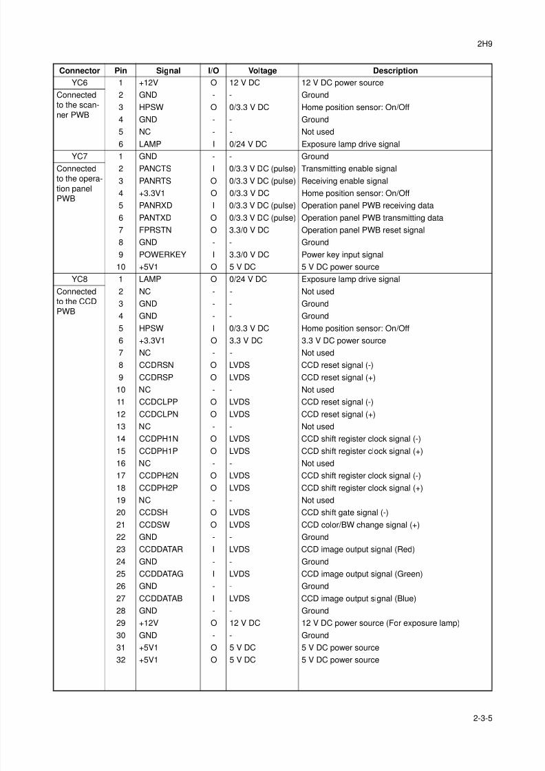
8/3/2019 Servi manualKM-2810ENSMR3
http://slidepdf.com/reader/full/servi-manualkm-2810ensmr3 189/202
2H9
2-3-5
Connector Pin Signal I/O Voltage Description
YC6 1 +12V O 12 V DC 12 V DC power source
Connected
to the scan-
ner PWB
2 GND - - Ground
3 HPSW O 0/3.3 V DC Home position sensor: On/Off
4 GND - - Ground
5 NC - - Not used6 LAMP I 0/24 V DC Exposure lamp drive signal
YC7 1 GND - - Ground
Connected
to the opera-
tion panel
PWB
2 PANCTS I 0/3.3 V DC (pulse) Transmitting enable signal
3 PANRTS O 0/3.3 V DC (pulse) Receiving enable signal
4 +3.3V1 O 0/3.3 V DC Home position sensor: On/Off
5 PANRXD I 0/3.3 V DC (pulse) Operation panel PWB receiving data
6 PANTXD O 0/3.3 V DC (pulse) Operation panel PWB transmitting data
7 FPRSTN O 3.3/0 V DC Operation panel PWB reset signal
8 GND - - Ground
9 POWERKEY I 3.3/0 V DC Power key input signal
10 +5V1 O 5 V DC 5 V DC power sourceYC8 1 LAMP O 0/24 V DC Exposure lamp drive signal
Connected
to the CCD
PWB
2 NC - - Not used
3 GND - - Ground
4 GND - - Ground
5 HPSW I 0/3.3 V DC Home position sensor: On/Off
6 +3.3V1 O 3.3 V DC 3.3 V DC power source
7 NC - - Not used
8 CCDRSN O LVDS CCD reset signal (-)
9 CCDRSP O LVDS CCD reset signal (+)
10 NC - - Not used
11 CCDCLPP O LVDS CCD reset signal (-)12 CCDCLPN O LVDS CCD reset signal (+)
13 NC - - Not used
14 CCDPH1N O LVDS CCD shift register clock signal (-)
15 CCDPH1P O LVDS CCD shift register clock signal (+)
16 NC - - Not used
17 CCDPH2N O LVDS CCD shift register clock signal (-)
18 CCDPH2P O LVDS CCD shift register clock signal (+)
19 NC - - Not used
20 CCDSH O LVDS CCD shift gate signal (-)
21 CCDSW O LVDS CCD color/BW change signal (+)
22 GND - - Ground23 CCDDATAR I LVDS CCD image output signal (Red)
24 GND - - Ground
25 CCDDATAG I LVDS CCD image output signal (Green)
26 GND - - Ground
27 CCDDATAB I LVDS CCD image output signal (Blue)
28 GND - - Ground
29 +12V O 12 V DC 12 V DC power source (For exposure lamp)
30 GND - - Ground
31 +5V1 O 5 V DC 5 V DC power source
32 +5V1 O 5 V DC 5 V DC power source
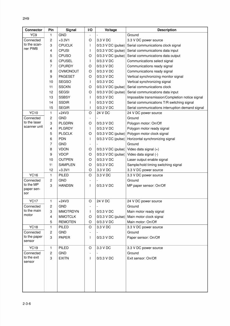
8/3/2019 Servi manualKM-2810ENSMR3
http://slidepdf.com/reader/full/servi-manualkm-2810ensmr3 190/202
2H9
2-3-6
YC9 1 GND - - Ground
Connected
to the scan-
ner PWB
2 +3.3V1 O 3.3 V DC 3.3 V DC power source
3 CPUCLK I 0/3.3 V DC (pulse) Serial communications clock signal
4 CPUSI I 0/3.3 V DC (pulse) Serial communications data input
5 CPUSO O 0/3.3 V DC (pulse) Serial communications data output6 CPUSEL I 0/3.3 V DC Communications select signal
7 CPURDY O 0/3.3 V DC Communications ready signal
8 OVMONOUT O 0/3.3 V DC Communications ready signal
9 PAGESET O 0/3.3 V DC Vertical synchronizing monitor signal
10 SEGSO I 0/3.3 V DC Vertical synchronizing signal
11 SSCKN O 0/3.3 V DC (pulse) Serial communications clock
12 SEGSI O 0/3.3 V DC (pulse) Serial communications data input
13 SSBSY I 0/3.3 V DC Impossible transmission/Completion notice signal
14 SSDIR I 0/3.3 V DC Serial communications T/R switching signal
15 SEGIR I 0/3.3 V DC Serial communications interruption demand signal
YC10 1 +24V3 O 24 V DC 24 V DC power sourceConnected
to the laser
scanner unit
2 GND - - Ground
3 PLGDRN O 0/3.3 V DC Polygon motor: On/Off
4 PLGRDY I 0/3.3 V DC Polygon motor ready signal
5 PLGCLK O 0/3.3 V DC (pulse) Polygon motor clock signal
6 PDN I 0/3.3 V DC (pulse) Horizontal synchronizing signal
7 GND - - Ground
8 VDON O 0/3.3 V DC (pulse) Video data signal (+)
9 VDOP O 0/3.3 V DC (pulse) Video data signal (-)
10 OUTPEN O 0/3.3 V DC Laser output enable signal
11 SAMPLEN O 0/3.3 V DC Sample/hold timing switching signal
12 +3.3V1 O 3.3 V DC 3.3 V DC power sourceYC16 1 PILED O 3.3 V DC 3.3 V DC power source
Connected
to the MP
paper sen-
sor
2 GND - - Ground
3 HANDSN I 0/3.3 V DC MP paper sensor: On/Off
YC17 1 +24V3 O 24 V DC 24 V DC power source
Connected
to the main
motor
2 GND - - Ground
3 MMOTRDYN I 0/3.3 V DC Main motor ready signal
4 MMOTCLK O 0/3.3 V DC (pulse) Main motor clock signal
5 REMOTEN O 0/3.3 V DC Main motor: On/Off
YC18 1 PILED O 3.3 V DC 3.3 V DC power sourceConnected
to the paper
sensor
2 GND - - Ground
3 PAPER I 0/3.3 V DC Paper sensor: On/Off
YC19 1 PILED O 3.3 V DC 3.3 V DC power source
Connected
to the exit
sensor
2 GND - - Ground
3 EXITN I 0/3.3 V DC Exit sensor: On/Off
Connector Pin Signal I/O Voltage Description
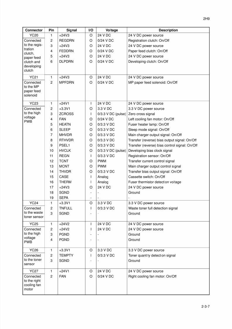
8/3/2019 Servi manualKM-2810ENSMR3
http://slidepdf.com/reader/full/servi-manualkm-2810ensmr3 191/202
2H9
2-3-7
YC20 1 +24V3 O 24 V DC 24 V DC power source
Connected
to the regis-
tration
clutch,
paper feedclutch and
developing
clutch
2 REGDRN O 0/24 V DC Registration clutch: On/Off
3 +24V3 O 24 V DC 24 V DC power source
4 FEDDRN O 0/24 V DC Paper feed clutch: On/Off
5 +24V3 O 24 V DC 24 V DC power source6 DLPDRN O 0/24 V DC Developing clutch: On/Off
YC21 1 +24V3 O 24 V DC 24 V DC power source
Connected
to the MP
paper feed
solenoid
2 MPFDRN O 0/24 V DC MP paper feed solenoid: On/Off
YC23 1 +24V1 I 24 V DC 24 V DC power source
Connected
to the high
voltage
PWB
2 +3.3V1 O 3.3 V DC 3.3 V DC power source
3 ZCROSS I 0/3.3 V DC (pulse) Zero cross signal4 FAN O 0/24 V DC Left cooling fan motor: On/Off
5 HEATN O 0/3.3 V DC Fuser heater lamp: On/Off
6 SLEEP O 0/3.3 V DC Sleep mode signal: On/Off
7 MHVDR O 0/3.3 V DC Main charger output signal: On/Off
8 RTHVDR O 0/3.3 V DC Transfer (reverse) bias output signal: On/Off
9 PSEL1 O 0/3.3 V DC Transfer (reverse) bias control signal: On/Off
10 HVCLK O 0/3.3 V DC (pulse) Developing bias clock signal
11 REGN I 0/3.3 V DC Registration sensor: On/Off
12 TCNT O PWM Transfer current control signal
13 MCNT O PWM Main charger output control signal
14 THVDR O 0/3.3 V DC Transfer bias output signal: On/Off15 CASE I Analog Cassette switch: On/Off
16 THERM I Analog Fuser thermistor detection voltage
17 +24V3 O 24 V DC 24 V DC power source
18 SGND - - Ground
19 SEPA - - -
YC24 1 +3.3V1 O 3.3 V DC 3.3 V DC power source
Connected
to the waste
toner sensor
2 TNFULL I 0/3.3 V DC Waste toner full detection signal
3 SGND - - Ground
YC25 1 +24V2 I 24 V DC 24 V DC power source
Connectedto the high
voltage
PWB
2 +24V2 I 24 V DC 24 V DC power source3 PGND - - Ground
4 PGND - - Ground
YC26 1 +3.3V1 O 3.3 V DC 3.3 V DC power source
Connected
to the toner
sensor
2 TEMPTY I 0/3.3 V DC Toner quantity detection signal
3 SGND - - Ground
YC27 1 +24V1 O 24 V DC 24 V DC power source
Connected
to the right
cooling fan
motor
2 FAN O 0/24 V DC Right cooling fan motor: On/Off
Connector Pin Signal I/O Voltage Description
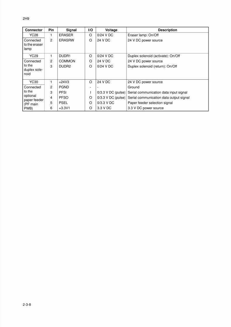
8/3/2019 Servi manualKM-2810ENSMR3
http://slidepdf.com/reader/full/servi-manualkm-2810ensmr3 192/202
2H9
2-3-8
YC28 1 ERASER O 0/24 V DC Eraser lamp: On/Off
Connected
to the eraser
lamp
2 ERASRW O 24 V DC 24 V DC power source
YC29 1 DUDR1 O 0/24 V DC Duplex solenoid (activate): On/OffConnected
to the
duplex sole-
noid
2 COMMON O 24 V DC 24 V DC power source
3 DUDR2 O 0/24 V DC Duplex solenoid (return): On/Off
YC30 1 +24V3 O 24 V DC 24 V DC power source
Connected
to the
optional
paper feeder
(PF main
PWB)
2 PGND - - Ground
3 PFSI I 0/3.3 V DC (pulse) Serial communication data input signal
4 PFSO O 0/3.3 V DC (pulse) Serial communication data output signal
5 PSEL O 0/3.3 V DC Paper feeder selection signal
6 +3.3V1 O 3.3 V DC 3.3 V DC power source
Connector Pin Signal I/O Voltage Description
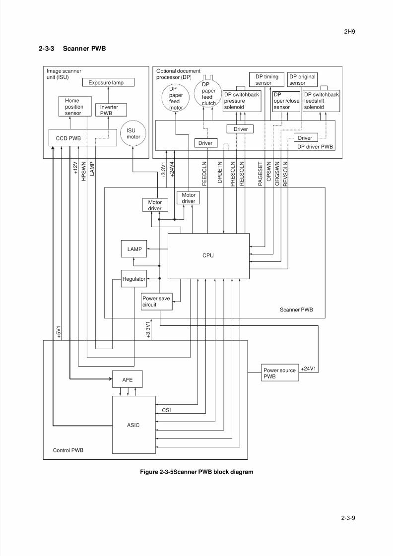
8/3/2019 Servi manualKM-2810ENSMR3
http://slidepdf.com/reader/full/servi-manualkm-2810ensmr3 193/202
2H9
2-3-9
2-3-3 Scanner PWB
Figure 2-3-5Scanner PWB block diagram
Image scannerunit (ISU)
Scanner PWB
Regulator
LAMPCPU
Control PWB
ASIC
AFE
Power savecircuit
Power sourcePWB
Optional documentprocessor (DP)
Exposure lamp
ISUmotorCCD PWB
Homepositionsensor
InverterPWB
Driver
Driver
Driver
MotordriverMotor
driver
F E E D C L N
D P D E T N
P R E S O L N
R E L S O L N
P A G E S E T
O P S W N
O R G S W N
R E V S O L N
+ 3
. 3 V 1
+ 2 4 V 4
L A M P
H P S W N
+ 1 2 V
CSI
+ 5 V 1
+ 3
. 3 V 1
+24V1
DP driver PWB
DP timingsensor
DP originalsensor
DPopen/closesensor
DP
paperfeedmotor
DPpaper
feedclutch
DP switchbackfeedshiftsolenoid
DP switchbackpressuresolenoid
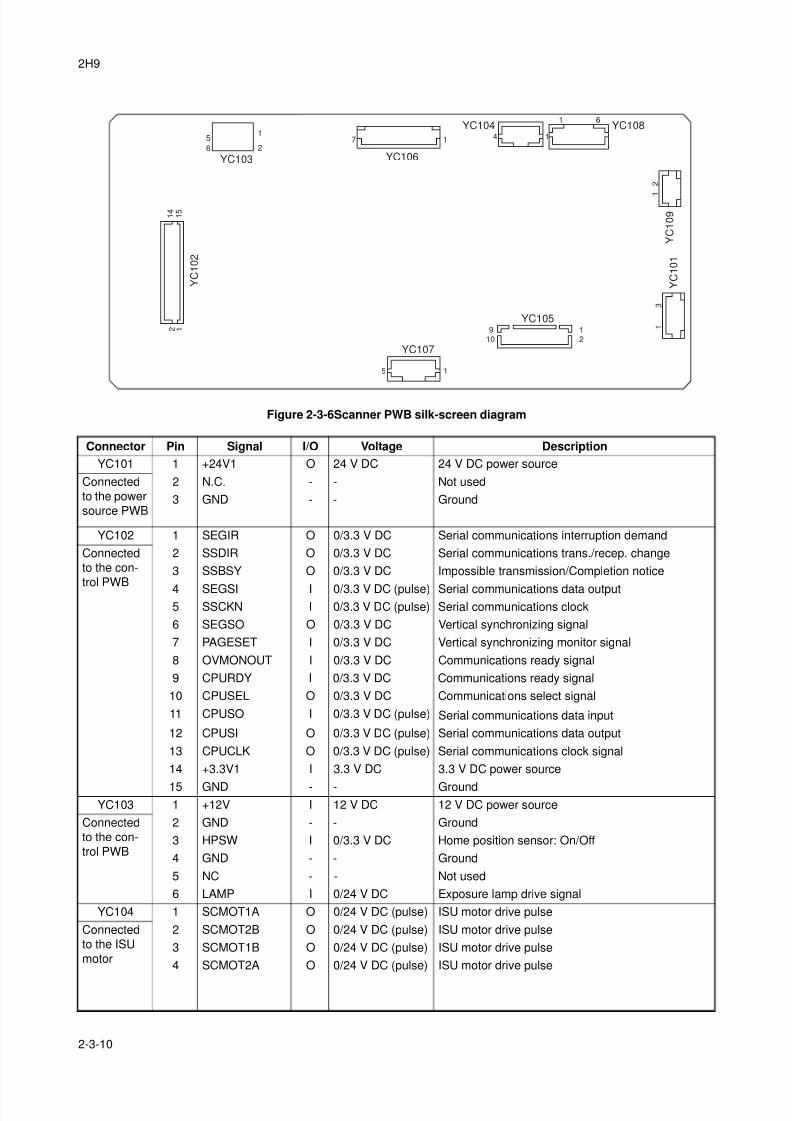
8/3/2019 Servi manualKM-2810ENSMR3
http://slidepdf.com/reader/full/servi-manualkm-2810ensmr3 194/202
2H9
2-3-10
Figure 2-3-6Scanner PWB silk-screen diagram
Connector Pin Signal I/O Voltage Description
YC101 1 +24V1 O 24 V DC 24 V DC power source
Connected
to the power
source PWB
2 N.C. - - Not used
3 GND - - Ground
YC102 1 SEGIR O 0/3.3 V DC Serial communications interruption demand
Connected
to the con-
trol PWB
2 SSDIR O 0/3.3 V DC Serial communications trans./recep. change
3 SSBSY O 0/3.3 V DC Impossible transmission/Completion notice
4 SEGSI I 0/3.3 V DC (pulse) Serial communications data output5 SSCKN I 0/3.3 V DC (pulse) Serial communications clock
6 SEGSO O 0/3.3 V DC Vertical synchronizing signal
7 PAGESET I 0/3.3 V DC Vertical synchronizing monitor signal
8 OVMONOUT I 0/3.3 V DC Communications ready signal
9 CPURDY I 0/3.3 V DC Communications ready signal
10 CPUSEL O 0/3.3 V DC Communications select signal
11 CPUSO I 0/3.3 V DC (pulse) Serial communications data input
12 CPUSI O 0/3.3 V DC (pulse) Serial communications data output
13 CPUCLK O 0/3.3 V DC (pulse) Serial communications clock signal
14 +3.3V1 I 3.3 V DC 3.3 V DC power source
15 GND - - GroundYC103 1 +12V I 12 V DC 12 V DC power source
Connected
to the con-
trol PWB
2 GND - - Ground
3 HPSW I 0/3.3 V DC Home position sensor: On/Off
4 GND - - Ground
5 NC - - Not used
6 LAMP I 0/24 V DC Exposure lamp drive signal
YC104 1 SCMOT1A O 0/24 V DC (pulse) ISU motor drive pulse
Connected
to the ISU
motor
2 SCMOT2B O 0/24 V DC (pulse) ISU motor drive pulse
3 SCMOT1B O 0/24 V DC (pulse) ISU motor drive pulse
4 SCMOT2A O 0/24 V DC (pulse) ISU motor drive pulse
Y C 1 0 1
Y C 1 0 9
YC108YC104
YC106
YC107
YC105
YC103
Y C 1 0 2
1
1
1
11
15
910
12
71
5
6
1 4
1 5
2 1
2
4
6
2
3

8/3/2019 Servi manualKM-2810ENSMR3
http://slidepdf.com/reader/full/servi-manualkm-2810ensmr3 195/202
2H9
2-3-11
YC105 1 +3.3V1 O 3.3 V DC 3.3 V DC power source
Connected
to the
optional DP
(DP driver
PWB)
2 GND - - Ground
3 TIMSWN I 0/3.3 V DC DP timing sensor: On/Off
4 ORGSWN I 0/3.3 V DC DP original sensor: On/Off
5 OPSWN I 0/3.3 V DC DP open/close sensor: On/Off6 DPDETN I 0/3.3 V DC DP installation detection signal
7 RELSOLN O 0/24 V DC DP switchback pressure solenoid: (Release) On/Off
8 PRESOLN O 0/24 V DC DP switchback pressure solenoid (Press.): On/Off
9 REVSOL O 0/24 V DC DP switchback feedshift solenoid: On/Off
10 FEEDCL O 0/24 V DC DP paper feed clutch: On/Off
YC108 1 MOT1A O 0/24 V DC (pulse) DP paper feed motor drive pulse
Connected
to the
optional DP
(DP driver
PWB)
2 MOT2B O 0/24 V DC (pulse) DP paper feed motor drive pulse
3 MOT1B O 0/24 V DC (pulse) DP paper feed motor drive pulse
4 MOT2A O 0/24 V DC (pulse) DP paper feed motor drive pulse
5 +24V4 O 24 V DC 24 V DC power source
6 GND - - GroundYC109 1 +24V4 O 24 V DC 24 V DC power source
Connected
to the
optional DP
(DP driver
PWB)
2 GND - - Ground
Connector Pin Signal I/O Voltage Description

8/3/2019 Servi manualKM-2810ENSMR3
http://slidepdf.com/reader/full/servi-manualkm-2810ensmr3 196/202
2H9
2-3-12
This page is intentionally left blank.
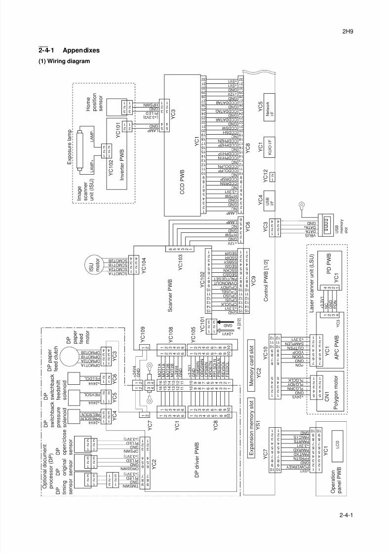
8/3/2019 Servi manualKM-2810ENSMR3
http://slidepdf.com/reader/full/servi-manualkm-2810ensmr3 197/202
2H9
2-4-1
2-4 Appendixes
2-4-1 Appendixes
(1) Wiring diagram
K U I O I / F
+ 2 4 V 3 G N D P L G D R N
P L G R D Y P L G C L K
P D N G N D V D O N V D O P O U T P E N S A M P L E N + 3 . 3 V 1
U S B
I / F
N e
t w o r k
I / F
+ 5 V 1 P O W E R K E Y G N D F P R S T N P A N T X D P A N R X D + 3 . 3 V 1 P A N R T S P A N C T S G N D
Y C 7
Y C 1
Y C 1
Y C 1
Y C 3
Y C 1 0
1 2 3 4 5 6 7 8 9 1 0
1 2 3 4 5 6 7 8 9 1 0
C N 1
+ 3 . 3 V 1 C P U C L K C P U S I C P U S O C P U S E L
C P U R D Y O V M O N O U T P A U T G E S E T S E G S O S S C K N S E G S I S S B S Y S S D I R S E G I R
L A M P G N D
P I L E D G N D H P S W N
5 4
3 2 1
Y C 6
Y C 9
Y C 3
Y C 4
Y C 1 2
Y C 1
Y C 5
Y C 2
Y S 1
Y C 8
1 2 3
1 2 3
L A M P N C
G N D G N D
H P S W + 3 . 3 V 1
+ 2 4 V 1
G N D
G N D
G N D
G N D
1 2 3
1 2 3
Y C 1
Y C 3
Y C 1 0 1
Y C 1 0 2
1 0 9 8 7 6 5 4 3 2 1
1 0 9 8 7 6 5 4 3 2 1
7 6 5 4 3 2 1
7 6 5 4 3 2 1
5 4 3
2 1
5 4 3
2 1
1 2 3
4 5
6 7 8 9 1 0 1 1 1 2
1 2 3
4 5
6 7 8 9 1 0 1 1 1 2
V B U S D A T A - D A T A + G N D
1 2 3 4
1 2 3 4
1 2 3 4
+ 3
. 3 V 1
N C
G N D
P D N
4 3 2 1
1 2
5 4
3 2 1
D P M O T 1 A D P M O T 2 A D P M O T 1 B D P M O T 2 B
O P S W N G N D
G N D
P I L E D
P I L E D
T I M S W N G N D P I L E D
9
8 7
6 5 4
3 2 1
9
8 7
6 5 4
3 2 1
O R G S W N
1 2 3 4
M O T 1 A
M O T 1 A
M O T 2 B
M O T 2 B
+ 2 4 V 4
G N D
+ 3
. 3 V 1
G N D
T I M S W N
O R G S W N
O P S W N
D P D E T N
R E L S O L N
P R E S O L N
R E V S O L
F E E D C L
Y C 2
Y C 4
Y C 5
Y C 6
Y C 3
Y C 7
Y C 1
Y C 8 + 2 4 V 4
P R E S O L N R E L S O L N
+ 2 4 V 4
R E V S O L
+ 2 4 V 4
F E E D C L
1 2 3
1
2 3
1 2 3
1 5 1 4 1 3 1 2 1 1 1 0
9 8 7 6 5 4 3 2 1
1 5 1 4 1 3 1 2 1 1 1 0
9 8 7 6 5 4 3 2 1
1 5 1 4 1 3 1 2 1 1 1 0
9 8 7 6 5 4 3 2 1
2 1
2 1
3 2 1
3 2 1
1 2 3
1
2 3
1 2 3
U S B
m e m o r y
s l o t
L A M P +
L A M P -
1 2
1 2
3 4
3 4
3
2 1
1
2 3
( + 3 . 3 V 3 )
( + 3 . 3 V 1 )
( + 3 . 3 V 1 )
( + 3 . 3 V 1 )
1 2 3 4 5
6 7 8 9 1 0 1 1 1 2 1 3 1 4 1 5 1 6 1 7 1 8 1 9 2 0 2 1 2 2 2 3 2 4 2 5 2 6 2 7 2 8
2 9 3 0 3 1 3 2
1 2 3 4 5
6 7 8 9 1 0 1 1 1 2 1 3 1 4 1 5 1 6 1 7 1 8 1 9 2 0 2 1 2 2 2 3 2 4 2 5 2 6 2 7 2 8
2 9 3 0 3 1 3 2
N C C C D R S N C C D R S P N C C C D C L P P C C D C L P N N C C C D P H 1 N C C D P H 1 P N C C C D P H 2 P C C D P H 2 N N C C C D S H C C D S W G N D
G N D
G N D
G N D
G N D
C C D D A T A R
C C D D A T A G
C C D D A T A B
+ 1 2 V
+ 5 V 1 + 5 V 1
1 2 3 4 5 6
+ 1 2 V
H P S W
N C L A M P
1 6
1 5
1 4
1 3
1 2
1 1
1 0 9 8 7 6 5 4 3 2 1
1 6 1 5 1 4 1 3 1 2 1 1 1 0 9 8 7 6 5 4 3 2 1
6 5 4 3 2 1
1 2 3 4 5 6 1 2 3 4 5 6 7 8 9 1 0
1 2 3 4 5 6
1 2 3 4 5 6
1 2 3 4 5 6
1 2 3 4 5 6 7 8 9 1 0
1 2 3 4 5 6 7 8 9 1 0
1 2 3 4 5 6 7 8 9 1 0
1 2
1 2
1 2 3
1
2
1 2
1 2 3 4
S C M O T 1 A S C M O T 2 A S C M O T 1 B S C M O T 2 B
1 2 3 4
1 2 3 4
1 2 3
1
2
1 2
Y C 1 0 5
Y C 1 0 8
Y C 1 0 9
Y C 1 0 4
Y C 1 0 3
Y C 1 0 2
Y C 1 0 1
+ 2 4 V 4
G N D
A [ 2 / 2 ]
L C D
M e m o r y c a r d s
l o t
E x p a n s
i o n m e m o r y s
l o t
C o n t r o
l P W B [ 1 / 2 ]
S c a n n e r P
W B
I S U
m o
t o r
C
C D P W B
I n v e r t e r
P W B
E x p o s u r e
l a m p
H o m e
p o s
i t i o n
s e n s o r
I m a
g e
s c a n n e r
u n i t ( I S U )
P o
l y g o n m
o t o r
O p e r a
t i o n
p a n e
l P W B
D P d r i v e r
P W B
D P
t i m i n g
s e n s o r
D P
o r i g
i n a
l
s e n s o r
D P
o p e n
/ c l o s e
s e n s o r
D P
p a p e r
f e e
d
m o
t o r
D P p a p e r
f e e
d c
l u t c h
D P
s w
i t c h
b a c
k
f e e
d s h i f t
s o
l e n o
i d
D P
s w
i t c h b a c
k
p r e s s u r e
s o
l e n o
i d
O p
t i o n a
l d o c u m e n
t
p r o c e s s o r
( D P )
A P C P W B
P D P W B
L a s e r s c a n n e r u n
i t ( L S U )
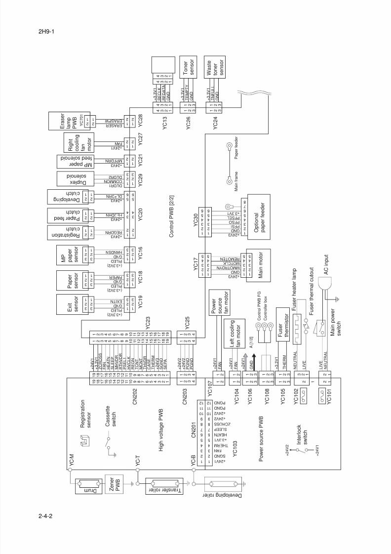
8/3/2019 Servi manualKM-2810ENSMR3
http://slidepdf.com/reader/full/servi-manualkm-2810ensmr3 198/202
2H9-1
2-4-2
Y C 1 0 2
Y C 1 0 5
Y C 1 0 8
Y C 1 0 6
Y C 1 0 4
Y C 1
0 7
Y C 1 0 3
Y C 1 0 1
1
2
3
4
5
6
7
8
9
1 0
1 1
1 2
1
2
3
4
5
6
7
8
9
1 0
1 1
1 2
+ 2 4 V 1
S G N D
F A N
T H E R M
+ 3 . 3 V 1
H E A T N
S L E E P
Z C R O S S
+ 2 4 V 2
+ 2 4 V 2
P G N D
P G N D
+ 2 4 V 2
+ 2 4 V 1
+ 2 4 V 3 G N D M M O T R D Y N M O T C L K R E M O T E N
A [ 1 / 2 ]
1 2 3 4 5
1 2 3 4 5
1 2 3 4 5
1 2 3 4 5
Y C 2 0
Y C 2 7
Y C 1 8
Y C 2 1
Y C 2 9
Y C 1 6
Y C 1 9
Y C 1 7
Y C 3 0
Y C 2 8
Y C 2 5
Y C 2 3
C N 2 0 2
C N 2 0 3
C N 2 0 1
P I L E D G N D P A P E R
+ 2 4 V 3 R E G D R N
+ 2 4 V 3 F E D D R N
D U D R 1 C O M M O N D U D R 2
+ 2 4 V 3 D L P D R N
+ 2 4 V 3 M P F D R N
P I L E D G N D H A N D S N
1 2
3 4
5 6
1 2
3 4
5 6
+ 2 4 V 1 F A N
+ 2 4 V 3 G N D P F S I P F S O P F S E L + 3 . 3 V 1
+ 2 4 V 1
+ 3
. 3 V 1
Z C R O S S
F A N
H E A T N
S L E E P
M H V D R
R T H V D R
P S E L 1
H V C L K
R E G N
T C N T
M C N T
T H V D R
C A S E
T H E R M
+ 2 4 V 3
S G N D
S E P A
E R A S E R E R A S P W
1 2
1 2
2 1
2 1
1 2
1 2
1 2
1 2
1 2 3
1 2 3
1 2 3
1 2 3
1 2 3
1 2 3
1 2 3
1 2 3
3 2 1
3 2 1
3 2 1
3 2 1
3 2 1
3 2 1
2 1
2 1
2 1
2 1
2 1
2 1
+ 2 4 V 2
+ 2 4 V 2
P G N D
P G N D
1 2 3 4
1 2 3 4
1 2 3 4
1 2 3 4 1 9
1 8
1 7
1 6
1 5
1 4
1 3
1 2 1 1
Y C - M
Y C - T
Y C - B
1 0 9 8 7 6 5 4 3 2 1
1 9
1 8
1 7
1 6
1 5
1 4
1 3
1 2
1 1
1 0 9 8 7 6 5 4 3 2 1
1 2 3 4 5 6 7 8 9 1 0
1 1
1 2
1 3
1 4
1 5
1 6
1 7
1 8
1 9
1 2 3 4 5 6 7 8 9 1 0 1 1
1 2
1 3
1 4
1 5
1 6
1 7
1 8
1 9
P I L E D G N D E X I T N
1 2 3 4 5 6
1 2 3 4 5 6
1 2 3
1 2 3
1 2 3
1 2 3
1 2 3
1 2 3
2 1
3 2 1
L I V E
+ 3
. 3 V 1
T H E R M
+ 2 4 V 1
F A N
+ 2 4 V 1
F A N
1 2
1 2
1 2
1 2
2 1
2 1
L I V E
N E U T R A L
N E U T R A L
+ 3
. 3 V 1
T E
M P T Y
G N
D
4 3 2 1
4 3 2 1
4 3 2 1
4 3 2 1
+ 3
. 3 V 1
T N
F U L L
G N
D
1 2 3
1 2 3
1 2 3
1 2 3
Y C 2 4
Y C 1 3
Y C 2 6
+ 3
. 3 V 1
R F
C L K
R F
D A T A
G N
D
Y C 7 0 1
1 2 3 4 5 6 7 8
( + 3 . 3 V 2 )
( + 3 . 3 V 2 )
( + 3 . 3 V 2 )
+ 2 4 V 1
G N D
A C i n p u t
D r u m T r a n s f e r r o l l e r D e v e l o p i n g r o l l e r
L e f t c o o l i n g
f a n m o t o r
P o w e r
s o u r c e
f a n m o t o r
M a i n p o w e r
s w i t c h
I n t e r l o c k
s w i t c h
M P
p a p e r
s e n s o r
P a p e r
s e n s o r
R e g i s t r a t i o n c l u t c h
P a p e r f e e d c l u t c h
D e v e l o p i n g c l u t c h
D u p l e x s o l e n o i d
M P p a p e r f e e d s o l e n o i d
H i g h v o l t a g e P W B
C a s s e t t e
s w i t c h
R e g i s t r a t i o n
s e n s o r
P o w e r s o u r c e P W B
M a i n m o t o r
O p t i o n a l
p a p e r f e e d e r
C o n t r o l P W B [ 2 / 2 ]
R i g h t
c o o l i n g
f a n
m o t o r
F u s e r
t h e r m i s t o r F
u s e r t h e r m
a l c u t o u t
F u s e r h e a t e r l a m p
C o n
t r o l P W B F G
M a
i n f r a m e
P a p e r
f e e
d e r
C o n
t r o l l e r
b o x
T o n e r
s e n s o r
W a s t e
t o n e r
s e n s o r
E r a s e r
l a m p
P W B
E x i t
s e n s o r
Z e n e r
P W
B
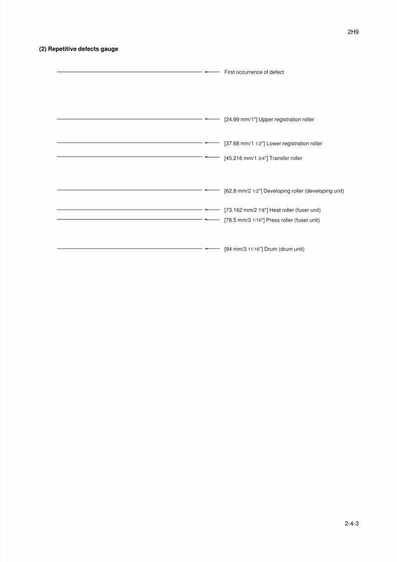
8/3/2019 Servi manualKM-2810ENSMR3
http://slidepdf.com/reader/full/servi-manualkm-2810ensmr3 199/202
2H9
2-4-3
(2) Repetitive defects gauge
First occurrence of defect
[24.99 mm/1"] Upper registration roller
[37.68 mm/1 1/2"] Lower registration roller
[62.8 mm/2 1/2"] Developing roller (developing unit)
[45.216 mm/1 3/4"] Transfer roller
[73.162 mm/2 7/8"] Heat roller (fuser unit)
[78.5 mm/3 1/16"] Press roller (fuser unit)
[94 mm/3 11/16"] Drum (drum unit)

8/3/2019 Servi manualKM-2810ENSMR3
http://slidepdf.com/reader/full/servi-manualkm-2810ensmr3 200/202
2H9-1
2-4-4
(3) Maintenance parts list
Maintenance part namePart No.
Alternative
part No.
Fig.
No.Ref. No.
Name used in service Name used in parts list
Maintenance kit MK-132/MAINTENANCE KIT (OPTION) 1702H97US0 072H97US 15 -
DK-150 - -
DV-132(U) - -Maintenance kit MK-130/MAINTENANCE KIT (OPTION) 1702H98EU0 072H98EU 15 -
DK-150 - -
DV-130(E) - -
Maintenance kit MK-134/MAINTENANCE KIT (OPTION) 1702H98AS0 072H98AS 15 -
DK-150 - -
DV-134(AO) - -

8/3/2019 Servi manualKM-2810ENSMR3
http://slidepdf.com/reader/full/servi-manualkm-2810ensmr3 201/202

8/3/2019 Servi manualKM-2810ENSMR3
http://slidepdf.com/reader/full/servi-manualkm-2810ensmr3 202/202