Series - Shuns RF Mems Switch
10
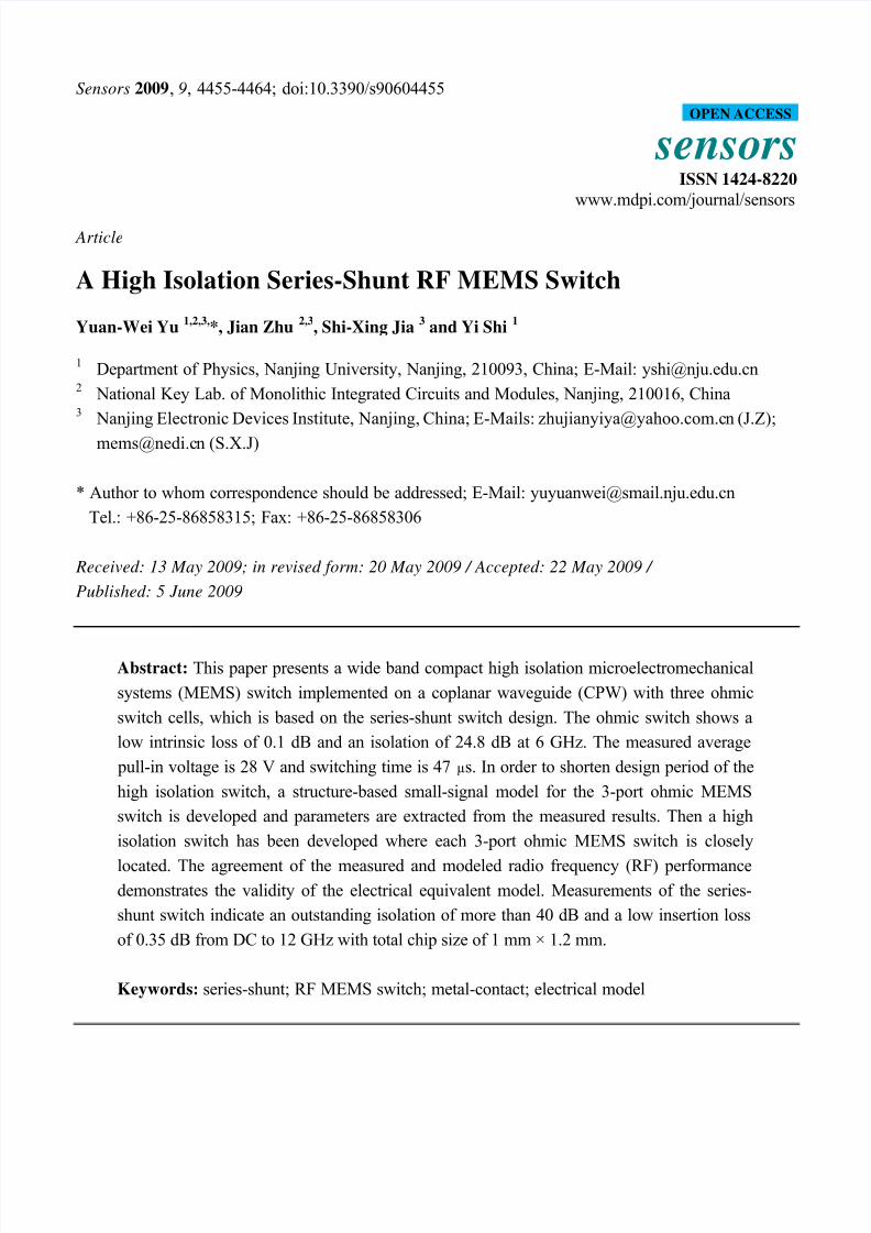
Sensors 2009, 9, 4455-4464; doi:10.3390/s90604455 sensors ISSN 1424-8220 www.mdpi.com/journal/sensors Article A High Isolation Series-Shunt RF MEMS Switch Yuan-Wei Yu 1,2,3, *, Jian Zhu 2,3 , Shi-Xing Jia 3 and Yi Shi 1 1 Department of Physics, Nanjing University, Nanjing, 210093, China; E-Mail: [email protected] 2 National Key Lab. of Monolithic Integrated Circuits and Modules, Nanjing, 210016, China 3 Nanjing Electronic Devices Institute, Nanjing, China; E-Mails: [email protected] n (J.Z); [email protected] n (S.X.J) * Author to whom correspondence should be addressed; E-Mail: [email protected] Tel.: +86-25-86858315; Fax: +86-25-86858306 Received: 13 May 2009; in revised form: 20 May 2009 / Accepted: 22 May 2009 / Published: 5 June 2009 Abstract: This paper presents a wide band compact high isolation microelectromechanical systems (MEMS) switch implemented on a coplanar waveguide (CPW) with three ohmic switch cells, which is based on the series-shunt switch design. The ohmic switch shows a low intrinsic loss of 0.1 dB and an isolation of 24.8 dB at 6 GHz. The measured average pull-in voltage is 28 V and switching time is 47 µs. In order to shorten design period of the high isolation switch, a structure-based small-signal model for the 3-port ohmic MEMS switch is developed and parameters are extracted from the measured results. Then a high isolation switch has been developed where each 3-port ohmic MEMS switch is closely located. The agreement of the measured and modeled radio frequency (RF) performance demonstrates the validity of the electrical equivalent model. Measurements of the series- shunt switch indicate an outstanding isolation of more than 40 dB and a low insertion loss of 0.35 dB from DC to 12 GHz with total chip size of 1 mm × 1.2 mm. Keywords: series-shunt; RF MEMS switch; metal-contact; electrical model OPEN ACCESS
-
Upload
ha-phuong-nguyen -
Category
Documents
-
view
254 -
download
0
Transcript of Series - Shuns RF Mems Switch
8/8/2019 Series - Shuns RF Mems Switch
http://slidepdf.com/reader/full/series-shuns-rf-mems-switch 1/10
Sensors 2009, 9, 4455-4464; doi:10.3390/s90604455
sensorsISSN 1424-8220
www.mdpi.com/journal/sensors
Article
A High Isolation Series-Shunt RF MEMS Switch
Yuan-Wei Yu1,2,3,
*, Jian Zhu2,3
, Shi-Xing Jia3
and Yi Shi1
1 Department of Physics, Nanjing University, Nanjing, 210093, China; E-Mail: [email protected] National Key Lab. of Monolithic Integrated Circuits and Modules, Nanjing, 210016, China3 Nanjing Electronic Devices Institute, Nanjing, China; E-Mails: [email protected] (J.Z);
[email protected] (S.X.J)
* Author to whom correspondence should be addressed; E-Mail: [email protected]
Tel.: +86-25-86858315; Fax: +86-25-86858306
Received: 13 May 2009; in revised form: 20 May 2009 / Accepted: 22 May 2009 /
Published: 5 June 2009
Abstract: This paper presents a wide band compact high isolation microelectromechanical
systems (MEMS) switch implemented on a coplanar waveguide (CPW) with three ohmic
switch cells, which is based on the series-shunt switch design. The ohmic switch shows a
low intrinsic loss of 0.1 dB and an isolation of 24.8 dB at 6 GHz. The measured average
pull-in voltage is 28 V and switching time is 47 µs. In order to shorten design period of the
high isolation switch, a structure-based small-signal model for the 3-port ohmic MEMS
switch is developed and parameters are extracted from the measured results. Then a high
isolation switch has been developed where each 3-port ohmic MEMS switch is closely
located. The agreement of the measured and modeled radio frequency (RF) performancedemonstrates the validity of the electrical equivalent model. Measurements of the series-
shunt switch indicate an outstanding isolation of more than 40 dB and a low insertion loss
of 0.35 dB from DC to 12 GHz with total chip size of 1 mm × 1.2 mm.
Keywords: series-shunt; RF MEMS switch; metal-contact; electrical model
OPEN ACCESS
8/8/2019 Series - Shuns RF Mems Switch
http://slidepdf.com/reader/full/series-shuns-rf-mems-switch 2/10
Sensors 2009, 9 4456
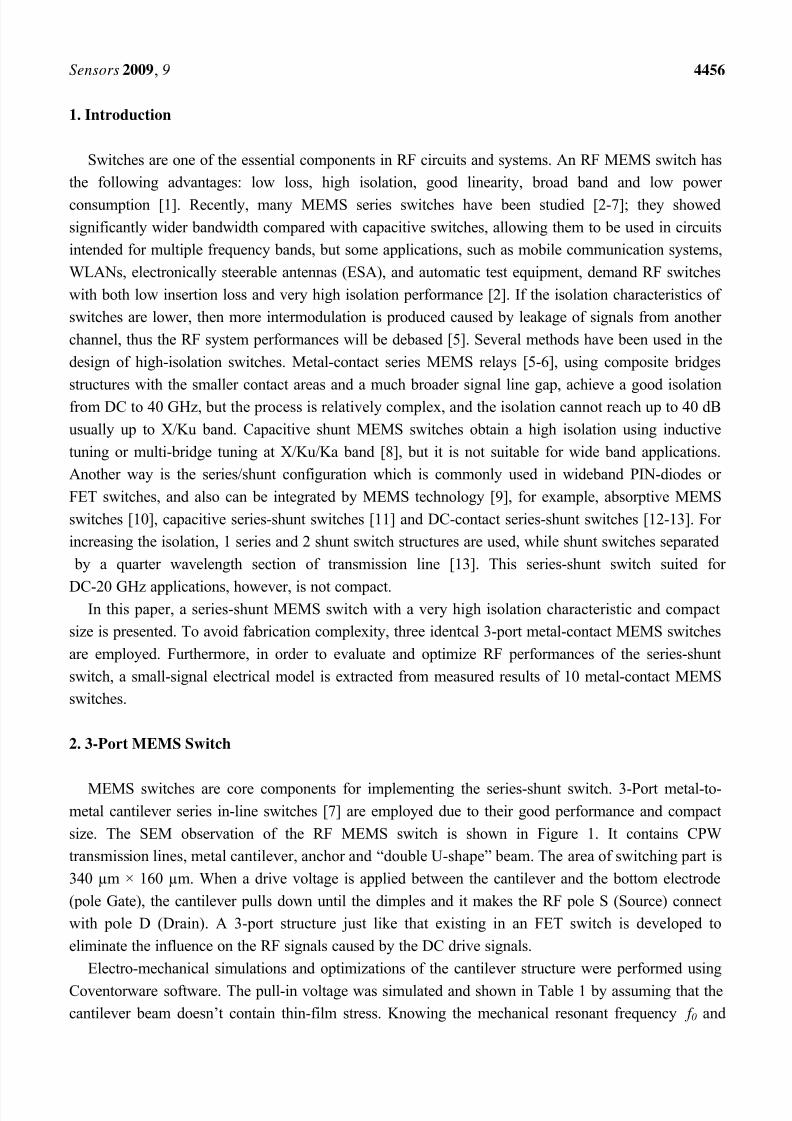
1. Introduction
Switches are one of the essential components in RF circuits and systems. An RF MEMS switch has
the following advantages: low loss, high isolation, good linearity, broad band and low power
consumption [1]. Recently, many MEMS series switches have been studied [2-7]; they showed
significantly wider bandwidth compared with capacitive switches, allowing them to be used in circuits
intended for multiple frequency bands, but some applications, such as mobile communication systems,
WLANs, electronically steerable antennas (ESA), and automatic test equipment, demand RF switches
with both low insertion loss and very high isolation performance [2]. If the isolation characteristics of
switches are lower, then more intermodulation is produced caused by leakage of signals from another
channel, thus the RF system performances will be debased [5]. Several methods have been used in the
design of high-isolation switches. Metal-contact series MEMS relays [5-6], using composite bridges
structures with the smaller contact areas and a much broader signal line gap, achieve a good isolationfrom DC to 40 GHz, but the process is relatively complex, and the isolation cannot reach up to 40 dB
usually up to X/Ku band. Capacitive shunt MEMS switches obtain a high isolation using inductive
tuning or multi-bridge tuning at X/Ku/Ka band [8], but it is not suitable for wide band applications.
Another way is the series/shunt configuration which is commonly used in wideband PIN-diodes or
FET switches, and also can be integrated by MEMS technology [9], for example, absorptive MEMS
switches [10], capacitive series-shunt switches [11] and DC-contact series-shunt switches [12-13]. For
increasing the isolation, 1 series and 2 shunt switch structures are used, while shunt switches separated
by a quarter wavelength section of transmission line [13]. This series-shunt switch suited for
DC-20 GHz applications, however, is not compact.In this paper, a series-shunt MEMS switch with a very high isolation characteristic and compact
size is presented. To avoid fabrication complexity, three identcal 3-port metal-contact MEMS switches
are employed. Furthermore, in order to evaluate and optimize RF performances of the series-shunt
switch, a small-signal electrical model is extracted from measured results of 10 metal-contact MEMS
switches.
2. 3-Port MEMS Switch
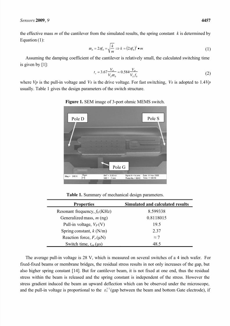
MEMS switches are core components for implementing the series-shunt switch. 3-Port metal-to-metal cantilever series in-line switches [7] are employed due to their good performance and compact
size. The SEM observation of the RF MEMS switch is shown in Figure 1. It contains CPW
transmission lines, metal cantilever, anchor and “double U-shape” beam. The area of switching part is
340 µm × 160 µm. When a drive voltage is applied between the cantilever and the bottom electrode
(pole Gate), the cantilever pulls down until the dimples and it makes the RF pole S (Source) connect
with pole D (Drain). A 3-port structure just like that existing in an FET switch is developed to
eliminate the influence on the RF signals caused by the DC drive signals.
Electro-mechanical simulations and optimizations of the cantilever structure were performed using
Coventorware software. The pull-in voltage was simulated and shown in Table 1 by assuming that the
cantilever beam doesn’t contain thin-film stress. Knowing the mechanical resonant frequency f 0 and
8/8/2019 Series - Shuns RF Mems Switch
http://slidepdf.com/reader/full/series-shuns-rf-mems-switch 3/10
Sensors 2009, 9 4457
the effective mass m of the cantilever from the simulated results, the spring constant k is determined by
Equation (1):
m f k m
k f
2000 22 (1)
Assuming the damping coefficient of the cantilever is relatively small, the calculated switching timeis given by [1]:
00
584.067.3 f V
V
V
V t
S
P
S
Ps
(2)
where Vp is the pull-in voltage and Vs is the drive voltage. For fast switching, Vs is adopted to 1.4Vp
usually. Table 1 gives the design parameters of the switch structure.
Figure 1. SEM image of 3-port ohmic MEMS switch.
Table 1. Summary of mechanical design parameters.
Properties Simulated and calculated results
Resonant frequency, f 0 (KHz) 8.599338
Generalized mass, m (ng) 0.8118015
Pull-in voltage, V P (V) 19.5
Spring constant, k (N/m) 2.37
Reaction force, F r (µN) ≈ 7
Switch time, t on (µs) 48.5
The average pull-in voltage is 28 V, which is measured on several switches of a 4 inch wafer. For
fixed-fixed beams or membrane bridges, the residual stress results in not only increases of the gap, but
also higher spring constant [14]. But for cantilever beam, it is not fixed at one end, thus the residual
stress within the beam is released and the spring constant is independent of the stress. However the
stress gradient induced the beam an upward deflection which can be observed under the microscope,and the pull-in voltage is proportional to the 2/30g (gap between the beam and bottom Gate electrode), if
Pole SPole D
Pole G
8/8/2019 Series - Shuns RF Mems Switch
http://slidepdf.com/reader/full/series-shuns-rf-mems-switch 4/10
Sensors 2009, 9 4458
a deflection of 0.82 µm is assumed, then the simulated pull-in voltage agrees well with the
measurements.
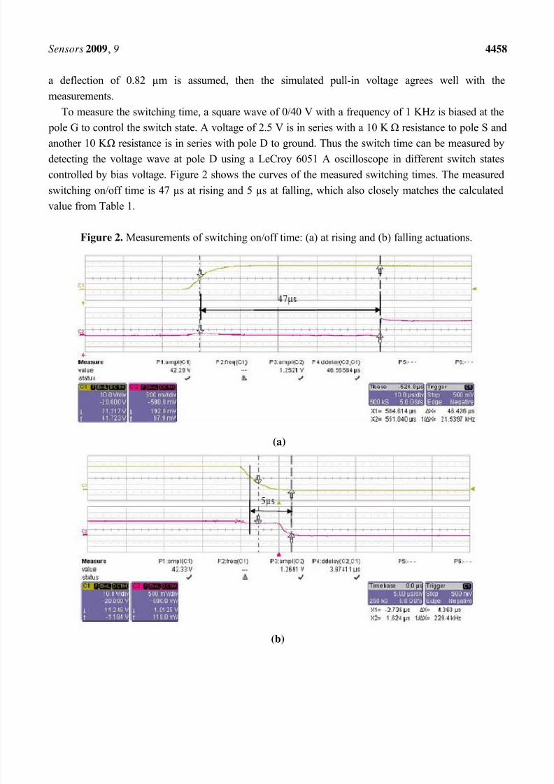
To measure the switching time, a square wave of 0/40 V with a frequency of 1 KHz is biased at the
pole G to control the switch state. A voltage of 2.5 V is in series with a 10 K Ω resistance to pole S and
another 10 K Ω resistance is in series with pole D to ground. Thus the switch time can be measured by
detecting the voltage wave at pole D using a LeCroy 6051 A oscilloscope in different switch states
controlled by bias voltage. Figure 2 shows the curves of the measured switching times. The measured
switching on/off time is 47 µs at rising and 5 µs at falling, which also closely matches the calculated
value from Table 1.
Figure 2. Measurements of switching on/off time: (a) at rising and (b) falling actuations.
(a)
(b)
8/8/2019 Series - Shuns RF Mems Switch
http://slidepdf.com/reader/full/series-shuns-rf-mems-switch 5/10
Sensors 2009, 9 4459
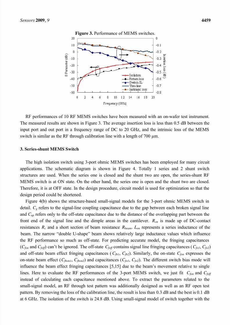
Figure 3. Performance of MEMS switches.
RF performances of 10 RF MEMS switches have been measured with an on-wafer test instrument.
The measured results are shown in Figure 3. The average insertion loss is less than 0.5 dB between the
input port and out port in a frequency range of DC to 20 GHz, and the intrinsic loss of the MEMS
switch is similar as the RF through calibration line with a length of 700 µm.
3. Series-shunt MEMS Switch
The high isolation switch using 3-port ohmic MEMS switches has been employed for many circuit
applications. The schematic diagram is shown in Figure 4. Totally 1 series and 2 shunt switchstructures are used. When the series one is closed and the shunt two are open, the series-shunt RF
MEMS switch is at ON state. On the other hand, the series one is open and the shunt two are closed.
Therefore, it is at OFF state. In the design procedure, circuit model is used for optimization so that the
design period could be shortened.
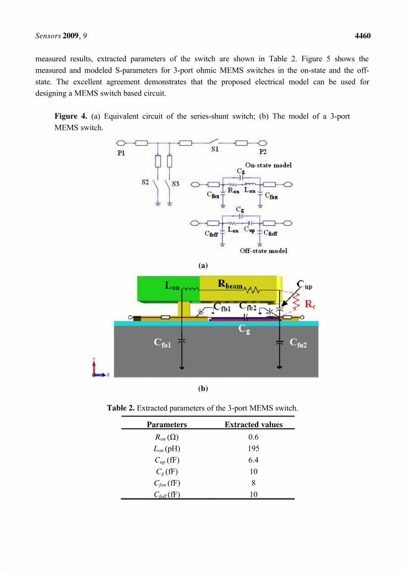
Figure 4(b) shows the structure-based small-signal models for the 3-port ohmic MEMS switch in
detail. C g refers to the signal-line coupling capacitance due to the gap between each broken signal line
and C up refers only to the off-state capacitance due to the distance of the overlapping part between the
front end of the signal line and the dimple areas in the cantilever. Ron is made up of DC-contact
resistances Rc and a short section of beam resistance Rbeam. Lon represents a series inductance of the beam. The narrow “double U-shape” beam shows relatively large inductance values which influence
the RF performance so much as off-state. For predicting accurate model, the fringing capacitances
(C fon and C foff ) can’t be ignored. The off-state C foff contains signal line fringing capacitances (C fo1, C fo2)
and off-state beam effect fringing capacitances (C fb1, C fb2). Similarly, the on-state C fon expresses the
on-state beam effect (C fbon1, C fbon2) and capacitances (C fo1, C fo2). The different switch bias mode will
influence the beam effect fringing capacitances [5,15] due to the beam’s movement relative to single
lines. Here to evaluate the RF performances of the 3-port MEMS switch, we just fit C fon and C foff
instead of calculating each capacitance mentioned above. To extract the parameters related to the
small-signal model, an RF through test pattern was additionally designed as well as an RF open test pattern. By removing the loss of the calibration line, the result is less than 0.3 dB and the best is 0.1 dB
at 6 GHz. The isolation of the switch is 24.8 dB. Using small-signal model of switch together with the
8/8/2019 Series - Shuns RF Mems Switch
http://slidepdf.com/reader/full/series-shuns-rf-mems-switch 6/10
Sensors 2009, 9 4460
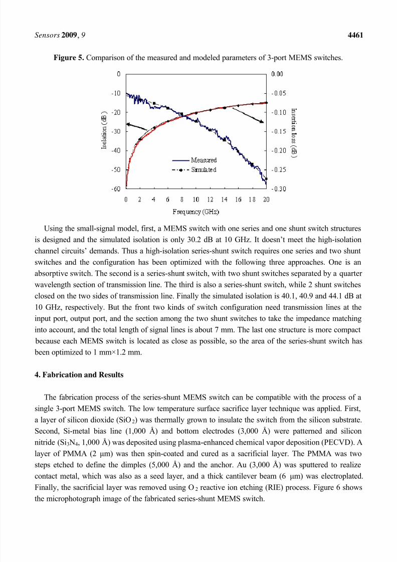
measured results, extracted parameters of the switch are shown in Table 2. Figure 5 shows the
measured and modeled S-parameters for 3-port ohmic MEMS switches in the on-state and the off-
state. The excellent agreement demonstrates that the proposed electrical model can be used for
designing a MEMS switch based circuit.
Figure 4. (a) Equivalent circuit of the series-shunt switch; (b) The model of a 3-port
MEMS switch.
(a)
(b)
Table 2. Extracted parameters of the 3-port MEMS switch.
Parameters Extracted values
Ron (Ω) 0.6
Lon (pH) 195
C up (fF) 6.4
C g (fF) 10
C fon (fF) 8
C foff (fF) 10
8/8/2019 Series - Shuns RF Mems Switch
http://slidepdf.com/reader/full/series-shuns-rf-mems-switch 7/10
Sensors 2009, 9 4461
Figure 5. Comparison of the measured and modeled parameters of 3-port MEMS switches.
Using the small-signal model, first, a MEMS switch with one series and one shunt switch structures
is designed and the simulated isolation is only 30.2 dB at 10 GHz. It doesn’t meet the high-isolation
channel circuits’ demands. Thus a high-isolation series-shunt switch requires one series and two shunt
switches and the configuration has been optimized with the following three approaches. One is an
absorptive switch. The second is a series-shunt switch, with two shunt switches separated by a quarter
wavelength section of transmission line. The third is also a series-shunt switch, while 2 shunt switches
closed on the two sides of transmission line. Finally the simulated isolation is 40.1, 40.9 and 44.1 dB at10 GHz, respectively. But the front two kinds of switch configuration need transmission lines at the
input port, output port, and the section among the two shunt switches to take the impedance matching
into account, and the total length of signal lines is about 7 mm. The last one structure is more compact
because each MEMS switch is located as close as possible, so the area of the series-shunt switch has
been optimized to 1 mm×1.2 mm.
4. Fabrication and Results
The fabrication process of the series-shunt MEMS switch can be compatible with the process of asingle 3-port MEMS switch. The low temperature surface sacrifice layer technique was applied. First,
a layer of silicon dioxide (SiO2) was thermally grown to insulate the switch from the silicon substrate.
Second, Si-metal bias line (1,000 Å) and bottom electrodes (3,000 Å) were patterned and silicon
nitride (Si3 N4, 1,000 Å) was deposited using plasma-enhanced chemical vapor deposition (PECVD). A
layer of PMMA (2 μm) was then spin-coated and cured as a sacrificial layer. The PMMA was two
steps etched to define the dimples (5,000 Å) and the anchor. Au (3,000 Å) was sputtered to realize
contact metal, which was also as a seed layer, and a thick cantilever beam (6 μm) was electroplated.
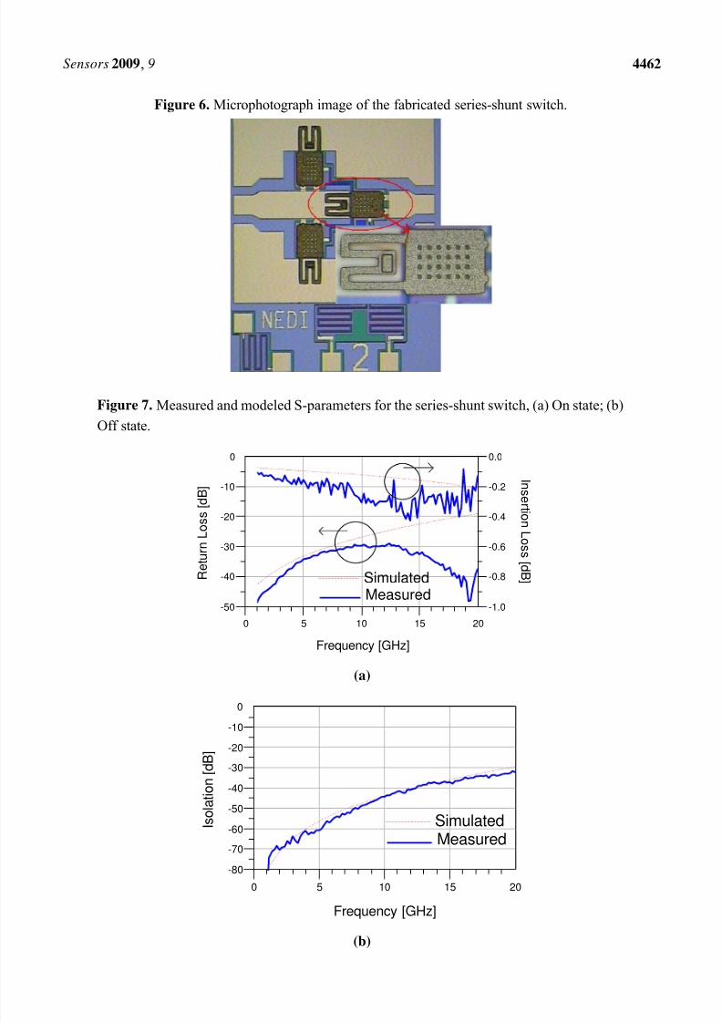
Finally, the sacrificial layer was removed using O2 reactive ion etching (RIE) process. Figure 6 shows
the microphotograph image of the fabricated series-shunt MEMS switch.
8/8/2019 Series - Shuns RF Mems Switch
http://slidepdf.com/reader/full/series-shuns-rf-mems-switch 8/10
Sensors 2009, 9 4462
Figure 6. Microphotograph image of the fabricated series-shunt switch.
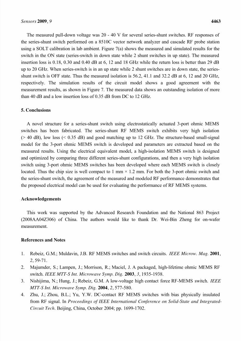
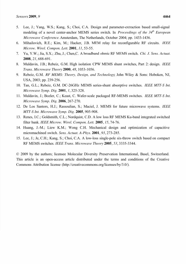
Figure 7. Measured and modeled S-parameters for the series-shunt switch, (a) On state; (b)
Off state.
5 10 150 20
-40
-30
-20
-10
-50
0
-0.8
-0.6
-0.4
-0.2
-1.0
0.0
Frequency [GHz]
I n s er t i on
L o s s
[ d B ] R
e t u r n L
o s s [ d B ]
SimulatedMeasured
(a)
5 10 150 20
-70
-60
-50
-40
-30
-20
-10
-80
0
Frequency [GHz]
I s o l a t i o n [ d B ]
SimulatedMeasured
(b)
8/8/2019 Series - Shuns RF Mems Switch
http://slidepdf.com/reader/full/series-shuns-rf-mems-switch 9/10
Sensors 2009, 9 4463
The measured pull-down voltage was 20 - 40 V for several series-shunt switches. RF responses of
the series-shunt switch performed on a 8510C vector network analyzer and cascade RF probe station
using a SOLT calibration in lab ambient. Figure 7(a) shows the measured and simulated results for the
switch in the ON state (series-switch in down state while 2 shunt switches in up state). The measured
insertion loss is 0.18, 0.30 and 0.40 dB at 6, 12 and 18 GHz while the return loss is better than 29 dB
up to 20 GHz. When series-switch is in an up state while 2 shunt switches are in down state, the series-
shunt switch is OFF state. Thus the measured isolation is 56.2, 41.1 and 32.2 dB at 6, 12 and 20 GHz,
respectively. The simulation results of the circuit model shows a good agreement with the
measurement results, as shown in Figure 7. The measured data shows an outstanding isolation of more
than 40 dB and a low insertion loss of 0.35 dB from DC to 12 GHz.
5. Conclusions
A novel structure for a series-shunt switch using electrostatically actuated 3-port ohmic MEMS
switches has been fabricated. The series-shunt RF MEMS switch exhibits very high isolation
(> 40 dB), low loss (< 0.35 dB) and good matching up to 12 GHz. The structure-based small-signal
model for the 3-port ohmic MEMS switch is developed and parameters are extracted based on the
measured results. Using the electrical equivalent model, a high-isolation MEMS switch is designed
and optimized by comparing three different series-shunt configurations, and then a very high isolation
switch using 3-port ohmic MEMS switches has been developed where each MEMS switch is closely
located. Thus the chip size is well compact to 1 mm × 1.2 mm. For both the 3-port ohmic switch and
the series-shunt switch, the agreement of the measured and modeled RF performance demonstrates thatthe proposed electrical model can be used for evaluating the performance of RF MEMS systems.
Acknowledgements
This work was supported by the Advanced Research Foundation and the National 863 Project
(2008AA04Z306) of China. The authors would like to thank Dr. Wei-Bin Zheng for on-wafer
measurement.
References and Notes
1. Rebeiz, G.M.; Muldavin, J.B. RF MEMS switches and switch circuits. IEEE Microw. Mag. 2001,
2, 59-71.
2. Majumder, S.; Lampen, J.; Morrison, R.; Maciel, J. A packaged, high-lifetime ohmic MEMS RF
switch. IEEE MTT-S Int. Microwave Symp. Dig. 2003, 3, 1935-1938.
3. Nishijima, N.; Hung, J.; Rebeiz, G.M. A low-voltage high contact force RF-MEMS switch. IEEE
MTT-S Int. Microwave Symp. Dig. 2004, 2, 577-580.
4. Zhu, J.; Zhou, B.L.; Yu, Y.W. DC-contact RF MEMS switches with bias physically insulated
from RF signal. In Proceedings of IEEE International Conference on Solid-State and Integrated-
Circuit Tech. Beijing, China, October 2004; pp. 1699-1702.
8/8/2019 Series - Shuns RF Mems Switch
http://slidepdf.com/reader/full/series-shuns-rf-mems-switch 10/10
Sensors 2009, 9 4464
5. Lee, J.; Yang, W.S.; Kang, S.; Choi, C.A. Design and parameter-extraction based small-signal
modeling of a novel center-anchor MEMS series switch. In Proceedings of the 34th
European
Microwave Conference. Amsterdam, The Netherlands, October 2004; pp. 1433-1436.
6. Mihailovich, R.E.; Kim, M.; Hacker, J.B. MEM relay for reconfigurable RF circuits. IEEE
Microw. Wirel. Compon. Lett. 2001, 11, 53-55.
7. Yu, Y.W.; Jia, S.X.; Zhu, J.; Chen,C. A broadband ohmic RF MEMS switch. Chi. J. Sens. Actuat.
2008, 21, 688-691.
8. Muldavin, J.B.; Rebeiz, G.M. High isolation CPW MEMS shunt switches, Part 2: design. IEEE
Trans. Microwave Theory 2000, 48, 1053-1056.
9. Rebeiz, G.M. RF MEMS: Theory, Design, and Technology; John Wiley & Sons: Hoboken, NJ,
USA, 2003; pp. 239-256.
10. Tan, G.L.; Rebeiz, G.M. DC-26GHz MEMS series-shunt absorptive switches. IEEE MTT-S Int.
Microwave Symp. Dig. 2001
,1, 325-328.11. Muldavin, J.; Bozler, C.; Keast, C. Wafer-scale packaged RF-MEMS switches. IEEE MTT-S Int.
Microwave Symp. Dig. 2006, 267-270.
12. De Los Santors, H.J.; Rassoulian, S.; Maciel, J. MEMS for future microwave systems. IEEE
MTT-S Int. Microwave Symp. Dig. 2005, 905-908.
13. Renes, I.C.; Goldsmith, C.L.; Nordquist, C.D. A low loss RF MEMS Ku-band integrated switched
filter bank. IEEE Microw. Wirel. Compon. Lett. 2005, 15, 74-76.
14. Huang, J.-M.; Liew K.M.; Wong C.H. Mechanical design and optimization of capacitive
micromachined switch. Sens. Actuat. A-Phys. 2001, 93, 273-285.
15. Lee, J.; Je, C.H.; Kang, S.; Choi, C.A. A low-loss single-pole six-throw switch based on compactRF MEMS switches. IEEE Trans. Microwave Theory 2005, 53, 3335-3344.
© 2009 by the authors; licensee Molecular Diversity Preservation International, Basel, Switzerland.
This article is an open-access article distributed under the terms and conditions of the Creative
Commons Attribution license (http://creativecommons.org/licenses/by/3.0/).