Selection Guide 1.1 kW – 400 kW VLT® HVAC Drive FC 102
40
Selection Guide 1.1 kW – 400 kW VLT® HVAC Drive FC 102 www.danfoss.com/drives Energy efficiency Save energy and money with up to 98% efficient VLT® drives. 98%
Transcript of Selection Guide 1.1 kW – 400 kW VLT® HVAC Drive FC 102

Selection Guide 1.1 kW – 400 kW VLT® HVAC Drive FC 102
www.danfoss.com/drives
Energy efficiencySave energy and money with up to 98% efficient VLT® drives.
98%

2 VLT® HVAC Drive | 1.1 kW – 400 kW |

The VLT® HVAC drive is a dedicated, globally
supported drive that combines flexibility and
efficiency in a package designed to minimize total
system and lifecycle costs in HVAC applications.
Designed to provide the highest efficiency solution with both
asynchronous and permanent magnet motors from all major suppliers, the
VLT® HVAC drive is the leading drive for heating, ventilation and air conditioning
systems. The motor independent drive can be installed in any fan or pump
system and provide years of reliable, maintenance free operation.
When used in Danfoss’ EC+ concept, the HVAC drive plays a significant part in
enabling building owners to meet ever stricter efficiency and environmental
legislation effectively and cost efficiently.
Every VLT® HVAC Drive is based on 25 years of experience and innovation. Easy to use, all models follow the same
basic design and operating principle. Once you know one, you know them all.
This selection guide helps you to choose and configure your perfect drive for
applications from 1.1-400 kW.
Dedicated drive for highest energy efficiency
and reliability
1.1 – 400 kW
The drives up 1.4 MW are handled
in a separate brochure
3 | 1.1 kW – 400 kW | VLT® HVAC Drive
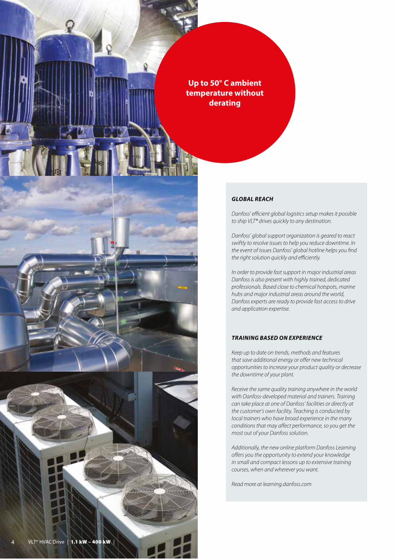
Up to 50° C ambient temperature without
derating
GLOBAL REACH
Danfoss’ efficient global logistics setup makes it possible to ship VLT® drives quickly to any destination.
Danfoss’ global support organization is geared to react swiftly to resolve issues to help you reduce downtime. In the event of issues Danfoss’ global hotline helps you find the right solution quickly and efficiently.
In order to provide fast support in major industrial areas Danfoss is also present with highly trained, dedicated professionals. Based close to chemical hotspots, marine hubs and major industrial areas around the world, Danfoss experts are ready to provide fast access to drive and application expertise.
TRAINING BASED ON EXPERIENCE
Keep up to date on trends, methods and features that save additional energy or offer new technical opportunities to increase your product quality or decrease the downtime of your plant.
Receive the same quality training anywhere in the world with Danfoss-developed material and trainers. Training can take place at one of Danfoss’ facilities or directly at the customer’s own facility. Teaching is conducted by local trainers who have broad experience in the many conditions that may affect performance, so you get the most out of your Danfoss solution.
Additionally, the new online platform Danfoss Learning offers you the opportunity to extend your knowledge in small and compact lessons up to extensive training courses, when and wherever you want.
Read more at learning.danfoss.com
4 VLT® HVAC Drive | 1.1 kW – 400 kW |

VLT® PLATFORM HIGHLIGHTS
• Versatile, flexible, configurable • EMC filters integrated as standard• Asynchronous & PM motor control• 9 fieldbuses supported • Up to 1.4 MW in common voltages• Unique user interface• Globally supported
contact. The unit can also be ordered with optional fuses or circuit breakers in the same package size. Control and power cables are fed in separately at the bottom.
The frequency converters combine a flexible system architecture, which allows them to be adapted to specific applications, with a uniform user interface across all power classes. This allows you to adapt the drive to the exact needs of your specific application. As a result project work and costs are subsequently reduced. The easy to use interface reduces training requirements. The integrated SmartStart guides users quickly and efficiently through the setup process, which results in fewer faults due to configuration and parameterization errors.
Freedom to design efficient systemsHVAC drives are built on a flexible system architecture, which allows them to be adapted to specific applications to provide maximum system efficiency.
Available in a performance range from 1.1 kW to 1.4 MW the FC 102 series can control nearly all standard industrial motor technologies, including permanent magnet motors, copper rotor motors and direct line PM.
The frequency converter is designed to work with all common supply voltages: 200, 380-480 V, 525-600 V and 690 V.
As a result, system designers, OEMs and end users can connect the drive to their chosen motor and reduce project costs with a solution that performs to the highest standards.
Flexible, modular and adaptable Built to last
The VLT® HVAC Drive is built on a flexible, modular design concept to provide an extraordinarily versatile motor control solution. Equipped with a wide range of HVAC features owners can achieve optimal fan and pump control, higher quality output and reduce costs related to spare parts and service, and much more.
Built-in EMC filters VLT® HVAC Drive units are equipped with integrated DC link chokes and EMC filters as standard features. This enables them to reduce grid pollution and eliminate the cost and effort of fitting external EMC components and related wiring.
Reduce costs with compact drives A compact design and efficient heat management enable the drives to take up less space in control rooms and panels in all kinds of environments. Especially impressive is the 315 kW, 400 V version, which is among the smallest in its power class on the market today, and is available in an IP 54 enclosure.
Compact dimensions are also an advantage in applications where drive space is restricted. This makes it possible for designers to develop smaller applications without being forced to compromise on protection and grid quality. For example, the D frame versions of the VLT® HVAC Drive FC 102 from 110-400 kW are 25-68 % smaller than equivalent drives.
The IP 20 version is optimized for cabinet mounting and features covered power terminals to prevent accidental
5 | 1.1 kW – 400 kW | VLT® HVAC Drive
efficient back channel cooling concept, that also allows to conduct the heat into the outside of the control room. Both methods make it possible to reduce the initial cost of the panel or switch room.
In daily use the benefits are equally clear as the energy consumption related to cooling can be reduced significantly. This means that designers can reduce the size of the air conditioning system, or even eliminate it entirely.
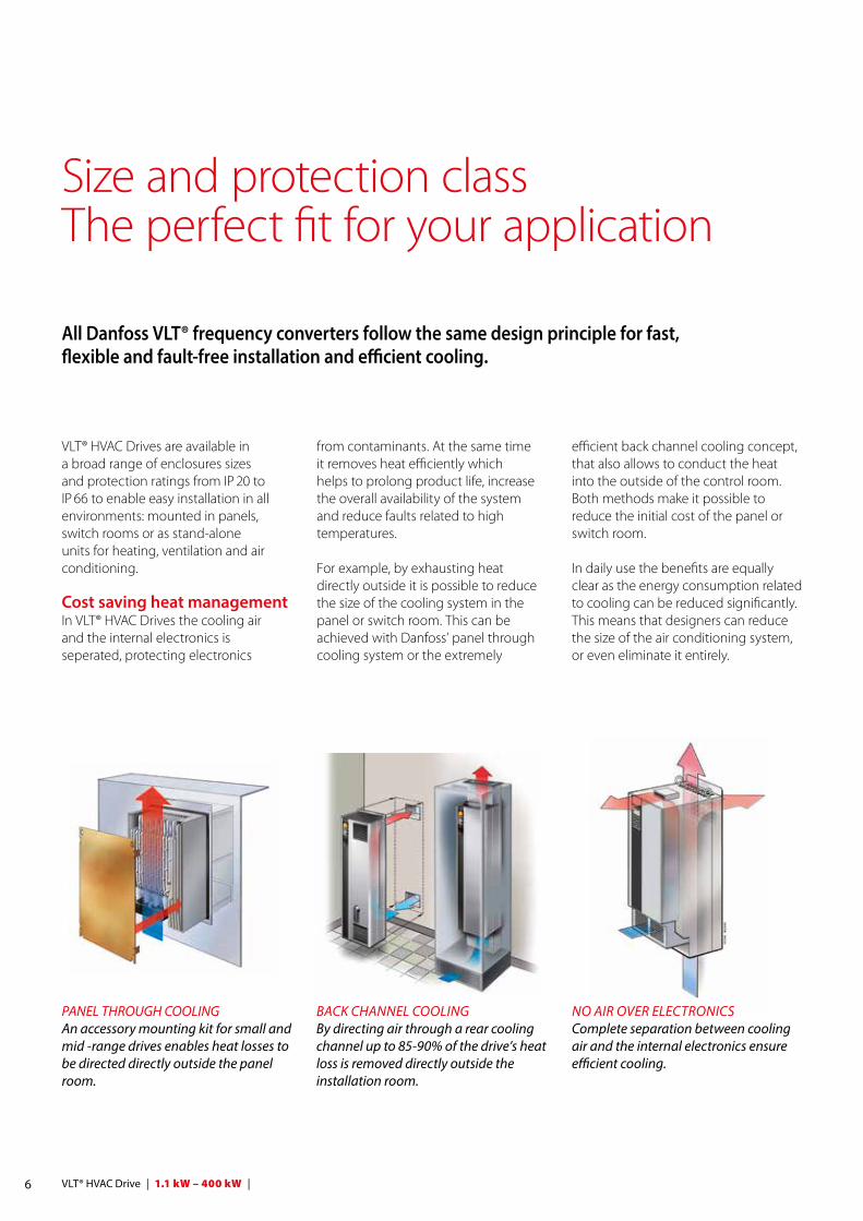
from contaminants. At the same time it removes heat efficiently which helps to prolong product life, increase the overall availability of the system and reduce faults related to high temperatures.
For example, by exhausting heat directly outside it is possible to reduce the size of the cooling system in the panel or switch room. This can be achieved with Danfoss’ panel through cooling system or the extremely
Size and protection class The perfect fit for your application
All Danfoss VLT® frequency converters follow the same design principle for fast, flexible and fault-free installation and efficient cooling.
VLT® HVAC Drives are available in a broad range of enclosures sizes and protection ratings from IP 20 to IP 66 to enable easy installation in all environments: mounted in panels, switch rooms or as stand-alone units for heating, ventilation and air conditioning.
Cost saving heat managementIn VLT® HVAC Drives the cooling air and the internal electronics is seperated, protecting electronics
PANEL THROUGH COOLING An accessory mounting kit for small and mid -range drives enables heat losses to be directed directly outside the panel room.
BACK CHANNEL COOLINGBy directing air through a rear cooling channel up to 85-90% of the drive’s heat loss is removed directly outside the installation room.
NO AIR OVER ELECTRONICSComplete separation between cooling air and the internal electronics ensure efficient cooling.
6 VLT® HVAC Drive | 1.1 kW – 400 kW |
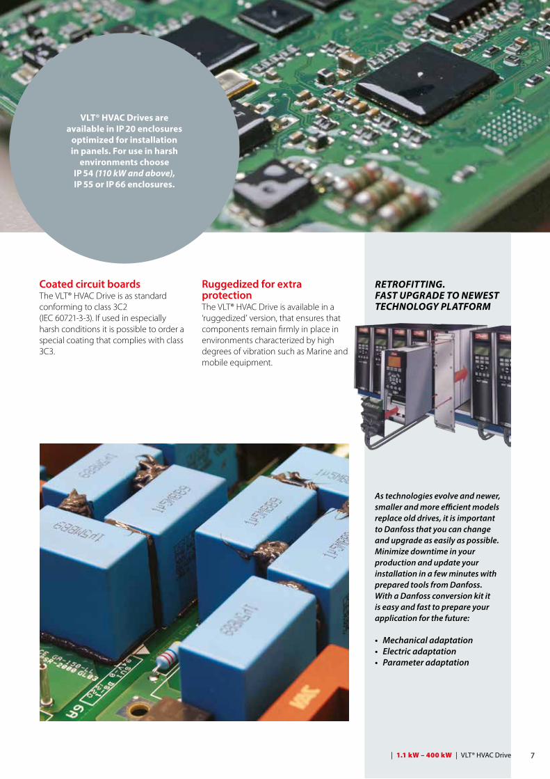
VLT® HVAC Drives are available in IP 20 enclosures
optimized for installation in panels. For use in harsh
environments choose IP 54 (110 kW and above), IP 55 or IP 66 enclosures.
RETROFITTING. FAST UPGRADE TO NEWEST TECHNOLOGY PLATFORM
As technologies evolve and newer, smaller and more efficient models replace old drives, it is important to Danfoss that you can change and upgrade as easily as possible.Minimize downtime in your production and update your installation in a few minutes with prepared tools from Danfoss. With a Danfoss conversion kit it is easy and fast to prepare your application for the future: • Mechanical adaptation• Electric adaptation• Parameter adaptation
Coated circuit boardsThe VLT® HVAC Drive is as standard conforming to class 3C2 (IEC 60721-3-3). If used in especially harsh conditions it is possible to order a special coating that complies with class 3C3.
Ruggedized for extra protectionThe VLT® HVAC Drive is available in a ‘ruggedized’ version, that ensures that components remain firmly in place in environments characterized by high degrees of vibration such as Marine and mobile equipment.
7 | 1.1 kW – 400 kW | VLT® HVAC Drive
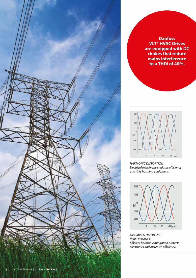
OPTIMISED HARMONIC PERFORMANCEEfficient harmonic mitigation protects electronics and increases efficiency.
HARMONIC DISTORTION Electrical interference reduces efficiency and risks harming equipment.
Danfoss VLT® HVAC Drives
are equipped with DC chokes that reduce mains interference to a THDi of 40%.
8 VLT® HVAC Drive | 1.1 kW – 400 kW |
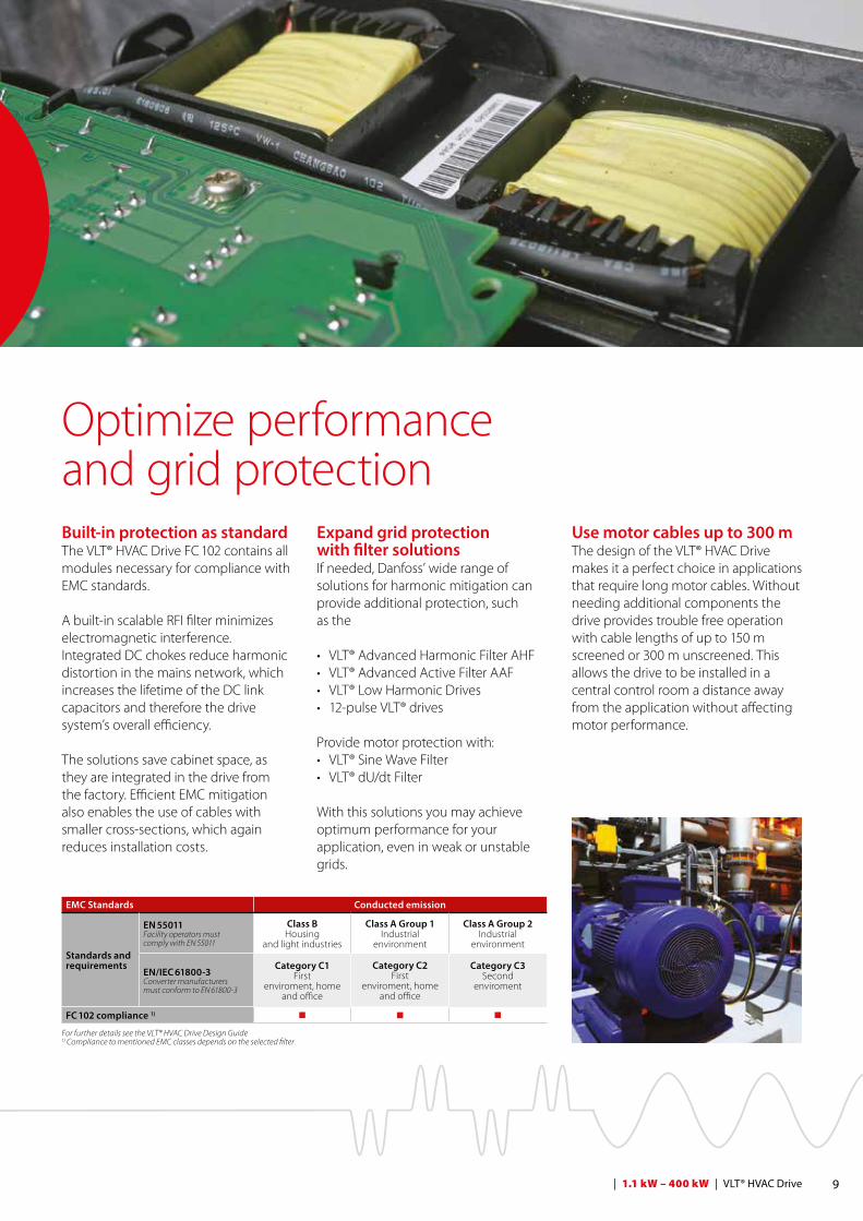
Use motor cables up to 300 mThe design of the VLT® HVAC Drive makes it a perfect choice in applications that require long motor cables. Without needing additional components the drive provides trouble free operation with cable lengths of up to 150 m screened or 300 m unscreened. This allows the drive to be installed in a central control room a distance away from the application without affecting motor performance.
Built-in protection as standardThe VLT® HVAC Drive FC 102 contains all modules necessary for compliance with EMC standards. A built-in scalable RFI filter minimizes electromagnetic interference. Integrated DC chokes reduce harmonic distortion in the mains network, which increases the lifetime of the DC link capacitors and therefore the drive system’s overall efficiency.
The solutions save cabinet space, as they are integrated in the drive from the factory. Efficient EMC mitigation also enables the use of cables with smaller cross-sections, which again reduces installation costs.
Optimize performanceand grid protection
Expand grid protection with filter solutionsIf needed, Danfoss’ wide range of solutions for harmonic mitigation can provide additional protection, such as the
• VLT® Advanced Harmonic Filter AHF • VLT® Advanced Active Filter AAF • VLT® Low Harmonic Drives• 12-pulse VLT® drives
Provide motor protection with:• VLT® Sine Wave Filter• VLT® dU/dt Filter
With this solutions you may achieve optimum performance for your application, even in weak or unstable grids.
9 | 1.1 kW – 400 kW | VLT® HVAC Drive
EMC Standards Conducted emission
Standards and requirements
EN 55011Facility operators must comply with EN 55011
Class BHousing
and light industries
Class A Group 1Industrial
environment
Class A Group 2Industrial
environment
EN/IEC 61800-3Converter manufacturersmust conform to EN 61800-3
Category C1First
enviroment, home and office
Category C2First
enviroment, home and office
Category C3Second
enviroment
FC 102 compliance 1) n n n
For further details see the VLT® HVAC Drive Design Guide1) Compliance to mentioned EMC classes depends on the selected filter
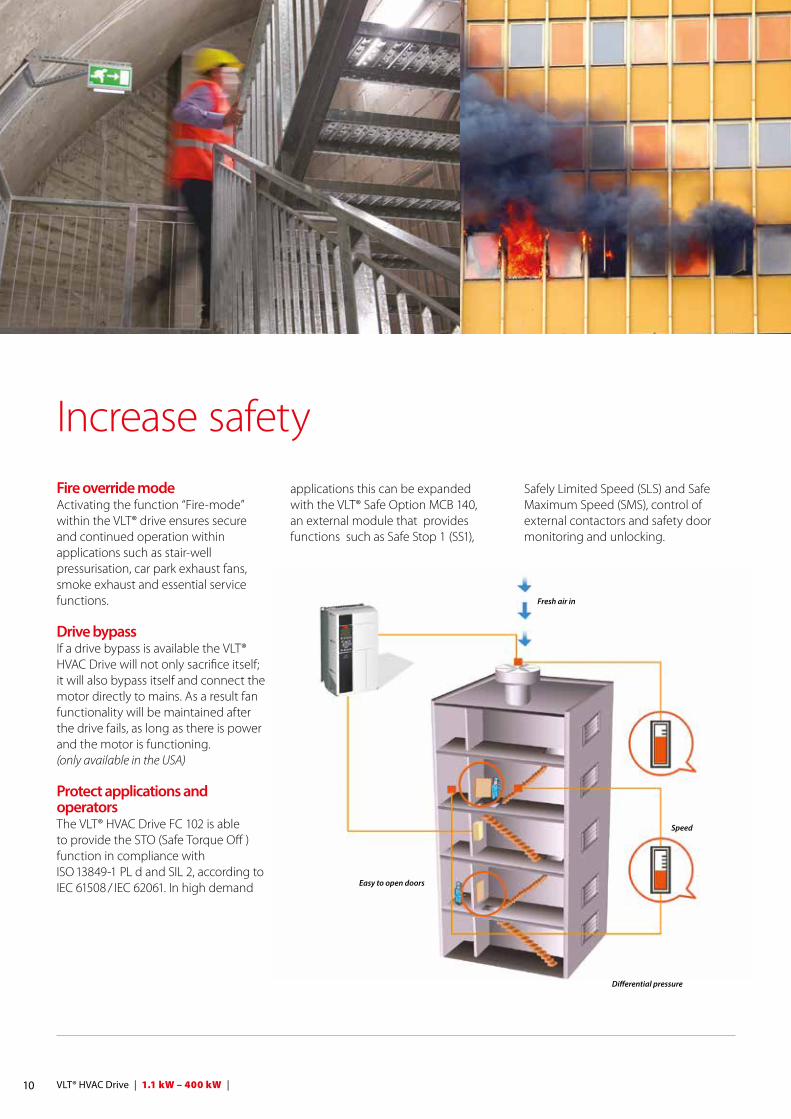
Speed
Differential pressure
Easy to open doors
Fresh air in
Safely Limited Speed (SLS) and Safe Maximum Speed (SMS), control of external contactors and safety door monitoring and unlocking.
applications this can be expanded with the VLT® Safe Option MCB 140, an external module that provides functions such as Safe Stop 1 (SS1),
Increase safetyFire override mode Activating the function “Fire-mode” within the VLT® drive ensures secure and continued operation within applications such as stair-well pressurisation, car park exhaust fans, smoke exhaust and essential service functions.
Drive bypass If a drive bypass is available the VLT® HVAC Drive will not only sacrifice itself; it will also bypass itself and connect the motor directly to mains. As a result fan functionality will be maintained after the drive fails, as long as there is power and the motor is functioning.(only available in the USA) Protect applications and operators The VLT® HVAC Drive FC 102 is able to provide the STO (Safe Torque Off ) function in compliance with ISO 13849-1 PL d and SIL 2, according to IEC 61508 / IEC 62061. In high demand
10 VLT® HVAC Drive | 1.1 kW – 400 kW |
BACnet Change of Value (COV)The standard, passive, BACnet protocol that is embedded in every HVAC drive, can be expanded with the VLT® BACnet Option MCA 109 option.
This add-on enables the drive to support COV. As a result the drive will only communicate if pre-defined set-points are exceeded.
By effectively optimizing communication, the MCA 109 reduces the load on the fieldbus enabling more efficient building management.
Increase productivityWith the wide range of fieldbus options the VLT® HVAC Drive can be easily connected to the fieldbus system of your choice. This makes the HVAC Drive a future-ready solution that can easily be expanded and updated if your needs change.
Danfoss fieldbus options can also be installed as a plug-and-play solution at a later stage, if the production layout demands a new communication platform. This way, you can be confident that you can optimize your plant without being forced to replace your existing drive system.
See the complete list of fieldbuses on page 24.
Nine fieldbuses supported
11 | 1.1 kW – 400 kW | VLT® HVAC Drive

Energy documentationVLT® Energy Box software is the most modern and advanced energy calculation tool available.
It allows energy consumption calculations and comparisons of HVAC fans, pumps and cooling tower applications driven by Danfoss drives and alternative methods of flow control.
The program compares the total operational costs of various traditional systems to operation of the same systems with a VLT® HVAC Drive.
With this program it is easy to evaluate the savings by comparing a VLT® HVAC Drive over other types of capa-city control systems in both new installations as well as retrofit situations.
Complete financial analysisVLT® Energy Box provides a complete financial analysis including:
• Initial cost for the drive system and the alternative system• Installation and hardware costs• Annual maintenance costs and any utility company incentives for energy conservation products• Payback time and accumulated savings• Upload of actual energy
consumption (kWh) and duty cycle from the VLT® HVAC Drive
VLT® Energy Box makes it possible to capture actual energy data from the drives and monitor energy consumption and overall system efficiency.
Energy auditThe VLT® HVAC Drive coupled with Energy Box software enables the package to be used as the Energy Audit equipment for both the estimation and validation of savings.
VLT® HVAC Drive can be interrogated remotely for full energy data, making it easy to monitor your energy savings and return on investment. Monitoring via fieldbus often makes energy meters omissible.
Download VLT® Energy Box www.danfoss.com/energybox
12 VLT® HVAC Drive | 1.1 kW – 400 kW |
Software toolsEasy engineering and setup with VLT® Motion Control Tool MCT 10In addition to operating the drive via LCP (local control panel), VLT® drives can also be configured and monitored with Danfoss own PC software. This provides plant managers with a comprehensive overview of the system at any point in time, adding a new level of flexibility in configuration, monitoring and troubleshooting.
MCT 10 is a windows based engineering tool with a clearly structured interface that provides an instant overview of all the drives in a system of any size. The software runs under Windows and enables data exchange over a traditional RS485 interface, fieldbus (Profibus, Ethernet, etc.) or via USB.
Parameter configuration is possible both online on a connected drive and offline in the tool itself. Additional documentation, such as electrical diagrams or operating manuals, can be embedded in MCT 10. This reduces the risk of incorrect configuration while offering fast access to troubleshooting.
Analyse harmonic distortion with VLT® Harmonic Calculation Software HCS This is an advanced simulation program that makes calculating harmonic distortion in your mains network fast and easy. It is the ideal solution both if you are planning to extend your
existing plant or installation or if you are planning a new installation from scratch.
The user-friendly interface allows you to configure the mains environment as desired and returns simulation results, which you can use to optimize your network.
Contact your local Danfoss sales office or visit our website for more information or visit directly at www.danfoss-hcs.com
VLT® Motion Control Tool MCT 31 Harmonics Calculation Software VLT® MCT 31 calculates system harmonic distortion for both Danfoss and non-Danfoss drives. It is also able to calculate the effects of using various additional harmonic reduction
measures, including Danfoss harmonic filters.
With VLT® Motion Control Tool MCT 31, you can determine whether harmonics will be an issue in your installation, and if so, what strategies will be most cost-effective in addressing the problem.
VLT® Motion Control Tool MCT 31 features include:• Short circuit current ratings can be
used instead of transformer size and impedance when transformer data is unknown
• Project oriented for simplified calculations on several transformers
• Easy to compare different harmonic solutions within the same project
• Supports current Danfoss product line as well as legacy drive models
13 | 1.1 kW – 400 kW | VLT® HVAC Drive

Intuitive setup with graphical interface
The VLT® HVAC Drive features a user-friendly, hot pluggable local control panel (LCP) for easy setup and parameter configuration.
After choosing language navigate through setup parameters individually. Alternatively, use a pre-defined quick menu or a SmartStart guide for application specific setup.
The LCP can be detached and used to copy settings to other HVAC Drives in the system. It can also be mounted remotely on a control panel fascia. This enables the user to take full advantage of the LCP, eliminating the need for additional switches and instrumentation.
14 VLT® HVAC Drive | 1.1 kW – 400 kW |
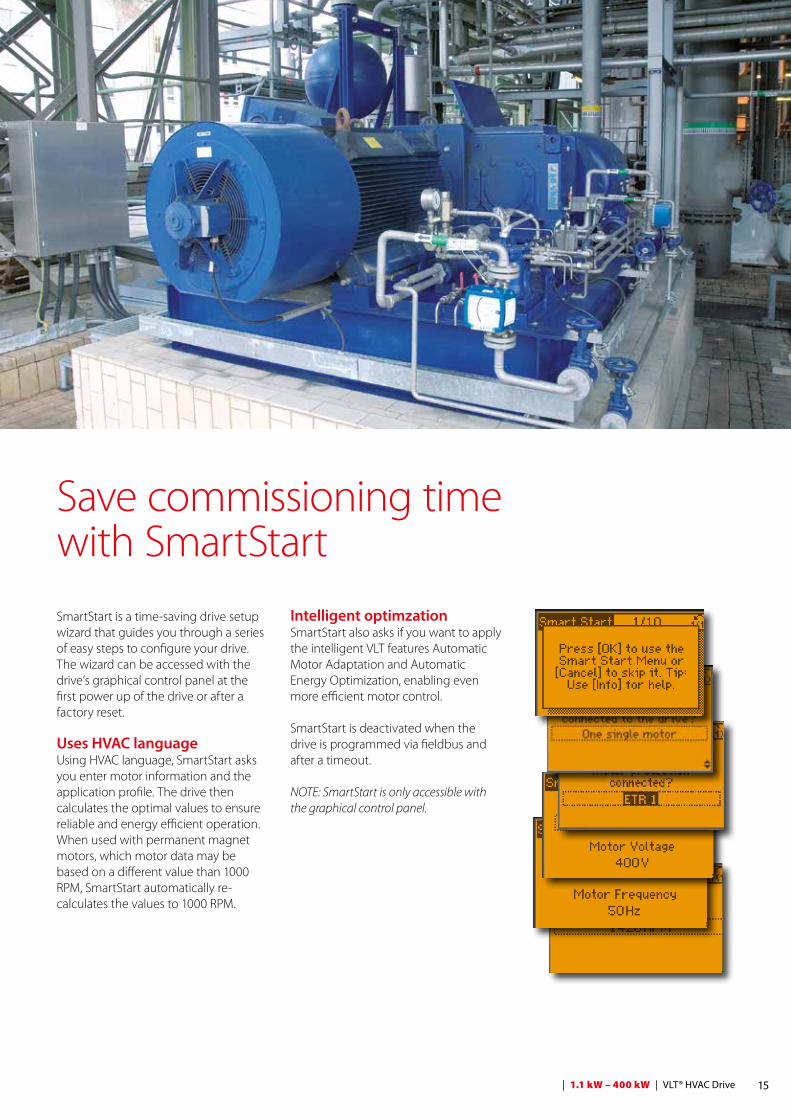
Intelligent optimzation SmartStart also asks if you want to apply the intelligent VLT features Automatic Motor Adaptation and Automatic Energy Optimization, enabling even more efficient motor control.
SmartStart is deactivated when the drive is programmed via fieldbus and after a timeout.
NOTE: SmartStart is only accessible with the graphical control panel.
Save commissioning time with SmartStart
SmartStart is a time-saving drive setup wizard that guides you through a series of easy steps to configure your drive. The wizard can be accessed with the drive’s graphical control panel at the first power up of the drive or after a factory reset.
Uses HVAC languageUsing HVAC language, SmartStart asks you enter motor information and the application profile. The drive then calculates the optimal values to ensure reliable and energy efficient operation. When used with permanent magnet motors, which motor data may be based on a different value than 1000 RPM, SmartStart automatically re-calculates the values to 1000 RPM.
15 | 1.1 kW – 400 kW | VLT® HVAC Drive
16 VLT® HVAC Drive | 1.1 kW – 400 kW |
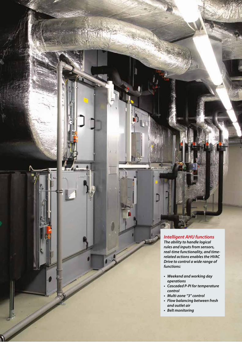
Intelligent AHU functionsThe ability to handle logical rules and inputs from sensors, real-time functionality, and time-related actions enables the HVAC Drive to control a wide range of functions:
• Weekend and working day operations
• Cascaded P-PI for temperature control
• Multi-zone “3” control• Flow balancing between fresh
and outlet air• Belt monitoring
Velocity to flow conversionThe VLT® HVAC Drive is able to convert velocity pressure sensor values into flow values. This provides operators with the opportunity to set the drive up to provide a fixed flow or fixed differential flow. Regardless of method, the advantages are the same, as energy consumption is optimised while improving comfort. An added benefit is that this built-in setting eliminates the need for a flow sensor.
Fire override modeThis safety feature prevents the drive from stopping to protect itself. Instead it will continue vital fan operation regardless of control signals, warnings or alarms.
Extend BMS capacityEasy integration into building management systems provides managers with detailed information about the current state of the infrastructure in the building. By integrating the drive into the building management network, all the I/O points in the drive are available as remote I/O to extend the capacity of the BMS.
For example: by installing room temperature sensors (PT 100/PT 1000) and monitoring them with the VLT® Sensor Input Card, the motor is protected from overheating in the bearings and windings. Monitoring of sensor temperature is either visible as a readout on the display or via fieldbus.
Resonance monitoringAvoid unwanted noise by setting the drive to avoid the frequency bands that cause fans to create resonances. Not only does this increase comfort, it also reduces wear on the equipment.
Stairwell pressurisationIf there is a fire, the VLT HVAC Drive will continue to control the motor, even beyond its standard shutoff parameters. By maintaining a higher level of air in the stairwells than in other parts of the building, fire escapes remain smoke free.
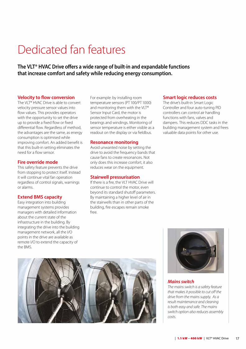
Dedicated fan featuresThe VLT® HVAC Drive offers a wide range of built-in and expandable functions that increase comfort and safety while reducing energy consumption.
Smart logic reduces costsThe drive’s built-in Smart Logic Controller and four auto-tuning PID controllers can control air handling functions with fans, valves and dampers. This reduces DDC tasks in the building management system and frees valuable data points for other use.
Mains switchThe mains switch is a safety feature that makes it possible to cut off the drive from the mains supply. As a result maintenance and cleaning is both easy and safe. The mains switch option also reduces assembly costs.
17 | 1.1 kW – 400 kW | VLT® HVAC Drive
Embedded pump controllerThe Pump Cascade Controller distributes operation hours evenly across all pumps. Wear and tear on individual pumps is therefore reduced to a minimum, extending their lifetime expectancy and reliability considerably.
Vital water supplyIf a pipe leaks or breaks, the HVAC Drive can reduce the motor speed to prevent overload, while continuing to supply water a lower speed.
Sleep modeIn situations with low or now flow, the drive enters sleep mode to conserve energy. When the pressure falls below the pre-defined setpoint, the drive starts automatically. Compared to continuous operation this method reduces energy costs and equipment wear and tear, extending the lifetime of the application.
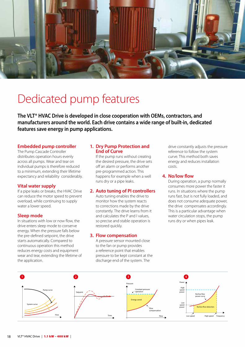
1. Dry Pump Protection and End of Curve
If the pump runs without creating the desired pressure, the drive sets off an alarm or performs another pre-programmed action. This happens for example when a well runs dry or a pipe leaks.
2. Auto tuning of PI controllers Auto tuning enables the drive to
monitor how the system reacts to corrections made by the drive constantly. The drive learns from it and calculates the P and I values, so precise and stable operation is restored quickly.
3. Flow compensation A pressure sensor mounted close
to the fan or pump provides a reference point that enables pressure to be kept constant at the discharge end of the system. The
Dedicated pump features The VLT® HVAC Drive is developed in close cooperation with OEMs, contractors, and manufacturers around the world. Each drive contains a wide range of built-in, dedicated features save energy in pump applications.
1 2 3 4
drive constantly adjusts the pressure reference to follow the system curve. This method both saves energy and reduces installation costs.
4. No/low flow During operation, a pump normally
consumes more power the faster it runs. In situations where the pump runs fast, but is not fully loaded, and does not consume adequate power, the drive compensates accordingly. This is a particular advantage when water circulation stops, the pump runs dry or when pipes leak.
18 VLT® HVAC Drive | 1.1 kW – 400 kW |

Optimize PM motor performanceDanfoss has refined its VVC+ algorithm and optimised it for permanent magnet motors. This improvement makesit possible for owners to benefit from the high motor efficiency of EC technology. After entering the relevant motor data, the drive automatically optimizes the performance of the application.
Free choice of technologyVLT® drives are equally efficient at controlling PM and asynchronous motors.
By providing vendors with the freedom to select the optimum combination of drive and motor, it is possible to offer the best possible system efficiency. This is a clear advantage compared to integrated systems, where it often is not possible to optimize the individual components.
Easy maintenanceComponent replacement as a result of wear and tear is not always possible without installing a complete new, integrated system. The EC+ concept answers this challenge by making service and maintenance easier, as only the affected component needs to be repaired/replaced in the event of malfunction.
Downtime is therefore reduced, and so are maintenance costs. These savings are the result of the fact that the EC+ concept is based on standardized components. All units can be shipped at short notice and installed with little effort.
Optimize system performance with EC+
EC motor with electronics being build into the fan impeller impacts the airflow through the impeller.
Values related to ILK report
Values related to ILK report
Plugfan with optimal and efficient airflow through the fan impeller.In combination with VSD and high efficient foot mounted permanent magnet motor.
η Drive= 89% | η Fan= 71% | η System= 63%
PM/EC motor + VSD + direct drive fan
η Drive= 89% | η Fan= 66% | η System= 59%
EC motor + integrated electronics + fan
Danfoss EC+ concept gives manufacturers of ventilation units the freedom to select their preferred motor from any supplier and control it with a VLT®
65
60
55
50
45
40 0 % 10 % 20 % 30 % 40 % 50 % 60 % 70 % 80 % 90 % 100 % 110 %
Syst
em e
�ec
ienc
y [%
]
Relative partial load [%]
EC+/PM (IE4)
EC+/PM (IE4)EC (IE4)IM (IE3)IM (IE2)
Tests at the Institute of Air Handling and Refrigeration (ILK) in Dresden have shown that the EC+ concept lowers the losses in ventilator systems by up to 10 %, compared to conventional EC technology. This is the result of 3-5 % higher system efficiency, depending on the nominal power size and the partial load.
Highest efficiency with EC+
19 | 1.1 kW – 400 kW | VLT® HVAC Drive

1. EnclosureThe drive meets requirements for enclosure class IP 20/Chassis. IP 21/Type 1, IP 54/Type 12, IP 55/Type 12 or IP 66/Type 4X.
2. EMC and Network effects All versions of VLT® HVAC Drive comply as standard with EMC limits B, A1 or A2 according to the EN 55011 norm. The standard integrated DC coils ensure low harmonic load on the network according to EN 61000-3-12 and increase the lifetime of the DC link capacitors.
3. Protective coating The electronic components are, as standard, coated as per IEC 60721-3-3, class 3C2. For harsh and aggressive environments, coating as per IEC 60721-3-3, class 3C3 is available.
4. Removable fan Like most of the elements, the fan can be quickly removed and remounted for easy cleaning.
5. Control terminals Double-stack, spring-loaded cage clamps enhance reliability and facilitate easy commissioning and service.
6. Fieldbus option See complete list of available fieldbus options on page 34.
Delivered fully assembled and tested to meet your specific requirements
Modular simplicity
7. I/O extensionsA wide range of I/O options are available either factory-mounted or as retrofit.
8. Display option Danfoss VLT Drives’ removable Local Control Panel is available with a variety of language packs: East European, West European, Asian and North American.
English and German are available in all drives.
Alternatively the drive can be commissioned via the built-in USB/RS485 connection or a fieldbus from with VLT® Motion Control Tool MCT 10 setup software.
8
6
7
4
3
1
2
9
5
20 VLT® HVAC Drive | 1.1 kW – 400 kW |
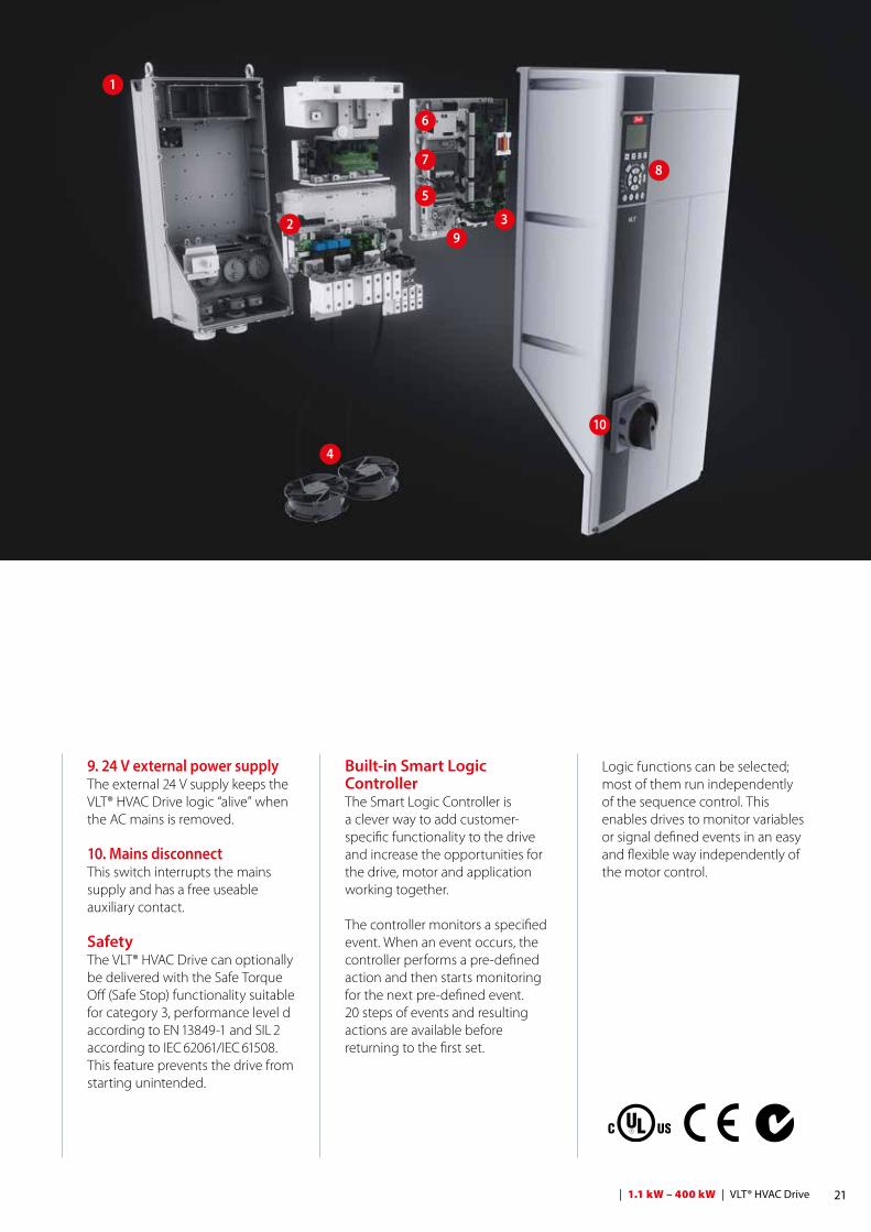
Logic functions can be selected; most of them run independently of the sequence control. This enables drives to monitor variables or signal defined events in an easy and flexible way independently of the motor control.
9. 24 V external power supply The external 24 V supply keeps the VLT® HVAC Drive logic “alive” when the AC mains is removed.
10. Mains disconnectThis switch interrupts the mains supply and has a free useable auxiliary contact.
SafetyThe VLT® HVAC Drive can optionally be delivered with the Safe Torque Off (Safe Stop) functionality suitable for category 3, performance level d according to EN 13849-1 and SIL 2 according to IEC 62061/IEC 61508. This feature prevents the drive from starting unintended.
Built-in Smart Logic ControllerThe Smart Logic Controller is a clever way to add customer-specific functionality to the drive and increase the opportunities for the drive, motor and application working together.
The controller monitors a specified event. When an event occurs, the controller performs a pre-defined action and then starts monitoring for the next pre-defined event. 20 steps of events and resulting actions are available before returning to the first set.
8
6
7
4
3
1
29
10
5
21 | 1.1 kW – 400 kW | VLT® HVAC Drive

Minimize energy costs As energy becomes increasingly expensive, variable speed control of electrical motors has proven to be one of the most effective cost-reducing measures available.
For example, by reducing the average speed of the motor from 100% to 80% in for example pumps or fans, 50% energy is saved. Reducing the average speed by 50% increases the savings to 80%.
The big pictureAn investment that paysIncrease application performance and streamline processes with energy efficient, adaptive motor control. Combine reliable, high performing solutions from a single supplier to reduce the lifetime costs of your applications.
Automatic Energy Optimization ensures that the motor voltage adapts automatically to changing loads. This provides an efficiency boost of up to 5-15%, reducing the cost of ownership substantially.
On the following pages we help you select the optimal VLT® for applications from 1.1 and 400 kW. For larger drives, please consult the
selection guide for Danfoss VLT® High Power Drives.
Reduce total cost of ownershipSeen over its lifetime, the initial cost of a drive only amounts to 10% of the total cost of ownership; the remaining 90% cover energy consumption, service and maintenance.
During setup Automatic Motor Adaptation (AMA) and later during operation Automatic Energy Optimization (AEO) ensure that the drive is perfectly adapted to the attached motor and changing loads.
Once in operation VLT® drives serve reliably for their entire lifetime. Only requiring minimal maintenance, the VLT® HVAC Drives provide a fast return on investment and ultimately a competitive cost of ownership.
Time
Initial cost
Disposal costs
Cost
Energy cost
Operation and maintenance costs
22 VLT® HVAC Drive | 1.1 kW – 400 kW |
23 | 1.1 kW – 400 kW | VLT® HVAC Drive
24 VLT® HVAC Drive | 1.1 kW – 400 kW |
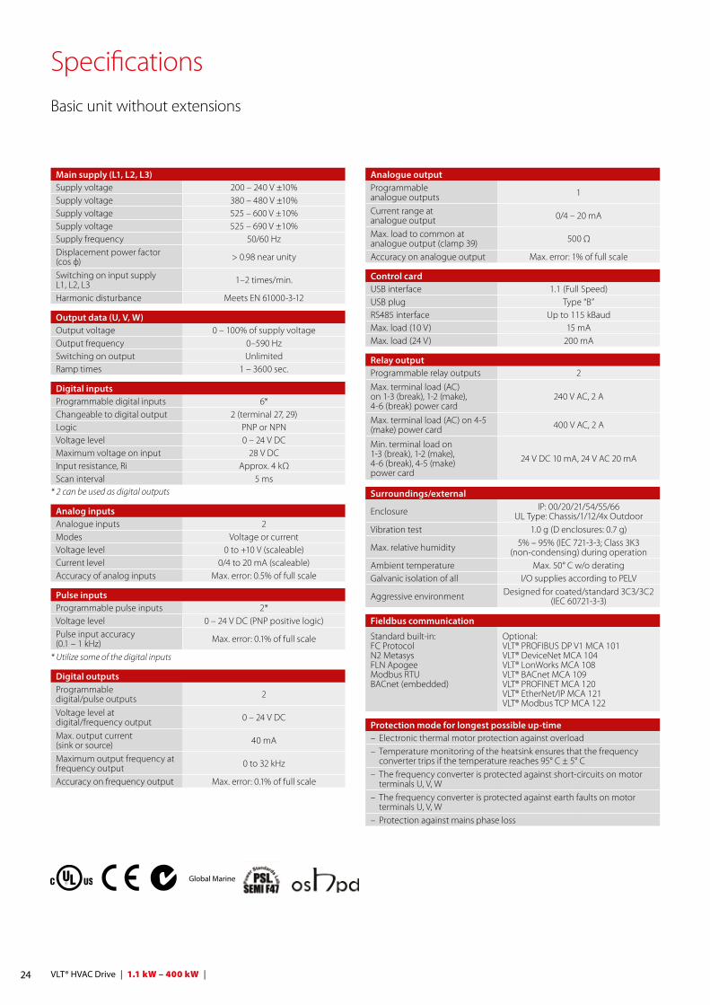
SpecificationsBasic unit without extensions
Global Marine
Main supply (L1, L2, L3)Supply voltage 200 – 240 V ±10%Supply voltage 380 – 480 V ±10%Supply voltage 525 – 600 V ±10%Supply voltage 525 – 690 V ±10%Supply frequency 50/60 HzDisplacement power factor(cos ф) > 0.98 near unity
Switching on input supply L1, L2, L3 1–2 times/min.
Harmonic disturbance Meets EN 61000-3-12
Output data (U, V, W)Output voltage 0 – 100% of supply voltageOutput frequency 0–590 HzSwitching on output UnlimitedRamp times 1 – 3600 sec.
Digital inputsProgrammable digital inputs 6*Changeable to digital output 2 (terminal 27, 29)Logic PNP or NPNVoltage level 0 – 24 V DCMaximum voltage on input 28 V DCInput resistance, Ri Approx. 4 kΩScan interval 5 ms
* 2 can be used as digital outputs
Analog inputsAnalogue inputs 2Modes Voltage or currentVoltage level 0 to +10 V (scaleable)Current level 0/4 to 20 mA (scaleable)Accuracy of analog inputs Max. error: 0.5% of full scale
Pulse inputsProgrammable pulse inputs 2*Voltage level 0 – 24 V DC (PNP positive logic)Pulse input accuracy (0.1 – 1 kHz) Max. error: 0.1% of full scale
* Utilize some of the digital inputs
Digital outputsProgrammable digital/pulse outputs 2
Voltage level at digital/frequency output 0 – 24 V DC
Max. output current (sink or source) 40 mA
Maximum output frequency at frequency output 0 to 32 kHz
Accuracy on frequency output Max. error: 0.1% of full scale
Analogue outputProgrammable analogue outputs 1
Current range at analogue output 0/4 – 20 mA
Max. load to common at analogue output (clamp 39) 500 Ω
Accuracy on analogue output Max. error: 1% of full scale
Control cardUSB interface 1.1 (Full Speed)USB plug Type “B”RS485 interface Up to 115 kBaudMax. load (10 V) 15 mAMax. load (24 V) 200 mA
Relay outputProgrammable relay outputs 2
Max. terminal load (AC) on 1-3 (break), 1-2 (make), 4-6 (break) power card
240 V AC, 2 A
Max. terminal load (AC) on 4-5 (make) power card 400 V AC, 2 A
Min. terminal load on 1-3 (break), 1-2 (make), 4-6 (break), 4-5 (make) power card
24 V DC 10 mA, 24 V AC 20 mA
Surroundings/external
Enclosure IP: 00/20/21/54/55/66UL Type: Chassis/1/12/4x Outdoor
Vibration test 1.0 g (D enclosures: 0.7 g)
Max. relative humidity 5% – 95% (IEC 721-3-3; Class 3K3 (non-condensing) during operation
Ambient temperature Max. 50° C w/o deratingGalvanic isolation of all I/O supplies according to PELV
Aggressive environment Designed for coated/standard 3C3/3C2 (IEC 60721-3-3)
Fieldbus communication
Standard built-in:FC Protocol N2 MetasysFLN ApogeeModbus RTUBACnet (embedded)
Optional:VLT® PROFIBUS DP V1 MCA 101VLT® DeviceNet MCA 104VLT® LonWorks MCA 108VLT® BACnet MCA 109VLT® PROFINET MCA 120VLT® EtherNet/IP MCA 121 VLT® Modbus TCP MCA 122
Protection mode for longest possible up-time– Electronic thermal motor protection against overload– Temperature monitoring of the heatsink ensures that the frequency
converter trips if the temperature reaches 95° C ± 5° C– The frequency converter is protected against short-circuits on motor
terminals U, V, W– The frequency converter is protected against earth faults on motor
terminals U, V, W– Protection against mains phase loss
25 | 1.1 kW – 400 kW | VLT® HVAC Drive
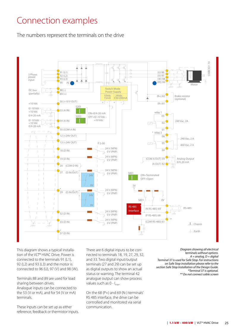
Connection examplesThe numbers represent the terminals on the drive
This diagram shows a typical installa-tion of the VLT® HVAC Drive. Power is connected to the terminals 91 (L1), 92 (L2) and 93 (L3) and the motor is connected to 96 (U), 97 (V) and 98 (W).
Terminals 88 and 89 are used for load sharing between drives.Analogue inputs can be connected to the 53 (V or mA), and for 54 (V or mA) terminals.
These inputs can be set up as either reference, feedback or thermistor inputs.
There are 6 digital inputs to be con-nected to terminals 18, 19, 27, 29, 32, and 33. Two digital input/output terminals (27 and 29) can be set up as digital outputs to show an actual status or warning. The terminal 42 analogue output can show process values such as 0 - Imax.
On the 68 (P+) and 69 (N-) terminals’RS 485 interface, the drive can be controlled and monitored via serial communication.
3 Phasepowerinput
DC bus(partially)
Switch ModePower Supply
Motor
Analog Output
Interface
relay 1
* relay 2
ON=TerminatedOFF=Open
Brake resistor (optional)
130B
C931
.10
91 (L1)92 (L2)93 (L3)
PE
88 (-)89 (+)
50 (+10 V OUT)
53 (A IN)
54 (A IN)
55 (COM A IN)0/4-20 mA
12 (+24V OUT)
13 (+24V OUT)
37 (D IN)
18 (D IN)
20 (COM D IN)
10Vdc15mA 130/200mA
+ - + -
(U) 96(V) 97(W) 98(PE) 99
(COM A OUT) 39
(A OUT) 42
(P RS-485) 68
(N RS-485) 69
(COM RS-485) 61
0V
5V
S801
0/4-20 mA
RS-485RS-485
03
+10 Vdc0/-10 Vdc -
+10 Vdc
+10 Vdc0/4-20 mA
0/-10 Vdc -
240 Vac, 2A
24Vdc
02
01
05
04
06240 Vac, 2 A
24 V (NPN) 0 V (PNP)
0 V (PNP)24 V (NPN)
19 (D IN)
24 V (NPN) 0 V (PNP)27
24V
0V
(D IN/OUT)
0 V (PNP)24 V (NPN)
(D IN/OUT)
0V
24V29
24 V (NPN) 0 V (PNP)
0 V (PNP)24 V (NPN)
33 (D IN)
32 (D IN)
12
ON
S201
ON2
1S202ON=0/4-20 mAOFF=0/-10 Vdc - +10 Vdc
95
400 Vac, 2 AP 5-00
21 O
N
S801
(R+) 82
(R-) 81
*
*
: Chassis
: Earth
**
Diagram showing all electrical terminals without options.
A = analog, D = digitalTerminal 37 is used for Safe Stop. For instructions
on Safe Stop installation please refer to the section Safe Stop Installation of the Design Guide.
*Terminal 37 is optional.** Do not connect cable screen

26 VLT® HVAC Drive | 1.1 kW – 400 kW |
VLT® HVAC Drive 200-240 V AC
* (A2, A3, B3, B4, C3 and C4 may be converted to IP 21/Type 1 using a conversion kit. (Please see also items mechanical mounting in Operating Instructions and IP 21/ Type 1 enclosure kit in the Design Guide.)
EnclosureIP 20 (IP 21*)/Chassis (Type 1) B3 B4 C3 C4
IP 21/Type 1, IP 55 + IP 66//Type 4X B1 B2 C1 C2P5K5 P7K5 P11K P15K P18K P22K P30K P37K P45K
Typical shaft output [kW] 5.5 7.5 11 15 18.5 22 30 37 45
Typical shaft output at 208 V [HP] 7.5 10 15 20 25 30 40 50 60
Output current
Continuous (3 x 200 – 240 V) [A] 24.2 30.8 46.2 59.4 74.8 88 115 143 170
Intermittent (3 x 200 – 240 V) [A] 26.6 33.9 50.8 65.3 82.3 96.8 127 157 187
Output power
Continuous (208 V AC) [kVA] 8.7 11.1 16.6 21.4 26.9 31.7 41.4 51.5 61.2
Rated input current
Continuous (3 x 200 – 240 V) [A] 22 28 42 54 68 80 104 130 154
Intermittent (3 x 200 – 240 V) [A] 24.2 30.8 46.2 59.4 74.8 88 114 143 169
Estimated power loss at rated max. load [W] 269 310 447 602 737 845 1140 1353 1636
Efficiency 0.96 0.97
Max. cable size Mains, motor, brake
[mm2]([AWG]) 10 (7) 35 (2) 50 (1)
(B4 = 35 (2))150 (300
MCM)150 (300
MCM)
Max. cable size mainsWith mains disconnect switch included
[mm2]([AWG]) 16 (6) 35 (2) 50, 35, 35 (1, 2, 2)
95, 70, 70
(3/0, 2/0, 2/0)
185, 150, 120(350
MCM,300
MCM, 4/0)
Max. pre-fuses [A] 63 80 125 160 200 250
Weight
IP 20 [kg] 12 23.5 35 50
IP 21, IP 55, IP 66 [kg] 23 27 45 65
EnclosureIP 20 (IP 21*)/Chassis (Type 1) A2 A3
IP 55 + IP 66/ Type 4X A4 + A5 A5P1K1 P1K5 P2K2 P3K0 P3K7
Typical shaft output [kW] 1.1 1.5 2.2 3 3.7
Typical shaft output at 208 V [HP] 1.5 2.0 2.9 4.0 4.9
Output current
Continuous (3 x 200 – 240 V) [A] 6.6 7.5 10.6 12.5 16.7
Intermittent (3 x 200 – 240 V) [A] 7.3 8.3 11.7 13.8 18.4
Output power
Continuous (208 V AC) [kVA] 2.38 2.70 3.82 4.50 6.00
Rated input current
Continuous (3 x 200 – 240 V) [A] 5.9 6.8 9.5 11.3 15.0
Intermittent (3 x 200 – 240 V) [A] 6.5 7.5 10.5 12.4 16.5
Estimated power loss at rated max. load [W] 63 82 116 155 185
Efficiency 0.96
Max. cable sizeMains, motor, brake
[mm2]([AWG]) 4 (12)
Max. pre-fuses [A] 20 32
Weight
IP 20 [kg] 4.9 6.6
IP 21 [kg] 5.5 7.5
IP 55, IP 66 [kg] 9.7 (A4)/13.5 (A2 + A5) 13.5

27 | 1.1 kW – 400 kW | VLT® HVAC Drive
VLT® HVAC Drive 380 – 480 V AC
* (A2, A3, B3, B4, C3 and C4 may be converted to IP 21 using a conversion kit. Please contact Danfoss. (Please see also items Mechanical mounting in Operating Instructions and IP 21/ Type 1 Enclosure kit in the Design Guide.))
1) With brake and load sharing 95 (4/0)
EnclosureIP 20 (IP 21*)/Chassis (Type 1) A2 A3
IP 55 + IP 66 /Type 4X A4 + A5 A5P1K1 P1K5 P2K2 P3K0 P4K0 P5K5 P7K5
Typical shaft output [kW] 1.1 1.5 2.2 3 4 5.5 7.5
Typical shaft output at 460 V [HP] 1.5 2.0 2.9 4.0 5.0 7.5 10
Output current
Continuous (3 x 380 – 440 V) [A] 3 4.1 5.6 7.2 10 13 16
Intermittent (3 x 380 – 440 V) [A] 3.3 4.5 6.2 7.9 11 14.3 17.6
Continuous (3 x 441 – 480 V) [A] 2.7 3.4 4.8 6.3 8.2 11 14.5
Intermittent (3 x 441 – 480 V) [A] 3.0 3.7 5.3 6.9 9.0 12.1 15.4
Output power
Continuous (400 V AC) [kVA] 2.1 2.8 3.9 5.0 6.9 9.0 11.0
Continuous (460 V AC) [kVA] 2.4 2.7 3.8 5.0 6.5 8.8 11.6
Rated input current
Continuous (3 x 380 – 440 V) [A] 2.7 3.7 5.0 6.5 9.0 11.7 14.4
Intermittent (3 x 380 – 440 V) [A] 3.0 4.1 5.5 7.2 9.9 12.9 15.8
Continuous (3 x 441 – 480 V) [A] 2.7 3.1 4.3 5.7 7.4 9.9 13.0
Intermittent (3 x 441 – 480 V) [A] 3.0 3.4 4.7 6.3 8.1 10.9 14.3
Estimated power loss at rated max. load [W] 58 62 88 116 124 187 255
Efficiency 0.96 0.97
Max. cable size(Mains, motor, brake)
[mm2]([AWG]) 4 (12)
Max. pre-fuses [A] 10 20 32
Weight
IP 20 [kg] 4.8 4.9 6.6
IP 55, IP 66 [kg] 9.7 (A4)/13.5 (A2 + A5) 14.2
EnclosureIP 20 (IP 21*)/Chassis (Type 1) B3 B4 C3 C4
IP 21/Type 1, IP 55 + IP 66/Type 4X B1 B2 C1 C2P11K P15K P18K P22K P30K P37K P45K P55K P75K P90K
Typical shaft output [kW] 11 15 18.5 22 30 37 45 55 75 90
Typical shaft output at 460 V [HP] 15 20 25 30 40 50 60 75 100 125
Output current
Continuous (3 x 380 – 439 V) [A] 24 32 37.5 44 61 73 90 106 147 177
Intermittent (3 x 380 – 439 V) [A] 26.4 35.2 41.3 48.4 67.1 80.3 99 117 162 195
Continuous (3 x 440 – 480 V) [A] 21 27 34 40 52 65 80 105 130 160
Intermittent (3 x 440 – 480 V) [A] 23.1 29.7 37.4 44 61.6 71.5 88 116 143 176
Output power
Continuous (400 V AC) [kVA] 16.6 22.2 26 30.5 42.3 50.6 62.4 73.4 102 123
Continuous (460 V AC) [kVA] 16.7 21.5 27.1 31.9 41.4 51.8 63.7 83.7 104 128
Rated input current
Continuous (3 x 380 – 439 V) [A] 22 29 34 40 55 66 82 96 133 161
Intermittent (3 x 380 – 439 V) [A] 24.2 31.9 37.4 44 60.5 72.6 90.2 106 146 177
Continuous (3 x 440 – 480 V) [A] 19 25 31 36 47 59 73 95 118 145
Intermittent (3 x 440 – 480 V) [A] 20.9 27.5 34.1 39.6 51.7 64.9 80.3 105 130 160
Estimated power loss at rated max. load [W] 278 392 465 525 698 739 843 1083 1384 1474
Efficiency 0.98 0.99
Max. cable size Mains, motor, brake
[mm2]([AWG]) 10 (8) 35 (2) 50 (1)
(B4 = 35 (2)) 95 (4/0) 95 (4/0)
Max. cable size mainsWith mains disconnect switch included
[mm2]([AWG]) 16, 10, 10 (6, 8, 8) 50, 35, 35
(1, 2, 2)
95, 70, 70
(3/0, 2/0, 2/0)
185, 150, 120(350
MCM, 300
MCM, 4/0)
Max. pre-fuses [A] 63 63 63 63 80 100 125 160 250 250
Weight
IP 20 [kg] 12 12 12 23.5 23.5 23.5 35 35 50 50
IP 21, IP 55, IP 66 [kg] 23 23 23 27 27 45 45 45 65 65
28 VLT® HVAC Drive | 1.1 kW – 400 kW |
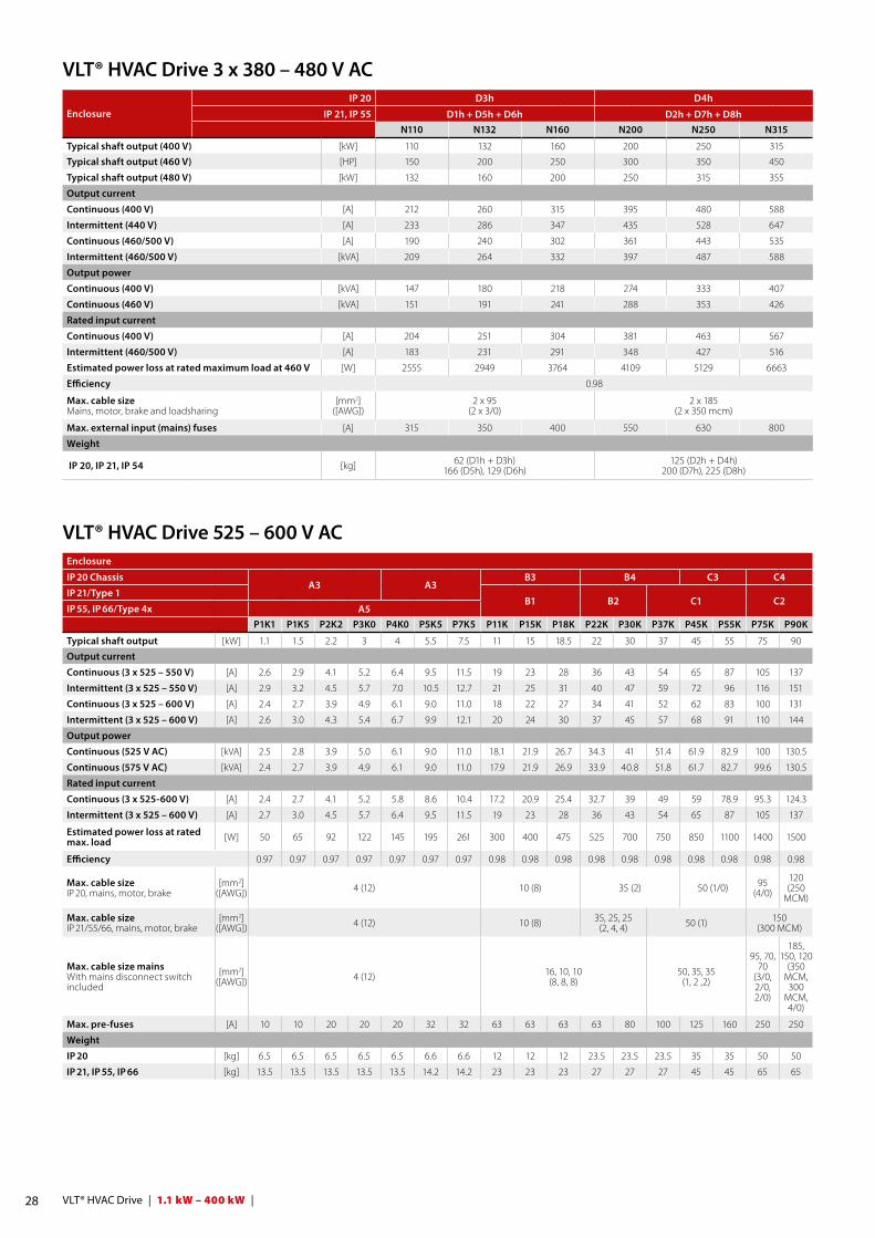
VLT® HVAC Drive 3 x 380 – 480 V AC
VLT® HVAC Drive 525 – 600 V AC
EnclosureIP 20 D3h D4h
IP 21, IP 55 D1h + D5h + D6h D2h + D7h + D8hN110 N132 N160 N200 N250 N315
Typical shaft output (400 V) [kW] 110 132 160 200 250 315
Typical shaft output (460 V) [HP] 150 200 250 300 350 450
Typical shaft output (480 V) [kW] 132 160 200 250 315 355
Output current
Continuous (400 V) [A] 212 260 315 395 480 588
Intermittent (440 V) [A] 233 286 347 435 528 647
Continuous (460/500 V) [A] 190 240 302 361 443 535
Intermittent (460/500 V) [kVA] 209 264 332 397 487 588
Output power
Continuous (400 V) [kVA] 147 180 218 274 333 407
Continuous (460 V) [kVA] 151 191 241 288 353 426
Rated input current
Continuous (400 V) [A] 204 251 304 381 463 567
Intermittent (460/500 V) [A] 183 231 291 348 427 516
Estimated power loss at rated maximum load at 460 V [W] 2555 2949 3764 4109 5129 6663
Efficiency 0.98
Max. cable size Mains, motor, brake and loadsharing
[mm2]([AWG])
2 x 95(2 x 3/0)
2 x 185 (2 x 350 mcm)
Max. external input (mains) fuses [A] 315 350 400 550 630 800
Weight
IP 20, IP 21, IP 54 [kg] 62 (D1h + D3h)166 (D5h), 129 (D6h)
125 (D2h + D4h)200 (D7h), 225 (D8h)
Enclosure
IP 20 ChassisA3 A3
B3 B4 C3 C4
IP 21/Type 1B1 B2 C1 C2
IP 55, IP 66/Type 4x A5P1K1 P1K5 P2K2 P3K0 P4K0 P5K5 P7K5 P11K P15K P18K P22K P30K P37K P45K P55K P75K P90K
Typical shaft output [kW] 1.1 1.5 2.2 3 4 5.5 7.5 11 15 18.5 22 30 37 45 55 75 90
Output current
Continuous (3 x 525 – 550 V) [A] 2.6 2.9 4.1 5.2 6.4 9.5 11.5 19 23 28 36 43 54 65 87 105 137
Intermittent (3 x 525 – 550 V) [A] 2.9 3.2 4.5 5.7 7.0 10.5 12.7 21 25 31 40 47 59 72 96 116 151
Continuous (3 x 525 – 600 V) [A] 2.4 2.7 3.9 4.9 6.1 9.0 11.0 18 22 27 34 41 52 62 83 100 131
Intermittent (3 x 525 – 600 V) [A] 2.6 3.0 4.3 5.4 6.7 9.9 12.1 20 24 30 37 45 57 68 91 110 144
Output power
Continuous (525 V AC) [kVA] 2.5 2.8 3.9 5.0 6.1 9.0 11.0 18.1 21.9 26.7 34.3 41 51.4 61.9 82.9 100 130.5
Continuous (575 V AC) [kVA] 2.4 2.7 3.9 4.9 6.1 9.0 11.0 17.9 21.9 26.9 33.9 40.8 51.8 61.7 82.7 99.6 130.5
Rated input current
Continuous (3 x 525-600 V) [A] 2.4 2.7 4.1 5.2 5.8 8.6 10.4 17.2 20.9 25.4 32.7 39 49 59 78.9 95.3 124.3
Intermittent (3 x 525 – 600 V) [A] 2.7 3.0 4.5 5.7 6.4 9.5 11.5 19 23 28 36 43 54 65 87 105 137
Estimated power loss at rated max. load [W] 50 65 92 122 145 195 261 300 400 475 525 700 750 850 1100 1400 1500
Efficiency 0.97 0.97 0.97 0.97 0.97 0.97 0.97 0.98 0.98 0.98 0.98 0.98 0.98 0.98 0.98 0.98 0.98
Max. cable size IP 20, mains, motor, brake
[mm2]([AWG]) 4 (12) 10 (8) 35 (2) 50 (1/0) 95
(4/0)
120 (250
MCM)
Max. cable size IP 21/55/66, mains, motor, brake
[mm2]([AWG]) 4 (12) 10 (8) 35, 25, 25
(2, 4, 4) 50 (1) 150 (300 MCM)
Max. cable size mainsWith mains disconnect switch included
[mm2]([AWG]) 4 (12) 16, 10, 10
(8, 8, 8)50, 35, 35
(1, 2 ,2)
95, 70, 70
(3/0, 2/0, 2/0)
185, 150, 120
(350 MCM, 300
MCM, 4/0)
Max. pre-fuses [A] 10 10 20 20 20 32 32 63 63 63 63 80 100 125 160 250 250
Weight
IP 20 [kg] 6.5 6.5 6.5 6.5 6.5 6.6 6.6 12 12 12 23.5 23.5 23.5 35 35 50 50
IP 21, IP 55, IP 66 [kg] 13.5 13.5 13.5 13.5 13.5 14.2 14.2 23 23 23 27 27 27 45 45 65 65

29 | 1.1 kW – 400 kW | VLT® HVAC Drive
VLT® HVAC Drive 3 x 525-690 V AC
VLT® HVAC Drive 3 x 525-690 V AC
EnclosureIP 20 A3 B4 C3 D3h
IP 21/IP 55 B2 C2P1K1 P1K5 P2K2 P3K0 P4K0 P5K5 P7K5 P11K P15K P18K5 P22K P30K P37K P45K P55K P75K P90K
Typical shaft output (690 V) [kW] 1.1 1.5 2.2 3 4 5.5 7.5 11 15 18.5 22 30 37 45 55 75 90
Output current (High overload 110% for 1 min.)
Continuous (3 x 525-550 V) [A] 2.1 2.7 3.9 4.9 6.1 9 11 14 19 23 28 36 43 54 65 87 105
Intermittent (3 x 525-550 V) [A] 3.4 4.3 6.2 7.8 9.8 14.4 17.6 22.4 20.9 25.3 30.8 39.6 47.3 59.4 71.5 95.7 115.5
Continuous kVA (3 x 551-690 V) [A] 1.6 2.2 3.2 4.5 5.5 7.5 10 13 18 22 27 34 41 52 62 83 100
Intermittent kVA (3 x 551-690 V) [A] 2.6 3.5 5.1 7.2 8.8 12 16 20.8 19.8 24.2 29.7 37.4 45.1 57.2 68.2 91.3 110
Output power
Continuous (550 V) (A3 525 V) [kVA] 1.9 2.5 3.5 4.5 5.5 8.2 10 13.3 18.1 21.9 26.7 34.3 41.0 51.4 61.9 82.9 100
Continuous (690 V) [kVA] 1.9 2.6 3.8 5.4 6.6 9 12 15.5 21.5 26.3 32.3 40.6 49.0 62.1 74.1 99.2 119.5
Rated input current
Continuous (3 x 525-550 V) [A] 1.9 2.4 3.5 4.4 5.5 8 10 15 19.5 24 29 36 49 59 71 87 99
Intermittent (3 x 525-550 V) [A] 3 3.9 5.6 7.1 8.8 13 16 23.2 21.5 26.4 31.9 39.6 53.9 64.9 78.1 95.7 108.9
Continuous kVA (3 x 551-690 V) [A] 1.4 2 2.9 4 4.9 6.7 9 14.5 19.5 24 29 36 48 58 70 86 94.3
Intermittent kVA (3 x 551-690 V) [A] 2.3 3.2 4.6 6.5 7.9 10.8 14.4 23.2 21.5 26.4 31.9 39.6 52.8 63.8 77 94.6 112.7
Estimated power loss at rated maximum load [W] 44 60 88 120 160 220 300 150 220 300 370 440 740 900 1100 1500 1800
Efficiency 0.96 0.98
Max. cable cross section Mains, motor, brake and load sharing
[mm2]([AWG]) 4 (12) 35 (2)
Max. external input (mains) fuses [A] – 63 80 100 125 160 –
Weight
IP 20 [kg] 6.6 21.5 (B4) 35 (C3) 62 (D3h)
IP 21, IP 55 [kg] – 27 (B2) 65 (C2) – 62 (D3h)
EnclosureIP 20 D3h D4h
IP 21, IP 55 D1h + D5h + D6h D2h + D7h + D8hN75K N90K N110 N132 N160 N200 N250 N315 N400
Typical shaft output (525 V) [kW] 55 75 90 110 132 160 200 250 315
Typical shaft output (575 V) [HP] 75 100 125 150 200 250 300 350 400
Typical shaft output (690 V) [kW] 75 90 110 132 160 200 250 315 400
Output current
Continuous (550 V) [A] 90 113 137 162 201 253 303 360 418
Intermittent (550 V) [A] 99 124 151 178 221 278 333 396 460
Continuous (575/690 V) [A] 86 108 131 155 192 242 290 344 400
Intermittent (575/690 V) [kVA] 95 119 144 171 211 266 319 378 440
Output power
Continuous (525 V) [kVA] 86 108 131 154 191 241 289 343 398
Continuous (575 V) [kVA] 86 108 130 154 191 241 289 343 398
Continuous (690 V) [kVA] 103 129 157 185 229 289 347 411 478
Rated input current
Continuous (550 V) [A] 89 110 130 158 198 245 299 355 408
Continuous (575 V) [A] 85 106 124 151 189 234 286 339 390
Continuous (690 V) [A] 87 109 128 155 197 240 296 352 400
Estimated power loss at 525/575 V [W] 1162 1428 1739 2099 2646 3071 3719 4460 5023
Estimated power loss at 690 V [W] 1204 1477 1796 2165 2738 3172 3848 4610 5150
Efficiency 0.98
Max. cable size Mains, motor, brake and loadsharing
[mm2]([AWG])
2 x 95(2 x 3/0)
2 x 185 (2 x 350 mcm)
Max. external input (mains) fuses [A] 160 315 350 400 500 550
Weight
IP 20, IP 21, IP 54 [kg] 62 (D1h + D3h)166 (D5h), 129 (D6h)
125 (D2h + D4h)200 (D7h), 225 (D8h)
30 VLT® HVAC Drive | 1.1 kW – 400 kW |
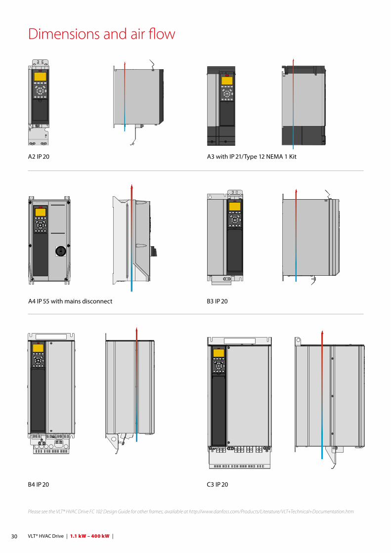
Dimensions and air flow
Please see the VLT® HVAC Drive FC 102 Design Guide for other frames, available at http://www.danfoss.com/Products/Literature/VLT+Technical+Documentation.htm
A2 IP 20
B3 IP 20
C3 IP 20
A3 with IP 21/Type 12 NEMA 1 Kit
A4 IP 55 with mains disconnect
B4 IP 20
31 | 1.1 kW – 400 kW | VLT® HVAC Drive
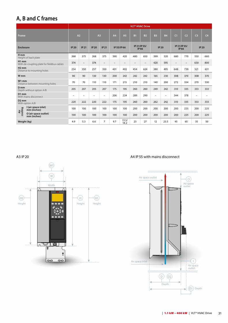
A, B and C frames
A4 IP 55 with mains disconnect
W
W1
H1H
O
I
H2
HeightHeight
Air space outlet
Air space outlet
Height
Width
A3 IP 20
D D2
D1Depth
Depth
Air space outlet
Air space inlet
VLT® HVAC Drive
Frame A2 A3 A4 A5 B1 B2 B3 B4 C1 C2 C3 C4
Enclosure IP 20 IP 21 IP 20 IP 21 IP 55/IP 66 IP 21/IP 55/IP 66 IP 20 IP 21/IP 55/
IP 66 IP 20
H mmHeight of back plate 268 375 268 375 390 420 480 650 399 520 680 770 550 660
H1 mm With de-coupling plate for fieldbus cables 374 – 374 – – – – – 420 595 – – 630 800
H2 mm Distance to mounting holes 254 350 257 350 401 402 454 624 380 495 648 739 521 631
W mm 90 90 130 130 200 242 242 242 165 230 308 370 308 370
W1 mmDistance between mounting holes 70 70 110 110 171 215 210 210 140 200 272 334 270 330
D mmDepth without option A/B 205 207 205 207 175 195 260 260 249 242 310 335 333 333
D1 mmWith mains disconnect – – – – 206 224 289 290 – – 344 378 – –
D2 mmWith option A/B 220 222 220 222 175 195 260 260 262 242 310 335 333 333
Air
co
olin
g I (air space inlet)mm (inches) 100 100 100 100 100 100 200 200 200 200 200 225 200 225
O (air space outlet)mm (inches) 100 100 100 100 100 100 200 200 200 200 200 225 200 225
Weight (kg) 4.9 5.3 6.6 7 9.7 13.5/14.2 23 27 12 23.5 45 65 35 50
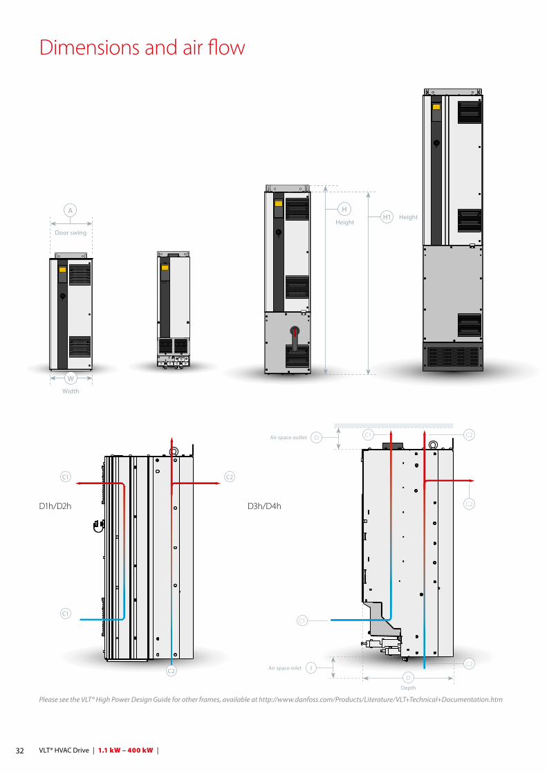
D1h/D2h D3h/D4h
OAir space outlet
C1
D
Depth
IAir space inlet
C2C1
C2
C2
C2
C2
C1
C1
Dimensions and air flow
W
A
Door swing
Width
Please see the VLT® High Power Design Guide for other frames, available at http://www.danfoss.com/Products/Literature/VLT+Technical+Documentation.htm
HH1 Height
Height
32 VLT® HVAC Drive | 1.1 kW – 400 kW |
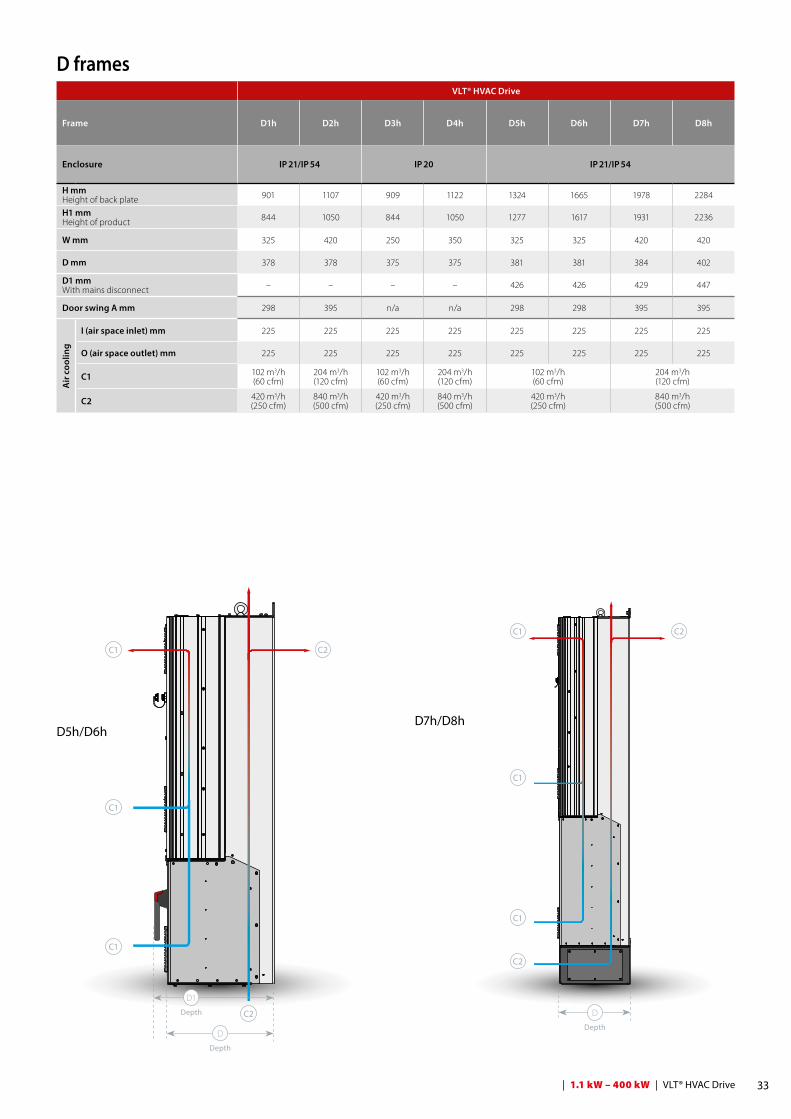
D5h/D6hD7h/D8h
C1
C1
C2
C2
C2
C1
C1
C1
C1
C2
D
D1
D
Depth
Depth
Depth
D framesVLT® HVAC Drive
Frame D1h D2h D3h D4h D5h D6h D7h D8h
Enclosure IP 21/IP 54 IP 20 IP 21/IP 54
H mmHeight of back plate 901 1107 909 1122 1324 1665 1978 2284
H1 mmHeight of product 844 1050 844 1050 1277 1617 1931 2236
W mm 325 420 250 350 325 325 420 420
D mm 378 378 375 375 381 381 384 402
D1 mmWith mains disconnect – – – – 426 426 429 447
Door swing A mm 298 395 n/a n/a 298 298 395 395
Air
coo
ling
I (air space inlet) mm 225 225 225 225 225 225 225 225
O (air space outlet) mm 225 225 225 225 225 225 225 225
C1 102 m3/h(60 cfm)
204 m3/h(120 cfm)
102 m3/h(60 cfm)
204 m3/h(120 cfm)
102 m3/h(60 cfm)
204 m3/h(120 cfm)
C2 420 m3/h(250 cfm)
840 m3/h(500 cfm)
420 m3/h(250 cfm)
840 m3/h(500 cfm)
420 m3/h(250 cfm)
840 m3/h(500 cfm)
33 | 1.1 kW – 400 kW | VLT® HVAC Drive
34 VLT® HVAC Drive | 1.1 kW – 400 kW |
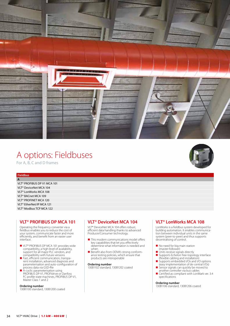
A options: FieldbusesFor A, B, C and D frames
VLT® PROFIBUS DP MCA 101Operating the frequency converter via a fieldbus enables you to reduce the cost of your system, communicate faster and more efficiently, and benefit from an easier user interface.
VLT® PROFIBUS DP MCA 101 provides wide compatibility, a high level of availability, support for all major PLC vendors, and compatibility with future versions
Fast, efficient communication, transpa-rent installation, advanced diagnosis and parameterisation and auto- configuration of process data via GSD-file
A-cyclic parameterisation using PROFIBUS DP-V1, PROFIdrive or Danfoss FC profile state machines, PROFIBUS DP-V1, Master Class 1 and 2
Ordering number 130B1100 standard, 130B1200 coated
VLT® LonWorks MCA 108LonWorks is a fieldbus system developed for building automation. It enables communica-tion between individual units in the same system (peer-to-peer) and thus supports decentralising of control.
No need for big main station (master-follower)
Units receive signals directly Supports Echelon free-topology interface
(flexible cabling and installation) Supports embedded I/Os and I/O options
(easy implementation of de-central I/Os) Sensor signals can quickly be moved to
another controller via bus cables Certified as compliant with LonMark ver. 3.4
specifications
Ordering number 130B1106 standard, 130B1206 coated
VLT® DeviceNet MCA 104VLT® DeviceNet MCA 104 offers robust, efficient data handling thanks to advanced Producer/Consumer technology.
This modern communications model offers key capabilities that let you effectively determine what information is needed and when
Benefit also from ODVA’s strong conform- ance testing policies, which ensure that products are interoperable
Ordering number 130B1102 standard, 130B1202 coated
FieldbusAVLT® PROFIBUS DP V1 MCA 101VLT® DeviceNet MCA 104VLT® LonWorks MCA 108VLT® BACnet MCA 109VLT® PROFINET MCA 120VLT® EtherNet/IP MCA 121VLT® Modbus TCP MCA 122

35 | 1.1 kW – 400 kW | VLT® HVAC Drive
VLT® BACnet MCA 109The open communications protocol for world-wide building automation. The BACnet protocol is an international proto-col that efficiently integrates all parts of build-ing automation equipment from the actuator level to the building management system.
Via the BACnet option it is possible to read all analogue and digital inputs and control all analogue and digital outputs of the VLT® HVAC Drive. All inputs and outputs can be operatedindependently of the drive’s functions and thus work as remote I/Os:
COV (Change of Value) Read/write Property Multiple Alarm/Warning handling
Ordering number 130B1144 standard, 130B1244 coated
VLT® PROFINET MCA 120VLT® PROFINET MCA 120 uniquely combines the highest performance with the highest degree of openness. The MCA120 gives the user access to the power of Ethernet. The op-tion is designed so that many of the features from the PROFIBUS MCA 101 can be reused, minimising user effort to migrate PROFINET, and securing the investment in PLC program.
Other features: Built-in web server for remote diagnosis and
reading out of basic drive parameters Support of DP-V1 Diagnostic allows easy,
fast and standardized handling of warning and fault information into the PLC, impro-ving bandwidth in the system
PROFINET encompasses a suite of messages and services for a variety of manufacturing automation applications, including control, configuration and information.
Ordering number 130B1135 standard, 130B1235 coated
VLT® EtherNet/IP MCA 121Ethernet is the future standard for communi-cation at the factory floor. The VLT® EtherNet/IP MCA 121 is based on the newest technol-ogy available for industrial use and handles even the most demanding requirements. EtherNet/IP extends commercial off-the-shelf Ethernet to the Common Industrial Protocol (CIP™) – the same upper-layer protocol and object model found in DeviceNet.
The VLT® MCA 121 offers advanced features as: Built-in high performance switch enabling
line-topology, and eliminating the need for external switches
Advanced switch and diagnoses functions Built-in web server E-mail client for service notification Unicast and Multicast communication
Ordering number 130B1119 standard, 130B1219 coated
VLT® Modbus TCP MCA 122Modbus TCP is the first industrial Ethernet based protocol for automation. The VLT® Mod-bus TCP MCA 122 connects to Modbus TCP based networks. It is able to handle connec-tion interval down to 5 ms in both directions, positioning it among the fastest performing
B options: Functional extensionsFor A, B, C and D frames
VLT® General Purpose I/O MCB 101This I/O option offers an extended number of control inputs and outputs:
3 digital inputs 0-24 V: Logic ‘0’ < 5 V; Logic ‘1’ > 10V
2 analogue inputs 0-10 V: Resolution 10 bit plus sign
2 digital outputs NPN/PNP push pull 1 analogue output 0/4-20 mA Spring loaded connection
Ordering number 130B1125 standard, 130B1212 coated
VLT® Relay Option MCB 105Makes it possible to extend relay functions with 3 additional relay outputs.
Max. terminal load: AC-1 Resistive load ........................... 240 V AC 2 A AC-15 Inductive
load @cos fi 0.4 ................................240 V AC 0.2 A DC-1 Resistive load ..............................24 V DC 1 A DC-13 Inductive
load @cos fi 0.4 .................................. 24 V DC 0.1 A
Min. terminal load: DC 5 V .......................................................................10 mA Max switch rate at rated
load/min. load ............................... 6 min-1/20 sec-1
Protects control cable connection Spring-loaded control wire connection
Ordering number 130B1110 standard, 130B1210 coated
VLT® Analog I/O Option MCB 109This analogue input/output option is easily fitted in the frequency converter for upgrad-ing to advanced performance and control using the additional in/outputs.This option also upgrades the frequency converter with a battery back-up supply for the frequency converter’s built-in clock. This provides stable use of all frequency converter clock functions as timed actions etc.
3 analogue inputs, each configurable as both voltage and temperature input
Connection of 0-10 V analogue signals as well as PT1000 and NI1000 temperature inputs
3 analogue outputs each configurable as 0-10 V outputs
Incl. back-up supply for the standard clock function in the frequency converter
Modbus TCP devices in the market. For master redundancy it features hot swapping between two masters.
Other features: Built-in web-server for remote diagnosis
and reading out basic drive parameters An e-mail notificator can be configured
for sending an e-mail message to one or several receivers, if certain warnings or alarms occurs, or has cleared again
Ordering number 130B1196 standard, 130B1296 coated
VLT® DeviceNet Converter MCA 194The VLT® DeviceNet Converter MCA 194 emulates VLT® 5000 commands in the VLT® AutomationDrive. This means that a VLT® 5000 can be replaced by the VLT® AutomationDrive or an existing system can be expanded, with-out costly change of the PLC program.
For a later upgrade to a different fieldbus, the installed converter can easily be removed and replaced with a different option. This secures the investment without losing flexibility. The option emulates I/O instances & explicite mes-sages of a VLT® 5000.
Ordering number NA standard, 130B5601 coated
Funcional extensionsBVLT® Generel Purpose MCB 101VLT® Relay Option MCB 105VLT® Analog I/O Option MCB 109VLT® PTC Thermistor Card MCB 112VLT® Sensor Input Card MCB 114VLT® Safe Option MCB 140 Series

36 VLT® HVAC Drive | 1.1 kW – 400 kW |
The back-up battery typically lasts for 10 years, depending on environment.
Ordering number130B1143 standard, 130B1243 coated
VLT® PTC Thermistor Card MCB 112ATEX-compliant module with thermal protec-tion for single EEx d motors (Ziehl MS 220 DA).
1 PTB-certified thermistor input 1 switch-off signal for the integrated Safe
Torque Off function (STO) 1 logic output for error identification
Ordering numberNA standard, 130B1137 coated * for use of this option STO-function is needed (optional terminal 37, see page 21 “Safety”)
VLT® Sensor Input Card MCB 114The option protects the motor from being overheated by monitoring the bearings and windings temperature in the motor. Both limits as well action are adjustable, and the individual sensor temperature is visible as a read-out on the display or by fieldbus.
Protects the motor from overheating Three self-detecting sensor inputs for 2 or 3
wire PT100/PT1000 sensors One additional analogue input 4-20 mA
Ordering number 130B1172 standard, 130B1272 coated
VLT® Safe Option MCB 140 SeriesVLT® Safe Option MCB 140 Series are safety options providing Safe Stop 1 (SS1), Safely Limited Speed (SLS) and Safe Speed Monitor (SSM) functionallity.
The options can be used up to PL e according to ISO 13849-1.
MCB 140 is a standard B-Option while MCB 141 offers the same functionallity in an external 45 mm housing. MCB141 enables the user to use the MCB 140 functionallity also if another B-Option is used.
Different operating modes can be easily configured by using the on board display and buttons. The options provide only a limited set of parameters for easy and fast parameter-ization.
MCB 140 standard B-Option MCB 141 external Option Single channel or dual channel operation
possible Proximity switch as speed feedback SS1, SLS and SMS functionallity Easy and fast parameterization
Ordering number 130B6443 MCB 140, 130B6447 MCB 141
B options: Functional extensionsFor A, B, C and D frames
D option: External power supplyFor A, B, C and D frames
VLT® 24 V DC Supply MCB 107The option is used to connect an external DC supply to keep the control section and any installed option alive during power failure.
Input voltage range ...24 V DC +/- 15% (max. 37 V in 10 sec.)
Max. input current .............................................. 2.2 A Max. cable length ...............................................75 m Input capitance load .................................. < 10 uF Power-up delay .................................................< 0.6 s
Ordering number 130B1108 standard, 130B1208 coated
Option slotDVLT® 24 V DC Supply Option MCB 107
37 | 1.1 kW – 400 kW | VLT® HVAC Drive
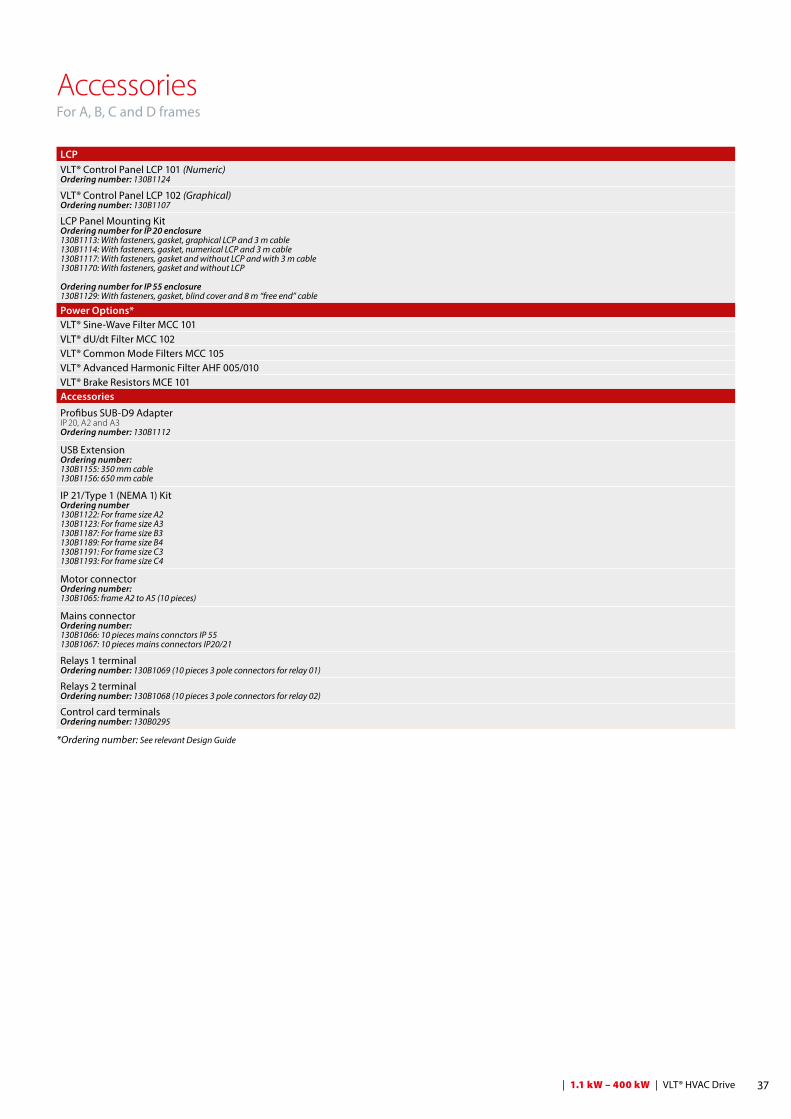
AccessoriesFor A, B, C and D frames
LCPVLT® Control Panel LCP 101 (Numeric)Ordering number: 130B1124
VLT® Control Panel LCP 102 (Graphical)Ordering number: 130B1107
LCP Panel Mounting KitOrdering number for IP 20 enclosure130B1113: With fasteners, gasket, graphical LCP and 3 m cable130B1114: With fasteners, gasket, numerical LCP and 3 m cable130B1117: With fasteners, gasket and without LCP and with 3 m cable130B1170: With fasteners, gasket and without LCP
Ordering number for IP 55 enclosure130B1129: With fasteners, gasket, blind cover and 8 m “free end” cable
Power Options*VLT® Sine-Wave Filter MCC 101VLT® dU/dt Filter MCC 102VLT® Common Mode Filters MCC 105VLT® Advanced Harmonic Filter AHF 005/010VLT® Brake Resistors MCE 101Accessories
Profibus SUB-D9 AdapterIP 20, A2 and A3 Ordering number: 130B1112
USB ExtensionOrdering number: 130B1155: 350 mm cable130B1156: 650 mm cable
IP 21/Type 1 (NEMA 1) KitOrdering number130B1122: For frame size A2 130B1123: For frame size A3 130B1187: For frame size B3 130B1189: For frame size B4 130B1191: For frame size C3 130B1193: For frame size C4
Motor connectorOrdering number: 130B1065: frame A2 to A5 (10 pieces)
Mains connectorOrdering number: 130B1066: 10 pieces mains connctors IP 55130B1067: 10 pieces mains connectors IP20/21
Relays 1 terminalOrdering number: 130B1069 (10 pieces 3 pole connectors for relay 01)
Relays 2 terminalOrdering number: 130B1068 (10 pieces 3 pole connectors for relay 02)
Control card terminalsOrdering number: 130B0295
*Ordering number: See relevant Design Guide
38 VLT® HVAC Drive | 1.1 kW – 400 kW |
Based on your selection, Danfoss manufactures the desired VLT® HVAC Drive. You will receive a fully assembled frequency converter, tested under full load conditions.
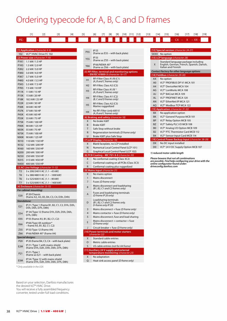
Ordering typecode for A, B, C and D frames
* Only available in the USA
[1] Application (character 4-6)102 VLT® HVAC Drive FC 102
[2] Power size (character 7-10) P1K1 1.1 kW / 1.5 HPP1K5 1.5 kW / 2.0 HPP2K2 2.2 kW / 3.0 HPP3K0 3.0 kW / 4.0 HPP3K7 3.7 kW / 5.0 HPP4K0 4.0 kW / 5.5 HPP5K5 5.5 kW / 7.5 HPP7K5 7.5 kW / 10 HPP11K 11 kW / 15 HPP15K 15 kW / 20 HPP18K 18.5 kW / 25 HPP22K 22 kW / 30 HPP30K 30 kW / 40 HPP37K 37 kW / 50 HPP45K 45 kW / 60 HPP55K 55 kW / 75 HPP75K 75 kW / 100 HPP90K 90 kW / 125 HPN55K 55 kW / 75 HPN75K 75 kW / 100 HPN90K 90 kW / 125 HPN110 110 kW / 150 HPN132 132 kW / 200 HPN160 160 kW / 250 HPN200 200 kW / 300 HPN250 250 kW / 350 HPN315 315 kW / 450 HPN400 400 kW / 550 HP[3] AC Line Voltage (character 11-12)
T2 3 x 200/240 V AC (1.1 – 45 kW)T4 3 x 380/480 V AC (1.1 – 1000 kW)T6 3 x 525/600 V AC (1.1 – 90 kW)T7 3 x 525/690 V AC (1.1 – 1400 kW)
[4] Enclosure (character 13-15) For cabinet mounting:
E20 IP 20/Chassis (frame A2, A3, B3, B4, C3, C4, D3h, D4h)
Standalone:
E21 IP 21 / Type 1 (frame B1, B2, C1, C2, D1h, D2h, D5h, D6h, D7h, D8h)
E54 IP 54/Type 12 (frame D1h, D2h, D5h, D6h, D7h, D8h)
E55 IP 55 (frame A5, B1, B2, C1, C2)
E66 IP 66/Type 4X outdoor*– frame A5, B1, B2, C1, C2)
Z55 IP 55/Type 12 (frame A4)Z66 IP 66/NEMA 4X* (frame A4)
Special designs:P20 IP 20 (frame B4, C3, C4 – with back plate)
E2M IP 21 / Type 1 with mains shield (frame D1h, D2h, D5h, D6h, D7h, D8h)
P21 IP 21 / Type 1 (frame as E21 – with back plate)
E5M IP 54 / Type 12 with mains shield (frame D1h, D2h, D5h, D6h, D7h, D8h)
P55 IP 55 (frame as E55 – with back plate)
Y55 IP 55 (frame as Z55 – with back plate)
Y66 IP 66/NEMA 4X* (frame as Z66 – with back plate)
[5] RFI filter, terminal and monitoring options – EN/IEC 61800-3 (character 16-17)
H1 RFI-Filter Class A1/B (C1)(A, B and C frames only)
H2 RFI-Filter, Class A2 (C3)
H3 RFI-Filter Class A1/B 1)
(A, B and C frames only)
H4 RFI-Filter, Class A1 (C2)(B, C and D frames only)
H5 RFI-Filter, Class A2 (C3)Marine ruggedized
HX No RFI-Filter (only 600 V)(A, B and C frames only)
[6] Braking and safety (character 18) X No brake IGBTB Brake IGBTT Safe Stop without brakeR Regeneration terminals (D frame only)U Brake IGBT plus Safe Stop
[7] LCP Display (character 19) X Blank faceplate, no LCP installedN Numerical Local Control Panel (LCP 101)G Graphical Local Control Panel (LCP 102)
[8] PCB Coating – IEC 721-3-3 (character 20) X No conformal coating (Class 3C2)C Conformal coating on all PCBs (Class 3C3)R Conformal coating plus ruggedized
[9] Mains input (character 21) X No mains option1 Mains disconnect7 Fuses (D frame only)
8 Mains disconnect and loadsharing(B1, B2, C1 and C2 frames only)
A Fuses and loadsharing terminals (D frame IP 20 only)
DLoadsharing terminals(B1, B2, C1 and C2 frames only.D-frame only IP 20)
3 Mains disconnect + fuse (D frame only)4 Mains contactor + fuse (D frame only)5 Mains disconnect, fuse and load sharing
E Mains disconnect + contactor + fuse(D frame only)
J Circuit breaker + fuse (D frame only)
[10] Power terminals and motor starters (character 22)
X Standard cable entriesO Metric cable entriesS US cable entries (not for A4 frame)
[11] Auxiliary 24 V supply and external temperature monitoring (character 23)
X No adaptationQ Heat-sink access panel (D frame only)
[12] Special version (character 24-27) SXXX No option[13] LCP language (character 28)
XStandard language package including English, German, French, Spanish, Danish, Italian and Finnish
Contact factory for other language options[14] Fieldbus (character 29-30)
AX No optionA0 VLT® PROFIBUS DP V1 MCA 101A4 VLT® DeviceNet MCA 104AG VLT® LonWorks MCA 108AJ VLT® BACnet MCA 109AL VLT® PROFINET MCA 120AN VLT® EtherNet/IP MCA 121AQ VLT® Modbus TCP MCA 122
[15] Application (character 31-32) BX No application optionBK VLT® Generel Purpose MCB 101BP VLT® Relay Option MCB 105BZ VLT® Safety PLC I/O MCB 108 B0 VLT® Analog I/O Option MCB 109B2 VLT® PTC Thermistor Card MCB 112 B4 VLT® Sensor Input Card MCB 114
[19] Control Power Backup Input (character 38-39) DX No DC input installedD0 VLT® 24 V DC Supply Option MCB 107
1) reduced motor cable length
Please beware that not all combinations are possible. Find help configuring your drive with the online configurator found under: driveconfig.danfoss.com
[1] [2] [3] [4] [5] [6] [7] [8] [9] [10] [11] [12] [13] [14] [15] [16] [17] [18] [19]
FC- – – – – – – – – – – – – – – – CX – X – XX –
39 | 1.1 kW – 400 kW | VLT® HVAC Drive
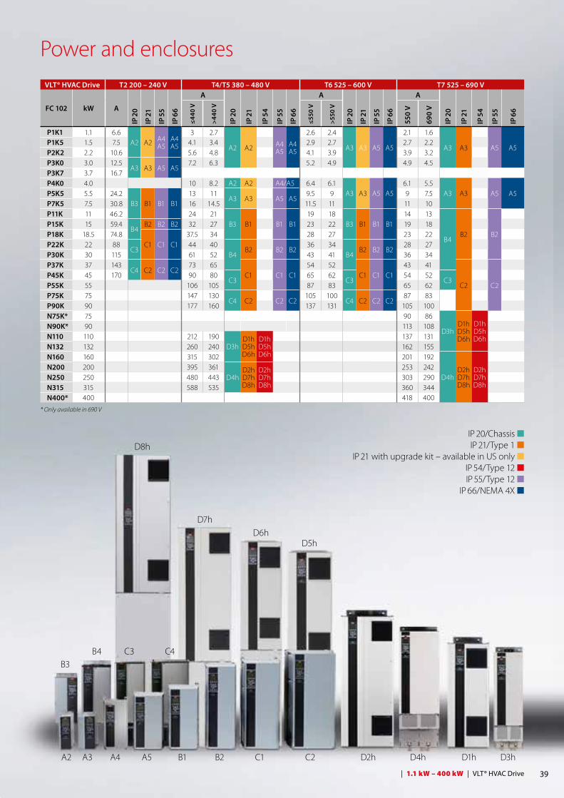
Power and enclosures
IP 20/Chassis n IP 21/Type 1 n IP 21 with upgrade kit – available in US only n IP 54/Type 12 n IP 55/Type 12 n IP 66/NEMA 4X n
B3
A2
B4
A3
C3
A4
C4
D5hD6h
D7h
D8h
A5 B1 B2 C1 C2 D2h D4h D1h D3h
VLT® HVAC Drive T2 200 – 240 V T4/T5 380 – 480 V T6 525 – 600 V T7 525 – 690 V
FC 102 kW A
IP 2
0
IP 2
1
IP 5
5
IP 6
6
A
IP 2
0
IP 2
1
IP 5
4
IP 5
5
IP 6
6
A
IP 2
0
IP 2
1
IP 5
5
IP 6
6
A
IP 2
0
IP 2
1
IP 5
4
IP 5
5
IP 6
6
≤440
V
>440
V
≤550
V
>550
V
550
V
690
V
P1K1 1.1 6.6A2 A2 A4
A5A4A5
3 2.7
A2 A2 A4A5
A4A5
2.6 2.4
A3 A3 A5 A5
2.1 1.6
A3 A3 A5 A5P1K5 1.5 7.5 4.1 3.4 2.9 2.7 2.7 2.2P2K2 2.2 10.6 5.6 4.8 4.1 3.9 3.9 3.2P3K0 3.0 12.5
A3 A3 A5 A57.2 6.3 5.2 4.9 4.9 4.5
P3K7 3.7 16.7P4K0 4.0 10 8.2 A2 A2 A4/ A5 6.4 6.1
A3 A3 A5 A56.1 5.5
A3 A3 A5 A5P5K5 5.5 24.2B3 B1 B1 B1
13 11A3 A3 A5 A5
9.5 9 9 7.5P7K5 7.5 30.8 16 14.5 11.5 11 11 10P11K 11 46.2 24 21
B3 B1 B1 B119 18
B3 B1 B1 B114 13
B4B2 B2
P15K 15 59.4B4
B2 B2 B2 32 27 23 22 19 18P18K 18.5 74.8
C1 C1 C137.5 34 28 27 23 22
P22K 22 88C3
44 40B4
B2 B2 B236 34
B4B2 B2 B2
28 27P30K 30 115 61 52 43 41 36 34P37K 37 143
C4 C2 C2 C273 65
C1 C1 C154 52
C1 C1 C143 41
C2 C2P45K 45 170 90 80
C365 62
C354 52
C3P55K 55 106 105 87 83 65 62P75K 75 147 130
C4 C2 C2 C2105 100
C4 C2 C2 C287 83
P90K 90 177 160 137 131 105 100N75K* 75 90 86
D3hD1hD5hD6h
D1hD5hD6h
N90K* 90 113 108N110 110 212 190
D3hD1hD5hD6h
D1hD5hD6h
137 131N132 132 260 240 162 155N160 160 315 302 201 192
D4hD2hD7hD8h
D2hD7hD8h
N200 200 395 361D4h
D2hD7hD8h
D2hD7hD8h
253 242N250 250 480 443 303 290N315 315 588 535 360 344N400* 400 418 400
* Only available in 690 V

Environmentally responsibleVLT® products are manufactured with respect for the safety and well-being of people and the environment.
All frequency converter factories are certified according to ISO 14001 and ISO 9001 standards.
All activities are planned and performed taking into account the individual employee, the work environment and the external en-vironment. Production takes place with a minimum of noise, smoke or other pollution and environmen-tally safe disposal of the products is pre-prepared.
UN Global CompactDanfoss has signed the UN Global Compact on social and environ-mental responsibility and our companies act responsibly towards local societies.
Impact on energy savingsOne year’s energy savings from our annual production of VLT® drives will save the energy equivalent to the energy production from a major power plant. Better process control at the same time improves product quality and reduces waste and wear on equipment.
What VLT® is all aboutDanfoss VLT Drives is the world leader among dedicated drives providers – and still gaining market share.
Dedicated to drivesDedication has been a key word since 1968, when Danfoss introduced the world’s first mass produced variable speed drive for AC motors – and named it VLT®.
Twenty five hundred employees develop, manufacture, sell and service drives and soft starters in more than one hundred countries, focused only on drives and soft starters.
Intelligent and innovative Developers at Danfoss VLT Drives have fully adopted modular principles in development as well as design, pro-duction and configuration.
Tomorrow’s features are developed in parallel using dedicated technology platforms. This allows the develop-ment of all elements to take place in parallel, at the same time reducing time to market and ensuring that customers always enjoy the benefits of the latest features.
Rely on the expertsWe take responsibility for every element of our products. The fact that we develop and produce our own features, hardware, software, power modules, printed circuit boards, and accessories is your guarantee of reliable products.
Local backup – globallyVLT® motor controllers are operating in applications all over the world and Danfoss VLT Drives’ experts located in more than 100 countries are ready to support our customers with applica-tion advice and service wherever they may be.
Danfoss VLT Drives experts don’t stop until the customer’s drive challenges are solved.
DKDD.PB.102.A3.02 VLT® is a trademark of Danfoss A/S Produced by PE-MSMBM 2014.09
Danfoss VLT Drives, Ulsnaes 1, DK-6300 Graasten, Denmark, Tel. +45 74 88 22 22, Fax +45 74 65 25 80www.danfoss.com/drives, E-mail: [email protected]