
Operating Guide VLT AQUA Drive FC 202 0.25–90 kW · ENGINEERING TOMORROW Operating Guide VLT®...
90
ENGINEERING TOMORROW Operating Guide VLT ® AQUA Drive FC 202 0.25–90 kW vlt-drives.danfoss.com
Transcript of Operating Guide VLT AQUA Drive FC 202 0.25–90 kW · ENGINEERING TOMORROW Operating Guide VLT®...

ENGINEERING TOMORROW
Operating GuideVLT® AQUA Drive FC 2020.25–90 kW
vlt-drives.danfoss.com


Contents
1 Introduction 4
1.1 Purpose of the Operating Guide 4
1.2 Additional Resources 4
1.3 Manual and Software Version 4
1.4 Product Overview 4
1.5 Approvals and Certifications 8
1.6 Disposal 8
2 Safety 9
2.1 Safety Symbols 9
2.2 Qualified Personnel 9
2.3 Safety Precautions 9
3 Mechanical Installation 11
3.1 Unpacking 11
3.2 Installation Environments 11
3.3 Mounting 12
4 Electrical Installation 14
4.1 Safety Instructions 14
4.2 EMC-compliant Installation 14
4.3 Grounding 14
4.4 Wiring Schematic 16
4.5 Access 18
4.6 Motor Connection 18
4.7 AC Mains Connection 19
4.8 Control Wiring 19
4.8.1 Control Terminal Types 19
4.8.2 Wiring to Control Terminals 21
4.8.3 Enabling Motor Operation (Terminal 27) 21
4.8.4 Voltage/Current Input Selection (Switches) 22
4.8.5 RS485 Serial Communication 22
4.9 Installation Check List 23
5 Commissioning 24
5.1 Safety Instructions 24
5.2 Applying Power 24
5.3 Local Control Panel Operation 24
5.3.1 Graphic Local Control Panel Layout 24
5.3.2 Parameter Settings 26
Contents Operating Guide
MG20MD02 Danfoss A/S © 10/2016 All rights reserved. 1
5.3.3 Uploading/Downloading Data to/from the LCP 26
5.3.4 Changing Parameter Settings 26
5.3.5 Restoring Default Settings 26
5.4 Basic Programming 27
5.4.1 Commissioning with SmartStart 27
5.4.2 Commissioning via [Main Menu] 27
5.4.3 Asynchronous Motor Set-up 28
5.4.4 PM Motor Setup in VVC+ 28
5.4.5 SynRM Motor Set-up with VVC+ 29
5.4.6 Automatic Energy Optimization (AEO) 30
5.4.7 Automatic Motor Adaptation (AMA) 30
5.5 Checking Motor Rotation 31
5.6 Local-control Test 31
5.7 System Start-up 31
6 Application Set-up Examples 32
7 Maintenance, Diagnostics, and Troubleshooting 36
7.1 Maintenance and Service 36
7.2 Status Messages 36
7.3 Warning and Alarm Types 38
7.4 List of Warnings and Alarms 39
7.5 Troubleshooting 46
8 Specifications 49
8.1 Electrical Data 49
8.1.1 Mains Supply 1x200–240 V AC 49
8.1.2 Mains Supply 3x200–240 V AC 50
8.1.3 Mains Supply 1x380–480 V AC 52
8.1.4 Mains Supply 3x380–480 V AC 53
8.1.5 Mains Supply 3x525–600 V AC 57
8.1.6 Mains Supply 3x525–690 V AC 61
8.2 Mains Supply 64
8.3 Motor Output and Motor Data 64
8.4 Ambient Conditions 65
8.5 Cable Specifications 65
8.6 Control Input/Output and Control Data 65
8.7 Connection Tightening Torques 68
8.8 Fuses and Circuit Breakers 69
8.9 Power Ratings, Weight, and Dimensions 76
9 Appendix 78
Contents VLT® AQUA Drive FC 202
2 Danfoss A/S © 10/2016 All rights reserved. MG20MD02

9.1 Symbols, Abbreviations, and Conventions 78
9.2 Parameter Menu Structure 78
Index 84
Contents Operating Guide
MG20MD02 Danfoss A/S © 10/2016 All rights reserved. 3

1 Introduction
1.1 Purpose of the Operating Guide
This operating guide provides information for safe instal-lation and commissioning of the frequency converter.
The operating guide is intended for use by qualifiedpersonnel.Read and follow the instructions to use the frequencyconverter safely and professionally, and pay particularattention to the safety instructions and general warnings.Always keep this operating guide available with thefrequency converter.
VLT® is a registered trademark.
1.2 Additional Resources
Other resources are available to understand advancedfrequency converter functions and programming.
• The VLT® AQUA Drive FC 202 Programming Guideprovides greater detail on working withparameters and many application examples.
• The VLT® AQUA Drive FC 202 Design Guideprovides detailed information about capabilitiesand functionality to design motor controlsystems.
• Instructions for operation with optionalequipment.
Supplementary publications and manuals are availablefrom Danfoss. See www.vlt-drives.danfoss.com/Support/Technical-Documentation/ for listings.
1.3 Manual and Software Version
This manual is regularly reviewed and updated. Allsuggestions for improvement are welcome.
Table 1.1 shows the manual version and the correspondingsoftware version.
Edition Remarks Softwareversion
MG20MDxx The parameter list is updated toreflect software version 2.6x. Editorial
update.
2.6x
Table 1.1 Manual and Software Version
1.4 Product Overview
1.4.1 Intended Use
The frequency converter is an electronic motor controllerintended for:
• Regulation of motor speed in response to systemfeedback or to remote commands from externalcontrollers. A power drive system consists of thefrequency converter, the motor, and equipmentdriven by the motor.
• System and motor status surveillance.
Depending on configuration, the frequency converter canbe used in standalone applications or form part of a largerappliance or installation.
The frequency converter is allowed for use in residential,industrial, and commercial environments in accordancewith local laws, standards, and emission limits as describedin the design guide.
Single-phase frequency converters (S2 and S4) installedin the EU
The following limitations apply:• Units with an input current below 16 A and an
input power above 1 kW (1.5 hp) are onlyintended for professional use in trades,professions, or industries and not for sale to thegeneral public.
• Designated application areas are public pools,public water supplies, agriculture, commercialbuildings, and industries. All other single-phaseunits are only intended for use in private low-voltage systems interfacing with public supplyonly at a medium or high-voltage level.
• Operators of private systems must ensure thatthe EMC environment complies with IEC610000-3-6 and/or the contractual agreements.
NOTICEIn a residential environment, this product can causeradio interference, in which case supplementarymitigation measures may be required.
Foreseeable misuseDo not use the frequency converter in applications, whichare non-compliant with specified operating conditions andenvironments. Ensure compliance with the conditionsspecified in chapter 8 Specifications.
Introduction VLT® AQUA Drive FC 202
4 Danfoss A/S © 10/2016 All rights reserved. MG20MD02
11

1.4.2 Features
The VLT® AQUA Drive FC 202 is designed for water andwastewater applications. The range of standard andoptional features includes:
• Cascade control.
• Dry run detection.
• End-of-curve detection.
• SmartStart.
• Motor alternation.
• Deragging.
• 2-step ramps.
• Flow confirmation.
• Check valve protection.
• Safe Torque Off.
• Low flow detection.
• Pre/post lubrication.
• Pipe fill mode.
• Sleep mode.
• Real-time clock.
• User-configurable info texts.
• Warnings and alarms.
• Password protection.
• Overload protection.
• Smart logic control.
• Dual power rating (high/normal overload).
Introduction Operating Guide
MG20MD02 Danfoss A/S © 10/2016 All rights reserved. 5
1 1

1.4.3 Exploded Views
1
23
4
5
6
7
8
9
10
111213
14
8
15
16
17
18
130B
B492
.11
1 Local control panel (LCP) 10 Motor output terminals 96 (U), 97 (V), 98 (W)
2 RS485 fieldbus connector (+68, -69) 11 Relay 2 (01, 02, 03)
3 Analog I/O connector 12 Relay 1 (04, 05, 06)
4 LCP input plug 13 Brake (-81, +82) and load sharing (-88, +89) terminals
5 Analog switches (A53), (A54) 14 Mains input terminals 91 (L1), 92 (L2), 93 (L3)
6 Cable shield connector 15 USB connector
7 Ground termination plate 16 Fieldbus terminal switch
8 Grounding clamp (PE) 17 Digital I/O and 24 V supply
9 Shielded cable grounding clamp and strain relief 18 Cover
Illustration 1.1 Exploded View Enclosure Size A, IP20
Introduction VLT® AQUA Drive FC 202
6 Danfoss A/S © 10/2016 All rights reserved. MG20MD02
11

1
2
3
4
56
7
8
9
10
11
12 13
1617
1819
1415
FAN MOUNTING
QDF-30
DC- DC+
Remove jumper to activate Safe Stop
Max. 24 Volt !12 13 18 19 27 29 32 33 20 37
0605
0403
0201
130B
B493
.11
61 68 69 39 42 50 53 54 55
1 Local control panel (LCP) 11 Relay 2 (04, 05, 06)
2 Cover 12 Lifting ring
3 RS485 fieldbus connector 13 Mounting slot
4 Digital I/O and 24 V supply 14 Grounding clamp (PE)
5 Analog I/O connector 15 Cable shield connector
6 Cable shield connector 16 Brake terminal (-81, +82)
7 USB connector 17 Load sharing terminal (DC bus) (-88, +89)
8 Fieldbus terminal switch 18 Motor output terminals 96 (U), 97 (V), 98 (W)
9 Analog switches (A53), (A54) 19 Mains input terminals 91 (L1), 92 (L2), 93 (L3)
10 Relay 1 (01, 02, 03) – –
Illustration 1.2 Exploded View Enclosure Sizes B and C, IP55 and IP66
Introduction Operating Guide
MG20MD02 Danfoss A/S © 10/2016 All rights reserved. 7
1 1

Illustration 1.3 is a block diagram of the internalcomponents of the frequency converter.
Area Title Functions
1 Mains input• 3-phase AC mains supply to the
frequency converter.
2 Rectifier
• The rectifier bridge converts theAC input to DC current to supplyinverter power.
3 DC bus• The intermediate DC bus circuit
handles the DC current.
4 DC reactors
• Filter the intermediate DC circuitvoltage.
• Prove mains transient protection.
• Reduce RMS current.
• Raise the power factor reflectedback to the line.
• Reduce harmonics on the ACinput.
5 Capacitor bank
• Stores the DC power.
• Provides ride-through protectionfor short power losses.
6 Inverter
• Converts the DC into a controlledPWM AC waveform for acontrolled variable output to themotor.
7 Output to motor• Regulated 3-phase output power
to the motor.
8 Control circuitry
• Input power, internal processing,output, and motor current aremonitored to provide efficientoperation and control.
• User interface and externalcommands are monitored andperformed.
• Status output and control can beprovided.
Illustration 1.3 Frequency Converter Block Diagram
1.4.4 Enclosure Sizes and Power Ratings
For enclosure sizes and power ratings of the frequencyconverters, refer to chapter 8.9 Power Ratings, Weight, andDimensions.
1.5 Approvals and Certifications
Table 1.2 Approvals and Certifications
More approvals and certifications are available. Contact thelocal Danfoss partner. Frequency converters of enclosuresize T7 (525–690 V) are UL certified for only 525–600 V.
The frequency converter complies with UL 508C thermalmemory retention requirements. For more information,refer to the section Motor Thermal Protection in theproduct-specific design guide.
For compliance with the European Agreement concerningInternational Carriage of Dangerous Goods by InlandWaterways (ADN), refer to ADN-compliant Installation in theproduct-specific design guide.
1.6 Disposal
Do not dispose of equipment containingelectrical components together withdomestic waste.Collect it separately in accordance withlocal and currently valid legislation.
Introduction VLT® AQUA Drive FC 202
8 Danfoss A/S © 10/2016 All rights reserved. MG20MD02
11

2 Safety
2.1 Safety Symbols
The following symbols are used in this guide:
WARNINGIndicates a potentially hazardous situation that couldresult in death or serious injury.
CAUTIONIndicates a potentially hazardous situation that couldresult in minor or moderate injury. It can also be used toalert against unsafe practices.
NOTICEIndicates important information, including situations thatcan result in damage to equipment or property.
2.2 Qualified Personnel
Correct and reliable transport, storage, installation,operation, and maintenance are required for the trouble-free and safe operation of the frequency converter. Onlyqualified personnel are allowed to install and operate thisequipment.
Qualified personnel are defined as trained staff, who areauthorized to install, commission, and maintain equipment,systems, and circuits in accordance with pertinent laws andregulations. Also, the qualified personnel must be familiarwith the instructions and safety measures described in thismanual.
2.3 Safety Precautions
WARNINGHIGH VOLTAGEFrequency converters contain high voltage whenconnected to AC mains input, DC supply, or load sharing.Failure to perform installation, start-up, and maintenanceby qualified personnel can result in death or seriousinjury.
• Only qualified personnel must perform instal-lation, start-up, and maintenance.
WARNINGUNINTENDED STARTWhen the frequency converter is connected to AC mains,DC supply, or load sharing, the motor may start at anytime. Unintended start during programming, service, orrepair work can result in death, serious injury, orproperty damage. The motor can start via an externalswitch, a fieldbus command, an input reference signalfrom the LCP, or after a cleared fault condition.
To prevent unintended motor start:• Disconnect the frequency converter from the
mains.
• Press [Off/Reset] on the LCP beforeprogramming parameters.
• Completely wire and assemble the frequencyconverter, motor, and any driven equipmentbefore connecting the frequency converter toAC mains, DC supply, or load sharing.
WARNINGDISCHARGE TIMEThe frequency converter contains DC-link capacitors,which can remain charged even when the frequencyconverter is not powered. High voltage can be presenteven when the warning LED indicator lights are off.Failure to wait the specified time after power has beenremoved before performing service or repair work canresult in death or serious injury.
• Stop the motor.
• Disconnect AC mains and remote DC-link powersupplies, including battery back-ups, UPS, andDC-link connections to other frequencyconverters.
• Disconnect or lock PM motor.
• Wait for the capacitors to discharge fully. Theminimum duration of waiting time is specifiedin Table 2.1.
• Before performing any service or repair work,use an appropriate voltage measuring device tomake sure that the capacitors are fullydischarged.
Safety Operating Guide
MG20MD02 Danfoss A/S © 10/2016 All rights reserved. 9
2 2

Voltage [V]Minimum waiting time (minutes)
4 7 15
200–240 0.25–3.7 kW(0.34–5 hp)
– 5.5–45 kW(7.5–60 hp)
380–480 0.37–7.5 kW(0.5–10 hp)
– 11–90 kW(15–121 hp)
525–600 0.75–7.5 kW(1–10 hp)
– 11–90 kW(15–121 hp)
525–690 – 1.1–7.5 kW(1.5–10 hp)
11–90 kW(15–121 hp)
Table 2.1 Discharge Time
WARNINGLEAKAGE CURRENT HAZARDLeakage currents exceed 3.5 mA. Failure to ground thefrequency converter properly can result in death orserious injury.
• Ensure the correct grounding of the equipmentby a certified electrical installer.
WARNINGEQUIPMENT HAZARDContact with rotating shafts and electrical equipmentcan result in death or serious injury.
• Ensure that only trained and qualified personnelperform installation, start-up, and maintenance.
• Ensure that electrical work conforms to nationaland local electrical codes.
• Follow the procedures in this guide.
WARNINGUNINTENDED MOTOR ROTATIONWINDMILLINGUnintended rotation of permanent magnet motorscreates voltage and can charge the unit, resulting indeath, serious injury, or equipment damage.
• Ensure that permanent magnet motors areblocked to prevent unintended rotation.
CAUTIONINTERNAL FAILURE HAZARDAn internal failure in the frequency converter can resultin serious injury when the frequency converter is notproperly closed.
• Ensure that all safety covers are in place andsecurely fastened before applying power.
Safety VLT® AQUA Drive FC 202
10 Danfoss A/S © 10/2016 All rights reserved. MG20MD02
22

3 Mechanical Installation
3.1 Unpacking
3.1.1 Items Supplied
Items supplied may vary according to product configu-ration.
• Make sure the items supplied and the informationon the nameplate correspond to the order confir-mation.
• Check the packaging and the frequency convertervisually for damage caused by inappropriatehandling during shipment. File any claim fordamage with the carrier. Retain damaged partsfor clarification.
130B
D66
6.10
CHASSIS/ IP20 Tamb.45 C/113 F
VLT
MADE IN DENMARK
R
P/N: 131F6653 S/N: 038010G502
45kW(400V) / 60HP(460V)
IN: 3x380-480V 50/60Hz 82/73A
OUT: 3x0-Vin 0-590Hz 90/80Ao
CAUTION:See manual for special condition/mains fusevoir manual de conditions speclales/fusibles
WARNING:Stored charge, wait 15 min.Charge residuelle, attendez 15 min.
* 1 3 1 F 6 6 5 3 0 3 8 0 1 0 G 5 0 2 *
`
AQUA Drivewww.danfoss.com
T/C: FC-202P45KT4E20H1XGXXXXSXXXXAXBXCXXXXDX
Listed 76X1 E134261 Ind. Contr. Eq.
o
`
12
4
5
6
7 8
9
10
3
1 Type code
2 Ordering number
3 Serial number
4 Power rating
5Input voltage, frequency, and current (at low/highvoltages)
6Output voltage, frequency, and current (at low/highvoltages)
7 Enclosure type and IP rating
8 Maximum ambient temperature
9 Certifications
10 Discharge time (Warning)
Illustration 3.1 Product Nameplate (Example)
NOTICEDo not remove the nameplate from the frequencyconverter. Removing the nameplate voids the warranty.
3.1.2 Storage
Ensure that the requirements for storage are fulfilled. Referto chapter 8.4 Ambient Conditions for further details.
3.2 Installation Environments
NOTICEIn environments with airborne liquids, particles, orcorrosive gases, ensure that the IP/type rating of theequipment matches the installation environment. Failureto meet requirements for ambient conditions can reducethe lifetime of the frequency converter. Ensure thatrequirements for air humidity, temperature, and altitudeare met.
Vibration and shockThe frequency converter complies with requirements forunits mounted on the walls and floors of productionpremises, and in panels bolted to walls or floors.
For detailed ambient conditions specifications, refer to chapter 8.4 Ambient Conditions.
Mechanical Installation Operating Guide
MG20MD02 Danfoss A/S © 10/2016 All rights reserved. 11
3 3

3.3 Mounting
NOTICEImproper mounting can result in overheating andreduced performance.
Cooling
• Ensure that top and bottom clearance for aircooling is provided. See Illustration 3.2 forclearance requirements.
a
a
130B
D52
8.10
Enclosure A2–A5 B1–B4 C1, C3 C2, C4
a [mm (in)] 100 (3.9) 200 (7.9) 200 (7.9) 225 (8.9)
Illustration 3.2 Top and Bottom Cooling Clearance
Lifting• To determine a safe lifting method, check the
weight of the unit, see chapter 8.9 Power Ratings,Weight, and Dimensions.
• Ensure that the lifting device is suitable for thetask.
• If necessary, plan for a hoist, crane, or forklift withthe appropriate rating to move the unit.
• For lifting, use the hoist rings on the unit, whenprovided.
Mounting1. Ensure that the strength of the mounting location
supports the unit weight. The frequencyconverter allows side-by-side installation.
2. Locate the unit as near to the motor as possible.Keep the motor cables as short as possible.
3. Mount the unit vertically to a solid flat surface orto the optional backplate to provide coolingairflow.
4. Use the slotted mounting holes on the unit forwall mounting, when provided.
Mounting with backplate and railings
130B
D50
4.10
Illustration 3.3 Proper Mounting with Backplate
NOTICEA backplate is required when mounted on railings.
C
a
b
130B
A64
8.12
f
e
B
A
a
d
e
b
c
Illustration 3.4 Top and Bottom Mounting Holes (Seechapter 8.9 Power Ratings, Weight, and Dimensions)
Mechanical Installation VLT® AQUA Drive FC 202
12 Danfoss A/S © 10/2016 All rights reserved. MG20MD02
33

a
e
f
130B
A71
5.12
Illustration 3.5 Top and Bottom Mounting Holes (B4, C3, andC4)
Mechanical Installation Operating Guide
MG20MD02 Danfoss A/S © 10/2016 All rights reserved. 13
3 3

4 Electrical Installation
4.1 Safety Instructions
See chapter 2 Safety for general safety instructions.
WARNINGINDUCED VOLTAGEInduced voltage from output motor cables that runtogether can charge equipment capacitors, even with theequipment turned off and locked out. Failure to runoutput motor cables separately or to use shielded cablescould result in death or serious injury.
• Run output motor cables separately, or
• Use shielded cables.
CAUTIONSHOCK HAZARDThe frequency converter can cause a DC current in thePE conductor. Failure to follow the recommendation maylead to the RCD not providing the intended protection.
• When a residual current-operated protectivedevice (RCD) is used for protection againstelectrical shock, only an RCD of Type B isallowed on the supply side.
Overcurrent protection• Extra protective equipment, such as short-circuit
protection or motor thermal protection betweenfrequency converter and motor, is required forapplications with multiple motors.
• Input fusing is required to provide short circuitand overcurrent protection. If not factory-supplied, the installer must provide fuses. Seemaximum fuse ratings in chapter 8.8 Fuses andCircuit Breakers.
Wire type and ratings• All wiring must comply with local and national
regulations regarding cross-section and ambienttemperature requirements.
• Power connection wire recommendation:Minimum 75 °C (167 °F) rated copper wire.
See chapter 8.1 Electrical Data and chapter 8.5 Cable Specifi-cations for recommended wire sizes and types.
4.2 EMC-compliant Installation
To obtain an EMC-compliant installation, follow theinstructions provided in chapter 4.3 Grounding, chapter 4.4 Wiring Schematic, chapter 4.6 Motor Connection,and chapter 4.8 Control Wiring.
4.3 Grounding
WARNINGLEAKAGE CURRENT HAZARDLeakage currents exceed 3.5 mA. Failure to ground thefrequency converter properly could result in death orserious injury.
• Ensure the correct grounding of the equipmentby a certified electrical installer.
For electrical safety• Ground the frequency converter in accordance
with applicable standards and directives.
• Use a dedicated ground wire for input power,motor power, and control wiring.
• Do not ground 1 frequency converter to anotherin a daisy-chain fashion (see Illustration 4.1).
• Keep the ground wire connections as short aspossible.
• Follow motor manufacturer wiring requirements.
• Minimum cable cross-section: 10 mm2 (7 AWG).Separately terminate 2 ground wires, bothcomplying with the dimension requirements.
130B
C500
.10FC 1
FC 1
FC 2
FC 2
FC 3
FC 3
PE
PE
Illustration 4.1 Grounding Principle
Electrical Installation VLT® AQUA Drive FC 202
14 Danfoss A/S © 10/2016 All rights reserved. MG20MD02
44

For EMC-compliant installation• Establish electrical contact between the cable
shield and the frequency converter enclosure byusing metal cable glands or by using the clampsprovided on the equipment (see chapter 4.6 MotorConnection).
• Use high-strand wire to reduce burst transient.
• Do not use pigtails.
NOTICEPOTENTIAL EQUALIZATIONRisk of burst transient when the ground potentialbetween the frequency converter and the control systemis different. Install equalizing cables between the systemcomponents. Recommended cable cross-section: 16 mm2
(6 AWG).
Electrical Installation Operating Guide
MG20MD02 Danfoss A/S © 10/2016 All rights reserved. 15
4 4

4.4 Wiring Schematic
130B
D55
2.12
3-phasepowerinput
DC bus Switch ModePower Supply
Motor
Analog Output
Interface
relay1
relay2
ON=TerminatedOFF=Open
Brakeresistor
91 (L1)92 (L2)93 (L3)
PE
88 (-)89 (+)
50 (+10 V OUT)
53 (A IN)
54 (A IN)
55 (COM A IN)0/4-20 mA
12 (+24 V OUT)
13 (+24 V OUT)
37 (D IN)
18 (D IN)
20 (COM D IN)
10 V DC15 mA 200 mA
+ - + -
(U) 96(V) 97(W) 98(PE) 99
(COM A OUT) 39
(A OUT) 42
(P RS-485) 68
(N RS-485) 69
(COM RS-485) 61
0 V
5V
S801
0/4-20 mA
RS-485RS-485
03
+10 V DC0/-10 V DC -
+10 V DC
+10 V DC0/4-20 mA
0/-10 V DC-
240 V AC, 2 A
24 V DC
02
01
05
04
06
24 V (NPN) 0 V (PNP)
0 V (PNP)24 V (NPN)
19 (D IN)
24 V (NPN) 0 V (PNP)27
24 V
0 V
(D IN/OUT)
0 V (PNP)24 V (NPN)
(D IN/OUT)
0 V
24 V29
24 V (NPN) 0 V (PNP)
0 V (PNP)24 V (NPN)
33 (D IN)
32 (D IN)
12
ON
A53
ON2
1A54ON=0/4-20 mAOFF=0/-10 V DC - +10 V DC
95
P 5-00
21 O
N
S801
(R+) 82
(R-) 81
: Chassis
: PE
**
240 V AC, 2 A
400 V AC, 2 A
* : Ground 1
: Ground 2
: Ground
Illustration 4.2 Basic Wiring Schematic
A=Analog, D=Digital*Terminal 37 (optional) is used for Safe Torque Off. For Safe Torque Off installation instructions, refer to the VLT® FrequencyConverters - Safe Torque Off Operating Guide.**Do not connect cable shield.
NOTICEActual configurations vary with unit types and optional equipment.
Electrical Installation VLT® AQUA Drive FC 202
16 Danfoss A/S © 10/2016 All rights reserved. MG20MD02
44

130B
D52
9.12
1
2
3
4
5
6
7
8
9
L1L2L3PE
10 11 PE
u
v
w
1 PLC 6 Cable gland
2 Frequency converter 7 Motor, 3-phase, and PE
3 Output contactor 8 Mains, 3-phase, and reinforced PE
4 Grounding rail (PE) 9 Control wiring
5 Cable insulation (stripped) 10 Equalizing minimum 16 mm2 (5 AWG)
Illustration 4.3 EMC-compliant Connection of Mains
NOTICEEMC INTERFERENCEUse shielded cables for motor and control wiring and separate cables for input power, motor wiring, and control wiring.Failure to isolate power, motor, and control cables can result in unintended behavior or reduced performance. Minimumclearance requirement between power, motor, and control cables is 200 mm (7.9 in).
Electrical Installation Operating Guide
MG20MD02 Danfoss A/S © 10/2016 All rights reserved. 17
4 4

4.5 Access
1. Remove the cover with a screwdriver (SeeIllustration 4.4) or by loosening the attachingscrews (See Illustration 4.5).
130B
T248
.10
Illustration 4.4 Access to Wiring for IP20 and IP21 Enclosures
130B
T334
.10
Illustration 4.5 Access to Wiring for IP55 and IP66 Enclosures
Tighten the cover screws using the tighteningtorques specified in Table 4.1.
Enclosure IP55 IP66
A4/A5 2 (18) 2 (18)
B1/B2 2.2 (19) 2.2 (19)
C1/C2 2.2 (19) 2.2 (19)
No screws to tighten for A2/A3/B3/B4/C3/C4.
Table 4.1 Tightening Torques for Covers [N•m (in-lb)]
4.6 Motor Connection
WARNINGINDUCED VOLTAGEInduced voltage from output motor cables that runtogether can charge equipment capacitors, even with theequipment turned off and locked out. Failure to runoutput motor cables separately or use shielded cablescould result in death or serious injury.
• Run output motor cables separately, or
• Use shielded cables.
• Comply with local and national electrical codesfor cable sizes. For maximum wire sizes, see chapter 8.1 Electrical Data.
• Follow motor manufacturer wiring requirements.
• Motor wiring knockouts or access panels areprovided at the base of IP21 (NEMA1/12) andhigher units.
• Do not wire a starting or pole-changing device(for example Dahlander motor or slip ringasynchronous motor) between the frequencyconverter and the motor.
Procedure
1. Strip a section of the outer cable insulation.
2. Position the stripped wire under the cable clampto establish mechanical fixation and electricalcontact between the cable shield and ground.
3. Connect the ground wire to the nearestgrounding terminal in accordance with thegrounding instructions provided in chapter 4.3 Grounding, see Illustration 4.6.
4. Connect the 3-phase motor wiring to terminals96 (U), 97 (V), and 98 (W), see Illustration 4.6.
5. Tighten the terminals in accordance with theinformation provided in chapter 8.7 ConnectionTightening Torques.
Electrical Installation VLT® AQUA Drive FC 202
18 Danfoss A/S © 10/2016 All rights reserved. MG20MD02
44

130B
D53
1.10
UV
W
9697
98
Illustration 4.6 Motor Connection
Illustration 4.7 shows mains input, motor, and groundingfor basic frequency converters. Actual configurations varywith unit types and optional equipment.
+DC BR- B
MA
I NS
L1 L2 L391 92 93
RELA
Y 1
RE
LAY
2
99 U V W
MOTOR
99
130B
F948
.10
Illustration 4.7 Example of Motor, Mains, and Ground Wiring
4.7 AC Mains Connection
• Size the wiring based on the input current of thefrequency converter. For maximum wire sizes, see chapter 8.1 Electrical Data.
• Comply with local and national electrical codesfor cable sizes.
Procedure1. Connect the 3-phase AC input power wiring to
terminals L1, L2, and L3 (see Illustration 4.7).
2. Depending on the configuration of theequipment, connect the input power to themains input terminals or the input disconnect.
3. Ground the cable in accordance with thegrounding instructions provided in chapter 4.3 Grounding.
4. When supplied from an isolated mains source (ITmains or floating delta) or TT/TN-S mains with agrounded leg (grounded delta), ensure thatparameter 14-50 RFI Filter is set to [0] Off to avoiddamage to the DC link and to reduce groundcapacity currents in accordance with IEC 61800-3.
4.8 Control Wiring
• Isolate the control wiring from the high-powercomponents in the frequency converter.
• When the frequency converter is connected to athermistor, ensure that the thermistor controlwiring is shielded and reinforced/doubleinsulated. A 24 V DC supply voltage isrecommended. See Illustration 4.8.
4.8.1 Control Terminal Types
Illustration 4.8 and Illustration 4.9 show the removablefrequency converter connectors. Terminal functions anddefault settings are summarized in Table 4.2.
1
43
2
130B
B921
.12
Illustration 4.8 Control Terminal Locations
Electrical Installation Operating Guide
MG20MD02 Danfoss A/S © 10/2016 All rights reserved. 19
4 4

130B
B931
.11
12 13 18 19 27 29 32 33 20 37
39696861 42 50 53 54 55
1
32
Illustration 4.9 Terminal Numbers
• Connector 1 provides:
- 4 programmable digital inputs terminals.
- 2 extra digital terminals programmableas either input or output.
- 24 V DC terminal supply voltage.
- Optional customer supplied 24 V DCvoltage.
• Connector 2 terminals (+)68 and (-)69 are for anRS485 serial communication connection.
• Connector 3 provides:
- 2 analog inputs.
- 1 analog output.
- 10 V DC supply voltage.
- Commons for the inputs and output.
• Connector 4 is a USB port available for use withthe MCT 10 Set-up Software.
Terminal description
Terminal ParameterDefaultsetting Description
Digital Inputs/Outputs
12, 13 – +24 V DC 24 V DC supply voltagefor digital inputs andexternal transducers.Maximum outputcurrent 200 mA for all24 V loads.
Terminal description
Terminal ParameterDefaultsetting Description
18
Parameter 5-10 Terminal 18 Digital
Input [8] Start
Digital inputs.
19 Parameter 5-11 Terminal 19 Digital
Input[0] Nooperation
32 Parameter 5-14 Terminal 32 Digital
Input[0] Nooperation
33 Parameter 5-15 Terminal 33 Digital
Input[0] Nooperation
27 Parameter 5-12 Terminal 27 Digital
Input[2] Coastinverse
For digital input oroutput. Default settingis input.
29 Parameter 5-13 Terminal 29 Digital
Input
[14] Jog
20 – – Common for digitalinputs and 0 Vpotential for 24 Vsupply.
37 – Safe TorqueOff (STO)
Safe input (optional).Used for STO.
Analog Inputs/Outputs
39 ––
Common for analogoutput
42 Parameter 6-50 Terminal 42 Output
Speed 0 –High Limit
Programmable analogoutput. 0–20 mA or 4–20 mA at a maximum
of 500 Ω50 – +10 V DC 10 V DC analog supply
voltage for potenti-ometer or thermistor.15 mA maximum
53
Parametergroup 6-1*
AnalogInput 53 Reference
Analog input. Forvoltage or current.Switches A53 and A54select mA or V.
54 Parametergroup 6-2*
AnalogInput 54
Feedback
55 ––
Common for analoginput
Serial Communication
Electrical Installation VLT® AQUA Drive FC 202
20 Danfoss A/S © 10/2016 All rights reserved. MG20MD02
44

Terminal description
Terminal ParameterDefaultsetting Description
61 – – Integrated RC-Filter forcable shield. ONLY forconnecting the shield ifEMC problems occur.
68 (+)
Parametergroup 8-3*
FC PortSettings
–
RS485 Interface. Acontrol card switch isprovided fortermination resistance.
69 (-) Parametergroup 8-3*
FC PortSettings
–
Relays
01, 02, 03
Parameter 5-40 Function Relay [0] [9] Alarm
Form C relay output.For AC or DC voltageand resistive orinductive loads.
04, 05, 06 Parameter 5-40 Function Relay [1]
[5] Running
Table 4.2 Terminal Description
Extra terminals• 2 form C relay outputs. Location of the outputs
depends on frequency converter configuration.
• Terminals on built-in optional equipment. See themanual provided with the equipment option.
4.8.2 Wiring to Control Terminals
Control terminal connectors can be unplugged from thefrequency converter for ease of installation, as shown inIllustration 4.10.
NOTICEKeep control wires as short as possible and separatefrom high-power cables to minimize interference.
1. Open the contact by inserting a small screwdriverinto the slot above the contact and push thescrewdriver slightly upwards.
130B
D54
6.11
21
10 m
m[0
.4 in
ches
]
12 13 18 19 27 29 32 33
Illustration 4.10 Connecting Control Wires
2. Insert the bare control wire into the contact.
3. Remove the screwdriver to fasten the control wireinto the contact.
4. Ensure that the contact is firmly established andnot loose. Loose control wiring can be the sourceof equipment faults or less than optimaloperation.
See chapter 8.5 Cable Specifications for control terminalwiring sizes and chapter 6 Application Set-up Examples fortypical control wiring connections.
4.8.3 Enabling Motor Operation(Terminal 27)
A jumper wire is required between terminal 12 (or 13) andterminal 27 for the frequency converter to operate whenusing factory default programming values.
• Digital input terminal 27 is designed to receive24 V DC external interlock command.
• When no interlock device is used, wire a jumperbetween control terminal 12 (recommended) or13 to terminal 27. The jumper provides aninternal 24 V signal on terminal 27.
• When the status line at the bottom of the LCPreads AUTO REMOTE COAST, it indicates that theunit is ready to operate but is missing an inputsignal on terminal 27.
• When factory installed optional equipment iswired to terminal 27, do not remove that wiring.
Electrical Installation Operating Guide
MG20MD02 Danfoss A/S © 10/2016 All rights reserved. 21
4 4

4.8.4 Voltage/Current Input Selection(Switches)
The analog input terminals 53 and 54 allow setting ofinput signal to voltage (0–10 V) or current (0/4–20 mA).
Default parameter setting• Terminal 53: Speed reference signal in open loop
(see parameter 16-61 Terminal 53 Switch Setting).
• Terminal 54: Feedback signal in closed loop (seeparameter 16-63 Terminal 54 Switch Setting).
NOTICEDisconnect power to the frequency converter beforechanging switch positions.
1. Remove the LCP (see Illustration 4.11).
2. Remove any optional equipment covering theswitches.
3. Set switches A53 and A54 to select the signaltype. U selects voltage, I selects current.
130B
D53
0.10
12
N
O
VLT
BUSTER.OFF-ON
A53 A54U- I U- I
Illustration 4.11 Location of Terminal 53 and 54 Switches
To run STO, more wiring for the frequency converter isrequired. Refer to VLT® Frequency Converters Safe Torque OffOperating Guide for further information.
4.8.5 RS485 Serial Communication
Connect RS485 serial communication wiring to terminals(+)68 and (-)69.
• Use shielded serial communication cable(recommended).
• See chapter 4.3 Grounding for proper grounding.
61
68
69
+
130B
B489
.10
RS485
Illustration 4.12 Serial Communication Wiring Diagram
For basic serial communication set-up, select the following:1. Protocol type in parameter 8-30 Protocol.
2. Frequency converter address inparameter 8-31 Address.
3. Baud rate in parameter 8-32 Baud Rate.
• 2 communication protocols are internal to thefrequency converter:
- Danfoss FC.
- Modbus RTU.
• Functions can be programmed remotely usingthe protocol software and RS485 connection or inparameter group 8-** Communications andOptions.
• Selecting a specific communication protocolchanges various default parameter settings tomatch that protocol’s specifications and makesmore protocol-specific parameters available.
• Option cards for the frequency converter areavailable to provide extra communicationprotocols. See the option card documentation forinstallation and operation instructions.
Electrical Installation VLT® AQUA Drive FC 202
22 Danfoss A/S © 10/2016 All rights reserved. MG20MD02
44
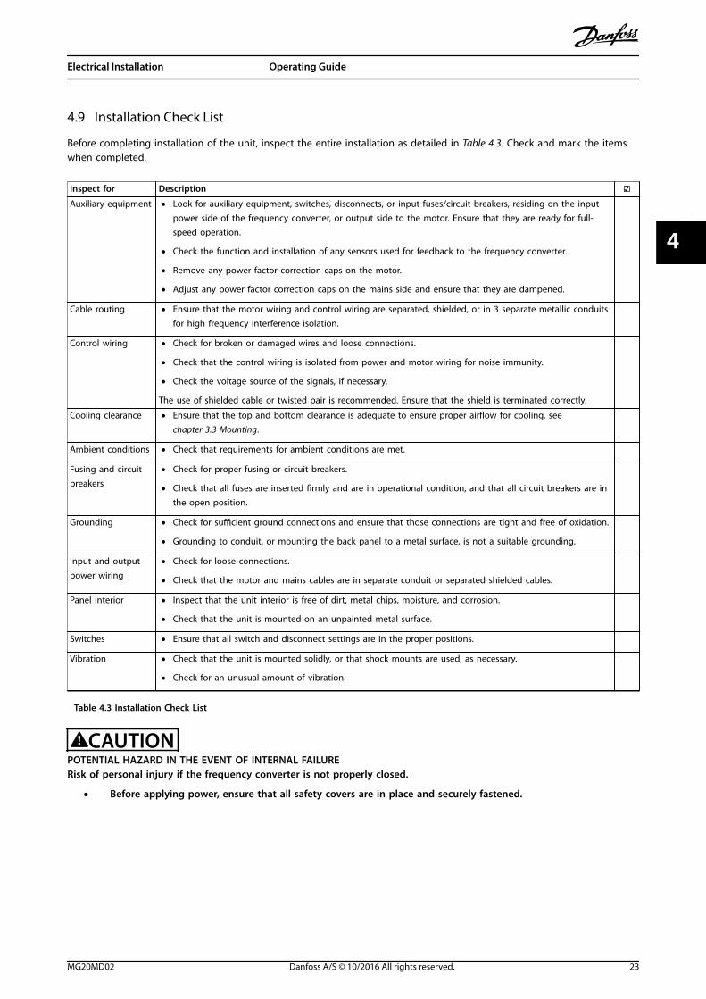
4.9 Installation Check List
Before completing installation of the unit, inspect the entire installation as detailed in Table 4.3. Check and mark the itemswhen completed.
Inspect for Description Auxiliary equipment • Look for auxiliary equipment, switches, disconnects, or input fuses/circuit breakers, residing on the input
power side of the frequency converter, or output side to the motor. Ensure that they are ready for full-speed operation.
• Check the function and installation of any sensors used for feedback to the frequency converter.
• Remove any power factor correction caps on the motor.
• Adjust any power factor correction caps on the mains side and ensure that they are dampened.
Cable routing • Ensure that the motor wiring and control wiring are separated, shielded, or in 3 separate metallic conduitsfor high frequency interference isolation.
Control wiring • Check for broken or damaged wires and loose connections.
• Check that the control wiring is isolated from power and motor wiring for noise immunity.
• Check the voltage source of the signals, if necessary.
The use of shielded cable or twisted pair is recommended. Ensure that the shield is terminated correctly.
Cooling clearance • Ensure that the top and bottom clearance is adequate to ensure proper airflow for cooling, see chapter 3.3 Mounting.
Ambient conditions • Check that requirements for ambient conditions are met.
Fusing and circuitbreakers
• Check for proper fusing or circuit breakers.
• Check that all fuses are inserted firmly and are in operational condition, and that all circuit breakers are inthe open position.
Grounding • Check for sufficient ground connections and ensure that those connections are tight and free of oxidation.
• Grounding to conduit, or mounting the back panel to a metal surface, is not a suitable grounding.
Input and outputpower wiring
• Check for loose connections.
• Check that the motor and mains cables are in separate conduit or separated shielded cables.
Panel interior • Inspect that the unit interior is free of dirt, metal chips, moisture, and corrosion.
• Check that the unit is mounted on an unpainted metal surface.
Switches • Ensure that all switch and disconnect settings are in the proper positions.
Vibration • Check that the unit is mounted solidly, or that shock mounts are used, as necessary.
• Check for an unusual amount of vibration.
Table 4.3 Installation Check List
CAUTIONPOTENTIAL HAZARD IN THE EVENT OF INTERNAL FAILURERisk of personal injury if the frequency converter is not properly closed.
• Before applying power, ensure that all safety covers are in place and securely fastened.
Electrical Installation Operating Guide
MG20MD02 Danfoss A/S © 10/2016 All rights reserved. 23
4 4

5 Commissioning
5.1 Safety Instructions
See chapter 2 Safety for general safety instructions.
WARNINGHIGH VOLTAGEFrequency converters contain high voltage whenconnected to AC mains input power. Failure to performinstallation, start-up, and maintenance by qualifiedpersonnel could result in death or serious injury.
• Installation, start-up, and maintenance must beperformed by qualified personnel only.
Before applying power:1. Close the cover properly.
2. Check that all cable glands are firmly tightened.
3. Ensure that input power to the unit is off andlocked out. Do not rely on the frequencyconverter disconnect switches for input powerisolation.
4. Verify that there is no voltage on input terminalsL1 (91), L2 (92), and L3 (93), phase-to-phase, andphase-to-ground.
5. Verify that there is no voltage on outputterminals 96 (U), 97 (V), and 98 (W), phase-to-phase, and phase-to-ground.
6. Confirm continuity of the motor by measuring Ωvalues on U–V (96–97), V–W (97–98), and W–U(98–96).
7. Check for proper grounding of the frequencyconverter and the motor.
8. Inspect the frequency converter for looseconnections on the terminals.
9. Confirm that the supply voltage matches thevoltage of the frequency converter and themotor.
5.2 Applying Power
Apply power to the frequency converter using thefollowing steps:
1. Confirm that the input voltage is balanced within3%. If not, correct the input voltage imbalancebefore proceeding. Repeat this procedure afterthe voltage correction.
2. Ensure that any optional equipment wiringmatches the installation application.
3. Ensure that all operator devices are in the OFFposition. Panel doors must be closed and coverssecurely fastened.
4. Apply power to the unit. Do not start thefrequency converter now. For units with adisconnect switch, turn it to the ON position toapply power to the frequency converter.
5.3 Local Control Panel Operation
The local control panel (LCP) is the combined display andkeypad on the front of the unit.
The LCP has several user functions:
• Start, stop, and control speed when in localcontrol.
• Show operational data, status, warnings, andcautions.
• Program frequency converter functions.
• Manually reset the frequency converter after afault when auto reset is inactive.
An optional numeric LCP (NLCP) is also available. The NLCPoperates in a manner similar to the LCP. See the productrelevant programming guide for details on use of the NLCP.
NOTICEFor commissioning via PC, install the MCT 10 Set-upSoftware. The software is available for download (basicversion) or for ordering (advanced version, code number130B1000). For more information and downloads, seewww.danfoss.com/BusinessAreas/DrivesSolutions/Software+MCT10/MCT10+Downloads.htm.
5.3.1 Graphic Local Control Panel Layout
The graphic local control panel (GLCP) is divided into 4functional groups (see Illustration 5.1).
A. Display area.
B. Display menu keys.
C. Navigation keys and indicator lights.
D. Operation keys and reset.
Commissioning VLT® AQUA Drive FC 202
24 Danfoss A/S © 10/2016 All rights reserved. MG20MD02
55

130B
D59
8.10
Autoon
ResetHandon
Off
StatusQuickMenu
MainMenu
AlarmLog
Back
CancelInfoOK
Status 1(1)36.4 kW
Auto Remote Ramping
0.000
On
Alarm
Warn.
A
7.83 A799 RPM
B
C
D
53.2 %
1
2
3
4
5
6
78
9
10
11
12
13
14
15
16
17
18 19 20 21
Illustration 5.1 GLCP
A. Display areaThe display area is activated when the frequency converterreceives power from the mains voltage, a DC bus terminal,or a 24 V DC external supply.
The information shown on the LCP can be customized foruser applications. Select options in the Quick Menu Q3-13Display Settings.
Display Parameter Default setting
1 Parameter 0-20 DisplayLine 1.1 Small
[1617] Speed [RPM]
2 Parameter 0-21 DisplayLine 1.2 Small
[1614] Motor Current
3 Parameter 0-22 DisplayLine 1.3 Small
[1610] Power [kW]
4 Parameter 0-23 DisplayLine 2 Large
[1613] Frequency
5 Parameter 0-24 DisplayLine 3 Large
[1602] Reference %
Table 5.1 Legend to Illustration 5.1, Display Area
B. Display menu keysMenu keys are used for menu access for parameter set-up,toggling through status display modes during normaloperation, and viewing fault log data.
Key Function
6 Status Shows operational information.
7 Quick Menu Allows access to programming parametersfor initial set-up instructions and manydetailed application instructions.
8 Main Menu Allows access to all programmingparameters.
9 Alarm Log Shows a list of current warnings, the last10 alarms, and the maintenance log.
Table 5.2 Legend to Illustration 5.1, Display Menu Keys
C. Navigation keys and indicator lights (LEDs)Navigation keys are used for programming functions andmoving the display cursor. The navigation keys alsoprovide speed control in local operation. There are also 3frequency converter status indicator lights in this area.
Key Function
10 Back Reverts to the previous step or list in themenu structure.
11 Cancel Cancels the last change or command as longas the display mode is not changed.
12 Info Press for a definition of the function beingshowed.
13 NavigationKeys
Press the navigation keys to move betweenitems in the menu.
14 OK Press to access parameter groups or toenable a selection.
Table 5.3 Legend to Illustration 5.1, Navigation Keys
Indicator Color Function
15 On Green The ON indicator light activateswhen the frequency converterreceives power from the mainsvoltage, a DC bus terminal, or a24 V external supply.
16 Warn Yellow When warning conditions are met,the yellow WARN indicator lightcomes on and text appears in thedisplay area identifying theproblem.
17 Alarm Red A fault condition causes the redalarm LED to flash and an alarmtext is shown.
Table 5.4 Legend to Illustration 5.1, Indicator Lights (LEDs)
Commissioning Operating Guide
MG20MD02 Danfoss A/S © 10/2016 All rights reserved. 25
5 5

D. Operation keys and resetOperation keys are at the bottom of the LCP.
Key Function
18 [Hand On] Starts the frequency converter in localcontrol.
• An external stop signal by control inputor serial communication overrides thelocal hand on.
19 Off Stops the motor but does not remove powerto the frequency converter.
20 [Auto On] Puts the system in remote operational mode.
• Responds to an external start commandby control terminals or serial communi-cation.
21 Reset Resets the frequency converter manuallyafter a fault has been cleared.
Table 5.5 Legend to Illustration 5.1, Operation Keys and Reset
NOTICEThe display contrast can be adjusted by pressing [Status]and the []/[] keys.
5.3.2 Parameter Settings
Establishing the correct programming for applicationsoften requires setting functions in several relatedparameters. Details for parameters are provided in chapter 9.2 Parameter Menu Structure.
Programming data is stored internally in the frequencyconverter.
• For back-up, upload data into the LCP memory.
• To download data to another frequencyconverter, connect the LCP to that unit anddownload the stored settings.
• Restoring factory default settings does notchange data stored in the LCP memory.
5.3.3 Uploading/Downloading Data to/fromthe LCP
1. Press [Off] to stop the motor before uploading ordownloading data.
2. Press [Main Menu], select parameter 0-50 LCP Copyand press [OK].
3. Select [1] All to LCP to upload data to the LCP orselect [2] All from LCP to download data from theLCP.
4. Press [OK]. A progress bar shows the uploading ordownloading progress.
5. Press [Hand On] or [Auto On] to return to normaloperation.
5.3.4 Changing Parameter Settings
Access and change parameter settings from the QuickMenu or from the Main Menu. The Quick Menu only givesaccess to a limited number of parameters.
1. Press [Quick Menu] or [Main Menu] on the LCP.
2. Press [] [] to browse through the parametergroups, press [OK] to select a parameter group.
3. Press [] [] to browse through the parameters,press [OK] to select a parameter.
4. Press [] [] to change the value of a parametersetting.
5. Press [] [] to shift digit when a decimalparameter is in the editing state.
6. Press [OK] to accept the change.
7. Press either [Back] twice to enter Status, or press[Main Menu] once to enter the Main Menu.
View changesQuick Menu Q5 - Changes Made lists all parameterschanged from default settings.
• The list only shows parameters, which arechanged in the current edit set-up.
• Parameters, which were reset to default values,are not listed.
• The message Empty indicates that no parametersare changed.
5.3.5 Restoring Default Settings
NOTICERisk of losing programming, motor data, localization, andmonitoring records by restoration of default settings. Toprovide a back-up, upload data to the LCP before initiali-zation.
Restoring the default parameter settings is done by initiali-zation of the frequency converter. Initialization is carriedout through parameter 14-22 Operation Mode(recommended) or manually.
• Initialization using parameter 14-22 OperationMode does not reset frequency converter settingssuch as hours run, serial communicationselections, personal menu settings, fault log,alarm log, and other monitoring functions.
• Manual initialization erases all motor,programming, localization, and monitoring dataand restores factory default settings.
Commissioning VLT® AQUA Drive FC 202
26 Danfoss A/S © 10/2016 All rights reserved. MG20MD02
55

Recommended initialization procedure viaparameter 14-22 Operation Mode
1. Press [Main Menu] twice to access parameters.
2. Scroll to parameter 14-22 Operation Mode andpress [OK].
3. Scroll to [2] initialization and press [OK].
4. Remove power to the unit and wait for thedisplay to turn off.
5. Apply power to the unit.
Default parameter settings are restored during start-up.The start-up may take slightly longer than normal.
6. Alarm 80, Drive initialized to default value is shown.
7. Press [Reset] to return to operating mode.
Manual initialization procedure
1. Remove power to the unit and wait for thedisplay to turn off.
2. Press and hold [Status], [Main Menu], and [OK] atthe same time while applying power to the unit(approximately 5 s or until audible click and fanstarts).
Factory default parameter settings are restored duringstart-up. The start-up may take slightly longer than usual.
Manual initialization does not reset the followingfrequency converter information:
• Parameter 15-00 Operating hours.
• Parameter 15-03 Power Up's.
• Parameter 15-04 Over Temp's.
• Parameter 15-05 Over Volt's.
5.4 Basic Programming
5.4.1 Commissioning with SmartStart
The SmartStart wizard enables fast configuration of basicmotor and application parameters.
• SmartStart starts automatically at first power-upor after initialization of the frequency converter.
• Follow the on-screen instructions to complete thecommissioning of the frequency converter.Always reactivate SmartStart by selecting QuickMenu Q4 - SmartStart.
• For commissioning without use of the SmartStartwizard, refer to chapter 5.4.2 Commissioning via[Main Menu] or the programming guide.
NOTICEMotor data is required for the SmartStart set-up. Therequired data is normally available on the motornameplate.
The SmartStart configures the frequency converter in 3phases, each consisting of several steps, see Table 5.6.
Phase Action
1 Basic Programming Perform the programming
2 Application Section
Select and programappropriate application:
• Single pump/motor.
• Motor alternation.
• Basic cascade control.
• Master/slave.
3 Water and Pump FeaturesGo to water and pumpdedicated parameters.
Table 5.6 SmartStart, Setup in 3 Phases
5.4.2 Commissioning via [Main Menu]
Recommended parameter settings are intended for start-up and check-out purposes. Application settings may vary.
Enter data with power ON, but before operating thefrequency converter.
1. Press [Main Menu] on the LCP.
2. Press the navigation keys to scroll to parametergroup 0-** Operation/Display and press [OK].
130B
P066
.10
1107 RPM
0 - ** Operation/Display
1 - ** Load/Motor
2 - ** Brakes
3 - ** Reference / Ramps
3.84 A 1 (1)
Main menu
Illustration 5.2 Main Menu
3. Press the navigation keys to scroll to parametergroup 0-0* Basic Settings and press [OK].
0-**Operation / Display0.0%
0-0* Basic Settings0-1* Set-up Operations0-2* LCP Display0-3* LCP Custom Readout
0.00A 1(1)
130B
P087
.10
Illustration 5.3 Operation/Display
Commissioning Operating Guide
MG20MD02 Danfoss A/S © 10/2016 All rights reserved. 27
5 5
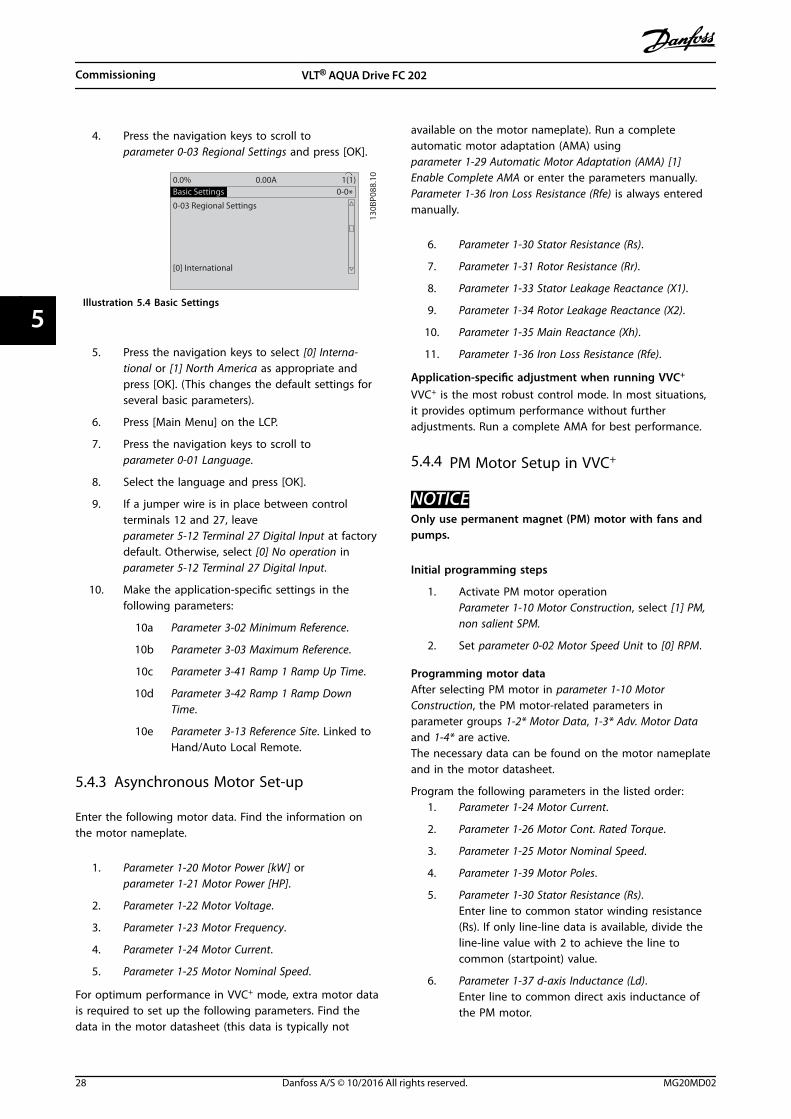
4. Press the navigation keys to scroll toparameter 0-03 Regional Settings and press [OK].
0-0*Basic Settings0.0%
0-03 Regional Settings
[0] International
0.00A 1(1)
130B
P088
.10
Illustration 5.4 Basic Settings
5. Press the navigation keys to select [0] Interna-tional or [1] North America as appropriate andpress [OK]. (This changes the default settings forseveral basic parameters).
6. Press [Main Menu] on the LCP.
7. Press the navigation keys to scroll toparameter 0-01 Language.
8. Select the language and press [OK].
9. If a jumper wire is in place between controlterminals 12 and 27, leaveparameter 5-12 Terminal 27 Digital Input at factorydefault. Otherwise, select [0] No operation inparameter 5-12 Terminal 27 Digital Input.
10. Make the application-specific settings in thefollowing parameters:
10a Parameter 3-02 Minimum Reference.
10b Parameter 3-03 Maximum Reference.
10c Parameter 3-41 Ramp 1 Ramp Up Time.
10d Parameter 3-42 Ramp 1 Ramp DownTime.
10e Parameter 3-13 Reference Site. Linked toHand/Auto Local Remote.
5.4.3 Asynchronous Motor Set-up
Enter the following motor data. Find the information onthe motor nameplate.
1. Parameter 1-20 Motor Power [kW] orparameter 1-21 Motor Power [HP].
2. Parameter 1-22 Motor Voltage.
3. Parameter 1-23 Motor Frequency.
4. Parameter 1-24 Motor Current.
5. Parameter 1-25 Motor Nominal Speed.
For optimum performance in VVC+ mode, extra motor datais required to set up the following parameters. Find thedata in the motor datasheet (this data is typically not
available on the motor nameplate). Run a completeautomatic motor adaptation (AMA) usingparameter 1-29 Automatic Motor Adaptation (AMA) [1]Enable Complete AMA or enter the parameters manually.Parameter 1-36 Iron Loss Resistance (Rfe) is always enteredmanually.
6. Parameter 1-30 Stator Resistance (Rs).
7. Parameter 1-31 Rotor Resistance (Rr).
8. Parameter 1-33 Stator Leakage Reactance (X1).
9. Parameter 1-34 Rotor Leakage Reactance (X2).
10. Parameter 1-35 Main Reactance (Xh).
11. Parameter 1-36 Iron Loss Resistance (Rfe).
Application-specific adjustment when running VVC+
VVC+ is the most robust control mode. In most situations,it provides optimum performance without furtheradjustments. Run a complete AMA for best performance.
5.4.4 PM Motor Setup in VVC+
NOTICEOnly use permanent magnet (PM) motor with fans andpumps.
Initial programming steps
1. Activate PM motor operationParameter 1-10 Motor Construction, select [1] PM,non salient SPM.
2. Set parameter 0-02 Motor Speed Unit to [0] RPM.
Programming motor dataAfter selecting PM motor in parameter 1-10 MotorConstruction, the PM motor-related parameters inparameter groups 1-2* Motor Data, 1-3* Adv. Motor Dataand 1-4* are active.The necessary data can be found on the motor nameplateand in the motor datasheet.
Program the following parameters in the listed order:1. Parameter 1-24 Motor Current.
2. Parameter 1-26 Motor Cont. Rated Torque.
3. Parameter 1-25 Motor Nominal Speed.
4. Parameter 1-39 Motor Poles.
5. Parameter 1-30 Stator Resistance (Rs).Enter line to common stator winding resistance(Rs). If only line-line data is available, divide theline-line value with 2 to achieve the line tocommon (startpoint) value.
6. Parameter 1-37 d-axis Inductance (Ld).Enter line to common direct axis inductance ofthe PM motor.
Commissioning VLT® AQUA Drive FC 202
28 Danfoss A/S © 10/2016 All rights reserved. MG20MD02
55

If only line-line data is available, divide the line-line value by 2 to achieve the line-common(startpoint) value.
7. Parameter 1-40 Back EMF at 1000 RPM.Enter line-to-line back EMF of the PM motor at1000 RPM mechanical speed (RMS value). BackEMF is the voltage generated by a PM motorwhen no frequency converter is connected andthe shaft is turned externally. Back EMF isnormally specified for nominal motor speed or for1000 RPM measured between 2 lines. If the valueis not available for a motor speed of 1000 RPM,calculate the correct value as follows: If back EMFis for example 320 V at 1800 RPM, it can becalculated at 1000 RPM as follows: Back EMF =(Voltage / RPM)*1000 = (320/1800)*1000 = 178.This is the value that must be programmed forparameter 1-40 Back EMF at 1000 RPM.
Test motor operation
1. Start the motor at low speed (100–200 RPM). Ifthe motor does not turn, check installation,general programming, and motor data.
2. Check if the start function in parameter 1-70 PMStart Mode fits the application requirements.
Rotor detectionThis function is the recommended choice for applicationswhere the motor starts from standstill, for example pumpsor conveyors. On some motors, a sound is heard when theimpulse is sent out. This does not harm the motor.
ParkingThis function is the recommended choice for applicationswhere the motor is rotating at slow speed, for examplewindmilling in fan applications. Parameter 2-06 ParkingCurrent and parameter 2-07 Parking Time can be adjusted.Increase the factory setting of these parameters forapplications with high inertia.
Start the motor at nominal speed. If the application doesnot run well, check the VVC+ PM settings. Recommendedsettings in different applications can be found in Table 5.7.
Application Settings
Low inertia applicationsILoad/IMotor <5
Parameter 1-17 Voltage filter timeconst. to be increased by factor 5–10.Parameter 1-14 Damping Gain shouldbe reduced.Parameter 1-66 Min. Current at LowSpeed should be reduced (<100%).
Low inertia applications50>ILoad/IMotor >5
Keep calculated values.
High inertia applicationsILoad/IMotor > 50
Parameter 1-14 Damping Gain,parameter 1-15 Low Speed Filter TimeConst., and parameter 1-16 HighSpeed Filter Time Const. should beincreased.
High load at low speed<30% (rated speed)
Parameter 1-17 Voltage filter timeconst. should be increased.Parameter 1-66 Min. Current at LowSpeed should be increased (>100%for a prolonged time can overheatthe motor).
Table 5.7 Recommended Settings in Different Applications
If the motor starts oscillating at a certain speed, increaseparameter 1-14 Damping Gain. Increase the value in smallsteps. Depending on the motor, a good value for thisparameter can be 10% or 100% higher than the defaultvalue.
The starting torque can be adjusted in parameter 1-66 Min.Current at Low Speed. 100% provides nominal torque asstarting torque.
5.4.5 SynRM Motor Set-up with VVC+
This section describes how to set up a SynRM motor withVVC+.
NOTICEThe SmartStart wizard covers the basic configuration ofSynRM motors.
Initial programming stepsTo activate SynRM motor operation, select [5] Sync.Reluctance in parameter 1-10 Motor Construction.
Programming motor dataAfter performing the initial programming steps, the SynRMmotor-related parameters in parameter groups 1-2* MotorData, 1-3* Adv. Motor Data, and 1-4* Adv. Motor Data II areactive.
Use the motor nameplate data and the motor datasheet toprogram the following parameters in the order listed:
Commissioning Operating Guide
MG20MD02 Danfoss A/S © 10/2016 All rights reserved. 29
5 5

1. Parameter 1-23 Motor Frequency.
2. Parameter 1-24 Motor Current.
3. Parameter 1-25 Motor Nominal Speed.
4. Parameter 1-26 Motor Cont. Rated Torque.
Run a complete AMA using parameter 1-29 AutomaticMotor Adaptation (AMA) [1] Enable Complete AMA or enterthe following parameters manually:
1. Parameter 1-30 Stator Resistance (Rs).
2. Parameter 1-37 d-axis Inductance (Ld).
3. Parameter 1-44 d-axis Inductance Sat. (LdSat).
4. Parameter 1-45 q-axis Inductance Sat. (LqSat).
5. Parameter 1-48 Inductance Sat. Point.
Application-specific adjustmentsStart the motor at nominal speed. If the application doesnot run well, check the VVC+ SynRM settings. Table 5.8provides application-specific recommendations:
Application Settings
Low-inertia applicationsILoad/IMotor<5
Increase parameter 1-17 Voltage filtertime const. by factor 5–10.Reduce parameter 1-14 DampingGain.Reduce parameter 1-66 Min. Currentat Low Speed (<100%).
Low-inertia applications50>ILoad/IMotor>5
Keep the default values.
High-inertia applicationsILoad/IMotor>50
Increase parameter 1-14 DampingGain, parameter 1-15 Low Speed FilterTime Const., and parameter 1-16 HighSpeed Filter Time Const.
High-load at low speed<30% (rated speed)
Increase parameter 1-17 Voltage filtertime const.Increase parameter 1-66 Min. Currentat Low Speed to adjust the startingtorque. 100% current providesnominal torque as starting torque.Working at a current level higherthan 100% for a prolonged time cancause the motor to overheat.
Application Settings
Dynamic applications Increase parameter 14-41 AEOMinimum Magnetisation for highlydynamic applications. Adjustingparameter 14-41 AEO MinimumMagnetisation ensures a goodbalance between energy efficiencyand dynamics. Adjustparameter 14-42 Minimum AEOFrequency to specify the minimumfrequency at which the frequencyconverter should use minimummagnetization.
Motor sizes less than 18kW (24 hp)
Avoid short ramp-down times.
Table 5.8 Recommendations for Various Applications
If the motor starts oscillating at a certain speed, increaseparameter 1-14 Damping Gain. Increase the damping gainvalue in small steps. Depending on the motor, thisparameter can be set to 10–100% higher than the defaultvalue.
5.4.6 Automatic Energy Optimization (AEO)
NOTICEAEO is not relevant for permanent magnet motors.
AEO is a procedure which minimizes voltage to the motor,as a result of that reducing energy consumption, heat, andnoise.
To activate AEO, set parameter 1-03 Torque Characteristics to[2] Auto Energy Optim. CT or [3] Auto Energy Optim. VT.
5.4.7 Automatic Motor Adaptation (AMA)
AMA is a procedure which optimizes compatibilitybetween the frequency converter and the motor.
• The frequency converter builds a mathematicalmodel of the motor for regulating output motorcurrent. The procedure also tests the input phasebalance of electrical power. It compares themotor characteristics with the entered nameplatedata.
• The motor shaft does not turn and no harm isdone to the motor while running the AMA.
• Some motors may be unable to run the completeversion of the test. In that case, select [2] Enablereduced AMA.
• If an output filter is connected to the motor,select [2] Enable reduced AMA.
Commissioning VLT® AQUA Drive FC 202
30 Danfoss A/S © 10/2016 All rights reserved. MG20MD02
55

• If warnings or alarms occur, see chapter 7.4 List ofWarnings and Alarms.
• Run this procedure on a cold motor for bestresults.
To run AMA1. Press [Main Menu] to access parameters.
2. Scroll to parameter group 1-** Load and Motor andpress [OK].
3. Scroll to parameter group 1-2* Motor Data andpress [OK].
4. Scroll to parameter 1-29 Automatic MotorAdaptation (AMA) and press [OK].
5. Select [1] Enable complete AMA and press [OK].
6. Follow the on-screen instructions.
7. The test runs automatically and indicates when itis complete.
8. The advanced motor data is entered in parametergroup 1-3* Adv. Motor Data.
5.5 Checking Motor Rotation
NOTICERisk of damage to pumps/compressors caused by motorrunning in wrong direction. Before running thefrequency converter, check the motor rotation.
The motor runs briefly at 5 Hz or the minimum frequencyset in parameter 4-12 Motor Speed Low Limit [Hz].
1. Press [Main Menu].
2. Scroll to parameter 1-28 Motor Rotation Check andpress [OK].
3. Scroll to [1] Enable.
The following text appears: Note! Motor may run in wrongdirection.
4. Press [OK].
5. Follow the on-screen instructions.
NOTICETo change the direction of rotation, remove power to thefrequency converter and wait for power to discharge.Reverse the connection of any 2 of the 3 motor wires onthe motor or frequency converter side of the connection.
5.6 Local-control Test
1. Press [Hand On] to provide a local start commandto the frequency converter.
2. Accelerate the frequency converter by pressing[] to full speed. Moving the cursor left of thedecimal point provides quicker input changes.
3. Note any acceleration problems.
4. Press [Off]. Note any deceleration problems.
If acceleration or deceleration problems occur, see chapter 7.5 Troubleshooting. See chapter 7.4 List of Warningsand Alarms for resetting the frequency converter after atrip.
5.7 System Start-up
The procedure in this section requires wiring andapplication programming to be completed. The followingprocedure is recommended after application set-up iscompleted.
1. Press [Auto On].
2. Apply an external run command.
3. Adjust the speed reference throughout the speedrange.
4. Remove the external run command.
5. Check the sound and vibration levels of themotor to ensure that the system is working asintended.
If warnings or alarms occur, see chapter 7.3 Warning andAlarm Types or chapter 7.4 List of Warnings and Alarms.
Commissioning Operating Guide
MG20MD02 Danfoss A/S © 10/2016 All rights reserved. 31
5 5
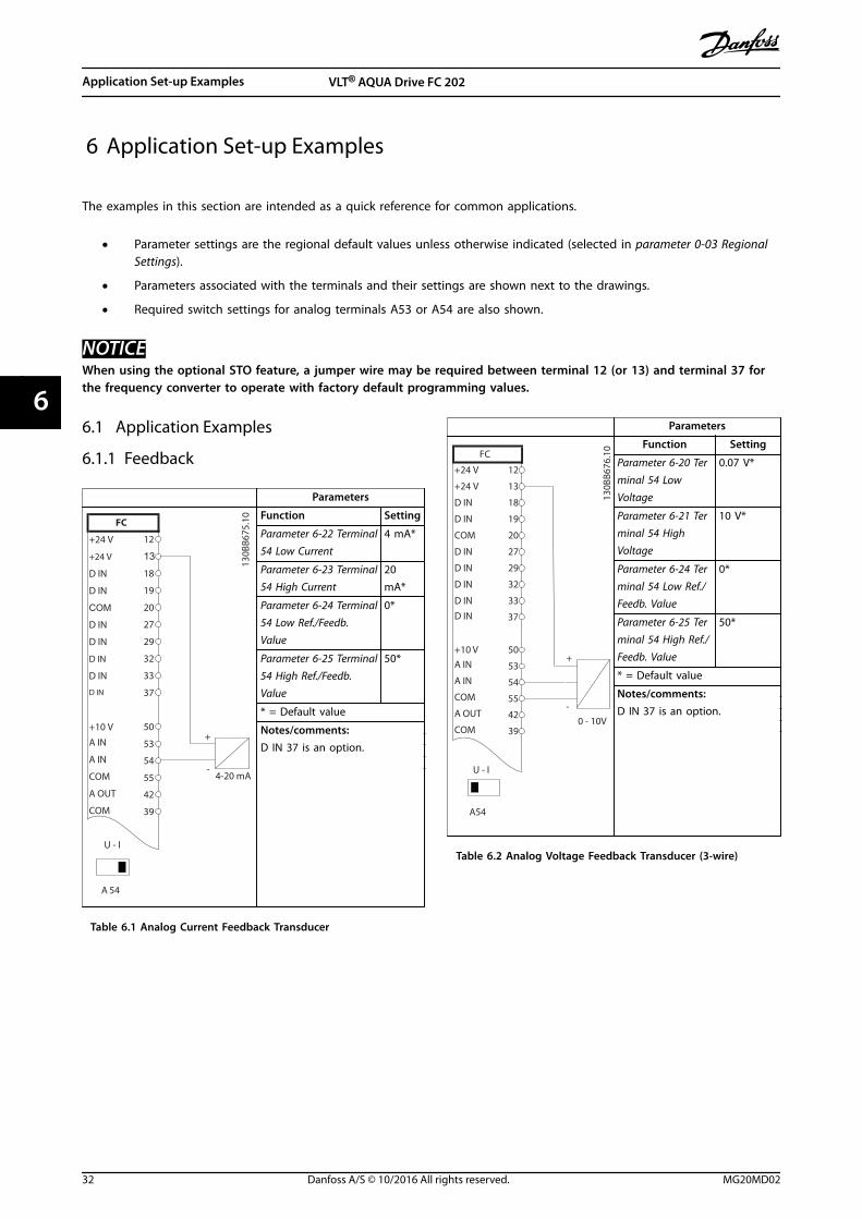
6 Application Set-up Examples
The examples in this section are intended as a quick reference for common applications.
• Parameter settings are the regional default values unless otherwise indicated (selected in parameter 0-03 RegionalSettings).
• Parameters associated with the terminals and their settings are shown next to the drawings.
• Required switch settings for analog terminals A53 or A54 are also shown.
NOTICEWhen using the optional STO feature, a jumper wire may be required between terminal 12 (or 13) and terminal 37 forthe frequency converter to operate with factory default programming values.
6.1 Application Examples
6.1.1 Feedback
Parameters
FC
4-20 mA
+24 V
+24 V
D IN
D IN
D IN
COM
D IN
D IN
D IN
D IN
+10 V
A IN
A IN
COM
A OUT
COM
12
13
18
19
20
27
29
32
33
37
50
53
54
55
42
39
A 54
U - I
+
-
130B
B675
.10 Function Setting
Parameter 6-22 Terminal54 Low Current
4 mA*
Parameter 6-23 Terminal54 High Current
20mA*
Parameter 6-24 Terminal54 Low Ref./Feedb.Value
0*
Parameter 6-25 Terminal54 High Ref./Feedb.Value
50*
* = Default value
Notes/comments:D IN 37 is an option.
Table 6.1 Analog Current Feedback Transducer
Parameters
FC
+24 V
+24 V
D IN
D IN
D IN
COM
D IN
D IN
D IN
D IN
+10 V
A IN
A IN
COM
A OUT
COM
12
13
18
19
20
27
29
32
33
37
50
53
54
55
42
39
A54
U - I
0 - 10V
+
-
130B
B676
.10 Function Setting
Parameter 6-20 Terminal 54 LowVoltage
0.07 V*
Parameter 6-21 Terminal 54 HighVoltage
10 V*
Parameter 6-24 Terminal 54 Low Ref./Feedb. Value
0*
Parameter 6-25 Terminal 54 High Ref./Feedb. Value
50*
* = Default value
Notes/comments:D IN 37 is an option.
Table 6.2 Analog Voltage Feedback Transducer (3-wire)
Application Set-up Examples VLT® AQUA Drive FC 202
32 Danfoss A/S © 10/2016 All rights reserved. MG20MD02
66

Parameters
FC
+24 V
+24 V
D IN
D IN
D IN
COM
D IN
D IN
D IN
D IN
+10 V
A IN
A IN
COM
A OUT
COM
12
13
18
19
20
27
29
32
33
37
50
53
54
55
42
39
A54
U - I
0 - 10V
+
-
130B
B677
.10 Function Setting
Parameter 6-20 Terminal 54 LowVoltage
0.07 V*
Parameter 6-21 Terminal 54 HighVoltage
10 V*
Parameter 6-24 Terminal 54 Low Ref./Feedb. Value
0*
Parameter 6-25 Terminal 54 High Ref./Feedb. Value
50*
* = Default value
Notes/comments:D IN 37 is an option.
Table 6.3 Analog Voltage Feedback Transducer (4-wire)
6.1.2 Speed
Parameters
FC
+24 V
+24 V
D IN
D IN
D IN
COM
D IN
D IN
D IN
D IN
+10 V
A IN
A IN
COM
A OUT
COM
12
13
18
19
20
27
29
32
33
37
50
53
54
55
42
39
A53
U - I
-10 - +10V
+
-
130B
B926
.10 Function Setting
Parameter 6-10 Terminal 53 LowVoltage
0.07 V*
Parameter 6-11 Terminal 53 HighVoltage
10 V*
Parameter 6-14 Terminal 53 Low Ref./Feedb. Value
0 Hz
Parameter 6-15 Terminal 53 High Ref./Feedb. Value
50 Hz
* = Default value
Notes/comments:D IN 37 is an option.
Table 6.4 Analog Speed Reference (Voltage)
Parameters
130B
B927
.10
FC
+24 V
+24 V
D IN
D IN
D IN
COM
D IN
D IN
D IN
D IN
+10 VA IN
A IN
COM
A OUT
COM
12
13
18
19
20
27
29
32
33
37
50
53
54
55
42
39
A53
U - I
4 - 20mA
+
-
Function Setting
Parameter 6-12 Terminal 53 LowCurrent
4 mA*
Parameter 6-13 Terminal 53 HighCurrent
20 mA*
Parameter 6-14 Terminal 53 Low Ref./Feedb. Value
0 Hz
Parameter 6-15 Terminal 53 High Ref./Feedb. Value
50 Hz
* = Default value
Notes/comments:D IN 37 is an option.
Table 6.5 Analog Speed Reference (Current)
Parameters
FC
+24 V
+24 V
D IN
D IN
D IN
COM
D IN
D IN
D IN
D IN
+10 V
A IN
A IN
COM
A OUT
COM
12
13
18
19
20
27
29
32
33
37
50
53
54
55
42
39
A53
U - I
≈ 5kΩ
130B
B683
.10 Function Setting
Parameter 6-10 Terminal 53 LowVoltage
0.07 V*
Parameter 6-11 Terminal 53 HighVoltage
10 V*
Parameter 6-14 Terminal 53 Low Ref./Feedb. Value
0 Hz
Parameter 6-15 Terminal 53 High Ref./Feedb. Value
50 Hz
* = Default value
Notes/comments:D IN 37 is an option.
Table 6.6 Speed Reference (Using a Manual Potentiometer)
Application Set-up Examples Operating Guide
MG20MD02 Danfoss A/S © 10/2016 All rights reserved. 33
6 6

6.1.3 Run/Stop
Parameters
FC
+24 V
+24 V
D IN
D IN
D IN
COM
D IN
D IN
D IN
D IN
+10 V
A IN
A IN
COM
A OUT
COM
12
13
18
19
20
27
29
32
33
37
50
53
54
55
42
39
130B
B680
.10 Function Setting
Parameter 5-10 Terminal 18Digital Input
[8] Start*
Parameter 5-12 Terminal 27Digital Input
[7] Externalinterlock
* = Default value
Notes/comments:D IN 37 is an option.
Table 6.7 Run/Stop Command with External Interlock
Parameters
FC
+24 V
+24 V
D IN
D IN
D IN
COM
D IN
D IN
D IN
D IN
+10 V
A IN
A IN
COM
A OUT
COM
R1R2
12
13
18
19
20
27
29
32
33
37
50
53
54
55
42
39
01
02
03
04
05
06
130B
B681
.10 Function Setting
Parameter 5-10 Terminal 18Digital Input
[8] Start*
Parameter 5-12 Terminal 27Digital Input
[7] Externalinterlock
* = Default value
Notes/comments:If parameter 5-12 Terminal 27Digital Input is set to [0] Nooperation, a jumper wire toterminal 27 is not needed.D IN 37 is an option.
Table 6.8 Run/Stop Command without External Interlock
Parameters
FC
+24 V
+24 V
D IN
D IN
D IN
COM
D IN
D IN
D IN
D IN
+10 V
A IN
A IN
COM
A OUT
COMR1
R2
12
13
18
19
20
27
29
32
33
37
50
53
54
55
42
39
01
02
03
04
05
06
130B
B684
.10 Function Setting
Parameter 5-10 Terminal 18Digital Input
[8] Start*
Parameter 5-11 Terminal 19Digital Input
[52] RunPermissive
Parameter 5-12 Terminal 27Digital Input
[7] Externalinterlock
Parameter 5-40 Function Relay
[167] Startcommandact.
* = Default value
Notes/comments:D IN 37 is an option.
Table 6.9 Run Permissive
6.1.4 External Alarm Reset
Parameters
FC
+24 V
+24 V
D IN
D IN
D IN
COM
D IN
D IN
D IN
D IN
+10 V
A IN
A IN
COM
A OUT
COM
12
13
18
19
20
27
29
32
33
37
50
53
54
55
42
39
130B
B682
.10 Function Setting
Parameter 5-11 Terminal 19Digital Input
[1] Reset
* = Default value
Notes/comments:D IN 37 is an option.
Table 6.10 External Alarm Reset
Application Set-up Examples VLT® AQUA Drive FC 202
34 Danfoss A/S © 10/2016 All rights reserved. MG20MD02
66

6.1.5 RS485
Parameters
FC
+24 V
+24 V
D IN
D IN
D IN
COM
D IN
D IN
D IN
D IN
+10 V
A IN
A IN
COM
A OUT
COM
R1R2
12
13
18
19
20
27
29
32
33
37
50
53
54
55
42
39
01
02
03
04
05
06
-
616869
RS-485
+
130B
B685
.10 Function Setting
Parameter 8-30 Protocol FC*
Parameter 8-31 Address
1*
Parameter 8-32 Baud Rate
9600*
* = Default value
Notes/comments:Select protocol, address, andbaud rate in the above-mentioned parameters.D IN 37 is an option.
Table 6.11 RS485 Network Connection
6.1.6 Motor Thermistor
CAUTIONTHERMISTOR INSULATIONRisk of personal injury or equipment damage.
• Use only thermistors with reinforced or doubleinsulation to meet PELV insulationrequirements.
Parameters
130B
B686
.12
VLT
+24 V
+24 V
D IN
D IN
D IN
COM
D IN
D IN
D IN
+10 VA IN
A IN
COM
A OUT
COM
12
13
18
19
20
27
29
32
33
50
53
54
55
42
39
A53
U - I
D IN 37
Function Setting
Parameter 1-90 Motor ThermalProtection
[2] Thermistortrip
Parameter 1-93 Thermistor Source
[1] Analoginput 53
* = Default value
Notes/comments:If only a warning is required,set parameter 1-90 MotorThermal Protection to [1]Thermistor warning.D IN 37 is an option.
Table 6.12 Motor Thermistor
Application Set-up Examples Operating Guide
MG20MD02 Danfoss A/S © 10/2016 All rights reserved. 35
6 6

7 Maintenance, Diagnostics, and Troubleshooting
This chapter includes:• Maintenance and service guidelines.
• Status messages.
• Warnings and alarms.
• Basic troubleshooting.
7.1 Maintenance and Service
Under normal operating conditions and load profiles, thefrequency converter is maintenance-free throughout itsdesigned lifetime. To prevent breakdown, danger, anddamage, examine the frequency converter at regularintervals depending on the operating conditions. Replaceworn or damaged parts with original spare parts orstandard parts. For service and support, contact the localDanfoss supplier.
WARNINGUNINTENDED STARTWhen the frequency converter is connected to AC mains,DC supply, or load sharing, the motor may start at anytime. Unintended start during programming, service, orrepair work can result in death, serious injury, orproperty damage. The motor can start via an externalswitch, a fieldbus command, an input reference signalfrom the LCP or LOP, via remote operation using MCT 10Set-up Software, or after a cleared fault condition.
7.2 Status Messages
When the frequency converter is in Status mode, statusmessages are generated automatically and appear in thebottom line of the display (see Illustration 7.1).
Status799RPM 7.83A 36.4kW
0.000
53.2%
1(1)
AutoHandO
RemoteLocal
RampingStopRunningJogging...Stand by
130B
B037
.11
1 2 3
1 Operating mode (see Table 7.1)
2 Reference site (see Table 7.2)
3 Operation status (see Table 7.3)
Illustration 7.1 Status Display
Table 7.1 to Table 7.3 describe the status messages shown.
Off The frequency converter does not react to anycontrol signal until [Auto On] or [Hand On] ispressed.
Auto On The frequency converter is controlled from thecontrol terminals and/or the serial communi-cation.
Hand On Control the frequency converter via thenavigation keys on the LCP. Stop commands,reset, reversing, DC brake, and other signalsapplied to the control terminals override localcontrol.
Table 7.1 Operating Mode
Remote The speed reference is given from externalsignals, serial communication, or internalpreset references.
Local The frequency converter uses [Hand On]control or reference values from the LCP.
Table 7.2 Reference Site
AC Brake [2] AC brake is selected in parameter 2-10 BrakeFunction. The AC brake overmagnetizes themotor to achieve a controlled slow down.
AMA finish OK AMA was carried out successfully.
AMA ready AMA is ready to start. Press [Hand On] to start.
AMA running AMA process is in progress.
Braking The brake chopper is in operation. Generativeenergy is absorbed by the brake resistor.
Maintenance, Diagnostics, a... VLT® AQUA Drive FC 202
36 Danfoss A/S © 10/2016 All rights reserved. MG20MD02
77

Braking max. The brake chopper is in operation. The powerlimit for the brake resistor defined inparameter 2-12 Brake Power Limit (kW) hasbeen reached.
Coast • [2] Coast inverse was selected as a functionfor a digital input (parameter group 5-1*Digital Inputs). The corresponding terminalis not connected.
• Coast activated by serial communication.
Ctrl. ramp-down [1] Control Ramp-down was selected inparameter 14-10 Mains Failure.
• The mains voltage is below the value setin parameter 14-11 Mains Voltage at MainsFault at mains fault.
• The frequency converter ramps down themotor using a controlled ramp down.
Current High The frequency converter output current isabove the limit set in parameter 4-51 WarningCurrent High.
Current Low The frequency converter output current isbelow the limit set in parameter 4-52 WarningSpeed Low.
DC Hold [1] DC hold is selected inparameter 1-80 Function at Stop and a stopcommand is active. The motor is held by a DCcurrent set in parameter 2-00 DC Hold/PreheatCurrent.
DC Stop The motor is held with a DC current(parameter 2-01 DC Brake Current) for aspecified time (parameter 2-02 DC BrakingTime).
• The DC brake cut-in speed is reached inparameter 2-03 DC Brake Cut In Speed [RPM]and a stop command is active.
• [5] DC-brake inverse is selected as afunction for a digital input (parametergroup 5-1* Digital Inputs). Thecorresponding terminal is not active.
• The DC brake is activated via serialcommunication.
Feedback high The sum of all active feedbacks is above thefeedback limit set in parameter 4-57 WarningFeedback High.
Feedback low The sum of all active feedbacks is below thefeedback limit set in parameter 4-56 WarningFeedback Low.
Freeze output The remote reference is active, which holdsthe present speed.
• [20] Freeze output is selected as a functionfor a digital input (parameter group 5-1*Digital Inputs). The corresponding terminalis active. Speed control is only possible viathe terminal options [21] Speed up and [22]Speed down.
• Hold ramp is activated via serial communi-cation.
Freeze outputrequest
A freeze output command was given, but themotor remains stopped until a run permissivesignal is received.
Freeze ref. [19] Freeze reference is selected as a functionfor a digital input (parameter group 5-1* DigitalInputs). The corresponding terminal is active.The frequency converter saves the actualreference. Changing the reference is now onlypossible via terminal options [21] Speed upand [22] Speed down.
Jog request A jog command was given, but the motorremains stopped until a run permissive signalis received via a digital input.
Jogging The motor is running as programmed inparameter 3-19 Jog Speed [RPM].
• [14] Jog was selected as a function for adigital input (parameter group 5-1* DigitalInputs). The corresponding terminal (forexample, terminal 29) is active.
• The jog function is activated via the serialcommunication.
• The jog function is selected as a reactionfor a monitoring function (for example, forthe no signal function). The monitoringfunction is active.
Motor check In parameter 1-80 Function at Stop, [2] MotorCheck is selected. A stop command is active.To ensure that a motor is connected to thefrequency converter, a permanent test currentis applied to the motor.
OVC control Overvoltage control is activated viaparameter 2-17 Over-voltage Control, [2]Enabled. The connected motor supplies thefrequency converter with generative energy.The overvoltage control adjusts the V/Hz ratioto run the motor in controlled mode and toprevent the frequency converter from tripping.
PowerUnit Off (Only frequency converters with a 24 Vexternal supply installed).Mains supply to the frequency converter wasremoved, and the control card is supplied bythe external 24 V.
Maintenance, Diagnostics, a... Operating Guide
MG20MD02 Danfoss A/S © 10/2016 All rights reserved. 37
7 7

Protection md Protection mode is active. The unit detected acritical status (overcurrent or overvoltage).
• To avoid tripping, switching frequency isreduced to 4 kHz.
• If possible, protection mode ends afterapproximately 10 s.
• Protection mode can be restricted inparameter 14-26 Trip Delay at Inverter Fault.
Qstop The motor is decelerating usingparameter 3-81 Quick Stop Ramp Time.
• [4] Quick stop inverse is selected as afunction for a digital input (parametergroup 5-1* Digital Inputs). Thecorresponding terminal is not active.
• The quick stop function is activated viaserial communication.
Ramping The motor is accelerating/decelerating usingthe active ramp up/down. The reference, alimit value, or a standstill is not yet reached.
Ref. high The sum of all active references is above thereference limit set in parameter 4-55 WarningReference High.
Ref. low The sum of all active references is below thereference limit set in parameter 4-54 WarningReference Low.
Run on ref. The frequency converter is running in thereference range. The feedback value matchesthe setpoint value.
Run request A start command was given, but the motorremains stopped until a run permissive signalis received via digital input.
Running The frequency converter drives the motor.
Sleep Mode The energy-saving function is enabled. Themotor has stopped, but restarts automaticallywhen required.
Speed high Motor speed is above the value set inparameter 4-53 Warning Speed High.
Speed low Motor speed is below the value set inparameter 4-52 Warning Speed Low.
Standby In auto-on mode, the frequency converterstarts the motor with a start signal from adigital input or serial communication.
Start delay In parameter 1-71 Start Delay, a delay startingtime was set. A start command is activated,and the motor starts after the start delay timeexpires.
Start fwd/rev [12] Enable start forward and [13] Enable startreverse are selected as options for 2 differentdigital inputs (parameter group 5-1* DigitalInputs). The motor starts in forward or reversedirection depending on which terminal isactivated.
Stop The frequency converter received a stopcommand from the LCP, digital input, or serialcommunication.
Trip An alarm occurred and the motor is stopped.Once the cause of the alarm is cleared, thefrequency converter can be reset manually bypressing [Reset] or remotely by controlterminals or serial communication.
Trip lock An alarm occurred, and the motor is stopped.When the cause of the alarm is cleared, cyclepower to the frequency converter. Thefrequency converter can then be resetmanually by pressing [Reset], or remotely bycontrol terminals or serial communication.
Table 7.3 Operation Status
NOTICEIn auto/remote mode, the frequency converter requiresexternal commands to execute functions.
7.3 Warning and Alarm Types
WarningsA warning is issued when an alarm condition is impending,or when an abnormal operating condition is present andmay result in the frequency converter issuing an alarm. Awarning clears by itself when the abnormal conditionceases.
AlarmsAn alarm indicates a fault that requires immediateattention. The fault always triggers a trip or a trip lock.Reset the system after an alarm.
TripAn alarm is issued when the frequency converter istripped, meaning that the frequency converter suspendsoperation to prevent frequency converter or systemdamage. The motor coasts to a stop. The frequencyconverter logic continues to operate and monitor thefrequency converter status. After the fault condition isremedied, the frequency converter can be reset. It is thenready to start operation again.
Resetting the frequency converter after trip/trip lockA trip can be reset in any of 4 ways:
• Press [Reset] on the LCP.
• Digital reset input command.
• Serial communication reset input command.
• Auto reset.
Trip lockInput power is cycled. The motor coasts to a stop. Thefrequency converter continues to monitor the frequencyconverter status. Remove input power to the frequencyconverter, correct the cause of the fault, and reset thefrequency converter.
Maintenance, Diagnostics, a... VLT® AQUA Drive FC 202
38 Danfoss A/S © 10/2016 All rights reserved. MG20MD02
77

Warning and alarm displays
• A warning is shown in the LCP along with thewarning number.
• An alarm flashes along with the alarm number.
130B
P086
.11
Status0.0Hz 0.000kW 0.00A
0.0Hz0
Earth Fault [A14]Auto Remote Trip
1(1)
Illustration 7.2 Alarm Example
In addition to the text and alarm code in the LCP, there are3 status indicator lights.
Back
CancelInfoOKOn
Alarm
Warn.
130B
B467
.11
Warning indicator light Alarm indicator light
Warning On Off
Alarm Off On (flashing)
Trip lock On On (flashing)
Illustration 7.3 Status Indicator Lights
7.4 List of Warnings and Alarms
The warning/alarm information in this chapter defines eachwarning/alarm condition, provides the probable cause forthe condition, and details a remedy or troubleshootingprocedure.
WARNING 1, 10 Volts lowThe control card voltage from terminal 50 is <10 V.Remove some of the load from terminal 50, as the 10 Vsupply is overloaded. Maximum 15 mA or minimum 590 Ω.
A short circuit in a connected potentiometer or improperwiring of the potentiometer can cause this condition.
Troubleshooting• Remove the wiring from terminal 50.
• If the warning clears, the problem is with thecustomer wiring.
• If the warning does not clear, replace the controlcard.
WARNING/ALARM 2, Live zero errorThis warning or alarm only appears if programmed inparameter 6-01 Live Zero Timeout Function. The signal on 1of the analog inputs is less than 50% of the minimumvalue programmed for that input. Broken wiring or signalsfrom a faulty device cause this condition.
Troubleshooting• Check connections on all the analog input
terminals. Control card terminals 53 and 54 forsignals, terminal 55 common. VLT® GeneralPurpose I/O MCB 101 terminals 11 and 12 forsignals, terminal 10 common. VLT® Analog I/OOption MCB 109 terminals 1, 3, 5 for signals,terminals 2, 4, 6 common).
• Check that the frequency converter programmingand switch settings match the analog signal type.
• Perform an input terminal signal test.
WARNING/ALARM 3, No motorNo motor has been connected to the output of thefrequency converter.
WARNING/ALARM 4, Mains phase lossA phase is missing on the supply side, or the mainsvoltage imbalance is too high. This message also appearsin case of a fault in the input rectifier on the frequencyconverter. Options are programmed inparameter 14-12 Function at Mains Imbalance.
Troubleshooting• Check the supply voltage and supply currents to
the frequency converter.
WARNING 5, DC link voltage highThe DC-link voltage is higher than the high-voltagewarning limit. The limit depends on the frequencyconverter voltage rating. The unit is still active.
WARNING 6, DC link voltage lowThe DC-link voltage is lower than the low-voltage warninglimit. The limit depends on the frequency convertervoltage rating. The unit is still active.
WARNING/ALARM 7, DC overvoltageIf the DC-link voltage exceeds the limit, the frequencyconverter trips after some time.
Troubleshooting• Connect a brake resistor.
• Extend the ramp time.
• Change the ramp type.
• Activate the functions in parameter 2-10 BrakeFunction.
• Increase parameter 14-26 Trip Delay at InverterFault.
WARNING/ALARM 8, DC under voltageIf the DC-link voltage drops below the undervoltage limit,the frequency converter checks if a 24 V DC back-upsupply is connected. If no 24 V DC back-up supply is
Maintenance, Diagnostics, a... Operating Guide
MG20MD02 Danfoss A/S © 10/2016 All rights reserved. 39
7 7

connected, the frequency converter trips after a fixed timedelay. The time delay varies with unit size.
Troubleshooting• Check that the supply voltage matches the
frequency converter voltage.
• Perform an input voltage test.
• Perform a soft charge circuit test.
WARNING/ALARM 9, Inverter overloadThe frequency converter is about to cut out because of anoverload (too high current for too long). The counter forelectronic thermal inverter protection issues a warning at98% and trips at 100%, while issuing an alarm. Thefrequency converter cannot be reset until the counter isbelow 90%.
Troubleshooting• Compare the output current shown on the LCP
with the frequency converter rated current.
• Compare the output current shown on the LCPwith measured motor current.
• Show the thermal load on the LCP and monitorthe value. When running above the frequencyconverter continuous current rating, the countershould increase. When running below thefrequency converter continuous current rating,the counter should decrease.
WARNING/ALARM 10, Motor overload temperatureAccording to the electronic thermal protection (ETR), themotor is too hot. Select whether the frequency converterissues a warning or an alarm when the counter reaches100% in parameter 1-90 Motor Thermal Protection. The faultoccurs when the motor overload exceeds 100% for toolong.
Troubleshooting• Check for motor overheating.
• Check if the motor is mechanically overloaded.
• Check that the motor current set inparameter 1-24 Motor Current is correct.
• Ensure the motor data in parameters 1-20through 1-25 is set correctly.
• If an external fan is used, check that it is selectedin parameter 1-91 Motor External Fan.
• Running AMA in parameter 1-29 Automatic MotorAdaptation (AMA) tunes the frequency converterto the motor more accurately and reducesthermal loading.
WARNING/ALARM 11, Motor thermistor overtempThe thermistor may be disconnected. Select whether thefrequency converter issues a warning or an alarm inparameter 1-90 Motor Thermal Protection.
Troubleshooting• Check for motor overheating.
• Check if the motor is mechanically overloaded.
• Check that the thermistor is connected correctlybetween either terminal 53 or 54 (analog voltageinput) and terminal 50 (+10 V supply) and thatthe terminal switch for 53 or 54 is set for voltage.Check parameter 1-93 Thermistor Source selectsterminal 53 or 54.
• When using digital inputs 18 or 19, check thatthe thermistor is connected correctly betweeneither terminal 18 or 19 (digital input PNP only)and terminal 50.
• If a KTY sensor is used, check for correctconnection between terminals 54 and 55.
• If using a thermal switch or thermistor, check thatthe programming if parameter 1-93 ThermistorSource matches sensor wiring.
WARNING/ALARM 12, Torque limitThe torque has exceeded the value inparameter 4-16 Torque Limit Motor Mode or the value inparameter 4-17 Torque Limit Generator Mode.Parameter 14-25 Trip Delay at Torque Limit can change thisfrom a warning-only condition to a warning followed by analarm.
Troubleshooting• If the motor torque limit is exceeded during
ramp-up, extend the ramp-up time.
• If the generator torque limit is exceeded duringramp down, extend the ramp-down time.
• If torque limit occurs while running, possiblyincrease the torque limit. Be sure that the systemcan operate safely at a higher torque.
• Check the application for excessive current drawon the motor.
WARNING/ALARM 13, Over currentThe inverter peak current limit (approximately 200% of therated current) is exceeded. The warning lasts about 1.5 s,then the frequency converter trips and issues an alarm.Shock loading or fast acceleration with high-inertia loadscan cause this fault. If extended mechanical brake controlis selected, the trip can be reset externally.
Troubleshooting• Remove power and check if the motor shaft can
be turned.
• Check that the motor size matches the frequencyconverter.
• Check parameters 1-20 to 1-25 for correct motordata.
Maintenance, Diagnostics, a... VLT® AQUA Drive FC 202
40 Danfoss A/S © 10/2016 All rights reserved. MG20MD02
77
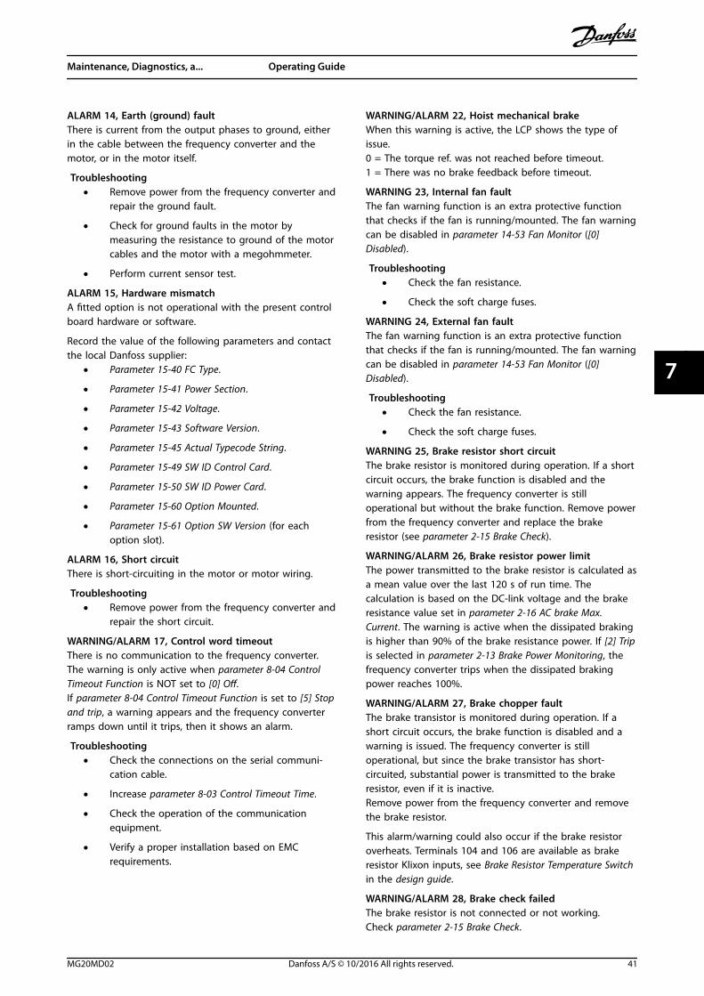
ALARM 14, Earth (ground) faultThere is current from the output phases to ground, eitherin the cable between the frequency converter and themotor, or in the motor itself.
Troubleshooting• Remove power from the frequency converter and
repair the ground fault.
• Check for ground faults in the motor bymeasuring the resistance to ground of the motorcables and the motor with a megohmmeter.
• Perform current sensor test.
ALARM 15, Hardware mismatchA fitted option is not operational with the present controlboard hardware or software.
Record the value of the following parameters and contactthe local Danfoss supplier:
• Parameter 15-40 FC Type.
• Parameter 15-41 Power Section.
• Parameter 15-42 Voltage.
• Parameter 15-43 Software Version.
• Parameter 15-45 Actual Typecode String.
• Parameter 15-49 SW ID Control Card.
• Parameter 15-50 SW ID Power Card.
• Parameter 15-60 Option Mounted.
• Parameter 15-61 Option SW Version (for eachoption slot).
ALARM 16, Short circuitThere is short-circuiting in the motor or motor wiring.
Troubleshooting• Remove power from the frequency converter and
repair the short circuit.
WARNING/ALARM 17, Control word timeoutThere is no communication to the frequency converter.The warning is only active when parameter 8-04 ControlTimeout Function is NOT set to [0] Off.If parameter 8-04 Control Timeout Function is set to [5] Stopand trip, a warning appears and the frequency converterramps down until it trips, then it shows an alarm.
Troubleshooting• Check the connections on the serial communi-
cation cable.
• Increase parameter 8-03 Control Timeout Time.
• Check the operation of the communicationequipment.
• Verify a proper installation based on EMCrequirements.
WARNING/ALARM 22, Hoist mechanical brakeWhen this warning is active, the LCP shows the type ofissue.0 = The torque ref. was not reached before timeout.1 = There was no brake feedback before timeout.
WARNING 23, Internal fan faultThe fan warning function is an extra protective functionthat checks if the fan is running/mounted. The fan warningcan be disabled in parameter 14-53 Fan Monitor ([0]Disabled).
Troubleshooting• Check the fan resistance.
• Check the soft charge fuses.
WARNING 24, External fan faultThe fan warning function is an extra protective functionthat checks if the fan is running/mounted. The fan warningcan be disabled in parameter 14-53 Fan Monitor ([0]Disabled).
Troubleshooting• Check the fan resistance.
• Check the soft charge fuses.
WARNING 25, Brake resistor short circuitThe brake resistor is monitored during operation. If a shortcircuit occurs, the brake function is disabled and thewarning appears. The frequency converter is stilloperational but without the brake function. Remove powerfrom the frequency converter and replace the brakeresistor (see parameter 2-15 Brake Check).
WARNING/ALARM 26, Brake resistor power limitThe power transmitted to the brake resistor is calculated asa mean value over the last 120 s of run time. Thecalculation is based on the DC-link voltage and the brakeresistance value set in parameter 2-16 AC brake Max.Current. The warning is active when the dissipated brakingis higher than 90% of the brake resistance power. If [2] Tripis selected in parameter 2-13 Brake Power Monitoring, thefrequency converter trips when the dissipated brakingpower reaches 100%.
WARNING/ALARM 27, Brake chopper faultThe brake transistor is monitored during operation. If ashort circuit occurs, the brake function is disabled and awarning is issued. The frequency converter is stilloperational, but since the brake transistor has short-circuited, substantial power is transmitted to the brakeresistor, even if it is inactive.Remove power from the frequency converter and removethe brake resistor.
This alarm/warning could also occur if the brake resistoroverheats. Terminals 104 and 106 are available as brakeresistor Klixon inputs, see Brake Resistor Temperature Switchin the design guide.
WARNING/ALARM 28, Brake check failedThe brake resistor is not connected or not working.Check parameter 2-15 Brake Check.
Maintenance, Diagnostics, a... Operating Guide
MG20MD02 Danfoss A/S © 10/2016 All rights reserved. 41
7 7

ALARM 29, Heat Sink tempThe maximum temperature of the heat sink has beenexceeded. The temperature fault does not reset until thetemperature drops below a defined heatsink temperature.The trip and reset points vary based on the frequencyconverter power size.
TroubleshootingCheck for the following conditions:
• Ambient temperature too high.
• Motor cable too long.
• Incorrect airflow clearance above and below thefrequency converter.
• Blocked airflow around the frequency converter.
• Damaged heat sink fan.
• Dirty heat sink.
This alarm is based on the temperature measured by theheat sink sensor mounted inside the IGBT modules.
Troubleshooting• Check the fan resistance.
• Check the soft charge fuses.
• Check the IGBT thermal sensor.
ALARM 30, Motor phase U missingMotor phase U between the frequency converter and themotor is missing.
Troubleshooting• Remove power from the frequency converter and
check motor phase U.
ALARM 31, Motor phase V missingMotor phase V between the frequency converter and themotor is missing.
Troubleshooting• Remove power from the frequency converter and
check motor phase V.
ALARM 32, Motor phase W missingMotor phase W between the frequency converter and themotor is missing.
Troubleshooting• Remove power from the frequency converter and
check motor phase W.
ALARM 33, Inrush faultToo many power-ups have occurred within a short timeperiod. Let the unit cool to operating temperature.
WARNING/ALARM 34, Fieldbus communication faultThe fieldbus on the communication option card is notworking.
WARNING/ALARM 36, Mains failureThis warning/alarm is only active if the supply voltage tothe frequency converter is lost and parameter 14-10 MainsFailure is NOT set to [0] No Function.
Troubleshooting• Check the fuses to the frequency converter and
mains power supply to the unit.
ALARM 38, Internal faultWhen an internal fault occurs, a code number defined inTable 7.4 is shown.
Troubleshooting• Cycle power.
• Check that the option is properly installed.
• Check for loose or missing wiring.
Contact the Danfoss supplier or Danfoss service ifnecessary. Note the code number for further trouble-shooting directions.
Number Text
0 The serial port cannot be initialized. Contact theDanfoss supplier or Danfoss Service.
256–258 Power EEPROM data is defective or too old.
512 The control board EEPROM data is defective or tooold.
513 Communication timeout reading EEPROM data.
514 Communication timeout reading EEPROM data.
515 Application-oriented control cannot recognize theEEPROM data.
516 Cannot write to the EEPROM because a writecommand is in progress.
517 Write command is under timeout.
518 Failure in the EEPROM.
519 Missing or invalid barcode data in EEPROM.
783 Parameter value outside of minimum/maximumlimits.
1024–1279 Sending a CAN telegram failed.
1281 Digital signal processor flash timeout.
1282 Power micro software version mismatch.
1283 Power EEPROM data version mismatch.
1284 Cannot read digital signal processor softwareversion.
1299 The option SW in slot A is too old.
1300 The option SW in slot B is too old.
1301 The option SW in slot C0 is too old.
1302 The option SW in slot C1 is too old.
1315 The option SW in slot A is not supported (notallowed).
1316 The option SW in slot B is not supported (notallowed).
1317 The option SW in slot C0 is not supported (notallowed).
1318 The option SW in slot C1 is not supported (notallowed).
1379 The option A did not respond when calculatingthe platform version.
1380 The option B did not respond when calculatingthe platform version.
Maintenance, Diagnostics, a... VLT® AQUA Drive FC 202
42 Danfoss A/S © 10/2016 All rights reserved. MG20MD02
77

Number Text
1381 The option C0 did not respond when calculatingthe platform version.
1382 The option C1 did not respond when calculatingthe platform version.
1536 An exception in the application-oriented control isregistered. Debug information written in LCP.
1792 The DSP watchdog is active. Debugging of powerpart data, motor-oriented control data nottransferred correctly.
2049 Power data restarted.
2064–2072 H081x: Option in slot x restarted.
2080–2088 H082x: Option in slot x issued a power-up wait.
2096–2104 H983x: Option in slot x issued a legal power-upwait.
2304 Could not read any data from power EEPROM.
2305 Missing SW version from power unit.
2314 Missing power unit data from power unit.
2315 Missing SW version from power unit.
2316 Missing lo_statepage from power unit.
2324 The power card configuration is determined to beincorrect at power-up.
2325 A power card has stopped communicating whilemain power is applied.
2326 The power card configuration is determined to beincorrect after the delay for power cards toregister.
2327 Too many power card locations are registered aspresent.
2330 Power size information between the power cardsdoes not match.
2561 No communication from DSP to ATACD.
2562 No communication from ATACD to DSP (staterunning).
2816 Stack overflow control board module.
2817 Scheduler slow tasks.
2818 Fast tasks.
2819 Parameter thread.
2820 LCP stack overflow.
2821 Serial port overflow.
2822 USB port overflow.
2836 cfListMempool too small.
3072–5122 Parameter value is outside its limits.
5123 Option in slot A: Hardware incompatible withcontrol board hardware.
5124 Option in slot B: Hardware incompatible withcontrol board hardware.
5125 Option in slot C0: Hardware incompatible withcontrol board hardware.
5126 Option in slot C1: Hardware incompatible withcontrol board hardware.
5376–6231 Out of memory.
Table 7.4 Code Numbers for Internal Faults
ALARM 39, Heat sink sensorNo feedback from the heat sink temperature sensor.
The signal from the IGBT thermal sensor is not available onthe power card. The problem could be in the power card,in the gatedrive card, or the ribbon cable between thepower card and the gatedrive card.
WARNING 40, Overload of digital output terminal 27Check the load connected to terminal 27 or remove theshort circuit connection. Check parameter 5-00 Digital I/OMode and parameter 5-01 Terminal 27 Mode.
WARNING 41, Overload of digital output terminal 29Check the load connected to terminal 29 or remove theshort circuit connection. Check parameter 5-00 Digital I/OMode and parameter 5-02 Terminal 29 Mode.
WARNING 42, Overload of digital output on X30/6 oroverload of digital output on X30/7For X30/6, check the load connected to X30/6 or removethe short circuit connection. Check parameter 5-32 TermX30/6 Digi Out (MCB 101).
For X30/7, check the load connected to X30/7 or removethe short circuit connection. Check parameter 5-33 TermX30/7 Digi Out (MCB 101).
ALARM 46, Power card supplyThe supply on the power card is out of range.
There are 3 supplies powered by the switch mode powersupply (SMPS) on the power card: 24 V, 5 V, ±18 V. Whenpowered with 24 V DC with the VLT® 24V DC Supply MCB107 option, only the 24 V and 5 V supplies are monitored.When powered with 3-phase mains voltage, all 3 suppliesare monitored.
WARNING 47, 24 V supply lowThe 24 V DC supply is measured on the control card. Theexternal 24 V DC back-up supply may be overloaded,otherwise contact the Danfoss supplier.
WARNING 48, 1.8 V supply lowThe 1.8 V DC supply used on the control card is outside ofthe allowable limits. The supply is measured on the controlcard. Check for a defective control card. If an option card ispresent, check for an overvoltage condition.
WARNING 49, Speed limitWhen the speed is not within the specified range inparameter 4-11 Motor Speed Low Limit [RPM] andparameter 4-13 Motor Speed High Limit [RPM], the frequencyconverter shows a warning. When the speed is below thespecified limit in parameter 1-86 Trip Speed Low [RPM](except when starting or stopping) the frequency convertertrips.
ALARM 50, AMA calibration failedContact the Danfoss supplier or Danfoss Service.
ALARM 51, AMA check Unom and Inom
The settings for motor voltage, motor current, and motorpower are wrong. Check the settings in parameters 1-20 to1-25.
Maintenance, Diagnostics, a... Operating Guide
MG20MD02 Danfoss A/S © 10/2016 All rights reserved. 43
7 7

ALARM 52, AMA low Inom
The motor current is too low. Check the settings.
ALARM 53, AMA motor too bigThe motor is too big for the AMA to operate.
ALARM 54, AMA motor too smallThe motor is too small for the AMA to operate.
ALARM 55, AMA parameter out of rangeThe parameter values of the motor are outside of theacceptable range. AMA does not run.
ALARM 56, AMA interrupted by userThe user has interrupted the AMA.
ALARM 57, AMA internal faultTry to restart AMA several times, until the AMA is carriedout. Repeated runs may heat the motor to a level wherethe resistance Rs and Rr are increased. Usually this is notcritical.
ALARM 58, AMA Internal faultContact the Danfoss supplier.
WARNING 59, Current limitThe current is higher than the value inparameter 4-18 Current Limit. Ensure that motor data inparameters 1-20 to 1-25 are set correctly. Possibly increasethe current limit. Be sure that the system can operatesafely at a higher limit.
WARNING 60, External interlockExternal interlock has been activated. To resume normaloperation:
1. Apply 24 V DC to the terminal programmed forexternal interlock.
2. Reset the frequency converter via
2a Serial communication.
2b Digital I/O.
2c The [Reset] key.
WARNING 62, Output frequency at maximum limitThe output frequency is higher than the value set inparameter 4-19 Max Output Frequency.
WARNING 64, Voltage LimitThe load and speed combination demands a motorvoltage higher than the actual DC-link voltage.
WARNING/ALARM 65, Control card over temperatureThe control card has reached its trip temperature of 75 °C(167 °F).
WARNING 66, Heat sink temperature lowThe frequency converter is too cold to operate. Thiswarning is based on the temperature sensor in the IGBTmodule. Also, a trickle amount of current can be suppliedto the frequency converter whenever the motor is stoppedby setting parameter 2-00 DC Hold/Preheat Current at 5%and parameter 1-80 Function at Stop.
Troubleshooting• Check the temperature sensor.
• Check the sensor wire between the IGBT and thegatedrive card.
ALARM 67, Option module configuration has changedOne or more options have either been added or removedsince the last power-down. Check that the configurationchange is intentional and reset the unit.
ALARM 68, Safe Stop activatedSTO is activated.
Troubleshooting• To resume normal operation, apply 24 V DC to
terminal 37, then send a reset signal (via bus,digital I/O, or by pressing [Reset]).
ALARM 69, Power card temperatureThe temperature sensor on the power card is either toohot or too cold.
Troubleshooting• Check the operation of the door fans.
• Check that the filters for the door fans are notblocked.
• Check that the gland plate is properly installedon IP21/IP54 (NEMA 1/12) frequency converters.
ALARM 70, Illegal FC configurationThe control card and power card are incompatible.
Troubleshooting• Contact the supplier with the type code of the
unit from the nameplate and the part numbers ofthe cards to check compatibility.
ALARM 71, PTC 1 safe stopSafe Torque Off is activated from the VLT® PTC ThermistorCard MCB 112 (motor too warm). Normal operation can beresumed when the MCB 112 applies 24 V DC to T37 again(when the motor temperature reaches an acceptable level)and when the digital input from the MCB 112 isdeactivated. When that happens, a reset signal must be isbe sent (via bus, digital I/O, or by pressing [Reset]).
NOTICEIf automatic restart is enabled, the motor may startwhen the fault is cleared.
ALARM 72, Dangerous failureSafe Torque Off (STO) with trip lock. Unexpected signallevels on Safe Torque Off (STO) and digital input from theVLT® PTC Thermistor Card MCB 112.
WARNING 73, Safe Stop auto restartSafe Torque Off (STO). With automatic restart enabled, themotor can start when the fault is cleared.
Maintenance, Diagnostics, a... VLT® AQUA Drive FC 202
44 Danfoss A/S © 10/2016 All rights reserved. MG20MD02
77

WARNING 76, Power unit setupThe required number of power units does not match thedetected number of active power units. When replacing anenclosure size F module, this warning occurs if the power-specific data in the module power card does not matchthe rest of the frequency converter. If the power cardconnection is lost, the unit also triggers this warning.
Troubleshooting• Confirm that the spare part and its power card
are the correct part number.
• Ensure that the 44-pin cables between the MDCICand power cards are mounted properly.
WARNING 77, Reduced power modeThis warning indicates that the frequency converter isoperating in reduced power mode (that is, less than theallowed number of inverter sections). This warning isgenerated on power cycle when the frequency converter isset to run with fewer inverters and remains on.
ALARM 79, Illegal power section configurationThe scaling card is the incorrect part number or notinstalled. Also, the MK102 connector on the power cardcould not be installed.
ALARM 80, Drive initialised to default valueParameter settings are initialized to default settings after amanual reset.
Troubleshooting• Reset the unit to clear the alarm.
ALARM 81, CSIV corruptCSIV (Customer-specific initialization values) file has syntaxerrors.
ALARM 82, CSIV parameter errorCSIV (Customer-specific initialization values) failed toinitialize a parameter.
ALARM 85, Dang fail PBPROFIBUS/PROFIsafe error.
ALARM 92, No flowA no-flow condition is detected in the system.Parameter 22-23 No-Flow Function is set for alarm.
Troubleshooting• Troubleshoot the system and reset the frequency
converter after clearing the fault.
ALARM 93, Dry pumpA no-flow condition in the system with the frequencyconverter operating at high speed can indicate a drypump. Parameter 22-26 Dry Pump Function is set for alarm.
Troubleshooting• Troubleshoot the system and reset the frequency
converter after clearing the fault.
ALARM 94, End of curveThe feedback is lower than the setpoint. This condition canindicate leakage in the system. Parameter 22-50 End ofCurve Function is set for alarm.
Troubleshooting• Troubleshoot the system and reset the frequency
converter after clearing the fault.
ALARM 95, Broken beltTorque is below the torque level set for no load, indicatinga broken belt. Parameter 22-60 Broken Belt Function is setfor alarm.
Troubleshooting• Troubleshoot the system and reset the frequency
converter after clearing the fault.
ALARM 100, Derag limit faultThe Deragging feature failed during execution. Check thepump impeller for blockage.
WARNING/ALARM 104, Mixing fan faultThe fan monitor checks that the fan is spinning atfrequency converter power-up or whenever the mixing fanis turned on. If the fan is not operating, the fault is issued.The mixing-fan fault can be configured as a warning or analarm trip by parameter 14-53 Fan Monitor.
Troubleshooting• Cycle power to the frequency converter to
determine if the warning/alarm returns.
WARNING 250, New spare partA component in the frequency converter has beenreplaced. To resume normal operation, reset the frequencyconverter.
WARNING 251, New typecodeThe power card or other components have been replacedand the type code changed.
Troubleshooting• Reset to remove the warning and resume normal
operation.
Maintenance, Diagnostics, a... Operating Guide
MG20MD02 Danfoss A/S © 10/2016 All rights reserved. 45
7 7

7.5 Troubleshooting
Symptom Possible cause Test Solution
Displaydark/Nofunction
Missing input power. See Table 4.3. Check the input power source.
Missing or open fuses, or circuitbreaker tripped.
See Open fuses and tripped circuit breaker inthis table for possible causes.
Follow the recommendations provided.
No power to the LCP. Check the LCP cable for proper connectionor damage.
Replace the faulty LCP or connection cable.
Shortcut on control voltage(terminal 12 or 50) or at controlterminals.
Check the 24 V control voltage supply forterminals 12/13 to 20-39 or 10 V supply forterminals 50–55.
Wire the terminals properly.
Incompatible LCP (LCP from
VLT® 2800 or 5000/6000/8000/FCD or FCM).
–
Use only LCP 101 (P/N 130B1124) or LCP102 (P/N 130B1107).
Wrong contrast setting.–
Press [Status] + []/[] to adjust the
contrast.
Display (LCP) is defective. Test using a different LCP. Replace the faulty LCP or connection cable.
Internal voltage supply fault orSMPS is defective.
–Contact supplier.
Intermittentdisplay
Overloaded supply (SMPS) dueto improper control wiring or afault within the frequencyconverter.
To rule out a problem in the control wiring,disconnect all control wiring by removingthe terminal blocks.
If the display stays lit, the problem is inthe control wiring. Check the wiring forshort circuits or incorrect connections. Ifthe display continues to cut out, follow theprocedure for display dark.
Motor notrunning
Service switch is open ormissing motor connection.
Check if the motor is connected and theconnection is not interrupted (by a serviceswitch or other device).
Connect the motor and check the serviceswitch.
No mains power with 24 V DCoption card.
If the display is functioning but no output,check that mains power is applied to thefrequency converter.
Apply mains power to run the unit.
LCP stop. Check if [Off] has been pressed. Press [Auto On] or [Hand On] (dependingon operating mode) to run the motor.
Missing start signal (Standby). Check parameter 5-10 Terminal 18 DigitalInput for correct setting for terminal 18 (usedefault setting).
Apply a valid start signal to start themotor.
Motor coast signal active(Coasting).
Check parameter 5-12 Terminal 27 DigitalInput for correct setting for terminal 27 (usedefault setting).
Apply 24 V on terminal 27 or program thisterminal to No operation.
Wrong reference signal source. Check the following:
• Reference signal: Local, remote, or busreference.
• Preset reference.
• Terminal connection.
• Scaling of terminals.
• Reference signal availability.
Program the correct settings. Checkparameter 3-13 Reference Site. Set presetreference active in parameter group 3-1*References.
Motor runningin wrongdirection
Motor rotation limit. Check that parameter 4-10 Motor SpeedDirection is programmed correctly.
Program the correct settings.
Active reversing signal. Check if a reversing command isprogrammed for the terminal in parametergroup 5-1* Digital inputs.
Deactivate reversing signal.
Wrong motor phaseconnection.
–See chapter 5.5 Checking Motor Rotation.
Maintenance, Diagnostics, a... VLT® AQUA Drive FC 202
46 Danfoss A/S © 10/2016 All rights reserved. MG20MD02
77

Symptom Possible cause Test Solution
Motor is notreachingmaximumspeed
Frequency limits are setincorrectly.
Check the output limits inparameter 4-13 Motor Speed High Limit[RPM], parameter 4-14 Motor Speed HighLimit [Hz] and parameter 4-19 Max OutputFrequency.
Program the correct limits.
Reference input signal is notscaled correctly.
Check the reference input signal scaling inparameter group 6-0* Analog I/O Mode andparameter group 3-1* References. Check thereference limits in parameter group 3-0*Reference Limit.
Program the correct settings.
Motor speedunstable
Possible incorrect parametersettings.
Check the settings of all motor parameters,including all motor compensation settings.For closed-loop operation, check the PIDsettings.
Check the settings in parameter group 1-6*Load Depen. Setting. For closed-loopoperation, check the settings in parametergroup 20-0* Feedback.
Motor runsrough
Possible overmagnetization. Check for incorrect motor settings in allmotor parameters.
Check the motor settings in parametergroups 1-2* Motor Data, 1-3* Adv MotorData, and 1-5* Load Indep. Setting.
Motor doesnot brake
Possible incorrect settings inthe brake parameters. Possibletoo short ramp-down times.
Check the brake parameters. Check theramp time settings.
Check parameter groups 2-0* DC Brake and3-0* Reference Limits.
Open powerfuses or circuitbreaker trip
Phase-to-phase short circuit. The motor or panel has a short phase-to-phase. Check the motor and panel phasefor short circuits.
Eliminate any short circuits detected.
Motor overload. Motor is overloaded for the application. Perform a start-up test and verify that themotor current is within the specifications. Ifthe motor current exceeds the nameplatefull load current, the motor may run onlywith reduced load. Review the specifi-cations for the application.
Loose connections. Perform a pre-startup check for looseconnections.
Tighten any loose connections.
Mains currentimbalance>3%
Problem with the mains power(See alarm 4, Mains phase lossdescription).
Rotate input power leads into thefrequency converter 1 position: A to B, B toC, C to A.
If imbalanced leg follows the wire, it is apower problem. Check the mains supply.
Problem with the frequencyconverter.
Rotate input power leads into thefrequency converter 1 position: A to B, B toC, C to A.
If imbalance leg stays on the same inputterminal, it is a problem with the unit.Contact the supplier.
Motor currentimbalance>3%
Problem with the motor ormotor wiring.
Rotate output motor cables 1 position: U toV, V to W, W to U.
If imbalanced leg follows the wire, theproblem is in the motor or motor wiring.Check the motor and motor wiring.
Problem with the frequencyconverter.
Rotate output motor cables 1 position: U toV, V to W, W to U.
If imbalance leg stays on same outputterminal, it is a problem with thefrequency converter. Contact the Danfosssupplier.
Frequencyconverteraccelerationproblems
Motor data was enteredincorrectly.
If warnings or alarms occur, see chapter 7.4 List of Warnings and Alarms.Check that motor data is entered correctly.
Increase the ramp-up time inparameter 3-41 Ramp 1 Ramp Up Time.Increase the current limit inparameter 4-18 Current Limit. Increase thetorque limit in parameter 4-16 Torque LimitMotor Mode.
Frequencyconverterdecelerationproblems
Motor data was enteredincorrectly.
If warnings or alarms occur, see chapter 7.4 List of Warnings and Alarms.Check that motor data is entered correctly.
Increase the ramp-down time inparameter 3-42 Ramp 1 Ramp Down Time.Enable overvoltage control inparameter 2-17 Over-voltage Control.
Maintenance, Diagnostics, a... Operating Guide
MG20MD02 Danfoss A/S © 10/2016 All rights reserved. 47
7 7

Symptom Possible cause Test Solution
Acoustic noiseor vibration
Resonances. Bypass critical frequencies by usingparameters in parameter group 4-6* SpeedBypass.
Check if noise and/or vibration have beenreduced to an acceptable limit.
Turn off overmodulation inparameter 14-03 Overmodulation.
Change the switching pattern andfrequency in parameter group 14-0* InverterSwitching.
Increase resonance dampening inparameter 1-64 Resonance Damping.
Table 7.5 Troubleshooting
Maintenance, Diagnostics, a... VLT® AQUA Drive FC 202
48 Danfoss A/S © 10/2016 All rights reserved. MG20MD02
77

8 Specifications
8.1 Electrical Data
8.1.1 Mains Supply 1x200–240 V AC
Type designation P1K1 P1K5 P2K2 P3K0 P3K7 P5K5 P7K5 P15K P22K
Typical shaft output [kW] 1.1 1.5 2.2 3.0 3.7 5.5 7.5 15 22
Typical shaft output at 240 V [hp] 1.5 2.0 2.9 4.0 4.9 7.5 10 20 30
Protection rating IP20/Chassis A3 – – – – – – – –
Protection rating IP21/Type 1 – B1 B1 B1 B1 B1 B2 C1 C2
Protection rating IP55/Type 12 A5 B1 B1 B1 B1 B1 B2 C1 C2
Protection rating IP66/NEMA 4X A5 B1 B1 B1 B1 B1 B2 C1 C2
Output current
Continuous (3x200–240 V) [A] 6.6 7.5 10.6 12.5 16.7 24.2 30.8 59.4 88
Intermittent (3x200–240 V) [A] 7.3 8.3 11.7 13.8 18.4 26.6 33.4 65.3 96.8
Continuous kVA at 208 V [kVA] 2.4 2.7 3.8 4.5 6.0 8.7 11.1 21.4 31.7
Maximum input current
Continuous (1x200–240 V) [A] 12.5 15 20.5 24 32 46 59 111 172
Intermittent (1x200–240 V) [A] 13.8 16.5 22.6 26.4 35.2 50.6 64.9 122.1 189.2
Maximum pre-fuses [A] 20 30 40 40 60 80 100 150 200
Additional specifications
Maximum cable cross-section (mains, motor, brake)
[mm2 (AWG)]0.2–4 (4–10) 10 (7) 35 (2) 50 (1/0) 95 (4/0)
Maximum cable cross-section for mains withdisconnect switch [mm2 (AWG)]
5.26(10)
16 (6) 16 (6) 16 (6) 16 (6) 16 (6) 25 (3) 50 (1/0)2 x 50 (2
x 1/0)9) 10)
Maximum cable cross-section for mains withoutdisconnect switch [mm2 (AWG)]
5.26(10)
16 (6) 16 (6) 16 (6) 16 (6) 16 (6) 25 (3) 50 (1/0) 95 (4/0)
Cable insulation temperature rating [°C (°F)] 75(167)
75(167)
75(167)
75(167)
75(167)
75 (167) 75 (167) 75 (167) 75 (167)
Estimated power loss3) at rated maximum load [W]4) 44 30 44 60 74 110 150 300 440
Efficiency5) 0.98 0.98 0.98 0.98 0.98 0.98 0.98 0.98 0.98
Table 8.1 Mains Supply 1x200–240 V AC, Normal Overload 110% for 1 Minute, P1K1–P22K
Specifications Operating Guide
MG20MD02 Danfoss A/S © 10/2016 All rights reserved. 49
8 8
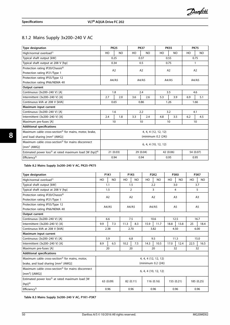
8.1.2 Mains Supply 3x200–240 V AC
Type designation PK25 PK37 PK55 PK75
High/normal overload1) HO NO HO NO HO NO HO NO
Typical shaft output [kW] 0.25 0.37 0.55 0.75
Typical shaft output at 208 V [hp] 0.34 0.5 0.75 1
Protection rating IP20/Chassis6)
Protection rating IP21/Type 1A2 A2 A2 A2
Protection rating IP55/Type 12Protection rating IP66/NEMA 4X
A4/A5 A4/A5 A4/A5 A4/A5
Output current
Continuous (3x200–240 V) [A] 1.8 2.4 3.5 4.6
Intermittent (3x200–240 V) [A] 2.7 2.0 3.6 2.6 5.3 3.9 6.9 5.1
Continuous kVA at 208 V [kVA] 0.65 0.86 1.26 1.66
Maximum input current
Continuous (3x200–240 V) [A] 1.6 2.2 3.2 4.1
Intermittent (3x200–240 V) [A] 2.4 1.8 3.3 2.4 4.8 3.5 6.2 4.5
Maximum pre-fuses [A] 10 10 10 10
Additional specifications
Maximum cable cross-section2) for mains, motor, brake,
and load sharing [mm2 (AWG)]
4, 4, 4 (12, 12, 12)(minimum 0.2 (24))
Maximum cable cross-section2) for mains disconnect
[mm2 (AWG)]6, 4, 4 (10, 12, 12)
Estimated power loss3) at rated maximum load [W (hp)]4) 21 (0.03) 29 (0.04) 42 (0.06) 54 (0.07)
Efficiency5) 0.94 0.94 0.95 0.95
Table 8.2 Mains Supply 3x200–240 V AC, PK25–PK75
Type designation P1K1 P1K5 P2K2 P3K0 P3K7
High/normal overload1) HO NO HO NO HO NO HO NO HO NO
Typical shaft output [kW] 1.1 1.5 2.2 3.0 3.7
Typical shaft output at 208 V [hp] 1.5 2 3 4 5
Protection rating IP20/Chassis6)
Protection rating IP21/Type 1A2 A2 A2 A3 A3
Protection rating IP55/Type 12Protection rating IP66/NEMA 4X
A4/A5 A4/A5 A4/A5 A5 A5
Output current
Continuous (3x200–240 V) [A] 6.6 7.5 10.6 12.5 16.7
Intermittent (3x200–240 V) [A] 9.9 7.3 11.3 8.3 15.9 11.7 18.8 13.8 25 18.4
Continuous kVA at 208 V [kVA] 2.38 2.70 3.82 4.50 6.00
Maximum input current
Continuous (3x200–240 V) [A] 5.9 6.8 9.5 11.3 15.0
Intermittent (3x200–240 V) [A] 8.9 6.5 10.2 7.5 14.3 10.5 17.0 12.4 22.5 16.5
Maximum pre-fuses [A] 20 20 20 32 32
Additional specifications
Maximum cable cross-section2) for mains, motor,
brake, and load sharing [mm2 (AWG)]
4, 4, 4 (12, 12, 12)(minimum 0.2 (24))
Maximum cable cross-section2) for mains disconnect
[mm2] [(AWG)]6, 4, 4 (10, 12, 12)
Estimated power loss3) at rated maximum load [W
(hp)]4)63 (0.09) 82 (0.11) 116 (0.16) 155 (0.21) 185 (0.25)
Efficiency5) 0.96 0.96 0.96 0.96 0.96
Table 8.3 Mains Supply 3x200–240 V AC, P1K1–P3K7
Specifications VLT® AQUA Drive FC 202
50 Danfoss A/S © 10/2016 All rights reserved. MG20MD02
88

Type designation P5K5 P7K5 P11K P15K
High/normal overload1) HO NO HO NO HO NO HO NO
Typical shaft output [kW] 3.7 5.5 5.5 7.5 7.5 11 11 15
Typical shaft output at 208 V [hp] 5.0 7.5 7.5 10 10 15 15 20
IP20/Chassis7) B3 B3 B3 B4
Protection rating IP21/Type 1Protection rating IP55/Type 12Protection rating IP66/NEMA 4X
B1 B1 B1 B2
Output current
Continuous (3x200–240 V) [A] 16.7 24.2 24.2 30.8 30.8 46.2 46.2 59.4
Intermittent (3x200–240 V) [A] 26.7 26.6 38.7 33.9 49.3 50.8 73.9 65.3
Continuous kVA at 208 V [kVA] 6.0 8.7 8.7 11.1 11.1 16.6 16.6 21.4
Maximum input current
Continuous (3x200–240 V) [A] 15.0 22.0 22.0 28.0 28.0 42.0 42.0 54.0
Intermittent (3x200–240 V) [A] 24.0 24.2 35.2 30.8 44.8 46.2 67.2 59.4
Maximum pre-fuses [A] 63 63 63 80
Additional specifications
IP20 maximum cable cross-section2) for mains, brake,
motor, and load sharing [mm2 (AWG)]10, 10, – (8, 8, –) 10, 10, – (8, 8, –) 10, 10, – (8, 8, –) 35, –, – (2, –, –)
Protection rating IP21 maximum cable cross-section2)
for mains, brake, and load sharing [mm2 (AWG)]16, 10, 16 (6, 8, 6) 16, 10, 16 (6, 8, 6) 16, 10, 16 (6, 8, 6) 35, –, – (2, –, –)
Protection rating IP21 maximum cable cross-section2)
for motor
[mm2 (AWG)]
10, 10, – (8, 8, –) 10, 10, – (8, 8, –) 10, 10, – (8, 8, –) 35, 25, 25 (2, 4, 4)
Maximum cable cross-section2) for mains disconnect
[mm2 (AWG)]16, 10, 10 (6, 8, 8) 35 (2)
Estimated power loss3) at rated maximum load [W
(hp)]4)239 (0.33) 310 (0.42)
239(0.33)
310(0.42)
371(0.51)
514 (0.7)463
(0.63)602
(0.82)
Efficiency5) 0.96 0.96 0.96 0.96
Table 8.4 Mains Supply 3x200–240 V AC, P5K5–P15K
Specifications Operating Guide
MG20MD02 Danfoss A/S © 10/2016 All rights reserved. 51
8 8

Type designation P18K P22K P30K P37K P45K
High/normal overload1) HO NO HO NO HO NO HO NO HO NO
Typical shaft output [kW] 15 18.5 18.5 22 22 30 30 37 37 45
Typical shaft output at 208 V [hp] 20 25 25 30 30 40 40 50 50 60
Protection rating IP20/Chassis7) B4 C3 C3 C4 C4
Protection rating IP21/Type 1Protection rating IP55/Type 12Protection rating IP66/NEMA 4X
C1 C1 C1 C2 C2
Output current
Continuous (3x200–240 V) [A] 59.4 74.8 74.8 88.0 88.0 115 115 143 143 170
Intermittent (3x200–240 V) [A] 89.1 82.3 112 96.8 132 127 173 157 215 187
Continuous kVA at 208 V [kVA] 21.4 26.9 26.9 31.7 31.7 41.4 41.4 51.5 51.5 61.2
Maximum input current
Continuous (3x200–240 V) [A] 54.0 68.0 68.0 80.0 80.0 104 104 130 130 154.0
Intermittent (3x200–240 V) [A] 81.0 74.8 102 88.0 120 114 156 143 195 169.0
Maximum pre-fuses [A] 125 125 160 200 250
Additional specifications
Protection rating IP20 maximum cable cross-section for mains, brake, motor, and loadsharing
[mm2 (AWG)]
35 (2) 50 (1) 50 (1) 150 (300 MCM) 150 (300 MCM)
Protection ratings IP21, IP55, IP66 maximumcable cross-section for mains and motor
[mm2 (AWG)]
50 (1) 50 (1) 50 (1) 150 (300 MCM) 150 (300 MCM)
Protection ratings IP21, IP55, IP66 maximumcable cross-section for brake, and load
sharing [mm2 (AWG)]
50 (1) 50 (1) 50 (1) 95 (3/0) 95 (3/0)
Maximum cable cross-section2) for
disconnect [mm2 (AWG)]
50, 35, 35(1, 2, 2)
95, 70, 70(3/0, 2/0, 2/0)
185, 150, 120(350 MCM, 300
MCM, 4/0)
Estimated power loss3) at rated maximum
load [W (hp)]4)
624(0.85)
737 (1) 740 (1)845(1.2)
874(1.2)
1140(1.6)
1143(1.6)
1353(1.8)
1400 (1.9) 1636 (2.2)
Efficiency5) 0.96 0.97 0.97 0.97 0.97
Table 8.5 Mains Supply 3x200–240 V AC, P18K–P45K
8.1.3 Mains Supply 1x380–480 V AC
Type designation P7K5 P11K P18K P37K
Typical shaft output [kW] 7.5 11 18.5 37
Typical shaft output at 240 V [hp] 10 15 25 50
Protection rating IP21/Type 1 B1 B2 C1 C2
Protection rating IP55/Type 12 B1 B2 C1 C2
Protection rating IP66/NEMA 4X B1 B2 C1 C2
Output current
Continuous (3x380–440 V) [A] 16 24 37.5 73
Intermittent (3x380–440 V) [A] 17.6 26.4 41.2 80.3
Continuous (3x441–480 V) [A] 14.5 21 34 65
Intermittent (3x441–480 V) [A] 15.4 23.1 37.4 71.5
Continuous kVA at 400 V [kVA] 11.0 16.6 26 50.6
Continuous kVA at 460 V [kVA] 11.6 16.7 27.1 51.8
Maximum input current
Continuous (1x380–440 V) [A] 33 48 78 151
Intermittent (1x380–440 V) [A] 36 53 85.5 166
Specifications VLT® AQUA Drive FC 202
52 Danfoss A/S © 10/2016 All rights reserved. MG20MD02
88

Type designation P7K5 P11K P18K P37K
Continuous (1x441–480 V) [A] 30 41 72 135
Intermittent (1x441–480 V) [A] 33 46 79.2 148
Maximum pre-fuses [A] 63 80 160 250
Additional specifications
Maximum cable cross-section for mains, motor, and brake
[mm2] (AWG)]10 (7) 35 (2) 50 (1/0) 120 (4/0)
Estimated power loss3) at rated maximum load [W (hp)]4) 300 (0.41) 440 (0.6) 740 (1) 1480 (2)
Efficiency5) 0.96 0.96 0.96 0.96
Table 8.6 Mains Supply 1x380–480 V AC, Normal Overload 110% for 1 Minute, P7K5–P37K
8.1.4 Mains Supply 3x380–480 V AC
Type designation PK37 PK55 PK75 P1K1 P1K5
High/normal overload1) HO NO HO NO HO NO HO NO HO NO
Typical shaft output [kW] 0.37 0.55 0.75 1.1 1.5
Typical shaft output at 460 V [hp] 0.5 0.75 1.0 1.5 2.0
Protection rating IP20/Chassis6) A2 A2 A2 A2 A2
Protection rating IP55/Type 12Protection rating IP66/NEMA 4X
A4/A5 A4/A5 A4/A5 A4/A5 A4/A5
Output current
Continuous (3x380–440 V) [A] 1.3 1.8 2.4 3.0 4.1
Intermittent (3x380–440 V) [A] 2.0 1.4 2.7 2.0 3.6 2.6 4.5 3.3 6.2 4.5
Continuous (3x441–480 V) [A] 1.2 1.6 2.1 2.7 3.4
Intermittent (3x441–480 V) [A] 1.8 1.3 2.4 1.8 3.2 2.3 4.1 3.0 5.1 3.7
Continuous kVA at 400 V [kVA] 0.9 1.3 1.7 2.1 2.8
Continuous kVA at 460 V [kVA] 0.9 1.3 1.7 2.4 2.7
Maximum input current
Continuous (3x380–440 V) [A] 1.2 1.6 2.2 2.7 3.7
Intermittent (3x380–440 V) [A] 1.8 1.3 2.4 1.8 3.3 2.4 4.1 3.0 5.6 4.1
Continuous (3x441–480 V) [A] 1.0 1.4 1.9 2.7 3.1
Intermittent (3x441–480 V) [A] 1.5 1.1 2.1 1.5 2.9 2.1 4.1 3.0 4.7 3.4
Maximum pre-fuses [A] 10 10 10 10 10
Additional specifications
Protection ratings IP20, IP21
maximum cable cross-section2) formains, motor, brake, and load
sharing [mm2 (AWG)]
4, 4, 4 (12, 12, 12)(minimum 0.2 (24))
Protection ratings IP55, IP66
maximum cable cross-section2) formains, motor, brake, and load
sharing [mm2 (AWG)]
4, 4, 4 (12, 12, 12)
Maximum cable cross-section2) for
disconnect [mm2 (AWG)]6, 4, 4 (10, 12, 12)
Estimated power loss3)
at rated maximum load [W (hp)]4)35 (0.05) 42 (0.06) 46 (0.06) 58 (0.08) 62 (0.08)
Efficiency5) 0.93 0.95 0.96 0.96 0.97
Table 8.7 Mains Supply 3x380–480 V AC, PK37–P1K5
Specifications Operating Guide
MG20MD02 Danfoss A/S © 10/2016 All rights reserved. 53
8 8

Type designation P2K2 P3K0 P4K0 P5K5 P7K5
High/normal overload1) HO NO HO NO HO NO HO NO HO NO
Typical shaft output [kW] 2.2 3.0 4.0 5.5 7.5
Typical shaft output at 460 V [hp] 2.9 4.0 5.3 7.5 10
Protection rating IP20/Chassis6) A2 A2 A2 A3 A3
Protection rating IP55/Type 12Protection rating IP66/NEMA 4X
A4/A5 A4/A5 A4/A5 A5 A5
Output current
Continuous (3x380–440 V) [A] 5.6 7.2 10 13 16
Intermittent (3x380–440 V) [A] 8.4 6.2 10.8 7.9 15.0 11.0 19.5 14.3 24.0 17.6
Continuous (3x441–480 V) [A] 4.8 6.3 8.2 11 14.5
Intermittent (3x441–480 V) [A] 7.2 5.3 9.5 6.9 12.3 9.0 16.5 12.1 21.8 16.0
Continuous kVA at 400 V [kVA] 3.9 5.0 6.9 9.0 11.0
Continuous kVA at 460 V [kVA] 3.8 5.0 6.5 8.8 11.6
Maximum input current
Continuous (3x380–440 V) [A] 5.0 6.5 9.0 11.7 14.4
Intermittent (3x380–440 V) [A] 7.5 5.5 9.8 7.2 13.5 9.9 17.6 12.9 21.6 15.8
Continuous(3x441–480 V) [A] 4.3 5.7 7.4 9.9 13.0
Intermittent (3x441–480 V) [A] 6.5 4.7 8.6 6.3 11.1 8.1 14.9 10.9 19.5 14.3
Maximum pre-fuses [A] 20 20 20 30 30
Additional specifications
Protection ratings IP20, IP21
maximum cable cross-section2) formains, motor, brake, and load
sharing [mm2 (AWG)]
4, 4, 4 (12, 12, 12)(minimum 0.2 (24))
Protection ratings IP55, IP66
maximum cable cross-section2) formains, motor, brake, and load
sharing [mm2 (AWG)]
4, 4, 4 (12, 12, 12)
Maximum cable cross-section2) for
disconnect [mm2 (AWG)]6, 4, 4 (10, 12, 12)
Estimated power loss3)
at rated maximum load [W (hp)]4)88 (0.12) 116 (0.16) 124 (0.17) 187 (0.25) 225 (0.31)
Efficiency5) 0.97 0.97 0.97 0.97 0.97
Table 8.8 Mains Supply 3x380–480 V AC, P2K2–P7K5
Specifications VLT® AQUA Drive FC 202
54 Danfoss A/S © 10/2016 All rights reserved. MG20MD02
88

Type designation P11K P15K P18K P22K P30K
High/normal overload1) HO NO HO NO HO NO HO NO HO NO
Typical shaft output [kW] 7.5 11 11 15 15 18.5 22.0 22.0 22.0 30
Typical shaft output at 460 V [hp] 10 15 15 20 20 25 30 30 30 40
Protection rating IP20/Chassis7) B3 B3 B3 B4 B4
Protection rating IP21/Type 1 B1 B1 B1 B2 B2
Protection rating IP55/Type 12Protection rating IP66/NEMA 4X
B1 B1 B1 B2 B2
Output current
Continuous (3x380–440 V) [A] – 24 24 32 32 37.5 37.5 44 44 61
Intermittent (60 s overload)(3x380–440 V) [A]
– 26.4 38.4 35.2 51.2 41.3 60 48.4 70.4 67.1
Continuous (3x441–480 V) [A] – 21 21 27 27 34 34 40 40 52
Intermittent (60 s overload)(3x441–480 V) [A]
– 23.1 33.6 29.7 43.2 37.4 54.4 44 64 61.6
Continuous kVA at 400 V [kVA] – 16.6 16.6 22.2 22.2 26 26 30.5 30.5 42.3
Continuous kVA at 460 V [kVA] – 16.7 16.7 21.5 21.5 27.1 27.1 31.9 31.9 41.4
Maximum input current
Continuous (3x380–440 V) [A] – 22 22 29 29 34 34 40 40 55
Intermittent (60 s overload)(3x380–440 V) [A]
– 24.2 35.2 31.9 46.4 37.4 54.4 44 64 60.5
Continuous (3x441–480 V) [A] – 19 19 25 25 31 31 36 36 47
Intermittent (60 s overload)(3x441–480 V) [A]
– 20.9 30.4 27.5 40 34.1 49.6 39.6 57.6 51.7
Maximum pre-fuses [A] – 63 63 63 63 80
Additional specifications
Protection ratings IP21, IP55, IP66
maximum cable cross-section2) formains, brake, and load sharing
[mm2 (AWG)]
16, 10, 16 (6, 8, 6) 35, –, – (2, –, –)
Protection ratings IP21, IP55, IP66
maximum cable cross-section2) for
motor [mm2 (AWG)]
10, 10,– (8, 8,–) 35, 25, 25 (2, 4, 4)
Protection rating IP20 maximum
cable cross-section2) for mains,brake, motor, and load sharing
[mm2 (AWG)]
10, 10,– (8, 8,–) 35, –, – (2, –, –)
Maximum cable cross-section2) for
disconnect [mm2 (AWG)]16, 10, 10 (6, 8, 8)
Estimated power loss3)
at rated maximum load [W (hp)]4)291 (0.4)
392(0.53)
291 (0.4)392
(0.53)379
(0.52)465
(0.63)444
(0.61)525
(0.72)547
(0.75)739 (1)
Efficiency5) 0.98 0.98 0.98 0.98 0.98
Table 8.9 Mains Supply 3x380–480 V AC, P11K–P30K
Specifications Operating Guide
MG20MD02 Danfoss A/S © 10/2016 All rights reserved. 55
8 8

Type designation P37K P45K P55K P75K P90K
High/normal overload1) HO NO HO NO HO NO HO NO HO NO
Typical shaft output [kW] 30 37 37 45 45 55 55 75 75 90
Typical shaft output at 460 V [hp] 40 50 50 60 60 75 75 100 100 125
Protection rating IP20/Chassis6) B4 C3 C3 C4 C4
Protection rating IP21/Type 1 C1 C1 C1 C2 C2
Protection rating IP55/Type 12Protection rating IP66/NEMA 4X
C1 C1 C1 C2 C2
Output current
Continuous (3x380–440 V) [A] 61 73 73 90 90 106 106 147 147 177
Intermittent (60 s overload) (3x380–440 V) [A]
91.5 80.3 110 99 135 117 159 162 221 195
Continuous (3x441–480 V) [A] 52 65 65 80 80 105 105 130 130 160
Intermittent (60 s overload) (3x441–480 V) [A]
78 71.5 97.5 88 120 116 158 143 195 176
Continuous kVA at 400 V [kVA] 42.3 50.6 50.6 62.4 62.4 73.4 73.4 102 102 123
Continuous kVA at 460 V [kVA] 41.4 51.8 51.8 63.7 63.7 83.7 83.7 104 103.6 128
Maximum input current
Continuous (3x380–440 V) [A] 55 66 66 82 82 96 96 133 133 161
Intermittent (60 s overload) (3x380–440 V) [A]
82.5 72.6 99 90.2 123 106 144 146 200 177
Continuous (3x441–480 V) [A] 47 59 59 73 73 95 95 118 118 145
Intermittent (60 s overload) (3x441–480 V) [A]
70.5 64.9 88.5 80.3 110 105 143 130 177 160
Maximum pre-fuses [A] 100 125 160 250 250
Additional specifications
Protection rating IP20 maximumcable cross-section for mains and
motor [mm2 (AWG)]
35 (2) 50 (1) 50 (1) 150 (300 MCM) 150 (300 MCM)
Protection rating IP20 maximumcable cross-section for brake andload sharing
[mm2 (AWG)]
35 (2) 50 (1) 50 (1) 95 (4/0) 95 (4/0)
Protection ratings IP21, IP55, IP66maximum cable cross-section formains and motor
[mm2 (AWG)]
50 (1) 50 (1) 50 (1) 150 (300 MCM) 150 (300 MCM)
Protection ratings IP21, IP55, IP66maximum cable cross-section for
brake and load sharing [mm2
(AWG)]
50 (1) 50 (1) 50 (1) 95 (3/0) 95 (3/0)
Maximum cable cross-section2) formains disconnect
[mm2 (AWG)]
50, 35, 35(1, 2, 2)
95, 70, 70(3/0, 2/0, 2/0)
185, 150, 120(350 MCM, 300
MCM, 4/0)
Estimated power loss3)
at rated maximum load [W (hp)]4)
570(0.78)
698(0.95)
697(0.95)
843 (1.1) 891 (1.2)1083(1.5)
1022(1.4)
1384(1.9)
1232(1.7)
1474 (2)
Efficiency5) 0.98 0.98 0.98 0.98 0.99
Table 8.10 Mains Supply 3x380–480 V AC, P37K–P90K
Specifications VLT® AQUA Drive FC 202
56 Danfoss A/S © 10/2016 All rights reserved. MG20MD02
88

8.1.5 Mains Supply 3x525–600 V AC
Type designation PK75 P1K1 P1K5 P2K2
High/normal overload1) HO NO HO NO HO NO HO NO
Typical shaft output [kW] 0.75 1.1 1.5 2.2
Typical shaft output [hp] 1 1.5 2 3
Protection rating IP20/ChassisProtection rating IP21/Type 1
A3 A3 A3 A3
Protection rating IP55/Type 12 A5 A5 A5 A5
Output current
Continuous (3x525–550 V) [A] 1.8 2.6 2.9 4.1
Intermittent (3x525–550 V) [A] 2.7 2.0 3.9 2.9 4.4 3.2 6.2 4.5
Continuous (3x551–600 V) [A] 1.7 2.4 2.7 3.9
Intermittent (3x551–600 V) [A] 2.6 1.9 3.6 2.6 4.1 3.0 5.9 4.3
Continuous kVA at 550 V [kVA] 1.7 2.5 2.8 3.9
Continuous kVA at 550 V [kVA] 1.7 2.4 2.7 3.9
Maximum input current
Continuous (3x525–600 V) [A] 1.7 2.4 2.7 4.1
Intermittent (3x525–600 V) [A] 2.6 1.9 3.6 2.6 4.1 3.0 6.2 4.5
Maximum pre-fuses [A] 10 10 10 20
Additional specifications
Maximum cable cross-section2) formains, motor, brake, and load sharing
[mm2 (AWG)]
4,4,4 (12,12,12)(minimum 0.2 (24))
Maximum cable cross-section2) for
mains disconnect [mm2 (AWG)]6,4,4 (10,12,12)
Estimated power loss3)
at rated maximum load [W (hp)]4)35 (0.05) 50 (0.07) 65 (0.09) 92 (0.13)
Efficiency5) 0.97 0.97 0.97 0.97
Table 8.11 Mains Supply 3x525–600 V AC, PK75–P2K2
Specifications Operating Guide
MG20MD02 Danfoss A/S © 10/2016 All rights reserved. 57
8 8
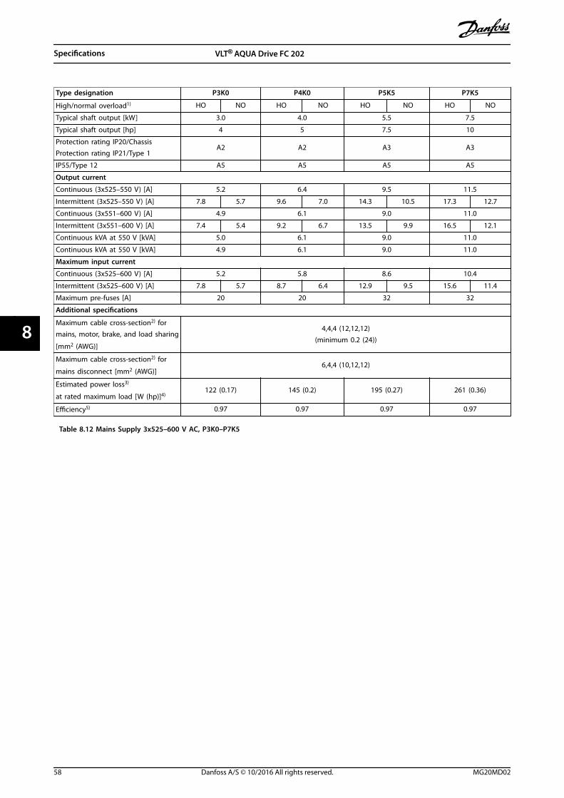
Type designation P3K0 P4K0 P5K5 P7K5
High/normal overload1) HO NO HO NO HO NO HO NO
Typical shaft output [kW] 3.0 4.0 5.5 7.5
Typical shaft output [hp] 4 5 7.5 10
Protection rating IP20/ChassisProtection rating IP21/Type 1
A2 A2 A3 A3
IP55/Type 12 A5 A5 A5 A5
Output current
Continuous (3x525–550 V) [A] 5.2 6.4 9.5 11.5
Intermittent (3x525–550 V) [A] 7.8 5.7 9.6 7.0 14.3 10.5 17.3 12.7
Continuous (3x551–600 V) [A] 4.9 6.1 9.0 11.0
Intermittent (3x551–600 V) [A] 7.4 5.4 9.2 6.7 13.5 9.9 16.5 12.1
Continuous kVA at 550 V [kVA] 5.0 6.1 9.0 11.0
Continuous kVA at 550 V [kVA] 4.9 6.1 9.0 11.0
Maximum input current
Continuous (3x525–600 V) [A] 5.2 5.8 8.6 10.4
Intermittent (3x525–600 V) [A] 7.8 5.7 8.7 6.4 12.9 9.5 15.6 11.4
Maximum pre-fuses [A] 20 20 32 32
Additional specifications
Maximum cable cross-section2) formains, motor, brake, and load sharing
[mm2 (AWG)]
4,4,4 (12,12,12)(minimum 0.2 (24))
Maximum cable cross-section2) for
mains disconnect [mm2 (AWG)]6,4,4 (10,12,12)
Estimated power loss3)
at rated maximum load [W (hp)]4)122 (0.17) 145 (0.2) 195 (0.27) 261 (0.36)
Efficiency5) 0.97 0.97 0.97 0.97
Table 8.12 Mains Supply 3x525–600 V AC, P3K0–P7K5
Specifications VLT® AQUA Drive FC 202
58 Danfoss A/S © 10/2016 All rights reserved. MG20MD02
88

Type designation P11K P15K P18K P22K P30K P37K
High/normal overload1) HO NO HO NO HO NO HO NO HO NO HO NO
Typical shaft output [kW] 7.5 11 11 15 15 18.5 18.5 22 22 30 30 37
Typical shaft output [hp] 10 15 15 20 20 25 25 30 30 40 40 50
Protection rating IP20/Chassis
B3 B3 B3 B4 B4 B4
Protection rating IP21/Type 1Protection rating IP55/Type 12Protection rating IP66/NEMA 4X
B1 B1 B1 B2 B2 C1
Output current
Continuous (3x525–550 V)[A]
11.5 19 19 23 23 28 28 36 36 43 43 54
Intermittent (3x525–550 V) [A]
18.4 21 30 25 37 31 45 40 58 47 65 59
Continuous (3x551–600 V)[A]
11 18 18 22 22 27 27 34 34 41 41 52
Intermittent (3x551–600 V) [A]
17.6 20 29 24 35 30 43 37 54 45 62 57
Continuous kVA at 550 V[kVA]
11 18.1 18.1 21.9 21.9 26.7 26.7 34.3 34.3 41.0 41.0 51.4
Continuous kVA at 575 V[kVA]
11 17.9 17.9 21.9 21.9 26.9 26.9 33.9 33.9 40.8 40.8 51.8
Maximum input current
Continuous at 550 V [A] 10.4 17.2 17.2 20.9 20.9 25.4 25.4 32.7 32.7 39 39 49
Intermittent at 550 V [A] 16.6 19 28 23 33 28 41 36 52 43 59 54
Continuous at 575 V [A] 9.8 16 16 20 20 24 24 31 31 37 37 47
Intermittent at 575 V [A] 15.5 17.6 26 22 32 27 39 34 50 41 56 52
Maximum pre-fuses [A] 40 40 50 60 80 100
Additional specifications
Protection rating IP20,maximum cable cross-
section2) for mains, brake,motor, and load sharing
[mm2 (AWG)]
10, 10,–(8, 8,–)
35,–,–(2,–,–)
Protection ratings IP21,IP55, IP66 maximum cable
cross-section2) for mains,brake, and load sharing
[mm2 (AWG)]
16, 10, 10(6, 8, 8)
35,–,–(2,–,–)
Protection ratings IP21,IP55, IP66 maximum cable
cross-section2) for motor
[mm2 (AWG)]
10, 10,–(8, 8,–)
35, 25, 25(2, 4, 4)
Maximum cable cross-
section2) for mains
disconnect [mm2 (AWG)]
16, 10, 10(6, 8, 8)
50, 35, 35(1, 2, 2)
Estimated power loss3)
at rated maximum load
[W (hp)]4)
220(0.3)
300(0.41)
220(0.3)
300(0.41)
300(0.41)
370(0.5)
370(0.5)
440(0.6)
440(0.6)
600(0.82)
600(0.82)
740 (1)
Efficiency5) 0.98 0.98 0.98 0.98 0.98 0.98
Table 8.13 Mains supply 3x525–600 V AC, P11K–P37K
Specifications Operating Guide
MG20MD02 Danfoss A/S © 10/2016 All rights reserved. 59
8 8

Type designation P45K P55K P75K P90K
High/normal overload1) HO NO HO NO HO NO HO NO
Typical shaft output [kW] 37 45 45 55 55 75 75 90
Typical shaft output [hp] 50 60 60 75 75 100 100 125
Protection rating IP20/Chassis C3 C3 C4 C4
Protection rating IP21/Type 1Protection rating IP55/Type 12Protection rating IP66/NEMA 4X
C1 C1 C2 C2
Output current
Continuous (3x525–550 V) [A] 54 65 65 87 87 105 105 137
Intermittent (3x525–550 V) [A] 81 72 98 96 131 116 158 151
Continuous (3x525–600 V) [A] 52 62 62 83 83 100 100 131
Intermittent (3x525–600 V) [A] 78 68 93 91 125 110 150 144
Continuous kVA at 525 V [kVA] 51.4 61.9 61.9 82.9 82.9 100 100.0 130.5
Continuous kVA at 575 V [kVA] 51.8 61.7 61.7 82.7 82.7 99.6 99.6 130.5
Maximum input current
Continuous at 550 V [A] 49 59 59 78.9 78.9 95.3 95.3 124.3
Intermittent at 550 V [A] 74 65 89 87 118 105 143 137
Continuous at 575 V [A] 47 56 56 75 75 91 91 119
Intermittent at 575 V [A] 70 62 85 83 113 100 137 131
Maximum pre-fuses [A] 150 160 225 250
Additional specifications
Protection rating IP20 maximum cablecross-section for mains and motor
[mm2 (AWG)]
50 (1) 150 (300 MCM)
Protection rating IP20 maximum cablecross-section for brake and load
sharing [mm2 (AWG)]
50 (1) 95 (4/0)
Protection ratings IP21, IP55, IP66maximum cable cross-section formains and motor
[mm2 (AWG)]
50 (1) 150 (300 MCM)
Protection ratings IP21, IP55, IP66maximum cable cross-section for
brake and load sharing [mm2 (AWG)]
50 (1) 95 (4/0)
Maximum cable cross-section2) for
mains disconnect [mm2 (AWG)]
50, 35, 35(1, 2, 2)
95, 70, 70(3/0, 2/0, 2/0)
185, 150, 120(350 MCM, 300 MCM,
4/0)
Estimated power loss3)
at rated maximum load [W (hp)]4)740 (1) 900 (1.2) 900 (1.2) 1100 (1.5) 1100 (1.5) 1500 (2) 1500 (2) 1800 (2.5)
Efficiency5) 0.98 0.98 0.98 0.98
Table 8.14 Mains supply 3x525–600 V AC, P45K–P90K
Specifications VLT® AQUA Drive FC 202
60 Danfoss A/S © 10/2016 All rights reserved. MG20MD02
88

8.1.6 Mains Supply 3x525–690 V AC
Type designation P1K1 P1K5 P2K2 P3K0 P4K0 P5K5 P7K5
High/normal overload1) HO NO HO NO HO NO HO NO HO NO HO NO HO NO
Typical shaft output [kW] 1.1 1.5 2.2 3.0 4.0 5.5 7.5
Typical shaft output [hp] 1.5 2 3 4 5 7.5 10
IP20/Chassis A3 A3 A3 A3 A3 A3 A3
Output current
Continuous (3x525–550 V) [A] 2.1 2.7 3.9 4.9 6.1 9.0 11.0
Intermittent (3x525–550 V) [A] 3.2 2.3 4.1 3.0 5.9 4.3 7.4 5.4 9.2 6.7 13.5 9.9 16.5 12.1
Continuous (3x551–690 V) [A] 1.6 2.2 3.2 4.5 5.5 7.5 10.0
Intermittent (3x551–690 V) [A] 2.4 1.8 3.3 2.4 4.8 3.5 6.8 5.0 8.3 6.1 11.3 8.3 15.0 11.0
Continuous kVA at 525 V [kVA] 1.9 2.5 3.5 4.5 5.5 8.2 10.0
Continuous kVA at 690 V [kVA] 1.9 2.6 3.8 5.4 6.6 9.0 12.0
Maximum input current
Continuous (3x525–550 V) [A] 1.9 2.4 3.5 4.4 5.5 8.1 9.9
Intermittent (3x525–550 V) [A] 2.9 2.1 3.6 2.6 5.3 3.9 6.6 4.8 8.3 6.1 12.2 8.9 14.9 10.9
Continuous (3x551–690 V) [A] 1.4 2.0 2.9 4.0 4.9 6.7 9.0
Intermittent (3x551–690 V) [A] 2.1 1.5 3.0 2.2 4.4 3.2 6.0 4.4 7.4 5.4 10.1 7.4 13.5 9.9
Additional specifications
Maximum cable cross–section2)
for mains, motor, brake, and load
sharing [mm2 (AWG)]
4, 4, 4(12, 12, 12)
(minimum (24)
Maximum cable cross–section2)
for mains disconnect
[mm2 (AWG)]
6, 4, 4(10, 12, 12)
Estimated power loss3)
at rated maximum load [W (hp)]4) 44 (0.06) 60 (0.08) 88 (0.12) 120 (0.16) 160 (0.22) 220 (0.3) 300 (0.41)
Efficiency5) 0.96 0.96 0.96 0.96 0.96 0.96 0.96
Table 8.15 A3 Enclosure, Mains Supply 3x525–690 V AC IP20/Protected Chassis, P1K1–P7K5
Specifications Operating Guide
MG20MD02 Danfoss A/S © 10/2016 All rights reserved. 61
8 8

Type designation P11K P15K P18K P22K P30K
High/normal overload1) HO NO HO NO HO NO HO NO HO NO
Typical shaft output at 550 V [kW] 5.9 7.5 7.5 11 11 15 15 18.5 18.5 22
Typical shaft output at 550 V [hp] 7.5 10 10 15 15 20 20 25 25 30
Typical shaft output at 690 V [kW] 7.5 11 11 15 15 18.5 18.5 22 22 30
Typical shaft output at 690 V [hp] 10 15 15 20 20 25 25 30 30 40
IP20/Chassis B4 B4 B4 B4 B4
IP21/Type 1IP55/Type 12 B2 B2 B2 B2 B2
Output current
Continuous (3x525–550 V) [A] 11 14 14.0 19.0 19.0 23.0 23.0 28.0 28.0 36.0
Intermittent (60 s overload) (3x525–550 V)[A]
17.6 15.4 22.4 20.9 30.4 25.3 36.8 30.8 44.8 39.6
Continuous (3x551–690 V) [A] 10 13 13.0 18.0 18.0 22.0 22.0 27.0 27.0 34.0
Intermittent (60 s overload) (3x551–690 V)[A]
16 14.3 20.8 19.8 28.8 24.2 35.2 29.7 43.2 37.4
Continuous kVA at 550 V [kVA] 10 13.3 13.3 18.1 18.1 21.9 21.9 26.7 26.7 34.3
Continuous kVA at 690 V kVA] 12 15.5 15.5 21.5 21.5 26.3 26.3 32.3 32.3 40.6
Maximum input current
Continuous at 550 V [A] 9.9 15 15.0 19.5 19.5 24.0 24.0 29.0 29.0 36.0
Intermittent (60 s overload) at 550 V [A] 15.8 16.5 23.2 21.5 31.2 26.4 38.4 31.9 46.4 39.6
Continuous (at 690 V) [A] 9 14.5 14.5 19.5 19.5 24.0 24.0 29.0 29.0 36.0
Intermittent (60 s overload) at 690 V [A] 14.4 16 23.2 21.5 31.2 26.4 38.4 31.9 46.4 39.6
Additional specifications
Maximum cable cross–section2 for mains,
motor, brake, and load sharing [mm2 (AWG)]
35, 25, 25(2, 4, 4)
Maximum cable cross–section2) for mains
disconnect [mm2 (AWG)]
16,10,10(6, 8, 8)
Estimated power loss3)
at rated maximum load [W (hp)]4)
150(0.2)
220(0.3)
150(0.2)
220(0.3)
220(0.3)
300(0.41)
300(0.41)
370(0.5)
370(0.5)
440(0.6)
Efficiency5)0.98 0.98 0.98 0.98 0.98
Table 8.16 B2/B4 Enclosure, Mains Supply 3x525–690 V AC IP20/IP21/IP55 – Chassis/NEMA 1/NEMA 12, P11K–P22K
Specifications VLT® AQUA Drive FC 202
62 Danfoss A/S © 10/2016 All rights reserved. MG20MD02
88

Type designation P37K P45K P55K P75K/N75K8) P90K/N90K8)
High/normal overload1) HO NO HO NO HO NO HO NO HO NO
Typical shaft output at 550 V [kW] 22 30 30 37 37 45 45 55 55 75
Typical shaft output at 550 V [hp] 30 40 40 50 50 60 60 75 75 100
Typical shaft output at 690 V [kW] 30 37 37 45 45 55 55 75 75 90
Typical shaft output at 690 V [hp] 40 50 50 60 60 75 75 100 199 125
IP20/Chassis B4 C3 C3 D3h D3h
IP21/Type 1IP55/Type 12 C2 C2 C2 C2 C2
Output current
Continuous (3x525–550 V) [A] 36.0 43.0 43.0 54.0 54.0 65.0 65.0 87.0 87.0 105
Intermittent (60 s overload) (3x525–550 V) [A] 54.0 47.3 64.5 59.4 81.0 71.5 97.5 95.7 130.5 115.5
Continuous (3x551–690 V) [A] 34.0 41.0 41.0 52.0 52.0 62.0 62.0 83.0 83.0 100
Intermittent (60 s overload) (3x551–690 V) [A] 51.0 45.1 61.5 57.2 78.0 68.2 93.0 91.3 124.5 110
Continuous kVA at 550 V [kVA] 34.3 41.0 41.0 51.4 51.4 61.9 61.9 82.9 82.9 100
Continuous kVA at 690 V [kVA] 40.6 49.0 49.0 62.1 62.1 74.1 74.1 99.2 99.2 119.5
Maximum input current
Continuous at 550 V [A] 36.0 49.0 49.0 59.0 59.0 71.0 71.0 87.0 87.0 99.0
Intermittent (60 s overload) at 550 V [A] 54.0 53.9 72.0 64.9 87.0 78.1 105.0 95.7 129 108.9
Continuous at 690 V [A] 36.0 48.0 48.0 58.0 58.0 70.0 70.0 86.0 – –
Intermittent (60 s overload) at 690 V [A] 54.0 52.8 72.0 63.8 87.0 77.0 105 94.6 – –
Additional specifications
Maximum cable cross-section for mains and
motor [mm2 (AWG)]150 (300 MCM)
Maximum cable cross-section for brake and
load sharing [mm2 (AWG)]95 (3/0)
Maximum cable cross-section2) for mains
disconnect [mm2 (AWG)]95 (3/0)
185, 150, 120(350 MCM, 300
MCM, 4/0)–
Estimated power loss3)
at rated maximum load [W (hp)]4)
600(0.82)
740 (1) 740 (1)900(1.2)
900(1.2)
1100(1.5)
1100(1.5)
1500(2)
1500(2)
1800(2.5)
Efficiency5) 0.98 0.98 0.98 0.98 0.98
Table 8.17 B4, C2, C3 Enclosure, Mains Supply 3x525–690 V AC IP20/IP21/IP55 – Chassis/NEMA1/NEMA 12, P30K–P75K
For fuse ratings see chapter 8.8 Fuses and Circuit Breakers.1) High overload=150% or 160% torque for a duration of 60 s. Normal overload=110% torque for a duration of 60 s.2) The 3 values for the maximum cable cross-section are for single core, flexible wire, and flexible wire with sleeve, respectively.3) Applies for dimensioning of frequency converter cooling. If the switching frequency is higher than the default setting, the power losses mayincrease. LCP and typical control card power consumptions are included. For power loss data according to EN 50598–2, refer towww.danfoss.com/vltenergyefficiency.4) Efficiency measured at nominal current. For energy efficiency class see chapter 8.4.1 Ambient Conditions. For part load losses seewww.danfoss.com/vltenergyefficiency.5) Measured using 5 m (16 ft) shielded motor cables at rated load and rated frequency.6) Enclosure sizes A2+A3 can be converted to IP21 using a conversion kit. See also chapters Mechanical mounting and IP21/Type 1 Enclosure kit inthe design guide.7) Enclosure sizes B3+B4 and C3+C4 can be converted to IP21 using a conversion kit. See also chapters Mechanical mounting and IP21/Type 1Enclosure kit in the design guide.8) Enclosure sizes for N75K, N90K are D3h for IP20/Chassis, and D5h for IP54/Type 12.9) Two wires are required.10) Variant not available in IP21.
Specifications Operating Guide
MG20MD02 Danfoss A/S © 10/2016 All rights reserved. 63
8 8
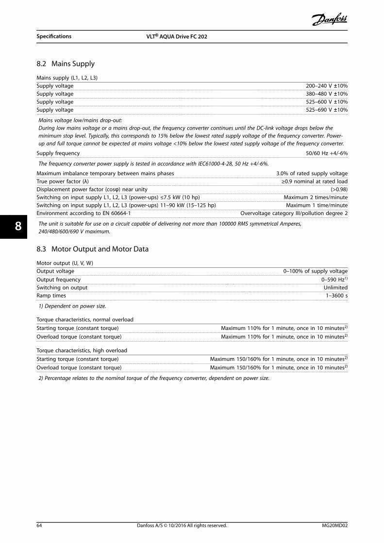
8.2 Mains Supply
Mains supply (L1, L2, L3)Supply voltage 200–240 V ±10%Supply voltage 380–480 V ±10%Supply voltage 525–600 V ±10%Supply voltage 525–690 V ±10%
Mains voltage low/mains drop-out:During low mains voltage or a mains drop-out, the frequency converter continues until the DC-link voltage drops below theminimum stop level. Typically, this corresponds to 15% below the lowest rated supply voltage of the frequency converter. Power-up and full torque cannot be expected at mains voltage <10% below the lowest rated supply voltage of the frequency converter.
Supply frequency 50/60 Hz +4/-6%
The frequency converter power supply is tested in accordance with IEC61000-4-28, 50 Hz +4/-6%.
Maximum imbalance temporary between mains phases 3.0% of rated supply voltageTrue power factor (λ) ≥0.9 nominal at rated loadDisplacement power factor (cosφ) near unity (>0.98)Switching on input supply L1, L2, L3 (power-ups) ≤7.5 kW (10 hp) Maximum 2 times/minuteSwitching on input supply L1, L2, L3 (power-ups) 11–90 kW (15–125 hp) Maximum 1 time/minuteEnvironment according to EN 60664-1 Overvoltage category III/pollution degree 2
The unit is suitable for use on a circuit capable of delivering not more than 100000 RMS symmetrical Amperes,240/480/600/690 V maximum.
8.3 Motor Output and Motor Data
Motor output (U, V, W)Output voltage 0–100% of supply voltageOutput frequency 0–590 Hz1)
Switching on output UnlimitedRamp times 1–3600 s
1) Dependent on power size.
Torque characteristics, normal overloadStarting torque (constant torque) Maximum 110% for 1 minute, once in 10 minutes2)
Overload torque (constant torque) Maximum 110% for 1 minute, once in 10 minutes2)
Torque characteristics, high overloadStarting torque (constant torque) Maximum 150/160% for 1 minute, once in 10 minutes2)
Overload torque (constant torque) Maximum 150/160% for 1 minute, once in 10 minutes2)
2) Percentage relates to the nominal torque of the frequency converter, dependent on power size.
Specifications VLT® AQUA Drive FC 202
64 Danfoss A/S © 10/2016 All rights reserved. MG20MD02
88

8.4 Ambient Conditions
EnvironmentEnclosure size A IP20/Chassis, IP21/Type 1, IP55/Type 12, IP66/Type 4XEnclosure size B1/B2 IP21/Type 1, IP55/Type 12, IP66/Type 4XEnclosure size B3/B4 IP20/ChassisEnclosure size C1/C2 IP21/Type 1, IP55/Type 12, IP66/Type 4XEnclosure size C3/C4 IP20/ChassisEnclosure kit available ≤ enclosure size A IP21/TYPE 1/IP4X topVibration test enclosure A/B/C 1.0 gMaximum relative humidity 5–95% (IEC 721-3-3; Class 3K3 (non-condensing) during operationAggressive environment (IEC 721-3-3), uncoated Class 3C2Aggressive environment (IEC 721-3-3), coated Class 3C3Test method according to IEC 60068-2-43 H2S (10 days)Ambient temperature Maximum 50 °C (122 °F)
Derating for high ambient temperature, see chapter Special Conditions in the design guide.
Minimum ambient temperature during full-scale operation 0 °C (32 °F)Minimum ambient temperature at reduced performance -10 °C (14 °F)Temperature during storage/transport -25 to +65/70 °C (-13 to 149/158 °F)Maximum altitude above sea level without derating 1000 m (3281 ft)Maximum altitude above sea level with derating 3000 m (9843 ft)
Derating for high altitude, see chapter Special Conditions in the design guide.
EMC standards, Emission EN 61800-3EMC standards, Immunity EN 61800-3Energy efficiency class1) IE2
1) Determined according to EN50598-2 at:
• Rated load.
• 90% rated frequency.
• Switching frequency factory setting.
• Switching pattern factory setting.
8.5 Cable Specifications
Maximum motor cable length, shielded/armored 150 m (492 ft)Maximum motor cable length, unshielded/unarmored 300 m (984 ft)Maximum cross-section to motor, mains, load sharing, and brake1)
Maximum cross-section to control terminals, rigid wire 1.5 mm2 or 2 x 0.75 mm2 (16 AWG)Maximum cross-section to control terminals, flexible cable 1 mm2 (18 AWG)Maximum cross-section to control terminals, cable with enclosed core 0.5 mm2 (20 AWG)Minimum cross-section to control terminals 0.25 mm2 (24 AWG)
1) See electrical data tables in chapter 8.1 Electrical Data for more information.
It is mandatory to ground the mains connection properly using T95 (PE) of the frequency converter. The ground connectioncable cross-section must be at least 10 mm2 (8 AWG) or 2 rated mains wires terminated separately according to EN 50178.See alsochapter 4.3.1 Grounding . Use unshielded cable.
8.6 Control Input/Output and Control Data
Control card, RS485 serial communicationTerminal number 68 (P,TX+, RX+), 69 (N,TX-, RX-)Terminal number 61 Common for terminals 68 and 69
The RS485 serial communication circuit is functionally separated from other central circuits and galvanically isolated from thesupply voltage (PELV).
Specifications Operating Guide
MG20MD02 Danfoss A/S © 10/2016 All rights reserved. 65
8 8
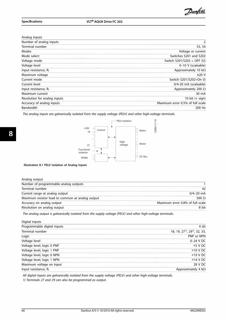
Analog inputsNumber of analog inputs 2Terminal number 53, 54Modes Voltage or currentMode select Switches S201 and S202Voltage mode Switch S201/S202 = OFF (U)Voltage level 0–10 V (scaleable)Input resistance, Ri Approximately 10 kΩMaximum voltage ±20 VCurrent mode Switch S201/S202=On (I)Current level 0/4-20 mA (scaleable)Input resistance, Ri Approximately 200 ΩMaximum current 30 mAResolution for analog inputs 10 bit (+ sign)Accuracy of analog inputs Maximum error 0.5% of full scaleBandwidth 200 Hz
The analog inputs are galvanically isolated from the supply voltage (PELV) and other high-voltage terminals.
Mains
Functionalisolation
PELV isolation
Motor
DC-Bus
Highvoltage
Control+24V
RS485
18
37
130B
A11
7.10
Illustration 8.1 PELV Isolation of Analog Inputs
Analog outputNumber of programmable analog outputs 1Terminal number 42Current range at analog output 0/4–20 mAMaximum resistor load to common at analog output 500 ΩAccuracy on analog output Maximum error 0.8% of full scaleResolution on analog output 8 bit
The analog output is galvanically isolated from the supply voltage (PELV) and other high-voltage terminals.
Digital inputsProgrammable digital inputs 4 (6)Terminal number 18, 19, 271), 291), 32, 33,Logic PNP or NPNVoltage level 0–24 V DCVoltage level, logic 0 PNP <5 V DCVoltage level, logic 1 PNP >10 V DCVoltage level, logic 0 NPN >19 V DCVoltage level, logic 1 NPN <14 V DCMaximum voltage on input 28 V DCInput resistance, Ri Approximately 4 kΩ
All digital inputs are galvanically isolated from the supply voltage (PELV) and other high-voltage terminals.1) Terminals 27 and 29 can also be programmed as output.
Specifications VLT® AQUA Drive FC 202
66 Danfoss A/S © 10/2016 All rights reserved. MG20MD02
88

Digital outputProgrammable digital/pulse outputs 2Terminal number 27, 291)
Voltage level at digital/frequency output 0–24 VMaximum output current (sink or source) 40 mAMaximum load at frequency output 1 kΩMaximum capacitive load at frequency output 10 nFMinimum output frequency at frequency output 0 HzMaximum output frequency at frequency output 32 kHzAccuracy of frequency output Maximum error 0.1% of full scaleResolution of frequency outputs 12 bit
1) Terminal 27 and 29 can also be programmed as input.The digital output is galvanically isolated from the supply voltage (PELV) and other high-voltage terminals.
Pulse inputsProgrammable pulse inputs 2Terminal number pulse 29, 33Maximum frequency at terminal 29, 33 110 kHz (push-pull driven)Maximum frequency at terminal 29, 33 5 kHz (open collector)Minimum frequency at terminal 29, 33 4 HzVoltage level See Digital inputsMaximum voltage on input 28 V DCInput resistance, Ri Approximately 4 kΩPulse input accuracy (0.1–1 kHz) Maximum error 0.1% of full scale
Control card, 24 V DC outputTerminal number 12, 13Maximum load 200 mA
The 24 V DC supply is galvanically isolated from the supply voltage (PELV), but has the same potential as the analog and digitalinputs and outputs.
Relay outputsProgrammable relay outputs 2Relay 01 terminal number 1-3 (break), 1-2 (make)Maximum terminal load (AC-1)1) on 1-3 (NC), 1-2 (NO) (resistive load) 240 V AC, 2 AMaximum terminal load (AC-15)1) (inductive load @ cosφ 0.4) 240 V AC, 0.2 AMaximum terminal load (DC-1)1) on 1-2 (NO), 1-3 (NC) (resistive load) 60 V DC, 1 AMaximum terminal load (DC-13)1) (inductive load) 24 V DC, 0.1 ARelay 02 terminal number 4-6 (break), 4-5 (make)Maximum terminal load (AC-1)1) on 4-5 (NO) (resistive load)2) 3) 400 V AC, 2 AMaximum terminal load (AC-15)1) on 4-5 (NO) (inductive load @ cosφ 0.4) 240 V AC, 0.2 AMaximum terminal load (DC-1)1) on 4-5 (NO) (resistive load) 80 V DC, 2 AMaximum terminal load (DC-13)1) on 4-5 (NO) (inductive load) 24 V DC, 0.1 AMaximum terminal load (AC-1)1) on 4-6 (NC) (resistive load) 240 V AC, 2 AMaximum terminal load (AC-15)1) on 4-6 (NC) (inductive load @ cosφ 0.4) 240 V AC, 0.2 AMaximum terminal load (DC-1)1) on 4-6 (NC) (resistive load) 50 V DC, 2 AMaximum terminal load (DC-13)1) on 4-6 (NC) (inductive load) 24 V DC, 0.1 AMinimum terminal load on 1-3 (NC), 1-2 (NO), 4-6 (NC), 4-5 (NO) 24 V DC, 10 mA, 24 V AC, 20 mAEnvironment according to EN 60664-1 Overvoltage category III/pollution degree 2
1) IEC 60947 parts 4 and 5.The relay contacts are galvanically isolated from the rest of the circuit by reinforced isolation (PELV).2) Overvoltage category II.3) UL applications 300 V AC 2 A.
Specifications Operating Guide
MG20MD02 Danfoss A/S © 10/2016 All rights reserved. 67
8 8

Control card, 10 V DC outputTerminal number 50Output voltage 10.5 V ±0.5 VMaximum load 25 mA
The 10 V DC supply is galvanically isolated from the supply voltage (PELV) and other high-voltage terminals.
Control characteristicsResolution of output frequency at 0–590 Hz ±0.003 HzSystem response time (terminals 18, 19, 27, 29, 32, 33) ≤2 msSpeed control range (open loop) 1:100 of synchronous speedSpeed accuracy (open loop) 30–4000 RPM: Maximum error of ±8 RPM
All control characteristics are based on a 4-pole asynchronous motor.
Control card performanceScan interval 5 ms
Control card, USB serial communicationUSB standard 1.1 (full speed)USB plug USB type B “device” plug
NOTICEConnection to a PC is carried out via a standard host/device USB cable.The USB connection is galvanically isolated from the supply voltage (PELV) and other high-voltage terminals.The USB connection is not galvanically isolated from protective earth. Use only an isolated laptop/PC as a connection tothe USB connector on the frequency converter, or an isolated USB cable/converter.
8.7 Connection Tightening Torques
Torque [N•m (in-lb)]
Enclosure Mains MotorDC
connectionBrake Ground Ground
A2 1.8 (16) 1.8 (16) 1.8 (16) 1.8 (16) 3 (27) 0.6 (5)
A3 1.8 (16) 1.8 (16) 1.8 (16) 1.8 (16) 3 (27) 0.6 (5)
A4 1.8 (16) 1.8 (16) 1.8 (16) 1.8 (16) 3 (27) 0.6 (5)
A5 1.8 (16) 1.8 (16) 1.8 (16) 1.8 (16) 3 (27) 0.6 (5)
B1 1.8 (16) 1.8 (16) 1.5 (13) 1.5 (13.3) 3 (27) 0.6 (5)
B2 4.5 (40) 4.5 (40) 3.7 (33) 3.7 (33) 3 (27) 0.6 (5)
B3 1.8 (16) 1.8 (16) 1.8 (16) 1.8 (16) 3 (27) 0.6 (5)
B4 4.5 (40) 4.5 (40) 4.5 (40) 4.5 (40) 3 (27) 0.6 (5)
C1 10 (89) 10 (89) 10 (89) 10 (89) 3 (27) 0.6 (5)
C2 14/24 (124/221)1) 14/24 (124/221)1) 14 (124) 14 (124) 3 (27) 0.6 (5)
C3 10 (89) 10 (89) 10 (89) 10 (89) 3 (27) 0.6 (5)
C4 14/24 (124/221)1) 14/24 (124/221)1) 14 (124) 14 (124) 3 (27) 0.6 (5)
Table 8.18 Terminal Tightening Torques
1) For different cable dimensions x/y, where x≤95 mm2 (3 AWG) and y≥95 mm2 (3 AWG).
Specifications VLT® AQUA Drive FC 202
68 Danfoss A/S © 10/2016 All rights reserved. MG20MD02
88
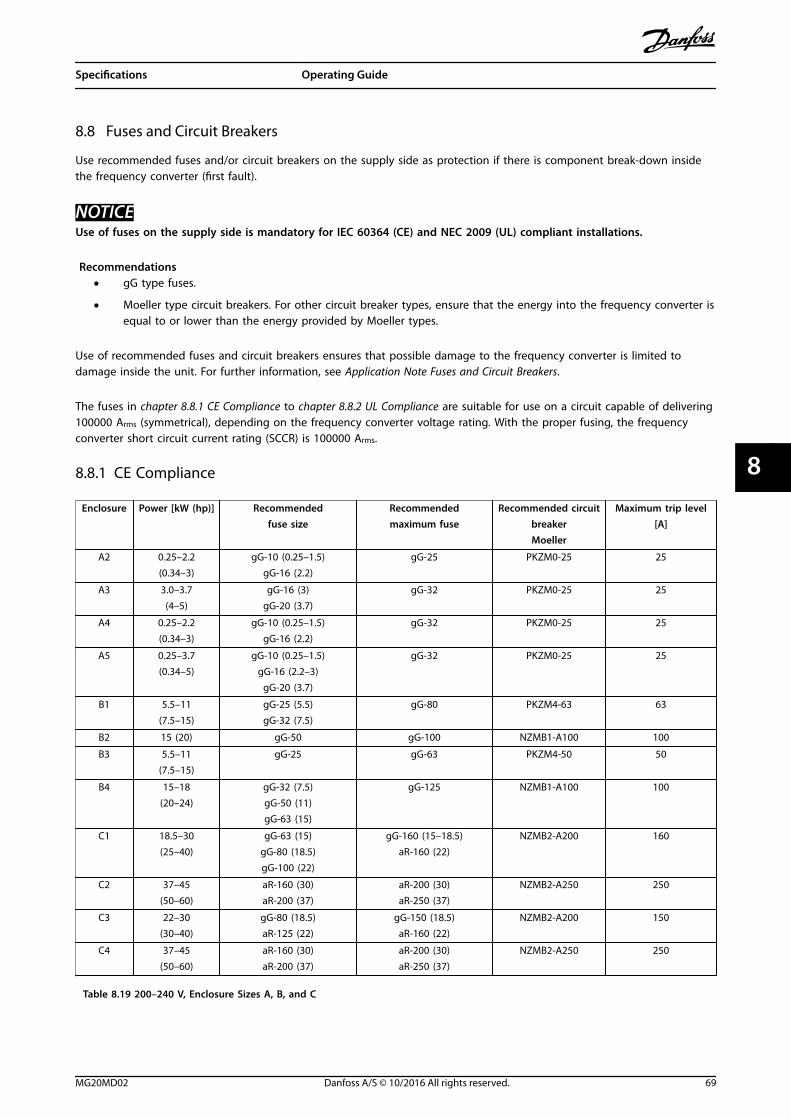
8.8 Fuses and Circuit Breakers
Use recommended fuses and/or circuit breakers on the supply side as protection if there is component break-down insidethe frequency converter (first fault).
NOTICEUse of fuses on the supply side is mandatory for IEC 60364 (CE) and NEC 2009 (UL) compliant installations.
Recommendations• gG type fuses.
• Moeller type circuit breakers. For other circuit breaker types, ensure that the energy into the frequency converter isequal to or lower than the energy provided by Moeller types.
Use of recommended fuses and circuit breakers ensures that possible damage to the frequency converter is limited todamage inside the unit. For further information, see Application Note Fuses and Circuit Breakers.
The fuses in chapter 8.8.1 CE Compliance to chapter 8.8.2 UL Compliance are suitable for use on a circuit capable of delivering100000 Arms (symmetrical), depending on the frequency converter voltage rating. With the proper fusing, the frequencyconverter short circuit current rating (SCCR) is 100000 Arms.
8.8.1 CE Compliance
Enclosure Power [kW (hp)] Recommendedfuse size
Recommendedmaximum fuse
Recommended circuitbreakerMoeller
Maximum trip level[A]
A2 0.25–2.2(0.34–3)
gG-10 (0.25–1.5)gG-16 (2.2)
gG-25 PKZM0-25 25
A3 3.0–3.7(4–5)
gG-16 (3)gG-20 (3.7)
gG-32 PKZM0-25 25
A4 0.25–2.2(0.34–3)
gG-10 (0.25–1.5)gG-16 (2.2)
gG-32 PKZM0-25 25
A5 0.25–3.7(0.34–5)
gG-10 (0.25–1.5)gG-16 (2.2–3)
gG-20 (3.7)
gG-32 PKZM0-25 25
B1 5.5–11(7.5–15)
gG-25 (5.5)gG-32 (7.5)
gG-80 PKZM4-63 63
B2 15 (20) gG-50 gG-100 NZMB1-A100 100
B3 5.5–11(7.5–15)
gG-25 gG-63 PKZM4-50 50
B4 15–18(20–24)
gG-32 (7.5)gG-50 (11)gG-63 (15)
gG-125 NZMB1-A100 100
C1 18.5–30(25–40)
gG-63 (15)gG-80 (18.5)gG-100 (22)
gG-160 (15–18.5)aR-160 (22)
NZMB2-A200 160
C2 37–45(50–60)
aR-160 (30)aR-200 (37)
aR-200 (30)aR-250 (37)
NZMB2-A250 250
C3 22–30(30–40)
gG-80 (18.5)aR-125 (22)
gG-150 (18.5)aR-160 (22)
NZMB2-A200 150
C4 37–45(50–60)
aR-160 (30)aR-200 (37)
aR-200 (30)aR-250 (37)
NZMB2-A250 250
Table 8.19 200–240 V, Enclosure Sizes A, B, and C
Specifications Operating Guide
MG20MD02 Danfoss A/S © 10/2016 All rights reserved. 69
8 8

Enclosure Power [kW (hp)] Recommendedfuse size
Recommendedmaximum fuse
Recommended circuitbreakerMoeller
Maximum trip level[A]
A2 1.1–4.0(1.5–5)
gG-10 (0.37-3)gG-16 (4)
gG-25 PKZM0-25 25
A3 5.5–7.5(7.5–10)
gG-16 gG-32 PKZM0-25 25
A4 1.1–4.0(1.5–5)
gG-10 (0.37-3)gG-16 (4)
gG-32 PKZM0-25 25
A5 1.1–7.5(1.5–10)
gG-10 (0.37-3)gG-16 (4-7.5)
gG-32 PKZM0-25 25
B1 11–18.5(15–25)
gG-40 gG-80 PKZM4-63 63
B2 22–30(30–40)
gG-50 (18.5)gG-63 (22)
gG-100 NZMB1-A100 100
B3 11–18(15–24)
gG-40 gG-63 PKZM4-50 50
B4 22–37(30–50)
gG-50 (18.5)gG-63 (22)gG-80 (30)
gG-125 NZMB1-A100 100
C1 37–55(50–75)
gG-80 (30)gG-100 (37)gG-160 (45)
gG-160 NZMB2-A200 160
C2 75–90(100–125)
aR-200 (55)aR-250 (75)
aR-250 NZMB2-A250 250
C3 45–55(60–75)
gG-100 (37)gG-160 (45)
gG-150 (37)gG-160 (45)
NZMB2-A200 150
C4 75–90(100–125)
aR-200 (55)aR-250 (75)
aR-250 NZMB2-A250 250
Table 8.20 380–480 V, Enclosure Sizes A, B, and C
Specifications VLT® AQUA Drive FC 202
70 Danfoss A/S © 10/2016 All rights reserved. MG20MD02
88

Enclosure Power [kW (hp)] Recommendedfuse size
Recommendedmaximum fuse
Recommended circuitbreakerMoeller
Maximum trip level[A]
A2 1.1–4.0(1.5–5)
gG-10 gG-25 PKZM0-25 25
A3 5.5–7.5(7.5–10)
gG-10 (5.5)gG-16 (7.5)
gG-32 PKZM0-25 25
A5 1.1–7.5(1.5–10)
gG-10 (0.75-5.5)gG-16 (7.5)
gG-32 PKZM0-25 25
B1 11–18(15–24)
gG-25 (11)gG-32 (15)
gG-40 (18.5)
gG-80 PKZM4-63 63
B2 22–30(30–40)
gG-50 (22)gG-63 (30)
gG-100 NZMB1-A100 100
B3 11–18.5(15–25)
gG-25 (11)gG-32 (15)
gG-63 PKZM4-50 50
B4 22–37(30–50)
gG-40 (18.5)gG-50 (22)gG-63 (30)
gG-125 NZMB1-A100 100
C1 37–55(50–75)
gG-63 (37)gG-100 (45)aR-160 (55)
gG-160 (37-45)aR-250 (55)
NZMB2-A200 160
C2 75–90(100–125)
aR-200 (75) aR-250 NZMB2-A250 250
C3 45–55(60–75)
gG-63 (37)gG-100 (45)
gG-150 NZMB2-A200 150
C4 75–90(100–125)
aR-160 (55)aR-200 (75)
aR-250 NZMB2-A250 250
Table 8.21 525–600 V, Enclosure Sizes A, B, and C
Enclosure Power [kW (hp)] Recommended fuse size Recommendedmaximum fuse
Recommended circuitbreakerDanfoss
Maximum triplevel [A]
A3
1.1 (1.5) gG-6 gG-25 CTI25M 10-16 16
1.5 (2) gG-6 gG-25 CTI25M 10-16 16
2.2 (3) gG-6 gG-25 CTI25M 10-16 16
3 (4) gG-10 gG-25 CTI25M 10-16 16
4 (5) gG-10 gG-25 CTI25M 10-16 16
5.5 (7.5) gG-16 gG-25 CTI25M 10-16 16
7.5 (10) gG-16 gG-25 CTI25M 10-16 16
B2
11 (15) gG-25 gG-63 – –
15 (20) gG-25 gG-63 – –
18 (24) gG-32 – – –
22 (30) gG-32 – – –
C2
30 (40) gG-40 – – –
37 (50) gG-63 gG-80 – –
45 (60) gG-63 gG-100 – –
55 (75) gG-80 gG-125 – –
75 (100) gG-100 gG-160 – –
C337 (50) gG-100 gG-125 – –
45 (60) gG-125 gG-160 – –
Table 8.22 525–690 V, Enclosure Sizes A, B, and C
Specifications Operating Guide
MG20MD02 Danfoss A/S © 10/2016 All rights reserved. 71
8 8

8.8.2 UL Compliance
Recommended maximum fuse
Power[kW(hp)]
Maxi-mum
prefusesize [A]
Buss-mannJFHR2
Buss-mannRK1
Buss-mann
J
Buss-mann
T
Buss-mann
CC
Buss-mann
CC
Buss-mann
CC
SIBARK1
Littelfuse
RK1
Ferraz-Shawmut
CC
Ferraz-Shawmut
RK1
Ferraz-Shawmut
J
1.1(1.5) 15 FWX-15 KTN-R15 JKS-15 JJN-15
FNQ-R-15
KTK-R-15
LP-CC-15
5017906-016
KLN-R15 ATM-R15 A2K-15R HSJ15
1.5 (2) 20 FWX-20 KTN-R20 JKS-20 JJN-20FNQ-R-20
KTK-R-20
LP-CC-20
5017906-020
KLN-R20 ATM-R20 A2K-20R HSJ20
2.2 (3) 301) FWX-30 KTN-R30 JKS-30 JJN-30FNQ-R-30
KTK-R-30
LP-CC-30
5012406-032
KLN-R30 ATM-R30 A2K-30R HSJ30
3.0 (4) 35 FWX-35 KTN-R35 JKS-35 JJN-35 – – – –KLN-R35 – A2K-35R HSJ35
3.7 (5) 50 FWX-50 KTN-R50 JKS-50 JJN-50 – – –5014006-
050KLN-R50 – A2K-50R HSJ50
5.5(7.5) 602) FWX-60 KTN-R60 JKS-60 JJN-60 – – –
5014006-063
KLN-R60 – A2K-60R HSJ60
7.5(10) 80 FWX-80 KTN-R80 JKS-80 JJN-80 – – –
5014006-080
KLN-R80 – A2K-80R HSJ80
15(20) 150
FWX-150
KTN-R150 JKS-150 JJN-150 – – –
2028220-150
KLN-R150 – A2K-150R HSJ150
22(30) 200
FWX-200
KTN-R200 JKS-200 JJN-200 – – –
2028220-200
KLN-R200 – A2K-200R HSJ200
Table 8.23 1x200–240 V, Enclosure Sizes A, B, and C
1) Siba allowed up to 32 A.2) Siba allowed up to 63 A.
Recommended maximum fuse
Power[kW(hp)]
Maxi-mumpre-fusesize[A]
Buss-mannJFHR2
Buss-mannRK1
Buss-mann
J
Buss-mann
T
Buss-mann
CC
Buss-mann
CC
Buss-mann
CC
SIBARK1
Littelfuse
RK1
Ferraz-Shawmut
CC
Ferraz-Shawmut
RK1
Ferraz-Shawmut
J
7.5(10) 60 FWH-60 KTS-R60 JKS-60 JJS-60 – – –
5014006-063 KLS-R60 – A6K-60R HSJ60
11 (15) 80 FWH-80 KTS-R80 JKS-80 JJS-80 – – –2028220-
100 KLS-R80 – A6K-80R HSJ80
22 (30) 150FWH-150
KTS-R150 JKS-150 JJS-150 – – –
2028220-160 KLS-R150 – A6K-150R HSJ150
37 (50) 200FWH-200
KTS-R200 JKS-200 JJS-200 – – –
2028220-200 KLS-200 – A6K-200R HSJ200
Table 8.24 1x380–500 V, Enclosure Sizes B and C
• KTS-fuses from Bussmann may substitute KTN for 240 V frequency converters.
• FWH-fuses from Bussmann may substitute FWX for 240 V frequency converters.
• JJS-fuses from Bussmann may substitute JJN for 240 V frequency converters.
• KLSR fuses from Littelfuse may substitute KLNR fuses for 240 V frequency converters.
• A6KR fuses from Ferraz-Shawmut may substitute A2KR for 240 V frequency converters.
Specifications VLT® AQUA Drive FC 202
72 Danfoss A/S © 10/2016 All rights reserved. MG20MD02
88
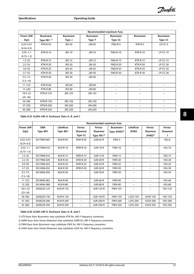
Recommended maximum fuse
Power [kW(hp)]
Bussmann
Type RK1 1)
BussmannType J
BussmannType T
BussmannType CC
Bussmann BussmannType CC
0.25–0.37(0.34–0.5)
KTN-R-05 JKS-05 JJN-05 FNQ-R-5 KTK-R-5 LP-CC-5
0.55–1.1(0.75–1.5)
KTN-R-10 JKS-10 JJN-10 FNQ-R-10 KTK-R-10 LP-CC-10
1.5 (2) KTN-R-15 JKS-15 JJN-15 FNQ-R-15 KTK-R-15 LP-CC-15
2.2 (3) KTN-R-20 JKS-20 JJN-20 FNQ-R-20 KTK-R-20 LP-CC-20
3.0 (4) KTN-R-25 JKS-25 JJN-25 FNQ-R-25 KTK-R-25 LP-CC-25
3.7 (5) KTN-R-30 JKS-30 JJN-30 FNQ-R-30 KTK-R-30 LP-CC-30
5.5–7.5(7.5–10)
KTN-R-50 JKS-50 JJN-50 – – –
11 (15) KTN-R-60 JKS-60 JJN-60 – – –
15 (20) KTN-R-80 JKS-80 JJN-80 – – –
18.5–22(25–30)
KTN-R-125 JKS-125 JJN-125 – – –
30 (40) KTN-R-150 JKS-150 JJN-150 – – –
37 (50) KTN-R-200 JKS-200 JJN-200 – – –
45 (60) KTN-R-250 JKS-250 JJN-250 – – –
Table 8.25 3x200–240 V, Enclosure Sizes A, B, and C
Recommended maximum fuse
Power [kW(hp)]
SIBAType RK1
LittelfuseType RK1
Ferraz-ShawmutType CC
Ferraz-Shawmut
Type RK12)
Bussmann
Type JFHR23)
LittelfuseJFHR2
Ferraz-Shawmut
JFHR24)
Ferraz-Shawmut
J
0.25–0.37(0.34–0.5)
5017906-005 KLN-R-05 ATM-R-05 A2K-05-R FWX-5 – – HSJ-6
0.55–1.1(0.75–1.5)
5017906-010 KLN-R-10 ATM-R-10 A2K-10-R FWX-10 – – HSJ-10
1.5 (2) 5017906-016 KLN-R-15 ATM-R-15 A2K-15-R FWX-15 – – HSJ-15
2.2 (3) 5017906-020 KLN-R-20 ATM-R-20 A2K-20-R FWX-20 – – HSJ-20
3.0 (4) 5017906-025 KLN-R-25 ATM-R-25 A2K-25-R FWX-25 – – HSJ-25
3.7 (5) 5012406-032 KLN-R-30 ATM-R-30 A2K-30-R FWX-30 – – HSJ-30
5.5–7.5(7.5–10)
5014006-050 KLN-R-50 – A2K-50-R FWX-50 – – HSJ-50
11 (15) 5014006-063 KLN-R-60 – A2K-60-R FWX-60 – – HSJ-60
15 (20) 5014006-080 KLN-R-80 – A2K-80-R FWX-80 – – HSJ-80
18.5–22(25–30)
2028220-125 KLN-R-125 – A2K-125-R FWX-125 – – HSJ-125
30 (40) 2028220-150 KLN-R-150 – A2K-150-R FWX-150 L25S-150 A25X-150 HSJ-150
37 (50) 2028220-200 KLN-R-200 – A2K-200-R FWX-200 L25S-200 A25X-200 HSJ-200
45 (60) 2028220-250 KLN-R-250 – A2K-250-R FWX-250 L25S-250 A25X-250 HSJ-250
Table 8.26 3x200–240 V, Enclosure Sizes A, B, and C
1) KTS-fuses from Bussmann may substitute KTN for 240 V frequency converters.2) A6KR fuses from Ferraz-Shawmut may substitute A2KR for 240 V frequency converters.3) FWH-fuses from Bussmann may substitute FWX for 240 V frequency converters.4) A50X fuses from Ferraz-Shawmut may substitute A25X for 240 V frequency converters.
Specifications Operating Guide
MG20MD02 Danfoss A/S © 10/2016 All rights reserved. 73
8 8

Recommended maximum fuse
Power[kW (hp)]
BussmannType RK1
BussmannType J
BussmannType T
BussmannType CC
BussmannType CC
BussmannType CC
– KTS-R-6 JKS-6 JJS-6 FNQ-R-6 KTK-R-6 LP-CC-6
1.1–2.2(1.5–3)
KTS-R-10 JKS-10 JJS-10 FNQ-R-10 KTK-R-10 LP-CC-10
3 (4) KTS-R-15 JKS-15 JJS-15 FNQ-R-15 KTK-R-15 LP-CC-15
4 (5) KTS-R-20 JKS-20 JJS-20 FNQ-R-20 KTK-R-20 LP-CC-20
5.5 (7.5) KTS-R-25 JKS-25 JJS-25 FNQ-R-25 KTK-R-25 LP-CC-25
7.5 (10) KTS-R-30 JKS-30 JJS-30 FNQ-R-30 KTK-R-30 LP-CC-30
11 (15) KTS-R-40 JKS-40 JJS-40 – – –
15 (20) KTS-R-50 JKS-50 JJS-50 – – –
22 (30) KTS-R-60 JKS-60 JJS-60 – – –
30 (40) KTS-R-80 JKS-80 JJS-80 – – –
37 (50) KTS-R-100 JKS-100 JJS-100 – – –
45 (60) KTS-R-125 JKS-125 JJS-125 – – –
55 (75) KTS-R-150 JKS-150 JJS-150 – – –
75 (100) KTS-R-200 JKS-200 JJS-200 – – –
90 (125) KTS-R-250 JKS-250 JJS-250 – – –
Table 8.27 3x380–480 V, Enclosure Sizes A, B, and C
Recommended maximum fuse
Power[kW (hp)]
SIBAType RK1
LittelfuseType RK1
Ferraz-ShawmutType CC
Ferraz-ShawmutType RK1
BussmannJFHR2
Ferraz-Shawmut
J
Ferraz-Shawmut
JFHR21)
LittelfuseJFHR2
– 5017906-006 KLS-R-6 ATM-R-6 A6K-6-R FWH-6 HSJ-6 – –
1.1–2.2(1.5–3)
5017906-010 KLS-R-10 ATM-R-10 A6K-10-R FWH-10 HSJ-10 – –
3 (4) 5017906-016 KLS-R-15 ATM-R-15 A6K-15-R FWH-15 HSJ-15 – –
4 (5) 5017906-020 KLS-R-20 ATM-R-20 A6K-20-R FWH-20 HSJ-20 – –
5.5 (7.5) 5017906-025 KLS-R-25 ATM-R-25 A6K-25-R FWH-25 HSJ-25 – –
7.5 (10) 5012406-032 KLS-R-30 ATM-R-30 A6K-30-R FWH-30 HSJ-30 – –
11 (15) 5014006-040 KLS-R-40 – A6K-40-R FWH-40 HSJ-40 – –
15 (20) 5014006-050 KLS-R-50 – A6K-50-R FWH-50 HSJ-50 – –
22 (30) 5014006-063 KLS-R-60 – A6K-60-R FWH-60 HSJ-60 – –
30 (40) 2028220-100 KLS-R-80 – A6K-80-R FWH-80 HSJ-80 – –
37 (50) 2028220-125 KLS-R-100 – A6K-100-R FWH-100 HSJ-100 – –
45 (60) 2028220-125 KLS-R-125 – A6K-125-R FWH-125 HSJ-125 – –
55 (75) 2028220-160 KLS-R-150 – A6K-150-R FWH-150 HSJ-150 – –
75 (100) 2028220-200 KLS-R-200 – A6K-200-R FWH-200 HSJ-200 A50-P-225 L50-S-225
90 (125) 2028220-250 KLS-R-250 – A6K-250-R FWH-250 HSJ-250 A50-P-250 L50-S-250
Table 8.28 3x380–480 V, Enclosure Sizes A, B, and C
1) Ferraz-Shawmut A50QS fuses may substitute A50P fuses.
Specifications VLT® AQUA Drive FC 202
74 Danfoss A/S © 10/2016 All rights reserved. MG20MD02
88

Recommended maximum fuse
Power[kW(hp)]
BussmannType RK1
Bussmann
Type J
BussmannType T
BussmannType CC
Bussmann
Type CC
Bussmann
Type CC
SIBAType RK1
LittelfuseType RK1
Ferraz-ShawmutType RK1
Ferraz-Shawmut
J
0.75–1.1
(1–1.5)
KTS-R-5 JKS-5 JJS-6 FNQ-R-5 KTK-R-5 LP-CC-5 5017906-005 KLS-R-005 A6K-5-R HSJ-6
1.5–2.2(2–3)
KTS-R-10 JKS-10 JJS-10 FNQ-R-10 KTK-R-10 LP-CC-10 5017906-010 KLS-R-010 A6K-10-R HSJ-10
3 (4) KTS-R15 JKS-15 JJS-15 FNQ-R-15 KTK-R-15 LP-CC-15 5017906-016 KLS-R-015 A6K-15-R HSJ-15
4 (5) KTS-R20 JKS-20 JJS-20 FNQ-R-20 KTK-R-20 LP-CC-20 5017906-020 KLS-R-020 A6K-20-R HSJ-20
5.5(7.5)
KTS-R-25 JKS-25 JJS-25 FNQ-R-25 KTK-R-25 LP-CC-25 5017906-025 KLS-R-025 A6K-25-R HSJ-25
7.5 (10) KTS-R-30 JKS-30 JJS-30 FNQ-R-30 KTK-R-30 LP-CC-30 5017906-030 KLS-R-030 A6K-30-R HSJ-30
11–15(15–20)
KTS-R-35 JKS-35 JJS-35 – – – 5014006-040 KLS-R-035 A6K-35-R HSJ-35
18 (24) KTS-R-45 JKS-45 JJS-45 – – – 5014006-050 KLS-R-045 A6K-45-R HSJ-45
22 (30) KTS-R-50 JKS-50 JJS-50 – – – 5014006-050 KLS-R-050 A6K-50-R HSJ-50
30 (40) KTS-R-60 JKS-60 JJS-60 – – – 5014006-063 KLS-R-060 A6K-60-R HSJ-60
37 (50) KTS-R-80 JKS-80 JJS-80 – – – 5014006-080 KLS-R-075 A6K-80-R HSJ-80
45 (60) KTS-R-100 JKS-100 JJS-100 – – – 5014006-100 KLS-R-100 A6K-100-R HSJ-100
55 (75) KTS-R-125 JKS-125 JJS-125 – – – 2028220-125 KLS-R-125 A6K-125-R HSJ-125
75(100)
KTS-R-150 JKS-150 JJS-150 – – – 2028220-150 KLS-R-150 A6K-150-R HSJ-150
90(125)
KTS-R-175 JKS-175 JJS-175 – – – 2028220-200 KLS-R-175 A6K-175-R HSJ-175
Table 8.29 3x525–600 V, Enclosure Sizes A, B, and C
Recommended maximum fuse
Power[kW(hp)]
Maximumpre-fuse
[A]
BussmannE52273
RK1/JDDZ
BussmannE4273J/JDDZ
BussmannE4273
T/JDDZ
SIBAE180276
RK1/JDDZ
LittelfuseE81895
RK1/JDDZ
Ferraz-Shawmut
E163267/E2137RK1/JDDZ
Ferraz-Shawmut
E2137J/HSJ
11–15(15–20)
30 KTS-R-30 JKS-30 JJS-30 5017906-030 KLS-R-030 A6K-30-R HST-30
22 (30) 45 KTS-R-45 JKS-45 JJS-45 5014006-050 KLS-R-045 A6K-45-R HST-45
30 (40) 60 KTS-R-60 JKS-60 JJS-60 5014006-063 KLS-R-060 A6K-60-R HST-60
37 (50) 80 KTS-R-80 JKS-80 JJS-80 5014006-080 KLS-R-075 A6K-80-R HST-80
45 (60) 90 KTS-R-90 JKS-90 JJS-90 5014006-100 KLS-R-090 A6K-90-R HST-90
55 (75) 100 KTS-R-100 JKS-100 JJS-100 5014006-100 KLS-R-100 A6K-100-R HST-100
75 (100) 125 KTS-R-125 JKS-125 JJS-125 2028220-125 KLS-150 A6K-125-R HST-125
90 (125) 150 KTS-R-150 JKS-150 JJS-150 2028220-150 KLS-175 A6K-150-R HST-150
Table 8.30 3x525–690 V, Enclosure Sizes B and C
Specifications Operating Guide
MG20MD02 Danfoss A/S © 10/2016 All rights reserved. 75
8 8

8.9 Power Ratings, Weight, and Dimensions
Enclosure size [kW (hp)] A2 A3 A4 A5
3x525–690 V T7 – – – –
3x525–600 V T6 –0.75–7.5
(1–10)– 0.75–7.5 (1–10)
3x380–480 V T4 0.37–4.0 (0.5–5)5.5–7.5(7.5–10)
0.37–4.0(0.5–5)
0.37–7.5 (0.5–10)
1x380–480 V S4 – –1.1–4.0(1.5–5)
–
3x200–240 V T2 0.25–3.0 (0.34–4) 3.7 (0.5)0.25–2.2 (0.34–
3)0.25–3.7 (0.34–
5)
1x200–240 V S2 – 1.1 (1.5) 1.1–2.2 (1.5–3) 1.1 (1.5)
IPNEMA
20Chassis
21Type 1
20Chassis
21Type 1
55/66Type 12/4X
55/66Type 12/4X
Height [mm (in)]
Height of backplate A1) 268 (10.6) 375 (14.8) 268 (10.6) 375 (14.8) 390 (15.4) 420 (16.5)
Height with de-coupling plate for fieldbuscables
A 374 (14.7) – 374 (14.7) – – –
Distance between mounting holes a 257 (10.1) 350 (13.8) 257 (10.1) 350 (13.8) 401 (15.8) 402 (15.8)
Width [mm (in)]
Width of backplate B 90 (3.5) 90 (3.5) 130 (5.1) 130 (5.1) 200 (7.9) 242 (9.5)
Width of backplate with 1 C option B 130 (5.1) 130 (5.1) 170 (6.7) 170 (6.7) – 242 (9.5)
Width of backplate with 2 C options B 90 (3.5) 90 (3.5) 130 (5.1) 130 (5.1) – 242 (9.5)
Distance between mounting holes b 70 (2.8) 70 (2.8) 110 (4.3) 110 (4.3) 171 (6.7) 215 (8.5)
Depth2) [mm (in)]
Without option A/B C 205 (8.1) 205 (8.1) 205 (8.1) 205 (8.1) 175 (6.9) 200 (7.9)
With option A/B C 220 (8.7) 220 (8.7) 220 (8.7) 220 (8.7) 175 (6.9) 200 (7.9)
Screw holes [mm (in)]
c 8.0 (0.31) 8.0 (0.31) 8.0 (0.31) 8.0 (0.31) 8.25 (0.32) 8.2 (0.32)
d ø11 (0.43) ø11 (0.43) ø11 (0.43) ø11 (0.43) ø12 (0.47) ø12 (0.47)
e ø5.5 (0.22) ø5.5 (0.22) ø5.5 (0.22) ø5.5 (0.22) ø6.5 (0.26) ø6.5 (0.26)
f 9 (0.35) 9 (0.35) 9 (0.35) 9 (0.35) 6 (0.24) 9 (0.35)
Maximum weight [kg (lb)] 4.9 (10.8) 5.3 (11.7) 6.6 (14.6) 7 (15.4) 9.7 (21.4) 14 (31)
1) See Illustration 3.4 and Illustration 3.5 for top and bottom mounting holes.2) Depth of enclosure varies with different options installed.
Table 8.31 Power Ratings, Weight, and Dimensions, Enclosure Sizes A2-A5
Specifications VLT® AQUA Drive FC 202
76 Danfoss A/S © 10/2016 All rights reserved. MG20MD02
88

Enclosure size [kW (hp)] B1 B2 B3 B4 C1 C2 C3 C4
3x525–690 V T7 –11–30
(15–40)– – –
37–90(50–125)
– –
3x525–600 V T611–18.5(15–25)
22–30(30–40)
11–18.5(15–25)
22–37(30–50)
37–55(50–75)
75–90(100–125)
45–55(60–75)
75–90(100–125)
3x380–480 V T411–18.5(15–25)
22–30(30–40)
11–18.5(15–25)
22–37(30–50)
37–55(50–75)
75–90(100–125)
45–55(60–75)
75–90(100–125)
1x380–480 V S4 7.5 (10) 11 (15) – – 18 (24) 37 (50) – –
3x200–240 V T25.5–11
(7.5–15)15 (20)
5.5–11(7.5–15)
15–18.5(20–25)
18.5–30(25–40)
37–45(50–60)
22–30(30–40)
37–45(50–60)
1x200–240 V S21.5–3.7
(2–5)7.5 (10) – – 15 (20) 22 (30) – –
IPNEMA
21/55/66Type 1/12/4X
21/55/66Type
1/12/4X
20Chassis
20Chassis
21/55/66Type
1/12/4X
21/55/66Type
1/12/4X
20Chassis
20Chassis
Height [mm (in)]
Height of backplate A1) 480 (18.9) 650 (25.6) 399 (15.7) 520 (20.5) 680 (26.8) 770 (30.3)550
(21.7)660 (26)
Height with de-coupling plate forfieldbus cables
A – – 419 (16.5) 595 (23.4) – –630
(24.8)800
(31.5)
Distance between mountingholes
a 454 (17.9) 624 (24.6) 380 (15) 495 (19.5) 648 (25.5) 739 (29.1)521
(20.5)631
(24.8)
Width [mm (in)]
Width of backplate B 242 (9.5) 242 (9.5) 165 (6.5) 231 (9.1) 308 (12.1) 370 (14.6)308
(12.1)370
(14.6)
Width of backplate with 1 Coption
B 242 (9.5) 242 (9.5) 205 (8.1) 231 (9.1) 308 (12.1) 370 (14.6)308
(12.1)370
(14.6)
Width of backplate with 2 Coptions
B 242 (9.5) 242 (9.5) 165 (6.5) 231 (9.1) 308 (12.1) 370 (14.6)308
(12.1)370
(14.6)
Distance between mountingholes
b 210 (8.3) 210 (8.3) 140 (5.5) 200 (7.9) 272 (10.7) 334 (13.1)270
(10.6)330 (13)
Depth2)[mm (in)]
Without option A/B C 260 (10.2) 260 (10.2) 248 (9.8) 242 (9.5) 310 (12.2) 335 (13.2)333
(13.1)333
(13.1)
With option A/B C 260 (10.2) 260 (10.2) 262 (10.3) 242 (9.5) 310 (12.2) 335 (13.2)333
(13.1)333
(13.1)
Screw holes [mm (in)]
c 12 (0.47) 12 (0.47) 8 (0.32) – 12 (0.47) 12 (0.47) – –
d ø19 (0.75) ø19 (0.75) 12 (0.47) – ø19 (0.75) ø19 (0.75) – –
e ø9 (0.35) ø9 (0.35) 6.8 (0.27) 8.5 (0.33) ø9 (0.35) ø9 (0.35) 8.5 (0.33)8.5
(0.33)
f 9 (0.35) 9 (0.35) 7.9 (0.31) 15 (0.59) 9.8 (0.39) 9.8 (0.39) 17 (0.67)17
(0.67)
Maximum weight [kg (lb)] 23 (51) 27 (60) 12 (26.5) 23.5 (52) 45 (99) 65 (143) 35 (77) 50 (110)
1) See Illustration 3.4 and Illustration 3.5 for top and bottom mounting holes.2) Depth of enclosure varies with different options installed.
Table 8.32 Power Ratings, Weight, and Dimensions, Enclosure Sizes B1–B4, C1–C4
Specifications Operating Guide
MG20MD02 Danfoss A/S © 10/2016 All rights reserved. 77
8 8
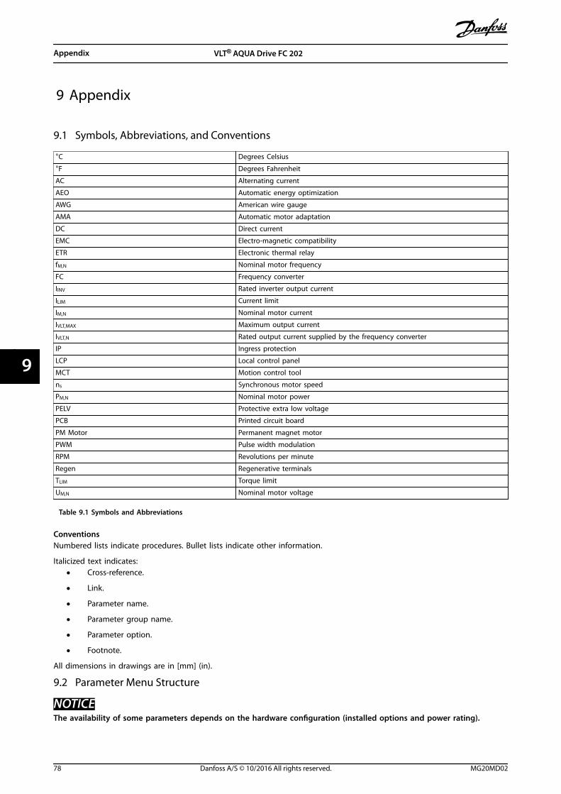
9 Appendix
9.1 Symbols, Abbreviations, and Conventions
°C Degrees Celsius
°F Degrees Fahrenheit
AC Alternating current
AEO Automatic energy optimization
AWG American wire gauge
AMA Automatic motor adaptation
DC Direct current
EMC Electro-magnetic compatibility
ETR Electronic thermal relay
fM,N Nominal motor frequency
FC Frequency converter
IINV Rated inverter output current
ILIM Current limit
IM,N Nominal motor current
IVLT,MAX Maximum output current
IVLT,N Rated output current supplied by the frequency converter
IP Ingress protection
LCP Local control panel
MCT Motion control tool
ns Synchronous motor speed
PM,N Nominal motor power
PELV Protective extra low voltage
PCB Printed circuit board
PM Motor Permanent magnet motor
PWM Pulse width modulation
RPM Revolutions per minute
Regen Regenerative terminals
TLIM Torque limit
UM,N Nominal motor voltage
Table 9.1 Symbols and Abbreviations
ConventionsNumbered lists indicate procedures. Bullet lists indicate other information.
Italicized text indicates:• Cross-reference.
• Link.
• Parameter name.
• Parameter group name.
• Parameter option.
• Footnote.
All dimensions in drawings are in [mm] (in).
9.2 Parameter Menu Structure
NOTICEThe availability of some parameters depends on the hardware configuration (installed options and power rating).
Appendix VLT® AQUA Drive FC 202
78 Danfoss A/S © 10/2016 All rights reserved. MG20MD02
99

0-**
Ope
ratio
n /
Dis
play
0-0*
Basi
c Se
ttin
gs0-
01La
ngua
ge0-
02M
otor
Spe
ed U
nit
0-03
Regi
onal
Set
tings
0-04
Ope
ratin
g S
tate
at
Pow
er-u
p0-
05Lo
cal M
ode
Uni
t0-
1*Se
t-up
Ope
ratio
ns0-
10Ac
tive
Set-
up0-
11Pr
ogra
mm
ing
Set
-up
0-12
This
Set
-up
Lin
ked
to
0-13
Read
out:
Lin
ked
Set
-ups
0-14
Read
out:
Pro
g. S
et-u
ps /
Cha
nnel
0-2*
LCP
Dis
play
0-20
Dis
play
Lin
e 1.
1 Sm
all
0-21
Dis
play
Lin
e 1.
2 Sm
all
0-22
Dis
play
Lin
e 1.
3 Sm
all
0-23
Dis
play
Lin
e 2
Larg
e0-
24D
ispl
ay L
ine
3 La
rge
0-25
My
Pers
onal
Men
u0-
3*LC
P C
usto
m R
eado
ut0-
30Cu
stom
Rea
dout
Uni
t0-
31Cu
stom
Rea
dout
Min
Val
ue0-
32Cu
stom
Rea
dout
Max
Val
ue0-
37D
ispl
ay T
ext
10-
38D
ispl
ay T
ext
20-
39D
ispl
ay T
ext
30-
4*LC
P K
eypa
d0-
40[H
and
on]
Key
on
LCP
0-41
[Off]
Key
on
LCP
0-42
[Aut
o o
n] K
ey o
n L
CP0-
43[R
eset
] Ke
y on
LCP
0-44
[Off/
Rese
t] K
ey o
n L
CP0-
45[D
rive
Bypa
ss]
Key
on L
CP0-
5*Co
py/S
ave
0-50
LCP
Cop
y0-
51Se
t-up
Cop
y0-
6*Pa
ssw
ord
0-60
Mai
n M
enu
Pas
swor
d0-
61Ac
cess
to
Mai
n M
enu
w/o
Pas
swor
d0-
65Pe
rson
al M
enu
Pas
swor
d0-
66Ac
cess
to
Per
sona
l Men
u w
/o P
assw
ord
0-67
Bus
Pass
wor
d A
cces
s0-
7*Cl
ock
Sett
ings
0-70
Dat
e an
d T
ime
0-71
Dat
e Fo
rmat
0-72
Tim
e Fo
rmat
0-74
DST
/Sum
mer
time
0-76
DST
/Sum
mer
time
Star
t0-
77D
ST/S
umm
ertim
e En
d0-
79Cl
ock
Faul
t0-
81W
orki
ng D
ays
0-82
Addi
tiona
l Wor
king
Day
s0-
83Ad
ditio
nal N
on-W
orki
ng D
ays
0-89
Dat
e an
d T
ime
Read
out
1-**
Load
and
Mot
or1-
0*G
ener
al S
ettin
gs1-
00Co
nfigu
ratio
n M
ode
1-01
Mot
or C
ontr
ol P
rinci
ple
1-03
Torq
ue C
hara
cter
istic
s1-
04O
verlo
ad M
ode
1-06
Cloc
kwis
e D
irect
ion
1-1*
Mot
or S
elec
tion
1-10
Mot
or C
onst
ruct
ion
1-1*
VVC+
PM
/SYN
RM
1-14
Dam
ping
Gai
n1-
15Lo
w S
peed
Filt
er T
ime
Cons
t.1-
16H
igh
Spe
ed F
ilter
Tim
e Co
nst.
1-17
Volta
ge fi
lter
time
cons
t.1-
2*M
otor
Dat
a1-
20M
otor
Pow
er [k
W]
1-21
Mot
or P
ower
[HP]
1-22
Mot
or V
olta
ge1-
23M
otor
Fre
quen
cy1-
24M
otor
Cur
rent
1-25
Mot
or N
omin
al S
peed
1-26
Mot
or C
ont.
Rat
ed T
orqu
e1-
28M
otor
Rot
atio
n C
heck
1-29
Auto
mat
ic M
otor
Ada
ptat
ion
(AM
A)
1-3*
Adv
. Mot
or D
ata
1-30
Stat
or R
esis
tanc
e (R
s)1-
31Ro
tor
Resi
stan
ce (R
r)1-
33St
ator
Lea
kage
Rea
ctan
ce (X
1)1-
34Ro
tor
Leak
age
Reac
tanc
e (X
2)1-
35M
ain
Rea
ctan
ce (X
h)1-
36Iro
n L
oss
Resi
stan
ce (R
fe)
1-37
d-ax
is In
duct
ance
(Ld)
1-38
q-ax
is In
duct
ance
(Lq)
1-39
Mot
or P
oles
1-40
Back
EM
F at
100
0 RP
M1-
44d-
axis
Indu
ctan
ce S
at. (
LdSa
t)1-
45q-
axis
Indu
ctan
ce S
at. (
LqSa
t)1-
46Po
sitio
n D
etec
tion
Gai
n1-
47To
rque
Cal
ibra
tion
1-48
Indu
ctan
ce S
at. P
oint
1-5*
Load
Inde
p. S
ettin
g1-
50M
otor
Mag
netis
atio
n a
t Ze
ro S
peed
1-51
Min
Spe
ed N
orm
al M
agne
tisin
g [R
PM]
1-52
Min
Spe
ed N
orm
al M
agne
tisin
g [H
z]1-
55V/
f Ch
arac
teris
tic -
V1-
56V/
f Ch
arac
teris
tic -
f1-
58Fl
ying
Sta
rt T
est
Puls
es C
urre
nt1-
59Fl
ying
Sta
rt T
est
Puls
es F
requ
ency
1-6*
Load
Dep
en. S
ettin
g1-
60Lo
w S
peed
Loa
d C
ompe
nsat
ion
1-61
Hig
h S
peed
Loa
d C
ompe
nsat
ion
1-62
Slip
Com
pens
atio
n1-
63Sl
ip C
ompe
nsat
ion
Tim
e Co
nsta
nt1-
64Re
sona
nce
Dam
ping
1-65
Reso
nanc
e D
ampi
ng T
ime
Cons
tant
1-66
Min
. Cur
rent
at
Low
Spe
ed1-
7*St
art
Adj
ustm
ents
1-70
PM S
tart
Mod
e1-
71St
art
Del
ay1-
72St
art
Func
tion
1-73
Flyi
ng S
tart
1-77
Com
pres
sor
Star
t M
ax S
peed
[RPM
]1-
78Co
mpr
esso
r St
art
Max
Spe
ed [H
z]
1-79
Pum
p S
tart
Max
Tim
e to
Trip
1-8*
Stop
Adj
ustm
ents
1-80
Func
tion
at
Stop
1-81
Min
Spe
ed fo
r Fu
nctio
n a
t St
op [R
PM]
1-82
Min
Spe
ed fo
r Fu
nctio
n a
t St
op [H
z]1-
86Tr
ip S
peed
Low
[RPM
]1-
87Tr
ip S
peed
Low
[Hz]
1-9*
Mot
or T
empe
ratu
re1-
90M
otor
The
rmal
Pro
tect
ion
1-91
Mot
or E
xter
nal F
an1-
93Th
erm
isto
r So
urce
1-94
ATEX
ETR
cur
.lim
. spe
ed re
duct
ion
1-98
ATEX
ETR
inte
rpol
. poi
nts
freq
.1-
99AT
EX E
TR in
terp
ol p
oint
s cu
rren
t2-
**Br
akes
2-0*
DC-
Brak
e2-
00D
C H
old/
Preh
eat
Curr
ent
2-01
DC
Bra
ke C
urre
nt2-
02D
C B
raki
ng T
ime
2-03
DC
Bra
ke C
ut In
Spe
ed [R
PM]
2-04
DC
Bra
ke C
ut In
Spe
ed [H
z]2-
06Pa
rkin
g C
urre
nt2-
07Pa
rkin
g T
ime
2-1*
Brak
e En
ergy
Fun
ct.
2-10
Brak
e Fu
nctio
n2-
11Br
ake
Resi
stor
(ohm
)2-
12Br
ake
Pow
er L
imit
(kW
)2-
13Br
ake
Pow
er M
onito
ring
2-15
Brak
e Ch
eck
2-16
AC b
rake
Max
. Cur
rent
2-17
Ove
r-vo
ltage
Con
trol
3-**
Refe
renc
e /
Ram
ps3-
0*Re
fere
nce
Lim
its3-
02M
inim
um R
efer
ence
3-03
Max
imum
Ref
eren
ce3-
04Re
fere
nce
Func
tion
3-1*
Refe
renc
es3-
10Pr
eset
Ref
eren
ce3-
11Jo
g S
peed
[Hz]
3-13
Refe
renc
e Si
te3-
14Pr
eset
Rel
ativ
e Re
fere
nce
3-15
Refe
renc
e 1
Sour
ce3-
16Re
fere
nce
2 So
urce
3-17
Refe
renc
e 3
Sour
ce3-
19Jo
g S
peed
[RPM
]3-
4*Ra
mp
13-
41Ra
mp
1 R
amp
Up
Tim
e3-
42Ra
mp
1 R
amp
Dow
n T
ime
3-5*
Ram
p 2
3-51
Ram
p 2
Ram
p U
p T
ime
3-52
Ram
p 2
Ram
p D
own
Tim
e3-
8*O
ther
Ram
ps3-
80Jo
g R
amp
Tim
e3-
81Q
uick
Sto
p R
amp
Tim
e3-
84In
itial
Ram
p T
ime
3-85
Chec
k Va
lve
Ram
p T
ime
3-86
Chec
k Va
lve
Ram
p E
nd S
peed
[RPM
]3-
87Ch
eck
Valv
e Ra
mp
End
Spe
ed [H
Z]3-
88Fi
nal R
amp
Tim
e
3-9*
Dig
ital P
ot.M
eter
3-90
Step
Siz
e3-
91Ra
mp
Tim
e3-
92Po
wer
Res
tore
3-93
Max
imum
Lim
it3-
94M
inim
um L
imit
3-95
Ram
p D
elay
4-**
Lim
its /
War
ning
s4-
1*M
otor
Lim
its4-
10M
otor
Spe
ed D
irect
ion
4-11
Mot
or S
peed
Low
Lim
it [R
PM]
4-12
Mot
or S
peed
Low
Lim
it [H
z]4-
13M
otor
Spe
ed H
igh
Lim
it [R
PM]
4-14
Mot
or S
peed
Hig
h L
imit
[Hz]
4-16
Torq
ue L
imit
Mot
or M
ode
4-17
Torq
ue L
imit
Gen
erat
or M
ode
4-18
Curr
ent
Lim
it4-
19M
ax O
utpu
t Fr
eque
ncy
4-5*
Adj
. War
ning
s4-
50W
arni
ng C
urre
nt L
ow4-
51W
arni
ng C
urre
nt H
igh
4-52
War
ning
Spe
ed L
ow4-
53W
arni
ng S
peed
Hig
h4-
54W
arni
ng R
efer
ence
Low
4-55
War
ning
Ref
eren
ce H
igh
4-56
War
ning
Fee
dbac
k Lo
w4-
57W
arni
ng F
eedb
ack
Hig
h4-
58M
issi
ng M
otor
Pha
se F
unct
ion
4-6*
Spee
d B
ypas
s4-
60By
pass
Spe
ed F
rom
[RPM
]4-
61By
pass
Spe
ed F
rom
[Hz]
4-62
Bypa
ss S
peed
To
[RPM
]4-
63By
pass
Spe
ed T
o [H
z]4-
64Se
mi-A
uto
Byp
ass
Set-
up5-
**D
igita
l In/
Out
5-0*
Dig
ital I
/O m
ode
5-00
Dig
ital I
/O M
ode
5-01
Term
inal
27
Mod
e5-
02Te
rmin
al 2
9 M
ode
5-1*
Dig
ital I
nput
s5-
10Te
rmin
al 1
8 D
igita
l Inp
ut5-
11Te
rmin
al 1
9 D
igita
l Inp
ut5-
12Te
rmin
al 2
7 D
igita
l Inp
ut5-
13Te
rmin
al 2
9 D
igita
l Inp
ut5-
14Te
rmin
al 3
2 D
igita
l Inp
ut5-
15Te
rmin
al 3
3 D
igita
l Inp
ut5-
16Te
rmin
al X
30/2
Dig
ital I
nput
5-17
Term
inal
X30
/3 D
igita
l Inp
ut5-
18Te
rmin
al X
30/4
Dig
ital I
nput
5-19
Term
inal
37
Dig
ital I
nput
5-20
Term
inal
X46
/1 D
igita
l Inp
ut5-
21Te
rmin
al X
46/3
Dig
ital I
nput
5-22
Term
inal
X46
/5 D
igita
l Inp
ut5-
23Te
rmin
al X
46/7
Dig
ital I
nput
5-24
Term
inal
X46
/9 D
igita
l Inp
ut5-
25Te
rmin
al X
46/1
1 D
igita
l Inp
ut5-
26Te
rmin
al X
46/1
3 D
igita
l Inp
ut5-
3*D
igita
l Out
puts
5-30
Term
inal
27
Dig
ital O
utpu
t
5-31
Term
inal
29
Dig
ital O
utpu
t5-
32Te
rm X
30/6
Dig
i Out
(MCB
101
)5-
33Te
rm X
30/7
Dig
i Out
(MCB
101
)5-
4*Re
lays
5-40
Func
tion
Rel
ay5-
41O
n D
elay
, Rel
ay5-
42O
ff D
elay
, Rel
ay5-
5*Pu
lse
Inpu
t5-
50Te
rm. 2
9 Lo
w F
requ
ency
5-51
Term
. 29
Hig
h F
requ
ency
5-52
Term
. 29
Low
Ref
./Fee
db. V
alue
5-53
Term
. 29
Hig
h R
ef./F
eedb
. Val
ue5-
54Pu
lse
Filte
r Ti
me
Cons
tant
#29
5-55
Term
. 33
Low
Fre
quen
cy5-
56Te
rm. 3
3 H
igh
Fre
quen
cy5-
57Te
rm. 3
3 Lo
w R
ef./F
eedb
. Val
ue5-
58Te
rm. 3
3 H
igh
Ref
./Fee
db. V
alue
5-59
Puls
e Fi
lter
Tim
e Co
nsta
nt #
335-
6*Pu
lse
Out
put
5-60
Term
inal
27
Puls
e O
utpu
t Va
riabl
e5-
62Pu
lse
Out
put
Max
Fre
q #
275-
63Te
rmin
al 2
9 Pu
lse
Out
put
Varia
ble
5-65
Puls
e O
utpu
t M
ax F
req
#29
5-66
Term
inal
X30
/6 P
ulse
Out
put
Varia
ble
5-68
Puls
e O
utpu
t M
ax F
req
#X3
0/6
5-8*
I/O O
ptio
ns5-
80A
HF
Cap
Rec
onne
ct D
elay
5-9*
Bus
Cont
rolle
d5-
90D
igita
l & R
elay
Bus
Con
trol
5-93
Puls
e O
ut #
27 B
us C
ontr
ol5-
94Pu
lse
Out
#27
Tim
eout
Pre
set
5-95
Puls
e O
ut #
29 B
us C
ontr
ol5-
96Pu
lse
Out
#29
Tim
eout
Pre
set
5-97
Puls
e O
ut #
X30/
6 Bu
s Co
ntro
l5-
98Pu
lse
Out
#X3
0/6
Tim
eout
Pre
set
6-**
Ana
log
In/O
ut6-
0*A
nalo
g I/
O M
ode
6-00
Live
Zer
o T
imeo
ut T
ime
6-01
Live
Zer
o T
imeo
ut F
unct
ion
6-1*
Ana
log
Inpu
t 53
6-10
Term
inal
53
Low
Vol
tage
6-11
Term
inal
53
Hig
h V
olta
ge6-
12Te
rmin
al 5
3 Lo
w C
urre
nt6-
13Te
rmin
al 5
3 H
igh
Cur
rent
6-14
Term
inal
53
Low
Ref
./Fee
db. V
alue
6-15
Term
inal
53
Hig
h R
ef./F
eedb
. Val
ue6-
16Te
rmin
al 5
3 Fi
lter
Tim
e Co
nsta
nt6-
17Te
rmin
al 5
3 Li
ve Z
ero
6-2*
Ana
log
Inpu
t 54
6-20
Term
inal
54
Low
Vol
tage
6-21
Term
inal
54
Hig
h V
olta
ge6-
22Te
rmin
al 5
4 Lo
w C
urre
nt6-
23Te
rmin
al 5
4 H
igh
Cur
rent
6-24
Term
inal
54
Low
Ref
./Fee
db. V
alue
6-25
Term
inal
54
Hig
h R
ef./F
eedb
. Val
ue6-
26Te
rmin
al 5
4 Fi
lter
Tim
e Co
nsta
nt6-
27Te
rmin
al 5
4 Li
ve Z
ero
6-3*
Ana
log
Inpu
t X3
0/11
6-30
Term
inal
X30
/11
Low
Vol
tage
Appendix Operating Guide
MG20MD02 Danfoss A/S © 10/2016 All rights reserved. 79
9 9

6-31
Term
inal
X30
/11
Hig
h V
olta
ge6-
34Te
rm. X
30/1
1 Lo
w R
ef./F
eedb
. Val
ue6-
35Te
rm. X
30/1
1 H
igh
Ref
./Fee
db. V
alue
6-36
Term
. X30
/11
Filte
r Ti
me
Cons
tant
6-37
Term
. X30
/11
Live
Zer
o6-
4*A
nalo
g In
put
X30/
126-
40Te
rmin
al X
30/1
2 Lo
w V
olta
ge6-
41Te
rmin
al X
30/1
2 H
igh
Vol
tage
6-44
Term
. X30
/12
Low
Ref
./Fee
db. V
alue
6-45
Term
. X30
/12
Hig
h R
ef./F
eedb
. Val
ue6-
46Te
rm. X
30/1
2 Fi
lter
Tim
e Co
nsta
nt6-
47Te
rm. X
30/1
2 Li
ve Z
ero
6-5*
Ana
log
Out
put
426-
50Te
rmin
al 4
2 O
utpu
t6-
51Te
rmin
al 4
2 O
utpu
t M
in S
cale
6-52
Term
inal
42
Out
put
Max
Sca
le6-
53Te
rmin
al 4
2 O
utpu
t Bu
s Co
ntro
l6-
54Te
rmin
al 4
2 O
utpu
t Ti
meo
ut P
rese
t6-
55Te
rmin
al 4
2 O
utpu
t Fi
lter
6-6*
Ana
log
Out
put
X30/
86-
60Te
rmin
al X
30/8
Out
put
6-61
Term
inal
X30
/8 M
in. S
cale
6-62
Term
inal
X30
/8 M
ax. S
cale
6-63
Term
inal
X30
/8 O
utpu
t Bu
s Co
ntro
l6-
64Te
rmin
al X
30/8
Out
put
Tim
eout
Pre
set
6-7*
Ana
log
Out
put
X45/
16-
70Te
rmin
al X
45/1
Out
put
6-71
Term
inal
X45
/1 M
in. S
cale
6-72
Term
inal
X45
/1 M
ax. S
cale
6-73
Term
inal
X45
/1 B
us C
ontr
ol6-
74Te
rmin
al X
45/1
Out
put
Tim
eout
Pre
set
6-8*
Ana
log
Out
put
X45/
36-
80Te
rmin
al X
45/3
Out
put
6-81
Term
inal
X45
/3 M
in. S
cale
6-82
Term
inal
X45
/3 M
ax. S
cale
6-83
Term
inal
X45
/3 B
us C
ontr
ol6-
84Te
rmin
al X
45/3
Out
put
Tim
eout
Pre
set
8-**
Com
m. a
nd O
ptio
ns8-
0*G
ener
al S
ettin
gs8-
01Co
ntro
l Site
8-02
Cont
rol S
ourc
e8-
03Co
ntro
l Tim
eout
Tim
e8-
04Co
ntro
l Tim
eout
Fun
ctio
n8-
05En
d-of
-Tim
eout
Fun
ctio
n8-
06Re
set
Cont
rol T
imeo
ut8-
07D
iagn
osis
Trig
ger
8-08
Read
out
Filte
ring
8-1*
Cont
rol S
ettin
gs8-
10Co
ntro
l Pro
file
8-13
Confi
gura
ble
Stat
us W
ord
STW
8-14
Confi
gura
ble
Cont
rol W
ord
CTW
8-17
Confi
gura
ble
Ala
rm a
nd W
arni
ngw
ord
8-3*
FC P
ort
Sett
ings
8-30
Prot
ocol
8-31
Addr
ess
8-32
Baud
Rat
e8-
33Pa
rity
/ St
op B
its8-
35M
inim
um R
espo
nse
Del
ay8-
36M
ax R
espo
nse
Del
ay
8-37
Max
imum
Inte
r-Ch
ar D
elay
8-4*
FC M
C p
roto
col s
et8-
40Te
legr
am S
elec
tion
8-42
PCD
Writ
e Co
nfigu
ratio
n8-
43PC
D R
ead
Con
figur
atio
n8-
5*D
igita
l/Bus
8-50
Coas
ting
Sel
ect
8-51
Qui
ck S
top
Sel
ect
8-52
DC
Bra
ke S
elec
t8-
53St
art
Sele
ct8-
54Re
vers
ing
Sel
ect
8-55
Set-
up S
elec
t8-
56Pr
eset
Ref
eren
ce S
elec
t8-
8*FC
Por
t D
iagn
ostic
s8-
80Bu
s M
essa
ge C
ount
8-81
Bus
Erro
r Co
unt
8-82
Slav
e M
essa
ge R
cvd
8-83
Slav
e Er
ror
Coun
t8-
9*Bu
s Jo
g /
Fee
dbac
k8-
94Bu
s Fe
edba
ck 1
8-95
Bus
Feed
back
28-
96Bu
s Fe
edba
ck 3
9-**
PRO
FIdr
ive
9-00
Setp
oint
9-07
Actu
al V
alue
9-15
PCD
Writ
e Co
nfigu
ratio
n9-
16PC
D R
ead
Con
figur
atio
n9-
18N
ode
Addr
ess
9-22
Tele
gram
Sel
ectio
n9-
23Pa
ram
eter
s fo
r Si
gnal
s9-
27Pa
ram
eter
Edi
t9-
28Pr
oces
s Co
ntro
l9-
31Sa
fe A
ddre
ss9-
44Fa
ult
Mes
sage
Cou
nter
9-45
Faul
t Co
de9-
47Fa
ult
Num
ber
9-52
Faul
t Si
tuat
ion
Cou
nter
9-53
Profi
bus
War
ning
Wor
d9-
63Ac
tual
Bau
d R
ate
9-64
Dev
ice
Iden
tifica
tion
9-65
Profi
le N
umbe
r9-
67Co
ntro
l Wor
d 1
9-68
Stat
us W
ord
19-
70Pr
ogra
mm
ing
Set
-up
9-71
Profi
bus
Save
Dat
a Va
lues
9-72
Profi
busD
riveR
eset
9-75
DO
Iden
tifica
tion
9-80
Defi
ned
Par
amet
ers
(1)
9-81
Defi
ned
Par
amet
ers
(2)
9-82
Defi
ned
Par
amet
ers
(3)
9-83
Defi
ned
Par
amet
ers
(4)
9-84
Defi
ned
Par
amet
ers
(5)
9-85
Defi
ned
Par
amet
ers
(6)
9-90
Chan
ged
Par
amet
ers
(1)
9-91
Chan
ged
Par
amet
ers
(2)
9-92
Chan
ged
Par
amet
ers
(3)
9-93
Chan
ged
Par
amet
ers
(4)
9-94
Chan
ged
Par
amet
ers
(5)
9-99
Profi
bus
Revi
sion
Cou
nter
10-*
*CA
N F
ield
bus
10-0
*Co
mm
on S
ettin
gs10
-00
CAN
Pro
toco
l10
-01
Baud
Rat
e Se
lect
10-0
2M
AC ID
10-0
5Re
adou
t Tr
ansm
it E
rror
Cou
nter
10-0
6Re
adou
t Re
ceiv
e Er
ror
Coun
ter
10-0
7Re
adou
t Bu
s O
ff C
ount
er10
-1*
Dev
iceN
et10
-10
Proc
ess
Dat
a Ty
pe S
elec
tion
10-1
1Pr
oces
s D
ata
Confi
g W
rite
10-1
2Pr
oces
s D
ata
Confi
g R
ead
10-1
3W
arni
ng P
aram
eter
10-1
4N
et R
efer
ence
10-1
5N
et C
ontr
ol10
-2*
COS
Filte
rs10
-20
COS
Filte
r 1
10-2
1CO
S Fi
lter
210
-22
COS
Filte
r 3
10-2
3CO
S Fi
lter
410
-3*
Para
met
er A
cces
s10
-30
Arr
ay In
dex
10-3
1St
ore
Dat
a Va
lues
10-3
2D
evic
enet
Rev
isio
n10
-33
Stor
e A
lway
s10
-34
Dev
iceN
et P
rodu
ct C
ode
10-3
9D
evic
enet
F P
aram
eter
s12
-**
Ethe
rnet
12-0
*IP
Set
tings
12-0
0IP
Add
ress
Ass
ignm
ent
12-0
1IP
Add
ress
12-0
2Su
bnet
Mas
k12
-03
Def
ault
Gat
eway
12-0
4D
HCP
Ser
ver
12-0
5Le
ase
Expi
res
12-0
6N
ame
Serv
ers
12-0
7D
omai
n N
ame
12-0
8H
ost
Nam
e12
-09
Phys
ical
Add
ress
12-1
*Et
hern
et L
ink
Para
met
ers
12-1
0Li
nk S
tatu
s12
-11
Link
Dur
atio
n12
-12
Auto
Neg
otia
tion
12-1
3Li
nk S
peed
12-1
4Li
nk D
uple
x12
-18
Supe
rvis
or M
AC12
-19
Supe
rvis
or IP
Add
r.12
-2*
Proc
ess
Dat
a12
-20
Cont
rol I
nsta
nce
12-2
1Pr
oces
s D
ata
Confi
g W
rite
12-2
2Pr
oces
s D
ata
Confi
g R
ead
12-2
7Pr
imar
y M
aste
r12
-28
Stor
e D
ata
Valu
es12
-29
Stor
e A
lway
s12
-3*
Ethe
rNet
/IP12
-30
War
ning
Par
amet
er12
-31
Net
Ref
eren
ce12
-32
Net
Con
trol
12-3
3CI
P R
evis
ion
12-3
4CI
P P
rodu
ct C
ode
12-3
5ED
S Pa
ram
eter
12-3
7CO
S In
hibi
t Ti
mer
12-3
8CO
S Fi
lter
12-4
*M
odbu
s TC
P12
-40
Stat
us P
aram
eter
12-4
1Sl
ave
Mes
sage
Cou
nt12
-42
Slav
e Ex
cept
ion
Mes
sage
Cou
nt12
-8*
Oth
er E
ther
net
Serv
ices
12-8
0FT
P S
erve
r12
-81
HTT
P S
erve
r12
-82
SMTP
Ser
vice
12-8
3SN
MP
Age
nt12
-84
Addr
ess
Confl
ict
Det
ectio
n12
-85
ACD
Las
t Co
nflic
t12
-89
Tran
spar
ent
Sock
et C
hann
el P
ort
12-9
*A
dvan
ced
Eth
erne
t Se
rvic
es12
-90
Cabl
e D
iagn
ostic
12-9
1M
DI-X
12-9
2IG
MP
Sno
opin
g12
-93
Cabl
e Er
ror
Leng
th12
-94
Broa
dcas
t St
orm
Pro
tect
ion
12-9
5In
activ
ity t
imeo
ut12
-96
Port
Con
fig12
-97
QoS
Prio
rity
12-9
8In
terf
ace
Coun
ters
12-9
9M
edia
Cou
nter
s13
-**
Smar
t Lo
gic
13-0
*SL
C S
ettin
gs13
-00
SL C
ontr
olle
r M
ode
13-0
1St
art
Even
t13
-02
Stop
Eve
nt13
-03
Rese
t SL
C13
-1*
Com
para
tors
13-1
0Co
mpa
rato
r O
pera
nd13
-11
Com
para
tor
Ope
rato
r13
-12
Com
para
tor
Valu
e13
-1*
RS F
lip F
lops
13-1
5RS
-FF
Ope
rand
S13
-16
RS-F
F O
pera
nd R
13-2
*Ti
mer
s13
-20
SL C
ontr
olle
r Ti
mer
13-4
*Lo
gic
Rule
s13
-40
Logi
c Ru
le B
oole
an 1
13-4
1Lo
gic
Rule
Ope
rato
r 1
13-4
2Lo
gic
Rule
Boo
lean
213
-43
Logi
c Ru
le O
pera
tor
213
-44
Logi
c Ru
le B
oole
an 3
13-5
*St
ates
13-5
1SL
Con
trol
ler
Even
t13
-52
SL C
ontr
olle
r Ac
tion
13-9
*U
ser
Defi
ned
Ale
rts
13-9
0A
lert
Trig
ger
13-9
1A
lert
Act
ion
13-9
2A
lert
Tex
t13
-9*
Use
r D
efine
d R
eado
uts
13-9
7A
lert
Ala
rm W
ord
13-9
8A
lert
War
ning
Wor
d13
-99
Ale
rt S
tatu
s W
ord
14-*
*Sp
ecia
l Fun
ctio
ns14
-0*
Inve
rter
Sw
itchi
ng14
-00
Switc
hing
Pat
tern
14-0
1Sw
itchi
ng F
requ
ency
14-0
3O
verm
odul
atio
n14
-04
PWM
Ran
dom
14-1
*M
ains
On/
Off
14-1
0M
ains
Fai
lure
14-1
1M
ains
Vol
tage
at
Mai
ns F
ault
14-1
2Fu
nctio
n a
t M
ains
Imba
lanc
e14
-16
Kin.
Bac
kup
Gai
n14
-2*
Rese
t Fu
nctio
ns14
-20
Rese
t M
ode
14-2
1Au
tom
atic
Res
tart
Tim
e14
-22
Ope
ratio
n M
ode
14-2
5Tr
ip D
elay
at
Torq
ue L
imit
14-2
6Tr
ip D
elay
at
Inve
rter
Fau
lt14
-28
Prod
uctio
n S
ettin
gs14
-29
Serv
ice
Code
14-3
*Cu
rren
t Li
mit
Ctr
l.14
-30
Curr
ent
Lim
Ctr
l, Pr
opor
tiona
l Gai
n14
-31
Curr
ent
Lim
Ctr
l, In
tegr
atio
n T
ime
14-3
2Cu
rren
t Li
m C
trl,
Filte
r Ti
me
14-4
*En
ergy
Opt
imis
ing
14-4
0VT
Lev
el14
-41
AEO
Min
imum
Mag
netis
atio
n14
-42
Min
imum
AEO
Fre
quen
cy14
-43
Mot
or C
osph
i14
-5*
Envi
ronm
ent
14-5
0RF
I Filt
er14
-51
DC
Lin
k Co
mpe
nsat
ion
14-5
2Fa
n C
ontr
ol14
-53
Fan
Mon
itor
14-5
5O
utpu
t Fi
lter
14-5
6Ca
paci
tanc
e O
utpu
t Fi
lter
14-5
7In
duct
ance
Out
put
Filte
r14
-58
Volta
ge G
ain
Filt
er14
-59
Actu
al N
umbe
r of
Inve
rter
Uni
ts14
-6*
Aut
o D
erat
e14
-60
Func
tion
at
Ove
r Te
mpe
ratu
re14
-61
Func
tion
at
Inve
rter
Ove
rload
14-6
2In
v. O
verlo
ad D
erat
e Cu
rren
t14
-8*
Opt
ions
14-8
0O
ptio
n S
uppl
ied
by
Exte
rnal
24V
DC
14-9
*Fa
ult
Sett
ings
14-9
0Fa
ult
Leve
l15
-**
Dri
ve In
form
atio
n15
-0*
Ope
ratin
g D
ata
15-0
0O
pera
ting
hou
rs15
-01
Runn
ing
Hou
rs15
-02
kWh
Cou
nter
15-0
3Po
wer
Up'
s15
-04
Ove
r Te
mp'
s15
-05
Ove
r Vo
lt's
15-0
6Re
set
kWh
Cou
nter
15-0
7Re
set
Runn
ing
Hou
rs C
ount
er15
-08
Num
ber
of S
tart
s15
-1*
Dat
a Lo
g S
ettin
gs15
-10
Logg
ing
Sou
rce
Appendix VLT® AQUA Drive FC 202
80 Danfoss A/S © 10/2016 All rights reserved. MG20MD02
99

15-1
1Lo
ggin
g In
terv
al15
-12
Trig
ger
Even
t15
-13
Logg
ing
Mod
e15
-14
Sam
ples
Bef
ore
Trig
ger
15-2
*H
isto
ric
Log
15-2
0H
isto
ric L
og: E
vent
15-2
1H
isto
ric L
og: V
alue
15-2
2H
isto
ric L
og: T
ime
15-2
3H
isto
ric lo
g: D
ate
and
Tim
e15
-3*
Ala
rm L
og15
-30
Ala
rm L
og: E
rror
Cod
e15
-31
Ala
rm L
og: V
alue
15-3
2A
larm
Log
: Tim
e15
-33
Ala
rm L
og: D
ate
and
Tim
e15
-34
Ala
rm L
og: S
etpo
int
15-3
5A
larm
Log
: Fee
dbac
k15
-36
Ala
rm L
og: C
urre
nt D
eman
d15
-37
Ala
rm L
og: P
roce
ss C
trl U
nit
15-4
*D
rive
Iden
tifica
tion
15-4
0FC
Typ
e15
-41
Pow
er S
ectio
n15
-42
Volta
ge15
-43
Soft
war
e Ve
rsio
n15
-44
Ord
ered
Typ
ecod
e St
ring
15-4
5Ac
tual
Typ
ecod
e St
ring
15-4
6Fr
eque
ncy
Conv
erte
r O
rder
ing
No
15-4
7Po
wer
Car
d O
rder
ing
No
15-4
8LC
P Id
No
15-4
9SW
ID C
ontr
ol C
ard
15-5
0SW
ID P
ower
Car
d15
-51
Freq
uenc
y Co
nver
ter
Seria
l Num
ber
15-5
3Po
wer
Car
d S
eria
l Num
ber
15-5
4Co
nfig
File
Nam
e15
-58
Smar
tSta
rt F
ilena
me
15-5
9Fi
lena
me
15-6
*O
ptio
n Id
ent
15-6
0O
ptio
n M
ount
ed15
-61
Opt
ion
SW
Ver
sion
15-6
2O
ptio
n O
rder
ing
No
15-6
3O
ptio
n S
eria
l No
15-7
0O
ptio
n in
Slo
t A
15-7
1Sl
ot A
Opt
ion
SW
Ver
sion
15-7
2O
ptio
n in
Slo
t B
15-7
3Sl
ot B
Opt
ion
SW
Ver
sion
15-7
4O
ptio
n in
Slo
t C0
/E0
15-7
5Sl
ot C
0/E0
Opt
ion
SW
Ver
sion
15-7
6O
ptio
n in
Slo
t C1
/E1
15-7
7Sl
ot C
1/E1
Opt
ion
SW
Ver
sion
15-8
*O
pera
ting
Dat
a II
15-8
0Fa
n R
unni
ng H
ours
15-8
1Pr
eset
Fan
Run
ning
Hou
rs15
-9*
Para
met
er In
fo15
-92
Defi
ned
Par
amet
ers
15-9
3M
odifi
ed P
aram
eter
s15
-98
Driv
e Id
entifi
catio
n15
-99
Para
met
er M
etad
ata
16-*
*D
ata
Read
outs
16-0
*G
ener
al S
tatu
s16
-00
Cont
rol W
ord
16-0
1Re
fere
nce
[Uni
t]16
-02
Refe
renc
e [%
]16
-03
Stat
us W
ord
16-0
5M
ain
Act
ual V
alue
[%]
16-0
9Cu
stom
Rea
dout
16-1
*M
otor
Sta
tus
16-1
0Po
wer
[kW
]16
-11
Pow
er [h
p]16
-12
Mot
or V
olta
ge16
-13
Freq
uenc
y16
-14
Mot
or c
urre
nt16
-15
Freq
uenc
y [%
]16
-16
Torq
ue [N
m]
16-1
7Sp
eed
[RPM
]16
-18
Mot
or T
herm
al16
-20
Mot
or A
ngle
16-2
2To
rque
[%]
16-2
3M
otor
Sha
ft P
ower
[kW
]16
-24
Calib
rate
d S
tato
r Re
sist
ance
16-2
6Po
wer
Filt
ered
[kW
]16
-27
Pow
er F
ilter
ed [h
p]16
-3*
Dri
ve S
tatu
s16
-30
DC
Lin
k Vo
ltage
16-3
1Sy
stem
Tem
p.16
-32
Brak
e En
ergy
/s
16-3
3Br
ake
Ener
gy A
vera
ge16
-34
Hea
tsin
k Te
mp.
16-3
5In
vert
er T
herm
al16
-36
Inv.
Nom
. Cur
rent
16-3
7In
v. M
ax. C
urre
nt16
-38
SL C
ontr
olle
r St
ate
16-3
9Co
ntro
l Car
d T
emp.
16-4
0Lo
ggin
g B
uffer
Ful
l16
-49
Curr
ent
Faul
t So
urce
16-5
*Re
f. &
Fee
db.
16-5
0Ex
tern
al R
efer
ence
16-5
2Fe
edba
ck[U
nit]
16-5
3D
igi P
ot R
efer
ence
16-5
4Fe
edba
ck 1
[Uni
t]16
-55
Feed
back
2 [U
nit]
16-5
6Fe
edba
ck 3
[Uni
t]16
-58
PID
Out
put
[%]
16-5
9Ad
just
ed S
etpo
int
16-6
*In
puts
& O
utpu
ts16
-60
Dig
ital I
nput
16-6
1Te
rmin
al 5
3 Sw
itch
Set
ting
16-6
2A
nalo
g In
put
5316
-63
Term
inal
54
Switc
h S
ettin
g16
-64
Ana
log
Inpu
t 54
16-6
5A
nalo
g O
utpu
t 42
[mA
]16
-66
Dig
ital O
utpu
t [b
in]
16-6
7Pu
lse
Inpu
t #2
9 [H
z]16
-68
Puls
e In
put
#33
[Hz]
16-6
9Pu
lse
Out
put
#27
[Hz]
16-7
0Pu
lse
Out
put
#29
[Hz]
16-7
1Re
lay
Out
put
[bin
]16
-72
Coun
ter
A16
-73
Coun
ter
B16
-75
Ana
log
In X
30/1
1
16-7
6A
nalo
g In
X30
/12
16-7
7A
nalo
g O
ut X
30/8
[mA
]16
-78
Ana
log
Out
X45
/1 [m
A]
16-7
9A
nalo
g O
ut X
45/3
[mA
]16
-8*
Fiel
dbus
& F
C P
ort
16-8
0Fi
eldb
us C
TW 1
16-8
2Fi
eldb
us R
EF 1
16-8
4Co
mm
. Opt
ion
STW
16-8
5FC
Por
t C
TW 1
16-8
6FC
Por
t RE
F 1
16-8
9Co
nfigu
rabl
e A
larm
/War
ning
Wor
d16
-9*
Dia
gnos
is R
eado
uts
16-9
0A
larm
Wor
d16
-91
Ala
rm W
ord
216
-92
War
ning
Wor
d16
-93
War
ning
Wor
d 2
16-9
4Ex
t. S
tatu
s W
ord
16-9
5Ex
t. S
tatu
s W
ord
216
-96
Mai
nten
ance
Wor
d18
-**
Info
& R
eado
uts
18-0
*M
aint
enan
ce L
og18
-00
Mai
nten
ance
Log
: Ite
m18
-01
Mai
nten
ance
Log
: Act
ion
18-0
2M
aint
enan
ce L
og: T
ime
18-0
3M
aint
enan
ce L
og: D
ate
and
Tim
e18
-3*
Ana
log
Rea
dout
s18
-30
Ana
log
Inpu
t X4
2/1
18-3
1A
nalo
g In
put
X42/
318
-32
Ana
log
Inpu
t X4
2/5
18-3
3A
nalo
g O
ut X
42/7
[V
]18
-34
Ana
log
Out
X42
/9 [
V]
18-3
5A
nalo
g O
ut X
42/1
1 [V
]18
-36
Ana
log
Inpu
t X4
8/2
[mA
]18
-37
Tem
p. In
put
X48/
418
-38
Tem
p. In
put
X48/
718
-39
Tem
p. In
put
X48/
1018
-5*
Ref.
& F
eedb
.18
-50
Sens
orle
ss R
eado
ut [u
nit]
18-6
*In
puts
& O
utpu
ts 2
18-6
0D
igita
l Inp
ut 2
18-7
*Re
ctifi
er S
tatu
s18
-70
Mai
ns V
olta
ge18
-71
Mai
ns F
requ
ency
18-7
2M
ains
Imba
lanc
e18
-75
Rect
ifier
DC
Vol
t.20
-**
Dri
ve C
lose
d L
oop
20-0
*Fe
edba
ck20
-00
Feed
back
1 S
ourc
e20
-01
Feed
back
1 C
onve
rsio
n20
-02
Feed
back
1 S
ourc
e U
nit
20-0
3Fe
edba
ck 2
Sou
rce
20-0
4Fe
edba
ck 2
Con
vers
ion
20-0
5Fe
edba
ck 2
Sou
rce
Uni
t20
-06
Feed
back
3 S
ourc
e20
-07
Feed
back
3 C
onve
rsio
n20
-08
Feed
back
3 S
ourc
e U
nit
20-1
2Re
fere
nce/
Feed
back
Uni
t20
-2*
Feed
back
/Set
poin
t20
-20
Feed
back
Fun
ctio
n
20-2
1Se
tpoi
nt 1
20-2
2Se
tpoi
nt 2
20-2
3Se
tpoi
nt 3
20-6
*Se
nsor
less
20-6
0Se
nsor
less
Uni
t20
-69
Sens
orle
ss In
form
atio
n20
-7*
PID
Aut
otun
ing
20-7
0Cl
osed
Loo
p T
ype
20-7
1PI
D P
erfo
rman
ce20
-72
PID
Out
put
Chan
ge20
-73
Min
imum
Fee
dbac
k Le
vel
20-7
4M
axim
um F
eedb
ack
Leve
l20
-79
PID
Aut
otun
ing
20-8
*PI
D B
asic
Set
tings
20-8
1PI
D N
orm
al/
Inve
rse
Cont
rol
20-8
2PI
D S
tart
Spe
ed [R
PM]
20-8
3PI
D S
tart
Spe
ed [H
z]20
-84
On
Ref
eren
ce B
andw
idth
20-9
*PI
D C
ontr
olle
r20
-91
PID
Ant
i Win
dup
20-9
3PI
D P
ropo
rtio
nal G
ain
20-9
4PI
D In
tegr
al T
ime
20-9
5PI
D D
iffer
entia
tion
Tim
e20
-96
PID
Diff
. Gai
n L
imit
21-*
*Ex
t. C
lose
d L
oop
21-0
*Ex
t. C
L A
utot
unin
g21
-00
Clos
ed L
oop
Typ
e21
-01
PID
Per
form
ance
21-0
2PI
D O
utpu
t Ch
ange
21-0
3M
inim
um F
eedb
ack
Leve
l21
-04
Max
imum
Fee
dbac
k Le
vel
21-0
9PI
D A
uto
Tun
ing
21-1
*Ex
t. C
L 1
Ref./
Fb.
21-1
0Ex
t. 1
Ref
./Fee
dbac
k U
nit
21-1
1Ex
t. 1
Min
imum
Ref
eren
ce21
-12
Ext.
1 M
axim
um R
efer
ence
21-1
3Ex
t. 1
Ref
eren
ce S
ourc
e21
-14
Ext.
1 F
eedb
ack
Sour
ce21
-15
Ext.
1 S
etpo
int
21-1
7Ex
t. 1
Ref
eren
ce [U
nit]
21-1
8Ex
t. 1
Fee
dbac
k [U
nit]
21-1
9Ex
t. 1
Out
put
[%]
21-2
*Ex
t. C
L 1
PID
21-2
0Ex
t. 1
Nor
mal
/Inve
rse
Cont
rol
21-2
1Ex
t. 1
Pro
port
iona
l Gai
n21
-22
Ext.
1 In
tegr
al T
ime
21-2
3Ex
t. 1
Diff
eren
tatio
n T
ime
21-2
4Ex
t. 1
Dif.
Gai
n L
imit
21-3
*Ex
t. C
L 2
Ref./
Fb.
21-3
0Ex
t. 2
Ref
./Fee
dbac
k U
nit
21-3
1Ex
t. 2
Min
imum
Ref
eren
ce21
-32
Ext.
2 M
axim
um R
efer
ence
21-3
3Ex
t. 2
Ref
eren
ce S
ourc
e21
-34
Ext.
2 F
eedb
ack
Sour
ce21
-35
Ext.
2 S
etpo
int
21-3
7Ex
t. 2
Ref
eren
ce [U
nit]
21-3
8Ex
t. 2
Fee
dbac
k [U
nit]
21-3
9Ex
t. 2
Out
put
[%]
21-4
*Ex
t. C
L 2
PID
21-4
0Ex
t. 2
Nor
mal
/Inve
rse
Cont
rol
21-4
1Ex
t. 2
Pro
port
iona
l Gai
n21
-42
Ext.
2 In
tegr
al T
ime
21-4
3Ex
t. 2
Diff
eren
tatio
n T
ime
21-4
4Ex
t. 2
Dif.
Gai
n L
imit
21-5
*Ex
t. C
L 3
Ref./
Fb.
21-5
0Ex
t. 3
Ref
./Fee
dbac
k U
nit
21-5
1Ex
t. 3
Min
imum
Ref
eren
ce21
-52
Ext.
3 M
axim
um R
efer
ence
21-5
3Ex
t. 3
Ref
eren
ce S
ourc
e21
-54
Ext.
3 F
eedb
ack
Sour
ce21
-55
Ext.
3 S
etpo
int
21-5
7Ex
t. 3
Ref
eren
ce [U
nit]
21-5
8Ex
t. 3
Fee
dbac
k [U
nit]
21-5
9Ex
t. 3
Out
put
[%]
21-6
*Ex
t. C
L 3
PID
21-6
0Ex
t. 3
Nor
mal
/Inve
rse
Cont
rol
21-6
1Ex
t. 3
Pro
port
iona
l Gai
n21
-62
Ext.
3 In
tegr
al T
ime
21-6
3Ex
t. 3
Diff
eren
tatio
n T
ime
21-6
4Ex
t. 3
Dif.
Gai
n L
imit
22-*
*A
ppl.
Func
tions
22-0
*M
isce
llane
ous
22-0
0Ex
tern
al In
terlo
ck D
elay
22-0
1Po
wer
Filt
er T
ime
22-2
*N
o-Fl
ow D
etec
tion
22-2
0Lo
w P
ower
Aut
o S
et-u
p22
-21
Low
Pow
er D
etec
tion
22-2
2Lo
w S
peed
Det
ectio
n22
-23
No-
Flow
Fun
ctio
n22
-24
No-
Flow
Del
ay22
-26
Dry
Pum
p F
unct
ion
22-2
7D
ry P
ump
Del
ay22
-28
No-
Flow
Low
Spe
ed [R
PM]
22-2
9N
o-Fl
ow L
ow S
peed
[Hz]
22-3
*N
o-Fl
ow P
ower
Tun
ing
22-3
0N
o-Fl
ow P
ower
22-3
1Po
wer
Cor
rect
ion
Fac
tor
22-3
2Lo
w S
peed
[RPM
]22
-33
Low
Spe
ed [H
z]22
-34
Low
Spe
ed P
ower
[kW
]22
-35
Low
Spe
ed P
ower
[HP]
22-3
6H
igh
Spe
ed [R
PM]
22-3
7H
igh
Spe
ed [H
z]22
-38
Hig
h S
peed
Pow
er [k
W]
22-3
9H
igh
Spe
ed P
ower
[HP]
22-4
*Sl
eep
Mod
e22
-40
Min
imum
Run
Tim
e22
-41
Min
imum
Sle
ep T
ime
22-4
2W
ake-
up S
peed
[RPM
]22
-43
Wak
e-up
Spe
ed [H
z]22
-44
Wak
e-up
Ref
./FB
Diff
eren
ce22
-45
Setp
oint
Boo
st22
-46
Max
imum
Boo
st T
ime
22-5
*En
d o
f Cu
rve
22-5
0En
d o
f Cu
rve
Func
tion
22-5
1En
d o
f Cu
rve
Del
ay22
-6*
Brok
en B
elt
Det
ectio
n22
-60
Brok
en B
elt
Func
tion
Appendix Operating Guide
MG20MD02 Danfoss A/S © 10/2016 All rights reserved. 81
9 9

22-6
1Br
oken
Bel
t To
rque
22-6
2Br
oken
Bel
t D
elay
22-7
*Sh
ort
Cycl
e Pr
otec
tion
22-7
5Sh
ort
Cycl
e Pr
otec
tion
22-7
6In
terv
al b
etw
een
Sta
rts
22-7
7M
inim
um R
un T
ime
22-7
8M
inim
um R
un T
ime
Ove
rrid
e22
-79
Min
imum
Run
Tim
e O
verr
ide
Valu
e22
-8*
Flow
Com
pens
atio
n22
-80
Flow
Com
pens
atio
n22
-81
Squa
re-li
near
Cur
ve A
ppro
xim
atio
n22
-82
Wor
k Po
int
Calc
ulat
ion
22-8
3Sp
eed
at
No-
Flow
[RPM
]22
-84
Spee
d a
t N
o-Fl
ow [H
z]22
-85
Spee
d a
t D
esig
n P
oint
[RPM
]22
-86
Spee
d a
t D
esig
n P
oint
[Hz]
22-8
7Pr
essu
re a
t N
o-Fl
ow S
peed
22-8
8Pr
essu
re a
t Ra
ted
Spe
ed22
-89
Flow
at
Des
ign
Poi
nt22
-90
Flow
at
Rate
d S
peed
23-*
*Ti
me-
base
d F
unct
ions
23-0
*Ti
med
Act
ions
23-0
0O
N T
ime
23-0
1O
N A
ctio
n23
-02
OFF
Tim
e23
-03
OFF
Act
ion
23-0
4O
ccur
renc
e23
-1*
Mai
nten
ance
23-1
0M
aint
enan
ce It
em23
-11
Mai
nten
ance
Act
ion
23-1
2M
aint
enan
ce T
ime
Base
23-1
3M
aint
enan
ce T
ime
Inte
rval
23-1
4M
aint
enan
ce D
ate
and
Tim
e23
-1*
Mai
nten
ance
Res
et23
-15
Rese
t M
aint
enan
ce W
ord
23-1
6M
aint
enan
ce T
ext
23-5
*En
ergy
Log
23-5
0En
ergy
Log
Res
olut
ion
23-5
1Pe
riod
Sta
rt23
-53
Ener
gy L
og23
-54
Rese
t En
ergy
Log
23-6
*Tr
endi
ng23
-60
Tren
d V
aria
ble
23-6
1Co
ntin
uous
Bin
Dat
a23
-62
Tim
ed B
in D
ata
23-6
3Ti
med
Per
iod
Sta
rt23
-64
Tim
ed P
erio
d S
top
23-6
5M
inim
um B
in V
alue
23-6
6Re
set
Cont
inuo
us B
in D
ata
23-6
7Re
set
Tim
ed B
in D
ata
23-8
*Pa
ybac
k Co
unte
r23
-80
Pow
er R
efer
ence
Fac
tor
23-8
1En
ergy
Cos
t23
-82
Inve
stm
ent
23-8
3En
ergy
Sav
ings
23-8
4Co
st S
avin
gs24
-**
App
l. Fu
nctio
ns 2
24-1
*D
rive
Byp
ass
24-1
0D
rive
Bypa
ss F
unct
ion
24-1
1D
rive
Bypa
ss D
elay
Tim
e25
-**
Casc
ade
Cont
rolle
r25
-0*
Syst
em S
ettin
gs25
-00
Casc
ade
Cont
rolle
r25
-02
Mot
or S
tart
25-0
4Pu
mp
Cyc
ling
25-0
5Fi
xed
Lea
d P
ump
25-0
6N
umbe
r of
Pum
ps25
-2*
Band
wid
th S
ettin
gs25
-20
Stag
ing
Ban
dwid
th25
-21
Ove
rrid
e Ba
ndw
idth
25-2
2Fi
xed
Spe
ed B
andw
idth
25-2
3SB
W S
tagi
ng D
elay
25-2
4SB
W D
esta
ging
Del
ay25
-25
OBW
Tim
e25
-26
Des
tage
At
No-
Flow
25-2
7St
age
Func
tion
25-2
8St
age
Func
tion
Tim
e25
-29
Des
tage
Fun
ctio
n25
-30
Des
tage
Fun
ctio
n T
ime
25-4
*St
agin
g S
ettin
gs25
-40
Ram
p D
own
Del
ay25
-41
Ram
p U
p D
elay
25-4
2St
agin
g T
hres
hold
25-4
3D
esta
ging
Thr
esho
ld25
-44
Stag
ing
Spe
ed [R
PM]
25-4
5St
agin
g S
peed
[Hz]
25-4
6D
esta
ging
Spe
ed [R
PM]
25-4
7D
esta
ging
Spe
ed [H
z]25
-49
Stag
ing
Prin
cipl
e25
-5*
Alte
rnat
ion
Set
tings
25-5
0Le
ad P
ump
Alte
rnat
ion
25-5
1A
ltern
atio
n E
vent
25-5
2A
ltern
atio
n T
ime
Inte
rval
25-5
3A
ltern
atio
n T
imer
Val
ue25
-54
Alte
rnat
ion
Pre
defin
ed T
ime
25-5
5A
ltern
ate
if Lo
ad <
50%
25-5
6St
agin
g M
ode
at A
ltern
atio
n25
-58
Run
Nex
t Pu
mp
Del
ay25
-59
Run
on
Mai
ns D
elay
25-8
*St
atus
25-8
0Ca
scad
e St
atus
25-8
1Pu
mp
Sta
tus
25-8
2Le
ad P
ump
25-8
3Re
lay
Stat
us25
-84
Pum
p O
N T
ime
25-8
5Re
lay
ON
Tim
e25
-86
Rese
t Re
lay
Coun
ters
25-9
*Se
rvic
e25
-90
Pum
p In
terlo
ck25
-91
Man
ual A
ltern
atio
n26
-**
Ana
log
I/O
Opt
ion
26-0
*A
nalo
g I/
O M
ode
26-0
0Te
rmin
al X
42/1
Mod
e26
-01
Term
inal
X42
/3 M
ode
26-0
2Te
rmin
al X
42/5
Mod
e26
-1*
Ana
log
Inpu
t X4
2/1
26-1
0Te
rmin
al X
42/1
Low
Vol
tage
26-1
1Te
rmin
al X
42/1
Hig
h V
olta
ge
26-1
4Te
rm. X
42/1
Low
Ref
./Fee
db. V
alue
26-1
5Te
rm. X
42/1
Hig
h R
ef./F
eedb
. Val
ue26
-16
Term
. X42
/1 F
ilter
Tim
e Co
nsta
nt26
-17
Term
. X42
/1 L
ive
Zero
26-2
*A
nalo
g In
put
X42/
326
-20
Term
inal
X42
/3 L
ow V
olta
ge26
-21
Term
inal
X42
/3 H
igh
Vol
tage
26-2
4Te
rm. X
42/3
Low
Ref
./Fee
db. V
alue
26-2
5Te
rm. X
42/3
Hig
h R
ef./F
eedb
. Val
ue26
-26
Term
. X42
/3 F
ilter
Tim
e Co
nsta
nt26
-27
Term
. X42
/3 L
ive
Zero
26-3
*A
nalo
g In
put
X42/
526
-30
Term
inal
X42
/5 L
ow V
olta
ge26
-31
Term
inal
X42
/5 H
igh
Vol
tage
26-3
4Te
rm. X
42/5
Low
Ref
./Fee
db. V
alue
26-3
5Te
rm. X
42/5
Hig
h R
ef./F
eedb
. Val
ue26
-36
Term
. X42
/5 F
ilter
Tim
e Co
nsta
nt26
-37
Term
. X42
/5 L
ive
Zero
26-4
*A
nalo
g O
ut X
42/7
26-4
0Te
rmin
al X
42/7
Out
put
26-4
1Te
rmin
al X
42/7
Min
. Sca
le26
-42
Term
inal
X42
/7 M
ax. S
cale
26-4
3Te
rmin
al X
42/7
Bus
Con
trol
26-4
4Te
rmin
al X
42/7
Tim
eout
Pre
set
26-5
*A
nalo
g O
ut X
42/9
26-5
0Te
rmin
al X
42/9
Out
put
26-5
1Te
rmin
al X
42/9
Min
. Sca
le26
-52
Term
inal
X42
/9 M
ax. S
cale
26-5
3Te
rmin
al X
42/9
Bus
Con
trol
26-5
4Te
rmin
al X
42/9
Tim
eout
Pre
set
26-6
*A
nalo
g O
ut X
42/1
126
-60
Term
inal
X42
/11
Out
put
26-6
1Te
rmin
al X
42/1
1 M
in. S
cale
26-6
2Te
rmin
al X
42/1
1 M
ax. S
cale
26-6
3Te
rmin
al X
42/1
1 Bu
s Co
ntro
l26
-64
Term
inal
X42
/11
Tim
eout
Pre
set
27-*
*Ca
scad
e CT
L O
ptio
n27
-0*
Cont
rol &
Sta
tus
27-0
1Pu
mp
Sta
tus
27-0
2M
anua
l Pum
p C
ontr
ol27
-03
Curr
ent
Runt
ime
Hou
rs27
-04
Pum
p T
otal
Life
time
Hou
rs27
-1*
Confi
gura
tion
27-1
0Ca
scad
e Co
ntro
ller
27-1
1N
umbe
r O
f D
rives
27-1
2N
umbe
r O
f Pu
mps
27-1
4Pu
mp
Cap
acity
27-1
6Ru
ntim
e Ba
lanc
ing
27-1
7M
otor
Sta
rter
s27
-18
Spin
Tim
e fo
r U
nuse
d P
umps
27-1
9Re
set
Curr
ent
Runt
ime
Hou
rs27
-2*
Band
wid
th S
ettin
gs27
-20
Nor
mal
Ope
ratin
g R
ange
27-2
1O
verr
ide
Lim
it27
-22
Fixe
d S
peed
Onl
y O
pera
ting
Ran
ge27
-23
Stag
ing
Del
ay27
-24
Des
tagi
ng D
elay
27-2
5O
verr
ide
Hol
d T
ime
27-2
7M
in S
peed
Des
tage
Del
ay
27-3
*St
agin
g S
peed
27-3
0Au
to T
une
Stag
ing
Spe
eds
27-3
1St
age
On
Spe
ed [R
PM]
27-3
2St
age
On
Spe
ed [H
z]27
-33
Stag
e O
ff S
peed
[RPM
]27
-34
Stag
e O
ff S
peed
[Hz]
27-4
*St
agin
g S
ettin
gs27
-40
Auto
Tun
e St
agin
g S
ettin
gs27
-41
Ram
p D
own
Del
ay27
-42
Ram
p U
p D
elay
27-4
3St
agin
g T
hres
hold
27-4
4D
esta
ging
Thr
esho
ld27
-45
Stag
ing
Spe
ed [R
PM]
27-4
6St
agin
g S
peed
[Hz]
27-4
7D
esta
ging
Spe
ed [R
PM]
27-4
8D
esta
ging
Spe
ed [H
z]27
-49
Stag
ing
Prin
cipl
e27
-5*
Alte
rnat
e Se
ttin
gs27
-50
Auto
mat
ic A
ltern
atio
n27
-51
Alte
rnat
ion
Eve
nt27
-52
Alte
rnat
ion
Tim
e In
terv
al27
-53
Alte
rnat
ion
Tim
er V
alue
27-5
4A
ltern
atio
n A
t Ti
me
of D
ay27
-55
Alte
rnat
ion
Pre
defin
ed T
ime
27-5
6A
ltern
ate
Capa
city
is <
27-5
8Ru
n N
ext
Pum
p D
elay
27-6
*D
igita
l Inp
uts
27-6
0Te
rmin
al X
66/1
Dig
ital I
nput
27-6
1Te
rmin
al X
66/3
Dig
ital I
nput
27-6
2Te
rmin
al X
66/5
Dig
ital I
nput
27-6
3Te
rmin
al X
66/7
Dig
ital I
nput
27-6
4Te
rmin
al X
66/9
Dig
ital I
nput
27-6
5Te
rmin
al X
66/1
1 D
igita
l Inp
ut27
-66
Term
inal
X66
/13
Dig
ital I
nput
27-7
*Co
nnec
tions
27-7
0Re
lay
27-9
*Re
adou
ts27
-91
Casc
ade
Refe
renc
e27
-92
% O
f To
tal C
apac
ity27
-93
Casc
ade
Opt
ion
Sta
tus
27-9
4Ca
scad
e Sy
stem
Sta
tus
27-9
5Ad
vanc
ed C
asca
de R
elay
Out
put
[bin
]27
-96
Exte
nded
Cas
cade
Rel
ay O
utpu
t [b
in]
29-*
*W
ater
App
licat
ion
Fun
ctio
ns29
-0*
Pipe
Fill
29-0
0Pi
pe F
ill E
nabl
e29
-01
Pipe
Fill
Spe
ed [R
PM]
29-0
2Pi
pe F
ill S
peed
[Hz]
29-0
3Pi
pe F
ill T
ime
29-0
4Pi
pe F
ill R
ate
29-0
5Fi
lled
Set
poin
t29
-06
No-
Flow
Dis
able
Tim
er29
-07
Fille
d s
etpo
int
dela
y29
-1*
Der
aggi
ng F
unct
ion
29-1
0D
erag
Cyc
les
29-1
1D
erag
at
Star
t/St
op29
-12
Der
aggi
ng R
un T
ime
29-1
3D
erag
Spe
ed [R
PM]
29-1
4D
erag
Spe
ed [H
z]
29-1
5D
erag
Off
Del
ay29
-2*
Der
ag P
ower
Tun
ing
29-2
0D
erag
Pow
er[k
W]
29-2
1D
erag
Pow
er[H
P]29
-22
Der
ag P
ower
Fac
tor
29-2
3D
erag
Pow
er D
elay
29-2
4Lo
w S
peed
[RPM
]29
-25
Low
Spe
ed [H
z]29
-26
Low
Spe
ed P
ower
[kW
]29
-27
Low
Spe
ed P
ower
[HP]
29-2
8H
igh
Spe
ed [R
PM]
29-2
9H
igh
Spe
ed [H
z]29
-30
Hig
h S
peed
Pow
er [k
W]
29-3
1H
igh
Spe
ed P
ower
[HP]
29-3
2D
erag
On
Ref
Ban
dwid
th29
-33
Pow
er D
erag
Lim
it29
-34
Cons
ecut
ive
Der
ag In
terv
al29
-35
Der
ag a
t Lo
cked
Rot
or29
-4*
Pre/
Post
Lub
e29
-40
Pre/
Post
Lub
e Fu
nctio
n29
-41
Pre
Lube
Tim
e29
-42
Post
Lub
e Ti
me
29-5
*Fl
ow C
onfir
mat
ion
29-5
0Va
lidat
ion
Tim
e29
-51
Verifi
catio
n T
ime
29-5
2Si
gnal
Los
t Ve
rifica
tion
Tim
e29
-53
Flow
Con
firm
atio
n M
ode
29-6
*Fl
ow M
eter
29-6
0Fl
ow M
eter
Mon
itor
29-6
1Fl
ow M
eter
Sou
rce
29-6
2Fl
ow M
eter
Uni
t29
-63
Tota
lized
Vol
ume
Uni
t29
-64
Actu
al V
olum
e U
nit
29-6
5To
taliz
ed V
olum
e29
-66
Actu
al V
olum
e29
-67
Rese
t To
taliz
ed V
olum
e29
-68
Rese
t Ac
tual
Vol
ume
29-6
9Fl
ow30
-**
Spec
ial F
eatu
res
30-2
*A
dv. S
tart
Adj
ust
30-2
2Lo
cked
Rot
or D
etec
tion
30-2
3Lo
cked
Rot
or D
etec
tion
Tim
e [s
]30
-5*
Uni
t Co
nfigu
ratio
n30
-50
Hea
t Si
nk F
an M
ode
30-8
*Co
mpa
tibili
ty (I
)30
-81
Brak
e Re
sist
or (o
hm)
31-*
*By
pass
Opt
ion
31-0
0By
pass
Mod
e31
-01
Bypa
ss S
tart
Tim
e D
elay
31-0
2By
pass
Trip
Tim
e D
elay
31-0
3Te
st M
ode
Activ
atio
n31
-10
Bypa
ss S
tatu
s W
ord
31-1
1By
pass
Run
ning
Hou
rs31
-19
Rem
ote
Bypa
ss A
ctiv
atio
n35
-**
Sens
or In
put
Opt
ion
35-0
*Te
mp.
Inpu
t M
ode
35-0
0Te
rm. X
48/4
Tem
pera
ture
Uni
t35
-01
Term
. X48
/4 In
put
Type
35-0
2Te
rm. X
48/7
Tem
pera
ture
Uni
t
Appendix VLT® AQUA Drive FC 202
82 Danfoss A/S © 10/2016 All rights reserved. MG20MD02
99

35-0
3Te
rm. X
48/7
Inpu
t Ty
pe35
-04
Term
. X48
/10
Tem
pera
ture
Uni
t35
-05
Term
. X48
/10
Inpu
t Ty
pe35
-06
Tem
pera
ture
Sen
sor
Ala
rm F
unct
ion
35-1
*Te
mp.
Inpu
t X4
8/4
35-1
4Te
rm. X
48/4
Filt
er T
ime
Cons
tant
35-1
5Te
rm. X
48/4
Tem
p. M
onito
r35
-16
Term
. X48
/4 L
ow T
emp.
Lim
it35
-17
Term
. X48
/4 H
igh
Tem
p. L
imit
35-2
*Te
mp.
Inpu
t X4
8/7
35-2
4Te
rm. X
48/7
Filt
er T
ime
Cons
tant
35-2
5Te
rm. X
48/7
Tem
p. M
onito
r35
-26
Term
. X48
/7 L
ow T
emp.
Lim
it35
-27
Term
. X48
/7 H
igh
Tem
p. L
imit
35-3
*Te
mp.
Inpu
t X4
8/10
35-3
4Te
rm. X
48/1
0 Fi
lter
Tim
e Co
nsta
nt35
-35
Term
. X48
/10
Tem
p. M
onito
r35
-36
Term
. X48
/10
Low
Tem
p. L
imit
35-3
7Te
rm. X
48/1
0 H
igh
Tem
p. L
imit
35-4
*A
nalo
g In
put
X48/
235
-42
Term
. X48
/2 L
ow C
urre
nt35
-43
Term
. X48
/2 H
igh
Cur
rent
35-4
4Te
rm. X
48/2
Low
Ref
./Fee
db. V
alue
35-4
5Te
rm. X
48/2
Hig
h R
ef./F
eedb
. Val
ue35
-46
Term
. X48
/2 F
ilter
Tim
e Co
nsta
nt35
-47
Term
. X48
/2 L
ive
Zero
43-*
*U
nit
Read
outs
43-0
*Co
mpo
nent
Sta
tus
43-0
0Co
mpo
nent
Tem
p.43
-01
Auxi
liary
Tem
p.43
-1*
Pow
er C
ard
Sta
tus
43-1
0H
S Te
mp.
ph.
U43
-11
HS
Tem
p. p
h.V
43-1
2H
S Te
mp.
ph.
W43
-13
PC F
an A
Spe
ed43
-14
PC F
an B
Spe
ed43
-15
PC F
an C
Spe
ed43
-2*
Fan
Pow
.Car
d S
tatu
s43
-20
FPC
Fan
A S
peed
43-2
1FP
C F
an B
Spe
ed43
-22
FPC
Fan
C S
peed
43-2
3FP
C F
an D
Spe
ed43
-24
FPC
Fan
E S
peed
43-2
5FP
C F
an F
Spe
ed
Appendix Operating Guide
MG20MD02 Danfoss A/S © 10/2016 All rights reserved. 83
9 9

Index
AAbbreviation........................................................................................... 78
ACinput................................................................................................. 8, 19mains................................................................................................ 8, 19waveform.............................................................................................. 8
Additional resources.............................................................................. 4
Alarm log................................................................................................. 25
Alarms....................................................................................................... 38
AMAAMA......................................................................................... 36, 40, 43Automatic motor adaptation....................................................... 30
Ambient conditions............................................................................. 65
Analog output................................................................................ 20, 66
Analog signal......................................................................................... 39
Analog speed reference..................................................................... 33
Approval..................................................................................................... 8
ASM............................................................................................................ 28
Auto on................................................................................ 26, 31, 36, 38
Automatic energy optimization...................................................... 30
Auto-reset................................................................................................ 24
Auxiliary equipment............................................................................ 23
BBackplate................................................................................................. 12
Braking.............................................................................................. 36, 41
Burst transient....................................................................................... 15
CCable
routing................................................................................................. 23Motor cable.......................................................................... 14, 18, 63Motor cable length.......................................................................... 65Specifications.................................................................................... 65
Certification............................................................................................... 8
Circuit breaker.................................................................. 23, 69, 70, 71
Clearance requirements..................................................................... 12
Closed loop............................................................................................. 22
Communication option...................................................................... 42
Conduct................................................................................................... 23
Controlcharacteristic..................................................................................... 68signal.................................................................................................... 36terminal.......................................................................... 26, 28, 36, 38wiring..................................................................................... 17, 21, 23Local control........................................................................ 24, 26, 36Wiring................................................................................................... 14
Control cardControl card....................................................................................... 39Control card performance............................................................ 68Control card, 10 V DC output....................................................... 68Control card, 24 V DC output....................................................... 67Control card, RS485 serial communication............................. 65USB serial communication............................................................ 68
Convention............................................................................................. 78
Cooling.............................................................................................. 12, 63
Cooling clearance................................................................................. 23
Cos φ.................................................................................................. 64, 67
Currentlevel....................................................................................................... 66limit....................................................................................................... 47mode.................................................................................................... 66range..................................................................................................... 66rating.................................................................................................... 40DC current............................................................................... 8, 14, 37Input current...................................................................................... 19Output current.................................................................................. 37
DDanfoss FC............................................................................................... 22
DC link....................................................................................................... 39
Default settings..................................................................................... 26
Derating................................................................................................... 65
Digital output......................................................................................... 67
Dimensions...................................................................................... 76, 77
Discharge time......................................................................................... 9
Disconnect switch................................................................................ 24
Displacement power factor.............................................................. 64
EEfficiency........................................................................................... 63, 65
EMC interference.................................................................................. 17
EMC-compliant installation.............................................................. 14
Environment........................................................................................... 65
Exploded view..................................................................................... 6, 7
External alarm reset............................................................................. 34
External command.......................................................................... 8, 38
External controllers................................................................................ 4
External interlock.................................................................................. 34
FFault log................................................................................................... 25
Feedback............................................................... 22, 23, 32, 37, 43, 45
Floating delta......................................................................................... 19
Fue............................................................................................................. 69
Fuse...................................... 14, 23, 42, 46, 69, 70, 71, 72, 73, 74, 75
Index VLT® AQUA Drive FC 202
84 Danfoss A/S © 10/2016 All rights reserved. MG20MD02

GGround connection.............................................................................. 23
Ground wire............................................................................................ 14
Grounded delta..................................................................................... 19
Grounding.......................................................................... 18, 19, 23, 24
HHand on............................................................................................. 26, 36
HarmonicsHarmonics............................................................................................. 8
High altitude.......................................................................................... 65
High voltage...................................................................................... 9, 24
Humidity.................................................................................................. 65
IIEC 61800-3............................................................................................. 19
Initialization............................................................................................ 27
InputAnalog input........................................................................ 20, 39, 66Digital input........................................................... 20, 21, 38, 40, 66disconnect.......................................................................................... 19power................................................................... 8, 14, 17, 19, 23, 38power wiring...................................................................................... 23signal.................................................................................................... 22terminal.......................................................................... 19, 22, 24, 39voltage................................................................................................. 24Pulse input.......................................................................................... 67
InstallationCheck list............................................................................................. 23Installation................................................................................... 21, 22environment...................................................................................... 11
Intended use............................................................................................. 4
Interference isolation.......................................................................... 23
Interlock................................................................................................... 34
Items supplied....................................................................................... 11
JJumper...................................................................................................... 21
LLCP............................................................................................................. 24
Leakage current............................................................................. 10, 14
Lifting........................................................................................................ 12
Load sharing........ 9, 50, 51, 52, 53, 54, 55, 56, 57, 58, 59, 60, 61,62, 63
Local control panel............................................................................... 24
MMain menu.............................................................................................. 25
Mainsvoltage.......................................................................................... 25, 37Transient................................................................................................ 8
Maintenance.......................................................................................... 36
Manual initialization............................................................................ 27
MCT 10............................................................................................... 20, 24
Menu key.......................................................................................... 24, 25
Menu structure...................................................................................... 25
Modbus RTU........................................................................................... 22
Motorcable.............................................................................................. 14, 18current............................................................................... 8, 25, 30, 43data........................................................................... 28, 31, 40, 44, 47output.................................................................................................. 64power..................................................................................... 14, 25, 43rotation................................................................................................ 31speed.................................................................................................... 27status....................................................................................................... 4thermal protection.......................................................................... 35thermistor........................................................................................... 35wiring............................................................................................ 17, 23Output current.................................................................................. 40Output performance (U, V, W)..................................................... 64Thermistor.......................................................................................... 35Unintended motor rotation......................................................... 10
Mounting.......................................................................................... 12, 23
NNameplate............................................................................................... 11
Navigation key.................................................................. 24, 25, 27, 36
OOpen loop............................................................................................... 22
Operation key........................................................................................ 24
Optional equipment.............................................................. 19, 21, 24
Output power wiring.......................................................................... 23
Overcurrent protection...................................................................... 14
OverloadHigh overload............................................................................. 63, 64Normal overload................................................................. 49, 53, 64torque................................................................................................... 64
Overvoltage....................................................................... 37, 47, 64, 67
PParameter menu structure................................................................ 79
PELV............................................................................... 35, 65, 66, 67, 68
Phase loss................................................................................................ 39
PM Motor................................................................................................. 28
Potential equalization......................................................................... 15
Potentiometer........................................................................................ 33
Index Operating Guide
MG20MD02 Danfoss A/S © 10/2016 All rights reserved. 85

PowerInput power................................................................................ 24, 46connection......................................................................................... 14factor................................................................................................ 8, 23
Power factor........................................................................................... 64
Programming............................................................. 21, 24, 25, 26, 39
QQualified personnel................................................................................ 9
Quick menu............................................................................................ 25
RRamp-down time.................................................................................. 47
Ramp-up time........................................................................................ 47
ReferenceReference................................................................ 25, 32, 36, 37, 38Remote reference............................................................................. 37Speed reference........................................................... 22, 31, 33, 36
RelayRelay..................................................................................................... 211.............................................................................................................. 672.............................................................................................................. 67output.................................................................................................. 67
Remote commands................................................................................ 4
Reset....................................................................... 24, 26, 27, 38, 40, 45
RFI filter.................................................................................................... 19
RMS current............................................................................................... 8
RS485........................................................................................................ 35
Run command....................................................................................... 31
Run permissive............................................................................... 34, 37
Run/stop command............................................................................. 34
SSafe Torque Off...................................................................................... 22
Safety........................................................................................................ 10
Serial communicationRS485.................................................................................................... 22Serial communication................................. 20, 22, 26, 36, 37, 38
Service...................................................................................................... 36
Setpoint.................................................................................................... 38
Set-up....................................................................................................... 31
Shielded cable................................................................................ 17, 23
Shock......................................................................................................... 11
Short circuit............................................................................................ 41
Sleep mode............................................................................................. 38
SmartStart............................................................................................... 27
Specifications......................................................................................... 22
Start-up.................................................................................................... 27
Status display......................................................................................... 36
Status mode........................................................................................... 36
STO............................................................................................................. 22see also Safe Torque Off
Storage.............................................................................................. 11, 65
Supply voltage.................................................................. 19, 20, 24, 42
Switch....................................................................................................... 22
Switching frequency........................................................................... 38
Symbol...................................................................................................... 78
SynRM....................................................................................................... 29
System feedback..................................................................................... 4
TTerminal
Output terminal................................................................................ 2453........................................................................................................... 2254........................................................................................................... 22tightening torques.......................................................................... 68
Thermal protection................................................................................ 8
Thermistor........................................................................................ 19, 40
TorqueStarting torque.................................................................................. 64characteristic..................................................................................... 64limit....................................................................................................... 47
Transient protection............................................................................... 8
TripTrip.................................................................................................. 35, 38level......................................................................................... 69, 70, 71lock........................................................................................................ 38
Troubleshooting................................................................................... 48
True power factor................................................................................. 64
UUL compliance....................................................................................... 72
Unintended start.............................................................................. 9, 36
VVibration.................................................................................................. 11
Voltage imbalance............................................................................... 39
Voltage level........................................................................................... 66
VVC+.......................................................................................................... 28
WWarnings.................................................................................................. 38
Weight............................................................................................... 76, 77
Windmilling............................................................................................ 10
Wire size............................................................................................ 14, 18
WiringControl wiring................................................................................... 21Thermistor control wiring............................................................. 19schematic............................................................................................ 16
Index VLT® AQUA Drive FC 202
86 Danfoss A/S © 10/2016 All rights reserved. MG20MD02

Index Operating Guide
MG20MD02 Danfoss A/S © 10/2016 All rights reserved. 87

Danfoss can accept no responsibility for possible errors in catalogues, brochures and other printed material. Danfoss reserves the right to alter its products without notice. This also applies toproducts already on order provided that such alterations can be made without subsequential changes being necessary in specifications already agreed. All trademarks in this material are propertyof the respective companies. Danfoss and the Danfoss logotype are trademarks of Danfoss A/S. All rights reserved.
Danfoss A/SUlsnaes 1DK-6300 Graastenvlt-drives.danfoss.com
*MG20MD02*130R0336 MG20MD02 10/2016


![VLT 8000 AQUA - LEMI-BISVLT® 8000 AQUA All about VLT 8000 AQUA Reversing and start (START F/R) Reversing and start [2] on terminal 19 (parameter 303 Digital inputs)andStart [1] on](https://static.fdocuments.in/doc/165x107/5e7fe252745ff233e05151b3/vlt-8000-aqua-lemi-vlt-8000-aqua-all-about-vlt-8000-aqua-reversing-and-start.jpg)