Satellite Communications - TKK - · PDF file21/02/2006 3 Satellite communications systems...
28
21/02/2006 1 Satellite Communications Mika Nupponen S-72.4210 Postgraduate Course in Radio Communications
-
Upload
nguyenhanh -
Category
Documents
-
view
221 -
download
0
Transcript of Satellite Communications - TKK - · PDF file21/02/2006 3 Satellite communications systems...
21/02/2006 1
Satellite Communications
Mika Nupponen
S-72.4210Postgraduate Course in Radio Communications

21/02/2006 2
Contents
Introduction History of Satellite communicationsSatellitesSatellite Link Design Propagation Effects and their impactCase: DVB-SConclusions

21/02/2006 3
Satellite communications systems exist because earth is a sphere.Radio waves travel in straight lines at the microwave frequencies used for wideband communications-> repeater is needed to convey signals very long distances
Satellites are important in: voice communications, video & radiotransmission, navigation (GPS), remote sensing (maps, weather satellites) etc. A majority of communication satellites are in geostationary earth orbit an altitude of 35 786 km
Satellite in ”fixed place” typical path length from earth station to to a GEO satellite is 38 500 km
Satellite systems operate in the microwave and millimeter wave frequency bands, using frequencies between 1 and 50 GHz
Above 10 GHz rain causes significant attenuation of the signalFor the first 20 years of satellite communications analog signals were widely used (FM with most links)
Introduction I

21/02/2006 4
Satellite communications began in October 1957 with the launch by the USSR a small satellite called Sputnik 1 (4.10.1957)
Beacon transmitter, no communications capability
3.11.1957 Sputnik 2 with Laika12.4.1961 Vostok 1 with Juri GagarinFirst true communication satellites (Telstar I & II) were launched in July 1962 & May 196310/1964 Syncom 2: First GEO satellite, 7.4/1.8 GHz (one TV-channel or several 2-way telephone connections1987 TVSAT: First DBS-satellite (Direct Broadcast Satellite, Television-broadcasts directly to home)
History of Satellite Communications – Some Milestones
21/02/2006 5
Satellite communications - Organizations
International Telecommunications Satellite Organization (ITSO), previously known by the acronym, “INTELSAT,”
global cooperation in satellite communications
Europe: The European Space Agency (ESA)ESA is responsible for performing R&D and developing new technology for European space industries for the field of satellite communications
National organizations:National Aeronautics and Space Administration (NASA)Japan Aerospace Exploration AgencyChina National Space Administration (CNSA)etc. etc.
21/02/2006 6
Satellite orbits [5]
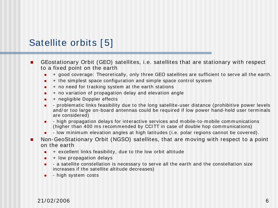
GEostationary Orbit (GEO) satellites, i.e. satellites that are stationary with respect to a fixed point on the earth
+ good coverage: Theoretically, only three GEO satellites are sufficient to serve all the earth.+ the simplest space configuration and simple space control system+ no need for tracking system at the earth stations+ no variation of propagation delay and elevation angle+ negligible Doppler effects- problematic links feasibility due to the long satellite-user distance (prohibitive power levels and/or too large on-board antennas could be required if low power hand-held user terminals are considered)- high propagation delays for interactive services and mobile-to-mobile communications (higher than 400 ms recommended by CCITT in case of double hop communications) - low minimum elevation angles at high latitudes (i.e. polar regions cannot be covered).
Non-GeoStationary Orbit (NGSO) satellites, that are moving with respect to a point on the earth
+ excellent links feasibility, due to the low orbit altitude+ low propagation delays- a satellite constellation is necessary to serve all the earth and the constellation size increases if the satellite altitude decreases)- high system costs

21/02/2006 7
Satellite Orbits
Highly Elliptical Orbit (HEO)+ high elevation angles (55-60°) for European coverage, due to the orbital location of the apogee;+ possibility of tailoring the system to cover specific regions of the earth with a limited number of satellites.- problematic links feasibility (even higher than in the GEO case) due to the considerable altitude of the satellites- big on-board antennas (6 meters or more) required - HEO satellites are not suitable for a global coverage;
LOOPUS (quasi-geostationary Loops in Orbit Occupied Permanently by UnstationarySatellites) is a HEO orbit characterized by an apogee altitude of 39,700 km and a perigee altitude of 1,250 km, with orbital plane inclination of 63.4°.
21/02/2006 8
Satellite orbits: LEO, MEO, GEO
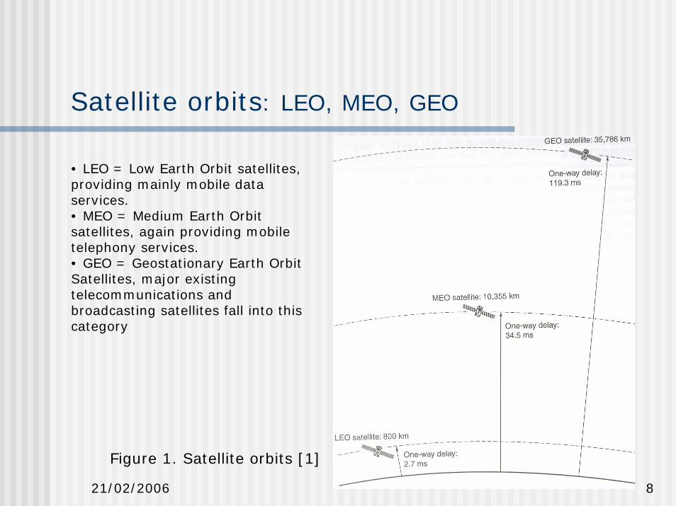
• LEO = Low Earth Orbit satellites, providing mainly mobile data services.• MEO = Medium Earth Orbit satellites, again providing mobile telephony services.• GEO = Geostationary Earth Orbit Satellites, major existing telecommunications and broadcasting satellites fall into this category
Figure 1. Satellite orbits [1]
21/02/2006 9
Satellites - Satellite subsystems
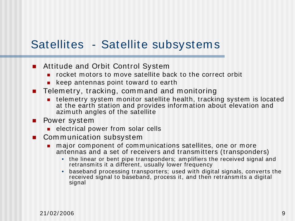
Attitude and Orbit Control Systemrocket motors to move satellite back to the correct orbitkeep antennas point toward to earth
Telemetry, tracking, command and monitoringtelemetry system monitor satellite health, tracking system is located at the earth station and provides information about elevation and azimuth angles of the satellite
Power systemelectrical power from solar cells
Communication subsystemmajor component of communications satellites, one or more antennas and a set of receivers and transmitters (transponders)
• the linear or bent pipe transponders; amplifiers the received signal and retransmits it a different, usually lower frequency
• baseband processing transporters; used with digital signals, converts the received signal to baseband, process it, and then retransmits a digital signal
21/02/2006 10
System Noise Temperature and G/T ratio
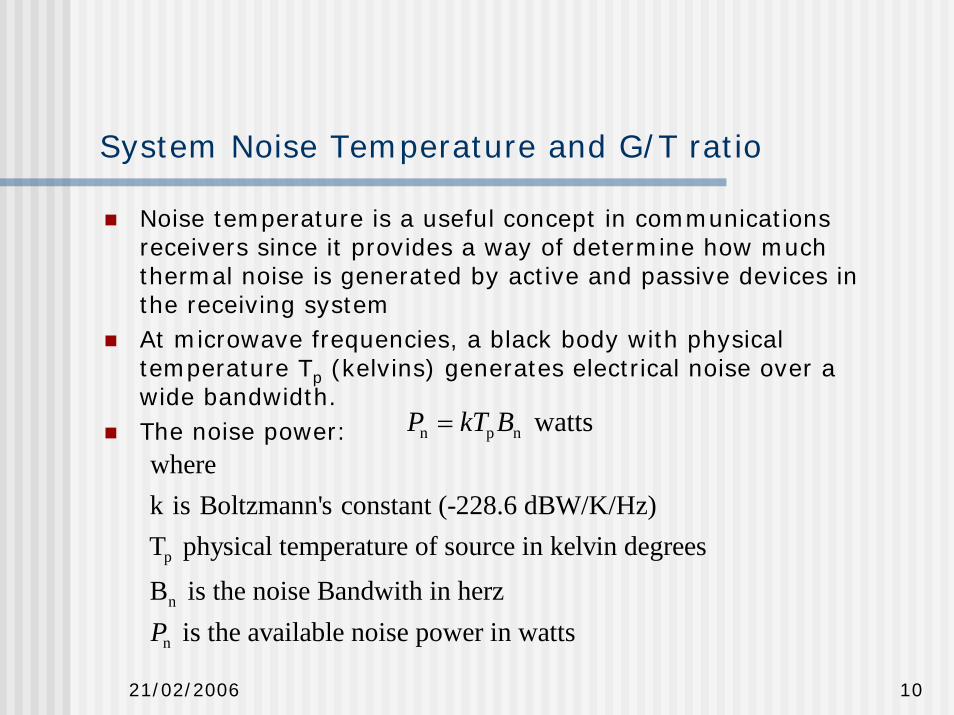
Noise temperature is a useful concept in communications receivers since it provides a way of determine how much thermal noise is generated by active and passive devices in the receiving systemAt microwave frequencies, a black body with physical temperature Tp (kelvins) generates electrical noise over a wide bandwidth.The noise power: n p n wattsP kT B=
p
n
n
k is Boltzmann's constant (-228.6 dBW/K/Hz)T physical temperature of source in kelvin degreesB is the noise Bandwith in herz
is the available noise power in wattsP
where

21/02/2006 11
G/T ratio
The sensitivity of a radio telescope is a function of many factors including antenna gain (G) and system noise temperature (T)Ts is the total system noise temperature (in degrees Kelvin) and is equal to the sum of the noise generated in the receiving system (Tr) and the noise delivered from the antenna (Ta) when the antenna is looking at a region of the sky free of strong sources. Ta includes the galactic background temperature as well as additional noise picked up by the antenna side lobes viewing the earth at ambient temperature.The receiving system temperature (Tr) is related to the system noise factor (FN) by:
Tr = (NF - 1 )*T0 (1)where the noise factor (NF) is systems noise figure:
NF=(S/N)in /(S/N)outand T0 is the reference temperature used to calculate the standard noise figure (usually 290 K)

21/02/2006 12
G/T ratio II – Practical case [6]
The principle behind determination of G/T is to measure the increase in noise power which occurs when the antenna is pointed first at a region of cold sky and then moved to a strong source of known flux density -usually the sun. This ratio of received power is known as the Y-factor.
Y= Psun / Pcold skyThe following equation shows the relationship between G/T, the measured Y-factor, and the value of solar flux (F) at the observing frequency:
G/T = (Y - 1) * 8 * pi * k * L / (F * Lam^2)where Y = sun noise rise expressed as a ratio (not dB)k = Boltzmann's constant (1.38 *10^-23 joules/deg K)L = beam size correction factorLam = wavelength in meters (at the operating frequency fo)F = solar flux at fo in watts / meter^2 / HzIf the dish has a beamwidth larger than 2 or 3 degrees the L can be set L=1 and forget about next equation.
L = 1 + 0.38 (Ws / Wa)^2where:Ws = diameter of the radio sun in degrees at foWa = antenna 3 dB beamwidth at fo

21/02/2006 13
G/T ratio III
The diameter of the radio sun (Ws) is frequency dependent. You can assume a value of 0.5 degrees for frequencies above 3000 MHz, 0.6 degrees for 1420 MHz, and 0.7 degrees for 400 MHz.USAF Space Command runs a worldwide solar radio monitoring network with stations in Massachusetts, Hawaii, Australia, and Italy. These stations measure solar flux density (F) at 245, 410, 610, 1415, 2695, 4995, 8800, and 15400 MHz. If you are operating near one of these eight "standard" frequencies then you can use the reported flux density.
When operating between two given frequencies then interpolate between flux densities at the lower and higher frequencies. The best interpolation scheme is to graph the flux density at several frequencies and use a curve fitting routine to determine the flux density at your operating frequency. The solar flux density obtained from the USAF must be multiplied by 10^-22 in order to get the units correct for use in equation (4). In other words, if the 1415 MHz solar flux density is 98 *10^-22 watts/meter^2/Hz, the operator may simply state "the solar flux at 1415 Mhz is 98".

21/02/2006 14
Satellite Link Design
The four factors related to satellite system design:1. The weight of satellite2. The choice frequency band3. Atmospheric propagation effects 4. Multiple access techniqueThe major frequency bands are 6/4 GHz, 14/11 GHz and 30/20 GHz (Uplink/Downlink)At geostationary orbit there is already satellites using both 6/4 and 14/11 GHz every 2˚(minimum space to avoid interference from uplink earth stations) -> Additional satellites higher BWLow earth orbit (LEO) & medium earth orbit (MEO) satellite systems are closer and produces stronger signals but earth terminals need omni directional antennasThe design of any satellite communication is based on
meeting of minimum C/N ratio for a specific percentage of timecarrying the maximum revenue earning traffic at minimum cost
21/02/2006 15
Link budgets
C/N ratio calculation is simplified by the use of link budgetsevaluation the received power and noise power in radio linkthe link budget must be calculated for individual transponder and for each linkWhen a bent pipe transponder is used the uplink and down link C/N rations must be combined to give an overall C/N

21/02/2006 16
Satellite Link Design – Example of Satellite Link Budget
Table 1 C-band GEO Satellite link budget in clear air. [1]
Table 2 C-band GEO Satellite link
budget in rain. [1]
21/02/2006 17
Satellite Link Design – Downlink Received Power
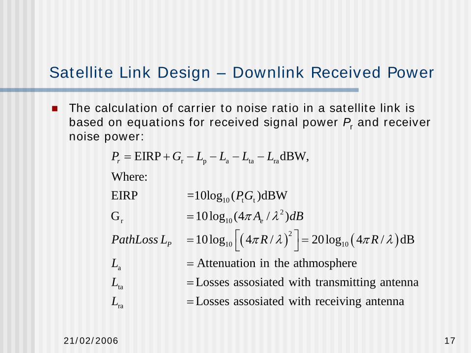
The calculation of carrier to noise ratio in a satellite link isbased on equations for received signal power Pr and receiver noise power:
( ) ( )
r p a ta ra
10 t t2
r 10
210 10
a
ta
ra
EIRP dBW,
Where:EIRP =10log ( )dBW
G 10log (4 / )
10log 4 / 20log 4 / dB
Attenuation in the athmosphereLosses assosiated with transmitting antennaLoss
r
e
P
P G L L L L
PG
A dB
PathLoss L R R
LLL
π λ
π λ π λ
= + − − − −
=
⎡ ⎤= =⎣ ⎦=== es assosiated with receiving antenna

21/02/2006 18
Satellite Link Design – Downlink Noise Power
A receiving terminal with a system noise temperature TsK and a noise bandwidth Bn Hz has a noise power Pnreferred to the output terminals of the antenna where
The receiving system noise power is usually written in decibel units as
n s n wattsP kT B=
s n
s
n
dBW,wherek is Boltzmann's constant (-228.6 dBW/K/Hz)T is the system noise temperature in dBKB is the noise Bandwith of the receiver in dBHz
N k T B= + +
21/02/2006 19
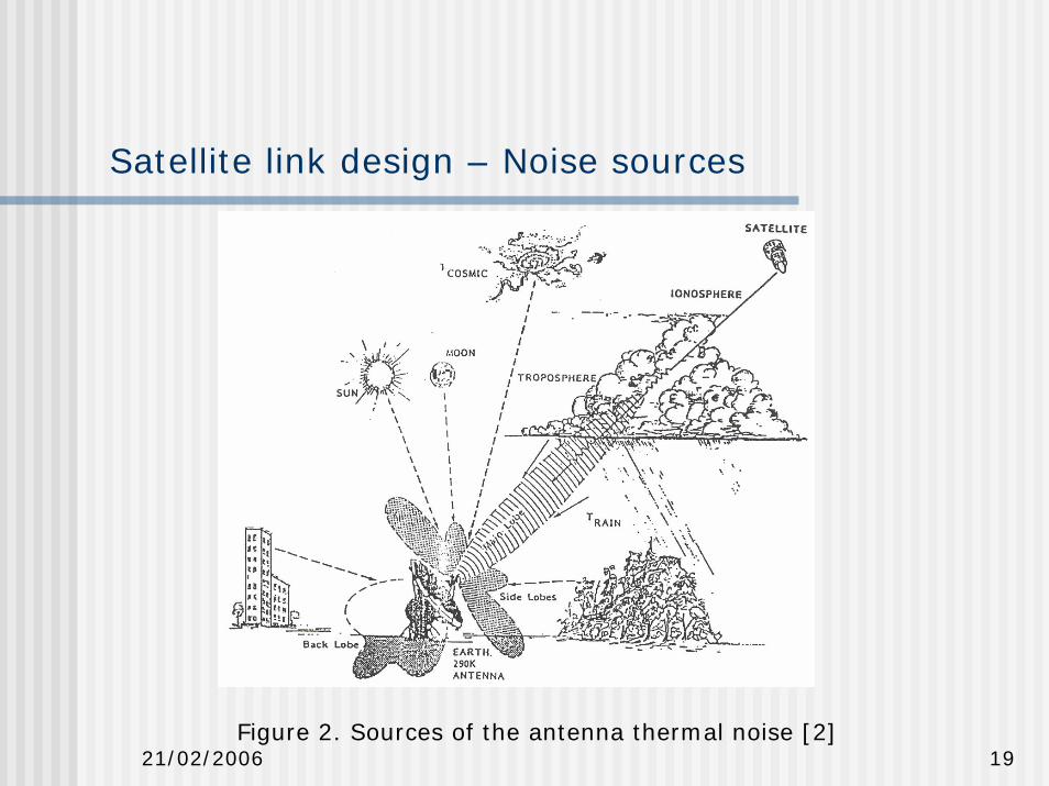
Satellite link design – Noise sources
Figure 2. Sources of the antenna thermal noise [2]

21/02/2006 20
Satellite link design - Uplink
Uplink design is easier than the down link in many casesearth station could use higher power transmitters
Earth station transmitter power is set by the power level required at the input to the transporter, either
a specific flux density is required at the satellitea specific power level is required at the input to the transporter
analysis of the uplink requires calculation of the power level at the input to the transponder so that uplink C/N ratio can be foundWith small-diameter earth stations, a higher power earth station transmitter is required to achieve a similar satellite EIRP.
interference to other satellites rises due to wider beam of small antenna
Uplink power control can be used to against uplink rain attenuation

21/02/2006 21
Propagation Effects and their impact
Many phenomena causes lead signal loss on through the earths atmosphere:
Atmospheric Absorption (gaseous effects)Cloud Attenuation (aerosolic and ice particles)Tropospheric Scintillation (refractive effects)Faraday Rotation (an ionospheric effect)Ionospheric Scintillation (a second ionospheric effect)Rain attenuationRain and Ice Crystal Depolarization
The rain attenuation is the most important for frequencies above10 GHz
Rain models are used to estimate the amount of degradation (or fading) of the signal when passing through rain.Rain attenuation models: Crane 1982 & 1985; CCIR 1983; ITU-R P.618-5(7 & 8)
21/02/2006 22
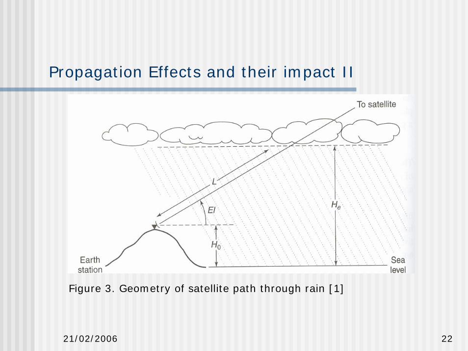
Propagation Effects and their impact II
Figure 3. Geometry of satellite path through rain [1]

21/02/2006 23
Annual cumulative attenuation
Figure 4. Annual cumulative attenuation distributions measured in Metsähovi, Kirkkonummi

21/02/2006 24
Case DVB-S: Broadcast Satellites
DVB-S (Digital Video Broadcasting)Geosynchronous orbitDVB-S uses QPSK modulation
Satellite locations are specified as degree of longitude:- ASTRA 1 = 6 satellites: 19.2°E- Hot Bird = 5 satellites: 13°E- Thor: 0.8°WDVB-S2 is a newer specification of the standard, ratified by ETSI in March 2005.
Adaptive coding to optimize the use of satellite transponders.4 modulation modes: QPSK, 8PSK (used in non-linear transponders near to saturation); 16APSK and 32APSKvideo codec has also been changed from MPEG-2 to H.264 (a.k.a. MPEG-4 Part 10)

21/02/2006 25
CASE DVB-S : Error correction
OFDMOFDM
Bit/ByteBit/Byte
ConvolutionalCode
ConvolutionalCode
DVB l =12DVB l =12
Reed SolomonRS(204, 188, T=8) Reed Solomon
RS(204, 188, T=8)
DVB-T
QAMQAM
DVB l =12DVB l =12
Reed SolomonRS(204, 188, T=8) Reed Solomon
RS(204, 188, T=8)
DVB-C
QPSKQPSK
ConvolutionalCode
ConvolutionalCode
DVB l =12DVB l =12
Reed SolomonRS(204, 188, T=8) Reed Solomon
RS(204, 188, T=8)
DVB-S
RF modulation
Inner interleaver
Inner coding(FEC)
Outer interleaver
Outer coder
Figure 5. Error correction in DVB systems. At the receiving side in the typical bit error ratio after QPSK demodulation is 10-1...10-2, after inner decoding 10-4
and after outer decoder 10-11. [3] & [4]
21/02/2006 26
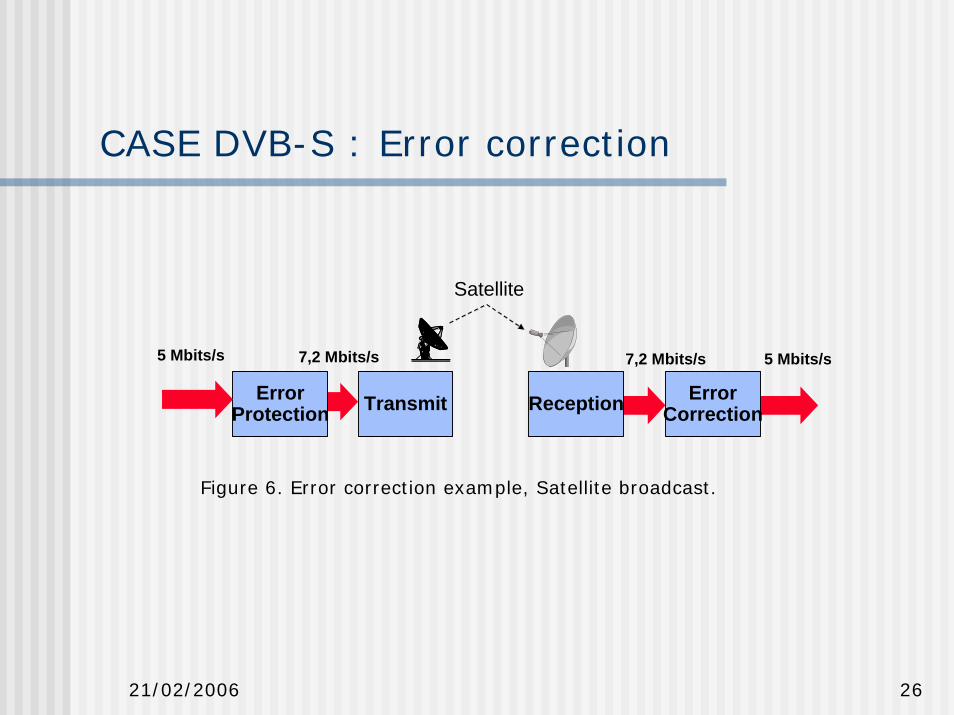
CASE DVB-S : Error correction
ErrorProtection Transmit Reception Error
Correction
5 Mbits/s 7,2 Mbits/s 7,2 Mbits/s 5 Mbits/s
Satellite
Figure 6. Error correction example, Satellite broadcast.

21/02/2006 27
References
1. Prat, Bostian, Allnut, Satellite Communications, Secondedition, John Wiley & Sons Inc. 2003
2. Tervonen, S-92.121 Satelliittitietoliikenne, Edita PrimaOy, Opetusmoniste 2002,
3. Ristilä, S-72.210 Yleisradioverkkojen jakelutekniikka, Edita Prima Oy, 2001
4. Vermasvuori, Digitaaliset järjestelmät, Yle/Jakelutekniikka 1996.
5. COST 227 Final report, Integrated Space / Terrestrial Mobile Networks, 1995
6. http://www.setileague.org/articles/g-t.htm

21/02/2006 28
Homework
1. An earth station antenna has diameter of 25 m, has an overall efficiency of 72 % and is used to receive signal at 4100 MHz. At this frequency the system noise temperature is 80 K when the antenna points at the satellite at the elevation angle of 28o
What is earth station G/T ratio under these conditions?


![Satellite communications[1]](https://static.fdocuments.in/doc/165x107/588ae6481a28abab6c8b6391/satellite-communications1.jpg)