
REVIEW OF SLOPE SURFACE DRAINAGE WITH REFERENCE · PDF fileREVIEW OF SLOPE SURFACE DRAINAGE...
69
REVIEW OF SLOPE SURFACE DRAINAGE WITH REFERENCE TO LANDSLIDE STUDIES AND CURRENT PRACTICE GEO REPORT No. 210 T.H.H. Hui, H.W. Sun & K.K.S. Ho GEOTECHNICAL ENGINEERING OFFICE CIVIL ENGINEERING AND DEVELOPMENT DEPARTMENT THE GOVERNMENT OF THE HONG KONG SPECIAL ADMINISTRATIVE REGION
Transcript of REVIEW OF SLOPE SURFACE DRAINAGE WITH REFERENCE · PDF fileREVIEW OF SLOPE SURFACE DRAINAGE...
REVIEW OF SLOPE SURFACE DRAINAGE WITH REFERENCE
TO LANDSLIDE STUDIES AND CURRENT PRACTICE
GEO REPORT No. 210
T.H.H. Hui, H.W. Sun & K.K.S. Ho
GEOTECHNICAL ENGINEERING OFFICE
CIVIL ENGINEERING AND DEVELOPMENT DEPARTMENT
THE GOVERNMENT OF THE HONG KONG
SPECIAL ADMINISTRATIVE REGION
REVIEW OF SLOPE SURFACE DRAINAGE WITH REFERENCE
TO LANDSLIDE STUDIES AND CURRENT PRACTICE
GEO REPORT No. 210
T.H.H. Hui, H.W. Sun & K.K.S. Ho
This report was originally produced in February 2006 as GEO Landslide Study Report No. LSR 1/2006

- 2 -
© The Government of the Hong Kong Special Administrative Region First published, August 2007 Prepared by: Geotechnical Engineering Office, Civil Engineering and Development Department, Civil Engineering and Development Building, 101 Princess Margaret Road, Homantin, Kowloon, Hong Kong.

- 3 -
PREFACE
In keeping with our policy of releasing information which may be of general interest to the geotechnical profession and the public, we make available selected internal reports in a series of publications termed the GEO Report series. The GEO Reports can be downloaded from the website of the Civil Engineering and Development Department (http://www.cedd.gov.hk) on the Internet. Printed copies are also available for some GEO Reports. For printed copies, a charge is made to cover the cost of printing. The Geotechnical Engineering Office also produces documents specifically for publication. These include guidance documents and results of comprehensive reviews. These publications and the printed GEO Reports may be obtained from the Government’s Information Services Department. Information on how to purchase these documents is given on the second last page of this report. R.K.S. Chan
Head, Geotechnical Engineering Office August 2007
- 4 -
FOREWORD
This report presents the findings of a review of the current practice in respect of design and detailing of slope surface drainage provisions, with particular reference to lessons learnt from the relevant landslide studies. Areas that deserve attention are highlighted.
Mr T.H.H. Hui and Dr H.W. Sun of the Landslip
Preventive Measures Division 1 assisted in preparing the report. Maunsell Geotechnical Services Limited, the 2005 landslide investigation consultants, provided general support. The draft report was reviewed by Mr T.M.F. Lau of the Landslip Preventive Measures Division 1. All contributions are gratefully acknowledged.
K.K.S. Ho Chief Geotechnical Engineer/LPM Division 1
- 5 -
CONTENTS
Page No. Title Page 1 PREFACE 3 FOREWORD 4 CONTENTS 5 1. INTRODUCTION 7 2. SOURCES OF INFORMATION 8 3. LANDSLIDE INCIDENTS INVOLVING INADEQUATE 8 SURFACE DRAINAGE
3.1 General 8
3.2 The 5 May 2003 Washout Failures on a Fill Slope below 8 South Lantau Road
3.3 Distress of a Fill Slope below Shek O Road in November 2003 9
3.4 The July 2001 Landslide on a Fill Slope below Broadwood 10 Road, Happy Valley
3.5 The 2 July 1997 Landslides at the Tao Fung Shan Christian 10 Cemetery, Sha Tin
3.6 The 9 June 1998 Landslide on a Fill Slope below 11 Au Tau Village Road, Tseung Kwan O
3.7 The 24 August 2000 Landslide on a Hillside above Bowen Road 11
3.8 The 24 August 1999 Landslide on a Hillside above 12 Mount Davis Road
3.9 The 23 August 1999 Landslide on a Cut Slope below 12 Yin Hing Temple, Lantau
3.10 The June 2001 Landslide on a Cut Slope at Route Twisk 13
3.11 The 24 August 2000 Landslides on Disturbed Terrain below 13 Tai Hang Road
3.12 The 24 August 2000 Landslide on a Hillside below 14 Tai Tam Road 4. PUBLISHED GUIDANCE ON SURFACE DRAINAGE OF SLOPES 14

- 6 -
Page No. 5. SOME OBSERVATIONS ON LOCAL DESIGN PRACTICE FOR 17 SIZING OF SURFACE DRAINAGE CHANNELS ON SLOPES 6. EXAMPLES OF INADEQUATE SLOPE SURFACE DRAINAGE 19 PROVISIONS AS OBSERVED IN PRACTICE 7. AREAS REQUIRING ATTENTION 21 8. CONCLUSIONS 22 9. REFERENCES 23 LIST OF TABLES 26 LIST OF FIGURES 28 LIST OF PLATES 43 APPENDIX A: ITEMS FOR ATTENTION IN RESPECT OF 60 DETAILING OF SURFACE DRAINAGE PROVISIONS
- 7 -
1. INTRODUCTION
Studies undertaken under GEO’s systematic landslide investigation programme since 1997 have highlighted that inadequate surface drainage provisions can be a contributory factor in landslides and washouts. The effects of road drainage and road geometry, together with the role of adverse environmental factors, in causing roadside slope failures were highlighted by Au & Suen (1991; 2001a & 2001b). The importance of road drainage and regular maintenance was emphasized by the 1995 Shum Wan Road landslide, which resulted in two fatalities (GEO, 1996).
The importance of uncontrolled overland flow in triggering landslides or major washouts has also been demonstrated by a number of significant incidents that gave rise to major social disruption. These included the 1997 Mei Chung Court flooding incident (which involved uncontrolled overland flow due to partial blockage of a stream course by a footbridge, leading to major washout failures and inundation of a basement carpark (HAP, 1998a)), the 1997 Yau Kom Tau flooding incident (which involved overflow from a catchwater that was blocked by landslide debris, resulting in flooding and partial closure of Tuen Mun Highway (HAP, 1998b)), and the 2005 Lo Wai debris flood incident (which was caused by overflow from a catchwater that was blocked by landslide debris, resulting in havoc and temporary evacuation of a large number of people in Lo Wai Village).
The key landslide hazard scenarios associated with potential surface water drainage problems in Hong Kong are as follows (GEO, 2005):
(a) inadequate surface drainage provisions/detailing at
man-made slopes and stormwater drain inlets;
(b) unplanned/uncontrolled discharge of surface water from roads and paved platforms in developed areas, due to inadequate drainage provision upstream, blockage of drains, diversion of surface water flow by landslide debris and unfavourable changes in environmental setting, which has not been catered for in surface drainage design in the downstream area;
(c) overflow of stormwater from catchwater; and
(d) overflow of stormwater from drainage lines, due to blockage
of drainage lines or blockage of catchpits/stormwater drains at drainage lines by landslide debris from hillside failures.
An example of an adverse scenario that has been observed in practice from time to
time is where water is issuing under pressure out of the downhill drainage system beneath steeply sloping roads during intense rainfall, due to the inability to cope with the uphill hydraulic head, i.e. the drainage system itself becomes the hazard. Attention to surface drainage is called for, especially with a dense urban development on steep hilly terrain, in order to mitigate the associated hazards that can be brought about by uncontrolled surface water flow.
- 8 -
The present review covers principally the design and detailing aspects of surface drainage provisions on slopes. The scope of the review comprises an overview of the key findings of studies of selected landslide incidents, together with an appraisal of the local practice in relation to the design and construction of slope surface drainage, as well as pertinent observations made during slope inspections. The objective of the review is to identify areas that deserve further attention and improvement. Landslides due to inadequate temporary drainage provisions during slope works have been reviewed by Sun & Tsui (2003), and specific areas that warrant attention have been identified. This will not be repeated here.
In this report, the findings of the review are presented and areas that deserve attention
are highlighted.
2. SOURCES OF INFORMATION
The sources of information referred to for the present review include the following:
(a) GEO’s Landslide Incident Reports and Landslip Cards,
(b) GEO’s Landslide Study Reports (LSRs), (c) annual reports on diagnostic review of landslides published
by the GEO for reported landslide incidents since 1997,
(d) relevant GEO files and reports, including LPM Stage 3 Study reports, and
(d) selected Engineer Inspection reports obtained from the slope
maintenance departments. 3. LANDSLIDES INCIDENTS INVOLVING INADEQUATE SURFACE DRAINAGE
3.1 General
Eleven notable landslide incidents involving inadequate surface drainage provisions have been reviewed. The pertinent observations are summarised below to provide some insight on what one should look out for in assessing drainage provisions for slopes. The readers are strongly encouraged to consult the investigation reports for the details of the individual landslide incidents.
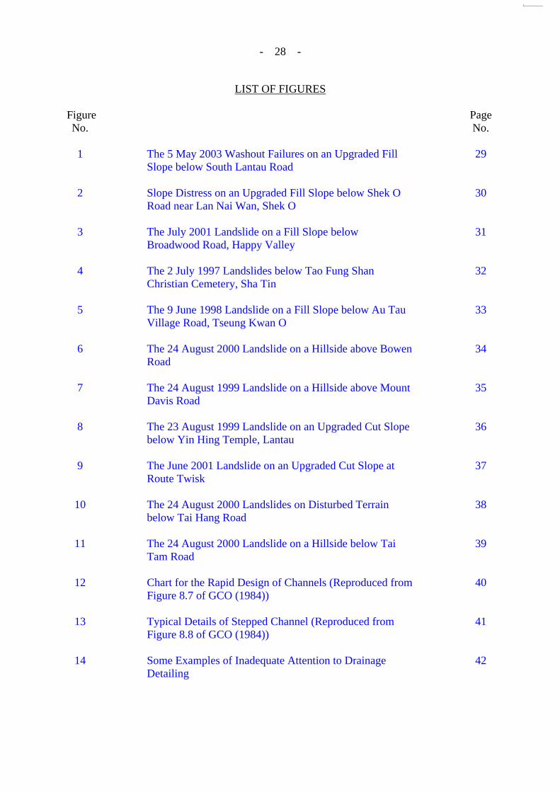
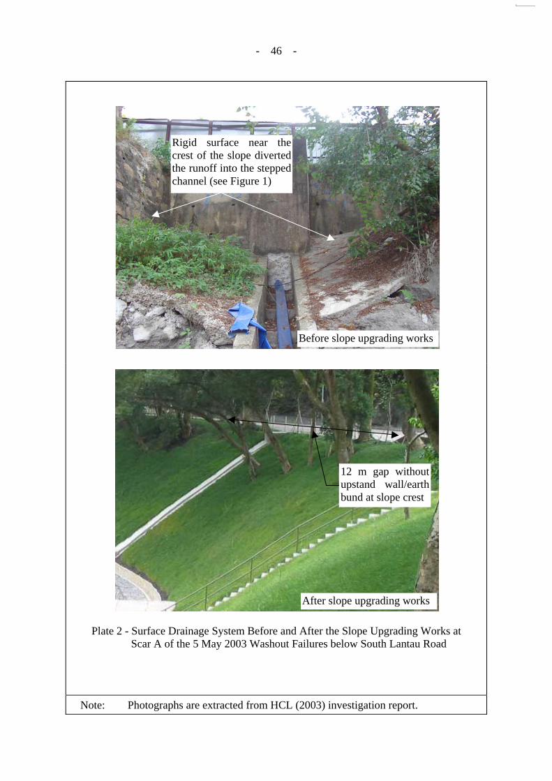
3.2 The 5 May 2003 Washout Failures on a Fill Slope below South Lantau Road
This case involved two major washout failures (with a total volume of about 150 m³), which occurred on a newly upgraded fill slope (HCL, 2003). The slope is located below a road bend, which is also the local low point of South Lantau Road above the crest (see Figure 1 and Plates 1 to 4). The slope was selected for upgrading because of a major washout failure that occurred in 1993.
- 9 -
The adverse environmental setting of the site, together with partial blockage of the prevailing road drainage system due to inadequate maintenance, led to the collection of a large volume of surface runoff along the road from a much bigger catchment than that assumed in the design calculations. As a result, the surface water flow on the road discharged through two local low points at the slope crest, which led to severe erosion of the fill slope by uncontrolled and concentrated surface runoff.
The situation was exacerbated by poor detailing and probably inadequate review
conducted during the construction of the slope drainage system (see Figure 1). One of the failure scars coincided with the location of a previous concrete apron below a low point of the road at the crest, which was downhill of an opening in the crest upstand wall that, in effect, served as an overflow system. As part of the slope upgrading works, the slope, including the concrete apron, was filled up and provided with a vegetated cover but the opening in the upstand wall at the crest was maintained. During heavy rainfall in May 2003 shortly after completion of slope upgrading works, the road above the slope crest was flooded. As a consequence, concentrated discharge occurred through the opening in the upstand wall, which resulted in severe erosion of the vegetated slope (see Figure 1 and Plate 2).
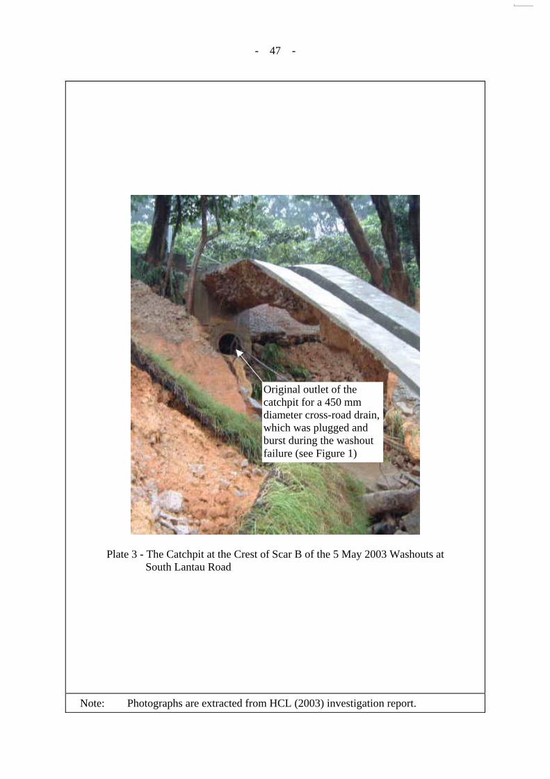
The other failure scar coincided with the outlet to an existing 450 mm diameter
cross-road stormwater culvert, which was plugged during the slope upgrading works. As part of the slope upgrading works, additional rockfill was placed on the slope behind a newly constructed toe retaining wall, and the pre-existing catchpit was correspondingly extended upward such that the raised outlet was connected to the new 300 mm stepped channel on the elevated slope surface. As a result of this detailing, the water flow from the cross-road culvert leading to this catchpit was expected to bend round and travel upward before discharging onto the slope drainage channel. Such a connection detailing probably reduced the discharge capacity of the system significantly, as evidenced by the observation of uncontrolled overflow of stormwater directly onto the carriageway from the catchpit located on the opposite side of the road. The overflow was discharged onto the subject fill slope, resulting in severe erosion.
This incident highlights the importance of giving due attention to the environmental
setting of the site in the design and detailing of slope drainage provisions, in particular the proper detailing of the connections between cross-road culverts and the slope drainage provisions. A comprehensive assessment of all the potential hazards affecting the performance of the slope surface drainage provisions should be undertaken, especially for vulnerable sites with an adverse environmental setting and a history of problems associated with surface water overflow.
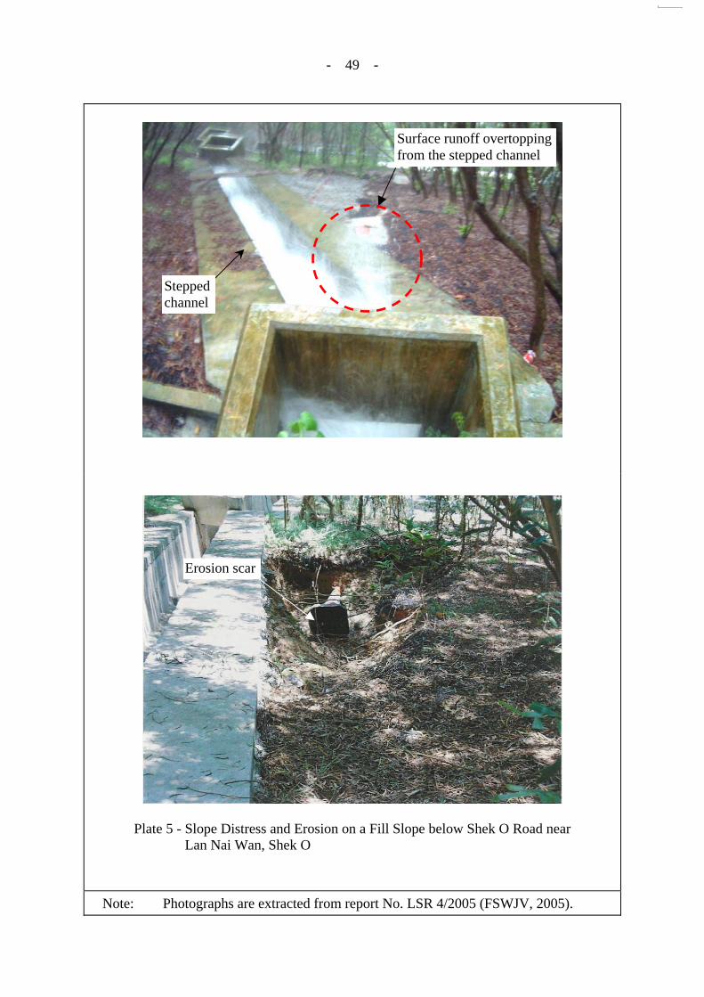
3.3 Distress of a Fill Slope below Shek O Road in November 2003
This case involved a minor washout failure (< 5 m³), which occurred on a newly upgraded fill slope. It transpired that this was a repeated problem since completion of the slope upgrading works. The erosion was observed during intense rainfall to be caused by significant overspilling from a stepped channel that runs obliquely down the slope face at about 30°. The principal cause of the overflow was due to a sudden change in the flow directions between the outlet of a cross-road culvert and a stepped channel on the slope (see Figure 2 and Plate 5).
- 10 -
The follow-up study (FSWJV, 2005) established that overspilling from the stepped channel was probably a result of the poor detailing of the catchpit/stepped channels, together with an under-estimation of the potential adverse effects of abrupt changes in the directions of surface water flow. Inadequate depth of the downslope side of the stepped channel, and lack of precautionary measures at the vulnerable location (such as provision of elevated sidewalls to the channel on the downslope side of the catchpit), may also have contributed to the uncontrolled overspilling.
This incident serves to highlight the importance of paying due attention to proper
detailing of slope drainage provisions and appropriate amendment of the detailing on site during slope works to suit the actual site conditions.
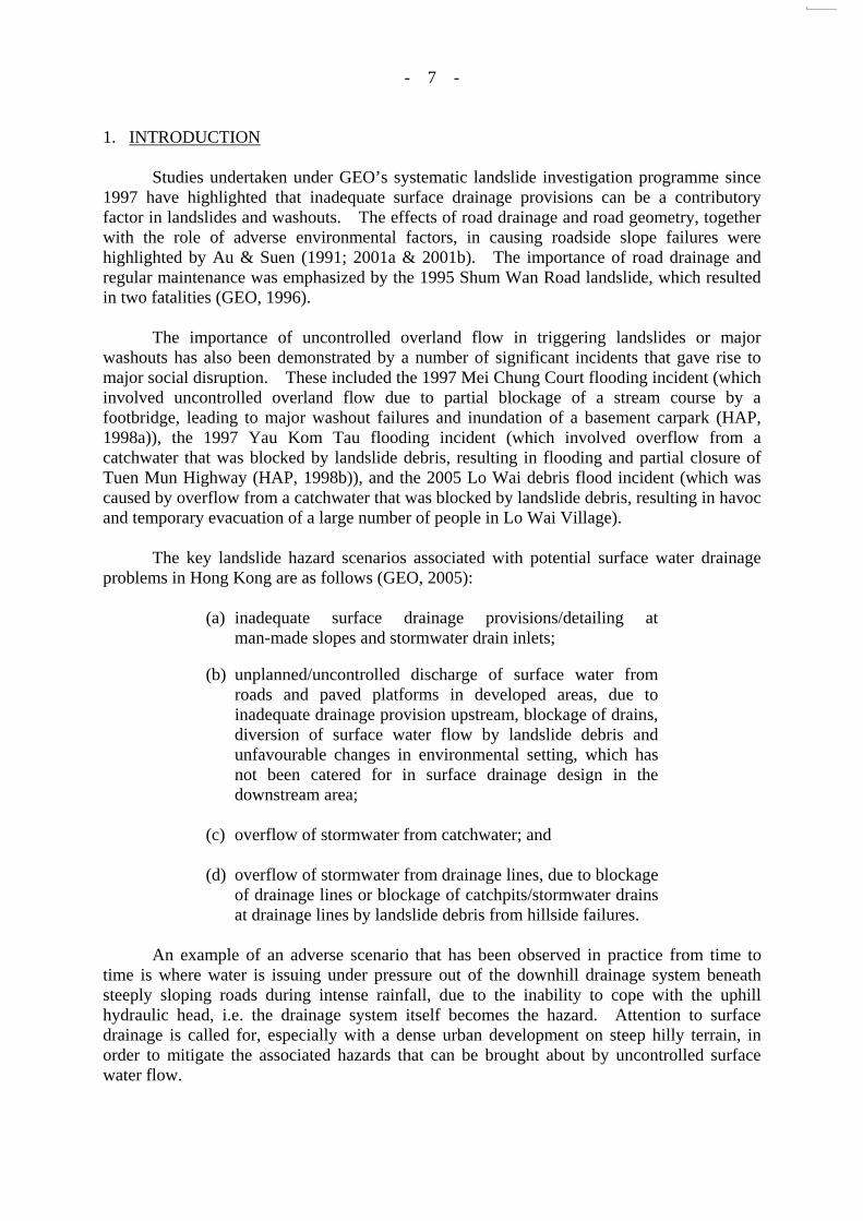
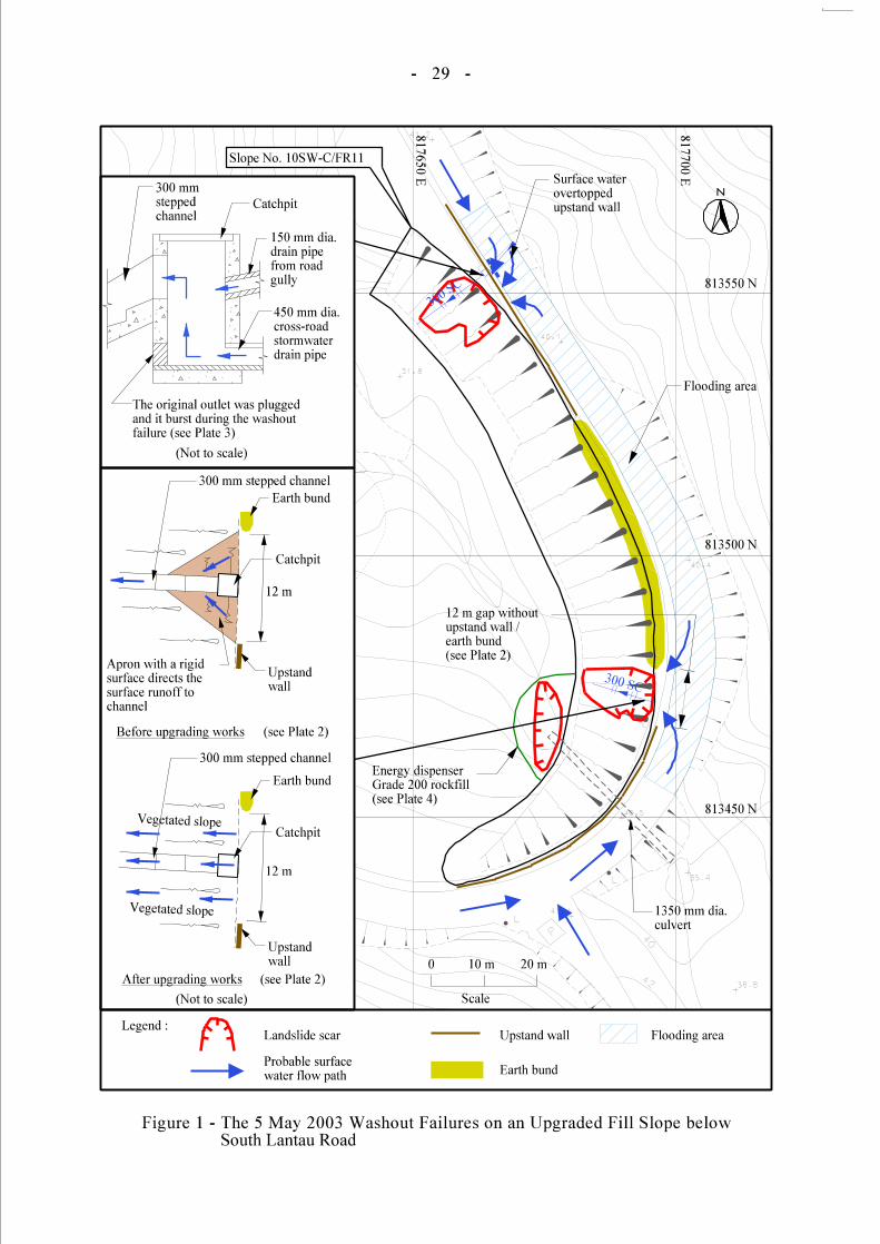
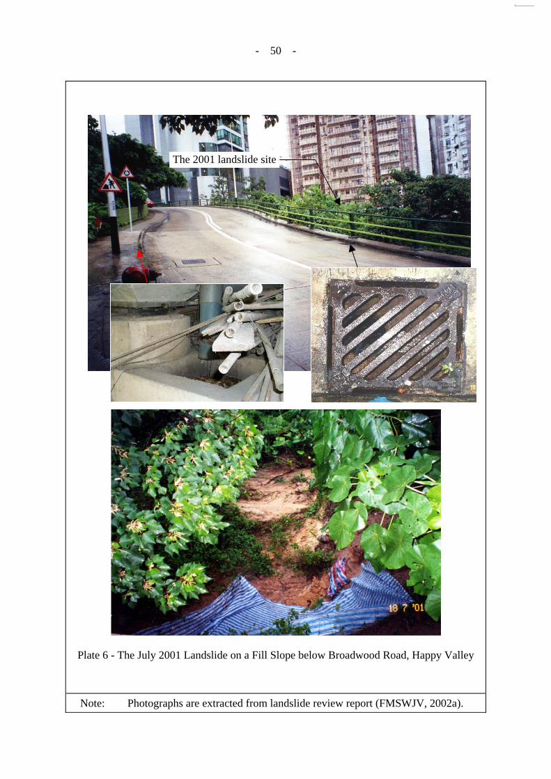
3.4 The July 2001 Landslide on a Fill Slope below Broadwood Road, Happy Valley
This case involved a major landslide (about 50 m³), which occurred on an engineered fill slope below a viaduct (see Figure 3 and Plate 6). Surface runoff collected by two roadside drainage inlets above the slope was directed to a catchpit at the crest of the subject fill slope through a down pipe. No traps or sumps were provided for the roadside gullies on the elevated road deck.
The follow-up study (FMSWJV, 2002a) established that the catchpit at the slope crest
was probably blocked at the time of the incident due to debris carried down from the roadside drainage inlets through the down pipe. Overflow and splashing of surface water from the catchpit were diagnosed as the key contributory factors to the failure. No precautionary measures, such as hard surface protection, were provided to the ground surface adjacent to the catchpit to mitigate erosion due to possible overflow from the catchpit.
This incident serves as a reminder that surface water collection systems should be
adequately protected against potential blockage and overspilling. Given a vulnerable arrangement as in this case, the need for precautionary measures, such as provision of hard surface protection to the slope supporting the catchpit against scouring and progressive undermining due to possible spillage, is called for, as any movement of the slope supporting the catchpit will result in differential settlement of the catchpit, which in turn will pull the down pipe off its connection to the roadside gully at the top. Once this happens, the runoff from the gully sump will flow vertically downwards from the bridge deck onto the bare slope below and is liable to trigger a large landslide.
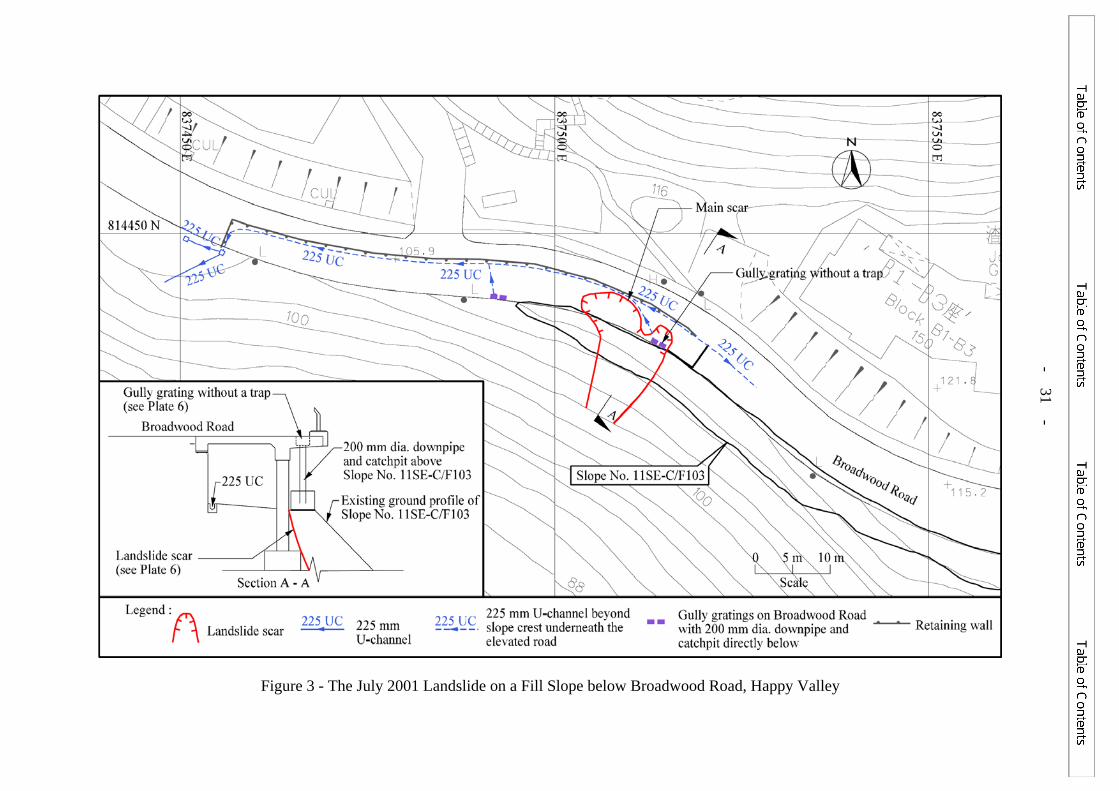
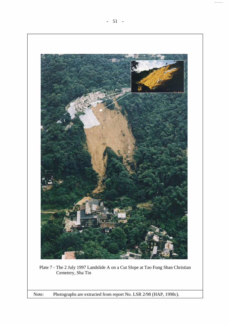
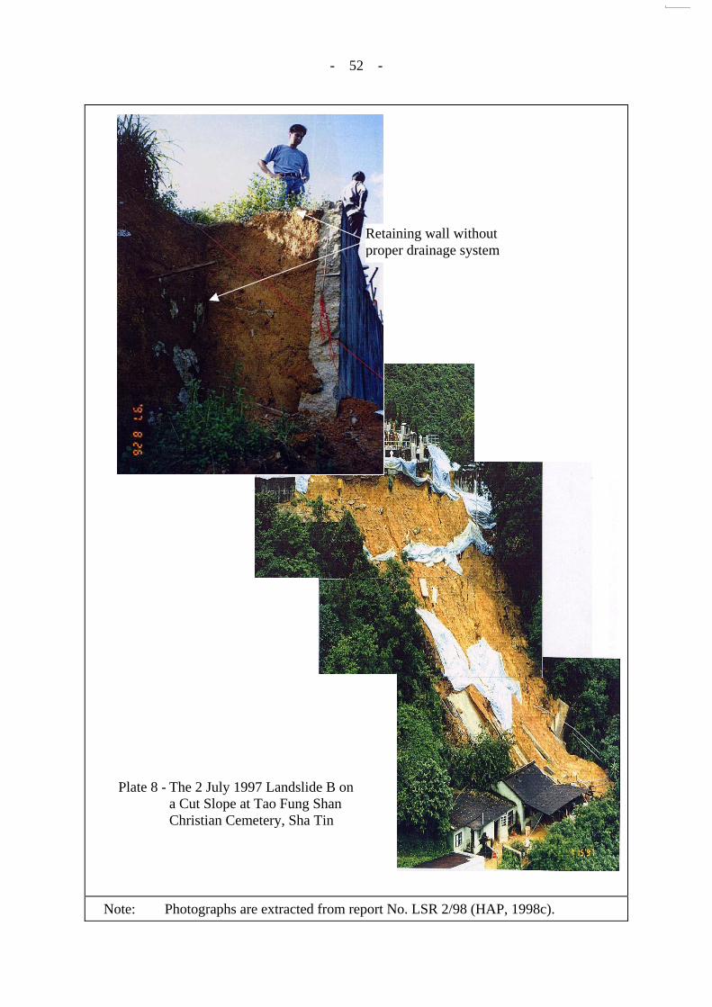
3.5 The 2 July 1997 Landslides at the Tao Fung Shan Christian Cemetery, Sha Tin
This case involved two major landslides (with a total volume of about 1,300 m³), which affected two non-engineered man-made slopes within a cemetery. Several abandoned buildings were severely damaged as a result of the landslides (see Figure 4 and Plates 7 and 8). No casualties were reported but a registered squatter structure with outstanding NDC recommendation was demolished by landslide debris and casualty was narrowly avoided in this ‘near-miss’ incident as the squatter structure happened to be unoccupied at the time.

- 11 -
The follow-up study (HAP, 1998c) revealed that the hilltop development above the source areas of the landslides was paved shortly before the failures. Illegal earthworks involving the construction of a substandard retaining wall, together with inadequate surface drainage provisions within the hilltop development leading to uncontrolled and concentrated surface runoff onto the downhill slopes, were the key contributory factors to the landslides.
These incidents highlight, inter alia, the importance of paying due attention to proper
surface drainage provisions to avoid uncontrolled discharge of surface runoff onto vulnerable downhill slopes, particularly for sites with changes in the ground surface cover that could significantly alter the surface runoff characteristics.
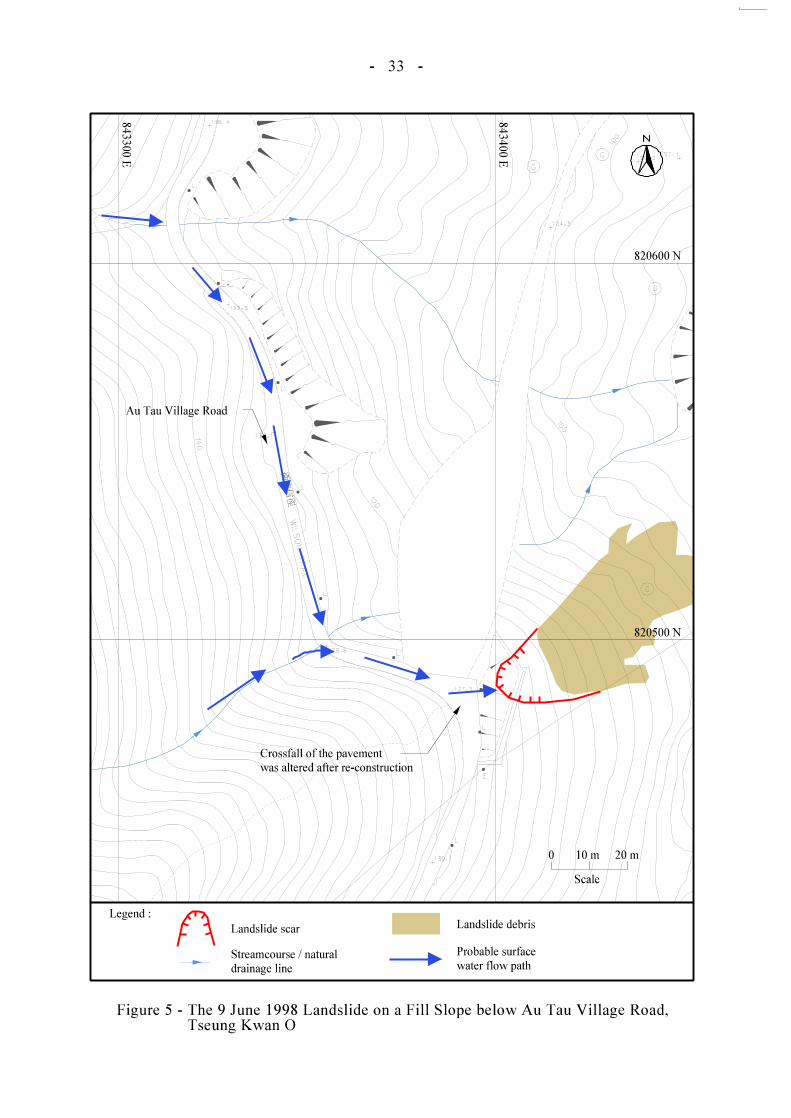
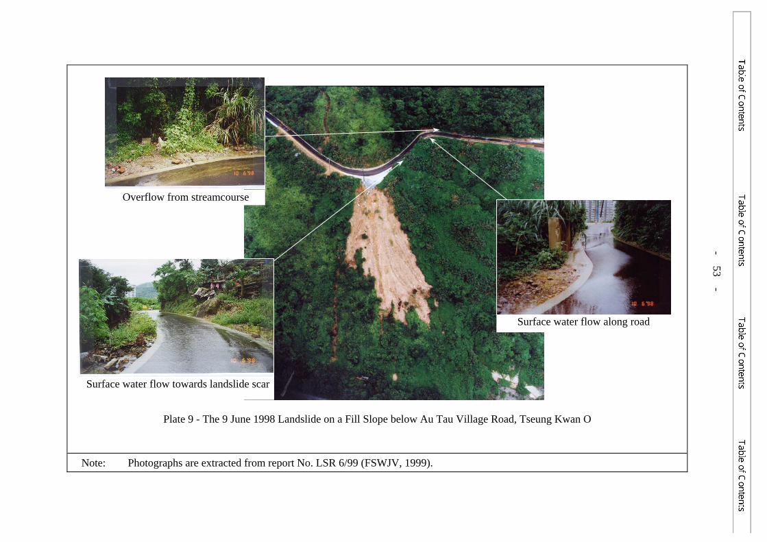
3.6 The 9 June 1998 Landslide on a Fill Slope below Au Tau Village Road, Tseung Kwan O
This incident comprised a major landslide (about 170 m³) involving the failure of an old fill slope below a minor access road (see Figure 5 and Plate 9). Uncontrolled overtopping of surface water from the access road at slope crest was diagnosed as a key contributory factor to the landslide (FSWJV, 1999).
The access road had no surface drainage provisions and the pavement was
reconstructed about three months before the landslide. During the reconstruction works, the crossfall of the pavement was altered. This, together with the road geometry, probably resulted in surface runoff being directed along the road towards the landslide site. Ponding of surface water was observed on the road after the landslide. Flows from the nearby streamcourses could also have played a contributory role in providing a possible additional source of water onto the road (see Figure 5). Overtopping of surface water from the crest area directly onto the loose fill below the road probably promoted surface erosion and concentrated water ingress into the ground mass resulting in the major landslide.
This incident highlights the potential impact of adverse changes in the environmental
condition of the upslope area, which could convey additional surface water towards the downhill area resulting in a slope failure.
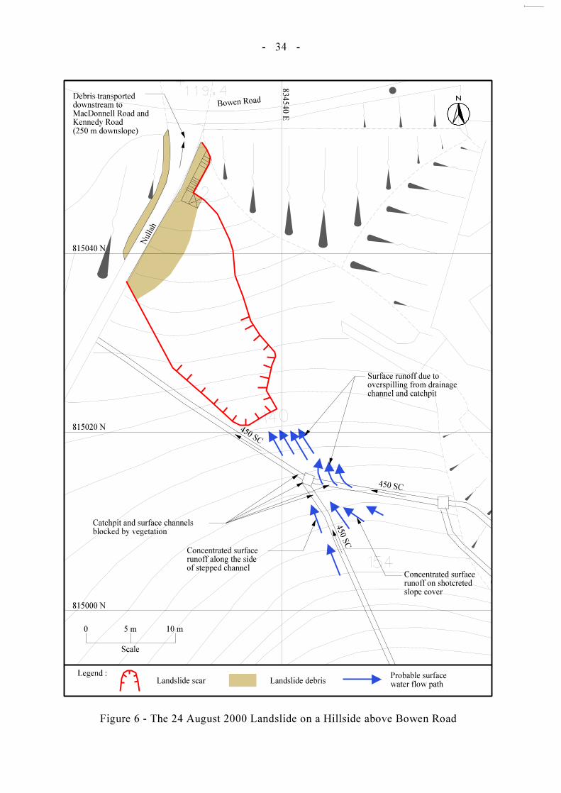
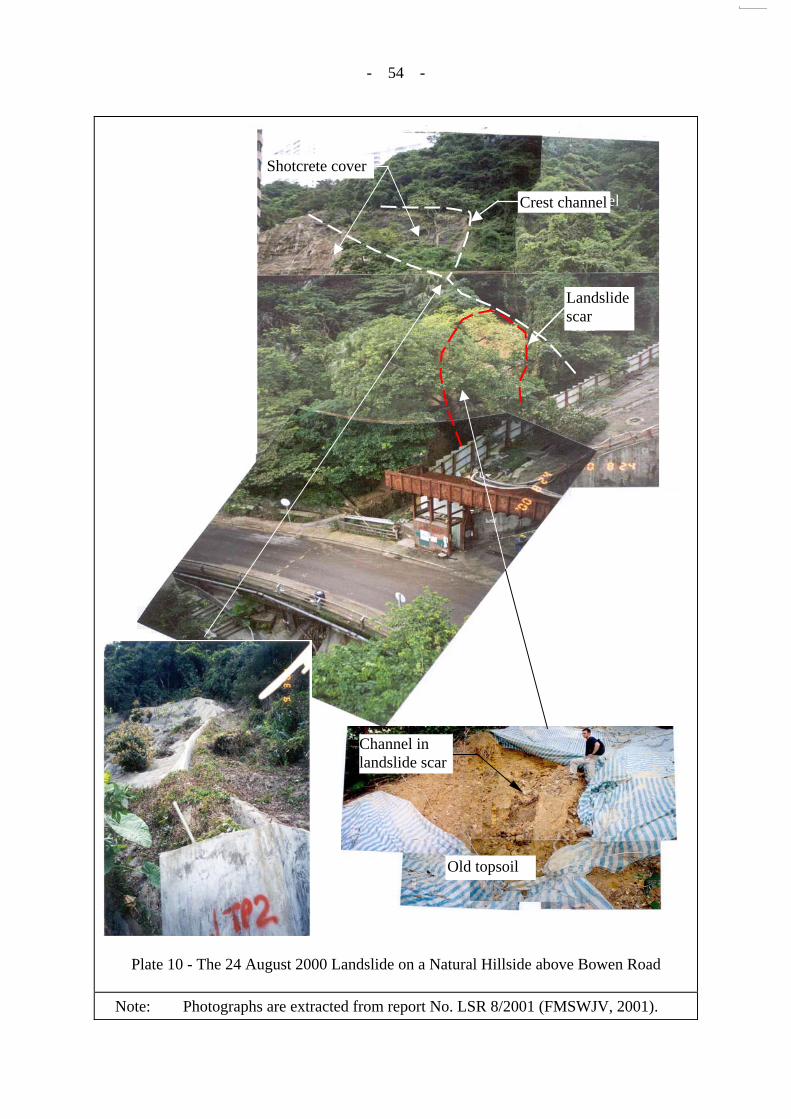
3.7 The 24 August 2000 Landslide on a Hillside above Bowen Road
This case involved a major landslide (about 120 m³), which occurred within a thin layer of old fill dumped on a steeply-sloping hillside. The landslide debris reached an adjacent nullah and became channelised and flowed downstream for about 250 m, causing havoc to the developed areas below (see Figure 6 and Plate 10).
The follow-up investigation (FMSWJV, 2001) revealed that, apart from direct
infiltration during intense rainfall, inadequate surface drainage provision was a key contributory factor to the failure. Two 450 mm stepped channels receiving surface runoff from the large catchment above were connected to the same catchpit and there was evidence of significant overspilling from the drainage channels during intense rainfall. No upstand walls were provided in the vicinity of the drainage connections to cope with possible splashing of surface runoff. Blockage of surface drainage provisions above the landslide site caused overflow and provided an additional source of water ingress into the landslide site. The drainage channels and a catchpit were observed to have been blocked by vegetation on
- 12 -
the day of the failure. There was also evidence of overland flow between the channel and the landslide scar, indicating that water had overspilled from the drainage system.
It was further observed that one of the two 450 mm stepped channels upstream of the catchpit above the failure scar protruded above the local ground surface by about 400 mm. As a result of this, some of the surface runoff on the hillside above this channel was probably directed along the outer face of the channel resulting in uncontrolled discharge of surface water and concentrated water ingress into the ground mass.
This landslide highlights the importance of proper detailing and construction of surface
drainage provisions, and the need for robust drainage detailing, especially for sites with a large catchment area and at vulnerable locations where overspilling is possible. It is also pertinent that no proper access to the upper part of the slope and the hillside was provided for maintenance.
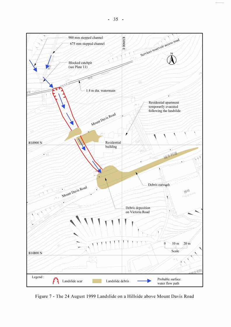
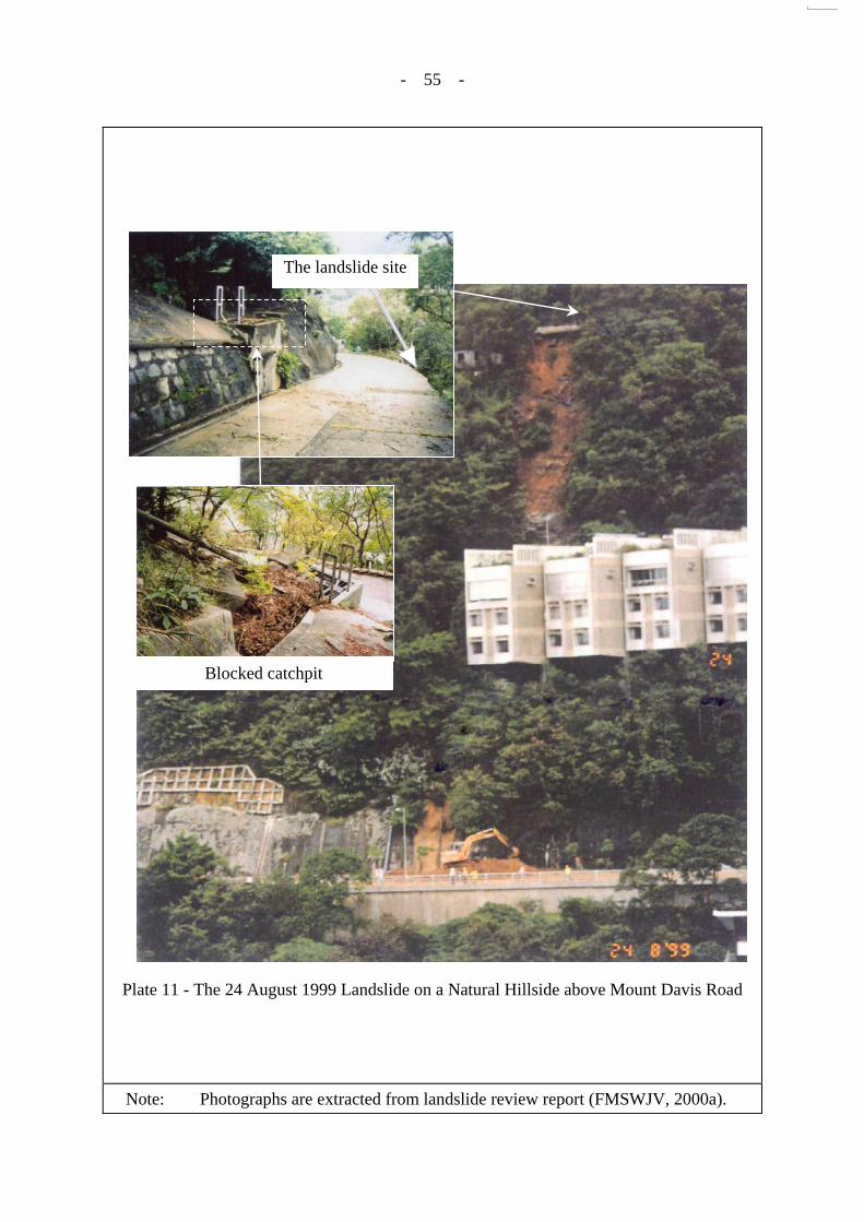
3.8 The 24 August 1999 Landslide on a Hillside above Mount Davis Road
This incident comprised a major landslide (about 200 m³) that occurred on a hillside below Mount Davis Road. The landslide debris travelled narrowly missed a residential building block in the downhill area. Following the failure, the occupants of the affected building block were evacuated temporarily. The landslide debris undermined a 1.4 m diameter pressurised watermain at the crown of the failure scar, which is an important trunk main for supplying potable water to the Hong Kong south areas (see Figure 7 and Plate 11).
The follow-up study (FMSWJV, 2000a) established that the landslide was associated
with the blockage of several catchpits along an access road directly above the landslide source area. This probably resulted in uncontrolled discharge of surface runoff from the fairly sizeable catchment above, and overspilling of surface water near a road bend probably led to concentrated water ingress into the hillside below, resulting in the major failure. Inadequate and poorly maintained surface water drainage provisions along the access road, together with lack of an upstand on the downhill side of the access road, were the probable key contributory factors to the landslide.
This incident highlights the importance of providing adequate road drainage, regular
maintenance and precautionary measures (e.g. provision of upstand) to minimise the possibility of uncontrolled overspilling of surface runoff at vulnerable locations, particularly where there is a sizeable catchment area.
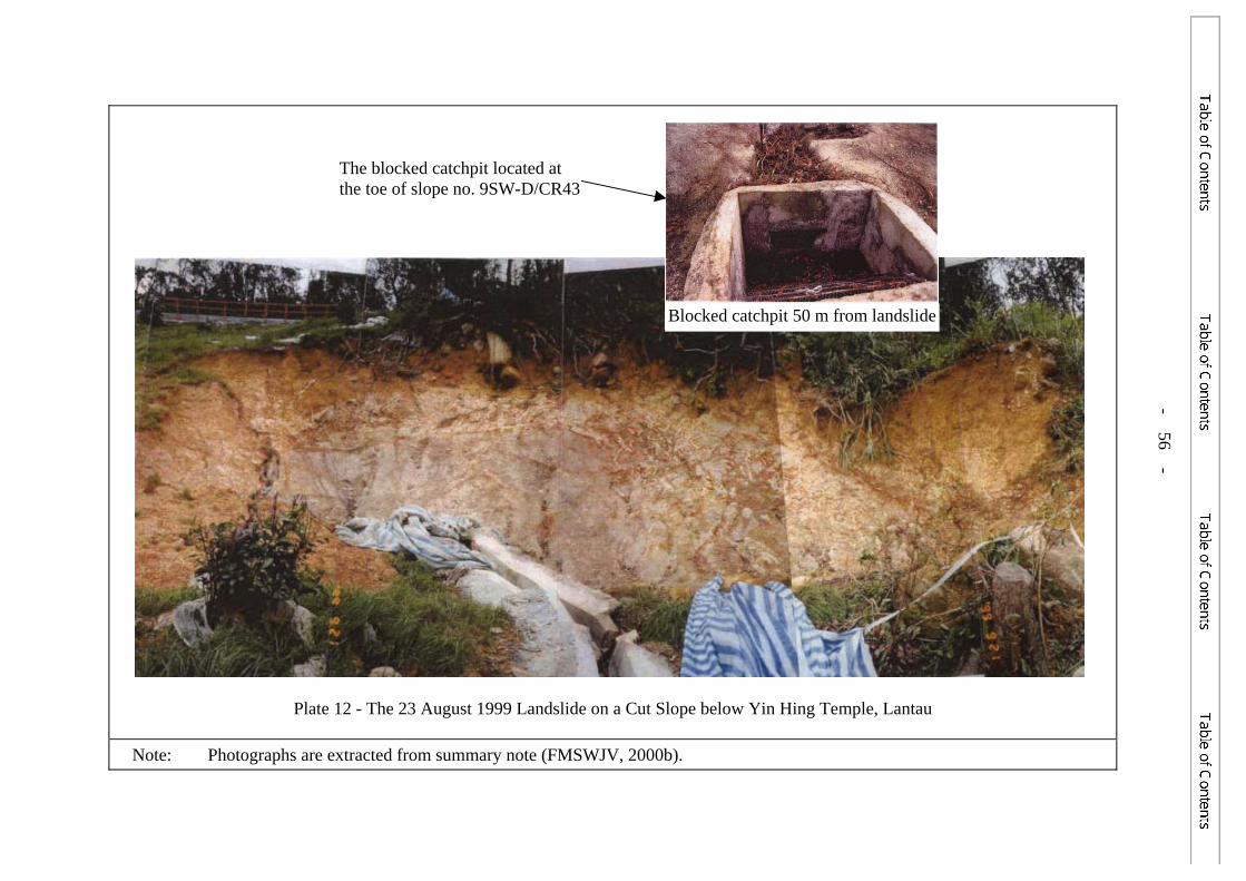
3.9 The 23 August 1999 Landslide on a Cut Slope below Yin Hing Temple, Lantau
This incident involved a major landslide (about 75 m³) that occurred on an engineered soil cut (FMSWJV, 2000b) during the first wet season after completion of slope upgrading works (see Figure 8 and Plate 12).
No surface drainage channels had been provided above the landslide site, probably
because the associated catchment area was considered to be insignificant. A stairway within the area above the crest of the subject cut slope probably acted as a conduit for surface water flow during intense rainfall and directed surface runoff towards the landslide site. This

- 13 -
would have resulted in surface erosion and concentrated water ingress into the ground mass, resulting in the major failure.
This incident serves as a reminder of the need to pay due attention in reviewing the environmental condition of the site setting and implement appropriate preventive or precautionary measures to mitigate the potential impact of concentrated surface water flow on a slope.
3.10 The June 2001 Landslide on a Cut Slope at Route Twisk
This incident involved a minor landslide (about 3 m³) that occurred on a newly upgraded soil cut slope. As part of the slope upgrading works, the pre-existing hard surface cover was replaced with a vegetated cover (see Figure 9 and Plate 13). No surface drainage channel was provided on a 3 m wide vegetated berm above the location of the landslide to intercept potential surface runoff from the upper slope batter.
The follow-up study (Hui, 2002) established the presence of a local shallow depression
on the vegetated berm directly above the landslide source area. Enhanced and concentrated water ingress into the ground mass from this local low point was probably a key contributory factor to the failure.
This incident serves as a reminder of the need to provide adequate drainage provisions,
particularly for slope works involving replacement of a hard surface cover with a vegetated cover, and to properly treat local depressions on a vegetated slope, which are liable to lead to concentrated water ingress.
3.11 The 24 August 2000 Landslides on Disturbed Terrain below Tai Hang Road
This case involved a total of five landslides (failure volumes ranging from 10 m³ to 250 m³) that occurred on disturbed terrain (comprising a cleared squatter area) below Tai Hang Road. Most of the landslide debris was deposited on a natural drainage line and the outwash material was carried downslope to a carpark of a private residential building at the toe of the hillside (see Figure 10 and Plate 14).
The follow-up study (FMSWJV, 2002b) established that overflow of surface runoff
resulted from a blocked roadside catchpit (probably due to debris from a minor landslide in the uphill catchment) at Tai Hang Road above the crest of the landslide sites. This led to uncontrolled overspilling of surface water onto the downhill slope and significant water ingress into the landslide sites, resulting in the failures. The section of Tai Hang Road above the landslides is relatively flat and susceptible to flooding and no upstand wall had been provided along the edge of the footpath above the landslide sites to prevent uncontrolled overtopping.
This incident serves as a reminder that an adverse environmental setting is conducive
to uncontrolled discharge of surface runoff from a road onto the slope below, which is liable to cause major landslides that can impact on developments further downhill, especially if the debris reaches a drainage line.
- 14 -
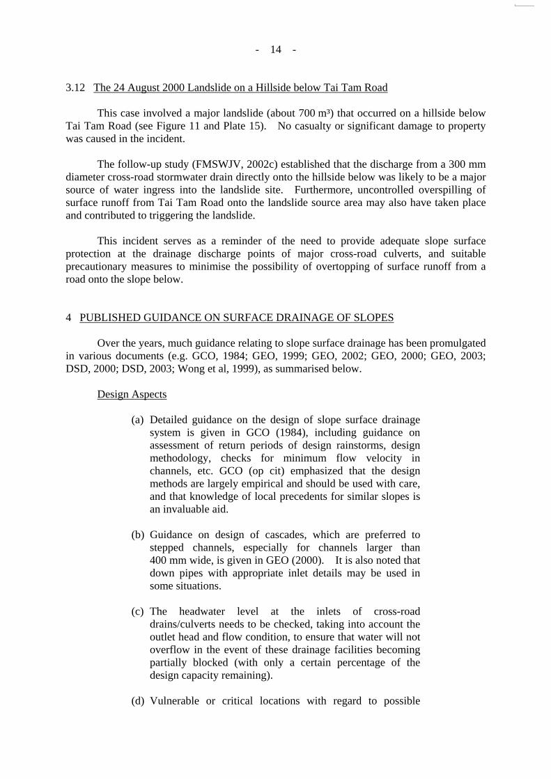
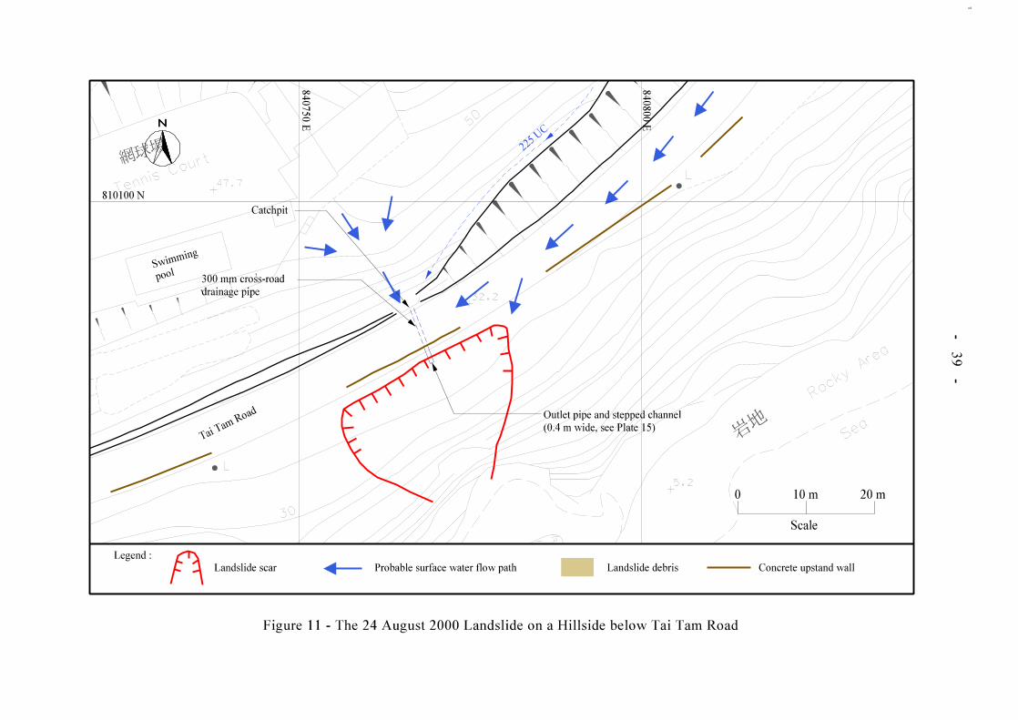
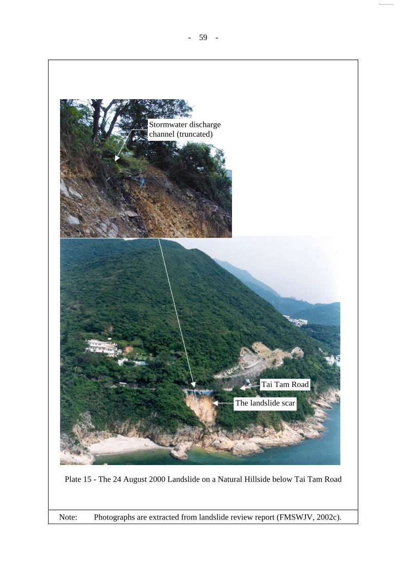
3.12 The 24 August 2000 Landslide on a Hillside below Tai Tam Road
This case involved a major landslide (about 700 m³) that occurred on a hillside below Tai Tam Road (see Figure 11 and Plate 15). No casualty or significant damage to property was caused in the incident.
The follow-up study (FMSWJV, 2002c) established that the discharge from a 300 mm
diameter cross-road stormwater drain directly onto the hillside below was likely to be a major source of water ingress into the landslide site. Furthermore, uncontrolled overspilling of surface runoff from Tai Tam Road onto the landslide source area may also have taken place and contributed to triggering the landslide.
This incident serves as a reminder of the need to provide adequate slope surface
protection at the drainage discharge points of major cross-road culverts, and suitable precautionary measures to minimise the possibility of overtopping of surface runoff from a road onto the slope below.
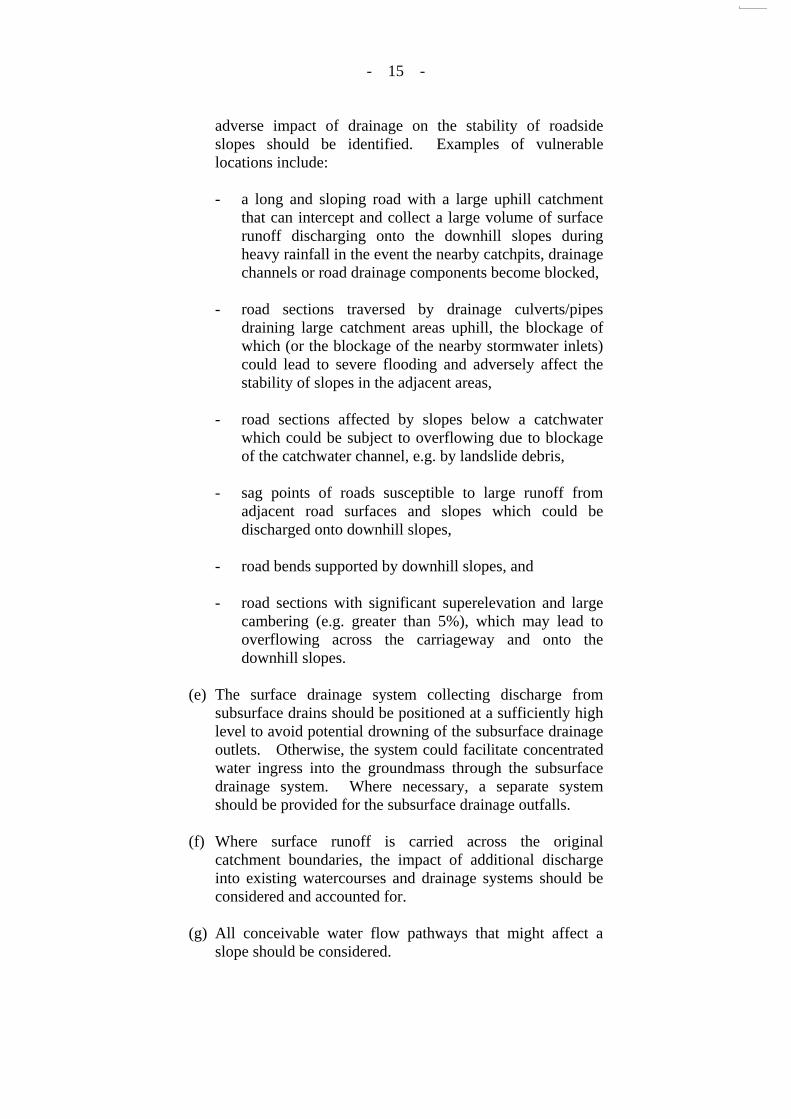
4 PUBLISHED GUIDANCE ON SURFACE DRAINAGE OF SLOPES Over the years, much guidance relating to slope surface drainage has been promulgated
in various documents (e.g. GCO, 1984; GEO, 1999; GEO, 2002; GEO, 2000; GEO, 2003; DSD, 2000; DSD, 2003; Wong et al, 1999), as summarised below.
Design Aspects
(a) Detailed guidance on the design of slope surface drainage system is given in GCO (1984), including guidance on assessment of return periods of design rainstorms, design methodology, checks for minimum flow velocity in channels, etc. GCO (op cit) emphasized that the design methods are largely empirical and should be used with care, and that knowledge of local precedents for similar slopes is an invaluable aid.
(b) Guidance on design of cascades, which are preferred to
stepped channels, especially for channels larger than 400 mm wide, is given in GEO (2000). It is also noted that down pipes with appropriate inlet details may be used in some situations.
(c) The headwater level at the inlets of cross-road
drains/culverts needs to be checked, taking into account the outlet head and flow condition, to ensure that water will not overflow in the event of these drainage facilities becoming partially blocked (with only a certain percentage of the design capacity remaining).
(d) Vulnerable or critical locations with regard to possible
- 15 -
adverse impact of drainage on the stability of roadside slopes should be identified. Examples of vulnerable locations include:
- a long and sloping road with a large uphill catchment
that can intercept and collect a large volume of surface runoff discharging onto the downhill slopes during heavy rainfall in the event the nearby catchpits, drainage channels or road drainage components become blocked,
- road sections traversed by drainage culverts/pipes
draining large catchment areas uphill, the blockage of which (or the blockage of the nearby stormwater inlets) could lead to severe flooding and adversely affect the stability of slopes in the adjacent areas,
- road sections affected by slopes below a catchwater
which could be subject to overflowing due to blockage of the catchwater channel, e.g. by landslide debris,
- sag points of roads susceptible to large runoff from
adjacent road surfaces and slopes which could be discharged onto downhill slopes,
- road bends supported by downhill slopes, and
- road sections with significant superelevation and large
cambering (e.g. greater than 5%), which may lead to overflowing across the carriageway and onto the downhill slopes.
(e) The surface drainage system collecting discharge from
subsurface drains should be positioned at a sufficiently high level to avoid potential drowning of the subsurface drainage outlets. Otherwise, the system could facilitate concentrated water ingress into the groundmass through the subsurface drainage system. Where necessary, a separate system should be provided for the subsurface drainage outfalls.
(f) Where surface runoff is carried across the original
catchment boundaries, the impact of additional discharge into existing watercourses and drainage systems should be considered and accounted for.
(g) All conceivable water flow pathways that might affect a
slope should be considered.
- 16 -
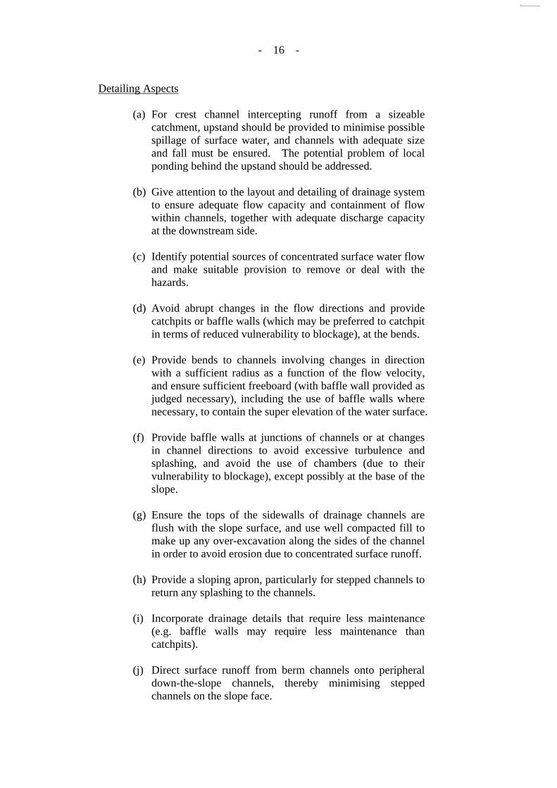
Detailing Aspects
(a) For crest channel intercepting runoff from a sizeable catchment, upstand should be provided to minimise possible spillage of surface water, and channels with adequate size and fall must be ensured. The potential problem of local ponding behind the upstand should be addressed.
(b) Give attention to the layout and detailing of drainage system
to ensure adequate flow capacity and containment of flow within channels, together with adequate discharge capacity at the downstream side.
(c) Identify potential sources of concentrated surface water flow
and make suitable provision to remove or deal with the hazards.
(d) Avoid abrupt changes in the flow directions and provide
catchpits or baffle walls (which may be preferred to catchpit in terms of reduced vulnerability to blockage), at the bends.
(e) Provide bends to channels involving changes in direction
with a sufficient radius as a function of the flow velocity, and ensure sufficient freeboard (with baffle wall provided as judged necessary), including the use of baffle walls where necessary, to contain the super elevation of the water surface.
(f) Provide baffle walls at junctions of channels or at changes
in channel directions to avoid excessive turbulence and splashing, and avoid the use of chambers (due to their vulnerability to blockage), except possibly at the base of the slope.
(g) Ensure the tops of the sidewalls of drainage channels are
flush with the slope surface, and use well compacted fill to make up any over-excavation along the sides of the channel in order to avoid erosion due to concentrated surface runoff.
(h) Provide a sloping apron, particularly for stepped channels to
return any splashing to the channels.
(i) Incorporate drainage details that require less maintenance (e.g. baffle walls may require less maintenance than catchpits).
(j) Direct surface runoff from berm channels onto peripheral
down-the-slope channels, thereby minimising stepped channels on the slope face.
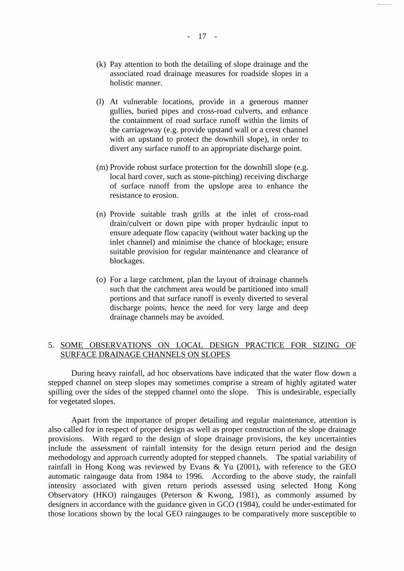
- 17 -
(k) Pay attention to both the detailing of slope drainage and the associated road drainage measures for roadside slopes in a holistic manner.
(l) At vulnerable locations, provide in a generous manner
gullies, buried pipes and cross-road culverts, and enhance the containment of road surface runoff within the limits of the carriageway (e.g. provide upstand wall or a crest channel with an upstand to protect the downhill slope), in order to divert any surface runoff to an appropriate discharge point.
(m) Provide robust surface protection for the downhill slope (e.g.
local hard cover, such as stone-pitching) receiving discharge of surface runoff from the upslope area to enhance the resistance to erosion.
(n) Provide suitable trash grills at the inlet of cross-road
drain/culvert or down pipe with proper hydraulic input to ensure adequate flow capacity (without water backing up the inlet channel) and minimise the chance of blockage; ensure suitable provision for regular maintenance and clearance of blockages.
(o) For a large catchment, plan the layout of drainage channels
such that the catchment area would be partitioned into small portions and that surface runoff is evenly diverted to several discharge points, hence the need for very large and deep drainage channels may be avoided.
5. SOME OBSERVATIONS ON LOCAL DESIGN PRACTICE FOR SIZING OF SURFACE DRAINAGE CHANNELS ON SLOPES
During heavy rainfall, ad hoc observations have indicated that the water flow down a
stepped channel on steep slopes may sometimes comprise a stream of highly agitated water spilling over the sides of the stepped channel onto the slope. This is undesirable, especially for vegetated slopes.
Apart from the importance of proper detailing and regular maintenance, attention is
also called for in respect of proper design as well as proper construction of the slope drainage provisions. With regard to the design of slope drainage provisions, the key uncertainties include the assessment of rainfall intensity for the design return period and the design methodology and approach currently adopted for stepped channels. The spatial variability of rainfall in Hong Kong was reviewed by Evans & Yu (2001), with reference to the GEO automatic raingauge data from 1984 to 1996. According to the above study, the rainfall intensity associated with given return periods assessed using selected Hong Kong Observatory (HKO) raingauges (Peterson & Kwong, 1981), as commonly assumed by designers in accordance with the guidance given in GCO (1984), could be under-estimated for those locations shown by the local GEO raingauges to be comparatively more susceptible to

- 18 -
the occurrence of severe rainstorms. For example, for a time of concentration of, say, 5 minutes, the design rainfall intensity can be under-estimated by some 50% if the approach given in GCO (1984) were to be used for certain areas (Evans & Yu, 2001).
It is noteworthy that GCO (1984) cautioned against the common assumption that the
curves reported by Peterson & Kwong (1981) were representative of the whole of Hong Kong and stated that reference should be made to data from local raingauges for the site under consideration. In light of the above, it would appear prudent for designers to err on the conservative side by adopting the higher rainfall intensity based on reference to both the HKO raingauge data and that of the local raingauges as analysed by Evans & Yu (2001).
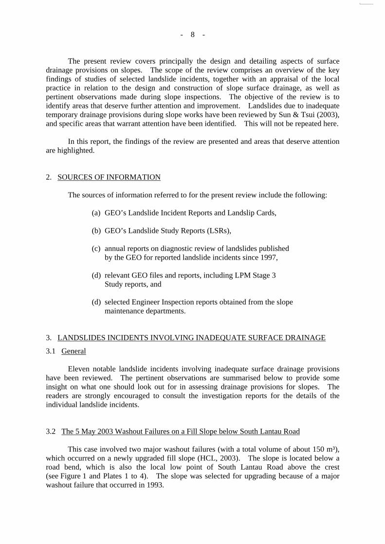
The design methodology of stepped channels is currently under review by the
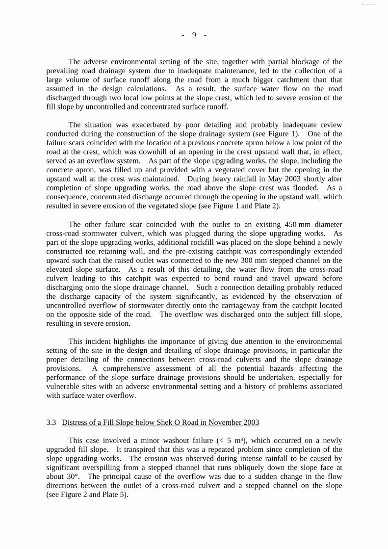
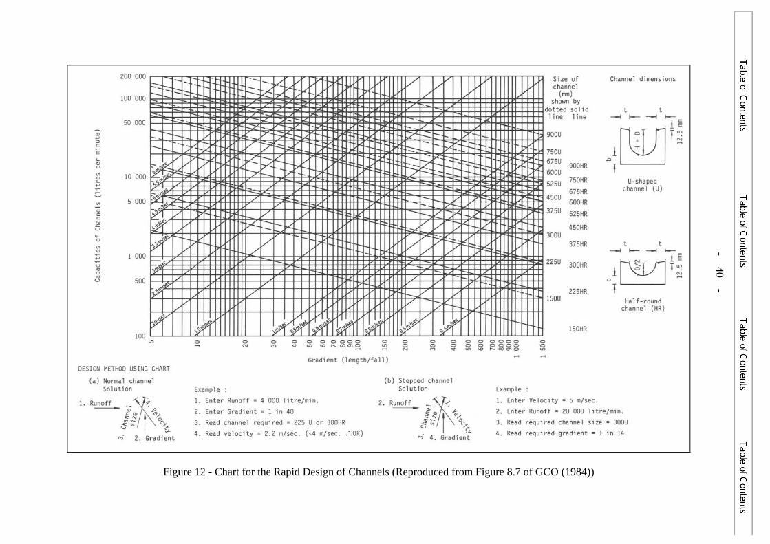
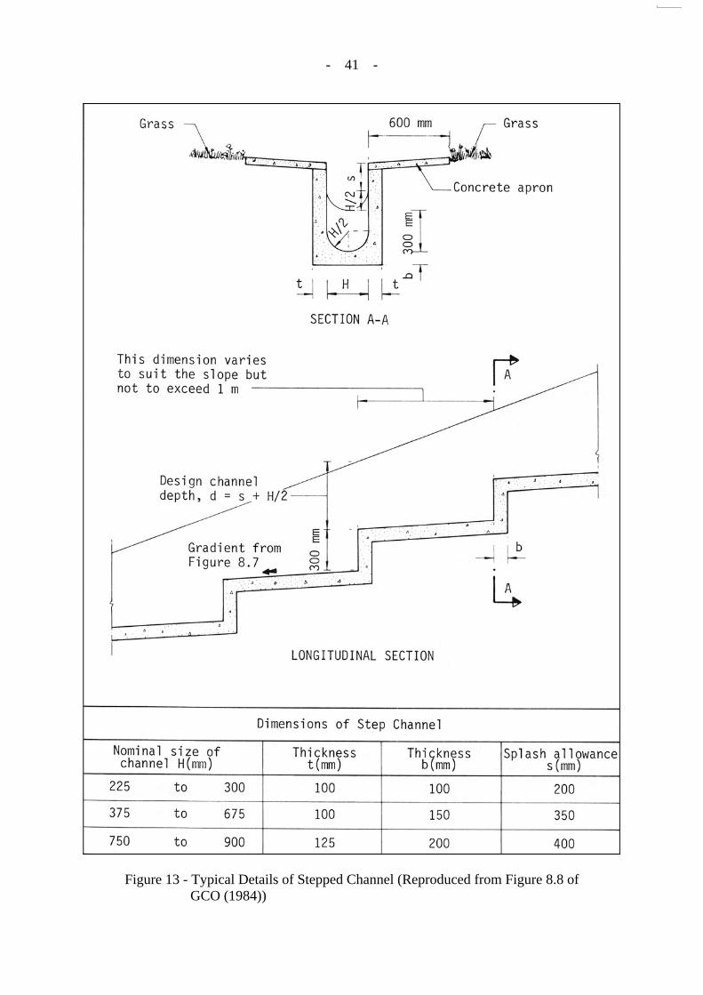
Standards and Testing Division of the GEO. A noteworthy aspect concerns the interpretation of the design charts given in Figures 8.7 and 8.8 of GCO (1984), which are reproduced as Figures 12 and 13 respectively. In the sizing of a stepped channel, the example given in Figure 8.7 of GCO (1984) notes that a stepped channel should be taken as an U-channel in using the design chart. However, there is a grey area when reference is made to Figure 8.8 of GCO (1984) in establishing the corresponding design channel depth, as this is to be based on the assumption of a half-round channel instead of an U-channel.
Reference to the two corresponding figures in the First Edition of the Geotechnical
Manual for Slopes (GCO, 1979) indicates a discrepancy at that time between the cross section (which suggests a design channel depth of (H/2 + s) as per a half-round channel, where H is the nominal size of the channel and s is the splash allowance), and the longitudinal section (which suggests a design channel depth of (H + s), as per an U-channel). This discrepancy was removed in GCO (1984), which suggested a design channel depth corresponding to (H/2 + s) for a half-round channel, instead of (H + s) as per an U-channel. Given the way the previous minor discrepancy was rectified, the outcome is a smaller design channel depth and a consequential inconsistency between Figures 8.7 and 8.8 in GCO (1984), which assume an U-channel and a half-round channel respectively.
The ramification of the above is illustrated by way of a simple example in the
following. For a required channel capacity of 20,000 litres per minute and a design flow velocity of 5 m/sec, a 300 mm U-channel, with a gradient of 1 in 14, is needed in accordance with Figure 12. By reference to Figure 13, the corresponding design channel depth would be 350 mm (incorporating a splash allowance of 200 mm and an effective depth of the channel section corresponding to a half-round channel, instead of an U-channel pursuant to Section A-A in Figure 13). If the effective depth of the channel section were instead taken to correspond to an U-channel in Figure 13, then the design channel depth would become 500 mm. On the other hand, if a consistent assumption were to be made that the two corresponding design charts are to be used for half-round channels, then with the above example, the required channel size would become 450 mm, with a design channel depth of 575 mm (incorporating, in this case, a splash allowance of 350 mm). Thus, making consistent assumptions in the use of the design methodology in GCO (1984) would result in a larger-sized stepped channel as compared with that based on the current recommended methodology.
Some practitioners are of the view that the design of stepped channels using the
approach as recommended in GCO (1984) only provided a starting point, and as such, a larger

- 19 -
channel should always be provided based on judgement and experience of actual performance of stepped channels. A preliminary review by Lam & Siu (2004) also points to the fact that the design methodology given in GCO (1984) may be on the unconservative side. It is noteworthy that some practitioners consider the issue of whether the present design approach for stepped channels is unsatisfactory or not remains a matter of intuition, based on the premise that there is no obvious evidence of problems arising from the use of the current design approach.
As part of the present review, a total of 45 LPM Stage 3 Study reports completed in the
period of 1997 to 2004 were examined in order to get a feel for the approach adopted by different practitioners in respect of the design and detailing of surface drainage provisions. The salient observations of this exercise are summarized in Table 1. Of the above batch of reports, 20 reports covering the period of 2001 to 2004 were further assessed to specifically review the approach adopted in the sizing of stepped channels. The review of these 20 design reports revealed that the methodology recommended in GCO (1984) was adopted by all the designers, and that the sizing of the stepped channels was based entirely on the outcome of the design assessment using Figures 8.7 and 8.8 of GCO (1984), without any further increase in the design channel depth, by the vast majority of the designers (19 out of 20). For the other case, the designer opted to adopt a slightly larger stepped channel than that based on the use of the recommended design charts.
The sample size of the above review is not large. Nevertheless, it highlights the fact
that some practitioners tend to favour strict adherence to the design methodology recommended in GCO (1984) for sizing stepped channels. There are indications that it may not be common practice for designers to opt, based on experience and judgement, to further increase the size of stepped channels beyond that of the recommended methodology, to cater for uncertainties.
Irrespective of the design approach that may be adopted, it would seem prudent to
make some allowance in the final sizing of stepped channels, and drainage provisions in general, for potential partial blockage of channels, particularly for vegetated slopes, given the empirical nature of the recommended design methodology and the simplifying assumptions made. As a related example, GEO (2000a) suggested that a 50% reduction in the design capacity should be assumed for roadside slope drainage provisions. Overall, it would seem advisable for designers to take due cognisance of the relevant site-specific environmental factors in making a considered assessment of the necessary allowance in the design to be made for partial blockage of drainage channels, which may cover the slope drainage provisions as well as the uphill drainage provisions where deemed appropriate, in order to enhance the redundancy and robustness of the overall land drainage system.
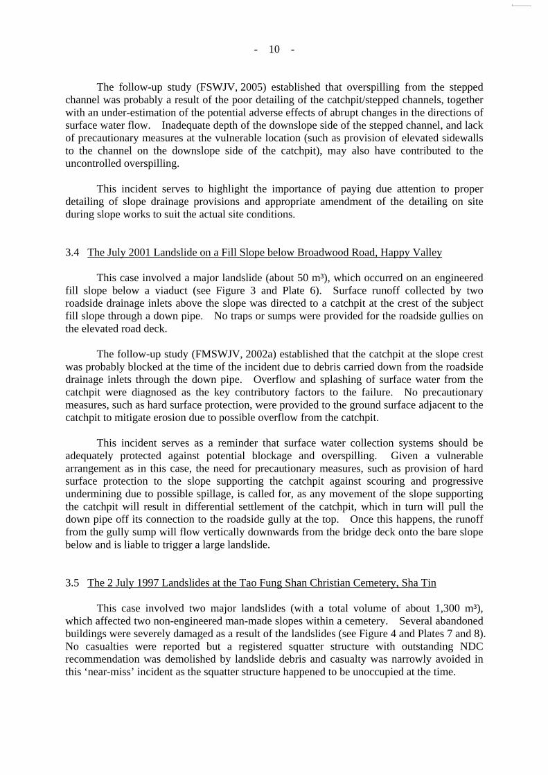
6. EXAMPLES OF INADEQUATE SLOPE SURFACE DRAINAGE PROVISIONS AS OBSERVED IN PRACTICE
Observations have been made of the detailing of slope drainage provisions in landslide
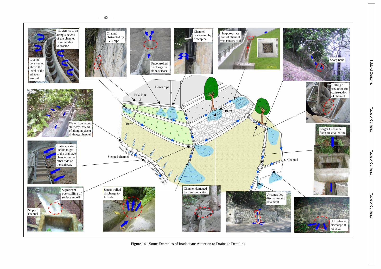
inspections, slope maintenance inspections as well as site visits made during heavy rainstorms. These field inspections have highlighted some examples of inadequate detailing or construction of surface drainage provisions, notwithstanding the extensive guidance given in various publications. Some of these examples (see also Figure 14) include the following:

- 20 -
(a) presence of sharp bends in drainage channels with no catchpits or baffle walls provided to control potential splashing,
(b) inadequate capacity of downstream drainage provisions to
cater for the discharge from the slope (e.g. large channels discharging into smaller-sized channels), hence resulting in overflow,
(c) drainage channels with an as-built fall in a direction that is
opposite to the design intent,
(d) presence of obstructions in drainage channels leading to reduction in drainage capacity,
(e) inadequate construction of drainage channels with the tops
of the sidewalls being above the adjacent ground level (possibly due to over-excavation of the channel width, under-excavation of the channel depth, use of formworks to minimise concrete wastage and subsequent use of soil fill to make up the surrounding ground), hence lead to erosion along the side of the channel,
(f) lack of upstands at the downhill side of road/pavement to
minimise the chance of uncontrolled discharge of surface runoff to the downhill slope at low points or vulnerable locations,
(g) lack of intersecting drains along a long sloping
road/pavement, which may act as a conduit, to reduce accumulated discharge at certain points down the road/pavement and avoid surface erosion or flooding,
(h) drainage channels constructed close to mature trees
necessitating removal of some tree roots, with the attendant risk of causing adverse impact on the tree health condition as well as possible damage to the channels by tree root action in due course,
(i) trees planted too close to drainage channels, hence a risk of
causing damage to the channels due to tree root growth,
(j) undersized drainage channels that can lead to splashing, hence erosion of the vegetated slope surface alongside the drainage channels,
(k) absence of trash grill or debris/silt traps at inlets to main
culverts/drainage channels, making them vulnerable to blockage, especially where the site setting involves major
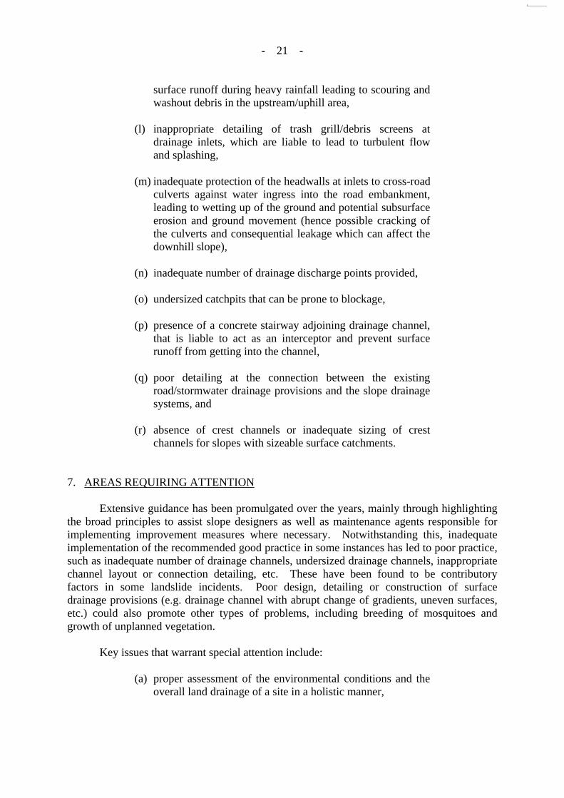
- 21 -
surface runoff during heavy rainfall leading to scouring and washout debris in the upstream/uphill area,
(l) inappropriate detailing of trash grill/debris screens at
drainage inlets, which are liable to lead to turbulent flow and splashing,
(m) inadequate protection of the headwalls at inlets to cross-road
culverts against water ingress into the road embankment, leading to wetting up of the ground and potential subsurface erosion and ground movement (hence possible cracking of the culverts and consequential leakage which can affect the downhill slope),
(n) inadequate number of drainage discharge points provided,
(o) undersized catchpits that can be prone to blockage,
(p) presence of a concrete stairway adjoining drainage channel,
that is liable to act as an interceptor and prevent surface runoff from getting into the channel,
(q) poor detailing at the connection between the existing
road/stormwater drainage provisions and the slope drainage systems, and
(r) absence of crest channels or inadequate sizing of crest
channels for slopes with sizeable surface catchments.
7. AREAS REQUIRING ATTENTION
Extensive guidance has been promulgated over the years, mainly through highlighting the broad principles to assist slope designers as well as maintenance agents responsible for implementing improvement measures where necessary. Notwithstanding this, inadequate implementation of the recommended good practice in some instances has led to poor practice, such as inadequate number of drainage channels, undersized drainage channels, inappropriate channel layout or connection detailing, etc. These have been found to be contributory factors in some landslide incidents. Poor design, detailing or construction of surface drainage provisions (e.g. drainage channel with abrupt change of gradients, uneven surfaces, etc.) could also promote other types of problems, including breeding of mosquitoes and growth of unplanned vegetation.
Key issues that warrant special attention include:
(a) proper assessment of the environmental conditions and the overall land drainage of a site in a holistic manner,
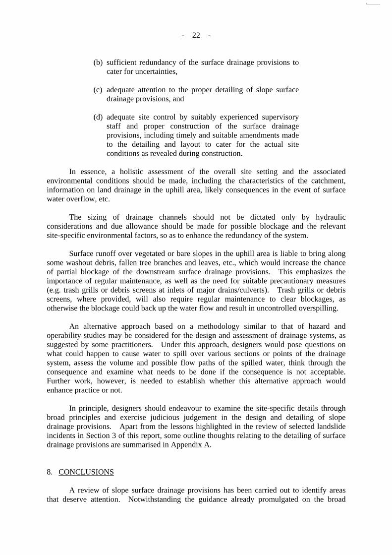
- 22 -
(b) sufficient redundancy of the surface drainage provisions to cater for uncertainties,
(c) adequate attention to the proper detailing of slope surface
drainage provisions, and
(d) adequate site control by suitably experienced supervisory staff and proper construction of the surface drainage provisions, including timely and suitable amendments made to the detailing and layout to cater for the actual site conditions as revealed during construction.
In essence, a holistic assessment of the overall site setting and the associated
environmental conditions should be made, including the characteristics of the catchment, information on land drainage in the uphill area, likely consequences in the event of surface water overflow, etc.
The sizing of drainage channels should not be dictated only by hydraulic
considerations and due allowance should be made for possible blockage and the relevant site-specific environmental factors, so as to enhance the redundancy of the system.
Surface runoff over vegetated or bare slopes in the uphill area is liable to bring along
some washout debris, fallen tree branches and leaves, etc., which would increase the chance of partial blockage of the downstream surface drainage provisions. This emphasizes the importance of regular maintenance, as well as the need for suitable precautionary measures (e.g. trash grills or debris screens at inlets of major drains/culverts). Trash grills or debris screens, where provided, will also require regular maintenance to clear blockages, as otherwise the blockage could back up the water flow and result in uncontrolled overspilling.
An alternative approach based on a methodology similar to that of hazard and
operability studies may be considered for the design and assessment of drainage systems, as suggested by some practitioners. Under this approach, designers would pose questions on what could happen to cause water to spill over various sections or points of the drainage system, assess the volume and possible flow paths of the spilled water, think through the consequence and examine what needs to be done if the consequence is not acceptable. Further work, however, is needed to establish whether this alternative approach would enhance practice or not.
In principle, designers should endeavour to examine the site-specific details through
broad principles and exercise judicious judgement in the design and detailing of slope drainage provisions. Apart from the lessons highlighted in the review of selected landslide incidents in Section 3 of this report, some outline thoughts relating to the detailing of surface drainage provisions are summarised in Appendix A.
8. CONCLUSIONS
A review of slope surface drainage provisions has been carried out to identify areas that deserve attention. Notwithstanding the guidance already promulgated on the broad
- 23 -
principles in relation to surface drainage, inadequate surface drainage provisions have been found to be contributory factors to some of the landslide and washout incidents in practice.
The key issues that warrant attention are highlighted in this report, with a view to
promoting further enhancement of the practice in respect of the design and detailing of surface drainage provisions for slopes.
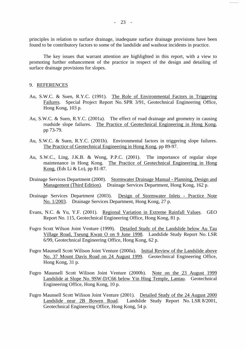
9. REFERENCES Au, S.W.C. & Suen, R.Y.C. (1991). The Role of Environmental Factors in Triggering
Failures. Special Project Report No. SPR 3/91, Geotechnical Engineering Office, Hong Kong, 103 p.
Au, S.W.C. & Suen, R.Y.C. (2001a). The effect of road drainage and geometry in causing roadside slope failures. The Practice of Geotechnical Engineering in Hong Kong, pp 73-79.
Au, S.W.C. & Suen, R.Y.C. (2001b). Environmental factors in triggering slope failures. The Practice of Geotechnical Engineering in Hong Kong, pp 89-97.
Au, S.W.C., Ling, J.K.B. & Wong, P.P.C. (2001). The importance of regular slope maintenance in Hong Kong. The Practice of Geotechnical Engineering in Hong Kong, (Eds Li & Lo), pp 81-87.
Drainage Services Department (2000). Stormwater Drainage Manual - Planning, Design and Management (Third Edition). Drainage Services Department, Hong Kong, 162 p.
Drainage Services Department (2003). Design of Stormwater Inlets - Practice Note No. 1/2003. Drainage Services Department, Hong Kong, 27 p.
Evans, N.C. & Yu, Y.F. (2001). Regional Variation in Extreme Rainfall Values. GEO Report No. 115, Geotechnical Engineering Office, Hong Kong, 81 p.
Fugro Scott Wilson Joint Venture (1999). Detailed Study of the Landslide below Au Tau Village Road, Tseung Kwan O on 9 June 1998. Landslide Study Report No. LSR 6/99, Geotechnical Engineering Office, Hong Kong, 62 p.
Fugro Maunsell Scott Wilison Joint Venture (2000a). Initial Review of the Landslide above No. 37 Mount Davis Road on 24 August 1999. Geotechnical Engineering Office, Hong Kong, 31 p.
Fugro Maunsell Scott Wilison Joint Venture (2000b). Note on the 23 August 1999 Landslide at Slope No. 9SW-D/C66 below Yin Hing Temple, Lantau. Geotechnical Engineering Office, Hong Kong, 10 p.
Fugro Maunsell Scott Wilison Joint Venture (2001). Detailed Study of the 24 August 2000 Landslide near 2B Bowen Road. Landslide Study Report No. LSR 8/2001, Geotechnical Engineering Office, Hong Kong, 54 p.

- 24 -
Fugro Maunsell Scott Wilison Joint Venture (2002a). Review of the July 2001 Landslide on Slope No. 11SE-C/F103 below Broadwood Road, Happy Valley. Geotechnical Engineering Office, Hong Kong, 26 p.
Fugro Maunsell Scott Wilison Joint Venture (2002b). Detailed Study of the 24 August 2000 Landslide below Tai Hang Road, Happy Valley. Landslide Study Report No. LSR 5/2002, Geotechnical Engineering Office, Hong Kong, 48 p.
Fugro Maunsell Scott Wilison Joint Venture (2002c). Review of the 24 August 2000 Landslide at the Hillside below Tai Tam Road. Geotechnical Engineering Office, Hong Kong, 37 p.
Fugro Scott Wilson Joint Venture (1999). Detailed Study of the Landslide below Au Tau Village Road, Tseung Kwan O on 9 June 1998. Landslide Study Report No. LSR 6/99, Geotechnical Engineering Office, Hong Kong, 62 p.
Fugro Scott Wilison Joint Venture (2005). Detailed Study of Distress at Slope No. 15NE-B/FR31 Shek O Road near Lan Nai Wan. Landslide Study Report No. LSR 4/2005, Geotechnical Engineering Office, Hong Kong, 92 p.
Geotechnical Control Office (1979). Geotechnical Manual for Slopes (First Edition). Geotechnical Control Office, Hong Kong, 228 p.
Geotechnical Control Office (1982). Guide to Retaining Wall Design (Geoguide 1) (First Edition). Geotechnical Control Office, Hong Kong, 153 p.
Geotechnical Control Office (1984). Geotechnical Manual for Slopes (Second Edition). Geotechnical Control Office, Hong Kong, 295 p.
Geotechnical Engineering Office (1993). Guide to Retaining Wall Design (Geoguide 1) (Second Edition). Geotechnical Engineering Office, Hong Kong, 267 p.
Geotechnical Engineering Office (1996). Report on the Shum Wan Road Landslide of 13 August 1995. Volume 2: Findings of the Landslide Investigation. Geotechnical Engineering Office, Hong Kong, 51 p.
Geotechnical Engineering Office (1999). Guide to Slope Maintenance (Geoguide 5) (Second Edition). Geotechnical Engineering Office, Hong Kong, 91 p.
Geotechnical Engineering Office (2000). Highway Slope Manual. Geotechnical Engineering Office, Hong Kong, 114 p.
Geotechnical Engineering Office (2002). Guide to Reinforced Fill Structure and Slope Design (Geoguide 6). Geotechnical Engineering Office, Hong Kong, 236 p.
Geotechnical Engineering Office (2003). Guide to Slope Maintenance (Geoguide 5) (Third Edition). Geotechnical Engineering Office, Hong Kong, 132 p.
Geotechnical Engineering Office (2005). Briefing Paper to the Slope Safety Technical Review Board - Natural Terrain Landslide Risk Management and Application of Digital Technology. Geotechnical Engineering Office, 12 p. + 4 Appendices.

- 25 -
Halcrow Asia Partnership Limited (1998a). Detailed Study of the Flooding Incident at Mei Chung Court, Shatin on 2 July 1997. Landslide Study Report No. LSR 6/98, Geotechnical Engineering Office, Hong Kong, 37 p.
Halcrow Asia Partnership Limited (1998b). Detailed Study of the Flooding Incident at Tuen Mun Road, Yau Kom Tau, on 2 and 3 July 1997. Landslide Study Report No. LSR 7/98, Geotechnical Engineering Office, Hong Kong, 40 p.
Halcrow Asia Partnership Limited (1998c). Detailed Study of the Landslides at Tao Fung Shan Christian Cemetery on 2 July 1997. Landslide Study Report No. LSR 2/98, Geotechnical Engineering Office, Hong Kong, 46 p.
Halcrow China Limited (2001). Detailed Study of the 24 August 2000 Landslide on Fill Slope No. 15NE-B/FR123 Below Shek O Road. Landslide Study Report No. LSR 5/2001, Geotechnical Engineering Office, Hong Kong, 73 p.
Halcrow China Limited (2003). Investigation Report on the May 2003 Washout Incident at Slope No. 10SW-C/FR11 on South Lantau Road, Lantau Island. Report submitted to the Geotechnical Engineering Office, Hong Kong, 60 p.
Hui, T.H.H. (2002). Review of the June 2001 Landslides on Slope Nos. 6SE-D/C52, 6SE-B/C4 and 6NE-D/C6 along Route Twisk, Tsuen Wan. Landslide Review Report, Geotechnical Engineering Office, Hong Kong, 38 p.
Lam, J.S. & Siu, C.K. (2004). A Review of Hydraulic Design of Stepped Channels for Slope Drainage. Discussion Note No. DN 1/2004, Geotechnical Engineering Office, Hong Kong, 17 p.
Liu, C.C. (1998). Interim Report on Discharge of Water along Roads at Head of Potentially Unstable Slopes. Technical Note No. TN 3/98, Geotechnical Engineering Office, Hong Kong, 33 p.
Peterson, P. & Kwong, H. (1981). A Design Rain Storm Profile for Hong Kong. Technical Note No. 58, Royal Observatory, Hong Kong, 34 p.
Sun, H.W. & Tsui, H.M. (2003). Review of Notable Landslide Incidents During Slope Works. Landslide Study Report No. LSR 5/2003, Geotechnical Engineering Office, Hong Kong, 147 p.
Wong, H.N., Pang, L.S., Wong, A.C.W., Pun, W.K. & Yu, Y.F. (1999). Application of Prescriptive Measures to Slopes and Retaining Walls (Second Edition). GEO Report No. 56, Geotechnical Engineering Office, Hong Kong, 73 p.

- 26 -
LIST OF TABLES
Table No.
Page No.
1 Summary of Salient Observations from a Review of Slope Drainage Designs in LPM Stage 3 Study Reports
27

- 27 -
Table 1 - Summary of Salient Observations from a Review of Slope Drainage Designs in LPM Stage 3 Study Reports
Observations Yes No
Included detailed drainage design calculations in slope design reports?
43 (96%)
2 (4%)
Checking of self-cleansing velocity of drainage channels? 14 (31%)
31 (69%)
Crest U-channel smaller than 300 mm? 3 (7%)
42 (93%)
Larger-sized channels connected to smaller-sized channels downstream?
1 (2%)
44 (98%)
Provision of trash grills/screens or traps at inlets of discharge points?
7 (16%)
38 (84%)
Specified invert levels of slope drainage runs in design drawings?
0 (0%)
45 (100%)
Sizing of stepped channels based solely on the design methodology given in GCO (1984) without adopting a larger channel to allow for uncertainties (by reference to a sample size of 20 reports)?
19 (95%)
1 (5%)
- 28 -
LIST OF FIGURES
Figure No.
Page No.
1 The 5 May 2003 Washout Failures on an Upgraded Fill Slope below South Lantau Road
29
2 Slope Distress on an Upgraded Fill Slope below Shek O Road near Lan Nai Wan, Shek O
30
3 The July 2001 Landslide on a Fill Slope below Broadwood Road, Happy Valley
31
4 The 2 July 1997 Landslides below Tao Fung Shan Christian Cemetery, Sha Tin
32
5 The 9 June 1998 Landslide on a Fill Slope below Au Tau Village Road, Tseung Kwan O
33
6 The 24 August 2000 Landslide on a Hillside above Bowen Road
34
7 The 24 August 1999 Landslide on a Hillside above Mount Davis Road
35
8 The 23 August 1999 Landslide on an Upgraded Cut Slope below Yin Hing Temple, Lantau
36
9 The June 2001 Landslide on an Upgraded Cut Slope at Route Twisk
37
10 The 24 August 2000 Landslides on Disturbed Terrain below Tai Hang Road
38
11 The 24 August 2000 Landslide on a Hillside below Tai Tam Road
39
12 Chart for the Rapid Design of Channels (Reproduced from Figure 8.7 of GCO (1984))
40
13 Typical Details of Stepped Channel (Reproduced from Figure 8.8 of GCO (1984))
41
14 Some Examples of Inadequate Attention to Drainage Detailing
42

- 31 -
Figure 3 - The July 2001 Landslide on a Fill Slope below Broadwood Road, Happy Valley


- 40 -
Figure 12 - Chart for the Rapid Design of Channels (Reproduced from Figure 8.7 of GCO (1984))
- 41 -
Figure 13 - Typical Details of Stepped Channel (Reproduced from Figure 8.8 of
GCO (1984))
- 42 -
Figure 14 - Some Examples of Inadequate Attention to Drainage Detailing
Backfill material along sidewall of the channel is vulnerable to erosion
Channel damaged by tree root action
Uncontrolled discharge at toe area
Channel obstructed by downpipe
Sharp bend
Uncontrolled discharge to hillside
PVC Pipe
Down pipe
Stepped channel U-Channel
Uncontrolled discharge on slope surface
Berm Water flow along stairway instead of along adjacent drainage channel
Channel constructed above the level of the adjacent ground
Berm
Surface water unable to get to the drainage channel on the other side of the stairway
Stepped channel
Significant over spilling of surface runoff
Cutting of tree roots for construction of channel
Larger U-channel feeds to smaller one
Inappropriate fall of channel
was constructed
Uncontrolled discharge onto pavement
Channel obstructed by PVC pipe
- 43 -
LIST OF PLATES
Plate No.
Page No.
1 The 5 May 2003 Washout Failures on a Fill Slope below South Lantau Road
45
2 Surface Drainage System Before and After the Slope Upgrading Works at Scar A of the 5 May 2003 Washout Failures below South Lantau Road
46
3 The Catchpit at the Crest of Scar B of the 5 May 2003 Washouts at South Lantau Road
47
4 The Energy Disperser for a 1350 mm Diameter Pipe Culvert and Erosion during the 5 May 2003 Washouts at South Lantau Road
48
5 Slope Distress and Erosion on a Fill Slope below Shek O Road near Lan Nai Wan, Shek O
49
6 The July 2001 Landslide on a Fill Slope below Broadwood Road, Happy Valley
50
7 The 2 July 1997 Landslide A on a Cut Slope at Tao Fung Shan Christian Cemetery, Sha Tin
51
8 The 2 July 1997 Landslide B on a Cut Slope at Tao Fung Shan Christian Cemetery, Sha Tin
52
9 The 9 June 1998 Landslide on a Fill Slope below Au Tau Village Road, Tseung Kwan O
53
10 The 24 August 2000 Landslide on a Natural Hillside above Bowen Road
54
11 The 24 August 1999 Landslide on a Natural Hillside above Mount Davis Road
55
12 The 23 August 1999 Landslide on a Cut Slope below Yin Hing Temple, Lantau
56
13 The June 2001 Landslide on a Cut Slope at Route Twisk
57
14 The 24 August 2000 Landslides on a Disturbed Hillside below Tai Hang Road
58

- 44 -
Plate No.
Page No.
15 The 24 August 2000 Landslide on a Natural Hillside below Tai Tam Road
59

- 45 -
Plate 1 - The 5 May 2003 Washout Failures on a Fill Slope below South Lantau Road
Note: Photographs are extracted from HCL (2003) investigation report.
Flooding along South Lantau Road on 5 May 2003
Scar B
Scar A
- 46 -
Plate 2 - Surface Drainage System Before and After the Slope Upgrading Works at
Scar A of the 5 May 2003 Washout Failures below South Lantau Road
Note: Photographs are extracted from HCL (2003) investigation report.
Rigid surface near thecrest of the slope divertedthe runoff into the steppedchannel (see Figure 1)
Before slope upgrading works
After slope upgrading works
12 m gap withoutupstand wall/earthbund at slope crest
- 47 -
Plate 3 - The Catchpit at the Crest of Scar B of the 5 May 2003 Washouts at
South Lantau Road
Note: Photographs are extracted from HCL (2003) investigation report.
Original outlet of the catchpit for a 450 mm diameter cross-road drain, which was plugged and burst during the washout failure (see Figure 1)

- 48 -
Plate 4 - The Energy Disperser for a 1350 mm Diameter Pipe Culvert and Erosion during
the 5 May 2003 Washouts at South Lantau Road
Note: Photographs are extracted from HCL (2003) investigation report.
Energy disperser - Grade 200 rockfill
1350 diameter pipe culvert Before failure
After failure
- 49 -
Plate 5 - Slope Distress and Erosion on a Fill Slope below Shek O Road near
Lan Nai Wan, Shek O
Note: Photographs are extracted from report No. LSR 4/2005 (FSWJV, 2005).
Stepped channel
Surface runoff overtopping from the stepped channel
Erosion scar
- 50 -
Plate 6 - The July 2001 Landslide on a Fill Slope below Broadwood Road, Happy Valley
Note: Photographs are extracted from landslide review report (FMSWJV, 2002a).
The 2001 landslide site
- 51 -
Plate 7 - The 2 July 1997 Landslide A on a Cut Slope at Tao Fung Shan Christian
Cemetery, Sha Tin
Note: Photographs are extracted from report No. LSR 2/98 (HAP, 1998c).
- 52 -
Note: Photographs are extracted from report No. LSR 2/98 (HAP, 1998c).
Retaining wall without proper drainage system
Plate 8 - The 2 July 1997 Landslide B on a Cut Slope at Tao Fung Shan Christian Cemetery, Sha Tin
- 53 -
Plate 9 - The 9 June 1998 Landslide on a Fill Slope below Au Tau Village Road, Tseung Kwan O
Note: Photographs are extracted from report No. LSR 6/99 (FSWJV, 1999).
Surface water flow towards landslide scar
Surface water flow along road
Overflow from streamcourse
- 54 -
Plate 10 - The 24 August 2000 Landslide on a Natural Hillside above Bowen Road
Note: Photographs are extracted from report No. LSR 8/2001 (FMSWJV, 2001).
Old topsoil
Crest channel
Landslide scar
Crest channel
Landslide scar
Shotcrete cover
Channel in landslide scar
- 55 -
Plate 11 - The 24 August 1999 Landslide on a Natural Hillside above Mount Davis Road
Note: Photographs are extracted from landslide review report (FMSWJV, 2000a).
Blocked catchpit
The landslide site
- 56 -
Plate 12 - The 23 August 1999 Landslide on a Cut Slope below Yin Hing Temple, Lantau
Note: Photographs are extracted from summary note (FMSWJV, 2000b).
Blocked catchpit 50 m from landslide
The blocked catchpit located at the toe of slope no. 9SW-D/CR43

- 57 -
Plate 13 - The June 2001 Landslide on a Cut Slope at Route Twisk
Note: Photographs are extracted from landslide review report (Hui, 2002).
Local depression at the berm withoutU-channel (approximate 3 m wide)

- 58 -
Plate 14 - The 24 August 2000 Landslide on a Disturbed Hillside below Tai Hang Road
Note: Photographs are extracted from report No. LSR 5/2002 (FMSWJV, 2002b).
Pedestrian pavement at about same level as road surface
Blocked catchpit
Landslide scars
Tai Hang Road
- 59 -
Plate 15 - The 24 August 2000 Landslide on a Natural Hillside below Tai Tam Road
Note: Photographs are extracted from landslide review report (FMSWJV, 2002c).
The landslide scar
Tai Tam Road
Stormwater discharge channel (truncated)

- 60 -
APPENDIX A
ITEMS FOR ATTENTION IN RESPECT OF DETAILING OF SURFACE DRAINAGE PROVISIONS

- 61 -
CONTENTS
Page No. Cover Page 60 CONTENTS 61 A1. ITEMS FOR ATTENTION IN RESPECT OF DETAILING OF 62 SURFACE DRAINAGE PROVISIONS LIST OF FIGURES 64
- 62 -
A1. ITEMS FOR ATTENTION IN RESPECT OF DETAILING OF SURFACE DRAINAGE PROVISIONS
(a) Provide drainage measures with minimal maintenance
requirements (e.g. half-round channels grading to U-channels along berms in existing slopes to achieve a steeper gradient and hence promote self-cleansing).
(b) Avoid offset between the alignments of inlet and outlet
channels in a catchpit to minimise turbulence and overspilling. Provide ‘oversized’ catchpits to enhance redundancy, and rotate the downstream sidewall of catchpit to be normal to the direction of the downstream channel to minimise splashing. Where appropriate, provide elevated sidewalls to the downstream channel below the catchpit to minimise splashing.
(c) Consider conveying anticipated heavy discharge at slope
crest (e.g. major stream course) directly to slope toe, instead of directing the discharge to peripheral drains with the attendant risk of overspilling.
(d) Consider the use of intermediate channels (e.g. chevron
drains) to intercept surface runoff from large catchments.
(e) Consider providing drainage channel along locations of sharp changes in slope gradients (e.g. soil/rock interface).
(f) Consider providing short relief pipes below the treads of
stepped channels to intercept shallow subsurface flow, with due regard to buildability issues.
(g) Provide adequate movement joints for channels that are
liable to be subject to post-construction differential movement (e.g. across a site with recompacted fill overlying untreated old fill in a valley setting).
(h) Consider providing deep catchpits at slope toe to act as a
temporary buffer zone to cater for excessive flows during intense rainfall, with due regard to buildability issues and adequate access for regular maintenance.
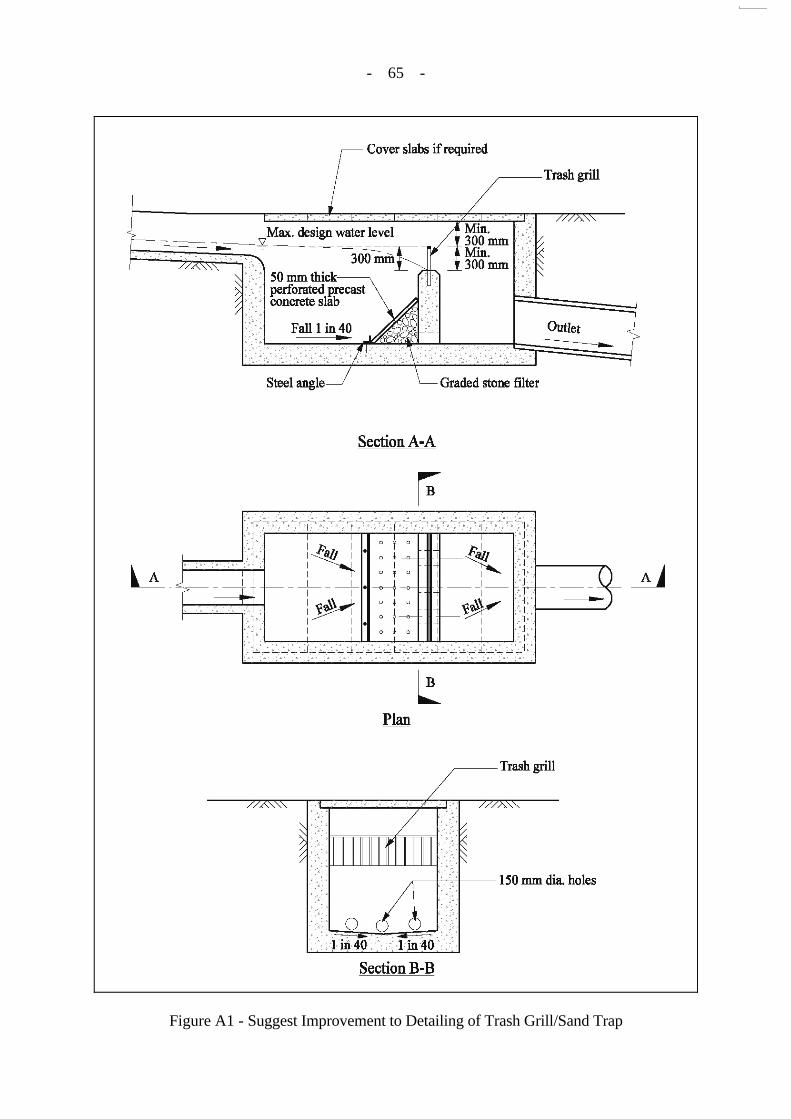
(i) Consider the adoption of an improved trash grill/sand trap
detailing as shown in Figure A1.
(j) Adjust the drainage layout and detailing during construction as appropriate to take account of the actual site conditions.

- 63 -
(k) Consider the specification of invert levels for slope drainage runs to facilitate proper construction of drainage channels.
(l) Explore alternative detailing to stepped channels to reduce
the flow velocity down a channel in a more effective manner, as the runoff could by-pass the steps under fast flowing conditions (i.e. ‘skimming’ flow regime).

- 64 -
LIST OF FIGURES
Figure No.
Page No.
A1 Suggest Improvement to Detailing of Trash Grill/Sand Trap
65
- 65 -
Figure A1 - Suggest Improvement to Detailing of Trash Grill/Sand Trap


GEO PUBLICATIONS AND ORDERING INFORMATION ㈯力工程處刊物及訂購㈾料
A selected list of major GEO publications is given in the next page. An up-to-date full list of GEO publications can be found at the CEDD Website http://www.cedd.gov.hk on the Internet under “Publications”. Abstracts for the documents can also be found at the same website. Technical Guidance Notes are published on the CEDD Website from time to time to provide updates to GEO publications prior to their next revision.
部份土力工程處的主要刊物目錄刊載於下頁。而詳盡及最新的
土力工程處刊物目錄,則登載於土木工程拓展署的互聯網網頁
http://www.cedd.gov.hk 的“刊物”版面之內。刊物的摘要及更新
刊物內容的工程技術指引,亦可在這個網址找到。
Copies of GEO publications (except maps and other publications which are free of charge) can be purchased either by:
讀者可採用以下方法購買土力工程處刊物(地質圖及免費刊物
除外):
writing to Publications Sales Section, Information Services Department, Room 402, 4th Floor, Murray Building, Garden Road, Central, Hong Kong. Fax: (852) 2598 7482
書面訂購
香港中環花園道
美利大廈4樓402室
政府新聞處
刊物銷售組
傳真: (852) 2598 7482
or 或 − Calling the Publications Sales Section of Information Services
Department (ISD) at (852) 2537 1910 − Visiting the online Government Bookstore at
http://bookstore.esdlife.com − Downloading the order form from the ISD website at
http://www.isd.gov.hk and submit the order online or by fax to (852) 2523 7195
− Placing order with ISD by e-mail at [email protected]
− 致電政府新聞處刊物銷售小組訂購 (電話:(852) 2537 1910)
− 進入網上「政府書店」選購,網址為 http://bookstore.esdlife.com
− 透過政府新聞處的網站 (http://www.isd.gov.hk) 於網上遞
交訂購表格,或將表格傳真至刊物銷售小組 (傳真:(852)
2523 7195)
− 以電郵方式訂購 (電郵地址:[email protected])
1:100 000, 1:20 000 and 1:5 000 maps can be purchased from:
讀者可於下列地點購買1:100 000,1:20 000及1:5 000地質圖:
Map Publications Centre/HK, Survey & Mapping Office, Lands Department, 23th Floor, North Point Government Offices, 333 Java Road, North Point, Hong Kong. Tel: 2231 3187 Fax: (852) 2116 0774
香港北角渣華道333號
北角政府合署23樓
地政總署測繪處
電話: 2231 3187
傳真: (852) 2116 0774
Requests for copies of Geological Survey Sheet Reports, publications and maps which are free of charge should be sent to:
如欲索取地質調查報告、其他免費刊物及地質圖,請致函:
For Geological Survey Sheet Reports and maps which are free of charge: Chief Geotechnical Engineer/Planning, (Attn: Hong Kong Geological Survey Section) Geotechnical Engineering Office, Civil Engineering and Development Department, Civil Engineering and Development Building, 101 Princess Margaret Road, Homantin, Kowloon, Hong Kong. Tel: (852) 2762 5380 Fax: (852) 2714 0247 E-mail: [email protected]
地質調查報告及地質圖:
香港九龍何文田公主道101號
土木工程拓展署大樓
土木工程拓展署
土力工程處
規劃部總土力工程師
(請交:香港地質調查組)
電話: (852) 2762 5380
傳真: (852) 2714 0247
電子郵件: [email protected]
For other publications which are free of charge: Chief Geotechnical Engineer/Standards and Testing, Geotechnical Engineering Office, Civil Engineering and Development Department, Civil Engineering and Development Building, 101 Princess Margaret Road, Homantin, Kowloon, Hong Kong. Tel: (852) 2762 5346 Fax: (852) 2714 0275 E-mail: [email protected]
其他免費刊物:
香港九龍何文田公主道101號
土木工程拓展署大樓
土木工程拓展署
土力工程處
標準及測試部總土力工程師
電話: (852) 2762 5346
傳真: (852) 2714 0275
電子郵件: [email protected]

MAJOR GEOTECHNICAL ENGINEERING OFFICE PUBLICATIONS 土力工程處之主要刊物
GEOTECHNICAL MANUALS Geotechnical Manual for Slopes, 2nd Edition (1984), 300 p. (English Version), (Reprinted, 2000).
斜坡岩土工程手冊(1998),308頁(1984年英文版的中文譯本)。
Highway Slope Manual (2000), 114 p. GEOGUIDES Geoguide 1 Guide to Retaining Wall Design, 2nd Edition (1993), 258 p. (Reprinted, 2000).
Geoguide 2 Guide to Site Investigation (1987), 359 p. (Reprinted, 2000).
Geoguide 3 Guide to Rock and Soil Descriptions (1988), 186 p. (Reprinted, 2000).
Geoguide 4 Guide to Cavern Engineering (1992), 148 p. (Reprinted, 1998).
Geoguide 5 Guide to Slope Maintenance, 3rd Edition (2003), 132 p. (English Version).
岩土指南第五冊 斜坡維修指南,第三版(2003),120頁(中文版)。
Geoguide 6 Guide to Reinforced Fill Structure and Slope Design (2002), 236 p. GEOSPECS Geospec 1 Model Specification for Prestressed Ground Anchors, 2nd Edition (1989), 164 p. (Reprinted,
1997).
Geospec 3 Model Specification for Soil Testing (2001), 340 p. GEO PUBLICATIONS GCO Publication No. 1/90
Review of Design Methods for Excavations (1990), 187 p. (Reprinted, 2002).
GEO Publication No. 1/93
Review of Granular and Geotextile Filters (1993), 141 p.
GEO Publication No. 1/2000
Technical Guidelines on Landscape Treatment and Bio-engineering for Man-made Slopes and Retaining Walls (2000), 146 p.
GEO Publication No. 1/2006
Foundation Design and Construction (2006), 376 p.
GEOLOGICAL PUBLICATIONS The Quaternary Geology of Hong Kong, by J.A. Fyfe, R. Shaw, S.D.G. Campbell, K.W. Lai & P.A. Kirk (2000),210 p. plus 6 maps.
The Pre-Quaternary Geology of Hong Kong, by R.J. Sewell, S.D.G. Campbell, C.J.N. Fletcher, K.W. Lai & P.A.Kirk (2000), 181 p. plus 4 maps. TECHNICAL GUIDANCE NOTES TGN 1 Technical Guidance Documents