NJ650.1402 Surface Drainage
12
Chapter 2 Surface Drainage Part NJ650.14 Water Management Guide (NJWMG, 07/2007) NJ2- 1 NJ650.1402 Surface Drainage a) General Surface drainage is the orderly removal of excess water from the land surface and the root zone by means of channels or ditches supplemented, if necessary, by shaping and grading of the land surface to provide slope toward the channels. A surface drainage system is designed to remove excess water at a rate which will prevent long periods of standing water or flooding without excessive erosion, so that crops will have adequate moisture conditions for growth. The design capacity of drainage systems depends on several interrelated factors including rainfall patterns, soil characteristics and crops grown. For the northern humid region of the country that includes New Jersey, a series of drainage runoff curves were developed that define the rate at which runoff is to be removed based on the value of the crop or land protected. These curves generally apply to flatland areas, which for New Jersey typically includes land having a grade of one percent or less and where the contributing upland watershed has an average slope of ten percent or less. The drainage runoff curves establish the efficiency at which excess water is removed from the landscape. It is expected that out of bank flooding will occur with the flood waters to be removed in a period of time necessary to avoid crop damage. Runoff Curve D provides fair agricultural drainage and is applied to areas of low value crops, pasture, and woodland where excess water is to be removed within 24 to 48 hours. Runoff Curve C provides good agricultural drainage and is applied to field crop areas where excess water is to be removed within 12 to 24 hours. Runoff Curve B provides for excellent agricultural drainage of high value crops such as vegetables and turf grass where excess water is to be removed in 6 to 12 hours. Runoff Curve A provides for good protection from overflow, but will not eliminate flood runoff. Appendix A contains an exhibit that provides the acres drained per quantity of flow for the four drainage runoff curves. b) Types of channels Field ditches Field ditches are shallow graded channels usually having flat side slopes that collect water in a field and convey the water to a channel. Cross sections are typically “V” or trapezoidal and may be farmed or vegetated. The steepest side slope for a farmed field ditch is 8H:1V. If not farmed or crossed by equipment, the steepest recommended side slope for a field ditch in a cropped field is 4H:1V and 3H:1V in a pasture. Field ditches may require cleanout following tillage operations. When field ditches are not cropped, weed growth must be controlled by mowing or spraying. Lateral ditches Field ditches convey water to lateral ditches. The lateral receives this water and sometimes water from the filled surface and conveys it to the main ditch. Lateral ditches require periodic maintenance to control vegetation on the bottom and side slopes. Sides slopes of 3H:1V or flatter are recommended for ease of mowing. Where
-
Upload
truongquynh -
Category
Documents
-
view
239 -
download
1
Transcript of NJ650.1402 Surface Drainage

Chapter 2 Surface Drainage Part NJ650.14 Water Management Guide
(NJWMG, 07/2007) NJ2- 1
NJ650.1402 Surface Drainage a) General Surface drainage is the orderly removal of excess water from the land surface and the root zone by means of channels or ditches supplemented, if necessary, by shaping and grading of the land surface to provide slope toward the channels. A surface drainage system is designed to remove excess water at a rate which will prevent long periods of standing water or flooding without excessive erosion, so that crops will have adequate moisture conditions for growth. The design capacity of drainage systems depends on several interrelated factors including rainfall patterns, soil characteristics and crops grown. For the northern humid region of the country that includes New Jersey, a series of drainage runoff curves were developed that define the rate at which runoff is to be removed based on the value of the crop or land protected. These curves generally apply to flatland areas, which for New Jersey typically includes land having a grade of one percent or less and where the contributing upland watershed has an average slope of ten percent or less. The drainage runoff curves establish the efficiency at which excess water is removed from the landscape. It is expected that out of bank flooding will occur with the flood waters to be removed in a period of time necessary to avoid crop damage. Runoff Curve D provides fair agricultural drainage and is applied to areas of low value crops, pasture, and woodland where excess water is to be removed within 24 to 48 hours.
Runoff Curve C provides good agricultural drainage and is applied to field crop areas where excess water is to be removed within 12 to 24 hours. Runoff Curve B provides for excellent agricultural drainage of high value crops such as vegetables and turf grass where excess water is to be removed in 6 to 12 hours. Runoff Curve A provides for good protection from overflow, but will not eliminate flood runoff. Appendix A contains an exhibit that provides the acres drained per quantity of flow for the four drainage runoff curves. b) Types of channels Field ditches
Field ditches are shallow graded channels usually having flat side slopes that collect water in a field and convey the water to a channel. Cross sections are typically “V” or trapezoidal and may be farmed or vegetated. The steepest side slope for a farmed field ditch is 8H:1V. If not farmed or crossed by equipment, the steepest recommended side slope for a field ditch in a cropped field is 4H:1V and 3H:1V in a pasture. Field ditches may require cleanout following tillage operations. When field ditches are not cropped, weed growth must be controlled by mowing or spraying. Lateral ditches Field ditches convey water to lateral ditches. The lateral receives this water and sometimes water from the filled surface and conveys it to the main ditch. Lateral ditches require periodic maintenance to control vegetation on the bottom and side slopes. Sides slopes of 3H:1V or flatter are recommended for ease of mowing. Where

Chapter 2 Surface Drainage Part NJ650.14 Water Management Guide
(NJWMG, 07/2007) NJ2- 2
excessive sediment deposition occurs in a lateral, occasional cleanout will be required. Main ditches The main ditch is the outlet for the drainage system. It receives flow from lateral ditches and sometimes other mains. c) Types of open drain systems
Drains should be located to fit the farm or other land use operations and should have capacity to handle the runoff and not cause harmful erosion. The drain system should cause excess water to flow readily from the
land to the disposal drain. Five common drain systems are described in this section. (1) Random drain system This type system is adapted to drainage systems on undulating land where only scattered wet areas require drainage. The ditches should be located so they intercept depressions and provide the least interfer-ence with farming operations (fig. 2–1). The ditches should be shallow and have side slopes flat enough for farm equipment to cross. Precision land forming and smoothing help to assure the removal of surface water from less permeable soil.
Figure 2–1 Random drains

Chapter 2 Surface Drainage Part NJ650.14 Water Management Guide
(NJWMG, 07/2007) NJ2- 3
(2) Parallel drain system This type system is applicable to land where the topography is flat and regular and where uniform drainage is needed. The ditches are established parallel but not necessarily equidistant, as shown in figure 2–2. The direction of the land slope generally determines the direction of the ditches. Field ditches are generally perpendicular to the slope, and laterals run in the direction of the slope. The location of diversions, cross slope ditches, and access roads for farming equipment can also influence the drain
location. Spacing of the field ditches depends upon the water tolerance of crops, the soil hydraulic conductivity, and the uniformity of the topography. Land forming can reduce the number of ditches required by making the topography more uniform. Where possible, spacing should be adjusted to fit the number of passes of tillage and harvesting equipment.
Figure 2-2 Parallel surface drains

Chapter 2 Surface Drainage Part NJ650.14 Water Management Guide
(NJWMG, 07/2007) NJ2- 4
(3) Cross slope drain system
Figure 2–3 Reconstructing cross slope drain system
Typical V-channel section Side slopes not less than 10:1

Chapter 2 Surface Drainage Part NJ650.14 Water Management Guide
(NJWMG, 07/2007) NJ2- 5
A cross slope drain system is used to drain sloping land, to prevent the accumulation of water from higher land, and to prevent the concentration of water within a field. The field ditches work best on slopes of less than 2 percent. The drain is located across the slope as straight as topography will permit (fig. 2–3). The spacing of these ditches varies with the land slope and should be based on recommendations contained in this guide. The excavated material should be placed in low areas or on the downhill side of the drain. Land forming or smoothing between the ditches improves operation of the system by preventing the concentration of flow and the occurrence of ponding.
(4) Bedding Bedding resembles a system of parallel field ditches with the intervening land shaped to a raised, rounded surface (fig. 2–4). This drainage
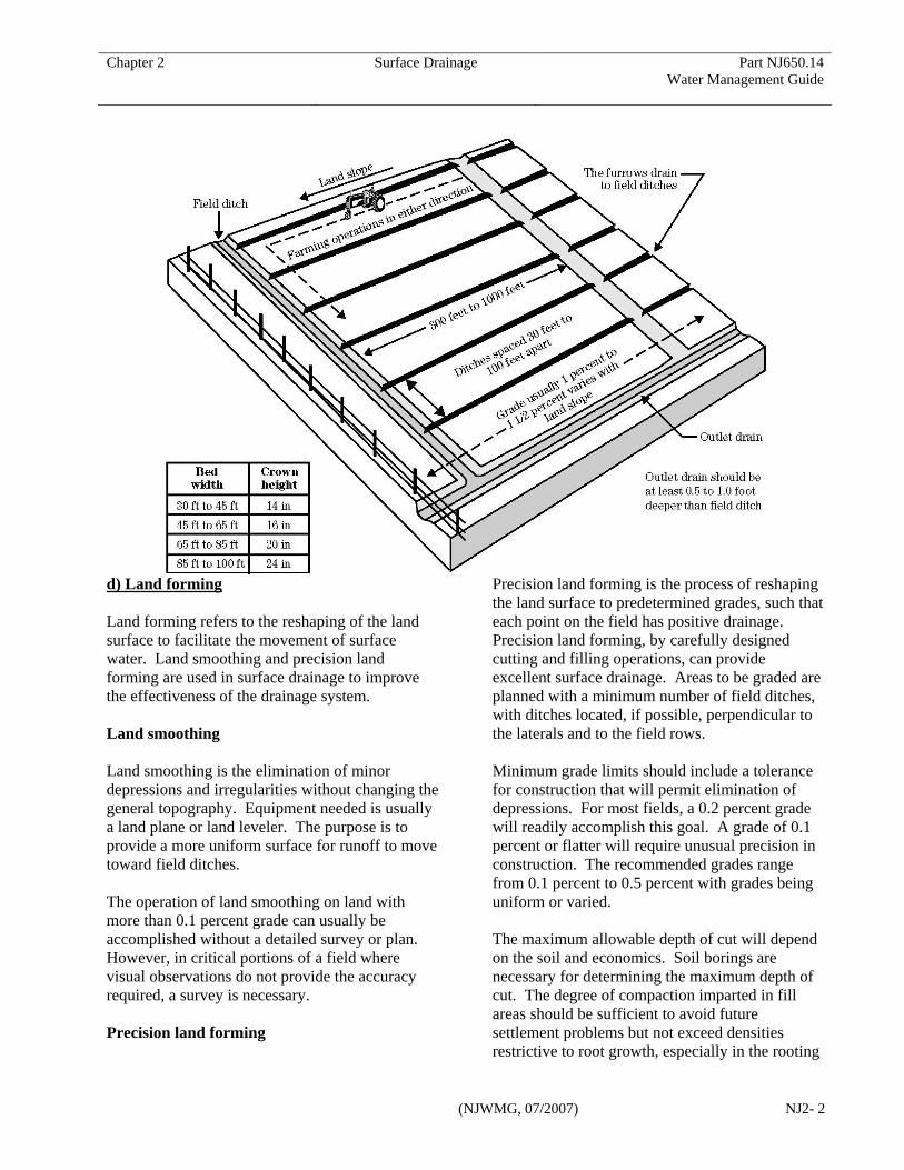
system generally is used where slopes are flat and the soil is slowly permeable and where other types of drainage are not economically feasible. A bedding system generally is in small land areas and is installed using farm equipment. Beds are established to run with the land slope or in the direction of the most desirable outlet. Local information should be used to determine the width of beds, the crown height, construction method, and maintenance.
(5) Narrow raised beds A narrow bed system has a raised bed wide enough for single or double cropping rows to provide an aerated surface profile. This system facilitates surface water movement and aeration of the shallow root zone. When used with plastic covers for weed control, evaporation control, and nutrient management, the narrow bed system can be extremely effective for some cropping systems.
Figure 2–4 Surface drainage bedding
Chapter 2 Surface Drainage Part NJ650.14 Water Management Guide
(NJWMG, 07/2007) NJ2- 2
d) Land forming Land forming refers to the reshaping of the land surface to facilitate the movement of surface water. Land smoothing and precision land forming are used in surface drainage to improve the effectiveness of the drainage system. Land smoothing Land smoothing is the elimination of minor depressions and irregularities without changing the general topography. Equipment needed is usually a land plane or land leveler. The purpose is to provide a more uniform surface for runoff to move toward field ditches. The operation of land smoothing on land with more than 0.1 percent grade can usually be accomplished without a detailed survey or plan. However, in critical portions of a field where visual observations do not provide the accuracy required, a survey is necessary. Precision land forming
Precision land forming is the process of reshaping the land surface to predetermined grades, such that each point on the field has positive drainage. Precision land forming, by carefully designed cutting and filling operations, can provide excellent surface drainage. Areas to be graded are planned with a minimum number of field ditches, with ditches located, if possible, perpendicular to the laterals and to the field rows. Minimum grade limits should include a tolerance for construction that will permit elimination of depressions. For most fields, a 0.2 percent grade will readily accomplish this goal. A grade of 0.1 percent or flatter will require unusual precision in construction. The recommended grades range from 0.1 percent to 0.5 percent with grades being uniform or varied. The maximum allowable depth of cut will depend on the soil and economics. Soil borings are necessary for determining the maximum depth of cut. The degree of compaction imparted in fill areas should be sufficient to avoid future settlement problems but not exceed densities restrictive to root growth, especially in the rooting

Chapter 2 Surface Drainage Part NJ650.14 Water Management Guide
(NJWMG, 07/2007) NJ2- 7
zone of the planned crop or vegetation. Fields must not be graded when soil moisture levels are high, as this will impair the physical structure of the soil. Topsoil should be salvaged from areas of deep cuts or fills for spreading on areas where deep cuts expose the subsoil. In precision land forming, bulldozers and pans are used for rough grading. Final grading and smoothing is accomplished with land planes or land levelers. Typically, three passes of a land plane are recommended, one along each diagonal and the final in the direction of cultivation. Maintenance is important during the first year or two after construction as fill settles with time. If depressions develop, additional planning may be necessary. e) Drainage channel design Main and lateral ditches are open channels that serve as outlets for drainage systems. These ditches can serve as outlets for other conservation practices as well as for the disposal of excess surface and subsurface drainage water. Considerations For new systems, the location of mains and laterals must be carefully planned because they will define field size and restrict farm traffic patterns. Culverts or bridges will usually be required for access across mains and laterals, so their number should be minimized to reduce installation and maintenance costs. Channel depth is important where surface drains are to serve as outlets for other practices such as subsurface drainage conduits. All systems require an adequate outlet whether discharge will be by gravity flow or pumping. In the rehabilitation of existing mains and laterals, restoration is usually to reestablish the historic cross section and profile by removal of sediments. This can be accomplished through identification of control points, such as existing culvert inverts and subsurface drain outlets, along with probing to
determine sediment depths. Consideration should be given to preserving existing stabilizing vegetation, especially along the channel side slopes. Where banks must be disturbed, excavation should be limited as much as practical to one side of the channel. Tree canopy that provides shading to the ditch should also be preserved. Whether new construction or restoration is planned, consideration must be given to the environmental impacts including effects on wetlands, fisheries, wildlife habitat, water quality, and aesthetics. Required Capacity In agricultural areas, the required capacity of a ditch may be determined from the drainage runoff curves consistent with the land use. Other hydrologic procedures for determining runoff rates and volume may be necessary or required where flooding may impact roads, structures, or adjacent properties. For New Jersey, the minimum design capacity for a surface drainage system can be determined from the drainage runoff curve exhibit in Appendix A. In evaluating if the minimum capacity is sufficient, consider the potential for damages resulting from out of bank flow. The drainage runoff curves are generally used in agricultural areas where the natural land slope is one percent or less, although steeper slopes may be present. Typically, rolling or rugged watersheds do not fit the intent of the drainage runoff curves. Drainage runoff curves may be used where the watershed contributing runoff to a flatland area are ten percent or less. Where the contributing watershed is steeper than ten percent, design storm events are to be used for determining capacity (see New Jersey Conservation Practice Standard Code 608, Surface Drainage, Main or Lateral). 20-40 Rule Runoff is determined above and below the outlet

Chapter 2 Surface Drainage Part NJ650.14 Water Management Guide
(NJWMG, 07/2007) NJ2- 8
of contributing ditches and streams, at points of change in the channel slope, at culverts and bridges, and at the outlet.
Runoff calculations generally begin at the upper end of the drain and proceed downstream. An empirical procedure, termed the 20-40 rule, should be used in computing the required capacity for a drain below a junction with a lateral. For large drainage areas, the application of the procedure may have considerable effect on the drain design. In small areas the change in required drain capacity may be so small that the procedure need not be applied. Experience in applying the 20-40 rule will guide the designer in its use. The rules for computing the required capacity for a drain are:
Rule 1—Where the watershed area of one of the ditches is 40 to 50 percent of the total watershed area, the required capacity of the channel below the junction is determined by adding the required design capacity of each drain above the junction. This is based upon the assumption that the flows from two watersheds of about the same size may reach the junction at about the same time, and that therefore the drain capacity below the junction should be the sum of the two flows. This rule should be used in all cases for watershed areas of less than 300 acres.
Rule 2—Where the watershed area of a lateral is less than 20 percent of the total watershed area, the design capacity of the drain below the junction is determined from the drainage curve for the total watershed area.
Rule 3—Where the watershed area of a lateral is from 20 to 40 percent of the total watershed area, the discharge is proportioned from the smaller discharge at 20 percent to the larger discharge at 40 percent. In this range the discharges should be computed by both methods and the difference in cubic feet per second obtained. The design discharge for the channel below the junction should then be obtained by interpolation. See the following example. Example A lateral ditch draining 100 acres joins a main
draining 300 acres, making a total drainage area below the junction of 400 acres. The lateral represents 25 percent of the total watershed. Excellent agricultural drainage is desired, so B drainage runoff curve is selected. Watershed Area Runoff Q Acres cfs Rule 1 100 17 300 48 Total 65 Rule 2 400 62 The difference between Rule 1 and 2 is 3 cfs. The difference between 20 and 40 percent is 20 percent. Twenty-five percent is 5/20 of the difference between 20 and 40 percent. 5/20 of 3 cfs is 0.75 cfs. Round up to 1 cfs and add to 62 to arrive at a capacity of 63 cfs for the main below the junction. If the 20-40 Rule increases the required capacity of the ditch below the junction above that required by rule 2, the enlarged section is carried downstream without changing size until the total drainage area increases until the point that rule 2 applies. Velocity The velocity in a channel must be high enough to prevent sediment deposition (at least 1.4 feet per second), yet low enough to avoid erosion. Channel stability determined by the allowable velocity procedure presented in this guide is acceptable for channels having a contributing drainage area under one square mile. Stability of channels draining over one square mile shall be evaluated in conformance with Conservation Practice Standard Code 582, Open Channel. Table 2-1 provides the allowable velocity at design flow depth for various soils and materials. The most critical soil type, or that having the lowest allowable velocity, is usually selected as the maximum allowable velocity for design.

Chapter 2 Surface Drainage Part NJ650.14 Water Management Guide
(NJWMG, 07/2007) NJ2- 9
Table 2-1 Allowable velocity for drainage
channels
Velocity for design of surface drains is commonly determined using Manning’s Equation:
V = 1.486 R2/3 S1/2 n where: V = velocity (ft/s) n = roughness coefficient R= hydraulic radius, A/P S = slope of hydraulic grade line (ft/ft) A= cross sectional flow area (ft2) P = wetted perimeter (ft) Roughness coefficient The roughness coefficient, n, is a factor that accounts for the retarding influences on channel flow such as surface irregularities, vegetation, meander, obstructions, and variation in cross section. For most ditch designs where good maintenance is expected, an n value of 0.04 is commonly used to determine capacity. For newly constructed channels, it is recommended that an n value of 0.025 (bare earth condition) be used to check velocity to avoid erosion. Table 2-2 provides guidance for determining the n value of a channel with good alignment and grassed vegetation based on hydraulic radius.
Table 2-2 Value of Manning's n for drainage
ditch design
Hydraulic grade line The slope of the hydraulic grade line (water surface) is important in determining flow velocity. In the design of most small unobstructed ditches in uniform topography, the hydraulic grade line is assumed parallel to the ditch bottom. Proper location of the grade line is more important as drain flows become greater. The profile of the channel should be plotted showing the location and elevation of control points. The control points help to select the maximum elevation of the hydraulic grade line desired for the drain. They may include, but are not limited to, the following:
• Natural ground elevations along the route of the proposed drain.
• Location, size, and elevation of critical low areas to be drained. These are obtained from the topographic data.
• Hydraulic grade line for side ditches or laterals established from the critical areas to the design drain. Plot the elevation where the side drain hydraulic grade line meets the design drain as a control point.
• Where laterals or natural streams enter the design drain, use the same procedure as that for hydraulic grade line for side ditches.
• Bridges across drainage ditches should not reduce the area of the design cross section. Where feasible to do so, the hydraulic grade line should be placed 1 foot below the stringers of the bridge. The allowable head loss on culverts should be kept low.
Soil texture or material Velocity ft/s
sand, sandy loam (noncolloidal) 2.5 silt loam, loam 3.0 sandy clay loam 3.5 clay loam 4.0 clay, fine gravel, graded loam to gravel 5.0
Graded silt to cobbles (colloidal) 5.5 Shale, hard pan, and coarse gravel 6.0
Hydraulic radius n
Less than 2.5 0.040 – 0.045 2.5 to 4.0 0.035 - 0.040 4.0 to 5.0 0.030 - 0.035 More than 5.0 0.025 – 0,030

Chapter 2 Surface Drainage Part NJ650.14 Water Management Guide
(NJWMG, 07/2007) NJ2- 10
On agricultural drainage the allowable head loss generally should not exceed 0.5 foot.
• Elevations of buildings or other property within the area to be protected from overflow.
• If the drain being designed is to outlet into an existing drain or natural stream, the elevation of the water in the outlet drain or stream against which the designed drain must discharge should be used as a control point. The water surface elevation in the outlet ditch may be determined from recorded data, historic observation, or high water marks. Another method of obtaining this elevation is to determine the depth of flow in the outlet ditch by applying the same flow design basis as that used for the proposed ditch. For small outlet ditches in rather flat topography, the water elevation may be estimated at the bankfull stage.
Control points should be connected with a line on the profile. The hydraulic grade line is drawn through or below the control points. The grades should be as long as possible and should be broken only where necessary to stay close to the control points.
If the hydraulic grade line has been well established, it will not be altered except at structures that have head losses. At these control points, the head loss will be shown upstream from the structure as a backwater curve. This will change the hydraulic gradient, although generally for only a short distance . In cases where the water surface must be determined accurately, computer software developed for backwater analysis should be used. Cross section, depth, and side slopes The most economical ditch cross-section approaches that of a semicircle. A deep, narrow ditch generally carries more water than a wide, shallow ditch of the same cross-sectional area. An excessively wide, shallow ditch tends to develop
sand or silt bars, which cause ditch meandering and bank cutting, and a fairly deep, narrow ditch tends to increase velocities and reduce sediment deposition and meandering. Because the cross-section selected is a matter of judgment, all factors involved should be considered. Ditches shall be designed to be stable. In some cases economy and hydraulic efficiency must be sacrificed in the interest of ditch stability and maintenance. Factors that must be considered in establishing the depth of a ditch are:
• Depth to provide the capacity for removing the surface runoff plus freeboard.
• Depth to provide outlet for subsurface drainage.
• Depth to clear bridges. • Depth to allow for sufficient capacity after
subsidence in organic soils. • Depth to trap sediment below the
elevation of a design flow line. (To be effective, a trap should be proportioned such that the ratio of the trap length times width divided by the ditch capacity should be greater than 100.)
The machinery used for construction of the ditch should be considered in the selection of ditch bottom width. A bulldozer or blade equipment is used to construct V-shaped ditches. Flat bottom ditches frequently are designed if scrapers, hydraulic hoes, or draglines are to be used to construct the ditch. Depth of ditch and soil conditions affect the type of equipment used. Specified minimum bottom widths are often based on the available equipment. The side slope selected for design must be stable, meet maintenance requirements, and be designed according to site conditions. Special investigations and stability analysis may be required when seepage is present in the channel banks from high water table conditions, low strength soils are encountered, or where channel soils are erosive and could lead to undermining of the banks.

Chapter 2 Surface Drainage Part NJ650.14 Water Management Guide
(NJWMG, 07/2007) NJ2- 11
Depth and side slope recommendations based on soil type are contained in the Appendix of this guide. Calculation of ditch capacity The capacity of a ditch can be determined from the Continuity Equation:
Q = VA where: Q = capacity (cfs) V = velocity (ft/s) A = cross sectional flow area (ft2) Various curves, tables, and computer spreadsheets and software have been developed to assist in determining ditch capacity. Culverts and bridges Culverts and bridges should be designed for the expected loads from farm equipment, construction equipment, or vehicles that will use the crossing. The hydraulic capacity of the culvert or bridge should be large enough to avoid a reduction in the channel capacity. Wet crossings, or fords, may also be considered for livestock or for farm equipment where infrequent use is expected. When a culvert or bridge is installed in a channel, it has the effect of backing up water or increasing head at the inlet. The amount of this rise in water level is determined by the entrance losses, friction losses, and exit losses. The amount of head loss needs to be considered in the design to insure that the upstream water surface is not so high as to prevent good drainage or to cause an increase in flood levels on adjacent properties. The velocity through a bridge and at the outlet of a culvert should be checked to determine if scour protection is needed. Riprap may be required when allowable velocities are exceeded. Preformed scour holes may be used to stabilize conduit outlets.
Culverts and bridges for farm field access lanes should have a design capacity consistent with that of the channel. For drainage areas less than one square mile where the land slope is under one percent, the minimum capacity may be determined from the runoff drainage curves, otherwise the 2 year-24 hour storm should be used. Crossing for farmstead access lanes should be designed for the 10 year-24 hour event. The design capacity for public road crossings will be determined by the responsible unit of government. (See Conservation Practice Standard Code 560, Access Road, and Code 578, Stream Crossing) Junctions
The bottom grades of ditches having about the same depth and capacity should be designed to meet at or near the same elevation. The bottom of a shallow, small capacity ditch may be designed to meet a larger ditch at or near the normal or low flow elevation of the larger ditch.
A transition is designed where a shallow ditch enters a much deeper ditch. Before beginning a transition, the grade of the shallow ditch generally is designed 10 to 100 feet upstream on a zero grade at the elevation of the deeper ditch. The transition should be on a non-erosive grade not to exceed 1 percent.
Where the difference in the elevation of the ditch grade lines is considerable and transition grades seem impractical, a structure should be used to control the drop from the shallow ditch to the deeper ditch. See EFH Chapter 6, Structures, for additional information. Surface water entry Provisions should be made to control surface water entering into a ditch to avoid erosion of the banks. Ideally, surface water enters a ditch only through lateral ditches graded to the bottom of the channel, or through structures including chutes, drop spillways, or pipe conduits. Collection ditches can be used to reduce the number of necessary structures. Excavated spoil can be spread or left in spoil banks along the channel with

Chapter 2 Surface Drainage Part NJ650.14 Water Management Guide
(NJWMG, 07/2007) NJ2- 12
openings spaced to control surface water entry. A minimum berm width, or set-back, of eight feet should be provided between the spoil pile and the ditch bank to allow for maintenance and erosion control, and to prevent overloading of the bank slope. f) Channel vegetation and maintenance Field ditches that will not be cropped and the banks of all mains and laterals should be stabilized with a good vegetative cover of appropriate grasses. Channel beds may also be stabilized with vegetation where prolonged flows are not expected. The area adjacent to the channel should also be vegetated including spoil banks, berms, and buffer strips. Surface drains have an estimated service life of 15 years. This can be achieved and prolonged through proper maintenance. Standardized operation and maintenance plans have been developed for surface drainage practices and can be found in the NRCS New Jersey electronic Field Office Technical Guide.