REV. 03 - AnythingFlows
32
Transcript of REV. 03 - AnythingFlows
RE
V. 0
3
2
HISTORY HIGHLIGHTS AND MANUFACTURING PLANTS ........................................................ 3
MAIN FEATURES OF BALL VALVES ........................................................................................................ 6
CERTIFICATIONS ............................................................................................................................................... 9
LIST OF APPROVALS ...................................................................................................................................... 10
MAJOR PROJECTS REFERENCE LIST .................................................................................................. 11
PRODUCT RANGEBOLTED BODY SIDE-ENTRY BALL VALVES ...................................................................................... 12
WELDED BODY BALL VALVES ............................................................................................................ 13
TOP ENTRY BALL VALVES ................................................................................................................... 14
SUB-SEA VALVES ................................................................................................................................. 15
DOUBLE BALL VALVES ........................................................................................................................ 16
FLOATING BALL VALVES ..................................................................................................................... 17
DIMENSIONS & WEIGHTSTRUNNION MOUNTED ......................................................................................................................... 18
FLOATING BALL SIDE ENTRY ............................................................................................................. 29
FLOATING BALL TOP ENTRY .............................................................................................................. 30
MATERIALS AVAILABLE FOR VALVESBOTH TRUNNION MOUNTED AND FLOATING BALL ...................................................................... 30
TABLE OF CONTENTS
3
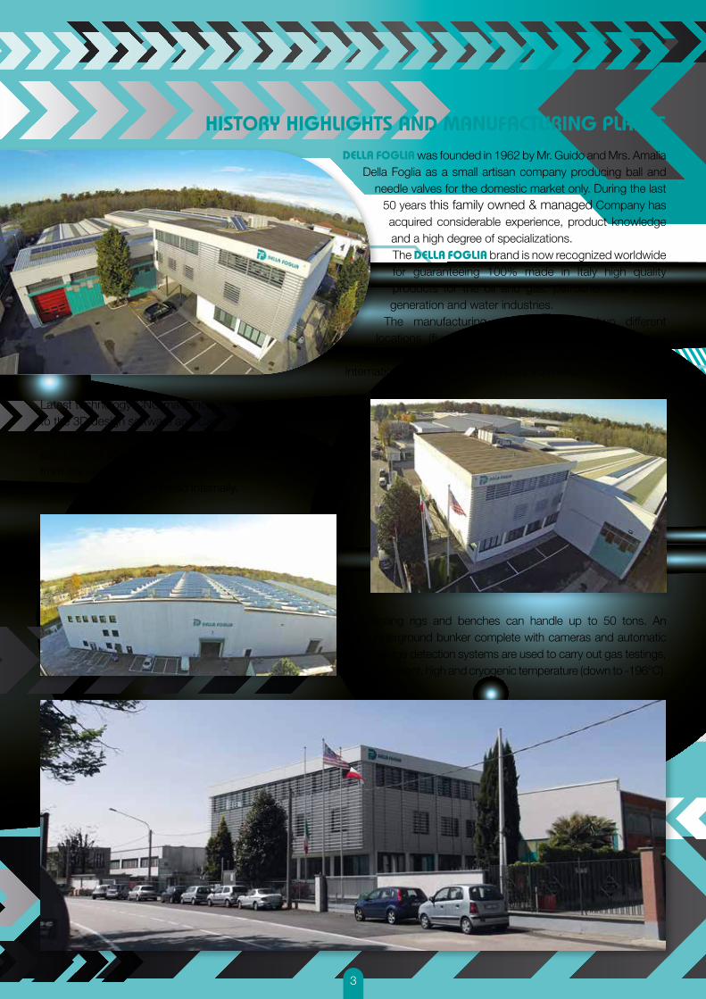
DELLA FOGLIA was founded in 1962 by Mr. Guido and Mrs. Amalia Della Foglia as a small artisan company producing ball and
needle valves for the domestic market only. During the last 50 years this family owned & managed Company has acquired considerable experience, product knowledge and a high degree of specializations.The DELLA FOGLIA brand is now recognized worldwide for guaranteeing 100% made in Italy high quality products for the oil and gas, petrochemical, power generation and water industries.
The manufacturing plant, based in two different locations (five buildings for a total of 40.000 square
meters) is located in Italy, 20 minutes from Milan Malpensa International Airport and 30 minutes from Milan’s city centre.
Latest technology CNC machines are real-time connected to the 3D design software and Cad CAM. An ERP system combined with a barcode tracking system are installed to ensure the full traceability of the product from the receipt of raw materials to the shipment. Valves from ½” to 64” are machined internally.
Testing rigs and benches can handle up to 50 tons. An underground bunker complete with cameras and automatic leakage detection systems are used to carry out gas testings, at ambient, high and cryogenic temperature (down to -196°C).
HISTORY HIGHLIGHTS AND MANUFACTURING PLANTS

4

5
6
MAIN FEATURES OF BALL VALVES
DOUBLE BLOCK AND BLEEDWith this valve design, it is possible to isolate the valve body cavity between two valve seats and to safely drain/vent it, even when the line is in pressure. It is also called “on-line leak detection system” when the ball is in closed position and the body cavity is vented (in proper procedure). This makes it possible to check for seat leakages from the body vent connection. (1)
ANTISTATIC DEVICETo avoid any dangerous effects caused by static electricity charges, all Della Foglia ball valves incorporate an antistatic device to keep electric continuity between body, stem and ball. This is generally achieved by using springs (stem and/or trunnion to ball) or spring energized balls (stem to body).
ANTI-BLOWOUT STEMAs a safety feature, the valve is designed to avoid the blowout of the stem during the disassembly of the packing when pressure is trapped in the body cavity.
FIRE SAFE DESIGNTo limit leakage in case of fire, our valves are provided with a secondary seal, metallic or graphite based, in all the sealing points. Fire tests according to API 607, API 6FA and EN ISO 10497 have already been performed to certify the entire range of valves.
SELF-RELIEVING SEATSThe self-relieving seats are designed to vent to the line any excessive build-up pressure in the body cavity. Refer to the explanation “Single Piston Effect (self-relieving) vs. Double Piston Effect”.
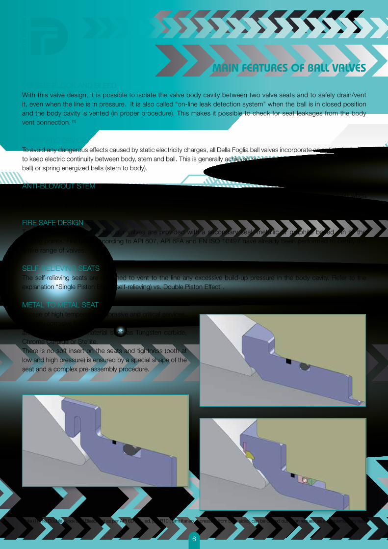
METAL TO METAL SEATIn case of high temperature, abrasive and critical services, or highly corrosive fluid the seating surfaces of ball and seats are coated with hard material such as Tungsten carbide, Chrome Carbide or Stellite. There is no soft insert on the seats and tightness (both at low and high pressure) is ensured by a special shape of the seat and a complex pre-assembly procedure.
Note (1) The Double Block and Bleed test as per API 6D XXIII ed. par B10 ( simultaneous pressure from both sides) can be carried out upon request as a supplementary test.
7
MAIN FEATURES OF BALL VALVES
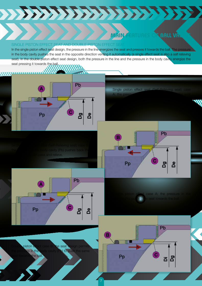
SINGLE PISTON EFFECT SEAT AND DOUBLE PISTON EFFECT SEATIn the single piston effect seat design, the pressure in the line energizes the seat and presses it towards the ball. The pressure in the body cavity pushes the seat in the opposite direction venting it automatically (a single effect seat is also a self relieving seat). In the double piston effect seat design, both the pressure in the line and the pressure in the body cavity energize the seat pressing it towards the ball.
Single piston effect seat (Self-Relieving seat) case A: the pressure in the pipeline (Pp) pushes the seat towards the ball.
Single piston effect seat (Self-Relieving seat) case B: the pressure in the body cavity (Pb) pushes back the seat; the fluid can pass and relieve.
Double piston effect case A: the pressure in the pipeline (Pp) pushes the seat towards the ball.
Double piston effect case B: the seat design permits the pressure in the body cavity (Pb) to push the same seat towards the ball.

8
MAIN FEATURES OF BALL VALVES
GREASE INJECTION DEVICESUpon request our valves can be equipped with grease injection devices on stem and/or seats. This feature pumps sealant to restore tightness in case of damaged sealing materials in the stem area or in the seat area. The injection devices are very helpful as preventive maintenance as well as preservation procedure (refer to our product manual). Della Foglia can provide a wide range of products for flushing, lubricating, greasing and sealing.
LININGThe ball valve’s internal wetted parts can undergo a special coating process which protects the components with an epoxy film (thickness may be up to 1500 mic). This process may help in case of high corrosion.
EXTENDED BONNET Extended bonnets are used in either high or low temperature applications in order to move the stem sealing packing as far as possible from the fluid (which is at low/high temperature).The extension length is calculated by Della Foglia engineers based on the actual service conditions or can be adjusted based on the customer’s specifications.
STEM EXTENSIONSStem extensions bring at the requested height all the operation features, such as gears actuators, sealant injectors, vent and drain valves etc. They are normally requested when the valves are installed in underground line.
WELD OVERLAYSWhen it is required to improve the corrosion resistance of the base material and/or the mechanical performances of a component, it is possible to place a weld overlay of CRA materials (stainless steel or incoloy) on the sealing areas only or on all the wetted parts.The parts undergo a pre-machining process, followed by the welding activity and the final machining. The welding is carried out by qualified welders and it is controlled by certified NDE personnel.
LOW EMISSION VALVESUse of special seals and the accurate machining of stem and bonnet sealing areas ensure the compliance with the “low fugitive emission” regulations. Specially designed stem and body joint seals, available upon request, satisfy the most stringent fugitive emission requirements also in low and high temperature.We can provide several types of sealing systems which vary from multiple elastomers, pressure energized seals, mechanically energized seals and metallic seals.
APPLICABLE STANDARDSThe design, manufacturing and testing of Della Foglia Ball valves are generally in accordance with the following standards, however, we can provide tailor made products based on any kind of specification or international standard.
API 6AAPI 6DAPI 6DSSAPI 607API 6FAAPI 598
ASME B16.5ASME B16.10ASME B16.25ASME B16.34ASME B16.47ASME B31.3ASME B31.4ASME B31.8ASME II – V - VIII
ISO 9001-2000ISO 10497ISO 15156ISO 5211ISO 17292ISO 15848
NACE MR-01-75DIRECTIVE 97/23/ECDIRECTIVE 94/9/ECEN 12266BS 5351BS 6755
9
CERTIFICATIONS
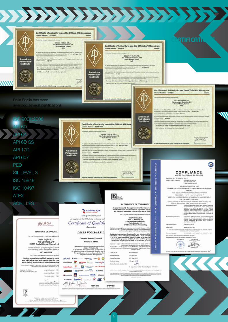
Della Foglia has beenawarded several certificationsincluding but not limited to:
ISO 9001:2008
API 6D
API 6A
API 6D SS
API 17D
API 607
PED
SIL LEVEL 3
ISO 15848
ISO 10497
ATEX
ACHILLES
10
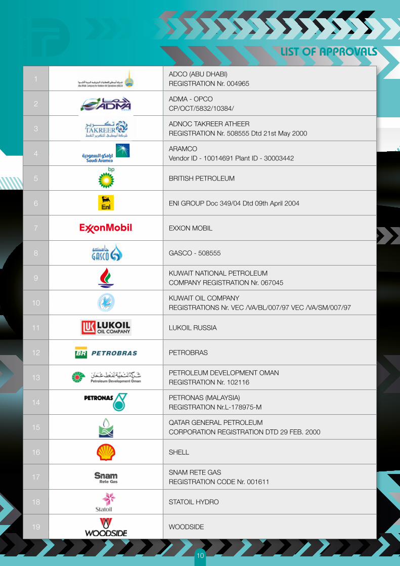
LIST OF APPROVALS
1ADCO (ABU DHABI)REGISTRATION Nr. 004965
2ADMA - OPCOCP/OCT/5832/10384/
3ADNOC TAKREER ATHEERREGISTRATION Nr. 508555 Dtd 21st May 2000
4ARAMCOVendor ID - 10014691 Plant ID - 30003442
5 BRITISH PETROLEUM
6 ENI GROUP Doc 349/04 Dtd 09th April 2004
7 EXXON MOBIL
8 GASCO - 508555
9KUWAIT NATIONAL PETROLEUMCOMPANY REGISTRATION Nr. 067045
10KUWAIT OIL COMPANYREGISTRATIONS Nr. VEC /VA/BL/007/97 VEC /VA/SM/007/97
11 LUKOIL RUSSIA
12 PETROBRAS
13PETROLEUM DEVELOPMENT OMANREGISTRATION Nr. 102116
14PETRONAS (MALAYSIA)REGISTRATION Nr.L-178975-M
15QATAR GENERAL PETROLEUMCORPORATION REGISTRATION DTD 29 FEB. 2000
16 SHELL
17SNAM RETE GASREGISTRATION CODE Nr. 001611
18 STATOIL HYDRO
19 WOODSIDE

11
MAJOR PROJECTS REFERENCE LIST
END USERS CONTRACTOR PROJECT MATERIAL
1 Adco Snamprogetti Bu Hasa(U.A.E.)
3.000 valves from 1” up to 24” manual and actuated
2 ADMA OPCO HYUNDAY E. & C. Satah Al RazbootSARB package 4 (U.A.E.)
220 valves from 3” to 36” classes 150to 2500 manual operated
3 HYUNDAY E. & C. NPCC ZCSC Demothballing Project (U.A.E.)
46 actuated trunnion mounted valvesfrom 1” to 24”, classes from 150 to 2500
4 Aramco Metal Service Khuraish(Saudi Arabia) 7 pcs of 48” cl. 600
5 Aramco NPCC Khuraish(Saudi Arabia)
from 8” cl. 1500 up to 30” cl. 1500
6 Aramco / KNPC CCC Al-Khafji(Saudi Arabia / Kuwait) 3.000 valves from 1” up to 42”
7 BP AIBEL - UK In Amenas (Algeria) 112 trunnion mounted valves 6” 8” 10” class 1500 body in LTCS+welding overlay, metal seated
8 BP KBR Azeri Project - Baku(Azerbaijan)
7 pcs of 24” cl. 900 metal to metal actuated
9 BP PSN BP Dimlington OCTIP(UK) 200 valves from 2” up to 30” actuated
10 BP TECHNIPHOSUTON
BPTT Juniper project(Trinidad & Tobago)
35 valves from 2” to 10” classes from 150to 2500, soft and metal seated, actuated
11 ConocoPhillips Hang Tuah(Indonesia) 16” cl. 900 metal to metal subsea
12 GASCO Hyunday E & C Habshan 5 (U.A.E.) Trunnion and floating side entry, top entry and fully welded body size from 1”” up to 36”” cl. 150 to 600”
13 Karachaganak Petrofac Karachaganak 4th Stabilization & Sweeting Train (Kazakhstan)
500 valves manual and actuated from2” up to 24” exotic materials/lip seals
14 KOC Snamprogetti BS 131(Kuwait)
1.500 valves from 1” up to 24” manual and actuated
15 Maersk Oil Qatar McDERMOTT Al Shaheen FieldDevelopment Pj (Qatar) more than 2.000 valves
16 PEMEX GlobalOffshore Mexico Offshore Platform (Mexico) 2 valves 36”-600 metal seated
- leakage rate A
14 QATARPETROLEUM Petrofac Gas Sweeting at Mesaieed
& Dukhan (Qatar)897 trunnion mounted valves from 1,5” to 30” classes
from 150 to 1500, manual operated and actuated
18 RAS GAS CTJV (Chiyoda/Technip)
RGS Train 6 / 7, QGX(Qatar)
5.000 valves from 2” up to46” all ratings
19 RAS GAS HYUNDAI HEAVY INDUSTRIES Flow assurance (Qatar) 19 top entry double ball valves 6” API 6A
5000 metal seated for subsea service
20 RAS GAS JGCCorporation Barzan (Qatar) 112 trunnion mounted valves from 4” to 32” classes from 150 to 900,
side entry & top enty design + jacketed valves, soft & metal seated
21 Shell Aker Kvaerner LNG SLUG CATCHER(Nigeria)
Cryogenic valves from 16”up to 30”
22 Shell Amec LEMAN ALPHA COMPRESSIONUPGRADE PJ (UK)
Low temp. service valvesfrom 16” up to 24”
23 Sonatrach JGC Hassi R’MEL Boosting Project(Algeria) valves from 2” up to 12”
24 Sonatrach Saipem Sa Lpg Hassi Messaoud cryogenic ball valves from 1” up to 24”cl. 150 to cl. 900
25 Sonatrach SamsungEngineering Skikda cryogenic ball valves from 1” up to 20”
26 Statoil Aker Kvaerner Statfjord(Norway)
120 valves metal to metalfrom 2” up to 24” lip seals
27 TOTAL TOTAL UK Elgin Franklin (UK) 500 valves metal to metal from 2” up to 24” exotic materials/lip seals
12
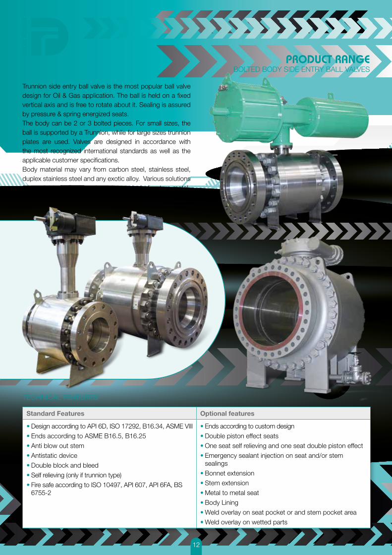
PRODUCT RANGEBOLTED BODY SIDE ENTRY BALL VALVES
Trunnion side entry ball valve is the most popular ball valve design for Oil & Gas application. The ball is held on a fixed vertical axis and is free to rotate about it. Sealing is assured by pressure & spring energized seats. The body can be 2 or 3 bolted pieces. For small sizes, the ball is supported by a Trunnion, while for large sizes trunnion plates are used. Valves are designed in accordance with the most recognized international standards as well as the applicable customer specifications. Body material may vary from carbon steel, stainless steel, duplex stainless steel and any exotic alloy. Various solutions are available for body seals and seats including true metal-to-metal contact sealing.
Standard Features Optional features
• Design according to API 6D, ISO 17292, B16.34, ASME VIII
• Ends according to ASME B16.5, B16.25
• Anti blow out stem
• Antistatic device
• Double block and bleed
• Self relieving (only if trunnion type)
• Fire safe according to ISO 10497, API 607, API 6FA, BS 6755-2
• Ends according to custom design
• Double piston effect seats
• One seat self relieving and one seat double piston effect
• Emergency sealant injection on seat and/or stem sealings
• Bonnet extension
• Stem extension
• Metal to metal seat
• Body Lining
• Weld overlay on seat pocket or and stem pocket area
• Weld overlay on wetted parts
TECHNICAL FEATURES
13
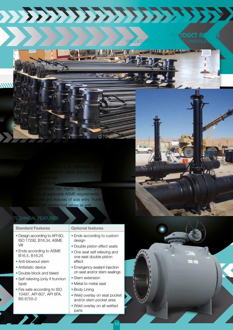
PRODUCT RANGEWELDED BODY BALL VALVES / UNDERGROUND
Fully welded ball valves are characterized by body fabricated by welding of forged rings.The result is a solid assembly with no leakage paths.A fully welded application is a preferable solution when no maintenance is scheduled on valves and when it is mandatory to avoid any external leakage.A typical application is for underground valves.Welding is performed by highly qualified professionals, in accordance with all applicable ASME requirements. The same options and features of side entry Trunnion ball valves are available for fully welded ball valves as well.
Standard Features Optional features
• Design according to API 6D, ISO 17292, B16.34, ASME VIII
• Ends according to ASME B16.5, B16.25
• Anti-blowout stem
• Antistatic device
• Double block and bleed
• Self relieving (only if trunnion type)
• Fire safe according to ISO 10497, API 607, API 6FA, BS 6755-2
• Ends according to custom design
• Double piston effect seats
• One seat self relieving and one seat double piston effect
• Emergency sealant injection on seat and/or stem sealings
• Stem extension
• Metal to metal seat
• Body Lining
• Weld overlay on seat pocket and/or stem pocket area
• Weld overlay on all wetted parts
TECHNICAL FEATURES

14
PRODUCT RANGETOP ENTRY BALL VALVES
Top Entry ball valve design is characterized by one piece body construction with top access to all internal components. Top Entry Ball Valves are the preferable solution when it is required to perform in line maintenance, and when the reduction of possible leakage path is mandatory. The body could be manufactured from forged billet or high quality castings. Same options and features of side entry Trunnion ball valve are available also for top entry ball valves.
TECHNICAL FEATURES
Standard Features Optional features
• Design according to API 6D, ISO 17292, B16.34, ASME VIII
• Ends according to ASME B16.5, B16.25
• Anti-blowout stem
• Antistatic device
• Double block and bleed
• Self relieving (only if trunnion type)
• Fire safe according to ISO 10497, API 607, API 6FA, BS 6755-2
• Ends according to custom design
• Double piston effect seats
• One seat self relieving and one seat double piston effect
• Emergency sealant injection on seat and/or stem sealings
• Stem extension
• Bonnet extension
• Metal to metal seat
• Body Lining
• Weld overlay on seat pocket and/or stem pocket area
• Weld overlay on all wetted parts

15
PRODUCT RANGESUBSEA VALVES
Della Foglia is one of the first worldwide companies to reach API 6DSS qualification for subsea pipeline ball valves. This proves the capability of Della Foglia to manufacture such critical products.Special design is developed for each application in order to guarantee the required performance level for the whole predicted life of the valve.A high level quality control inspection & test, as well as advanced design tools (finite element simulation, fatigue analysis, fluidodynamic study etc.) contribute to the increase in performance of the valves.An internal testing facility is available to perform hydrostatic and gas tests up to 1000bar pressure.
TECHNICAL FEATURES
Standard Features Optional features
• Design according to API 6DSS, ISO 17292, B16.34, ASME VIII
• Ends according to ASME B16.5, B16.25
• Anti-blowout stem
• Antistatic device
• Double block and bleed
• Self relieving (only if trunnion type)
• Fire safe according to ISO 10497, API 607, API 6FA, BS 6755-2
• Ends according to custom design
• Double piston effect seats
• One seat self relieving and one seat double piston effect
• Emergency sealant injection on seat and/or stem sealings
• Stem extension
• Bonnet extension
• Metal to metal seat
• Body Lining
• Weld overlay on seat pocket and/or stem pocket area
• Weld overlay on wetted parts
16
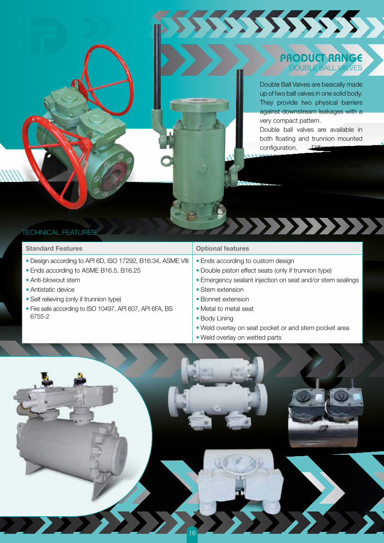
PRODUCT RANGEDOUBLE BALL VALVES
Double Ball Valves are basically made up of two ball valves in one solid body. They provide two physical barriers against downstream leakages with a very compact pattern.Double ball valves are available in both floating and trunnion mounted configuration. Different body constructions are available: one piece body (cartridge type), bolted body and fully welded body.A center bleed port between the valves allows testing of valve’s performance, and provides a “double block and bleed” feature with maximum safety.
TECHNICAL FEATURES
Standard Features Optional features
• Design according to API 6D, ISO 17292, B16.34, ASME VIII
• Ends according to ASME B16.5, B16.25
• Anti-blowout stem
• Antistatic device
• Self relieving (only if trunnion type)
• Fire safe according to ISO 10497, API 607, API 6FA, BS 6755-2
• Ends according to custom design
• Double piston effect seats (only if trunnion type)
• Emergency sealant injection on seat and/or stem sealings
• Stem extension
• Bonnet extension
• Metal to metal seat
• Body Lining
• Weld overlay on seat pocket or and stem pocket area
• Weld overlay on wetted parts

17
PRODUCT RANGEFLOATING BALL VALVES
Floating ball valves have a simple structure: the ball is supported by the seats but can float inside the valve body.Under medium pressure, the ball drifts towards the downstream side pushing against the seat ensuring sealing reliability.The range of Della Foglia Floating ball valves includes side entry, bolted body or threaded body, and the special top entry design.Materials of construction are carbon steel, stainless steel or any exotic alloy.
TECHNICAL FEATURES
Standard Features Optional features
• Design according to API 6D, ISO 17292, B16.34, ASME VIII
• Ends according to ASME B16.5, B16.25
• Anti-blowout stem
• Antistatic device
• Fire safe according to ISO 10497, API 607, API 6FA, BS 6755-2
• Ends according to custom design
• Bonnet extension
• Stem extension
• Metal to metal seat
• Body Lining

18
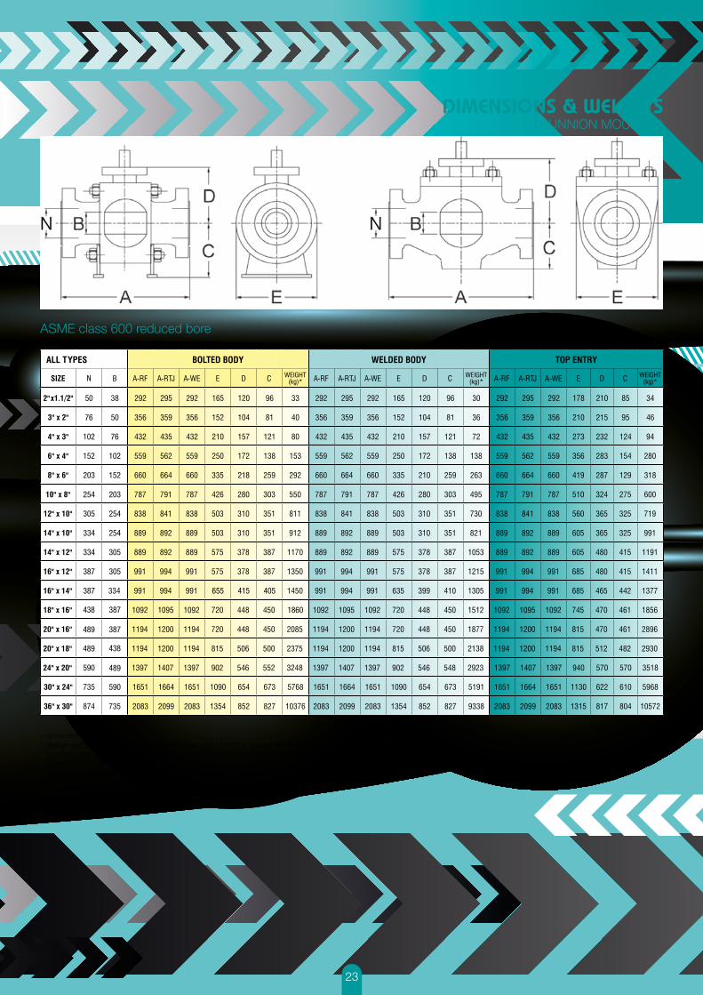
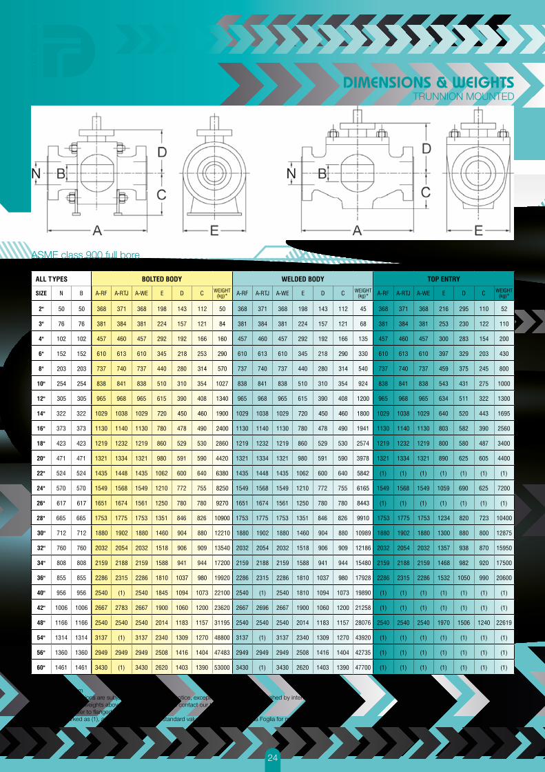
DIMENSIONS & WEIGHTSTRUNNION MOUNTED
ASME class 150 full bore
- dimensions in mm- design and dimensions are subject to change without notice, except the dimensions established by international standard - for dimension and weights above 60” up to 64”, please contact our technical department- weight figures refer to flanged valves- measures marked as (1), and larger sizes are not standard values. Please contact Della Foglia for more details
50 50 19
41
56
18
40
54
408
420 400 785
1178
480
408
480
420 400 865
1270
1415 827 830 8221
1510 10140
135381030977
1415 827 830 7700
1510 9450
135381030977
76
102
1387 1387
152
203
254
305
387
438
489
590
102
781
1458
387
438
489
590
781
1458
152
203
254
305
76

19
50 20
47
82
19
45
80
400 933420 400 850420
76 50
102 76
152 102
203 152
254 203
305
305
305
334
334
387
387
387
590
590
387
254
254
DIMENSIONS & WEIGHTSTRUNNION MOUNTED
ASME class 150 reduced bore
- dimensions in mm- design and dimensions are subject to change without notice, except the dimensions established by international standard - for dimension and weights above 60” up to 64”, please contact our technical department- weight figures refer to flanged valves- measures marked as (1), and larger sizes are not standard values. Please contact Della Foglia for more details

20
ASME class 300 full bore
- dimensions in mm- design and dimensions are subject to change without notice, except the dimensions established by international standard - for dimension and weights above 60” up to 64”, please contact our technical department- weight figures refer to flanged valves- measures marked as (1), and larger sizes are not standard values. Please contact Della Foglia for more details
DIMENSIONS & WEIGHTSTRUNNION MOUNTED
50 149 83 22
388 703
1050
3770
6200
11130
181001090 1090
400625
388
400625
56210
149 83 20
210
80
50
76
102
152
203
254
305
387
438
489
590
102
781
1458
387
438
489
590
781
1458
152
203
254
305
76

21
ASME class 300 reduced bore
- dimensions in mm- design and dimensions are subject to change without notice, except the dimensions established by international standard - for dimension and weights above 60” up to 64”, please contact our technical department- weight figures refer to flanged valves- measures marked as (1), and larger sizes are not standard values. Please contact Della Foglia for more details
DIMENSIONS & WEIGHTSTRUNNION MOUNTED
50 21
31105149
254
128
388
388
388
388
105149
254
128
20
30
625 1002 625
76 50
102 76
152 102
203 152
254 203
305
305
305
334
334
387
387
387
590
590
387
254
254

22
ASME class 600 full bore
- dimensions in mm- design and dimensions are subject to change without notice, except the dimensions established by international standard - for dimension and weights above 60” up to 64”, please contact our technical department- weight figures refer to flanged valves- measures marked as (1), and larger sizes are not standard values. Please contact Della Foglia for more details
DIMENSIONS & WEIGHTSTRUNNION MOUNTED
50 50 165 83
218 274
363510
965389
1315
1745
3242608907
4170
5187693
9746851
14021918
208051045
943
27800
43400
11801200 2610011801200
918
851
693
608
405415655
330363
389
218
510
83165
907
1170
1045
94315351535
1170
405415655
725330
76
102
152
203
254
305
387
438
489
590
102
781
1458
387
438
489
590
781
1458
152
203
254
305
76
23
ASME class 600 reduced bore
- dimensions in mm- design and dimensions are subject to change without notice, except the dimensions established by international standard - for dimension and weights above 60” up to 64”, please contact our technical department- weight figures refer to flanged valves- measures marked as (1), and larger sizes are not standard values. Please contact Della Foglia for more details
DIMENSIONS & WEIGHTSTRUNNION MOUNTED
50
218
655 415 405
1860
76 50
102 76
152 102
203 152
254 203
305
305
305
334
334
387
387
387
590
590
387
438
489
438
489
489
254
254
24
ASME class 900 full bore
- dimensions in mm- design and dimensions are subject to change without notice, except the dimensions established by international standard - for dimension and weights above 60” up to 64”, please contact our technical department- weight figures refer to flanged valves- measures marked as (1), and larger sizes are not standard values. Please contact Della Foglia for more details
DIMENSIONS & WEIGHTSTRUNNION MOUNTED
50 50
76
102
152
84
160
290
570
1340
314
218
1900
6380
8250
9270
10900
5842
6165
8443
9910
1037 980 1037 980
460450720 1800
1200
460
314
290
450720
2400
203
254
305
102
152
203
254
305
617 617
76

25
ASME class 900 reduced bore
- dimensions in mm- design and dimensions are subject to change without notice, except the dimensions established by international standard - for dimension and weights above 60” up to 64”, please contact our technical department- weight figures refer to flanged valves- measures marked as (1), and larger sizes are not standard values. Please contact Della Foglia for more details
DIMENSIONS & WEIGHTSTRUNNION MOUNTED
50
76 50
102 76
152 102
107
245
2065
9500
720
203 152
254 203
305
305
305
254
254

26
50
76
102
50
1015 1015
76
102
ASME class 1500 full bore
ASME class 2500 full bore
- dimensions in mm- design and dimensions are subject to change
without notice, except the dimensions establi-shed by international standard
- for dimension and weights above 60” up to 64”, please contact our technical department
- weight figures refer to flanged valves- measures marked as (1), and larger sizes are not
standard values. Please contact Della Foglia for more details
DIMENSIONS & WEIGHTSTRUNNION MOUNTED
143
157
193
297
336
379
511
519
530
626
672
803
941
1035
1060
1180
112
121
167
303
352
397
495
523
544
620
640
736
1037
1066
1165
1306
50
98
198
485
827
1507
2272
2850
4120
6150
7800
12355
13100
13600
15100
18840
451
578
673
914
1022
1270
1422
1651
1962
2134
2286
454
584
683
927
1038
1292
1445
1651
1962
2134
2286
451
578
673
914
1022
1270
1422
1651
1962
2134
2286
235
280
373
502
664
752
850
990
1100
1215
1325
180
206
259
345
424
475
544
630
720
810
900
136
161
211
355
427
475
535
580
670
740
825
110
212
406
1043
1672
2137
3210
5090
6160
8630
11640
42
62
87
131
179
223
265
292
333
374
419
42
62
87
131
179
223
265
292
333
374
419
451
578
673
914
1022
1270
1422
(1)
(1)
(1)
(1)
454
584
683
927
1038
1292
1445
(1)
(1)
(1)
(1)
451
578
673
914
1022
1270
1422
(1)
(1)
(1)
(1)
235
319
364
483
550
675
765
(1)
(1)
(1)
(1)
212
243
299
355
424
503
588
(1)
(1)
(1)
(1)
98
122
164
243
292
352
436
(1)
(1)
(1)
(1)
120
246
470
937
1410
2600
4200
(1)
(1)
(1)
(1)
201
230
293
245
465
574
520
550
565
592
650
660
100
122
164
416
273
330
427
456
487
527
630
640
56
153
278
600
1100
1438
2017
2612
3890
5100
6678
11700
143
157
193
297
336
379
511
519
530
626
672
803
941
1035
1060
1180
112
121
167
303
352
397
495
523
545
620
640
736
1037
1066
1165
1306
45
89
179
437
745
1357
2045
2565
3708
5700
7020
11120
11790
12240
13590
16956
27
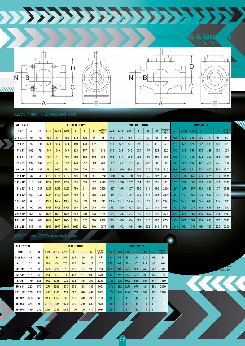
ASME class 1500 reduced bore
ASME class 2500 reduced bore
DIMENSIONS & WEIGHTSTRUNNION MOUNTED
50
76
102
51
60
134
700
48
53
120
160
88
670
1240355345502
300
50
600
76
102
- dimensions in mm- design and dimensions are subject to change
without notice, except the dimensions establi-shed by international standard
- for dimension and weights above 60” up to 64”, please contact our technical department
- weight figures refer to flanged valves- measures marked as (1), and larger sizes are not
standard values. Please contact Della Foglia for more details
42
62
87
131
179
223
265
333
374
419
38
42
62
87
131
179
223
265
292
333

28
- dimensions in mm- design and dimensions are subject to change without notice,
except the dimensions established by international standard - for dimension and weights above 60” up to 64”, please contact
our technical department- weight figures refer to flanged valves- measures marked as (1), and larger sizes are not standard
values. Please contact Della Foglia for more details
DIMENSIONS & WEIGHTSTRUNNION MOUNTED
API 6A 3000
API 6A 5000
API 6A 10000
29
- dimensions in mm- design and dimensions are subject to change without notice, except the dimensions established by international standard - for dimension and weights above 60” up to 64”, please contact our technical department- weight figures refer to flanged valves- measures marked as (1), and larger sizes are not standard values. Please contact Della Foglia for more details
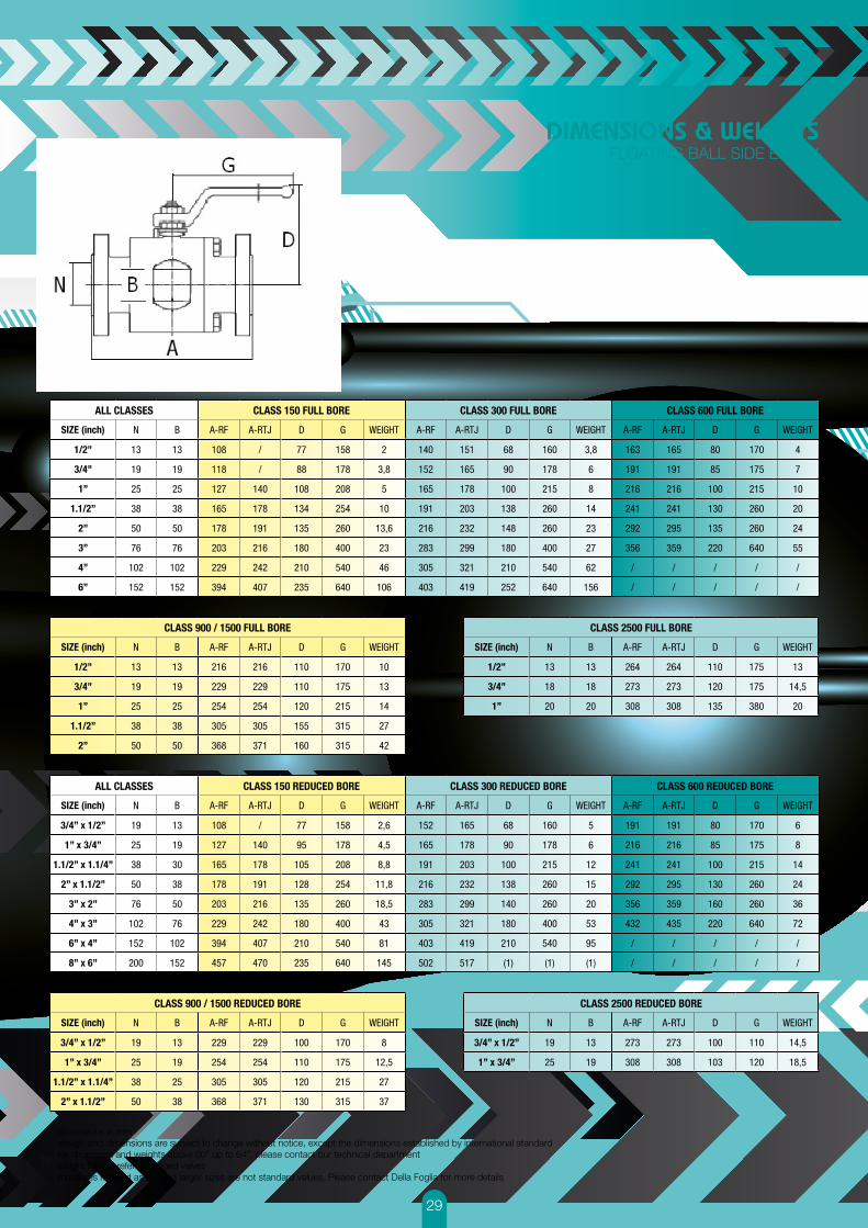
ALL CLASSES CLASS 150 FULL BORE CLASS 300 FULL BORE CLASS 600 FULL BORE
SIZE (inch) N B A-RF A-RTJ D G WEIGHT A-RF A-RTJ D G WEIGHT A-RF A-RTJ D G WEIGHT
1/2” 13 13 108 / 77 158 2 140 151 68 160 3,8 163 165 80 170 4
3/4” 19 19 118 / 88 178 3,8 152 165 90 178 6 191 191 85 175 7
1” 25 25 127 140 108 208 5 165 178 100 215 8 216 216 100 215 10
1.1/2” 38 38 165 178 134 254 10 191 203 138 260 14 241 241 130 260 20
2” 50 50 178 191 135 260 13,6 216 232 148 260 23 292 295 135 260 24
3” 76 76 203 216 180 400 23 283 299 180 400 27 356 359 220 640 55
4” 102 102 229 242 210 540 46 305 321 210 540 62 / / / / /
6” 152 152 394 407 235 640 106 403 419 252 640 156 / / / / /
ALL CLASSES CLASS 150 REDUCED BORE CLASS 300 REDUCED BORE CLASS 600 REDUCED BORE
SIZE (inch) N B A-RF A-RTJ D G WEIGHT A-RF A-RTJ D G WEIGHT A-RF A-RTJ D G WEIGHT
3/4” x 1/2” 19 13 108 / 77 158 2,6 152 165 68 160 5 191 191 80 170 6
1” x 3/4” 25 19 127 140 95 178 4,5 165 178 90 178 6 216 216 85 175 8
1.1/2” x 1.1/4” 38 30 165 178 105 208 8,8 191 203 100 215 12 241 241 100 215 14
2” x 1.1/2” 50 38 178 191 128 254 11,8 216 232 138 260 15 292 295 130 260 24
3” x 2” 76 50 203 216 135 260 18,5 283 299 140 260 20 356 359 160 260 36
4” x 3” 102 76 229 242 180 400 43 305 321 180 400 53 432 435 220 640 72
6” x 4” 152 102 394 407 210 540 81 403 419 210 540 95 / / / / /
8” x 6” 200 152 457 470 235 640 145 502 517 (1) (1) (1) / / / / /
CLASS 900 / 1500 FULL BORE
SIZE (inch) N B A-RF A-RTJ D G WEIGHT
1/2” 13 13 216 216 110 170 10
3/4” 19 19 229 229 110 175 13
1” 25 25 254 254 120 215 14
1.1/2” 38 38 305 305 155 315 27
2” 50 50 368 371 160 315 42
CLASS 900 / 1500 REDUCED BORE
SIZE (inch) N B A-RF A-RTJ D G WEIGHT
3/4” x 1/2” 19 13 229 229 100 170 8
1” x 3/4” 25 19 254 254 110 175 12,5
1.1/2” x 1.1/4” 38 25 305 305 120 215 27
2” x 1.1/2” 50 38 368 371 130 315 37
CLASS 2500 FULL BORE
SIZE (inch) N B A-RF A-RTJ D G WEIGHT
1/2” 13 13 264 264 110 175 13
3/4” 18 18 273 273 120 175 14,5
1” 20 20 308 308 135 380 20
CLASS 2500 REDUCED BORE
SIZE (inch) N B A-RF A-RTJ D G WEIGHT
3/4” x 1/2” 19 13 273 273 100 110 14,5
1” x 3/4” 25 19 308 308 103 120 18,5
DIMENSIONS & WEIGHTSFLOATING BALL SIDE ENTRY

30
- dimensions in mm- design and dimensions are subject to change without notice,
except the dimensions established by international standard - for dimension and weights above 60” up to 64”, please contact
our technical department- weight figures refer to flanged valves- measures marked as (1), and larger sizes are not standard
values. Please contact Della Foglia for more details
ALL CLASSES CLASS 150 / 300 FULL BORE CLASS 600 FULL BORE
SIZE (inch) N B A-RF A-RTJ D G A-RF A-RTJ D G
1/2” 13 13 140 151 95 130 163 165 95 130
3/4” 19 19 152 165 110 150 191 191 115 150
1” 25 25 165 178 125 150 216 216 125 150
1.1/2” 38 38 191 203 150 200 241 241 155 200
2” 50 50 216 232 175 210 292 295 165 310
ALL CLASSES CLASS 150 / 300 REDUCED BORE CLASS 600 REDUCED BORE
SIZE (inch) N B A-RF A-RTJ D G A-RF A-RTJ D G
3/4” x 1/2” 13 13 152 165 95 130 191 191 95 130
1” x 3/4” 19 19 165 178 110 150 216 216 115 150
1.1/2” x 1.1/4” 25 25 191 203 125 150 241 241 125 150
2” x 1.1/2” 38 38 216 232 150 200 292 295 155 200
3” x 2” 50 50 283 299 175 210 / / / /
DIMENSIONS & WEIGHTSFLOATING BALL TOP ENTRY
MATERIALS AVAILABLE FOR VALVESBOTH TRUNNION MOUNTED AND FLOATING BALL
31

Distributed by | Distribuido por :
TM
Life Flows on ™
WWW.ANYTHINGFLOWS.COM
Flow Control , our passion ®
SCAN ME