Research on the Critical Slope Stability Based on Two ... 2017...feasibility in slope engineering is...
5
Research on the Critical Slope Stability Based on Two Practical Procedures ZHANG Yu 1, 2, a, *, ZHANG Xiaodong 2, b , ZHAO Hai-bin 1, a , Jin Peijie 2, b 1 Hunan Provincial Key Laboratory of Hydropower Development Key Technology, Zhongnan Engineering Corporation, Changsha 410014, China; 2 College of Pipeline and Civil Engineering, China University of Petroleum, Qingdao, Shandong 266580, China a [email protected], b [email protected], Keywords: slope stability, Finite Arc Method, Strength Reduction Method, safety factor, critical slope Abstract: According to the element stresses, strains and displacements calculated by the Finite Difference Method (FDM), the Finite Arc Method based on the limit equilibrium theory and the Strength Reduction Method with deformation trend as the failure standard are established. The critical slip surface of slope and the minimum safety factor are obtained by the two new methods. A classical slope case is specialized to validate these methods and the feasibility in slope engineering is proved by the influence analysis of the results. 1. Introduction Slope stability analysis is the main basis to determine the stability of the slope, the necessity and the measurements of the reinforcement. It is a crucial research topic for geotechnical engineering recently [1, 2]. The main research includes the search for the critical slip surface and the calculation of anti-slide stability safety factor [3-5].This article starts with the present situation of slope stability analysis and introduces FDM into the search for critical slip surface and slope safety factor. According to the results of the element stress, strain and displacement, the practical procedures for the finite arc method (FAM) and the strength reduction method (SRM) have been applied in slope engineering availability. A classical slope case was chosen to validate this method and the feasibility in slope engineering is proved by the influence analysis of the results. Therefore, the established methods are considerably accurate and rational that they can compensate for the insufficiencies of existing methods. 2. FAM and SRM 2.1 Finite Arc Method In order to evaluate the slope stability, the results of the element stress, strain and displacement obtained from the calculation of FAM have been introduced into the search for critical slip surface and slope safety factor (F s ). It has reduced some unnecessary assumptions, taken into account the complex constitutive relation of rock and soil and acquired the slope stability under the complicated geology and environmental disturbance. 2017 2nd International Conference on Mechatronics and Information Technology (ICMIT 2017) Copyright © (2017) Francis Academic Press , UK 131
Transcript of Research on the Critical Slope Stability Based on Two ... 2017...feasibility in slope engineering is...

Research on the Critical Slope Stability Based on Two Practical Procedures
ZHANG Yu1, 2, a, *, ZHANG Xiaodong2, b, ZHAO Hai-bin1, a, Jin Peijie2, b 1Hunan Provincial Key Laboratory of Hydropower Development Key Technology, Zhongnan Engineering
Corporation, Changsha 410014, China; 2College of Pipeline and Civil Engineering, China University of Petroleum, Qingdao, Shandong 266580,
China [email protected], [email protected],
Keywords: slope stability, Finite Arc Method, Strength Reduction Method, safety factor, critical slope
Abstract: According to the element stresses, strains and displacements calculated by the Finite Difference Method (FDM), the Finite Arc Method based on the limit equilibrium theory and the Strength Reduction Method with deformation trend as the failure standard are established. The critical slip surface of slope and the minimum safety factor are obtained by the two new methods. A classical slope case is specialized to validate these methods and the feasibility in slope engineering is proved by the influence analysis of the results.
1. Introduction Slope stability analysis is the main basis to determine the stability of the slope, the necessity and
the measurements of the reinforcement. It is a crucial research topic for geotechnical engineering recently [1, 2]. The main research includes the search for the critical slip surface and the calculation of anti-slide stability safety factor [3-5].This article starts with the present situation of slope stability analysis and introduces FDM into the search for critical slip surface and slope safety factor. According to the results of the element stress, strain and displacement, the practical procedures for the finite arc method (FAM) and the strength reduction method (SRM) have been applied in slope engineering availability. A classical slope case was chosen to validate this method and the feasibility in slope engineering is proved by the influence analysis of the results. Therefore, the established methods are considerably accurate and rational that they can compensate for the insufficiencies of existing methods.
2. FAM and SRM 2.1 Finite Arc Method
In order to evaluate the slope stability, the results of the element stress, strain and displacement obtained from the calculation of FAM have been introduced into the search for critical slip surface and slope safety factor (Fs). It has reduced some unnecessary assumptions, taken into account the complex constitutive relation of rock and soil and acquired the slope stability under the complicated geology and environmental disturbance.
2017 2nd International Conference on Mechatronics and Information Technology (ICMIT 2017)
Copyright © (2017) Francis Academic Press , UK 131
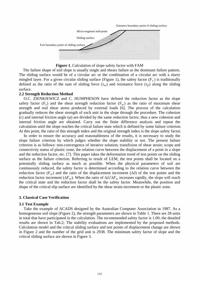
Figure 1. Calculation of slope safety factor with FAM
The failure shape of soil slope is usually single and shears failure as the dominant failure pattern. The sliding surface would be of a circular arc or the combination of a circular arc with a slurry mingled layer. For a given circular sliding surface (Figure 1), the safety factor (Fs ) is traditionally defined as the ratio of the sum of sliding force (τni) and resistance force (τfi) along the sliding surface. 2.2 Strength Reduction Method
O.C. ZIENKIEWICZ and C. HUMPHESON have defined the reduction factor as the slope safety factor (Fs ) and the shear strength reduction factor (Fsr ) as the ratio of maximum shear strength and real shear stress produced by external loads [6]. The process of the calculation gradually reduces the shear strength of each unit in the slope through the procedure. The cohesion (c) and internal friction angle (φ) are divided by the same reduction factor, thus a new cohesion and internal friction angle are obtained. Carry out the finite difference analysis and repeat the calculation until the slope reaches the critical failure state which is defined by some failure criterion. At this point, the ratio of this strength index and the original strength index is the slope safety factor.
In order to ensure the accuracy and reasonableness of the results, it is necessary to study the slope failure criterion by which judges whether the slope stability or not. The present failure criterion is as follows: non-convergence of iterative solution; transfixion of shear strain; scope and connectivity status of plastic zone; the relation curve between the displacement of a point in a slope and the reduction factor, etc. [7]. This paper takes the deformation trend of test points on the sliding surface as the failure criterion. Referring to result of LEM, the test points shall be located on a potentially sliding surface as much as possible. When the physical parameters of soil are continuously reduced, the safety factor is determined according to the relation curve between the reduction factor (Fsr) and the ratio of the displacement increment (∆δ) of the test points and the reduction factor increment (∆Fsr). When the ratio of ∆δ ∆Fsr⁄ increases rapidly, the slope will reach the critical state and the reduction factor shall be the safety factor. Meanwhile, the position and shape of the critical slip surface are identified by the shear strain increment or the plastic zone.
3. Classical Case Verification 3.1 Test Example
Take the example of ACADS designed by the Australian Computer Association in 1987. As a homogeneous soil slope (Figure 2), the strength parameters are shown in Table 1. There are 28 units in total that have participated in the calculation. The recommended safety factor is 1.00; the detailed results are shown in Tab.2; The stability evaluations are implemented by the proposed methods. Calculation model and the critical sliding surface and test points of displacement change are shown in Figure 2 and the number of the grid unit is 2938. The minimum safety factor of slope and the critical sliding surface are shown in Figure 3.
Entrance boundary point of sliding surface
Micro-segment mid-point
Sliding surface
Exit boundary point of sliding surface
132

(a) (b)
Figure 2. Calculation model of the examined slope (unit:m) (a:Shape and position of dangerous slide surface, b: Model mesh generation and test point arrangement)
Table 1. Mechanical parameters for the examined case Natural density γ (kN·m3)
Deformation modulus E (MPa)
Poisson ratio µ
Shear strength c (kPa) ϕ (°)
20.0 10.0 0.25 3.0 19.6
Table 2. Total results for the examined Factor of safety Factor of safety was obtained through determinant procedure
Mean Min Max Donald EMU Fredlud
0.991 0.940 1.080 1.000 1.000 0.990
Figure 4. Calculation results of slope
Based on practical procedure of FAM, 6486 potential arc slip surfaces were sought. The searched
minimum safety factor is 1.011146. Take Fsr=0.7 as the initial position, the displacement fields is obtained corresponding to different parameters by gradually increasing the reduction factor. According to the relation curve between the ∆δ ∆Fsr⁄ and Fsr , when 0.7≤Fsr≤1.016 , the displacement has a very slight increase with the decrease of shear strength. The curve basically appears to be a horizontal straight line and the slope is in a steady state. When Fsr=1.016, the displacement increases significantly with the decrease of shear strength. At this time the shear strain increment of the slope and the plastic zone gradually concentrated. It shows a transfixion distribute from the toe to the top of the slope where sliding force is basically the same as the resistance force. The slope may slip along this region, and the position and shape of the sliding surface are obtained by linking the region and the safety factor when it is 1.016. The results suggest that the safety factor calculated by the two methods is relatively close to the recommended values, and the critical slip surface is also basically the same. In this case, the feasibility of the method is verified. 3.2 Influence of parameters on Computational Results
The accuracy and reasonableness of the method are verified, and the effects of the different computational mesh, the cohesion (c) and internal friction angle (φ), the elastic modulus (E) and the
Dangerous slide surface
Test point a
Test point b
0 5
10 15 20 25
0.7 0.8 0.9 1.0 1.1 1.2 1.3
监测点 1 监测点 2
∆δ/∆F
sr
Fs = Fsr = 1.016
Strength reduction coefficient Fsr
Test point aTest point b
The finite arc method (FAM) The strength reduction method (SRM)
133

Poisson’s ratio (μ) on the results are examined as well. In addition, a comparable analysis on the results is applied by the Simplified Bishop Method (SBM), and the results are shown in Figure 4.
By comparing results of LAM、SRM and SBM under different influencing factors, it can be seen that cohesion, internal friction angle and number of mesh affect the results seriously, but the elastic modulus and Poisson’s ratio slightly. Moreover, the effect of cohesion and internal friction angle on the three methods is basically consistent and the safety factor has the trend to increase with the growth of the values of cohesion and internal friction angle. Elastic modulus and Poisson’s ratio have almost no impact on the SRM and FAM. The entire safety factors are between 0.995-1.045 and agree with the error requirement. Therefore, the results by the methods satisfy the requirements of stability analysis.
In summary, the stability analysis method in this paper which has considered the constitutive relation of rocks and soil material can reflect the authentic mechanical behaviour with high accuracy. It is reasonable and feasible to be applied in the actual slope project.
(a) Number of meshes (b) Cohesion
(c) Internal friction angle (d) Elastic modulus
(e) Poisson's ratio
Figure 4. Parameters influence on computation result
4. Discussion and Conclusion (1) Based on the results of stress, strain and displacement, the FAM and SRM are established
and corresponding computation procedure is developed. And the deficiencies of LEM and FDM are compensated.
(2) The feasibility and effectiveness are verified with a classical case, which shows that the critical slip surface and the minimum safety factor are agreed with recommended values, and the
0.95
1.00
1.05
1.10
1.15
1.20
0 1000 2000 3000 4000 5000
Fact
or o
f saf
ety
Number of meshes
FAM SRM
0.80
0.90
1.00
1.10
1.20
0 1 2 3 4 5 6
Fact
or o
f saf
eyty
Cohesion c/KPa
SBM FAM SRM
0.80
0.90
1.00
1.10
1.20
1.30
15 17 19 21 23 25
Fact
or o
f saf
ety
Internal friction angle φ(°)
SBM FAM SRM
1.00
1.01
1.02
1.03
1.04
1.05
5 6 7 8 9 10 11 12 13 14 15
Fact
or o
f saf
ety
Elastic modulus E/MPa
FAM SRM
0.99
1.00
1.01
1.02
1.03
1.04
1.05
0.10 0.15 0.20 0.25 0.30 0.35 0.40
Fact
or o
f saf
ety
Poisson ratio μ
FAM SRM
134

effect of different factors on the results conforms to the objective principles. Therefore, the methods have high accuracy and allow to be served to describe authentic mechanical behaviour.
5. Acknowledgments This work is supported by the Open Research Fund of Hunan Provincial Key Laboratory of
Hydropower Development Key Technology (No. PKLHD201601), Applied Basic Research Programs of Qingdao (17-1-1-33-jch), and supported by Fundamental Research Funds for the Central Universities (No. 16CX05002A).
References [1] E. HOEK, J. BRAY. (1981): Rock slope engineering. 3rd ed. London: Institution of Mining and Metallurgy. [2] J.A. Hudson. (1992): Rock Engineering Systems: Theory and Practice. Ellis Horwood Series in Civil Engineering, Geotechnics, New York: Ellis Horwood. [3] L.L.W. Abramson, T.S. Lee, S. Sharma, et al. (1996): Slope stability and stabilization methods. New York: Springer. [4] D.V. Griffiths, P.A. Lane. (1999): Slope stability analysis by finite elements. Géotechnique, vol. 49(3), pp. 387-403. [5] Y.M. CHEN, Y.C. LI, D.S. LING. (2004): Locating critical slip surfaces by a method combining monte Carlo technique and FEM. Rock and Soil Mechanics, vol. 25(2), pp. 75-80. [6] O.C. ZIENKIEWICZ, C. HUMPHESON, W. LEWISR. (1975): Associated and non-associated visco-plasticity and plasticity in solid mechanics. Geotechnique, vol. 25(4), pp. 671-689. [7] W.Y. XU, W. XIAO. (2007): Study on slope failure criterion based on strength reduction and gravity increase method. Rock and Soil Mechanics. vol. 28(3), pp. 505-511.
135