Reconfigggurable Analog Electronics using the...
20
Reconfigurable Analog Electronics using the Memristor* R Jacob Baker and Kristy A Campbell R. Jacob Baker and Kristy A. Campbell Department of Electrical and Computer Engineering [email protected] Practical reconfigurable analog design using the M it Memristor Minimize the stress across the Memristor device Programming/erasing the Memristor must be simple and reliable Biggest potential impact is found in circuits for Analog trimming Dt i Data conversion Communications Compensation for physical variations (temperature, sensor Baker/Campbell, June 27, 2011 conditioning, etc.) *This work supported by the Air Force Research Laboratory 1
Transcript of Reconfigggurable Analog Electronics using the...

Reconfigurable Analog Electronics g gusing the Memristor*
R Jacob Baker and Kristy A CampbellR. Jacob Baker and Kristy A. CampbellDepartment of Electrical and Computer Engineering
Practical reconfigurable analog design using the M i tMemristor Minimize the stress across the Memristor device Programming/erasing the Memristor must be simple and reliableg g g p
Biggest potential impact is found in circuits for Analog trimming
D t i Data conversion Communications Compensation for physical variations (temperature, sensor
Baker/Campbell, June 27, 2011
conditioning, etc.)*This work supported by the Air Force Research Laboratory
1

P i /E i th M i tProgramming/Erasing the Memristor Drive PE (below) high Drive PE (below) high
To erase, connect PE Voltage to a negative potential, for example, < -250 mV
To program connect PE To program connect PE to a positive potential > 250 mV
Package containing 12 Memristors fabricated at Boise State University.
Baker/Campbell, June 27, 2011
fabricated at Boise State University.
2

Key PointsKey Points Resistance of the Memristor can be scaled
downwards by increasing cross-sectional device area
Larger area results in more consistent devicesdevices
Memory resistance retention improved by minimizing the voltage across the deviceminimizing the voltage across the device. Ideally voltage across the device is 0 when
using the device!
Baker/Campbell, June 27, 2011
using the device!
3

B i B t M lti li R fBasic Beta-Multiplier Reference
M2 is made K-times wider than M1, in other words its Beta is multiplied up
REFI
hence the name Beta-Multiplier Reference (BMR).
REFDDDD IIIII 4321 REFDDDD 4321
memristorDGSTHND
GS RIVVIV 221
1 2
22
12
112
KWKPR
IREF
Baker/Campbell, June 27, 2011
1
12 KL
KPR nmemristorIndependent of VDD!Dependent on Rmemristor 4

Nanometer CMOS BMR ReferenceNanometer CMOS BMR Reference using the Memristor
Add amplifier to Add amplifier to ensure better power supply insensitivity
Add start-up circuit p Program/Erase by
driving PE signal high and applying a “ ”“PE Voltage”
Do we minimize the voltage across the Memristor duringMemristor during non-PE operation?
Does the resulting reference current
Baker/Campbell, June 27, 2011
vary with changes in VDD?
5

Variation of current with Rmemristor inVariation of current with Rmemristor in 50 nm CMOS BMR
kRmemristor 10REFI
kRmemristor 50
kRmemristor 100
MR 1 kRmemristor 500
MRmemristor 1
Baker/Campbell, June 27, 2011
VDD6

Wh t i th lt R ?What is the voltage across Rmemristor?
VDD
Baker/Campbell, June 27, 2011
VDDRmemristor = 10k, 50k, 100k, 500k, and 1MEG
7

50 mV across Rmemristor is good but50 mV across Rmemristor is good but can we reduce this stress further?
Looking at the equation for the reference current (below) notice that if K goes to 1 the current goes to zero and thus so does the voltage across Rthus so does the voltage across Rmemristor
The result is reducing K reduces the stress across the device!
Dropping K from 4 to 2 causes the voltage across Rmemristor to drop from 50 to 25 mV
2
12
112
KWKPR
IREF
Baker/Campbell, June 27, 2011
1
12 KL
KPR nmemristor
8

Why is this approach to reconfigurable analog integrated circuits significant and how
is it used? Programmability is non-volatile The circuit is small The circuit is small Currents can be used for power supply
independent voltage generationindependent voltage generationDynamically scale data converter operating
rangerange Control oscillator frequency
U f l i PLL h kBaker/Campbell, June 27, 2011
Useful in PLLs, charge pumps, wake-up circuits, etc. 9

A Memristor-Controlled OscillatorA Memristor Controlled Oscillator using a Source-Coupled Topology Use the Memristor-programmed BMR to set, or control,
the frequency of an oscillatorP t ti l f l ti t hi h Potential for very low power operation at high-frequencies
Baker/Campbell, June 27, 201110
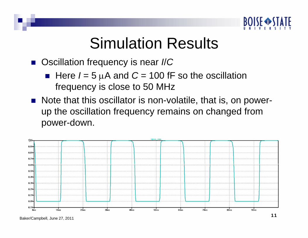
Simulation ResultsSimulation Results Oscillation frequency is near I/C
Here I = 5 A and C = 100 fF so the oscillation Here I = 5 A and C = 100 fF so the oscillation frequency is close to 50 MHz
Note that this oscillator is non-volatile, that is, on power-, , pup the oscillation frequency remains on changed from power-down.
Baker/Campbell, June 27, 201111

More Simulation ResultsMore Simulation Results Reducing, to 900 mV and increasing, to 1.1 V, shows
that the oscillation frequency doesn’t change much (not q y g (an exponential relationship as in many integrated oscillators).
VDD = 900 mV
VDD = 1.1 V
Baker/Campbell, June 27, 201112

Something simpler: A VoltageSomething simpler: A Voltage Divider
Use the Memristor-controlled current to generate Memristor -controlled voltages
Voltages tolerant to changes in the power supply voltage, VDD
Of course they are also non-Of course they are also nonvolatile meaning power can be removed and then re-applied without losing the programmed voltage values
Baker/Campbell, June 27, 201113
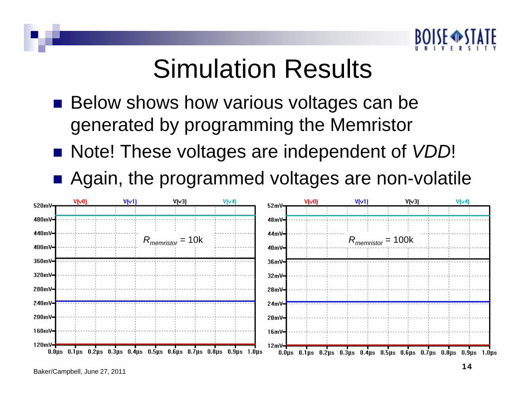
Simulation ResultsSimulation Results Below shows how various voltages can be
generated by programming the Memristorgenerated by programming the Memristor Note! These voltages are independent of VDD! Again the programmed voltages are non volatile Again, the programmed voltages are non-volatile
Rmemristor = 10k Rmemristor = 100k
Baker/Campbell, June 27, 201114

How Can Use this Simple VoltageHow Can Use this Simple Voltage Divider in a Complex Circuit?
Consider the Flash ADC seen at the left with simulation results shown below
Baker/Campbell, June 27, 201115

Reconfiguring the ADC’s inputReconfiguring the ADC s input range
What happens when the input signal amplitude shrinks?
We get fewer output codes thus the noise added to the input signal increases
Baker/Campbell, June 27, 201116

Quantization NoiseQuantization Noise The voltage dropped across each resistor in our simple
3-bit ADC is LSBVmVVDD125
This voltage, VLSB, is also the resolution of the ADC The RMS value of the quantization noise is give by
LSB8
12,LSB
RMSQeVV
The key point is that if we can reduce V we can reduce The key point is that if we can reduce VLSB we can reduce the quantization noise added to the input signal
Why not simply reduce the resistors or supply voltage y p y pp y gdriving the resistors to reduce the quantization noise? Answer: then our input signal range is reduced!
f f
Baker/Campbell, June 27, 2011
We want to be able to reconfigure the design for low noise and wide input signal range
17

Using the Memristor to reconfigureUsing the Memristor to reconfigure the input signal range - 1
Adding the Memristor-programmed BMR, Rmemristor = 10kO t t b l f l i t Output seen below for large input signal swings (same as before)
Baker/Campbell, June 27, 201118

Using the Memristor to reconfigureUsing the Memristor to reconfigure the input signal range - 2
The left trace again using R 10k shows how a The left trace, again using Rmemristor = 10k, shows how a reduction in the input signal results in no change in the ADC’s outputs!
Reconfiguring the input range allows the ADC’s output to swing through all of its codes reducing the added VQE,RMS
Rmemristor = 10k Rmemristor = 100k
Baker/Campbell, June 27, 201119

SummarySummary By incorporating the Memristor in the Beta-Multiplier
Reference (BMR) we showed that we canReference (BMR) we showed that we can Minimize the stress (voltage) across the device Use the Memristor to generate a non-volatile current that is
i d d t f VDDindependent of VDD
The Memristor-controlled BMR can then be used to Implement re configurable voltage references ADCs or Implement re-configurable voltage references, ADCs, or
any circuit that uses reference currents or voltages to control a characteristic of operation
Trimming currents or voltages for precision analog design, especially useful in nanometer CMOS where matching is poor (e g in a current steering DAC
Baker/Campbell, June 27, 2011
matching is poor (e.g., in a current steering DAC, removing the offset in an op-amp, etc.)
20