QRP MAG LOOP TUNER (80 20m) G8ODE · PDF fileThe QRP “ Loop ” Tuner during...
5
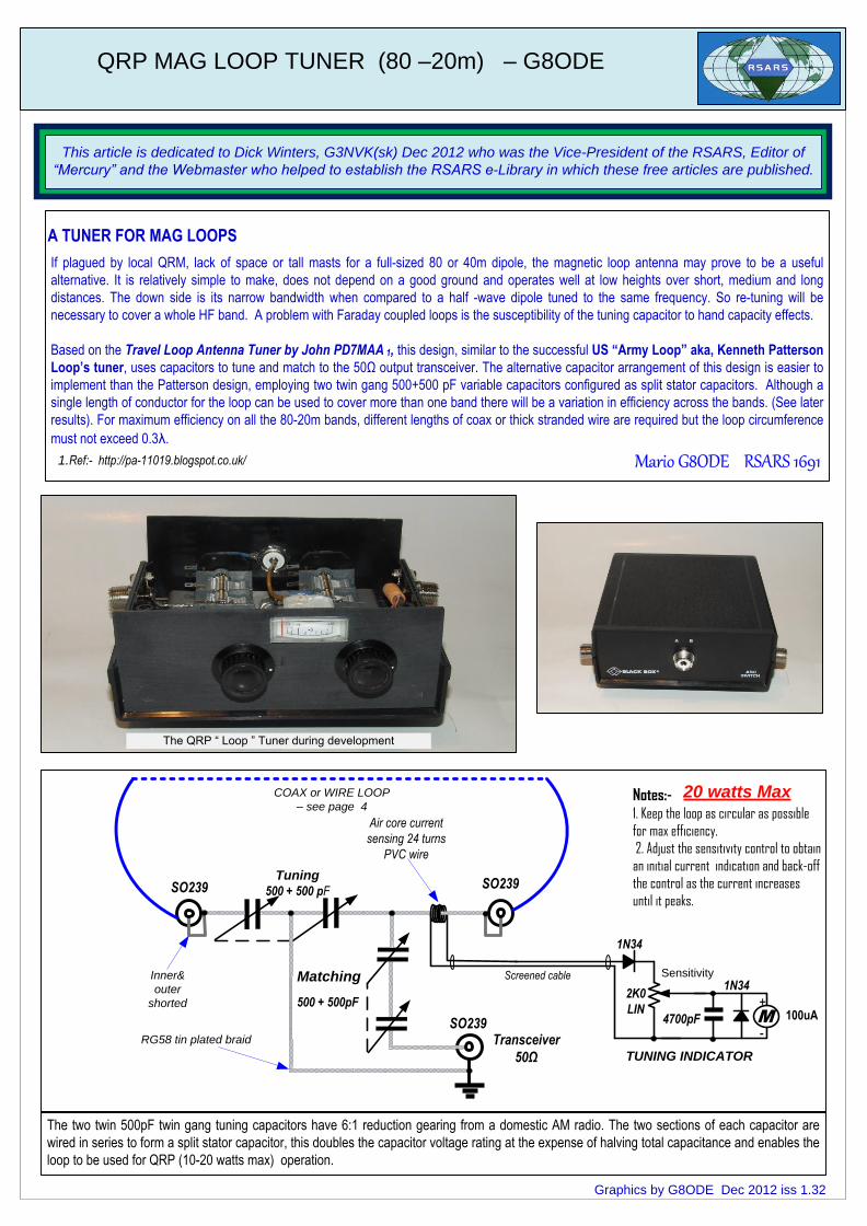
The QRP “ Loop ” Tuner during development The two twin 500pF twin gang tuning capacitors have 6:1 reduction gearing from a domestic AM radio. The two sections of each capacitor are wired in series to form a split stator capacitor, this doubles the capacitor voltage rating at the expense of halving total capacitance and enables the loop to be used for QRP (10-20 watts max) operation. QRP MAG LOOP TUNER (80 –20m) – G8ODE Graphics by G8ODE Dec 2012 iss 1.32 100uA 500 + 500pF Matching Transceiver 50Ω Tuning 500 + 500 pF SO239 1N34 2K0 LIN 4700pF TUNING INDICATOR + - Air core current sensing 24 turns PVC wire M SO239 Screened cable RG58 tin plated braid COAX or WIRE LOOP – see page 4 Inner& outer shorted 20 watts Max Notes:- 1. Keep the loop as circular as possible for max efficiency. 2. Adjust the sensitivity control to obtain an initial current indication and back-off the control as the current increases until it peaks. 1N34 Sensitivity This article is dedicated to Dick Winters, G3NVK(sk) Dec 2012 who was the Vice-President of the RSARS, Editor of “Mercury” and the Webmaster who helped to establish the RSARS e-Library in which these free articles are published. If plagued by local QRM, lack of space or tall masts for a full-sized 80 or 40m dipole, the magnetic loop antenna may prove to be a useful alternative. It is relatively simple to make, does not depend on a good ground and operates well at low heights over short, medium and long distances. The down side is its narrow bandwidth when compared to a half -wave dipole tuned to the same frequency. So re-tuning will be necessary to cover a whole HF band. A problem with Faraday coupled loops is the susceptibility of the tuning capacitor to hand capacity effects. Based on the Travel Loop Antenna Tuner by John PD7MAA 1, this design, similar to the successful US “Army Loop” aka, Kenneth Patterson Loop’s tuner, uses capacitors to tune and match to the 50Ω output transceiver. The alternative capacitor arrangement of this design is easier to implement than the Patterson design, employing two twin gang 500+500 pF variable capacitors configured as split stator capacitors. Although a single length of conductor for the loop can be used to cover more than one band there will be a variation in efficiency across the bands. (See later results). For maximum efficiency on all the 80-20m bands, different lengths of coax or thick stranded wire are required but the loop circumference must not exceed 0.3λ. Mario G8ODE RSARS 1691 SO239 1.Ref:- http://pa-11019.blogspot.co.uk/ A TUNER FOR MAG LOOPS
Transcript of QRP MAG LOOP TUNER (80 20m) G8ODE · PDF fileThe QRP “ Loop ” Tuner during...
The QRP “ Loop ” Tuner during development
The two twin 500pF twin gang tuning capacitors have 6:1 reduction gearing from a domestic AM radio. The two sections of each capacitor are
wired in series to form a split stator capacitor, this doubles the capacitor voltage rating at the expense of halving total capacitance and enables the
loop to be used for QRP (10-20 watts max) operation.
QRP MAG LOOP TUNER (80 –20m) – G8ODE
Graphics by G8ODE Dec 2012 iss 1.32
100uA500 + 500pF
Matching
Transceiver
50Ω
Tuning
500 + 500 pFSO239
1N34
2K0
LIN4700pF
TUNING INDICATOR
+
-
Air core current
sensing 24 turns
PVC wire
M
SO239
Screened cable
RG58 tin plated braid
COAX or WIRE LOOP
– see page 4
Inner&
outer
shorted
20 watts MaxNotes:-1. Keep the loop as circular as possible
for max efficiency.
2. Adjust the sensitivity control to obtain
an initial current indication and back-off
the control as the current increases
until it peaks.
1N34 Sensitivity
This article is dedicated to Dick Winters, G3NVK(sk) Dec 2012 who was the Vice-President of the RSARS, Editor of
“Mercury” and the Webmaster who helped to establish the RSARS e-Library in which these free articles are published.
If plagued by local QRM, lack of space or tall masts for a full-sized 80 or 40m dipole, the magnetic loop antenna may prove to be a useful
alternative. It is relatively simple to make, does not depend on a good ground and operates well at low heights over short, medium and long
distances. The down side is its narrow bandwidth when compared to a half -wave dipole tuned to the same frequency. So re-tuning will be
necessary to cover a whole HF band. A problem with Faraday coupled loops is the susceptibility of the tuning capacitor to hand capacity effects.
Based on the Travel Loop Antenna Tuner by John PD7MAA 1, this design, similar to the successful US “Army Loop” aka, Kenneth Patterson
Loop’s tuner, uses capacitors to tune and match to the 50Ω output transceiver. The alternative capacitor arrangement of this design is easier to
implement than the Patterson design, employing two twin gang 500+500 pF variable capacitors configured as split stator capacitors. Although a
single length of conductor for the loop can be used to cover more than one band there will be a variation in efficiency across the bands. (See later
results). For maximum efficiency on all the 80-20m bands, different lengths of coax or thick stranded wire are required but the loop circumference
must not exceed 0.3λ.
Mario G8ODE RSARS 1691
SO239
1.Ref:- http://pa-11019.blogspot.co.uk/
A TUNER FOR MAG LOOPS
SO239
Radio
SO239
SO239
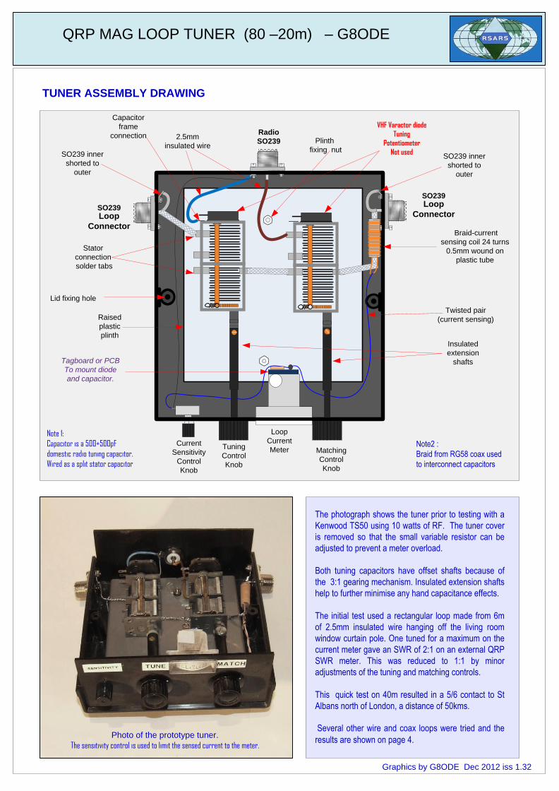
Note2 :
Braid from RG58 coax used
to interconnect capacitors
Loop
Current
Meter Matching
Control
Knob
Tuning
Control
Knob
Insulated
extension
shafts Tagboard or PCB
To mount diode
and capacitor.
Twisted pair
(current sensing)
Braid-current
sensing coil 24 turns
0.5mm wound on
plastic tube
SO239 inner
shorted to
outer
SO239 inner
shorted to
outer
Loop
ConnectorLoop
Connector
Raised
plastic
plinth
Lid fixing hole
Plinth
fixing nut
2.5mm
insulated wire
Stator
connection
solder tabs
Note 1:
Capacitor is a 500+500pF
domestic radio tuning capacitor.
Wired as a split stator capacitor
TUNER ASSEMBLY DRAWING
The photograph shows the tuner prior to testing with a
Kenwood TS50 using 10 watts of RF. The tuner cover
is removed so that the small variable resistor can be
adjusted to prevent a meter overload.
Both tuning capacitors have offset shafts because of
the 3:1 gearing mechanism. Insulated extension shafts
help to further minimise any hand capacitance effects.
The initial test used a rectangular loop made from 6m
of 2.5mm insulated wire hanging off the living room
window curtain pole. One tuned for a maximum on the
current meter gave an SWR of 2:1 on an external QRP
SWR meter. This was reduced to 1:1 by minor
adjustments of the tuning and matching controls.
This quick test on 40m resulted in a 5/6 contact to St
Albans north of London, a distance of 50kms.
Several other wire and coax loops were tried and the
results are shown on page 4.
VHF Varactor diode
Tuning
Potentiometer
Not used
QRP MAG LOOP TUNER (80 –20m) – G8ODE
Capacitor
frame
connection
Current
Sensitivity
Control
Knob
Photo of the prototype tuner.
The sensitivity control is used to limit the sensed current to the meter.
Graphics by G8ODE Dec 2012 iss 1.32
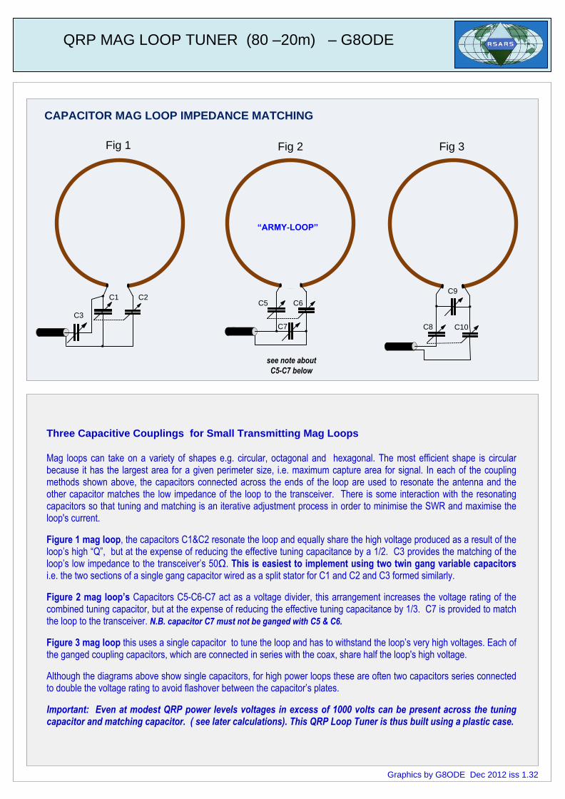
Three Capacitive Couplings for Small Transmitting Mag Loops
Mag loops can take on a variety of shapes e.g. circular, octagonal and hexagonal. The most efficient shape is circular because it has the largest area for a given perimeter size, i.e. maximum capture area for signal. In each of the coupling methods shown above, the capacitors connected across the ends of the loop are used to resonate the antenna and the other capacitor matches the low impedance of the loop to the transceiver. There is some interaction with the resonating capacitors so that tuning and matching is an iterative adjustment process in order to minimise the SWR and maximise the loop's current.
Figure 1 mag loop, the capacitors C1&C2 resonate the loop and equally share the high voltage produced as a result of the loop’s high “Q”, but at the expense of reducing the effective tuning capacitance by a 1/2. C3 provides the matching of the loop’s low impedance to the transceiver’s 50Ω. This is easiest to implement using two twin gang variable capacitors i.e. the two sections of a single gang capacitor wired as a split stator for C1 and C2 and C3 formed similarly.
Figure 2 mag loop’s Capacitors C5-C6-C7 act as a voltage divider, this arrangement increases the voltage rating of the combined tuning capacitor, but at the expense of reducing the effective tuning capacitance by 1/3. C7 is provided to match the loop to the transceiver. N.B. capacitor C7 must not be ganged with C5 & C6.
Figure 3 mag loop this uses a single capacitor to tune the loop and has to withstand the loop’s very high voltages. Each of the ganged coupling capacitors, which are connected in series with the coax, share half the loop's high voltage.
Although the diagrams above show single capacitors, for high power loops these are often two capacitors series connected to double the voltage rating to avoid flashover between the capacitor’s plates.
Important: Even at modest QRP power levels voltages in excess of 1000 volts can be present across the tuning capacitor and matching capacitor. ( see later calculations). This QRP Loop Tuner is thus built using a plastic case.
CAPACITOR MAG LOOP IMPEDANCE MATCHING
C1 C2
C3
“ARMY-LOOP”
QRP MAG LOOP TUNER (80 –20m) – G8ODE
C8 C10
C9
C5 C6
C7
see note about
C5-C7 below
Fig 1 Fig 2 Fig 3
Graphics by G8ODE Dec 2012 iss 1.32
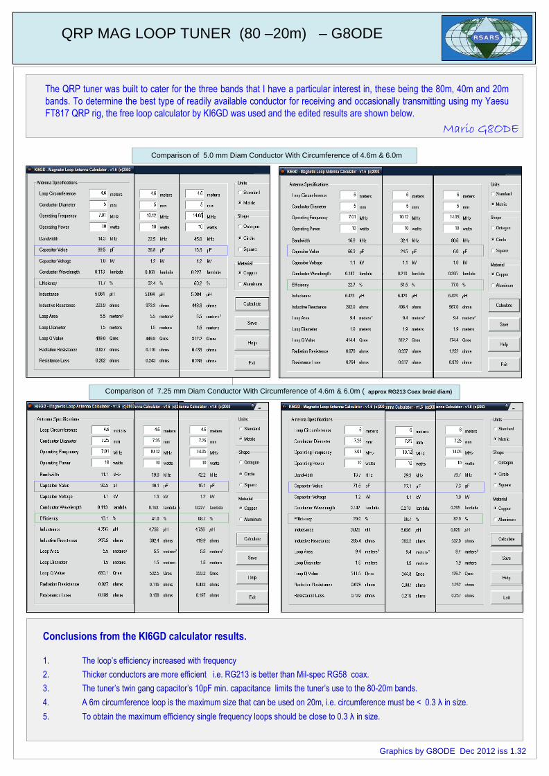
The QRP tuner was built to cater for the three bands that I have a particular interest in, these being the 80m, 40m and 20m
bands. To determine the best type of readily available conductor for receiving and occasionally transmitting using my Yaesu
FT817 QRP rig, the free loop calculator by KI6GD was used and the edited results are shown below.
0.3 λ in size.
Comparison of 5.0 mm Diam Conductor With Circumference of 4.6m & 6.0m
Comparison of 7.25 mm Diam Conductor With Circumference of 4.6m & 6.0m ( approx RG213 Coax braid diam)
QRP MAG LOOP TUNER (80 –20m) – G8ODE
Mario G8ODE
Conclusions from the KI6GD calculator results.
1. The loop’s efficiency increased with frequency
2. Thicker conductors are more efficient i.e. RG213 is better than Mil-spec RG58 coax.
3. The tuner’s twin gang capacitor’s 10pF min. capacitance limits the tuner’s use to the 80-20m bands.
4. A 6m circumference loop is the maximum size that can be used on 20m, i.e. circumference must be < 0.3 λ in size.
5. To obtain the maximum efficiency single frequency loops should be close to 0.3 λ in size.
Graphics by G8ODE Dec 2012 iss 1.32
QRP MAG LOOP TUNER (80 –20m) – G8ODE
Background to the US ARMY LOOP references.
References :-
1. ARRL QST March p17-18 & 150 “Lewis G. McCoy, W1ICP "The Army Loop in Ham Communications"
2. ARRL QST May 1968 p49-51 “The Army Loop” where KH Patterson replies”
3. RSGB Antenna Topics P19-20 “US Army Loop, Nov 1967 Pat Hawker G3VA”
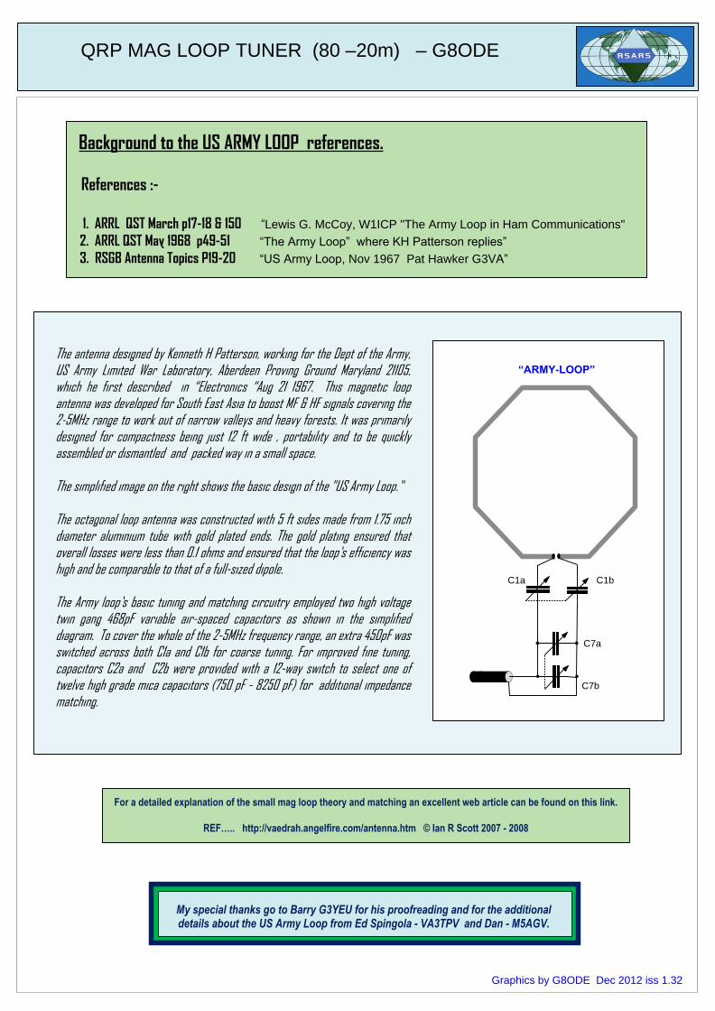
The antenna designed by Kenneth H Patterson, working for the Dept of the Army, US Army Limited War Laboratory, Aberdeen Proving Ground Maryland 21105, which he first described in “Electronics “Aug 21 1967. This magnetic loop antenna was developed for South East Asia to boost MF & HF signals covering the 2-5MHz range to work out of narrow valleys and heavy forests. It was primarily designed for compactness being just 12 ft wide , portability and to be quickly assembled or dismantled and packed way in a small space.
The simplified image on the right shows the basic design of the "US Army Loop.”
The octagonal loop antenna was constructed with 5 ft sides made from 1.75 inch diameter aluminium tube with gold plated ends. The gold plating ensured that overall losses were less than 0.1 ohms and ensured that the loop’s efficiency was high and be comparable to that of a full-sized dipole.
The Army loop’s basic tuning and matching circuitry employed two high voltage twin gang 468pF variable air-spaced capacitors as shown in the simplified diagram. To cover the whole of the 2-5MHz frequency range, an extra 450pF was switched across both C1a and C1b for coarse tuning. For improved fine tuning, capacitors C2a and C2b were provided with a 12-way switch to select one of twelve high grade mica capacitors (750 pF - 8250 pF) for additional impedance matching.
For a detailed explanation of the small mag loop theory and matching an excellent web article can be found on this link.
REF….. http://vaedrah.angelfire.com/antenna.htm © Ian R Scott 2007 - 2008
“ARMY-LOOP”
C1a C1b
C7b
C7a
Graphics by G8ODE Dec 2012 iss 1.32
My special thanks go to Barry G3YEU for his proofreading and for the additional details about the US Army Loop from Ed Spingola - VA3TPV and Dan - M5AGV.