The MBDC - QRP Kits
15
The MBDC A Multi-Band, Direct Conversion Transceiver Steven Weber, KD1JV [email protected] Distributed by Hendricks kits, www.qrpkits.com The Multi-band, Direct Conversion transceiver (MBDC) is designed primarily for operation on the 160 and 80 meter ham bands. The wide tuning range of the DDS VFO also allows for general coverage tuning of 100 kHz to 21.5 MHz and the Direct Conversion receiver allows for the reception of all modes. Three receiver audio bandwidths are available and are selected with a push button on the front panel. AGC and independent volume control prevents ear shattering volume levels with very strong stations. 160 and 80 meters was chosen for the stock operating bands for two reasons. One, there are not many kits available for these bands. Two, the Direct Conversion receiver is best used on bands which are generally not all that busy or crowed. Operating a DC receiver on the busy 40 and 20 bands can be very frustrating! For use outside the 160 and 80 meter ham bands a separate auxiliary receiver antenna input is used. This by- passes the transmitter low pass filters and a 1.7 MHz high pass filter which would limit reception to the two ham bands. The auxiliary antenna input can also be used on the selected ham band if desired, as it can be desirable to use a dedicated receiver antenna on the top bands to reduce noise pick up. The auxiliary receiver antenna input goes directly to the mixer without any filtering or tuning as this would seriously complicate the design and expense for general coverage tuning. Also, the receiver is not overly sensitive as there is no need for it on the Top bands. Too much sensitivity would just raise the noise level and degrade the S/N ratio. Note that the receiver is also sensitive to stations at the second harmonic of the LO. Therefore, adding some sort of pre-selector and possibly a pre-amp would be helpful when used as a general coverage receiver, which is another reason for including the auxiliary receiver antenna input. An open Drain MUTE output is available for control of a pre-selector or for the control of an external linear amplifier. Because of the wide frequency tuning available with the DDS VFO, it would be a shame not to allow full use of this capacity. Therefore, it is possible to program the MBDC rig to operate on bands other then 160 and 80 meters. However, it is not a good idea to use the transmitter above 17 meters due to possible stability problems and the fact the transmitter output filter becomes very touchy above 18 MHz. Unless programmed differently, the transmitter is only enabled within the limits of the 80 and 160 meter ham bands. If you tune out side the currently selected ham band, the transmitter will be disabled and this is indicated by a [ * ] in the upper left of the display. Limits can be programmed so that the transmitter is enabled between two frequencies of your choice. These are typically the high and low ends of the given ham band. However, if use as a signal generator is desired they could be set to the tuning range of the DDS VFO, 100 kHz to 21.5 MHz. Programmable limits also allows setting up the rig to use on the LOWfer bands. Specifications: Rx current: 80 M : 70 ma, 160 M : 100 ma Sensitivity: ~ -90 dBm (5 uV) Three audio bandwidth settings Transmitter: 80 M : 5.5W at 13.8V, 620 ma 160 M : 5.5W at 13.8V, 810 ma Features: 2X16 LCD display Internal speaker Auxiliary receiver antenna input 100 kHz to 21.5 MHz General coverage receiver tuning 20 frequency memories Iambic B mode keyer with message memories and beacon mode.
Transcript of The MBDC - QRP Kits

The MBDC
A Multi-Band, Direct Conversion TransceiverSteven Weber, KD1JV [email protected]
Distributed by Hendricks kits, www.qrpkits.com
The Multi-band, Direct Conversion transceiver (MBDC) is designed primarily for operation on the 160 and 80 meter ham bands. The wide tuning range of the DDS VFO also allows for general coverage tuning of 100 kHz to 21.5 MHz and the Direct Conversion receiver allows for the reception of all modes.
Three receiver audio bandwidths are available and are selected with a push button on the front panel. AGC and independent volume control prevents ear shattering volume levels with very strong stations.
160 and 80 meters was chosen for the stock operating bands for two reasons. One, there are not many kits available for these bands. Two, the Direct Conversion receiver is best used on bands which are generally not all that busy or crowed. Operating a DC receiver on the busy 40 and 20 bands can be very frustrating!
For use outside the 160 and 80 meter ham bands a separate auxiliary receiver antenna input is used. This by-passes the transmitter low pass filters and a 1.7 MHz high pass filter which would limit reception to the two ham bands. The auxiliary antenna input can also be used on the selected ham band if desired, as it can be desirable to use a dedicated receiver antenna on the top bands to reduce noise pick up.
The auxiliary receiver antenna input goes directly to the mixer without any filtering or tuning as this would seriously complicate the design and expense for general coverage tuning. Also, the receiver is not overly sensitive as there is no need for it on the Top bands. Too much sensitivity would just raise the noise level and degrade the S/N ratio. Note that the receiver is also sensitive to stations at the second harmonic of the LO.
Therefore, adding some sort of pre-selector and possibly a pre-amp would be helpful when used as a general coverage receiver, which is another reason for including the auxiliary receiver antenna input.
An open Drain MUTE output is available for control of a pre-selector or for the control of an external linear amplifier.
Because of the wide frequency tuning available with the DDS VFO, it would be a shame not to allow full use of this capacity. Therefore, it is possible to program the MBDC rig to operate on bands other then 160 and 80 meters. However, it is not a good idea to use the transmitter above 17 meters due to possible stability problems and the fact the transmitter output filter becomes very touchy above 18 MHz.
Unless programmed differently, the transmitter is only enabled within the limits of the 80 and 160 meter ham bands. If you tune out side the currently selected ham band, the transmitter will be disabled and this is indicated by a [ * ] in the upper left of the display.
Limits can be programmed so that the transmitter is enabled between two frequencies of your choice. These are typically the high and low ends of the given ham band. However, if use as a signal generator is desired they could be set to the tuning range of the DDS VFO, 100 kHz to 21.5 MHz. Programmable limits also allows setting up the rig to use on the LOWfer bands.
Specifications:
Rx current:
80 M : 70 ma, 160 M : 100 ma
Sensitivity: ~ -90 dBm (5 uV)
Three audio bandwidth settings
Transmitter:
80 M : 5.5W at 13.8V, 620 ma
160 M : 5.5W at 13.8V, 810 ma
Features:
2X16 LCD display
Internal speaker
Auxiliary receiver antenna input
100 kHz to 21.5 MHz General coverage receiver tuning
20 frequency memories
Iambic B mode keyer with message memories and beacon mode.

Operation:
Controls:
Rotary encoder with push button switch on shaft and three push buttons.
Push button #1 : MENU button
Push button #2 : Receiver bandwidth selection.
Push button #3 : RIT on/off or Change Bands
Encoder push button : change tuning rate.
Most of the switches can have more then one function.
Band selection:
The MBDC powers up on the 80 meter band, which is also known as “Band A”. To toggle between bands, press and hold closed the RIT switch for one (1) second.
Tuning rate:
The current tuning rate is indicated by a line under the decade which is active. Tuning rates of 1 Hz to 100 kHz can be selected. Note that the 10 kHz decade actually tunes at a 5 kHz rate, which is useful for tuning SWBC stations and AM broadcast stations.
To change the tuning rate:
● Push in the tuning knob. ● The cursor indicating the active decade will start to blink. ● Use the encoder to move the cursor to the desired tuning decade ● Push the tuning knob again to exit.
RIT:
RIT (Receiver Incremental Tuning) is imperative for a DC transceiver. If you wish to communicate with someone your transmit frequency must match theirs, but to hear them you must tune away from their transmit frequency. This is done using RIT.
The procedure is to first “zero beat” the other stations signal with RIT off. You want a zero Hertz zero beat and this is best detected using the non-filtered “wide band” audio filter setting.
Once you can no longer hear a beat note from the other station, you can turn on RIT and tune about 600 Hz above or below the station to get a beat note you can copy. You can also select one or both of the audio filters to remove QRM and other wide band noise to make the signal easier to copy. The audio band pass filters have a center frequency of about 600 Hz.
This procedure isn't very quick to perform and by the time your done someone else may have answered their CQ or they have given up calling. It is often more productive for you to call CQ and hope stations come back to you.
RIT operation:
● RIT is turned on and off by momentarily pushing the RIT switch. ● NOTE: While RIT is enabled, code speed setting is the only Menu function which can be selected. You must
exit RIT to enable other menu switch functions. ● The RIT tuning rate will automatically be set to the 10 Hz rate and restored to the original tuning rate
when RIT is exited. The tuning rate can be changed manually while in RIT mode if desired.
While in RIT mode, the delta or difference between your new receive frequency and the transmit frequency is show on the display below the transmit (“base”) frequency, as a + or – frequency. The displayed delta can be up to +/- 99.999 kHz, although there is no actual limit to how far you can tune away from the base frequency, so be careful of this.
Receiver band width selection:
Momentarily pushing the Bandwidth switch will toggle through the three selections, the selected mode will be shown on the LCD to the right on the top line:
1. Wide band (WB)

2. Narrow filter 1 (F1)3. Narrow filter 2 (F2)
Wide band results in no filtering for AM and SSB reception.
Narrow filter 1 is a band pass filter centered on 600 Hz. It is wide enough that it can help improve reception of AM and SSB signals with noisy band conditions.
Narrow Filter 2 is an identical band pass filter in cascade with the first. This significantly narrows the pass band for CW reception.
Each of the band pass filters has gain which helps in reception of weak CW signals in addition to removing noise and near-by stations.
Note that AGC is derived before the band pass filters. Otherwise an oscillation condition occurs if the signal first passes through the filters, due to the propagation delay. This means any strong signal in the vicinity will pump the AGC, even if its not the signal you want to copy.
MENU:
The menu switch is a timed switch which cycles through the selections as it is held closed. When the desired function shows up on the display, release the switch to activate that function. Functions are selected in the following order:
1. Code speed / activate message memory selection for transmit 2. Programmable Frequency memories 3. Keyer memories4. Enable AUX Rx antenna all the time.
In general, pushing the MENU button again will escape the function which was just selected and pushing the Tuning knob button is used as the “ENTER” button to load or store data.
Code speed:
Momentarily push and release (tap) of Menu switch (on less than 1 second)
● The current code speed will be displayed. Code speed range is 5 to 40 wpm. ● Use the paddle or tuning encoder to increment or decrement the code speed.● After about 2 seconds of idle, this mode will time out and return to normal operation.● The selected code speed will be stored in EEPROM and will be become the new default power on code speed.
● The encoder allows changing the code speed while in Straight Key mode so that the speed at which a message can be sent at can be changed.
Frequency memories:
User memories:
Display [F MEM] while Menu switch depressed, then [Mxx 0.100.000] when released. Where xx is the memory location and the number following the frequency currently in that location. 100,000 kHz is loaded if the location has yet to be used, as that is the minimum operating frequency.
1. Use the rotate the tuning knob to select one of 20 locations, 0 to 19. Locations 20 to 27 are special purpose memories and are not to be used for general memories.
2. Load the frequency as shown on the bottom line of the display by pushing the RIT switch. 3. Store the current operating frequency as shown on the top line of the display into memory by pushing the
FILTER switch. 4. Escape by pushing the MENU switch.
Special purpose memory locations 20 to 27:
Location 20 and 21 are used to store a power up frequency other then the preprogrammed default frequency.
M20 = Band A power on frequency (nominally in 80 meter band)M21 = Band B power on frequency (nominally in 160 meter band)
NOTE: the new power on frequencies don't have to be within the associated band, but if they fall outside the band limits, the transmitter will be disabled.
Locations 22 to 27 are used to program new power on operating frequencies and tuning limits for each band.

For Band A:M22 = Lower transmit frequency limitM23 = Power on frequencyM24 = Upper transmit frequency limit
For Band B:M25 = Lower transmit frequency limitM26 = Power on frequencyM27 = Upper transmit frequency limit.
Keyer Memory: Display [EMEM]
This mode allows entering Morse messages via the paddle. There are two message locations of up to 63 characters in length (word spaces are characters). Letters, numbers and most available Morse punctuation and special ASCII characters are decoded and displayed on the top line of the display. This helps ensure proper entry of the messages. A back space function is available to erase mistakes or eliminate word spaces which are automatically inserted.
● Hold the MENU switch closed for at least 3 seconds. ● The display will change when this mode is activated. The frequency reading is cleared. Characters you key
in will appear here. The characters “X”, “BS” and “R” are written on the bottom line to remind you of the functions of the push buttons.
● “X” = eXit = Menu switch, “BS” = Back Space = Filter BW switch. “R” = review = RIT switch.
● When you start to enter a message, the Morse characters are decoded and displayed on the top line. When the line fills up the characters will start to scrawl.
● If you enter something which does not decode to a valid Morse ASCII character a “!” will be displayed. Although “!” is a valid Morse character, nobody would know what it is if you sent it.
● When a word space is inserted, a blank will be written to the display, moving the cursor over a space.
● Tap the MENU switch to exit this mode at any time prior to storing a message. ● Back space to erase mistakes by pushing the filter BW switch.● Push the encoder PB switch to review message.
● If you try to exceed 63 characters, [FULL] will appear on the display. If this happens, you have three options. 1. Store the message as is.2. Back space to remove some letters or words. Note, the “full” message will not be erased, even though
the memory is no longer full.3. Exit the memory entry mode and start again.
When you've finished keying in your message, push the RIT switch. The message will play so you can decide if you like the way it sounds or not before actually storing it. If you want to start over, push the MENU button. Other wise, store the message in one of the two memory locations.
● Tap the Dot or Dash paddle to store the message in location 1 (dit) or location 2 (dah)● A message location can be cleared by pushing the encoder switch before any characters have been entered
and then the dot or dash paddle for the location you want to clear.
Sending messages:
● Tap the Menu button, then with in ½ second, ● Tap the Dot paddle for memory location 1● Tap the Dash paddle for memory location 2● Once a message has started sending, it can be terminated by closing the DOT paddle. If a character is
being sent you must hold the paddle closed until it finishes sending. ● If in Straight key mode, only message memory 1 can be used, as that is activated by the DOT input also
used by the Straight key.
Beacon mode:
Either message memory can be set to repeat automatically, this is called “beacon mode”. Beacon mode can be terminated by closing the DOT paddle in between the sending of characters. Using the paddle, Dot or Dash, during the pause time will terminate the beacon mode and go directly to keying the transmitter.

The pause between message repeats can be set to between 1 and 6 seconds via the tuning encoder. The initial time is 1 second. The up/down tuning bit is tested only during the pause time. Therefore, using the tuning encoder while the message is being keyed will change the delay by 1 second when the pause starts.
To start the beacon mode:
● Start one of the two messages sending {tap menu, then dash or dit}● Push the Menu button. Switch is detected between characters. ● [BEACON 1s] will be written on the bottom line of the display, where 1s is the pause time.
Straight key mode:
● While power is OFF, plug a monaural plug into the paddle jack, then turn on power. Straight key mode is activated if the DASH input is grounded at power up.
● While in straight key mode, keyer memory entry mode is disabled, since it requires a paddle for use. ● Keyer Message 1 can be activated with the straight key if a message has been previously stored. Code
speed can be changed with the tuning encoder.
Enable Rx Antenna all the time:
Normally, the Auxiliary Receiver antenna input is only selected if you tune outside the limits of the currently loaded ham band. However, if you wish to use a receiver antenna separate from the transmitter antenna, this is possible to do using this selection.
Display [ Rx ANT OFF ]● Tap <FILTER> to toggle the Rx antenna on or off. A character which sort of looks like an antenna symbol
will appear on the upper left of the display when the Rx antenna is active. ● Tap <MENU> to store and exit.
Auxiliary MUTE output:
The MUTE terminal on the board is an open drain output which is active LOW while receiving. This output can be used to switch an external power amplifier in and out. The Mute output goes high just before the transmitter is keyed and goes back low after a word space time at the current code speed when using the keyer or about 5 ms when using straight key after the transmitter is un-keyed.
Frequency calibration:
The output frequency should match the display close enough that no calibration is really required. However, if desired this is possible to do. Calibration is done at 10 MHz, so it is possible to “zero beat” WWV. The best way to do that is to run the audio from the receiver into your PC running a PSK program and use that to measure the frequency of the WWV tones.
● Turn power on with the MENU switch depressed.● The display will show the reference frequency. Tuning step is set to 1 Hz. This can be changed of
desired, but is not recommended. ● Use the tuning encoder to set the output frequency to exactly 10.000,000 MHz. Increasing the reference
frequency will lower the DDS output frequency. ● Press the MENU button to store and exit.

Parts listQTY VALUE Description QTY VALUE Description
2 LM386 Audio amplifier 21 0.1 ufd (104) MMLC
1 TL084CN Quad low noise op amp 3 1 ufd / 50V electrolytic
1 LM78L09 9V 100 ma regulator 2 10 ufd / 16V electrolytic
1 4066BE Quad analog switch 3 100 ufd /16V electrolytic
1 ATMEGA48PU Microprocessor 1 220 ufd /16V electrolytic
1 74HC4053E Analog switch
1 LM7805ACT 5V 1A regulator 2 8 PIN SOCKET
1 74AC02N (or 74HC02) Quad NAND gate 3 14 PIN SOCKET
1 J175 P-channel jfet 2 16 PIN SOCKET
2 2N3904 NPN 1 28 PIN SOCKET
3 2N7000 MOSFET
1 FQP8P10 Power MOSFET 4 T50-2 Red toroid
3 BS170 MOSFET 2 FT37-43 Black toroid
2 1N5817 Shotky diode
1 1N4756A 47V 1W zener 1 Mechanical encoder RT angle, pc mount
2 1N4148 3 RT ANG TACT SW PB switch
2 3.3 uHy RFC - GRN/GRN/GLD/GLD
1 10 uHY RFC - brn/blk/blk/gld 1 50 K W/ON-OFF VOLUME
1 10 ohms brn/blk.blk/gld 2 BCD JACK
1 51 ohms grn/brn/blk/gld 2 3.5mm stereo Phone jack
2 220 ohms red/red/brn/gld 1 2.1 mm POWER Jack
5 1 K brn/blk/red/gld
2 2.2 K red/red/red/gld
3 4.7 K Yel/ violet/red/gld
2 7.5 K Violet/grn/red/gld #28 magnet wire
2 10 K brn/blk/org/gld 3” 20 COND RIBBION
3 22 K red/red/org/gld 1 CIRCUIT BOARD
1 47 K yel/violet/org/gld
5 100 K brn/blk/yel/gld
2 220 K red/red/yel/gld #24 or 22 Hook up wire
2 470 k YEL/VIO/YEL/GLD
3 1 MEG brn/blk/grn/gld
1 10 K trimmer 8 4-40 1/4” Machine screw
1 100 pfd (101) disk
1 150 pfd (151) C0G 1 Small knob
1 220 pfd (221) C0G 1 Large knob
2 680 pfd (681) C0G 1 Cabinet
5 1500 pfd (152) C0G 1 2X16 LCD display
2 470 pfd (471) Disk 1 AD9834 DDS Module
9 1000 pfd (102) Disk
5 0.01 ufd (103) FILM

Board layout:Print this page for reference as you build.
Note: Capacitor values are shown with a 3 digit convention, the third digit being the zero multiplier and with pfd as the base. 100 ufd is labeled “107” on the layout while the actual part is labeled in ufd so will read 100 on the part.
This diagram can be use to help locate a part by it's location designation, which might be a little ambiguous on the board.
Note that parts are numbered in vertical columns, starting at the lower left corner and then zig-zagging to the right side of the board.

Resistors and diodes:
Sorting the resistors by value before you start assembly can speed up the process and help avoid mistakes.
R1 1 MEG R11 22K R21 100K R31 51 OHMS
R2 2.2K R12 100K R22 1K R32 22K
R3 100K R13 100K R23 1 MEG R33 100K
R4 1 MEG R14 220 OHMS R24 1 MEG R34 4.7K
R5 1K R15 22K R25 10K R35 47K
R6 470K R16 7.5K R26 10K L1 10 BRN/BLK/BLK/GLD
R7 470K R17 220 OHMS R27 4.7K L2/L3 3.3 ORG/ORG/GLD/GLD
R8 220K R18 7.5K R28 1K D1/D4 1N5817 large plastic
R9 220K R19 1K R29 2.2K D3 1N4756A large glass
R10 10 OHMS R20 1K R30 4.7K D2 1N4148 small glass
10 BROWN/BLACK/BLACK/GOLD – don't mix up the RFC with the resistor
51 GREEN/BROWN/BLACK/GOLD - CAN BE CONFUSED WITH 1 MEG
220 RED/RED/BROWN/GOLD
1K BROWN/BLACK/RED/GOLD
2.2K RED/RED/RED/GOLD
4.7K YELLOW/VIOLET/RED/GOLD
7.5K VIOLET/GREEN/RED/GOLD – VIOLET CAN LOOK LIKE BROWN
10K BROWN/BLACK/ORANGE/GOLD
22K RED/RED/ORANGE/GOLD
47K YELLOW/VIOLET/ORANGE/GOLD
100K BROWN/BLACK/YELLOW/GOLD
220K RED/RED/YELLOW/GOLD
470k YELLOW/VIOLET/YELLOW/GOLD
1 MEG BROWN/BLACK/GREEN/GOLD

Capacitors – ceramic and film
✔ 104 (0.1 ufd, MLCC) 21 places – C5, 7, 8, 9, 13, 15, 16, 17, 25, 27, 29, 30, 31, 32, 38, 39, 40, 41, 42, 46, 47
✔ 102 (.001 ufd, disk) – 9 places – C4, 14, 19, 33, 35, 36, 37, 43, 44✔ 103 (.01 ufd, film) – 5 places C20, 21, 22, 23, 45✔ 101 (100 pfd, disk) – 1 places – C28 ✔ 151 (150 pfd, C0G) - 1 place – C53 ✔ 221 (220 pfd, C0G) - 1 place – C52✔ 471 (470 pfd, disk) - 2 places – C11, C12 ✔ 681 (680 pfd, C0G) - 2 places - C50, C51 ✔ 152 (1500 pfd, C0G) – 5 places – C48, 49, 54, 55, 56

Sockets, electrolytic caps, transistors, switches and toroids.
Start with the sockets. Make sure you have all the pins through the holes in the board before soldering!!! Also make sure the notch on the socket is orientated with the notch on the location outline.
✔ 8 pin, 2 places✔ 14 pin, 3 places✔ 16 pin, 2 places✔ 28 pin, 1 place
Relay: make sure the line on the relay package aligns with the line on the board.
✔ Trimmer resistor
Transistors:✔ Q1 – J175✔ Q2, Q3 – 2N3904✔ Q4,5,6,7,8 – 2N7000✔ Q9, 10, 11 – BS170✔ Q12 – FQP8P10 –
don't mix up with 5V regulator!
✔ U8 – 7805✔ U3 – 78L09
Electrolytic caps: ✔ C1, C6, C24 1 ufd (105)✔ C3, C18 – 10 ufd (106)✔ C2, C10, C34 – 100 ufd (107)✔ C26 – 220 ufd (227)
Switches:
✔ S1, S2, S3 – Right angle TACT switch. Make sure they are mounted firmly to the board and not tilted or the actuators may not line up with the cabinet holes.
✔ Encoder: same thing, make sure it is pressed all the way into the board and is not tilted.
Toroids: remember to tin the leads before soldering into the board.
● L5 = 30 turns (22”) T50-2 (RED)● L6 = 36 turns (26”) T50-2● L7 = 21 turns (17”) T50-2● L8 = 23 turns (18”) T50-2● L4 = 8 turns (6”) FT37-43 (Black)
T1 winding:
Take a 12” length of magnet wire and fold it in half. The two wires can be lightly twisted together.
● Wind 6 turns around the core. Photo and diagram illustrate the winding and do not indicate the # of turns used in this case. (FT37-43 core, black)
● Snip the wire where it is folded in half to create two wires.
● Tin the wire ends Find the common ends for each wire with an ohm meter and arrange them so that they are opposite each other on the core as show to the left.

Wiring:
Wires connecting to volume control, the paddle jack and transmitter antenna jack should be routed under the board to keep the wires out of the way. It just looks neater this way.
The wires to the transmitter antenna jack should be twisted together. You'll likely have on one color wire to work with. Making the ground wire an 1” longer then the “hot” wire would allow you to tell the wires apart after they have been twisted together, with out having to resort to an ohm meter to buzz out the ground.
Display wiring:
The LCD is connected to the main board via a length of ribbon cable.
● Separate the cable into two sections: ○ 1 piece, 6 conductors wide○ 1 piece, 4 conductors wide
● Separate the conductors on both ends of each cable. An Xacto knife is good for doing this.
● Strip and tin the wires ends. ● Pads 6, 7, 8 and 9 are not used on the display and are left open.
● To power the back light, jumpers will need to be added between the back light pads and the power pads.○ Jumper pad 1 to pad 16 (ground to K, cathode)○ Jumper pad 2 to pad 15 (+5 to A, anode)

Testing:
To be safe, you should use a fused or current limited power supply at about 1 amp. Minimum operating voltage is about 10.5 volts, full power out at 13.8 volts.
● Install all the IC chips. Pay attention to the orientation as they don't all face the same way and they can be damaged if powered up installed backwards or in the wrong socket. There is a “DOT” or notch on the pin 1 end of the chip which corresponds to the notch in the part outline on the board. Most of the ICs will self destruct if plugged in backwards, so get it right the first time! ✔ U1 - LM386✔ U2 – LM386✔ U4 – TL084 ✔ U5 – 4066✔ U6 – MEGA48✔ U7 – 74HC4053✔ U9 – 74AC02 (74HC02 maybe supplied)
● Install the DDS board module. This will plug into the 1 to 8 pins of the 16 pin dip socket. The front end of the board will overhang the MEGA48 chip.
● Connect a 12 to 13.8V power supply to the power connector.● Turn the power on.● The display back lighting should come on, ● Adjust the display contrast trimmer, V1, to see the digits on the display. The trimmer is set to mid
scale from the factory. It will likely need to be adjusted counter clockwise a little (1/8th turn).
● The display should now be showing the frequency, 3.560,000● You can now test the controls and switches for proper operation.● You can connect up an antenna and listen for signals.
Transmitter test:
● Connect a power meter and 50 ohm dummy load to the main, transmitter antenna jack. ● Plug in a straight key with mono plug and turn on power. OR, use a paddle but press the Dash paddle
closed as you turn on power to enable straight key mode.● Key the transmitter and check power output, which should be about 5 watts with a 13.8V supply.● Switch bands and check power output on 160 M, which should also be about 5 watts.
If you passed all these tests, you are ready to use the rig. If not, check the troubleshooting section and try to find out why it isn't working as it should.
Trouble shooting:
The usual problem with a kit not working is soldering issues, 99 out of a 100 times. Often the problem can be found and solved by a close inspection of all the solder connections.
A common problem is getting solder to stick only to the component lead, but close enough to the pad that it looks like you made a connection. These can be a little hard to spot. A good connection is when you can see both the lead and solder in the hole in the pad it is soldered to. Another thing to look for is solder connections which are missing all together. If you install several parts at a time before soldering, sometimes you can forget to solder one or two leads. Usually you will notice this when clipping the leads, but not always.
Another common problem is not making a connection to the enamel magnet wire used to wind the toroids. The wire must be tinned before soldering to the board. But even when this is done, sometimes the wire is pulled past the tinned area of the wire through the hole and a connection is not made.
Tracking down specific problems:
If there is a problem, narrowing down the area to look is helpful. This is done with a process of elimination by finding out what is working first. That will lead you to what isn't.
● No display, but row of black boxes on top row. - Display not getting data, but has power. Check the connections between the display and board, check for bent over socket pins on the Processor, U6.
● No transmit or receive. - check DDS chip socket, make sure daughter board is plugged in correctly. You can use another receiver to check for the 1.860 or 3.560 MHz signal which the board should be producing.
Check the connections on the transmitter output filter toroids. ● Hiss with volume all the way up, but no signals. The problem could be anywhere in the audio path, which
starts at the mixer. An audio signal injector would be handy for tracking through the stages. You could use a computer sound card to generate a tone, or use a MP3 player.
● Receive, but no transmit. - make sure the PA is getting voltage via the Q12 pass transistor.
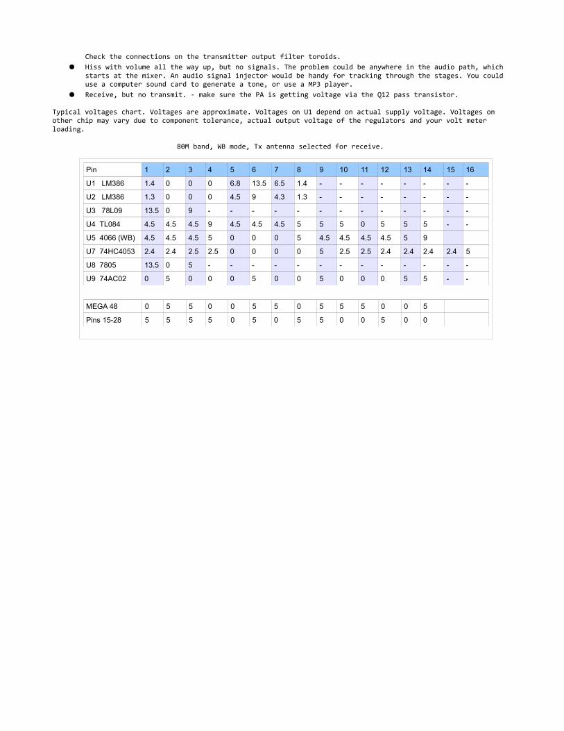
Typical voltages chart. Voltages are approximate. Voltages on U1 depend on actual supply voltage. Voltages on other chip may vary due to component tolerance, actual output voltage of the regulators and your volt meter loading.
80M band, WB mode, Tx antenna selected for receive.
Pin 1 2 3 4 5 6 7 8 9 10 11 12 13 14 15 16
U1 LM386 1.4 0 0 0 6.8 13.5 6.5 1.4 - - - - - - - -
U2 LM386 1.3 0 0 0 4.5 9 4.3 1.3 - - - - - - - -
U3 78L09 13.5 0 9 - - - - - - - - - - - - -
U4 TL084 4.5 4.5 4.5 9 4.5 4.5 4.5 5 5 5 0 5 5 5 - -
U5 4066 (WB) 4.5 4.5 4.5 5 0 0 0 5 4.5 4.5 4.5 4.5 5 9
U7 74HC4053 2.4 2.4 2.5 2.5 0 0 0 0 5 2.5 2.5 2.4 2.4 2.4 2.4 5
U8 7805 13.5 0 5 - - - - - - - - - - - - -
U9 74AC02 0 5 0 0 0 5 0 0 5 0 0 0 5 5 - -
MEGA 48 0 5 5 0 0 5 5 0 5 5 5 0 0 5
Pins 15-28 5 5 5 5 0 5 0 5 5 0 0 5 0 0

Schematics:
Receiver section:
Transmitter and control sections:

Board track layout:
Ground plane not shown for clarity. Most “floating” pads are connected to ground plane.
Transmitter filter values for other bands. Note, these use toroids of a different size then those supplied with the kit.
Value
40M 30M 20M 17M
C47 or C48 68 pfd 47 pfd 22 pfd 15 pfd
C44 or C46 330 pfd (331) 220 pfd 150 47 pfd
C49 or C51 680 pfd (681) 560 pfd 330 220 pfd
C45 or C43 330 pfd (331) 220 pfd 150 100 pfd
L2 or L4 18 turns T37-2 13 turns T37-2 13 turns T37-6 13 turns T37-6
L3 or L5 20 turns T37-2 17 turns T37-2 16 turns T37-6 16 turns T37-6