PUMA SMX series - Dormac CNC Solutions...PUMA SMX series, Doosan’s next generation Multi-tasking...
44
PUMA SMX series PUMA SMX2600 PUMA SMX3100 / L PUMA SMX2600S / ST PUMA SMX3100S / ST / LS PUMA SMX series Super Multi-tasking Turning Center
Transcript of PUMA SMX series - Dormac CNC Solutions...PUMA SMX series, Doosan’s next generation Multi-tasking...

PUMA SMX seriesPUMA SMX2600 PUMA SMX3100 / L PUMA SMX2600S / STPUMA SMX3100S / ST / LS
PUMA SMX seriesSuper Multi-tasking Turning Center

PUMA SMX series, Doosan’s next generation Multi-tasking Turning Center, features high productivity, highprecision and easy operation. By integrating the capabilities of multiple machines into one system, the PUMA SMXseries provides best in class machining capability by using multi-tasking functions which minimize the machiningtime and the number of machining operations. The PUMA SMX series also provides excellent performance for highprecision machining by minimizing thermal deformation and applying an accuracy control feature based on multiplethermal compensation functions. Ergonomic design considering operator convenience and efficient maintenanceprovides an optimal solution that meets the customer’s needs.
PUMA SMX series
0302 /
PUMA
SMX
series
Product Overview
Basic information
Basic Structure
Main Units
Machine
Performance
CUFOS
Detailed
Information
Options
Diagrams
Specifications
Customer Support
Service

* This image contains several options.
Higher Productivity through Powerful Multi-tasking FunctionsDecreases the total processing time and number of machining operations by using a single setup. This provides excellent high speed performance for component manufacturing processes which require accurate and complex machining.
Complex machining capabilities of left spindle, right spindle, B-axis , milling spindle and lower turret
High-rigidity machine construction using structural analysis design
Maximized Y-axis machining area through orthogonal design structure
Maximize productivity through simultaneous machining
Enhanced Precision through High Accuracy Control FunctionsMaintains excellent precision during long-term machining processes by minimizing the thermal deformation of the spindle and the feed axis, and maximises precision through the 0.0001° axis resolution control function.
Minimized thermal deformation of the spindle and feed axis using oil cooler
Adoption of Roller LM Guideways with high-rigidity and high precision
Equipped with 0.0001° B-axis and C-axis accuracy control function
Easy and Convenient Operation through an Ergonomic DesignFeatures excellent maintenance as well as usability and convenience through customized functions.
Front located tool magazine
Side-to-side movable swiveling operation panel with adjustable height
Convenient ATC - MAGAZINE operation panel
Contents
02 Product Overview
Basic information
04 Basic structure and cooling Concept
05 Main Units
10 Machine Performance
16 CUFOS
Detailed Information
21 Standard / Optional Specifications
24 Diagrams
35 Machine / CNC Specifications
42 Customer Support Service
0302 /

Heavy-duty, high precision
roller type LM guideways
➊ Right spindle (Servo tail stock is not applicable)
Travel
PUMA SMX2600/S,
3100/S
PUMA SMX3100L/LS
PUMA SMX 2600ST
/ 3100ST
X-axis 630 mm (24.8 inch)695 mm
(27.4 inch)
Y-axis 300 (±150) mm (11.8 (±5.9) inch)
Z-axis 1585 mm
(62.4 inch)2585 mm
(101.8 inch)1585 mm
(62.4 inch)
A-axis
1605 mm (63.2 inch)➊
1562 mm (61.5 inch)➋
2500 mm (98.4 inch)➊➋
1538 mm(60.6 inch)➊
B-axis 240 (±120) deg.
X2-axis -235 mm
(9.3 inch)
Z2-axis -1540 mm
(60.6 inch)
Rapid traverse rate
PUMA SMX2600/S,
3100/S
PUMA SMX2600ST
/ 3100ST
PUMA SMX3100L/LS
X-axis 48 m/min (1889.8 ipm)
Y-axis 36 m/min (1417.3 ipm)
Z-axis 48 m/min (1889.8 ipm)30 m/min
(1181.1 ipm)
A-axis 30 m/min
(1181.1 ipm)➊20 m/min
(787.4 ipm)➊
B-axis 40 r/min
X2-axis -24 m/min
(944.9 ipm)-
Z2-axis -36 m/min
(1417.3 ipm)-
➊ Right spindle ➋ Servo tail stock
Z-axis
Z-axis
B-axis
Y-axis X2-axis
Z2-axis A-axis
C1-axis C2-axis
Highly Rigid Design. All units are located on the main frame vertically for high rigidity.
Basic Structure Robust DesignFEM (Finite Element Method) analysis results in superior machine stability. All guideways are sealed with a protective covers, preventing high temperature chips and coolant from contacting the guideways, thus maintaining unsurpassed long-term accuracy.
Feed AxisExtended axis travel distance and improved rapid traverse rate improve workpiece machining and provide excellent productivity. The X, Y and Z-axis move orthogonally to reflect high precision machine accuracy into machining accuracy.
High Precision Roller type LM GuidewaysSP class roller type LM guideways for extra load capacity and rigidity are used on all axes to enable high rapid traverse rates.
0504 /
PUMA
SMX
series
Product Overview
Basic information
Basic Structure
Main Units
Machine
Performance
CUFOS
Detailed
Information
Options
Diagrams
Specifications
Customer Support
Service

Material Aluminium
Tool Diamond tool (Nose radius 0.5 min (0.02 in.))
Spindle speed 3000 r/min
Feedrate 0.5 mm/rev (0.02 ipr)
Material Aluminium
Tool End mill Ø20 mm (0.787 in.)
Spindle speed 8000 r/min
Feedrate 2500 mm/min (98.4 ipm)
0.5µm 3.2µm
* This test is performed under Doosan Machine Tool’s test environment.
270°
90°
180° 0°
270°
90°
180° 0°
Structural preparation to minimize thermal error and ensure superior accuracy for a long time operation
Basic Cooling Concept for Higher Accuracyin a Long time Machining
Minimization of Thermal Deformation by Oil CoolingSpindle and ball screw core cooling system minimizes thermal deformation during long machining processes and enhances high accuracy performance.
Cooling Oil
in
out
Milling spindle
cooling
Left and right spindle and
headstock base cooling
Ball screw core cooling system
X1-axis standard, Y-axis and Z-axis are optional
Cutting AccuracyBy performing extended test procedures of individual machine elements and detailed analysis of results, the SMX series achieves a high level of precision and reliability that fulfills customer satisfaction.
Turning (O.D. machining)
PUMA SMX2600
Milling (X-Y plane)
PUMA SMX2600
0504 /
Model SpindleStandard
Chuck (inch)
Spindle speed(r/min)
PowerkW (Hp)
TorqueN·m (ft-lbs)
Condition
PUMA SMX2600 seriesLeft
Spindle
10 400026 / 22
(34.9 / 29.5)700
(516.6)*30min/cont.
PUMA SMX3100 series 12 300030 / 25
(40.2 / 33.5)1203
(887.8)30min/cont.
PUMA SMX2600S/3100S/ 3100LS Right
Spindle10 4000
26 / 22(34.9 / 29.5)
700(516.6)*
30min/cont.PUMA SMX2600ST/ 3100ST
621(458.3)*
Model SpindleTool
shankSpindle speed
(r/min)Power
kW (Hp)Torque
N·m (ft-lbs)Condition
PUMA SMX2600 seriesMilling Spindle
CAPTO C6 12000
26 / 18.5 / 15
(34.9 / 24.8 / 20.1)
124 (91.5)*2.5min /
10min / cont.PUMA SMX3100 series
* On S3 25% operation
* On S3 25% operation
PUMA SMX2600/3100S seriesRight Spindle (on only S/LS/ST models)
PUMA SMX3100 seriesLeft Spindle
Perfect combination of3 key spindles to ensure machining stability under various cutting conditions.
Spindle Perfect combination of key- rotation axisBoth left and right spindle are capable of high accuracy C-axis control and perform variousmachining functions like turning, milling and synchronized cutting using single set-up with milling spindle.
12000 r/min
26 kW (34.9 Hp)
Milling Spindle
CAPTO C6Tool shank of Milling Spindle
option HSK –A63
option 8000 r/min
10inch optional 12 inch12inch optional 15 inch
0706 /
PUMA
SMX
series
Product Overview
Basic information
Basic Structure
Main Units
Machine
Performance
CUFOS
Detailed
Information
Options
Diagrams
Specifications
Customer Support
Service

ModelTail stock
travelmm (inch)
Max. quill thrust force
kN (lbs)
Tail stock center
PUMA SMX2600 / 3100
1562(61.5)
10 (2248.0)
Built-in type Dead center,
MT#5PUMA SMX3100L
2500(98.4)
15 (3374.4)
B-axis positioning control Precise continuous index
B-axis index that can have swivel
positioning of every 0.0001˚ in ±120 ˚
performs not only horizontal front face
machining but also angular machining.
B-axis 240° ( 120° )
-120° +120°
Large B-axis Stroke
High Precision Control of Spindle axes (C & B-axis)Machining operation is mainly done by Left and Milling spindle. C-axis of left spindle and B-axis of milling spindle with Y-axis control realize multi-tasking turning center that can drill, tap and end mill in any angle and also deliver the ability to cut precise angles and sculpted contours(5-axis simultaneous controlled specification is option).
C-axis positioning control
To enhance C-axis positioning
accuracy of left spindle,
the position compensation
sensor has been adopted.
Left spindle can have
C-axis positioning control
of every 0.0001˚ in 360˚.
0.0001°Left spindle
Note) C-axis of Right spindle : 0.001˚
Swivel and index ing of B-axis is by servo motor and roller gear cam
with high-rigidity and high-precision
Dual pressure braking
Depends on cutting condition, braking index of B-axis
can be controlled.
Braking index at a random angle
Within its swivel ±120 ˚, B-axis can be indexed and braked
precisely at a random angle.
Servo driven tailstockServo tailstock make part set-up faster and easier. The operator inputs the proper M-code information in the control and tailstocks move to its proper positions automatically by linear motion control of servo motor and ball screw. No manual adjustments are required. More easier and faster
set-up of the tailstock using M-code program by servo motor and ball screw
Tailstock
0706 /

ATC
Monitoring ATC internal status
The internal operation status of the
ATC can be photographed by the
camera and displayed on the screen .
10.4 inch
3.5 inch
40 tools
Tool storage
Max. tool length (from gauge line) 450 mm (17.7 inch)
Max. tool weight 12 kg (26.5 lb)
Max. tool moment 9.8 N·m (7.2 ft-lbs)
Max. tool diameter (continuous) 90 mm (3.5 inch)
Max. tool diameter (adjacent pots are empty) 130 mm (5.1inch)
Front located tool magazine ensuring easy
tool maintenance
The photo is
tool magazine of 80 tools
*120Tools ATC option is only available to PUMA SMX2600ST/3100ST.
Servo ATC and Servo tool magazine ensuring fast and reliable tool indexing
Automatic Tool Changer
Servo driven ATC & Tool magazineThe tool magazine can be increased up to 120 tools and tools are selected by a fixed address method that follows the shorter path.
80 / 120 tools*
ATC-MAGAZINE Operation Panel The status of ATC and the tool magazine unit are identified visually by using a graphic touch panel display and touch operation. The touch screen also operates the ATC, the tool magazine and the tool feed pot carrier individually.
Enlarged touch screen panel is available as an option
10.4inchoption 3.5 inch
10.4 inch
Tool information display
Improves the tool management by
saving and displaying useful tool
related information.
Display and touch operation
Displays ATC – MAGAZINE related
information and supports manual
operation by touchscreen. 7.5-
inch large screen specification is
available for the ATC – MAGAZINE
operation panel.
0908 /
PUMA
SMX
series
Product Overview
Basic information
Basic Structure
Main Units
Machine
Performance
CUFOS
Detailed
Information
Options
Diagrams
Specifications
Customer Support
Service
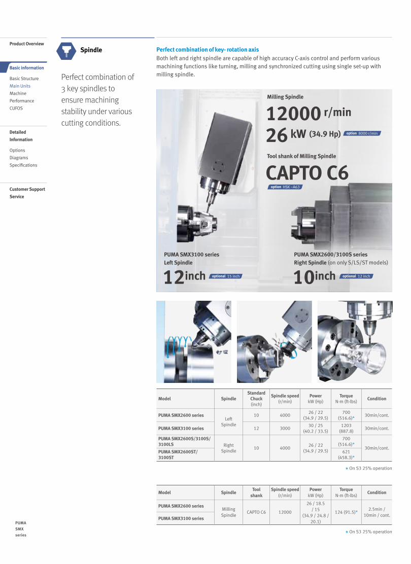
PUMA SMX3100L/LS can accommodate workpieces as long as 2540mm between
centers. The machine can process long tube such as landing gear axle requiring the
center bore. Because the Automatic tool changer on this model cannot handle long
boring bar, the separate tool magazine just for these tools can has 3 tool stations for
tools as long as max. 600mm 3tools➊
Tool storage
Ø 30 x L 800 mm➋
Max. Tool size
Ø 60 x L 600mm
Max. Tool size
15kg
Max. Weight
15kg
Max. Weight
or
➊ You can select tools storage capacity 2+1 tools instead of 3 tools. The 2+1
tools storage means 2 tools of Ø60
x L600 mm or Ø30 x L800 mm and 1 large diameter tools, Ø190 x L200
mm can be mounted in long boring
bar magazine.➋ Ø30 x L800 mm sized tool is not Long
boring bar but Gun drill. We do not
recommend long boring bar sized
Ø30 x L800 mm.
Strong and rigid lower turret in multi-taskingis to provide morepowerful manufacturingperformance and a variety of new applications.
Turret
Tool holder type
BMT 65P
Number of Tool stations
12 ea
Max. Rotary Tool Speed
5000 r/min
High rigid servo driven Lower turret (only on PUMA SMX2600ST / 3100ST )
Turret rotation, acceleration/deceleration and large diameter curvic coupling are controlled by a high-torque servo motor. Unclamp and rotation are virtually simultaneous. The fast index response keeps cycle times short.
Various applications of lower turret
Case1) Steady rest on lower turret Case2) Tailstock on lower turret Application for long part machining
As option just for PUMA SMX3100L/LS, long boring bar magazine is available to ensure more easy application to long tube machining
AdditionalTool Magazine
Tools magazine for Long boring bar option for PUMA SMX3100L / LS
PUMA SMX3100L/LS can be equipped with long boring bar magazine as option.
(Ø 2.4 x L 23.6 inch)
(Ø 2.4 x L 31.5 inch)
(33.1 lb)
(33.1 lb)
0908 /
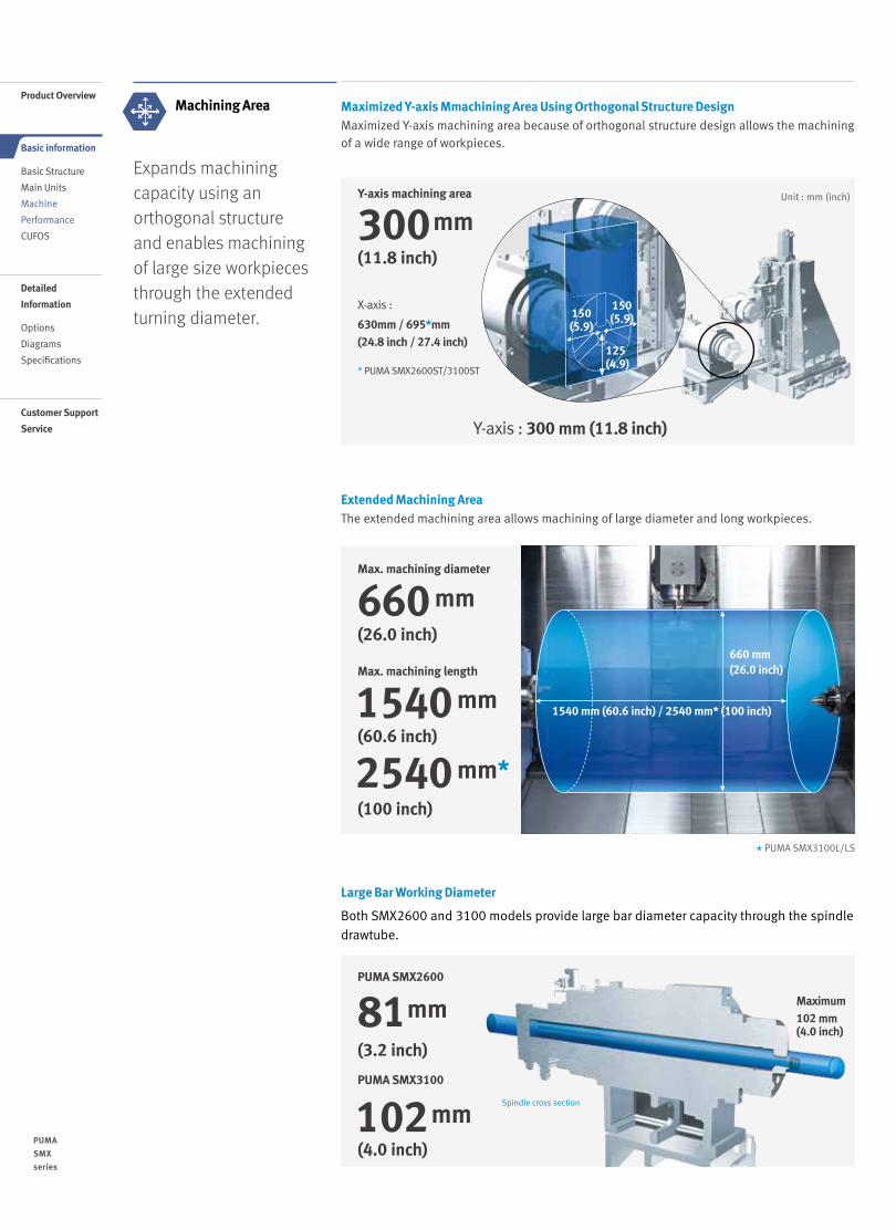
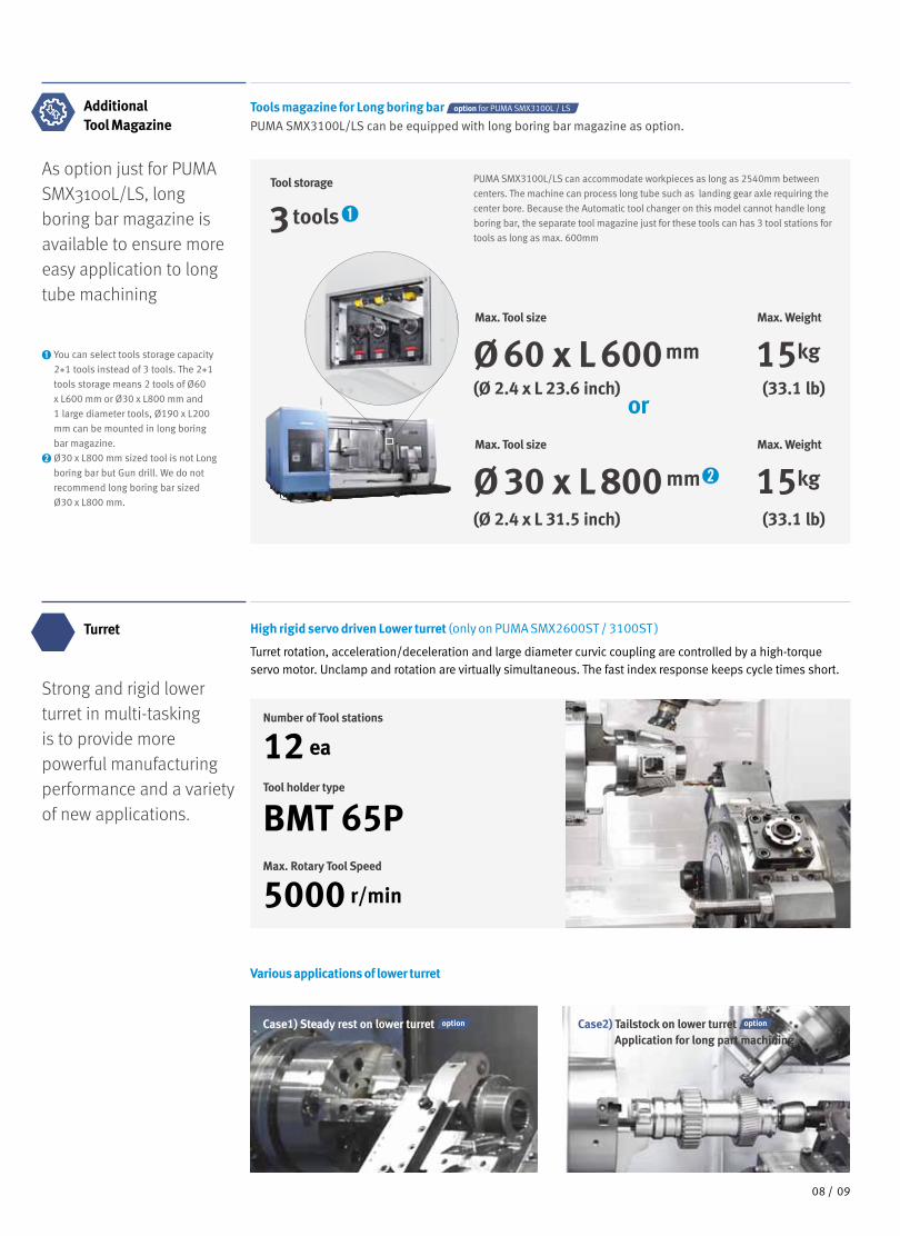
Large Bar Working Diameter
Both SMX2600 and 3100 models provide large bar diameter capacity through the spindledrawtube.
Maximum 102 mm(4.0 inch)
Spindle cross section
81mmPUMA SMX2600
102mm
PUMA SMX3100
660 mm (26.0 inch)
1540 mm (60.6 inch) / 2540 mm* (100 inch)
* PUMA SMX3100L/LS
Expands machining capacity using an orthogonal structure and enables machining of large size workpieces through the extended turning diameter.
Machining Area Maximized Y-axis Mmachining Area Using Orthogonal Structure DesignMaximized Y-axis machining area because of orthogonal structure design allows the machining of a wide range of workpieces.
X-axis :
630mm / 695*mm(24.8 inch / 27.4 inch)
* PUMA SMX2600ST/3100ST
300mm(11.8 inch)
Y-axis machining area
Y-axis : 300 mm (11.8 inch)
125 (4.9)
150(5.9)
150(5.9)
Unit : mm (inch)
Extended Machining AreaThe extended machining area allows machining of large diameter and long workpieces.
660 mm(26.0 inch)
Max. machining diameter
1540 mm(60.6 inch)
Max. machining length
2540 mm*(100 inch)
(3.2 inch)
(4.0 inch)
1110 /
PUMA
SMX
series
Product Overview
Basic information
Basic Structure
Main Units
Machine
Performance
CUFOS
Detailed
Information
Options
Diagrams
Specifications
Customer Support
Service

O.D. cutting (PUMA SMX3100)
U-drill (milling)
Face milling
End milling
Tapping
* The results, indicated in this catalogue are provides as example. They may not be obtained due todifferences in cutting conditions and environmental conditions during measurement.
Higher Productivity by Multi-tasking performanceFaster machining time compared to many conventional machines provides superior productivity andmachining capability.
Tool mm (inch)
Milling spindle speedr/min
Feedratemm/min (ipm)
Material removal ratecm3/min (inch3/min)
Ø63 (2.5) 1010 131 (5.2) 409 (25.0)
Tool mm (inch)
Milling spindle speedr/min
Feedratemm/min (ipm)
M30 x P3.5 (M1.2 x P0.1) 212 742 (29.2)
Tool mm (inch)
Milling spindle speedr/min
Radial cutting depthmm (inch)
Feedratemm/min (ipm)
Material removal ratecm3/min (inch3/min)
Ø25 (1.0) 382 25 (1.0) 200 (7.9) 125 (7.6)
Spindle speedr/min
Cutting speedm/min (ipm)
Feedratemm/rev (ipr)
Radial cutting depthmm (inch)
Material removal ratecm3/min (inch3/min)
253210
(8267.7)0.55
(0.022)8.5
(0.3)1405(85.7)
Tool mm (inch)
Milling spindle speedr/min
Radial cutting depthmm (inch)
Feedratemm/min (ipm)
Material removal ratecm3/min (inch3/min)
Ø80 (3.1) 1100 5 (0.2) 1117 (44.0) 357 (21.8)
Increased work efficiency using one time setup on one machine
163 Minutes
-Setting
-Turning
-Turning
-Milling
-Milling
-Automatic feed
SMX2600S-Setting-Turning
-Remove and move workpiece
-Remove and move workpiece
-Setting
-Setting
-Conventional Milling
-Change fixture for the angular surface machining
-Milling for the angular surface
-Turning
650 Minutes
Machine 1(Turning Center)
Machine 3(Turning Center)
Machine 2(Machining Center)
Conventional machining
Multi-tasking of PUMA SMX
Powerful Multi-tasking
Higher Efficiency
Powerful machining capability in various operation such as turning, milling and drill and tapping and multi-tasking performance ensuring more higher machining efficiency.
Cutting Performance
Powerful Machining
75%
Reduced production lead time by
1110 /

Three machines One machine
Three operators One operator
Benefits of Multi-tasking operationUsing a single set up, one machine is capable of performing all machining processes that generally require two three or even more machines. By minimizing time and labor, the process cost is reduced and lead times are shortened by up to 75%. This provides a significant advantage when manufacturing small batches of a variety of products.
Multitasking, which is performing more than one duty at once, This can lead to as much as a 40 percent increase in productivity and can positively impact your company's bottom line.
Reduced time and operator requirements and enhanced accuracy!
Conventional machining process PUMA SMX process
75%
Reduced production lead time by
Application Performance
Floor space for only one machineFloor space for at least three machines required
One machine setupMove
workpieceMove
workpieceOne
machine setup Another
machine setupAnother
machine setup
Providing 5-axis Complex Machining Capabilities (Standard when applying FANUC 31i-5)
Simultaneous 5-axis machining functions such as TCP* are built-in, thereby making the machining of complex shapes easier, such as an automotive engine impeller or an aero engine blade.
Tool Center Point Control- Facilitating the high precision machining of
the surface by automatic control of tool path
- Decreasing the time for the machining setup
and the cutting process
Ball-end mill
Cutting point (programmed)
Radius-end mill Square-end mill
Cutting point command - Increasing the productivity by automatically compensating
when using various tool tips without changing the machining
program
- Performing effective tool correction
* TCP : Tool Center Point
Program
Real tool move
1312 /
PUMA
SMX
series
Product Overview
Basic information
Basic Structure
Main Units
Machine
Performance
CUFOS
Detailed
Information
Options
Diagrams
Specifications
Customer Support
Service
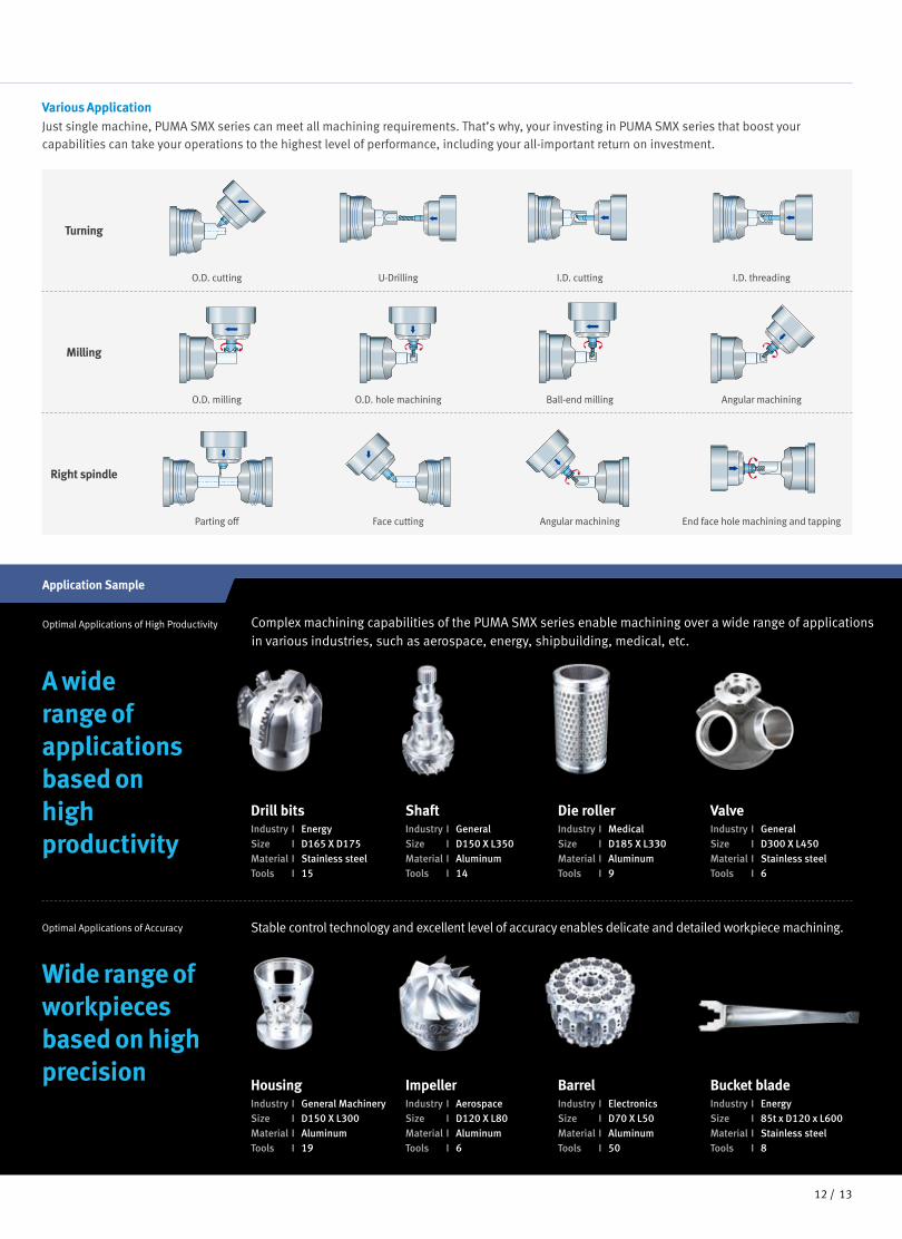
Optimal Applications of Accuracy
Optimal Applications of High Productivity Complex machining capabilities of the PUMA SMX series enable machining over a wide range of applications in various industries, such as aerospace, energy, shipbuilding, medical, etc.
Application Sample
Right spindle
Parting off Face cutting Angular machining End face hole machining and tapping
Milling
O.D. milling O.D. hole machining Ball-end milling Angular machining
Turning
O.D. cutting U-Drilling I.D. cutting I.D. threading
Various ApplicationJust single machine, PUMA SMX series can meet all machining requirements. That’s why, your investing in PUMA SMX series that boost your capabilities can take your operations to the highest level of performance, including your all-important return on investment.
Wide range of workpieces based on high precision
HousingIndustry I General MachinerySize I D150 X L300Material I AluminumTools I 19
ImpellerIndustry I AerospaceSize I D120 X L80Material I AluminumTools I 6
BarrelIndustry I ElectronicsSize I D70 X L50Material I AluminumTools I 50
Bucket bladeIndustry I EnergySize I 85t x D120 x L600Material I Stainless steelTools I 8
Stable control technology and excellent level of accuracy enables delicate and detailed workpiece machining.
A wide range of applications based on high productivity
Drill bitsIndustry I EnergySize I D165 X D175Material I Stainless steelTools I 15
ShaftIndustry I General Size I D150 X L350Material I AluminumTools I 14
Die rollerIndustry I MedicalSize I D185 X L330Material I AluminumTools I 9
ValveIndustry I GeneralSize I D300 X L450Material I Stainless steelTools I 6
1312 /
1
4
3
2
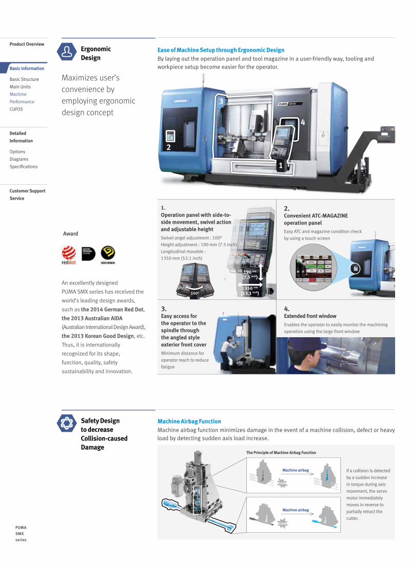
3.Easy access for the operator to the spindle through the angled style exterior front cover
Minimum distance for
operator reach to reduce
fatigue
4.Extended front window
Enables the operator to easily monitor the machining
operation using the large front window
2. Convenient ATC-MAGAZINE operation panel
Easy ATC and magazine condition check
by using a touch screen
100°
1.Operation panel with side-to- side movement, swivel action and adjustable height
Swivel angel adjustment : 100°
Height adjustment : 190 mm (7.5 inch)
Longitudinal movable : 1350 mm (53.1 inch)
Ease of Machine Setup through Ergonomic DesignBy laying out the operation panel and tool magazine in a user-friendly way, tooling and workpiece setup become easier for the operator.
Maximizes user’s convenience by employing ergonomic design concept
Ergonomic Design
An excellently designed
PUMA SMX series has received the
world’s leading design awards,
such as the 2014 German Red Dot,
the 2013 Australian AIDA
(Australian International Design Award),
the 2013 Korean Good Design, etc.
Thus, it is internationally
recognized for its shape,
function, quality, safety
sustainability and innovation.
Award
190 mm
(7.5 inch)
1350 mm
(53.1 inch)
Machine Airbag FunctionMachine airbag function minimizes damage in the event of a machine collision, defect or heavy load by detecting sudden axis load increase.
Safety Design to decrease Collision-caused Damage
If a collision is detected
by a sudden increase
in torque during axis
movement, the servo
motor immediately
moves in reverse to
partially retract the
cutter.
The Principle of Machine Airbag Function
Machine airbag
Crash
Machine airbag
Crash
1514 /
PUMA
SMX
series
Product Overview
Basic information
Basic Structure
Main Units
Machine
Performance
CUFOS
Detailed
Information
Options
Diagrams
Specifications
Customer Support
Service

Tool Load MonitoringIt is possible to display various types of information about each tool and to monitor the tool load in real-time.
Optimized system design that reflects Doosan’s know-how from long-term experience and the customer’s needs
15 inch
10.4 inch
* EOP : Easy Operation Package / NC : Numerical Control
* MTTR : Mean Time to Repair
Easy Operation and Maintenance
Enhances ease of operation by the design based on the operator’s functions and also provides maintenance functions that reduce downtime by decreasing the MTTR.*
User-friendly Operation PanelThe operator panel is designed to provide easy operation and also maintenance functions to reduce downtime. A large size 15-inch screen is applied as standard on the customized operator panel.
15-inch wide screen display unit
A design for easy operation
easy and convenient user interface, enhanced lamp visibility,
optimized button size for easy operation and long life, use of
a partition-type layout to prevent incorrect button operation
Addition of simple option buttons
additional function buttons can be easily fitted to spare sections
of the operator panel
Customized function support
attachment of customized function switches and customized
additional panel design
Simple Alarm FunctionDoosan’s EOP* system enables the user to operate the NC* system more conveniently.
Alarm Guide Function
- Alarm notification for user
check-up
Easy check-up of alarm status and troubleshooting problems by access to 3D displays of internal mechanisms
- Alarm notification of
actuator and sensor status
Periodic Maintenance Notification Function
Manages and extends the lifespan of cutting tools
- Avoids unexpected downtime
- Reduces maintenance cost
- Increases production efficiency
- Optimizes the performance
1514 /

1716 /
PUMA
SMX
series
CUFOS is a PC based control system created by Doosan Machine Tools. Equipped with intuitive user-friendly functions such as a smart phone screen and easy customization, CUFOS helps to improve operational efficiency and performance for the user.
Customized User-friendly Flexible Operating System
• Features of CUFOS
Customized
• Simple Customization
• Extend Functionality with Additional apps
• Register for up to 6 individual users
Flexible• Simple Connectivity with External Software
(Cloud, Office etc.)
• SSD data server app
• PC based operating system (Windows®7)
User-Friendly
• 19 inch Multi Touch Screen
• Multiple Apps such as –
- CPS app (Collision Protection System)
- Tool management app
- Status monitoring and alarm guidance app
• Max. storage size: SSD 128GB available
• App-based Interface for Smartphones &
Tablet PC
Product Overview
Basic information
Basic Structure
Main Units
Machine
Performance
CUFOS
Detailed
Information
Options
Diagrams
Specifications
Customer Support
Service

1716 /
User-Friendly Interface
CUFOS, the PC-based control created by Doosan Machine Tools, is an integrated system solution using an intuitive 19 inch touch screen. The system provides a convenient operator interface, a high level of customization and many useful high technology apps.
CUFOS operation for enhanced productivity
The CUFOS operating system is based upon the integration of all aspects of the manufacturing process, including setting, machining and maintenance. It consolidates up-to-date software technology created by Doosan Machine Tools, to improve overall efficiency and productivity. Using the system’s modular construction, each function can be easy integrated with external PC software systems and applications, such as CAM and Tool Data systems.
Maximizing efficiency for multi-tasking machining
Applied to those multi-tasking turning center like PUMA SMX series as well as high performance, high productivity horizontal machining center NHP/NHM series, CUFOS maximizes the operational efficiency by adding up-to-date software technology of Doosan Machine Tools including new developed application such as CPS (Collision Protection System), Turn-cut, and the Tool Management function etc.
CUFOSInterface
Programing
Set up
Tool data
Machining
MaintenanceDOOSAN CUFOS
PC software Applications
PUMA SMX series NHP series NHM series
CUFOSOpen CNC
CUFOSMachines
Supports various Apps in three fields – Setup/Machining/Utility.It provides easy configuration by allowing the user to add and edit functions on the Home Screen according to job requirements.
Intuitive operation via the touch screen
Simple customization is available for customers’ work environment.
1918 /
PUMA
SMX
series
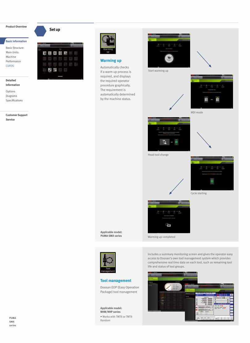
Applicable model: NHM/NHP series
• Works with TMT8 or TMT8 Random
Includes a summary monitoring screen and gives the operator easy access to Doosan’s own tool management system which provides comprehensive real time data on each tool, such as remaining tool life and status of tool groups.
Applicable model: PUMA SMX series
Warming up
Automatically checks if a warm up process is required, and displays the required operator procedure graphically. The requirement is automatically determined by the machine status.
Tool management
Doosan EOP (Easy Operation Package) tool management
Warming up completed
Product Overview
Basic information
Basic Structure
Main Units
Machine
Performance
CUFOS
Detailed
Information
Options
Diagrams
Specifications
Customer Support
Service
Set up
Start warming up
MDI mode
Cycle starting
Head tool change
1918 /
Machining
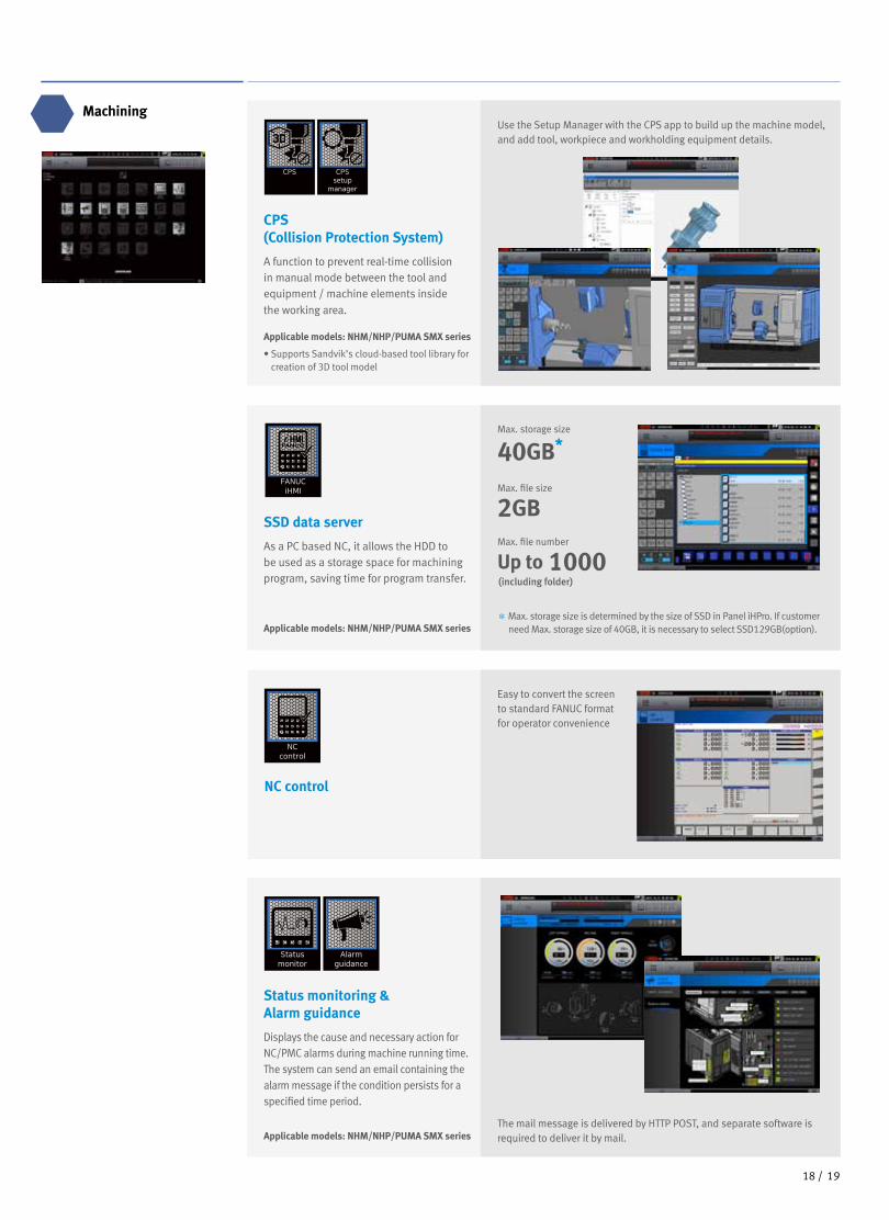
Applicable models: NHM/NHP/PUMA SMX series
• Supports Sandvik’s cloud-based tool library for creation of 3D tool model
Use the Setup Manager with the CPS app to build up the machine model, and add tool, workpiece and workholding equipment details.
CPS (Collision Protection System)
A function to prevent real-time collision in manual mode between the tool and equipment / machine elements inside the working area.
The mail message is delivered by HTTP POST, and separate software is required to deliver it by mail.
Easy to convert the screen to standard FANUC format for operator convenience
Applicable models: NHM/NHP/PUMA SMX series
Status monitoring & Alarm guidance
Displays the cause and necessary action for NC/PMC alarms during machine running time. The system can send an email containing the alarm message if the condition persists for a specified time period.
NC control
Applicable models: NHM/NHP/PUMA SMX series* Max. storage size is determined by the size of SSD in Panel iHPro. If customer
need Max. storage size of 40GB, it is necessary to select SSD129GB(option).
SSD data server
As a PC based NC, it allows the HDD to be used as a storage space for machining program, saving time for program transfer.
Max. storage size
40GB*
Max. file size
2GBMax. file number
(including folder)
Up to 1000
2120 /
PUMA
SMX
series
Product Overview
Basic information
Basic Structure
Main Units
Machine
Performance
CUFOS
Detailed
Information
Options
Diagrams
Specifications
Customer Support
Service
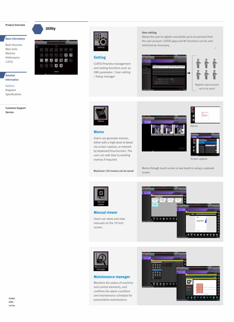
Utility
Maximum 120 memos can be saved
Setting
CUFOS Provides management and setting functions such as HMI parameter / User setting / Setup manager
Memo
Users can generate memos, either with a high level of detail via screen capture, or entered by keyboard/touchscreen. The user can add data to existing
memos if required
Maintenance manager
Monitors the status of machine and control elements, and confirms the alarm condition and maintenance schedule for preventative maintenance.
Manual viewer
Users can store and view manuals on the 19 inch screen.
Memo through touch screen or key board or using a captured
screen
Register user account
up to six users
Memo
Screen capture
User settingAllows the user to register and delete up to six persons from
the user account. CUFOS apps and NC functions can be user-
restricted as necessary.
2120 /
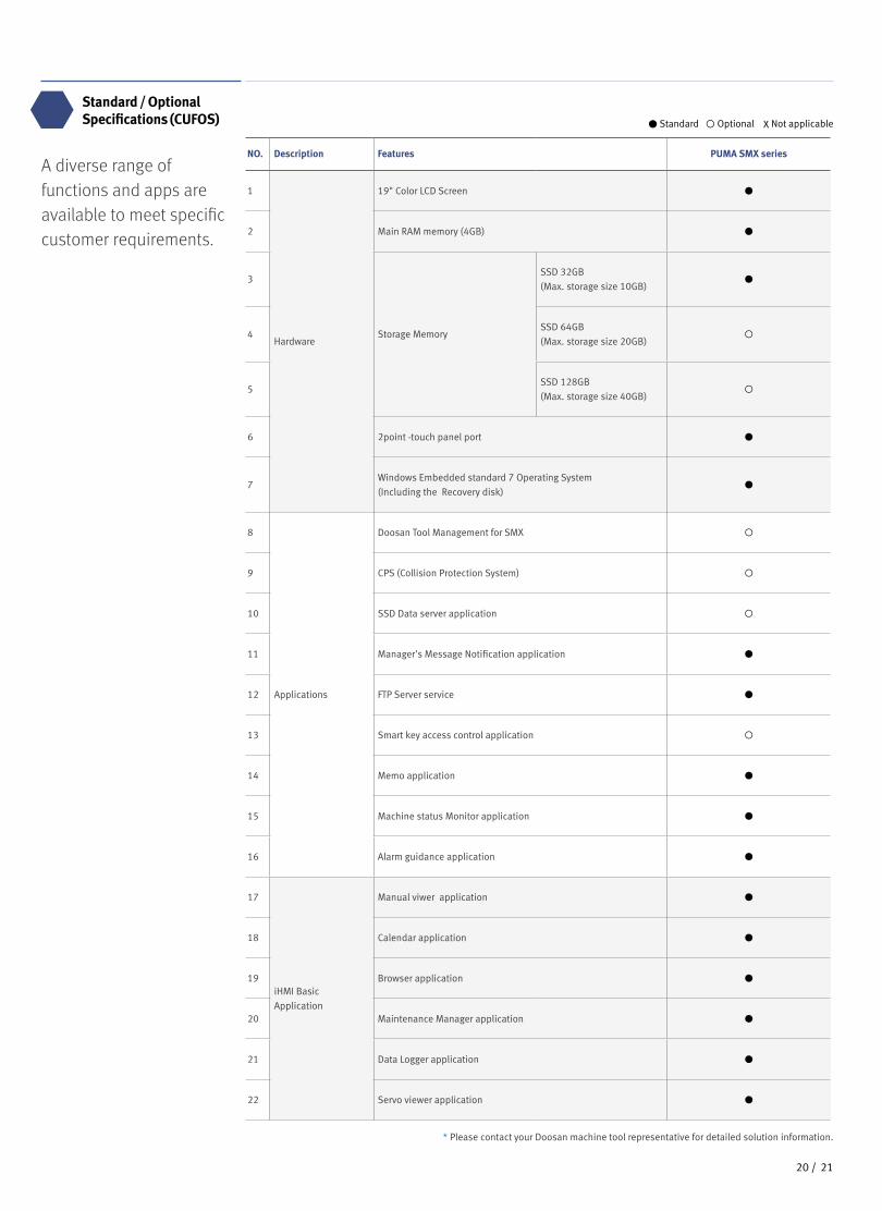
A diverse range of functions and apps are available to meet specific customer requirements.
Standard / OptionalSpecifications (CUFOS)
NO. Description Features PUMA SMX series
1
Hardware
19" Color LCD Screen
2 Main RAM memory (4GB)
3
Storage Memory
SSD 32GB
(Max. storage size 10GB)
4SSD 64GB
(Max. storage size 20GB)
5SSD 128GB
(Max. storage size 40GB)
6 2point -touch panel port
7Windows Embedded standard 7 Operating System
(Including the Recovery disk)
8
Applications
Doosan Tool Management for SMX
9 CPS (Collision Protection System)
10 SSD Data server application
11 Manager's Message Notification application
12 FTP Server service
13 Smart key access control application
14 Memo application
15 Machine status Monitor application
16 Alarm guidance application
17
iHMI Basic
Application
Manual viwer application
18 Calendar application
19 Browser application
20 Maintenance Manager application
21 Data Logger application
22 Servo viewer application
● Standard ◦ Optional X Not applicable
* Please contact your Doosan machine tool representative for detailed solution information.
● Standard ◦ Optional X Not applicable
2322 /
PUMA
SMX
series
NO. Division OptionPUMA SMX 2600
PUMA SMX 3100
PUMA SMX
3100L
PUMA SMX
2600S
PUMA SMX
3100S
PUMA SMX
3100LS
PUMA SMX
2600ST
PUMA SMX
3100ST
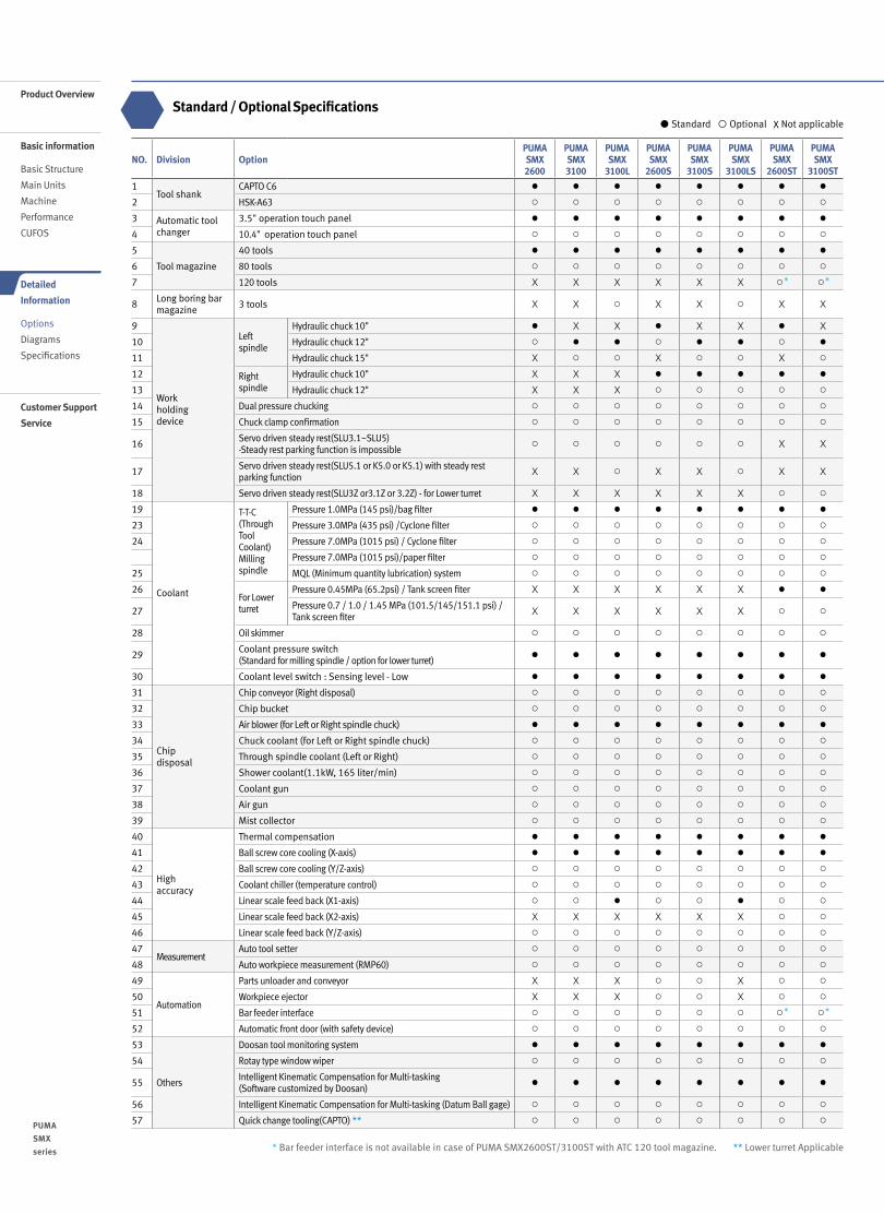
1Tool shank
CAPTO C6 ● ● ● ● ● ● ● ●
2 HSK-A63 ○ ○ ○ ○ ○ ○ ○ ○
3 Automatic tool changer
3.5" operation touch panel ● ● ● ● ● ● ● ●
4 10.4" operation touch panel ○ ○ ○ ○ ○ ○ ○ ○
5
Tool magazine
40 tools ● ● ● ● ● ● ● ●
6 80 tools ○ ○ ○ ○ ○ ○ ○ ○
7 120 tools X X X X X X ○* ○*
8 Long boring bar magazine
3 tools X X ○ X X ○ X X
9
Work holding device
Left spindle
Hydraulic chuck 10" ● X X ● X X ● X
10 Hydraulic chuck 12" ○ ● ● ○ ● ● ○ ●
11 Hydraulic chuck 15" X ○ ○ X ○ ○ X ○
12 Right spindle
Hydraulic chuck 10" X X X ● ● ● ● ●
13 Hydraulic chuck 12" X X X ○ ○ ○ ○ ○
14 Dual pressure chucking ○ ○ ○ ○ ○ ○ ○ ○
15 Chuck clamp confirmation ○ ○ ○ ○ ○ ○ ○ ○
16 Servo driven steady rest(SLU3.1~SLU5)-Steady rest parking function is impossible
○ ○ ○ ○ ○ ○ X X
17 Servo driven steady rest(SLU5.1 or K5.0 or K5.1) with steady rest parking function
X X ○ X X ○ X X
18 Servo driven steady rest(SLU3Z or3.1Z or 3.2Z) - for Lower turret X X X X X X ○ ○
19
Coolant
T-T-C(ThroughToolCoolant)Millingspindle
Pressure 1.0MPa (145 psi)/bag filter ● ● ● ● ● ● ● ●
23 Pressure 3.0MPa (435 psi) /Cyclone filter ○ ○ ○ ○ ○ ○ ○ ○
24 Pressure 7.0MPa (1015 psi) / Cyclone filter ○ ○ ○ ○ ○ ○ ○ ○
Pressure 7.0MPa (1015 psi)/paper filter ○ ○ ○ ○ ○ ○ ○ ○
25 MQL (Minimum quantity lubrication) system ○ ○ ○ ○ ○ ○ ○ ○
26For Lower turret
Pressure 0.45MPa (65.2psi) / Tank screen fiter X X X X X X ● ●
27 Pressure 0.7 / 1.0 / 1.45 MPa (101.5/145/151.1 psi) / Tank screen fiter
X X X X X X ○ ○
28 Oil skimmer ○ ○ ○ ○ ○ ○ ○ ○
29 Coolant pressure switch (Standard for milling spindle / option for lower turret)
● ● ● ● ● ● ● ●
30 Coolant level switch : Sensing level - Low ● ● ● ● ● ● ● ●
31
Chip disposal
Chip conveyor (Right disposal) ○ ○ ○ ○ ○ ○ ○ ○
32 Chip bucket ○ ○ ○ ○ ○ ○ ○ ○
33 Air blower (for Left or Right spindle chuck) ● ● ● ● ● ● ● ●
34 Chuck coolant (for Left or Right spindle chuck) ○ ○ ○ ○ ○ ○ ○ ○
35 Through spindle coolant (Left or Right) ○ ○ ○ ○ ○ ○ ○ ○
36 Shower coolant(1.1kW, 165 liter/min) ○ ○ ○ ○ ○ ○ ○ ○
37 Coolant gun ○ ○ ○ ○ ○ ○ ○ ○
38 Air gun ○ ○ ○ ○ ○ ○ ○ ○
39 Mist collector ○ ○ ○ ○ ○ ○ ○ ○
40
High accuracy
Thermal compensation ● ● ● ● ● ● ● ●
41 Ball screw core cooling (X-axis) ● ● ● ● ● ● ● ●
42 Ball screw core cooling (Y/Z-axis) ○ ○ ○ ○ ○ ○ ○ ○
43 Coolant chiller (temperature control) ○ ○ ○ ○ ○ ○ ○ ○
44 Linear scale feed back (X1-axis) ○ ○ ● ○ ○ ● ○ ○
45 Linear scale feed back (X2-axis) X X X X X X ○ ○
46 Linear scale feed back (Y/Z-axis) ○ ○ ○ ○ ○ ○ ○ ○
47Measurement
Auto tool setter ○ ○ ○ ○ ○ ○ ○ ○
48 Auto workpiece measurement (RMP60) ○ ○ ○ ○ ○ ○ ○ ○
49
Automation
Parts unloader and conveyor X X X ○ ○ X ○ ○
50 Workpiece ejector X X X ○ ○ X ○ ○
51 Bar feeder interface ○ ○ ○ ○ ○ ○ ○* ○*
52 Automatic front door (with safety device) ○ ○ ○ ○ ○ ○ ○ ○
53
Others
Doosan tool monitoring system ● ● ● ● ● ● ● ●
54 Rotay type window wiper ○ ○ ○ ○ ○ ○ ○ ○
55 Intelligent Kinematic Compensation for Multi-tasking(Software customized by Doosan)
● ● ● ● ● ● ● ●
56 Intelligent Kinematic Compensation for Multi-tasking (Datum Ball gage) ○ ○ ○ ○ ○ ○ ○ ○
57 Quick change tooling(CAPTO) ** ○ ○ ○ ○ ○ ○ ○ ○
Product Overview
Basic information
Basic Structure
Main Units
Machine
Performance
CUFOS
Detailed
Information
Options
Diagrams
Specifications
Customer Support
Service
Standard / Optional Specifications
* Bar feeder interface is not available in case of PUMA SMX2600ST/3100ST with ATC 120 tool magazine. ** Lower turret Applicable

Optional Equipment for Automation
49, 50, 51
Various peripheral equipment is available to support the SMX to improve its performance and productivity.
Chip Conveyor (Right side exit) 31
The conveyor provides a superior chip removal system and is designed with a stable structure for easy maintenance and reduced leakage. By selecting the correct type of conveyor, the efficiencyof the machine working area is increased.
Coolant Chiller (Recommendation) 43
A coolant chiller minimizes the thermal deformation by controlling the temperature of the return coolant to the machine, thus improving the accuracy.
Coolant chiller
Coolant tank
Name Hinge Belt Magnetic ScraperDrum filter +Hinge scraper (Double type)
Application For steel For castings For steel, castings, nonferrous metal
Features
- General- Appropriate for a heavy material
chip of more than 30 mm in length
- Easy maintenance- Eject the chip by scraping and
raising the chip with the scraper
- Appropriate for both a long and a short chip - Filtering coolant
Shape
Servo driven Steady rest 16, 17, 18
This equipment supports long workpieces during the machining process. Linear positioning of the steady rest is achieved by servo motor and ball screw and can be positioned during cycle.
Steady rest parking function*
When you don’t want to use steady rest, you can
make it parked under left chuck.
* This function is possible just for PUMA SMX3100L/LS
with the steady rest selected one from among SLU5.1,
K5.0 and K5.1.
- Bar feeder interface- Parts unloader and conveyor- Workpiece ejector
➊ In PUMA SMX2600/S, 3100/S, the steady rest parking function is not possible. And also, the function is not possible
when the steady rest is selected from among SLU-3.1 to SLU-5 for PUMA SMX3100L/LS.➋ Using 15-inch chuck in PUMA SMX3100L/LS instead of standard 12-inch, if you select Servo driven Steady rest for
PUMA SMX3100L/LS, the steady rest must be K5.1 to make it use of steady rest parking function.
Applicable model Steady rest Working range
PUMA SMX2600 / S PUMA SMX3100/L/S/LS(Steady rest parking function is impossible) ➊
SLU-3.1 Ø20~Ø165 mm (0.8~6.5 inch)
SLU-3.2 Ø50~Ø200 mm (2.0~7.9 inch)
SLU-4 Ø35~Ø245 mm (1.4~9.6 inch)
SLU-5 Ø50~Ø310 mm (2.0~12.2 inch)
PUMA SMX3100L / LS(Steady rest parking function is impossible) ➋
SLU-5.1 Ø85~Ø350 mm (3.3~13.8 inch)
K 5.0 Ø80~Ø390 mm (3.1~15.4 inch)
K 5.1 Ø100~Ø410 mm (3.9~16.1 inch)
PUMA SMX2600ST / 3100ST - Steady rest for lower turret
SLU-3 Ø12~Ø152 mm (0.5~6.0 inch)
SLU-3.1 Ø20~Ø165 mm (0.8~6.5 inch)
SLU-3.2 Ø50~Ø200 mm (2.0~7.9 inch)
Gear skiving solutionsWe propose a dramatic improvement in productivity with gear skiving solutions such as power skiving, invo-milling, and hobbing, which allow high-precision external / internal gear machining with a single setting.
Tool Setter (Automatic) 47
Auto linear motion type tool setter has been installed for tool measurement and tool wear detection. It is stored in a safe location during the machining process, and can be activated with the workpiece still in place in the chuck with no interference.
Quick change CAPTO 57
The Quick Change Tool system simplifies tool change operation. Recommended for users who need to change tools frequently or reduce the set-up time.
Linear scale 44, 45, 46
We propose linear scale when you want to achieve high accuracy of simultaneous 5-axis machining, long term machining and higher feed precision.
Tailstock application for lower turret - steady rest to support long and slim
components for improving machining stability - Tailstock application for lower turret is
available to PUMA SMX2600ST/3100ST.
* Please contact to DOOSAN on further information.
* Lower turret Applicable
2322 /

PUMA SMX2600 Left spindle PUMA SMX3100 Left spindle
PUMA SMX2600S/3100S/3100LS Right spindle PUMA SMX2600ST/3100ST Right spindle
PUMA SMX2600ST / 3100ST Rotary tool for lower turret (Milling) PUMA SMX2600/3100 Milling spindle
* 8000 r/min of Milling spindle is available as option
Spindle Power – Torque Diagram
2524 /
PUMA
SMX
series
PUMA SMX seriesBoth turning and milling spindles have powerful heavy-duty built-in type motors to maximize productivity.
T=700 N·m (516.6 ft-lbs) S3 25%
Spindle speed : r/min
T=539 N·m (397.8 ft-lbs) S2 30minT=398 N·m (293.7 ft-lbs) S1 Cont.
S1 Cont.
300 390 800
Winding change
10 (7.4)10 1000100 4000
1 (1.3)
100(73.8)
10 (13.4)
1000(738.0)
100 (134.1)
360 678
Torq
ue :
N. m
(ft-
lbs)
Out
put :
kW
(Hp)
Winding change
T=1203 N·m (887.8 ft-lbs) S2 30min
T=1003 N·m (740.2 ft-lbs) S1 Cont.
Spindle speed : r/min
S2 30min
S1 Cont.
238 50010 100 1000 30001
10 (13.4)
100 (134.1)
10 (7.4)
100(73.8)
1000(738.0)
Torq
ue :
N. m
(ft-
lbs)
Out
put :
kW
(Hp)
26 (34.9)22 (29.5)
S2 30min22 kW (29.5 Hp) S2 30min22 kW (29.5 Hp) S2 30min
15 kW (20.1 Hp) S1 Cont.30 (40.2) 25 (33.5)
Winding change
Winding change-over speed
Spindle speed : r/min
10 100 1000 4000
T=700 N·m (516.6 ft-lbs) S3 25%T=539 N·m (397.8 ft-lbs) S2 30min
T=398 N·m (293.7 ft-lbs) S1 Cont.
S2 30min 26 (34.9) 30 (40.2)26 (34.9)22 (29.5)
10 (13.4)
1 (1.3)
S1 Cont. 22 (29.5)
15 (20.1)
360 67810 (7.4)
100(73.8)
100(73.8)
10 (7.4)
1000(738.0)
1000(738.0)
1 (1.3)
10 (13.4)
100 (134.1)
100 (134.1)
Torq
ue :
N. m
(ft-
lbs)
Torq
ue :
N. m
(ft-
lbs)
Torq
ue :
N. m
(ft-
lbs)
Out
put :
kW
(Hp)
Out
put :
kW
(Hp)
S2 30minS2 30min
S1 Cont.
Spindle speed : r/min
100 1000 12000
Winding change
S3 10%S3 25%
S2 15min.T=124 N·m (91.5 ft-lbs) S3 10%
T=80.3 N·m (59.3 ft-lbs) S3 25%
T=59.7 N·m (44.1 ft-lbs) S2 15min
T=45.7 N·m (33.7 ft-lbs) S1 Cont
18.5 (24.8)15 (20.1)
11 (14.8)
26 (34.9)
4800 600022002300
1420 2400
10 (7.4)
100(73.8)
400(295.2)
1(1.3)
10 (13.4)
40 (53.6)
S2 10min
S1 Cont.S1 Cont.
S3 25%
8000*
Out
put :
kW
(Hp)
Spindle speed : r/min
10 100 1000
30004000
5000
7 (9.4)5.6 (7.5)4.7 (6.3)
1
1000(738.0)
27 (19.9)21.6 (15.9)
18 (13.3)
Torq
ue :
N. m
(ft-
lbs)
S3 40%
S3 40%
S2 30min
S2 30min
S1 Cont.
S1 Cont.
2000
S3 15%
S3 15%
S2 30min
S2 30min
S1 cont.
S1 cont.
T=621 N·m (458.3 ft-lbs) S3 25%T=502 N·m (370.5 ft-lbs) S2 30minT=410 N·m (302.6 ft-lbs) cont.
495
400 512 85010
880920980 3400
4000
Out
put :
kW
(Hp)
Product Overview
Basic information
Basic Structure
Main Units
Machine
Performance
CUFOS
Detailed
Information
Options
Diagrams
Specifications
Customer Support
Service
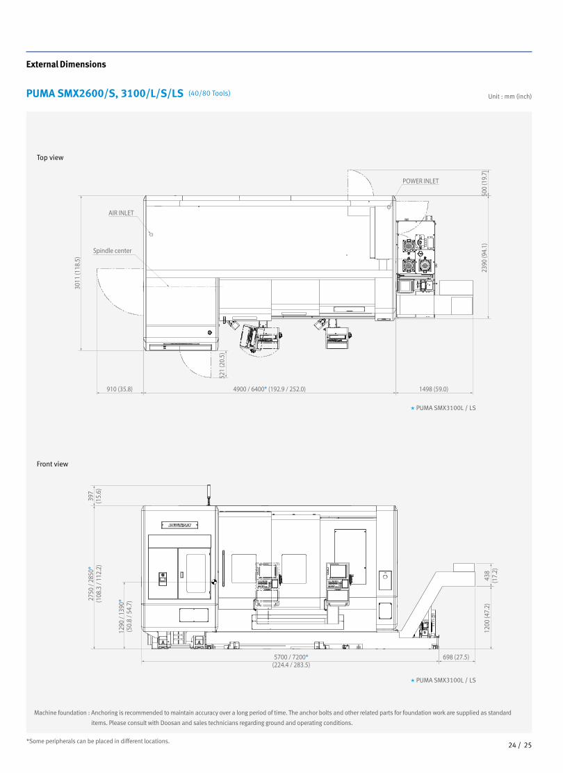
PUMA SMX2600/S, 3100/L/S/LS (40/80 Tools)
Front view
Top view
AIR INLET
Spindle center
POWER INLET
4900 / 6400* (192.9 / 252.0)
5700 / 7200*(224.4 / 283.5)
698 (27.5)
1498 (59.0)910 (35.8)
2390
(94.
1)12
00 (4
7.2)
438
(17.
2)
500
(19.
7)
3011
(118
.5)
521
(20.
5)
1290
/ 13
90*
(50.
8 / 5
4.7)
397
(15.
6)27
50 /
2850
*(1
08.3
/ 11
2.2)
AIR INLET
Spindle center
POWER INLET
4900 / 6400* (192.9 / 252.0)
5700 / 7200*(224.4 / 283.5)
698 (27.5)
1498 (59.0)910 (35.8)
2390
(94.
1)12
00 (4
7.2)
438
(17.
2)
500
(19.
7)
3011
(118
.5)
521
(20.
5)
1290
/ 13
90*
(50.
8 / 5
4.7)
397
(15.
6)27
50 /
2850
*(1
08.3
/ 11
2.2)
* PUMA SMX3100L / LS
* PUMA SMX3100L / LS
Machine foundation : Anchoring is recommended to maintain accuracy over a long period of time. The anchor bolts and other related parts for foundation work are supplied as standard
items. Please consult with Doosan and sales technicians regarding ground and operating conditions.
*Some peripherals can be placed in different locations.2524 /
Unit : mm (inch)
External Dimensions

Front view
Top view
Machine foundation : Anchoring is recommended to maintain accuracy over a long period of time. The anchor bolts and other related parts for foundation work are
supplied as standard items. Please consult with Doosan and sales technicians regarding ground and operating conditions.
*Some peripherals can be placed in different locations.
Unit : mm (inch)PUMA SMX2600ST/ 3100ST (40/80 Tools)
625
(24.
6)30
21(1
18.9
)50
0(1
9.7)
100 R370(14.6)
CHIP BUCKET40 Tools : 5790 (228.0) / 80 Tools : 5925 (233.3)
1000 (39.4) (Maintenance space)
C=28
20 (1
11.0
)+b
1360
(53.
5)+b
397
(15.
6)
c
380L
720(28.3)
a40 Tools : 4900 (192.9) / 80 Tools : 5035 (198.2)
SMX2600: 1390 (54.7)(SMX3100: 1370(53.9))
Length with side chip conveyor40 Tools : 4900 (192.9)+a / 80 Tools : 5035 (198.2)+a
Chip conveyor type a b cHinge belt type 1498 (59.0) 0 1100 (43.3)Drum filter+Hinge scraper type 2386 (93.9) 70 (2.8) 1050 (41.3)
2726 /
PUMA
SMX
series
External DimensionsProduct Overview
Basic information
Basic Structure
Main Units
Machine
Performance
CUFOS
Detailed
Information
Options
Diagrams
Specifications
Customer Support
Service

Front view
Top view
Machine foundation : Anchoring is recommended to maintain accuracy over a long period of time. The anchor bolts and other related parts for foundation work are supplied as standard items.
Please consult with Doosan and sales technicians regarding ground and operating conditions.
*Some peripherals can be placed in different locations.
PUMA SMX2600ST/ 3100ST (120 Tools) Unit : mm (inch)
SMX2600: 2207 (86.9)(SMX3100: 2187 (86.1))
(380L)
c
215
(8.5
)
625
(24.
6)30
21(1
18.9
)50
0(1
9.7)
397
(15.
6)
1000 (39.4)(Maintenance space)
1360
(53.
5) +
b
2820
(111
.0)+
b
100 R370(14.6)
a120 Tools : 5217 (205.4)
120 Tools : 6607 (260.1)
Length with side chip conveyor120 Tools : 5217 (205.4) +a
Chip conveyor type a b cHinge belt type 1498 (59.0) 0 1100 (43.3)Drum filter+Hinge scraper type 2386 (93.9) 70 (2.8) 1050 (41.3)
SMX2600: 2207 (86.9)(SMX3100: 2187 (86.1))
(380L)
c
215
(8.5
)
625
(24.
6)30
21(1
18.9
)50
0(1
9.7)
397
(15.
6)
1000 (39.4)(Maintenance space)
1360
(53.
5) +
b
2820
(111
.0)+
b
100 R370(14.6)
a120 Tools : 5217 (205.4)
120 Tools : 6607 (260.1)
Length with side chip conveyor120 Tools : 5217 (205.4) +a
2726 /

2928 /
PUMA
SMX
series
PUMA SMX2600/SMX3100 series
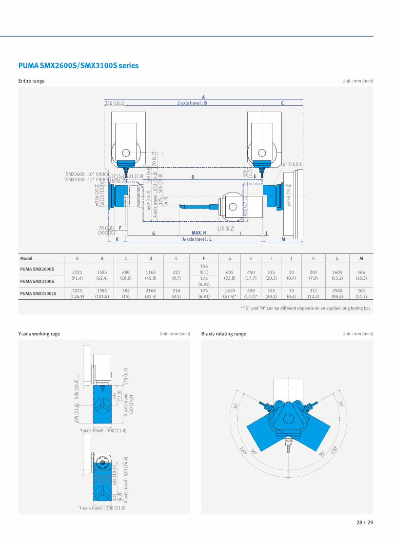
Entire range
Y-axis working rage B-axis rotating rangeUnit : mm (inch) Unit : mm (inch)
Working Range
Unit : mm (inch)
X-ax
is tr
avel
630
(24.
8)
X-ax
is tr
avel
: 63
0 (2
4.8)
Y-axis travel : 300 (11.8)
Y-axis travel : 300 (11.8)
505
(19.
9)29
5 (1
1.6)
335
(13.
2)50
5 (1
9.9
)12
5(4
.9)
170
(6.7
)
90
30
30
90
120 120
150 (5.9)
150 (5.9)
D
A
A-axis travel : N
Z-axis travel : B C256 (10.1)
SMX2600 : 10" CHUCK[SMX3100 : 12" CHUCK]
O
E
170 (6.7)K LMAX. JI
70 (2.8) H[50(2.0)]
[157(6.2)]
M
201 (7.9)137 (5.4)
168
(6.6
)46
2 (1
8.2)
170
(6.7
)X-
axis
trav
el :
630
(24.
8)50
5 (1
9.9)
FG12
5(4
.9)
254(
10.0
)[
315
(12.
4)]
X-ax
is tr
avel
630
(24.
8)
X-ax
is tr
avel
: 63
0 (2
4.8)
Y-axis travel : 300 (11.8)
Y-axis travel : 300 (11.8)
505
(19.
9)29
5 (1
1.6)
335
(13.
2)50
5 (1
9.9
)12
5(4
.9)
170
(6.7
)
90
30
30
90
120 120
150 (5.9)
150 (5.9)
D
A
A-axis travel : N
Z-axis travel : B C256 (10.1)
SMX2600 : 10" CHUCK[SMX3100 : 12" CHUCK]
O
E
170 (6.7)K LMAX. JI
70 (2.8) H[50(2.0)]
[157(6.2)]
M
201 (7.9)137 (5.4)16
8 (6
.6)
462
(18.
2)17
0 (6
.7)
X-ax
is tr
avel
: 63
0 (2
4.8)
505
(19.
9)
FG12
5(4
.9)
254(
10.0
)[
315
(12.
4)]
Model A B C D E F G H I J K L M N O
PUMA SMX26002321(91.4)
1585(62.4)
480(18.9)
1166(45.9)
218(8.6)
237(9.3)
393(15.5)
156(6.1) 608
(23.9)450
(17.7)515
(20.3)10
(0.4)247(9.7)
1562(61.5)
463(18.2)
PUMA SMX3100176
(6.93)
PUMA SMX3100L3223
(126.9)2585
(101.8)382(15)
2168(85.4)
216(8.5)
195(7.7)
435(17.1)
176(6.93)
1610(63.4)*
450(17.7)*
515(20.3)
12(0.5)
313(12.3)
2500(98.4)
361(14.2)
* "I" and "J" can be different depends on an applied long boring bar
Product Overview
Basic information
Basic Structure
Main Units
Machine
Performance
CUFOS
Detailed
Information
Options
Diagrams
Specifications
Customer Support
Service
2928 /
PUMA SMX2600S/SMX3100S series
Entire range
Y-axis working rage B-axis rotating rangeUnit : mm (inch) Unit : mm (inch)
Unit : mm (inch)
J170 (6.7)
IMAX. HA-axis travel : L
70 (2.8) F[50(2.0)]
462
(18.
2)
254
(10.
0)
254
(10.
0)
[ 3
15 (1
2.4)
]
E
505
(19.
9)12
5(4
.9)
170
(6.7
)X-
axis
trav
el :
630
(24.
8)201 (7.9)
168
(6.6
)
[157(6.2)]137 (5.4)
CA
Z-axis travel : B256 (10.1)
X-ax
is tr
avel
630
(24.
8)
X-ax
is tr
avel
: 63
0 (2
4.8)
Y-axis travel : 300 (11.8)
Y-axis travel : 300 (11.8)
505
(19.
9)29
5 (1
1.6)
335
(13.
2)50
5 (1
9.9
)12
5(4
.9)
170
(6.7
)
150 (5.9)
150 (5.9)
SMX2600 : 10" CHUCK[SMX3100 : 12" CHUCK]
90
30
30
90
D
MG
K
195
(7.7
)43
5 (1
7.1)
10" CHUCK
120 120
Model A B C D E F G H I J K L M
PUMA SMX2600S2321 (91.4)
1585 (62.4)
480 (18.9)
1163 (45.8)
221(8.7)
156 (6.1) 605
(23.8)450
(17.7)515
(20.3)10
(0.4)201(7.9)
1605(63.2)
466(18.3)
PUMA SMX3100S176
(6.93)
PUMA SMX3100LS3223
(126.9)2585
(101.8)382(15)
2168(85.4)
216(8.5)
176 (6.93)
1610 (63.4)*
450 (17.7)*
515 (20.3)
10(0.4)
311 (12.2)
2500 (98.4)
363 (14.3)
J170 (6.7)
IMAX. HA-axis travel : L
70 (2.8) F[50(2.0)]
462
(18.
2)
254
(10.
0)
254
(10.
0)
[ 3
15 (1
2.4)
]
E
505
(19.
9)12
5(4
.9)
170
(6.7
)X-
axis
trav
el :
630
(24.
8)201 (7.9)
168
(6.6
)
[157(6.2)]137 (5.4)
CA
Z-axis travel : B256 (10.1)
X-ax
is tr
avel
630
(24.
8)
X-ax
is tr
avel
: 63
0 (2
4.8)
Y-axis travel : 300 (11.8)
Y-axis travel : 300 (11.8)
505
(19.
9)29
5 (1
1.6)
335
(13.
2)50
5 (1
9.9
)12
5(4
.9)
170
(6.7
)
150 (5.9)
150 (5.9)
SMX2600 : 10" CHUCK[SMX3100 : 12" CHUCK]
90
30
30
90
D
MG
K19
5(7
.7)
435
(17.
1)
10" CHUCK120 12
0
* "G" and "H" can be different depends on an applied long boring bar

3130 /
PUMA
SMX
series
PUMA SMX2600ST/SMX3100ST
Entire range
Unit : mm (inch) Unit : mm (inch)
Working Range
Unit : mm (inch)
Y-axis working rage B-axis rotating range
90
30
30
90
120 120
880 (34.6)
Minimum distance between milling spindle and lower turret when both units are located on the respective end point of minus storke
1540 (60.6) (Z2-axis travel) 243 (9.6)
2 (0.1)(+0T)
79 (3.1)
1540 (60.6) (A-axis travel)
170 (6.7) (206 (8.1))
ø254
(10.
0)
1897 (74.7)(10" Chuck)77 (3.0)(10" Chuck)57 (2.2)(12" Chuck)
176.5 (6.9)(12" Chuck)
134 (5.3)(12" )114 (4.5)(10" )Q - setter
Cover line
ATC position
245 (9.6) (ATC stroke)
214 (8.4)
250 (9.8)
5 (0
.2)
40 (1.6) 1168 (46.0) 134(5.3)
220 (
8.7)
43 (1
.7)43
2 (1
7.0)
7 (0.3)
82(3.2)
25 (1
.0)
161 (6.3)
19 (0.7)
137 (5.4) (10" Chuck) 10" Chuck157.5 (6.2) (12" Chuck)
345
(13.
6)17
0 (6
.7)
223
(8.8
)70
(2.8
)40
2 (1
5.8)
125
(4.9
)40
0 (1
5.7)
695
(27.
4)
695
(27.
4) (X
1-ax
is tr
avel
)
1585 (62.4)(Z1-axis travel) 175 (6.9)
29 (1.1)
156 (6.1)(10" Chuck) 156 (6.1)
(329 (13.0))
170 (6.7)
235
(9.3
)(X
2-ax
is tr
avel
)28
5.5
(11.
2)
45 (1.8)
1917 (75.5)(12" Chuck)
300 (11.8) (Y-axis travel)
ATC position
5 (0
.2)
170 (
6.7)
400
(15.
7)
203(8.0)245.4
(9.7) 110(4.3) 182.5(7.2) 69
5 (2
7.4)
(X-a
xis
trave
l)
ø254
(10.
0)(1
0" C
huck
)
ø315
(12.
4)(1
2" C
huck
)
ø654 (25.7)
ø660 (26.0)
ø640 (25.2)
ø405 (15.9)
(Swing over lower saddle+ end stroke position)
(Max. turning dia. of lower turret)
235 (9.3)
(Swing over bed)
(Max. Swing dia.)
45̊
Product Overview
Basic information
Basic Structure
Main Units
Machine
Performance
CUFOS
Detailed
Information
Options
Diagrams
Specifications
Customer Support
Service

3130 /
Unit : mm (inch)
Ref. point Ref. point
D
A
D
A
B
C
1540 (60.6) (Z2-axis travel) 1540 (60.6) (Z2-axis travel)
1540 (60.6) (Z2-axis travel)1540 (60.6) (Z2-axis travel)
243 (9.6) 243 (9.6)
822 (32.4)(Z2 - ref. point) 718 (28.3)
822 (32.4)(Z2 - ref. point) 718 (28.3)30
(1.2)105 (4.1)243 (9.6)
(7)(0.3) 822 (32.4)(Z2 - ref. point) 718 (28.3) 77 (3.0)
243 (9.6)
822 (32.4)(Z2 - ref. point) 718 (28.3)46 (1.8)9 (0.4) 81 (3.2) (6 (0.2))
Cover lineRef. pointRef. point
(21 (0.8)) 140(5.5)
30(1.2) 191 (7.5)
(52 (2.0))
Cover line
93 (3.7) 46 (1.8)
182.
5(7
.2)
182.
5(7
.2)
10 (0.4
)80 (3.1
)14
5(5
.7)
58 (2.3)
2 (0
.1)
22 (0.9
)23 (0.9
)
235 (9.
3)(X
2-ax
is tr
avel
)20
(0.8
)
103
(4.1
)
10 2 (0.1)
210 (8.
3)25
(1.0
)23
5 (9
.3)
(X2-
axis
trav
el)
(X2-
axis
trav
el)
1426 (56.1) 133 (5.2)
92(3.6)
41(1.6)60
(2.4) 2.5 (0.1)50
(2.0)
156 (6.1)114(4.5)
156 (6.1)45(1.8)
26 (1.0)
1540 (60.6) (A-axis travel)
1540 (60.6) (A-axis travel)
1459 (57.4)81(3.2)
156(6.1)
37(1.5)
9(0.4)
45(1.8)
161(6.3)
1540 (60.6) (A-axis travel)
1540 (60.6) (A-axis travel)156(6.1)
56 (2.2)
45(1.8)
1483 (58.4)
1416 (55.7) 164(6.5)
154(6.1)
2 (0
.1)
10(0.4)
156(6.1)
114(4.5)
124(4.9)
87(3.4)
60 (2.4)
50(2.0)
156(6.1)
145(5.7)
156(6.1)
117(4.6)
6057
32 73 8079 (3.1)
10" Chuck 10" Chuck
10" Chuck
191 (7.5) 57 (2.2)
15 (0.6)
B
D
CEE
A
45(1.8)
156(6.1)
5 (0.2)
Cover line
Max. tool length on right side
Max. tool length on right side
Cover line
Single od holder
Double od holder
ø254
(10.
0)
ø254
(10.
0)
ø254
(10.
0)
ø254
(10.
0)
22 (0.9
)23 (0.9
)
10 (0.4
)65 (2.6
)160
(6.3
)
182.
5(7
.2)
103
(4.1
)21
0(8
.3)
235
(9.3
)
2 (0
.1)
25 (1.0
)
40 110
(4.3
)20
3(8
.0)
32 (1.3
)
235
182.
5(7
.2)
(X2-
axis
trav
el)
B
CE
D
A
B
CE
22 (0.9
)23 (0.9
)
60 (2.4)
50(2.0)
60(2.4)
50(2.0)60
(2.4)50
(2.0)
23 (0.9
)22 (0.9
)
Ref. point Ref. point
D
A
D
A
B
C
1540 (60.6) (Z2-axis travel) 1540 (60.6) (Z2-axis travel)
1540 (60.6) (Z2-axis travel)1540 (60.6) (Z2-axis travel)
243 (9.6) 243 (9.6)
822 (32.4)(Z2 - ref. point) 718 (28.3)
822 (32.4)(Z2 - ref. point) 718 (28.3)30
(1.2)105 (4.1)243 (9.6)
(7)(0.3) 822 (32.4)(Z2 - ref. point) 718 (28.3) 77 (3.0)
243 (9.6)
822 (32.4)(Z2 - ref. point) 718 (28.3)46 (1.8)9 (0.4) 81 (3.2) (6 (0.2))
Cover lineRef. pointRef. point
(21 (0.8)) 140(5.5)
30(1.2) 191 (7.5)
(52 (2.0))
Cover line
93 (3.7) 46 (1.8)
182.
5(7
.2)
182.
5(7
.2)
10 (0.4
)80 (3.1
)14
5(5
.7)
58 (2.3)
2 (0
.1)
22 (0.9
)23 (0.9
)
235 (9.
3)(X
2-ax
is tr
avel
)20
(0.8
)
103
(4.1
)
10 2 (0.1)
210 (8.
3)25
(1.0
)23
5 (9
.3)
(X2-
axis
trav
el)
(X2-
axis
trav
el)
1426 (56.1) 133 (5.2)
92(3.6)
41(1.6)60
(2.4) 2.5 (0.1)50
(2.0)
156 (6.1)114(4.5)
156 (6.1)45(1.8)
26 (1.0)
1540 (60.6) (A-axis travel)
1540 (60.6) (A-axis travel)
1459 (57.4)81(3.2)
156(6.1)
37(1.5)
9(0.4)
45(1.8)
161(6.3)
1540 (60.6) (A-axis travel)
1540 (60.6) (A-axis travel)156(6.1)
56 (2.2)
45(1.8)
1483 (58.4)
1416 (55.7) 164(6.5)
154(6.1)
2 (0
.1)
10(0.4)
156(6.1)
114(4.5)
124(4.9)
87(3.4)
60 (2.4)
50(2.0)
156(6.1)
145(5.7)
156(6.1)
117(4.6)
6057
32 73 80
79 (3.1)
10" Chuck 10" Chuck
10" Chuck
191 (7.5) 57 (2.2)
15 (0.6)
B
D
CEE
A
45(1.8)
156(6.1)
5 (0.2)
Cover line
Max. tool length on right side
Max. tool length on right side
Cover line
Single od holder
Double od holder
ø254
(10.
0)
ø254
(10.
0)
ø254
(10.
0)
ø254
(10.
0)
22 (0.9
)23 (0.9
)
10 (0.4
)65 (2.6
)160
(6.3
)
182.
5(7
.2)
103
(4.1
)21
0(8
.3)
235
(9.3
)
2 (0
.1)
25 (1.0
)
40 110
(4.3
)20
3(8
.0)
32 (1.3
)
235
182.
5(7
.2)
(X2-
axis
trav
el)
B
CE
D
A
B
CE
22 (0.9
)23 (0.9
)
60 (2.4)
50(2.0)
60(2.4)
50(2.0)60
(2.4)50
(2.0)
23 (0.9
)22 (0.9
)
Angular Milling Head
ID Tool Holder
Straight Milling Head
OD Tool Holder
Model Unit A B C D E
PUMA SMX2600ST (10"Chuck) mm (inch) ø254 (10.0) 156 (6.1) 1897 (74.7) 114 (4.5) 77 (3.0)
PUMA SMX3100ST (12" Chuck) mm (inch) ø315 (12.4) 176.5 (6.9) 1917 (75.5) 134 (5.3) 57 (2.2)

Tool Interference Diagram of Lower Turret
Unit : mm (inch)
For Turning (12 stations)
For Turn-Milling (12 stations, BMT65P)
PUMA SMX2600ST/SMX3100ST
PUMA SMX2600ST/SMX3100ST
Unit : mm (inch)
Ø186(7.3)
Ø186(7.3)
Ø40 (1.6) (Max. boring bar dia.)
Ø634 (25.0)(Max. swing dia.)
Ø405 (15.9)(Lower turret: Max. turning dia.)
103(4.1)
182.5(7.2)
182.5(7.2)
110(4.3)
75(3.0)
35(1.4)
35(1.4)
90(3.5)
203(8.0)
32(1.3)
235 (9.3)(X2-axis travel)
Ø403
(15.9)
Ø268
(10.
6)
Ø268(10.6)
102
(4.0)
Ø254(1
0.0)
Ø254
(10.0)
Ø254
(10.0)
110
(4.3
)
Spindle center
Ø654 (25.7)(Max. swing dia.)
Ø40 (1.6) (Max. boring bar dia.)
110
(4.3
)
Ø186(7.3)
86(3.4) 58(2.3)
Ø20 (0
.8)
Ø403(15.9)Ø254
(10.0)
Ø254(1
0.0)
Ø186(7.3) Ø405 (15.9)
(Lower turret: Max. turning dia.)
103(4.1)
182.5(7.2)
182.5(7.2)
110(4.3)
75(3.0)
35(1.4)
35(1.4)
90(3.5)
203(8.0)
32(1.3)
235 (9.3)(X2-axis travel)
Ø268
(10.
6)
Ø268(10.6)
Ø254
(10.0)
Spindle center
102
(4.0)
3332 /
PUMA
SMX
series
Product Overview
Basic information
Basic Structure
Main Units
Machine
Performance
CUFOS
Detailed
Information
Options
Diagrams
Specifications
Customer Support
Service

PUMA SMX2600ST/SMX3100ST
Tooling System
Unit : mm (inch)
For Turn (12st)
TURNING TOOL
ID HOLDER
PLUG
OD, FACE, CUT-OFFOD Tool Holder
OD Tool
Cut-off tool
Boring Bar Sleeves
Boring Bar
U-Drill
Drill
U-drill Sleeves
Drill Socket
Straight Milling Head For Side Cutting
Holder Coverfor U-Drill
Angular Milling Head For Face Cutting
Dummy Plug
Double OD Tool Holder
Face Tool Holder
Cut-off Tool Holder
ID Tool Holder
Ø10 (0.4)-H40 Ø12 (0.5)-H40Ø16 (0.6)-H40 Ø20 (0.8)-H40Ø25 (1.0)-H40 Ø32 (1.3)-H40
Ø20 (0.8)-H40Ø25 (1.0)-H40Ø32 (1.3)-H40
MT NO.1MT NO.2MT NO.3
COLLET
□25 (1.0)
□25 (1.0)
Rotary tool
For Turn-Milling (12ST)
BMT65P
Ø3~20 (0.12~0.8)
Standard for turning turret
Standard for turn-milling turret
3332 /

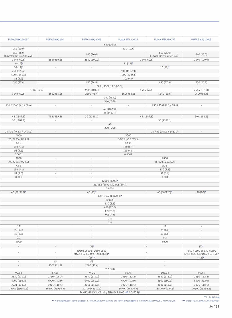
PUMA SMX 2600 /3100
Item Unit PUMA SMX2600 PUMA SMX2600S PUMA SMX2600ST PUMA SMX3100 PUMA SMX3100L PUMA SMX3100S PUMA SMX3100ST PUMA SMX3100LS
Capacity Swing over bed mm (inch) 660 (26.0) 660 (26.0)
Recom. turning diameter mm (inch) 255 (10.0) 255 (10.0) 315 (12.4)
Max. turning diameter mm (inch) 660 (26.0)660 (26.0)
[ Lower turret : 405 (15.9) ]660 (26.0)
660 (26.0) [ Lower turret : 405 (15.9) ]
660 (26.0)
Max. turning length mm (inch) 1540 (60.6) 1540 (60.6) 1540 (60.6) 2540 (100.0) 1540 (60.6) 2540 (100.0)
Chuck sizeLeft spindle inch 10 {12}* 10 {12}* 12 {15}*Right spindle inch - 10 {12}* 10 {12}* - - 10 {12}*
Chuck work weight (include chuck) kg (lb) 260 (573.2) 260 (573.2) 500 (1102.3)
Shaft work weight (include chuck) kg (lb) 520 (1146.4) 520 (1146.4) 1000 (2204.6)
Bar working diameter mm (inch) 81 (3.2) 81 (3.2) 102 (4.0)
Travels
Travel distance
X-axis mm (inch) 630 (24.8) 695 (27.4) 630 (24.8) 695 (27.4) 630 (24.8)
Y-axis mm (inch) 300 (±150) (11.8 (±5.9)) 300 (±150) (11.8 (±5.9))
Z-axis mm (inch) 1585 (62.4) 1585 (62.4) 2585 (101.8) 1585 (62.4) 2585 (101.8)
A-axis** mm (inch) 1562 (61.5) 1605 (63.2) 1540 (60.6) 1562 (61.5) 2500 (98.4) 1605 (63.2) 1540 (60.6) 2500 (98.4)
B-axis deg 240 (±120) 240 (±120)
C1-axis / C2-axis deg 360 / 360 360 / 360
X2-axis / Z2-axis mm (inch) - - 235 / 1540 (9.3 / 60.6) - - - 235 / 1540 (9.3 / 60.6) -
Rapid traverse rate
X-axis m/min (ipm) 48 (1889.8) 48 (1889.8)
Y-axis m/min (ipm) 36 (1417.3) 36 (1417.3)
Z-axis m/min (ipm) 48 (1889.8) 48 (1889.8) 48 (1889.8) 30 (1181.1) 48 (1889.8) 30 (1181.1)
A-axis** m/min (ipm) - 30 (1181.1) 30 (1181.1) - - 30 (1181.1)
B-axis r/min 40 40
C1-axis / C2-axis r/min 200 / 200 200 / 200
X2-axis / Z2-axis m/min (ipm) - - 24 / 36 (944.9 / 1417.3) - - - 24 / 36 (944.9 / 1417.3) -
Left spindle
Max. spindle speed r/min 4000 4000 3000
Spindle motor power (30min/cont.) kW (Hp) 26/22 (34.9/29.5) 26/22 (34.9/29.5) 30/25 (40.2/33.5)
Spindle nose ASA A2-8 A2-8 A2-11
Spindle bearing diameter (Front) mm (inch) 130 (5.1) 130 (5.1) 160 (6.3)
Spindle through hole mm (inch) 91 (3.6) 91 (3.6) 115 (4.5)
Min. spindle indexing angle (C1-axis) deg 0.0001 0.0001 0.0001
Right spindle
Max. spindle speed r/min - 4000 4000 - - 4000
Spindle motor power (30min/cont.) kW (Hp) - 26/22 (34.9/29.5) 26/22 (34.9/29.5) - - 26/22 (34.9/29.5)
Spindle nose ASA - A2-8 A2-8 - - A2-8
Spindle bearing diameter (Front) mm (inch) - 130 (5.1) 130 (5.1) - - 130 (5.1)
Spindle through hole mm (inch) - 91 (3.6) 91 (3.6) - - 91 (3.6)
Min. spindle indexing angle (C2-axis) deg - 0.001 0.001 - - 0.001
Milling spindle Max. spindle speed r/min 12000 {8000}* 12000 {8000}*Milling spindle motor power (2.5min/10min/Cont.) kW (Hp) 26/18.5/15 (34.9/24.8/20.1) 26/18.5/15 (34.9/24.8/20.1)
Min. spindle indexing angle (B-axis) deg 0.0001 0.0001
Automatic Tool Changer
Tool storage capa. (Max.) ea 40 {80}* 40 {80/120}* 40 {80}* 40 {80/120}* 40 {80}*Tool shank - CAPTO C6 {HSK-A63}* CAPTO C6 {HSK-A63}*Max. tool diameter continous mm (inch) 90 (3.5) 90 (3.5)
Max. tool diameter without adjacent tools mm (inch) 130 (5.1) 130 (5.1)
Max. tool length mm (inch) 450 (17.7) 450 (17.7)
Max. tool weight kg (lb) 12 (26.5) 12 (26.5)
Max. tool moment N·m (ft-lbs) 9.8 (7.2) 9.8 (7.2)
Tool change time (T-T-T)Tool-to-tool sec 1.8 1.8
Chip-to-chip sec 7.8 7.8
Lower turret No. of tool stations ea - 12 - 12 -
OD tool size mm (inch) - 25 (1.0) - 25 (1.0) -
Max. boring bar size mm (inch) - 40 (1.6) - 40 (1.6) -
Turret Indexing time (1 station swivel) s - 0.2 - 0.2 -
Max. rotary tool speed r/min - 5000 - 5000 -
Long Boring BarMagazine (option for SMX 3100L/LS)
Tool storage capacity (Max.) ea - - - {3}* - {3}*
Max. tool size mm (inch) - - -{Ø60 x L600 or Ø30 x L800
(Ø2.4 x L23.6 or Ø1.2 x L31.5)}*-
{Ø60 x L600 or Ø30 x L800(Ø2.4 x L23.6 or Ø1.2 x L31.5)}*
Max. tool weight kg (lb) - - - {15}* - {15}*Tail Stock Quill bore taper MT #5 - - #5 #5 -
Quill travel mm (inch) 1562 (61.5) - - 1562 (61.5) 2500 (98.4) -
Coolant Coolant pump motor power kW (Hp) 2.2 (3.0) 2.2 (3.0)
Power source Electric power supply (rated capacity) kVA 64.61 89.91 99.93 67.61 74.25 94.71 103.93 99.44
Machine Dimensions
Height mm (inch) 2750 (108.3) 2750 (108.3) 2820 (111.0) 2750 (108.3) 2850 (112.2) 2850 (112.2) 2820 (111.0) 2850 (112.2)
Length mm (inch) 4900 (192.9) 4900 (192.9) 4900 (192.9) 4900 (192.9) 6400 (252.0) 4900 (192.9) 4900 (192.9) 6400 (252.0)
Width mm (inch) 3011 (118.5) 3011 (118.5) 3021 (118.9) 3011 (118.5) 3011 (118.5) 3011 (118.5) 3021 (118.9) 3011 (118.5)
Weight kg (lb) 15800 (34832.5) 16200 (35714.4) 18000 (39682.6) 16300 (35934.8) 20100 (44312.3) 16700 (36816.7) 18500 (40784.9) 20500 (45194.1)
Control NC system FANUC31i {FANUC31i-5 / SIEMENS 840D***/ CUFOS}* FANUC31i {FANUC31i-5 / SIEMENS 840D*** / CUFOS}*
* { } : Optimal
** A-axis is travel of servo tail stock in PUMA SXM2600, 3100/L and travel of right spindle in PUMA SMX2600S/ST, 3100S/ST/LS. *** Except PUMA SMX2600ST/3100ST
Machine Specifications
Standard Features
- Tool and tool box
- Through spindle coolant for milling
spindle
- Door interlock
- Level bolt and plate
- Servo tail stock
(for PUMA SMX2600/3100/3100L)
- Soft jaws
- Spindle head cooling system
- Hydraulic unit
- Automatic coolant system
- Work lamp
- Standard hydraulic chuck
- X-axis linear scale
(only PUMA SMX3100L/LS)
3534 /
PUMA
SMX
series
Product Overview
Basic information
Basic Structure
Main Units
Machine
Performance
CUFOS
Detailed
Information
Options
Diagrams
Specifications
Customer Support
Service
Item Unit PUMA SMX2600 PUMA SMX2600S PUMA SMX2600ST PUMA SMX3100 PUMA SMX3100L PUMA SMX3100S PUMA SMX3100ST PUMA SMX3100LS
Capacity Swing over bed mm (inch) 660 (26.0) 660 (26.0)
Recom. turning diameter mm (inch) 255 (10.0) 255 (10.0) 315 (12.4)
Max. turning diameter mm (inch) 660 (26.0)660 (26.0)
[ Lower turret : 405 (15.9) ]660 (26.0)
660 (26.0) [ Lower turret : 405 (15.9) ]
660 (26.0)
Max. turning length mm (inch) 1540 (60.6) 1540 (60.6) 1540 (60.6) 2540 (100.0) 1540 (60.6) 2540 (100.0)
Chuck sizeLeft spindle inch 10 {12}* 10 {12}* 12 {15}*Right spindle inch - 10 {12}* 10 {12}* - - 10 {12}*
Chuck work weight (include chuck) kg (lb) 260 (573.2) 260 (573.2) 500 (1102.3)
Shaft work weight (include chuck) kg (lb) 520 (1146.4) 520 (1146.4) 1000 (2204.6)
Bar working diameter mm (inch) 81 (3.2) 81 (3.2) 102 (4.0)
Travels
Travel distance
X-axis mm (inch) 630 (24.8) 695 (27.4) 630 (24.8) 695 (27.4) 630 (24.8)
Y-axis mm (inch) 300 (±150) (11.8 (±5.9)) 300 (±150) (11.8 (±5.9))
Z-axis mm (inch) 1585 (62.4) 1585 (62.4) 2585 (101.8) 1585 (62.4) 2585 (101.8)
A-axis** mm (inch) 1562 (61.5) 1605 (63.2) 1540 (60.6) 1562 (61.5) 2500 (98.4) 1605 (63.2) 1540 (60.6) 2500 (98.4)
B-axis deg 240 (±120) 240 (±120)
C1-axis / C2-axis deg 360 / 360 360 / 360
X2-axis / Z2-axis mm (inch) - - 235 / 1540 (9.3 / 60.6) - - - 235 / 1540 (9.3 / 60.6) -
Rapid traverse rate
X-axis m/min (ipm) 48 (1889.8) 48 (1889.8)
Y-axis m/min (ipm) 36 (1417.3) 36 (1417.3)
Z-axis m/min (ipm) 48 (1889.8) 48 (1889.8) 48 (1889.8) 30 (1181.1) 48 (1889.8) 30 (1181.1)
A-axis** m/min (ipm) - 30 (1181.1) 30 (1181.1) - - 30 (1181.1)
B-axis r/min 40 40
C1-axis / C2-axis r/min 200 / 200 200 / 200
X2-axis / Z2-axis m/min (ipm) - - 24 / 36 (944.9 / 1417.3) - - - 24 / 36 (944.9 / 1417.3) -
Left spindle
Max. spindle speed r/min 4000 4000 3000
Spindle motor power (30min/cont.) kW (Hp) 26/22 (34.9/29.5) 26/22 (34.9/29.5) 30/25 (40.2/33.5)
Spindle nose ASA A2-8 A2-8 A2-11
Spindle bearing diameter (Front) mm (inch) 130 (5.1) 130 (5.1) 160 (6.3)
Spindle through hole mm (inch) 91 (3.6) 91 (3.6) 115 (4.5)
Min. spindle indexing angle (C1-axis) deg 0.0001 0.0001 0.0001
Right spindle
Max. spindle speed r/min - 4000 4000 - - 4000
Spindle motor power (30min/cont.) kW (Hp) - 26/22 (34.9/29.5) 26/22 (34.9/29.5) - - 26/22 (34.9/29.5)
Spindle nose ASA - A2-8 A2-8 - - A2-8
Spindle bearing diameter (Front) mm (inch) - 130 (5.1) 130 (5.1) - - 130 (5.1)
Spindle through hole mm (inch) - 91 (3.6) 91 (3.6) - - 91 (3.6)
Min. spindle indexing angle (C2-axis) deg - 0.001 0.001 - - 0.001
Milling spindle Max. spindle speed r/min 12000 {8000}* 12000 {8000}*Milling spindle motor power (2.5min/10min/Cont.) kW (Hp) 26/18.5/15 (34.9/24.8/20.1) 26/18.5/15 (34.9/24.8/20.1)
Min. spindle indexing angle (B-axis) deg 0.0001 0.0001
Automatic Tool Changer
Tool storage capa. (Max.) ea 40 {80}* 40 {80/120}* 40 {80}* 40 {80/120}* 40 {80}*Tool shank - CAPTO C6 {HSK-A63}* CAPTO C6 {HSK-A63}*Max. tool diameter continous mm (inch) 90 (3.5) 90 (3.5)
Max. tool diameter without adjacent tools mm (inch) 130 (5.1) 130 (5.1)
Max. tool length mm (inch) 450 (17.7) 450 (17.7)
Max. tool weight kg (lb) 12 (26.5) 12 (26.5)
Max. tool moment N·m (ft-lbs) 9.8 (7.2) 9.8 (7.2)
Tool change time (T-T-T)Tool-to-tool sec 1.8 1.8
Chip-to-chip sec 7.8 7.8
Lower turret No. of tool stations ea - 12 - 12 -
OD tool size mm (inch) - 25 (1.0) - 25 (1.0) -
Max. boring bar size mm (inch) - 40 (1.6) - 40 (1.6) -
Turret Indexing time (1 station swivel) s - 0.2 - 0.2 -
Max. rotary tool speed r/min - 5000 - 5000 -
Long Boring BarMagazine (option for SMX 3100L/LS)
Tool storage capacity (Max.) ea - - - {3}* - {3}*
Max. tool size mm (inch) - - -{Ø60 x L600 or Ø30 x L800
(Ø2.4 x L23.6 or Ø1.2 x L31.5)}*-
{Ø60 x L600 or Ø30 x L800(Ø2.4 x L23.6 or Ø1.2 x L31.5)}*
Max. tool weight kg (lb) - - - {15}* - {15}*Tail Stock Quill bore taper MT #5 - - #5 #5 -
Quill travel mm (inch) 1562 (61.5) - - 1562 (61.5) 2500 (98.4) -
Coolant Coolant pump motor power kW (Hp) 2.2 (3.0) 2.2 (3.0)
Power source Electric power supply (rated capacity) kVA 64.61 89.91 99.93 67.61 74.25 94.71 103.93 99.44
Machine Dimensions
Height mm (inch) 2750 (108.3) 2750 (108.3) 2820 (111.0) 2750 (108.3) 2850 (112.2) 2850 (112.2) 2820 (111.0) 2850 (112.2)
Length mm (inch) 4900 (192.9) 4900 (192.9) 4900 (192.9) 4900 (192.9) 6400 (252.0) 4900 (192.9) 4900 (192.9) 6400 (252.0)
Width mm (inch) 3011 (118.5) 3011 (118.5) 3021 (118.9) 3011 (118.5) 3011 (118.5) 3011 (118.5) 3021 (118.9) 3011 (118.5)
Weight kg (lb) 15800 (34832.5) 16200 (35714.4) 18000 (39682.6) 16300 (35934.8) 20100 (44312.3) 16700 (36816.7) 18500 (40784.9) 20500 (45194.1)
Control NC system FANUC31i {FANUC31i-5 / SIEMENS 840D***/ CUFOS}* FANUC31i {FANUC31i-5 / SIEMENS 840D*** / CUFOS}*
* { } : Optimal
** A-axis is travel of servo tail stock in PUMA SXM2600, 3100/L and travel of right spindle in PUMA SMX2600S/ST, 3100S/ST/LS. *** Except PUMA SMX2600ST/3100ST
3534 /

NC Unit Specification
FANUC 31i/31i-5
No. Item Spec.
PUMA SMX 2600,
3100/L
PUMA SMX 2600S,
3100S/LS
PUMA SMX 2600ST,
3100ST
PUMA SMX 2600,
3100/L
PUMA SMX 2600S,
3100S/LS
PUMA SMX 2600ST,
3100ST
Fanuc 31i Fanuc 31i-5
1
Controlledaxis
Controlled axes 6 (X, Z, C, B,
Y, A)
7 (X1, Z1, C1, B, Y, A,
C2)
9 (X1 ,Z1, C1, Y, B, X2,
Z2, C2, A)
6 (X, Z, C, B, Y, A)
7 (X1, Z1 ,C1, B, Y, A,
C2)
9 (X1, Z1, C1, Y, B, X2,
Z2, C2, A)
2 Simultaneously controlled axes 4 axes 4 axes 4 axes 5 axes 5 axes 5 axes
3 Synchronous/Composite control
X ● ● X ● ●
4 Inch/metric conversion ● ● ● ● ● ●
5 Stored stroke check 1 ● ● ● ● ● ●
6 Unexpected disturbance torque detection function
● ● ● ● ● ●
7
Operation
DNC operation with memory card
● ● ● ● ● ●
8 Tool retract and recover ○ ○ ○ ○ ○ ○
9 Dry run ● ● ● ● ● ●
10 Single block ● ● ● ● ● ●
11 Handle interruption ○ ○ ○ ○ ○ ○
12 Incremental feed x1,x10,x100 ● ● ● ● ● ●
13 Manual handle retrace ○ ○ ○ ○ ○ ○
14 Active block cancel ○ ○ ○ ○ ○ ○
15
Interpolationfunctions
Nano interpolation ● ● ● ● ● ●
16 Linear interpolation ● ● ● ● ● ●
17 Circular interpolation G02 ● ● ● ● ● ●
18 Polar coordinate interpolation ● ● ● ● ● ●
19 Cylindrical interpolation ● ● ● ● ● ●
20 Helical interpolation ● ● ● ● ● ●
21 Thread cutting, synchronous cutting
● ● ● ● ● ●
22 Multi threading ● ● ● ● ● ●
23 Thread cutting retract ● ● ● ● ● ●
24 Continuous threading ● ● ● ● ● ●
25 Variable lead thread cutting ○ ○ ○ ○ ○ ○
26 Circular thread cutting ○ ○ ○ ○ ○ ○
27 Polygon machining with two spindles
● ● ● ● ● ●
28 High-speed skip Input signal is 8 points. ○ ○ ○ ○ ○ ○
293rd/4th reference position return
● ● ● ● ● ●
30 Balanced cuttingOnly for more than 2 path control
X X X X X X
31Feed function
Override cancel ● ● ● ● ● ●
32
Programinput
Absolute/incremental programming
Combined use in the same block
● ● ● ● ● ●
33 Diameter/Radius programming X-axis ● ● ● ● ● ●
34 Dynamic switching of diameter/radius specification
○ ○ ○ ● ● ●
35 Automatic coordinate system setting
● ● ● ● ● ●
36 Workpiece coordinate system G52 - G59 ● ● ● ● ● ●
37 Workpiece coordinate system preset
○ ○ ○ ○ ○ ○
38 Addition of workpiece coordinate system
48 pairs ○ ○ ○ ○ ○ ○
39 Addition of workpiece coordinate system
300 pairs ○ ○ ○ ○ ○ ○
40 Direct drawing dimension programming
● ● ● ● ● ●
41 G code system A ● ● ● ● ● ●
● Standard ◦ Optional X Not applicable
3736 /
PUMA
SMX
series
Product Overview
Basic information
Basic Structure
Main Units
Machine
Performance
CUFOS
Detailed
Information
Options
Diagrams
Specifications
Customer Support
Service

No. Item Spec.
PUMA SMX 2600,
3100/L
PUMA SMX 2600S,
3100S/LS
PUMA SMX 2600ST,
3100ST
PUMA SMX 2600,
3100/L
PUMA SMX 2600S,
3100S/LS
PUMA SMX 2600ST,
3100ST
Fanuc 31i Fanuc 31i-5
42
Program input
G code system B/C ● ● ● ● ● ●
43 Chamfering/Corner R ● ● ● ● ● ●
44 Custom macro ● ● ● ● ● ●
45 Addition of custom macro common variables #100 - #199, #500 - #999 ● ● ● ● ● ●
46 Interruption type custom macro ○ ○ ○ ○ ○ ○
47 Canned cycle ● ● ● ● ● ●
48 Automatic corner override ○ ○ ○ ○ ○ ○
49 3-dimensional coordinate system conversion ● ● ● ● ● ●
50 Macro executor ● ● X ● ● X
51 Macro executor + C language executor X X ● X X ●
52 Coordinate system shift ● ● ● ● ● ●
53 Direct input of coordinate system shift ● ● ● ● ● ●
54 Real time custom macro ○ ○ ○ ○ ○ ○
55 Operation GuidanceFunction
Pattern data input ○ ○ ○ ○ ○ ○
56 Easy Operation package ● ● ● ● ● ●
57
Auxiliary/Spindlespeed function
Constant surface speed control ● ● ● ● ● ●
58 Spindle override 0 - 150% ● ● ● ● ● ●
59 Spindle orientation ● ● ● ● ● ●
60 Spindle synchronous control X ● ● X ● ●
61 Rigid tap ● ● ● ● ● ●
62 Arbitrary speed threading ○ ○ ○ ○ ○ ○
63
Tool function / Toolcompensation
Tool offset pairs 400-pairs ● ● X ● ● X
64 Tool offset pairs 499-pairs ○ ○ ● ○ ○ ●
65 Tool offset pairs 999-pairs ○ ○ ○ ○ ○ ○
66 Tool offset ● ● ● ● ● ●
67 Tool center point control X X X X X X
68 Smooth TCP X X X ● ● ●
69 Y-axis offset ● ● ● ● ● ●
70 Tool radius/Tool nose radius compensation ● ● ● ● ● ●
71 Tool geometry/wear compensation ● ● ● ● ● ●
72 Automatic tool offset ● ● ● ● ● ●
73 Direct input of offset value measured B ● ● ● ● ● ●
74 Tool life management ● ● ● ● ● ●
75 Accuracycompensation function
Backlash compensation for each rapid traverse and
cutting feed● ● ● ● ● ●
76 Stored pitch error compensation ● ● ● ● ● ●
77
Editing operation
Part program storage size &
Number of registerable programs
1280M(512KB)_1000 programs ● ● ● ● ● ●
78 2560M(1MB)_1000 programs ○ ○ ○ ○ ○ ○
79 5120M(2MB)_1000 programs ○ ○ ○ ○ ○ ○
80 10240M(4MB)_1000 programs ○ ○ ○ ○ ○ ○
81 20480M(8MB)_1000 programs ○ ○ ○ ○ ○ ○
82 2560M(1MB)_2000 programs ○ ○ ○ ○ ○ ○
83 5120M(2MB)_4000 programs ○ ○ ○ ○ ○ ○
84 10240M(4MB)_4000 programs ○ ○ ○ ○ ○ ○
85 20480M(8MB)_4000 programs ○ ○ ○ ○ ○ ○
86 Program protect ● ● ● ● ● ●
87 Password function ● ● ● ● ● ●
88 Playback ○ ○ ○ ○ ○ ○
89 Memory card program edit & operation Max 63 programs ● ● ● ● ● ●
90
Data input / output
data server ○ ○ ○ ○ ○ ○
91 External data input ● ● ● ● ● ●
92 Memory card input/output ● ● ● ● ● ●
93 USB memory input/output ● ● ● ● ● ●
94 Automatic data backup ● ● ● ● ● ●
95 Interface function
Embedded Ethernet ● ● ● ● ● ●
96 Fast Ethernet ○ ○ ○ ○ ○ ○
97 Others Display unit 15" color LCD ● ● ● ● ● ●
98 PMC System PMC symbol, comment and message area expansion 512 Kbyte X X ● X X ●
99 Robot interface
Robot interface with PMC I/O module ○ ○ ○ ○ ○ ○
100 Robot interface with PROFIBUS-DP ○ ○ ○ ○ ○ ○
● Standard ◦ Optional X Not applicable
3736 /

NC Unit Specification
SIEMENSS840D
● Standard ◦ Optional X Not applicable
No. Item Spec.
S840D (5 axes)
PUMA SMX2600/3100 series (without Lower turret)
1
Controlled
axis
Controlled axes
Normal type for Multi-
tasking machine
X1, Z1, Y1, B1, C1, C3, W1,
MG1, MG2, ARM,SH
2S-type for Multi-tasking
machine
X1, Z1, Z3, Y1, B1, C1,
C2, C3, W1, MG1, MG2,
ARM,SH
3 Additional controlled axes
Max. 31 axes in
total(S840Dsl)
/Max. 8 axes in
total(S828D)
○
4 Simultaneously controlled axes
Positioning(G00)/Linear
interpolation(G01) : 5 axes
Circular interpolation(G02,
G03) : 2 axes
●
5 Backlash compensation ●
6 Leadscrew error compensation ●
7 Measuring system error compensation ●
8 Feedforward control velocity-dependent ●
9 Follow up mode ●
10 Programmable acceleration ●
11 Emergency stop / overtravel ●
12 Least command increment 0.001mm (0.0001 inch) ●
13 Least input increment 0.001mm (0.0001 inch) ●
14 Maximum commandable value±99999.999mm
(±3937 inch)●
15 Machine lock (PRT) ●
16 Position switching signals/cam controller ●
17 Absolute encoder ●
18 Travel to fixed stop with Force Control ●
19
Interpolation &
Feed
functions
Reference point return G75 FP=1 ●
20 2nd reference point return G75 FP=2 ●
21 3rd / 4th reference return G75 FP=3, 4 ●
22 Linear interpolation Max. 4 ●
23 Circular interpolation G02, G03 ●
24 Inverse time feedrate G93 ●
25 Helical interpolation ●
26 Universal interpolator NURBS ●
27 Spline interpolation (A, B and C splines) ●
28 Dwell G04 ●
29Separate path feed for corners and
chamfers●
30 Reposition ●
31 Acceleration with Jerklimitation ●
33 Compressor for 5-axis machining ●
34 Temperature compensation ●
35Couplings
CP-Basic ●
36 CP-Expert ●
Product Overview
Basic information
Basic Structure
Main Units
Machine
Performance
CUFOS
Detailed
Information
Options
Diagrams
Specifications
Customer Support
Service
3938 /
PUMA
SMX
series

● Standard ◦ Optional X Not applicable
No. Item Spec.
S840D (5 axes)
PUMA SMX2600/3100 series (without Lower turret)
37
Spindle function
Spindle override 50 - 120 % ●
38 Automatic gear state selection ●
39 Oriented spindle stop ●
40 Retraction for rigid tapping ●
41
Tool function
Tool radius compensations in plane
42 3D Tool radius compensation incloded in MDynamics 5-axis ○
43 Number of tools/cutting edges in tool list 600/1500
44 Tool length compensation ●
45 Operation with tool management ●
46 Monitoring of tool life and workpiece count ●
47 Magazine list ●
48
Programming & Editing operation
Number of levels for skip blocks 1 ●
49 Number of levels for skip blocks 8 ○
50 Program functions
51 • Dynamic preprocessing memory FIFO ●
52 Program editor
53 • Programming graphics/free contour input (contour calculator) ●
54 • Screens for 1/2/3-point contours (contour definition programming) ●
55 • Support for parameter input Animated Elements ●
56 • ShopTurn/ShopMill Machining step programming ●
57 Technology cycles for drilling/milling ●
58
Others function
(Operation, setting &
Display, etc)
JOG
59 • Handwheel selection ●
60 • Switchover: inch/metric ●
61 • Manual measurement of zero/work offset ●
62 • Manual measurement of tool offset ●
63 • Automatic tool/workpiece measurement ●
64 • Reference point approach, automatic/via CNC program ●
65 Automatic
66 • Execution from USB or CF card interface on operator panel front ●
67 • Execution from HMI memory on NCU CF card ●
68 • Execution from network drive ○
69 • Execution from Hard disk (PCU50.5) ○
70 Preset
71 19.0" color display ●
72 Operating software languages
73 Alarms and messages ●
74 Remote Control System (RCS) remote diagnostics
75Measuring, Measuring stage 1
Two probes (switching) with/without deletion of distance-to-go●
76
Measuring stage 2
• Axial measurement
• Measurements from synchronized actions
• Cyclic measuring
○
77
Measuring cycles for drilling/milling and turning
• Calibrating workpiece probes
• Workpiece measurement
• Tool measuring
●
78 Contour handwheel ●
79Integrate screens in SINUMERIK Operate with SINUMERIK Integrate Run
MyScreens●
80Cross-mode actions
(ASUPs and synchronized actions in all operating modes)●
81 Collision avoidance (machine, working area) It is valid in only 1CH ●
82 MDynamics 5-axis ●
3938 /

NC Unit Specification
CUFOSNo. Item Spec.
PUMA SMX 2600,
3100/L
PUMA SMX 2600S,
3100S/LS
PUMA SMX 2600ST,
3100ST
PUMA SMX 2600,
3100/L
PUMA SMX 2600S,
3100S/LS
PUMA SMX 2600ST,
3100ST
Fanuc 31i Fanuc 31i-5
1
Controlledaxis
Controlled axes 6 (X, Z, C, B,
Y, A)
7 (X1, Z1, C1, B, Y, A,
C2)
9 (X1 ,Z1, C1, Y, B, X2,
Z2, C2, A)
6 (X, Z, C, B, Y, A)
7 (X1, Z1 ,C1, B, Y, A,
C2)
9 (X1, Z1, C1, Y, B, X2,
Z2, C2, A)2 Simultaneously controlled axes 4 axes 4 axes 4 axes 5 axes 5 axes 5 axes
3 Synchronous/Composite control
X ● ● X ● ●
4 Inch/metric conversion ● ● ● ● ● ●
5 Stored stroke check 1 ● ● ● ● ● ●
6 Unexpected disturbance torque detection function
● ● ● ● ● ●
7
Operation
DNC operation with memory card
● ● ● ● ● ●
8 Tool retract and recover ○ ○ ○ ○ ○ ○
9 Dry run ● ● ● ● ● ●
10 Single block ● ● ● ● ● ●
11 Handle interruption ○ ○ ○ ○ ○ ○
12 Incremental feed x1,x10,x100 ● ● ● ● ● ●
13 Manual handle retrace ○ ○ ○ ○ ○ ○
14 Active block cancel ○ ○ ○ ○ ○ ○
15
Interpolationfunctions
Nano interpolation ● ● ● ● ● ●
16 Linear interpolation ● ● ● ● ● ●
17 Circular interpolation G02 ● ● ● ● ● ●
18 Polar coordinate interpolation ● ● ● ● ● ●
19 Cylindrical interpolation ● ● ● ● ● ●
20 Helical interpolation ● ● ● ● ● ●
21 Thread cutting, synchronous cutting
● ● ● ● ● ●
22 Multi threading ● ● ● ● ● ●
23 Thread cutting retract ● ● ● ● ● ●
24 Continuous threading ● ● ● ● ● ●
25 Variable lead thread cutting ○ ○ ○ ○ ○ ○
26 Circular thread cutting ○ ○ ○ ○ ○ ○
27 Polygon machining with two spindles
● ● ● ● ● ●
28 High-speed skip Input signal is 8 points. ○ ○ ○ ○ ○ ○
293rd/4th reference position return
● ● ● ● ● ●
30 Balanced cuttingOnly for more than 2 path control
X X X X X X
31 Feed function
Override cancel ● ● ● ● ● ●
32
Programinput
Absolute/incremental programming
Combined use in the same block
● ● ● ● ● ●
33 Diameter/Radius programming X-axis ● ● ● ● ● ●
34 Dynamic switching of diameter/radius specification
○ ○ ○ ● ● ●
35 Automatic coordinate system setting
● ● ● ● ● ●
36 Workpiece coordinate system G52 - G59 ● ● ● ● ● ●
37 Workpiece coordinate system preset
○ ○ ○ ○ ○ ○
38 Addition of workpiece coordinate system
48 pairs ○ ○ ○ ○ ○ ○
39 Addition of workpiece coordinate system
300 pairs ○ ○ ○ ○ ○ ○
40 Direct drawing dimension programming
● ● ● ● ● ●
41 G code system A ● ● ● ● ● ●
42 G code system B/C ● ● ● ● ● ●
43 Chamfering/Corner R ● ● ● ● ● ●
44 Custom macro ● ● ● ● ● ●
45 Addition of custom macro common variables
#100 - #199, #500 - #999 ● ● ● ● ● ●
46 Interruption type custom macro ○ ○ ○ ○ ○ ○
47 Canned cycle ● ● ● ● ● ●
48 Automatic corner override ○ ○ ○ ○ ○ ○
49 3-dimensional coordinate system conversion ● ● ● ● ● ●
● Standard ◦ Optional X Not applicable
Product Overview
Basic information
Basic Structure
Main Units
Machine
Performance
CUFOS
Detailed
Information
Options
Diagrams
Specifications
Customer Support
Service
4140 /
PUMA
SMX
series
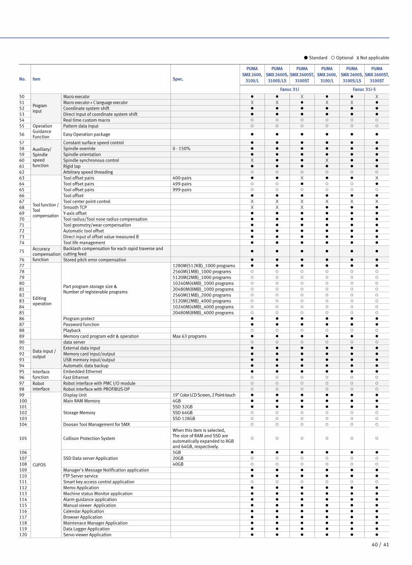
No. Item Spec.
PUMA SMX 2600,
3100/L
PUMA SMX 2600S,
3100S/LS
PUMA SMX 2600ST,
3100ST
PUMA SMX 2600,
3100/L
PUMA SMX 2600S,
3100S/LS
PUMA SMX 2600ST,
3100ST
Fanuc 31i Fanuc 31i-5
50
Programinput
Macro executor ● ● X ● ● X
51 Macro executor + C language executor X X ● X X ●
52 Coordinate system shift ● ● ● ● ● ●
53 Direct input of coordinate system shift ● ● ● ● ● ●
54 Real time custom macro ○ ○ ○ ○ ○ ○
55 Operation GuidanceFunction
Pattern data input ○ ○ ○ ○ ○ ○
56 Easy Operation package ● ● ● ● ● ●
57Auxiliary/Spindlespeed function
Constant surface speed control ● ● ● ● ● ●
58 Spindle override 0 - 150% ● ● ● ● ● ●
59 Spindle orientation ● ● ● ● ● ●
60 Spindle synchronous control X ● ● X ● ●
61 Rigid tap ● ● ● ● ● ●
62 Arbitrary speed threading ○ ○ ○ ○ ○ ○
63
Tool function / Toolcompensation
Tool offset pairs 400-pairs ● ● X ● ● X
64 Tool offset pairs 499-pairs ○ ○ ● ○ ○ ●
65 Tool offset pairs 999-pairs ○ ○ ○ ○ ○ ○
66 Tool offset ● ● ● ● ● ●
67 Tool center point control X X X X X X
68 Smooth TCP X X X ● ● ●
69 Y-axis offset ● ● ● ● ● ●
70 Tool radius/Tool nose radius compensation ● ● ● ● ● ●
71 Tool geometry/wear compensation ● ● ● ● ● ●
72 Automatic tool offset ● ● ● ● ● ●
73 Direct input of offset value measured B ● ● ● ● ● ●
74 Tool life management ● ● ● ● ● ●
75 Accuracycompensation function
Backlash compensation for each rapid traverse and cutting feed
● ● ● ● ● ●
76 Stored pitch error compensation ● ● ● ● ● ●
77
Editing operation
Part program storage size & Number of registerable programs
1280M(512KB)_1000 programs ● ● ● ● ● ●
78 2560M(1MB)_1000 programs ○ ○ ○ ○ ○ ○
79 5120M(2MB)_1000 programs ○ ○ ○ ○ ○ ○
80 10240M(4MB)_1000 programs ○ ○ ○ ○ ○ ○
81 20480M(8MB)_1000 programs ○ ○ ○ ○ ○ ○
82 2560M(1MB)_2000 programs ○ ○ ○ ○ ○ ○
83 5120M(2MB)_4000 programs ○ ○ ○ ○ ○ ○
84 10240M(4MB)_4000 programs ○ ○ ○ ○ ○ ○
85 20480M(8MB)_4000 programs ○ ○ ○ ○ ○ ○
86 Program protect ● ● ● ● ● ●
87 Password function ● ● ● ● ● ●
88 Playback ○ ○ ○ ○ ○ ○
89 Memory card program edit & operation Max 63 programs ● ● ● ● ● ●
90
Data input / output
data server ○ ○ ○ ○ ○ ○
91 External data input ● ● ● ● ● ●
92 Memory card input/output ● ● ● ● ● ●
93 USB memory input/output ● ● ● ● ● ●
94 Automatic data backup ● ● ● ● ● ●
95 Interface function
Embedded Ethernet ● ● ● ● ● ●
96 Fast Ethernet ○ ○ ○ ○ ○ ○
97 Robot interface
Robot interface with PMC I/O module ○ ○ ○ ○ ○ ○
98 Robot interface with PROFIBUS-DP ○ ○ ○ ○ ○ ○
99
CUFOS
Display Unit 19" Color LCD Screen, 2 Point-touch ● ● ● ● ● ●
100 Main RAM Memory 4GB ● ● ● ● ● ●
101Storage Memory
SSD 32GB ● ● ● ● ● ●
102 SSD 64GB ○ ○ ○ ○ ○ ○
103 SSD 128GB ○ ○ ○ ○ ○ ○
104 Doosan Tool Management for SMX ○ ○ ○ ○ ○ ○
105 Collison Protection System
When this item is selected, The size of RAM and SSD are automatically expanded to 8GB and 64GB, respectively.
○ ○ ○ ○ ○ ○
106SSD Data server Application
5GB ● ● ● ● ● ●
107 20GB ○ ○ ○ ○ ○ ○
108 40GB ○ ○ ○ ○ ○ ○
109 Manager's Message Notification application ● ● ● ● ● ●
110 FTP Server service ● ● ● ● ● ●
111 Smart key access control application ○ ○ ○ ○ ○ ○
112 Memo Application ● ● ● ● ● ●
113 Machine status Monitor application ● ● ● ● ● ●
114 Alarm guidance application ● ● ● ● ● ●
115 Manual viewer Application ● ● ● ● ● ●
116 Calendar Application ● ● ● ● ● ●
117 Browser Application ● ● ● ● ● ●
118 Maintenace Manager Application ● ● ● ● ● ●
119 Data Logger Application ● ● ● ● ● ●
120 Servo viewer Application ● ● ● ● ● ●
● Standard ◦ Optional X Not applicable
4140 /

Responding to Customers Anytime, Anywhere
AMERICA EUROPE
Global Sales and Service Support Network
Technical Center: Sales Support, Service Support, Parts Support
4Corporations
198Service Post
51Technical Centers
164Dealer Networks
3Factories
4342 /
PUMA
SMX
series
Product Overview
Basic information
Basic Structure
Main Units
Machine
Performance
CUFOS
Detailed
Information
Options
Diagrams
Specifications
Customer Support
Service
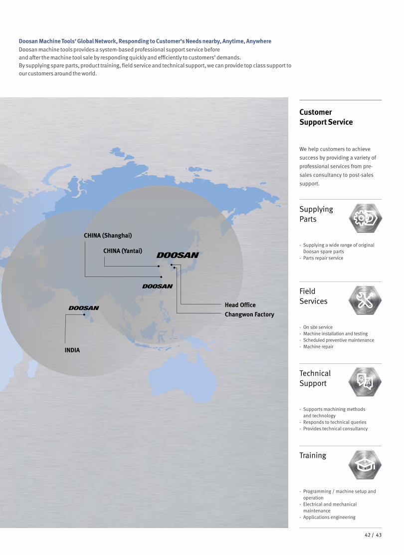
Doosan Machine Tools’ Global Network, Responding to Customer’s Needs nearby, Anytime, AnywhereDoosan machine tools provides a system-based professional support service before and after the machine tool sale by responding quickly and efficiently to customers’ demands.By supplying spare parts, product training, field service and technical support, we can provide top class support to our customers around the world.
We help customers to achieve
success by providing a variety of
professional services from pre-
sales consultancy to post-sales
support.
Customer Support Service
- On site service- Machine installation and testing- Scheduled preventive maintenance- Machine repair
Field Services
- Supports machining methods and technology
- Responds to technical queries- Provides technical consultancy
Technical Support
- Programming / machine setup and operation
- Electrical and mechanical maintenance
- Applications engineering
Training
- Supplying a wide range of original Doosan spare parts
- Parts repair service
Supplying Parts
CHINA (Yantai)
CHINA (Shanghai)
INDIA
Changwon Factory
Head Office
4342 /

*{ } Option
Major Specifications
PUMA SMX seriesDescription Unit
PUMA SMX2600
PUMA SMX3100/L
PUMA SMX 2600S/
ST
PUMA SMX3100S/
LS/ST
Chuck (Left spindle) inch 10 {12}* 12 {15}* 10 {12}* 12 {15}*
Chuck (Right spindle)
inch - 10 {12}*
Max. turning diameter
mm (inch)
660 (26.0)
Max. turning lengthmm
(inch)1540 (60.6)
[SMX3100L/LS : 2540(100)]
Spindle speed r/min 4000 3000Left / Right :
4000Left : 3000
Right : 4000
Motor power kW (Hp)26/22
(34.9/29.5)30/25
(40.2/33.5)26/22
(34.9/29.5)30/25
(40.2/33.5)
ver. EN 190613 SU
*For more details, please contact Doosan Machine Tools.
*The specifications and information above-mentioned may be changed without prior notice.
* Doosan Machine Tools Co., Ltd. is a subsidiary of MBK Partners. The trademark is used under a licensing agreement with Doosan Corporation,
the registered trademark holder.
There is a high risk or fire when using non-water-soluble cutting fluids, processing flammable materials, neglecting use coolants and modifying the machine without the consent of the manufacturer. Please check the SAFETY GUIDANCE carefully before using the machine.
Fire Safety Precautions
Head Office22F T Tower, 30, Sowol-ro 2-gil, Jung-gu,Seoul, Korea, 04637Tel +82-2-6972-0370 / 0350Fax +82-2-6972-0400
Doosan Machine Tools America19A Chapin Rd., Pine Brook, NJ 07058, U.S.A.Tel +1-973-618-2500 Fax +1-973-618-2501
Doosan Machine Tools EuropeEmdener Strasse 24, D-41540 Dormagen, Germany
Tel +49-2133-5067-100 Fax +49-2133-5067-111
Doosan Machine Tools IndiaNo.82, Jakkuar Village, Yelahanka Hobil, Bangalore-560064
Tel + 91-80-2205-6900 E-mail [email protected]
Doosan Machine Tools ChinaRoom 101,201,301, Building 39 Xinzhuan Highway No.258 Songjiang District,China Shanghai(201612)Tel +86 21-5445-1155Fax +86 21-6405-1472
www.doosanmachinetools.com
www.instagram.com/doosan_machinetools
www.facebook.com/doosanmachinetools
www.youtube.com/c/DoosanMachineToolsCorporation