Public Lighting Standards - Part 1 - 2018-10 - Cesena
66
Transnational Seminar - Module IV, Cesena/Italy, 23./24.10.2018 Public Lighting Standards - Part I (fundamentals) Prof. Axel Stockmar, LiTG e.V., Hannover University of Applied Sciences and Arts
Transcript of Public Lighting Standards - Part 1 - 2018-10 - Cesena

Transnational Seminar - Module IV, Cesena/Italy, 23./24.10.2018
Public Lighting Standards - Part I (fundamentals)
Prof. Axel Stockmar, LiTG e.V., Hannover University of Applied Sciences and Arts

TAKING COOPERATION FORWARD 2
Standardisation Bodies – the Network
ISO CIE
CEN LUX EUROPA
AFNORBSIDIN
AFESLLLiTG

TAKING COOPERATION FORWARD 3
The six Divisions of the International Commission on Illumination (CIE), 2018
Division 1 Vision & Colour
Division 2 Physical Measurement of Light and Radiation
Division 3 Interior Environment and Lighting Design
Division 4 Transportation and Exterior Applications
CIE 115:2010 “Lighting of roads for motor and pedestrian traffic”
Division 6 Photo-biology and Photo-chemistry
Division 8 Image Technology

TAKING COOPERATION FORWARD 4
Purpose of Road Lighting (CIE 115:2010)
The purpose of road lighting in general is to provide visual cues and to reveal obstacles, so that a safe vehicular operation is possible.
Fixed road lighting provides not only illumination on the road, but also on the nearby surroundings revealing extraneous objects and is opening up the field of view.
This is of particular importance in areas of high visual complexity where there may be different types of road users at the same time (motorists, cyclists, pedestrians, slow moving vehicles).
The lighting of residential areas is mainly provided to give safe passage to pedestrians, to reveal obstacles on their way, and to enable the recognition of people.

TAKING COOPERATION FORWARD 5
European Committee for Standardization
The European Committee for Standardization (CEN), a public standards organization, was founded in 1961 with the aim to promote the economy of the European Union (EU) in global trading, the welfare of European citizens and the environment by providing an efficient infrastructure to interested parties for the development, maintenance and distribution of coherent sets of standards and specifications.
European Standards can be used to enhance safety, security and performance, improve energy efficiency, and protect consumers, workers and the environment. European standards are developed by teams of experts who, nominated by their national standardization organisation, have particular knowledge of the specific sector or topic that is being addressed.
Standards are prepared by Technical Committees (TCs). Each Technical Committee has its own field of operation within which a work programme of identified standards is developed and executed.

TAKING COOPERATION FORWARD 6
CEN Technical Committee 169 ‘Light and Lighting’
One of the about 400 CEN Technical Bodies is the Technical Committee CEN/TC 169 ‘Light and Lighting’.
This committee is responsible for standards in the field of vision, photometry and colourimetry, involving natural and man-made optical radiation over the ultra-violet, the visible and the infrared regions of the spectrum, and application subjects covering all usages of light, indoors and outdoors, including environmental, energy and sustainability requirements and aesthetic and non-image forming biological aspects.
Altogether there are 14 working groups (WGs) dealing with the elaboration of standards covering the different aspects of light and lighting.
In the field of road lighting the most important working group is theCEN/TC 169 ‘Light and lighting’ and CEN/TC 226 ‘Road equipment’ joint working group ‘Road lighting’ (CEN/TC 169 WG12).

TAKING COOPERATION FORWARD 7
CEN/TC 169 ‘Light and Lighting’, 2018
WG1 Basic Terms and Criteria (EN 12665)
WG2 Lighting of Work Places (EN 12464-1/2, EN 13032-2)
WG3 Emergency Lighting (EN 1838, EN 13032-3)
WG4 Sports Lighting (EN 12193)
WG5 Road Lighting (EN 13201:2003)
WG6 Tunnel Lighting (CR 14380, EN 16276)
WG7 Photometry (EN 13032-1, EN 13032-4)
WG8 Photobiology (EN 14255, EN 16237)
WG9 Energy Performance of Buildings – Energy Requirements for Lighting (EN 15193)
WG10 Performance of Optical Materials for Luminaires (EN 16268)
WG11 Daylight (EN 17037)
WG12 TC169/226 JWG Road Lighting (TR/EN 13201, EN 13032-5)
WG13 Effect of Light on Human Beings
WG14 ErP Lighting Mandate Management Group

TAKING COOPERATION FORWARD 8
Joint Working Group ‘Road Lighting’
It is the scope of CEN/TC 169 Working Group 12 to specify lighting requirements for all classes of roads and road users which meet the needs of visual performance, comfort and safety.
It gives lighting values in terms of average luminances, average and minimum illuminances, uniformities, illuminance ratios, glare restrictions and the colour properties of the light sources to design and control road lighting installations and methods to calculate and measure these values.
The working group also provides details on how to measure and control the energy efficiency of road lighting installations.
Documents concerning road lighting should not be in contradiction to other reports or standards, in particular to those elaborated by working groups of CEN/TC 169 ‘Light and lighting’.

TAKING COOPERATION FORWARD 9
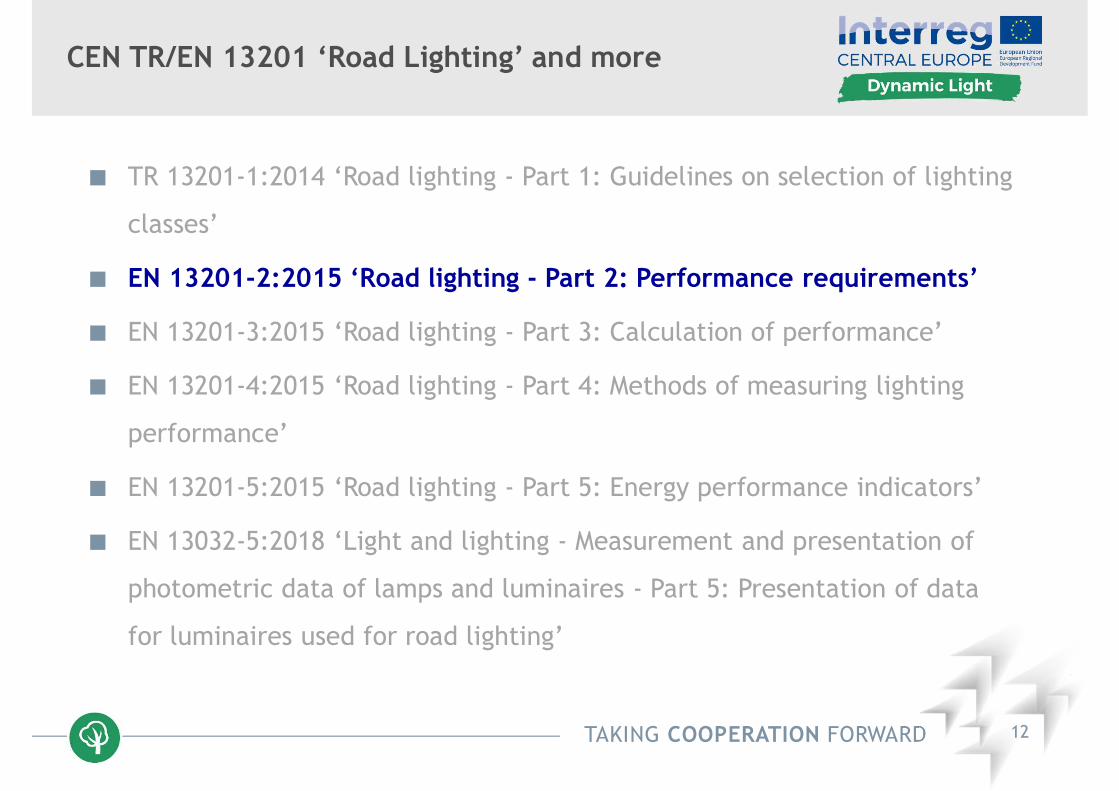
CEN TR/EN 13201 ‘Road Lighting’ and more
TR 13201-1:2014 ‘Road lighting - Part 1: Guidelines on selection of lighting
classes’
EN 13201-2:2015 ‘Road lighting - Part 2: Performance requirements’
EN 13201-3:2015 ‘Road lighting - Part 3: Calculation of performance’
EN 13201-4:2015 ‘Road lighting - Part 4: Methods of measuring lighting
performance’
EN 13201-5:2015 ‘Road lighting - Part 5: Energy performance indicators’
EN 13032-5:2018 ‘Light and lighting - Measurement and presentation of
photometric data of lamps and luminaires - Part 5: Presentation of data
for luminaires used for road lighting’

TAKING COOPERATION FORWARD 10
Main and Specific Objectives of the Interreg Project Dynamic Light (CE 452)
The main objective of this project is to make a shift from conventional municipal infrastructure planning towards a modern energy efficient and demand-orientated lighting design and better light and energy management.
The process itself presents smart solutions that will be developed and implemented as test pilots within the project lifetime.
They will significantly contribute to the reduction of CO2-emissions in local districts and regions and enhance the quality of stay.
The specific objectives comprise the promotion of user-accepted energy efficient lighting solutions by improving the quality of light according to social needs and to harmonize public lighting standards and norms.

TAKING COOPERATION FORWARD 11
Working Definition of Dynamic / Adaptive Lighting
(Urban) dynamic lighting is adaptive lighting, i.e. it is being provided
where and when it is needed depending on different variable conditions,
such as travelling speed, traffic volume and/or composition, ambient
luminances, weathers and other exterior factors in a way that it reduces
light pollution as well as energy consumption; beyond that it recognizes
varying human and social needs, such as aesthetics or feeling of safety, as
a basic concern and key factor in the design of adaptive public lighting
TAKING COOPERATION FORWARD 12
CEN TR/EN 13201 ‘Road Lighting’ and more
TR 13201-1:2014 ‘Road lighting - Part 1: Guidelines on selection of lighting
classes’
EN 13201-2:2015 ‘Road lighting - Part 2: Performance requirements’
EN 13201-3:2015 ‘Road lighting - Part 3: Calculation of performance’
EN 13201-4:2015 ‘Road lighting - Part 4: Methods of measuring lighting
performance’
EN 13201-5:2015 ‘Road lighting - Part 5: Energy performance indicators’
EN 13032-5:2018 ‘Light and lighting - Measurement and presentation of
photometric data of lamps and luminaires - Part 5: Presentation of data
for luminaires used for road lighting’
TAKING COOPERATION FORWARD 13
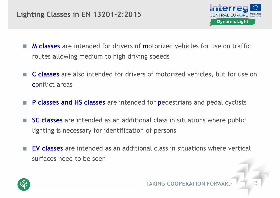
Lighting Classes in EN 13201-2:2015
M classes are intended for drivers of motorized vehicles for use on traffic
routes allowing medium to high driving speeds
C classes are also intended for drivers of motorized vehicles, but for use on
conflict areas
P classes and HS classes are intended for pedestrians and pedal cyclists
SC classes are intended as an additional class in situations where public
lighting is necessary for identification of persons
EV classes are intended as an additional class in situations where vertical
surfaces need to be seen

TAKING COOPERATION FORWARD 14
EN 13201-2:2015 ‘Road lighting - Part 2: Performance requirements’
In the European standard EN 13201-2:2015 ‘Road lighting - Part 2: Performance requirements’ a lighting class is defined by a set of photometric requirements aiming at the visual needs of certain road users in certain types of road areas under specified environmental conditions.
In this European standard which has to be implemented by the national standards organizations of the participating countries there are basically three more important sets of lighting classes described:
M classes for areas intended for motorized traffic
C classes for conflict areas
P classes for pedestrian and low speed areas

TAKING COOPERATION FORWARD 15
Lighting Classes M for Motorized Traffic
The controlling criteria for the lighting of roads for motorized traffic are the luminance level and uniformity of the carriageway, the illuminance level of the surrounds of the road, and the limitation of disability glare.
The most important (fixed or time-dependent) parameters to be considered are:
Speed Traffic volume Traffic composition Separation of carriageways Intersection density Parked vehicles Ambient luminance Difficulty of navigational task / Visual guidance / Traffic control

TAKING COOPERATION FORWARD 16
Lighting Classes M for Motorized Traffic
Lav average luminance Uow overall uniformity, wetUo overall uniformity FTI threshold incrementUl longitudinal uniformity REI edge illuminance ratio
Lighting class
Road surface luminance Threshold increment
Lighting of the surroundingsDry Wet
Lav in cd/m2 Uo Ul Uow fTI in % REI
M1 2.00 0.40 0.70
0.15
10 0.35
M2 1.50 0.40 0.70 10 0.35
M3 1.00 0.40 0.60 15 0.30
M4 0.75 0.40 0.60 15 0.30
M5 0.50 0.35 0.40 15 0.30
M6 0.30 0.35 0.40 20 0.30

TAKING COOPERATION FORWARD 17
Lighting Classes C for Conflict Areas
Conflict areas occur wherever vehicle streams intersect each other or run into areas frequented by pedestrians, cyclists, or other road users.
Areas showing a change in road geometry, such as a reduced number of lanes or a reduced lane or carriageway width (an area with measures of traffic calming), are also regarded as conflict areas.
Their existence results in an increased potential for collisions between vehicles, between vehicles and pedestrians, cyclists and other road users, and/or between vehicles and fixed objects.
The lighting of a conflict area should reveal the position of the kerbs and the road markings, the directions of the roads, the presence of pedestrians, other road users, and/or obstructions, and the movement of vehicles in the vicinity.

TAKING COOPERATION FORWARD 18
Lighting Classes C for Conflict Areas
C classes are mainly intended for use when conventions for road surface luminance calculations do not apply, e.g. viewing distances are less than 60 m.
The controlling criteria for the lighting of conflict areas are the average illuminance and the overall uniformity of the carriageway only or also of different other road areas.
In addition it could be necessary to calculate threshold increment for relevant observer positions and viewing directions in the conflict area (limitation of disability glare).

TAKING COOPERATION FORWARD 19
Lighting Classes C for Conflict Areas
Lighting class
Average illuminanceover whole of used
surface Eav in lx
Uniformity ofilluminance
Uo (E)
Threshold incrementfTI in %
C0 50 0.40 15
C1 30 0.40 15
C2 20 0.40 15
C3 15.0 0.40 20
C4 10.0 0.40 20
C5 7.50 0.40 20

TAKING COOPERATION FORWARD 20
Lighting Classes P for Pedestrian Areas
The lighting classes P are intended predominantly for pedestrians and
pedal cyclists for use on footways and cycle ways, but also for drivers of
motorized vehicles at low speed in pedestrian areas, on emergency or
parking lanes, and for other road areas lying separately or along a
carriageway of a traffic route or a residential road etc.
The visual tasks, sometimes vertical, i.e. recognition of faces, and needs
of pedestrians differ from those of drivers in many respects.
Speed of movement is generally much lower and relevant objects to be
seen are closer than those important for drivers of motorized vehicles.

TAKING COOPERATION FORWARD 21
Lighting Classes P for Pedestrian Areas
Lighting Class
Averagehorizontal
illuminanceEh,av in lx a
Minimumhorizontal
illuminanceEh,min in lx
Thresholdincrement
fTI in %
Additional requirementif facial recognition is necessary
Minimum verticalIlluminanceEv,min in lx
Minimumsemi-cylindrical
illuminanceEsc,min in lx
P1 15.0 3.00 20 5.0 3.0
P2 10.0 2.00 25 3.0 2.0
P3 7.50 1.50 25 2.5 1.5
P4 5.00 1.00 30 1.5 1.0
P5 3.00 0.60 30 1.0 0.6
P6 2.00 0.40 35 0.6 0.4
P7 --- --- --- --- ---a To provide for uniformity, the actual value of the maintained average illuminance
shall not exceed 1,5 times the average value indicated for the class.

TAKING COOPERATION FORWARD 22
CEN TR/EN 13201 ‘Road Lighting’ and more
TR 13201-1:2014 ‘Road lighting - Part 1: Guidelines on selection of lighting
classes’
EN 13201-2:2015 ‘Road lighting - Part 2: Performance requirements’
EN 13201-3:2015 ‘Road lighting - Part 3: Calculation of performance’
EN 13201-4:2015 ‘Road lighting - Part 4: Methods of measuring lighting
performance’
EN 13201-5:2015 ‘Road lighting - Part 5: Energy performance indicators’
EN 13032-5:2018 ‘Light and lighting - Measurement and presentation of
photometric data of lamps and luminaires - Part 5: Presentation of data
for luminaires used for road lighting’

TAKING COOPERATION FORWARD 23
Photometric Quantities to be calculated,EN 13201-3:2015
Horizontal (Eh), vertical (Ev), hemispherical (Ehs) and semi-cylindrical (Esc)
illuminances as maintained values
Road surface luminances (Lp) as maintained values
Overall (Uo) and longitudinal (Ul) uniformities
Threshold increments (TI) as initial values
Edge Illuminance Ratio (EIR)
TAKING COOPERATION FORWARD 24
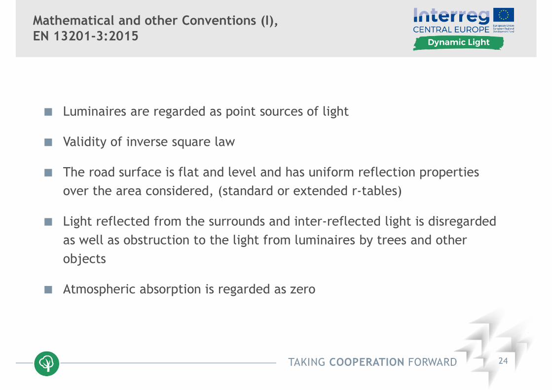
Mathematical and other Conventions (I),EN 13201-3:2015
Luminaires are regarded as point sources of light
Validity of inverse square law
The road surface is flat and level and has uniform reflection properties over the area considered, (standard or extended r-tables)
Light reflected from the surrounds and inter-reflected light is disregarded as well as obstruction to the light from luminaires by trees and other objects
Atmospheric absorption is regarded as zero

TAKING COOPERATION FORWARD 25
Mathematical and other Conventions (II),EN 13201-3:2015
Interpolation of luminous intensity distribution:
always linear for C 5 and 2.5
Note: The angular spacings should be reduced in case of luminous intensity distributions with great variations (LED).
Interpolation of standard or extended r-tables always linear
Observer (line of sight 1 below the horizontal) in the centre line of each lane for the calculation of L , Uo , Ul, and TI
All luminaires within the boundary of the r-tables to be included in the calculation

TAKING COOPERATION FORWARD 26
Mathematical and other Conventions (III),EN 13201-3:2015
Length of calculation field is equal to luminaire spacing S
Number N of calculation points along calculation field: S 30 m N = 10, S > 30 m S / N 3 m
Width of calculation field W is equal to the width of the carriageway
For the calculation of road surface luminances 3 calculation points per lane across, otherwiseW 4.5 m n = 3, W > 4.5 m W / n 1.5 m
The number of calculation points is not sufficient to show non-uniformitiescaused by luminous intensity distributions with great variations (LED).

TAKING COOPERATION FORWARD 27
Position of Calculation Points per Lane,EN 13201-3:2015
1 ... Edge of lane, 2 ... Last luminaire, 3 ... Field of calculation,4 ... Centre line of lane,5 ... First luminaire, 6 ... Observation direction, 7 ... Observer‘s longitudinal position

TAKING COOPERATION FORWARD 28
Factors Influencing the Degree of Glare,according to Publication CIE 112:1994
It is generally agreed that discomfort glare produced by an individual source depends on four parameters, i.e. the source luminance in the direction of the observer‘s eye, the solid angle subtended by the source at the observer‘s eye, the angular displacement of the source from the observer‘s line of sight, and the general filed luminance controlling the adaptation level of the observer‘s eye
According to the Holladay formula, the disability glare effect is described as an equivalent uniform luminance resulting from stray light in the eye which superimposes on the location of the vertical image, thus lowering the contrast. This equivalent veiling luminance depends mainly on two parameters, i.e. the illuminance on the observer‘s eye produced by the glare source in the plane perpendicular to the line of sight, and the angle between the centre of the glare source and the line of sight

TAKING COOPERATION FORWARD 29
Calculation of Veiling Luminances and ThresholdIncrements (I), EN 13201-3:2015
Observer in the centre line of each lane
Observer‘s eye at a height of 1.5 m above road level
First observer longitudinally at a distance of 2.75 ( H – 1.5 ) meters in front of the calculation field ( H ... Mounting height )
Luminaires above a screening plane, which is inclined at 20°to the horizontal, are excluded from the calculation
Calculation is repeated with the with the observer moved forward in increments of S / N
Summation is performed for the first luminaire in the direction of observation and the luminaires beyond, up to a distance of 500 m in each luminaire row, using Fry‘s formula with (1.5° 60°)

TAKING COOPERATION FORWARD 30
Calculation of Veiling Luminances and ThresholdIncrements (II), EN 13201-3:2015
Veiling luminance Lvk of pending luminaire k is calculated using either
when 1.5° < k 60°
or
when 0.1< k 1.5°
Ek initial illuminance produced by kth luminaire (lx)k angle between the line of sight and the centre of the kth luminaire (°)Ay age of observer in years
2k
k4
yvk 66,4
186,9EA
L
4y
2k
3k
kvk 62,51
510 AEL

TAKING COOPERATION FORWARD 31
Calculation of Veiling Luminances and ThresholdIncrements (III), EN 13201-3:2015
Constant k of veiling luminance / TI calculation formula as function of age

TAKING COOPERATION FORWARD 32
Calculation of Veiling Luminances and ThresholdIncrements (IV), CIE 30:1976
Having obtained the total veiling luminance of an installation the amount of disability glare can be found by calculating the threshold increment TI of an object which is in use to signify the visual task.
In road lighting the standard object is assumed to be 8‘ in angular size.
The threshold is determined by the adaptation luminance at the location at which the object has to be perceived.
At fair luminance uniformities of the road surface the adaptation luminance may be approximated by the average road surface luminance.
The relative threshold increment is expressed as the difference of the threshold under glare condition ΔLglare and its value without glare ΔL as:
%100
L
LLTI glare

TAKING COOPERATION FORWARD 33
Calculation of Veiling Luminances and ThresholdIncrements (V), Adaptive Lighting
Threshold increment as function of adaptation luminance fordifferent ratios R of veiling luminance to adaptation luminance

TAKING COOPERATION FORWARD 34
Calculation of Edge Illuminance Ratio (I),EN 13201-3:2015
The Edge Illuminance Ratio (REI) is defined as the average horizontal
illuminance on two longitudinal strips of equal width each adjacent to the
two edges of the carriageway, and lying off the carriageway ( E1 , E4 ),
divided by the average horizontal illuminance on two longitudinal strips of
equal width each adjacent to the edges of the carriageway, but lying on
the carriageway ( E2 , E3 )

TAKING COOPERATION FORWARD 35
Calculation of Edge Illuminance Ratio (II),EN 13201-3:2015
REI = E1 / E2 , REI = E4 / E3
5 ... Luminaire, 6 ... Edge of carriageway, 7 ... Obstruction,Ws ... width of strip always equal width of lane, [figure 16 b) from EN 13201-3]

TAKING COOPERATION FORWARD 36
Calculations and Results, EN 13201-3:2015
Average luminance, overall uniformity, and threshold increment have to be calculated for each observer position (in the centre line of each lane) considering the total width of the carriageway
Longitudinal uniformity is calculated for the centre line of each lane
As result is regarded the lowest average luminance (maintained value), the lowest overall uniformity, and the lowest longitudinal uniformity (calculated for the different observer positions)
As result is regarded the highest threshold increment (initial value) calculated for the different observer positions, the method has not been validated sufficiently yet for LED installations
As result is regarded the lowest of the two edge illuminance ratios

TAKING COOPERATION FORWARD 37
CEN TR/EN 13201 ‘Road Lighting’ and more
TR 13201-1:2014 ‘Road lighting - Part 1: Guidelines on selection of lighting
classes’
EN 13201-2:2015 ‘Road lighting - Part 2: Performance requirements’
EN 13201-3:2015 ‘Road lighting - Part 3: Calculation of performance’
EN 13201-4:2015 ‘Road lighting - Part 4: Methods of measuring lighting
performance’
EN 13201-5:2015 ‘Road lighting - Part 5: Energy performance indicators’
EN 13032-5:2018 ‘Light and lighting - Measurement and presentation of
photometric data of lamps and luminaires - Part 5: Presentation of data
for luminaires used for road lighting’

TAKING COOPERATION FORWARD 38
Photometric Quantities to be measured,EN 13201-4:2015
Horizontal Eh and vertical Ev illuminances; requiring
photometer head for measurement of planar illuminances,
also using dynamic measurement systems
Hemispherical Ehs and semi-cylindrical Esc illuminances;
requiring special purpose build photometer head
Road surface luminances Lp; requiring luminance meter with
suitable performance, also using dynamic measurement
systems including imaging devices

TAKING COOPERATION FORWARD 39
Non-photometric Measurements,EN 13201-4:2015
Geometric data; height of columns, length of outreach, orientation, tilt, and rotation in application of luminaires
Supply voltage; preferably using a recording voltmeter
Ambient temperature and humidity; at a height of 1.0 m above ground level (preferably at 30 minutes intervals)

TAKING COOPERATION FORWARD 40
Example of Report,EN 13201-4:2015, Annex H (informative)
General test information
Geometric data
Road surface data
Lamp and luminaire data
Electricity supply data
Environmental conditions
Condition of installation
Measuring devices data
Photometric measuring devices characteristics
Measurement grid
Light monitoring record
Specific information for dynamic measurements

TAKING COOPERATION FORWARD 41
CEN TR/EN 13201 ‘Road Lighting’ and more
TR 13201-1:2014 ‘Road lighting - Part 1: Guidelines on selection of lighting
classes’
EN 13201-2:2015 ‘Road lighting - Part 2: Performance requirements’
EN 13201-3:2015 ‘Road lighting - Part 3: Calculation of performance’
EN 13201-4:2015 ‘Road lighting - Part 4: Methods of measuring lighting
performance’
EN 13201-5:2015 ‘Road lighting - Part 5: Energy performance indicators’
EN 13032-5:2018 ‘Light and lighting - Measurement and presentation of
photometric data of lamps and luminaires - Part 5: Presentation of data
for luminaires used for road lighting’

TAKING COOPERATION FORWARD 42
EN 13201-5:2015 ‘Energy Performance Indicators’,Scope (I)
This part of the European Standard defines how to calculate the energyperformance indicators of road lighting installations using the power density indicator (PDI) DP and the annual energy consumption indicator(AECI) DE.
Power density indicator (DP) demonstrates the energy needed for a roadlighting installation, while it is fulfilling the relevant lighting requirements.
The annual energy consumption indicator (DE) determines the power consumption during a year, even if the lighting requirements changeduring the hours of darkness (adaptive lighting).

TAKING COOPERATION FORWARD 43
EN 13201-5:2015 ‘Energy Performance Indicators’,Scope (II)
As such, these indicators may be used for the comparison of the energyperformance of different road lighting solutions and technologies for thesame lighting project.
The energy performance of road lighting systems with different roadgeometries or different lighting requirements cannot be compared toeach other directly (?), as the energy performance is influenced by,among others, the geometry of the area to be lit as well as by thelighting requirements.
The power density indicator (DP) and the annual energy consumptionindicator (DE) apply to all traffic areas covered by the series oflighting classes M, C and P as defined in EN 13201-2:2015; theyshall be presented always together.

TAKING COOPERATION FORWARD 44
Power Density Indicator (PDI),EN 13201-5:2015
DP power density indicator in W/(lxm2) or in W/lm
P system power of the lighting installation used to light the relevantareas in W
Ei maintained average horizontal illuminance of the sub-area i in lx
Ai size of sub-area i lit by the lighting installation in m2
n number of sub-areas to be lit
ii
n
i
P
AE
PD
1

TAKING COOPERATION FORWARD 45
Annual Energy Consumption Indicator (AECI),EN 13201-5:2015
DE annual energy consumption indicator for a road lighting installation
in Wh/m2
Pj operational power associated with the jth period of operation in W
tj duration of jth period of operation profile when power Pj is consumed
in h
A size of the area lit by the same arrangement in m2
m number of periods with different operational power Pj
A
tP
Dj
m
jj
E
1

TAKING COOPERATION FORWARD 46
Installation luminous efficacy (I),EN 13201-5:2015, Annex B (informative)
In Annex B of EN 13201-5:2015 the installation luminous efficacy inst
is described as a measure to evaluate the energy efficiency
The installation luminous efficacy inst is defined as the minimum
luminous flux min needed to provide the minimum lighting level for
the specified area divided by the total average system power Ptotal
of the lighting installation
The minimum luminous flux min is given as average illuminance E
(according to the requirement of the appropriate lighting class) times
the size A of area to be considered
TAKING COOPERATION FORWARD 47
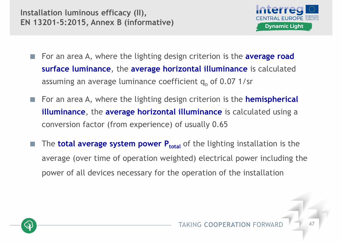
Installation luminous efficacy (II),EN 13201-5:2015, Annex B (informative)
For an area A, where the lighting design criterion is the average road
surface luminance, the average horizontal illuminance is calculated
assuming an average luminance coefficient qo of 0.07 1/sr
For an area A, where the lighting design criterion is the hemispherical
illuminance, the average horizontal illuminance is calculated using a
conversion factor (from experience) of usually 0.65
The total average system power Ptotal of the lighting installation is the
average (over time of operation weighted) electrical power including the
power of all devices necessary for the operation of the installation

TAKING COOPERATION FORWARD 48
CEN TR/EN 13201 ‘Road Lighting’ and more
TR 13201-1:2014 ‘Road lighting - Part 1: Guidelines on selection of
lighting classes’
EN 13201-2:2015 ‘Road lighting - Part 2: Performance requirements’
EN 13201-3:2015 ‘Road lighting - Part 3: Calculation of performance’
EN 13201-4:2015 ‘Road lighting - Part 4: Methods of measuring lighting
performance’
EN 13201-5:2015 ‘Road lighting - Part 5: Energy performance indicators’
EN 13032-5:2018 ‘Light and lighting - Measurement and presentation of
photometric data of lamps and luminaires - Part 5: Presentation of data
for luminaires used for road lighting’

TAKING COOPERATION FORWARD 49
Selection of an Appropriate Lighting Class,Parameters to be Considered
For the selection of an appropriate lighting class as well as for theapplication of adaptive lighting a number of various parameters areconsidered in the different technical reports or standards.
These parameters are generally related to:- the geometry of the area under consideration (fixed)- the traffic use of the area (time-dependent)- the influence of the surrounding environment (time-dependent)
The most comprehensive number of parameters to be taken intoaccount, covering the lighting classes M for motorized traffic,C for conflict areas, and P for pedestrian and low speed areas,can be found in the technical report CEN/TR 13201-1:2014.
In the different standards usually only a sub-set of these parameters is considered, in some cases with different names for the same influence.
TAKING COOPERATION FORWARD 50
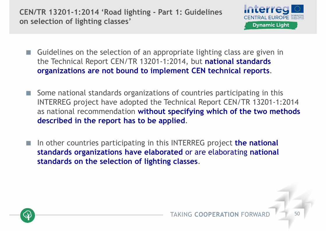
CEN/TR 13201-1:2014 ‘Road lighting - Part 1: Guidelines on selection of lighting classes’
Guidelines on the selection of an appropriate lighting class are given in the Technical Report CEN/TR 13201-1:2014, but national standards organizations are not bound to implement CEN technical reports.
Some national standards organizations of countries participating in this INTERREG project have adopted the Technical Report CEN/TR 13201-1:2014 as national recommendation without specifying which of the two methods described in the report has to be applied.
In other countries participating in this INTERREG project the national standards organizations have elaborated or are elaborating national standards on the selection of lighting classes.

TAKING COOPERATION FORWARD 51
Adaptive Lighting (CIE 115:2010)
The normal lighting class M, C, or P is selected using the most onerous values for the parameters to be considered, but the application of this class may not be justified during all hours of darkness.
Temporal changes in the parameters under consideration for the selected lighting class could allow an adaptation of the normal lighting level, usually by reducing the average luminance or illuminance.
The adapted lighting level or levels should be from a corresponding lighting class M, C, or P respectively.
Reducing the light output from every lamp of an installation using dimming techniques will not affect the uniformities, the object contrasts, and the glare control.
Reducing the average lighting level by switching off some luminaires will usually result in inadequate uniformities and possibly in excessivedisability glare.

TAKING COOPERATION FORWARD 52
Selection of a Lighting Class M,(CIE 115:2010, original proposal)
Parameter Options Weighting Value
SpeedVery high 1
High 0,5
Moderate 0
Traffic volume
Very high 1
High 0,5
Moderate 0
Low -0,5
Very low -1
Traffic compositionMixed with high percentage of non-motorized 2
Mixed 1
Motorized only 0
Separation of carriagewaysNo 1
Yes 0
Intersection densityHigh 1
Moderate 0
Parked vehiclesPresent 1
Not present 0
Ambient luminance
Very high 1
High 0,5
Moderate 0
Low -0,5
Very low -1
Visual guidance /traffic control
Poor 0,5
Moderate 0
Good -0,5

TAKING COOPERATION FORWARD 53
Selection of a Lighting Class M,(CEN/TR 13201-1:2014)
Parameter Options Description a Weighting Value VW a
Design speed or speed limit
Very high v ≥ 100 km/h 2
High 70 < v < 100 km/h 1
Moderate 40 < v ≤ 70 km/h -1
Low v ≤ 40 km/h -2
Traffic volume
Motorways, multilane routes Two lane routes High > 65 % of maximum capacity > 45 % of maximum capacity 1
Moderate 35 % - 65 % of maximum capacity 15 % - 45 % of maximum capacity 0
Low < 35 % of maximum capacity < 15 % of maximum capacity -1
Traffic composition
Mixed with high percentage of non-motorised
2
Mixed 1
Motorised only 0
Separation of carriageway
No 1
Yes 0
Junction densityIntersection/km Interchanges, distance between bridges, km
High > 3 < 3 1
Moderate ≤ 3 ≥ 3 0
Parked vehiclesPresent 1
Not present 0
Ambient luminosityHigh
shopping windows, advertisement expressions, sport fields, station areas, storage areas
1
Moderate normal situation 0
Low -1
Navigational taskVery difficult 2
Difficult 1
Easy 0
a The values stated in the column are an example. Any adaptation of the methodor more appropriate weighting values can be used instead, on the national level.

TAKING COOPERATION FORWARD 54
Alternative Method for Selection of a Lighting Class,(CEN/TR 13201-1:2014, Annex B)

TAKING COOPERATION FORWARD 55
Selection of a Lighting Class M, C or P,National Technical Reports / Standards
AT Standard O 1051:2017, based on CEN/TR 13201-1:2014
CR HRI CEN/TR 13201-1:2016-11-22
CZ CSN 13201-1:2007
DE revision of standard DIN 13201-1 in progress, based on roadcategories, expected in 2018
IT Standard UNI 11248:2016, based on road categories
PL PKN-CEN/TR 13201-1:2016-02
SL SIST-TP CEN/TR 13201-1:2015

TAKING COOPERATION FORWARD 56
Categorization of Types of Roadacc. to Italian Standard UNI 11248:2016

TAKING COOPERATION FORWARD 57
Road Layouts and Traffic Volumes associatedwith Types of Road acc. to UNI 11248:2016

TAKING COOPERATION FORWARD 58
Fixed and Variable Parameters / ExampleMain Road acc. to E DIN 13201-1:2018
Auswahlparameter Optionen/Auswahlmöglichkeit Wichtungswert VW
Geschwindigkeit>50 km/h 1
≤ 50km/h 0
Trennung der Richtungsfahrbahnen
Nein 1
ja 0
Zwischenwert
Variable Parameter für die adaptive Beleuchtung
Optionen/Auswahlmöglichkeit Wichtungswert VWZeitpunkt
t0 t1
VerkehrsaufkommenNormal 0
Gering -1
Verkehrsart Zusammensetzung
Gemischt, hoher Anteil nicht motorisiert 2
Gemischt 1
Nur motorisierter Verkehr 0
Leuchtdichte der Umgebung
Hoch 1
Mittel 0
Gering -1
Parkende Fahrzeugezulässig 1
nicht zulässig 0
Erhöhte AnforderungenVorhanden 1
Nicht vorhanden 0
Summe der Wichtungswerte Vws
Beleuchtungsklasse M = 6 − VWS

TAKING COOPERATION FORWARD 59
CEN TR/EN 13201 ‘Road Lighting’ and more
TR 13201-1:2014 ‘Road lighting - Part 1: Guidelines on selection of lighting
classes’
EN 13201-2:2015 ‘Road lighting - Part 2: Performance requirements’
EN 13201-3:2015 ‘Road lighting - Part 3: Calculation of performance’
EN 13201-4:2015 ‘Road lighting - Part 4: Methods of measuring lighting
performance’
EN 13201-5:2015 ‘Road lighting - Part 5: Energy performance indicators’
EN 13032-5:2018 ‘Light and lighting - Measurement and presentation of
photometric data of lamps and luminaires - Part 5: Presentation of data
for luminaires used for road lighting’

TAKING COOPERATION FORWARD 60
Introduction and Definitions,EN 13032-5:2018
The energy efficiency of a road lighting installation depends stronglyon the utilization factor road lighting
The utilization factor road lighting is defined as the ratio of theluminous flux received by one or more parallel strips along the roadto the sum of the individual total fluxes of the lamps / light sourcesof the installation
But in this European standard utilance is used in place of utilizationfactor because it can be applied to luminaires with replaceable ornon-replaceable lamps / light sources
The utilance road lighting is defined as the ratio of the luminous fluxreceived by one or more parallel strips along the road to the sum ofthe individual total fluxes of the luminaires of the installation

TAKING COOPERATION FORWARD 61
Basic Position of Reference Area relative to a Luminaire in a Row of Luminaires, EN 13032-5:2018
OV overhang (m); W width of reference area (m); H luminaire mounting height (m);t1, t2 transverse distances to limiting lines; B1, B2 angles of inclined limiting planes (°)
TAKING COOPERATION FORWARD 62
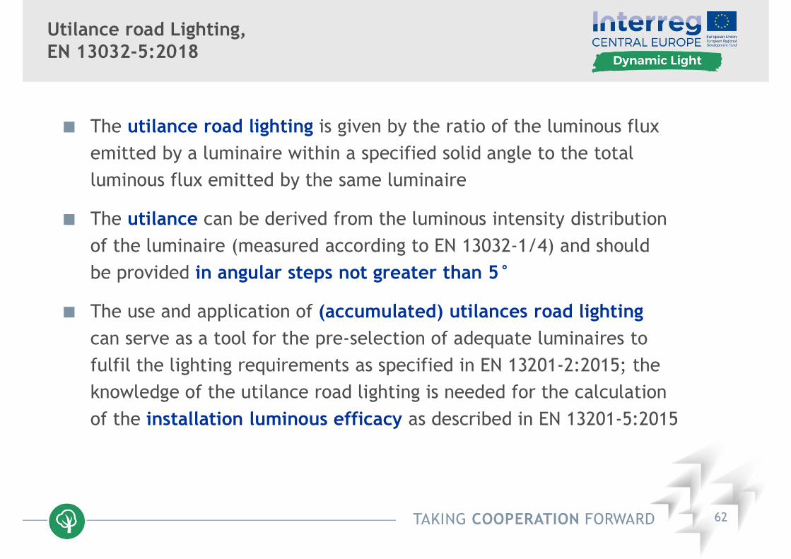
Utilance road Lighting,EN 13032-5:2018
The utilance road lighting is given by the ratio of the luminous fluxemitted by a luminaire within a specified solid angle to the totalluminous flux emitted by the same luminaire
The utilance can be derived from the luminous intensity distribution of the luminaire (measured according to EN 13032-1/4) and shouldbe provided in angular steps not greater than 5°
The use and application of (accumulated) utilances road lightingcan serve as a tool for the pre-selection of adequate luminaires tofulfil the lighting requirements as specified in EN 13201-2:2015; theknowledge of the utilance road lighting is needed for the calculationof the installation luminous efficacy as described in EN 13201-5:2015

TAKING COOPERATION FORWARD 63
Graphic Presentation of Utilances Road Lighting,EN 13032-5:2018
Utilances as function of plane angle B from -90° to 0° and from 0° to +90°
TAKING COOPERATION FORWARD 64
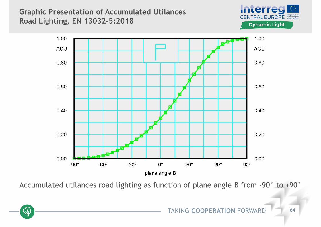
Graphic Presentation of Accumulated UtilancesRoad Lighting, EN 13032-5:2018
Accumulated utilances road lighting as function of plane angle B from -90° to +90°

TAKING COOPERATION FORWARD 65
Utilances Road Lighting for Strips E1 to E4, EdgeIlluminance Ratios E1/E2 and E4/E3, EN 13032-5:2018

TAKING COOPERATION FORWARD 66
Thank you very much for your attention!