Project 1 - SDC · PDF fileDrawing and Detailing with SolidWorks 2004 Drawing Template and...
83
Transcript of Project 1 - SDC · PDF fileDrawing and Detailing with SolidWorks 2004 Drawing Template and...


Drawing and Detailing with SolidWorks 2004 Drawing Template and Sheet Format
PAGE 1-1
Project 1
Drawing Template and Sheet Format
Below are the desired outcomes and usage competencies based on the completion of this Project. Note: The foundation of a SolidWorks drawing is the Drawing Template.
Project Desired Outcomes: Usage Competencies:
• C-Size Drawing Template.
• A-Size Drawing Template.
• Apply Document Properties to reflect the ASME
Y14 Engineering Drawing and Related Drawing
Practices.
• Understand the System Options and Document
Properties that affect the drawing and Drawing
Template.
• C-Size Sheet Format.
• Import an AutoCAD file as a Sheet Format.
• Insert SolidWorks System Properties and Custom
Properties.

Drawing Template and Sheet Format Drawing and Detailing with SolidWorks 2004
PAGE 1-2
Notes:

Drawing and Detailing with SolidWorks 2004 Drawing Template and Sheet Format
PAGE 1-3
Project 1 – Drawing Template and Sheet Format
Project Objective
Develop a C-size Drawing Template and C-size Sheet Format. Create an A-size Drawing Template.
On the completion of this project, you will be able to:
• Utilize the Command Manager, Toolbars, menus and user interface as they relate to the drawings.
• Understand the System Options and Document Properties as they relate to the drawings and templates.
• Modify the File Locations reference for the Templates.
• Comprehend the Document Properties referenced in the Drawing Template.
• Create an empty C-size Drawing Template. Propagate the settings to the drawing sizes.
• Import an AutoCAD drawing as a SolidWorks C-size Sheet Format.
• Combine the empty Drawing Template and Sheet Format to create a C-ANSI-MM Drawing Template.
• Develop Linked Notes to SolidWorks Properties and Custom Properties in the Sheet Format.
• Insert an OLE picture file into the Title block as a company logo.
• Create an A-ANSI-MM Drawing Template by combining information from the C-size Template and A-size Sheet Format.
In Project 1, utilize the following SolidWorks tools and commands.
SolidWorks Tools and Commands:
User Interface:
Command Manager
Control Area
Drawing Toolbar
Sketch Toolbar
Annotations Toolbar
Line Formats Toolbar
Main menu
Keyboard Shortcuts
Online help
Tools, Options System Options:
Drawings
Display Style
Tangent Edge
File Locations
Sheet Properties:
Sheet Name
Scale
Paper Size
Tools, Options Document Properties:
Detailing
Grid/Snap
Units
Line Font
Dimensioning
Standard
Edit Sheet/Edit Sheet Format
Document Properties, Detailing:
Dimensions
Notes
Arrows
Virtual Sharps
Annotation
Display
Annotation Font
Tables
View Labels
Properties:
System Properties
Custom
User defined
Linked Notes
View Properties
DXF/DWG Import
OLE Picture File
File, Save As, Drawing Template
File, Save Sheet Format

Drawing Template and Sheet Format Drawing and Detailing with SolidWorks 2004
PAGE 1-4
Project Overview
Your responsibilities as the designer include developing drawings that adhere to the ASME Y14 American National Standard for Engineering Drawing and Related Documentation Practices.
The foundation for a SolidWorks drawing is the Drawing Template. Drawing size, drawing standards, units and other properties are defined in the Drawing Template.
Sheet Formats contain the following: border, title block, revision block, company name, logo, SolidWorks Properties and Custom Properties.
You are under time constraints to complete the project. Conserve drawing time. Create a custom Drawing Template and Sheet Format.
Perform the following tasks in this Project:
• Modify Document Properties and create an empty C-size Drawing Template.
• Import an AutoCAD drawing and save the drawing as a C-size Sheet Format.
• Add System Properties and Custom Properties to the Sheet Format.
• Combine the empty Drawing Template and imported the Sheet Format to create the C-ANSI-MM Drawing Template.
• Generate an empty A-size Drawing Template.
• Modify an existing SolidWorks A-size Sheet Format.
• Create an A-ANSI-MM Drawing Template.
FORMAT-C-ACAD.DWG C-FORMAT.SLDDRT
C-SIZE-ANSI-MM-EMPTY.DRWDOT C-FORMAT.SLDDRT
A-SIZE-ANSI-MM-EMPTY.DRWDOT A-FORMAT.SLDDRT
C-ANSI-MM.DRWDOT
A-ANSI-MM.DRWDOT
AutoCAD Sheet Format
Empty C Sheet Format
Drawing
Template
Empty A Sheet Format
Drawing
Template
Empty C
Drawing
Template C-SIZE-ANSI-MM-EMPTY.DRWDOT
Drawing and Detailing with SolidWorks 2004 Drawing Template and Sheet Format
PAGE 1-5
Engineering Drawing and Related Documentation Practices
Drawing Templates in this section are based on the American Society of Mechanical Engineers ASME Y14 American National Standard for Engineering Drawing and Related Documentation Practices.
These standards represent the drawing practices used by U.S. industry. The ASME Y14 practices supersede the American National Standards Institute ANSI standards.
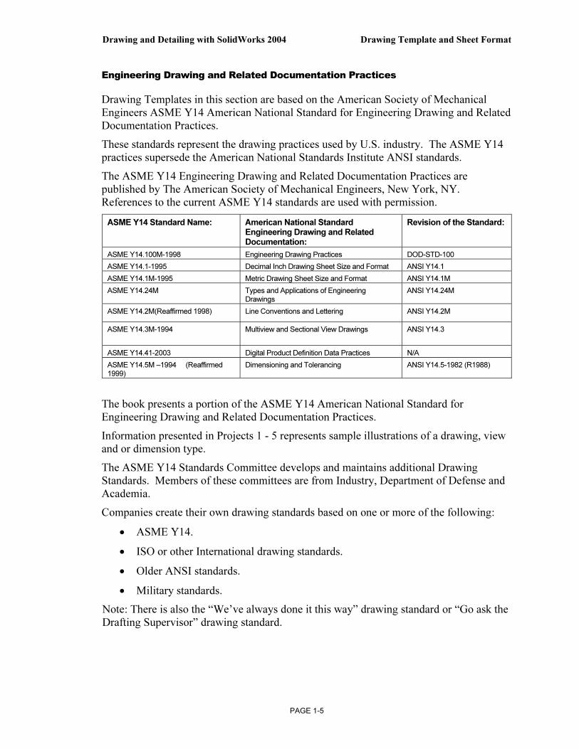
The ASME Y14 Engineering Drawing and Related Documentation Practices are published by The American Society of Mechanical Engineers, New York, NY. References to the current ASME Y14 standards are used with permission.
ASME Y14 Standard Name: American National Standard Engineering Drawing and Related Documentation:
Revision of the Standard:
ASME Y14.100M-1998 Engineering Drawing Practices DOD-STD-100
ASME Y14.1-1995 Decimal Inch Drawing Sheet Size and Format ANSI Y14.1
ASME Y14.1M-1995 Metric Drawing Sheet Size and Format ANSI Y14.1M
ASME Y14.24M Types and Applications of Engineering Drawings
ANSI Y14.24M
ASME Y14.2M(Reaffirmed 1998) Line Conventions and Lettering ANSI Y14.2M
ASME Y14.3M-1994
Multiview and Sectional View Drawings ANSI Y14.3
ASME Y14.41-2003 Digital Product Definition Data Practices N/A
ASME Y14.5M –1994 (Reaffirmed 1999)
Dimensioning and Tolerancing ANSI Y14.5-1982 (R1988)
The book presents a portion of the ASME Y14 American National Standard for Engineering Drawing and Related Documentation Practices.
Information presented in Projects 1 - 5 represents sample illustrations of a drawing, view and or dimension type.
The ASME Y14 Standards Committee develops and maintains additional Drawing Standards. Members of these committees are from Industry, Department of Defense and Academia.
Companies create their own drawing standards based on one or more of the following:
• ASME Y14.
• ISO or other International drawing standards.
• Older ANSI standards.
• Military standards.
Note: There is also the “We’ve always done it this way” drawing standard or “Go ask the Drafting Supervisor” drawing standard.

Drawing Template and Sheet Format Drawing and Detailing with SolidWorks 2004
PAGE 1-6
File Management
File management organizes parts, assemblies and drawings. File management is utilized to organize Drawing Templates and Sheet Formats.
Why do you require file management? Answer: Organize documents. A top level assembly necessitates hundreds or even thousands of drawings to document its parts and sub-assemblies. Drawings utilize various Drawing Templates and Sheet Formats.
Parts, assemblies and drawings are distributed between team members to conserve development time. Design changes occur frequently in the development process. How do you manage and control changes? Answer: Through file management. File management is a very important tool in the development process.
Utilize file folders to organize projects, vendor components, templates and libraries.
The documents required to complete the projects in Drawing and Detailing with SolidWorks 2004 are only available Online at www.schroff1.com.
Activity: File Management
Download the 2004drwparts zip folder from www.schroff1.com. 1) Enter www.schroff1.com from your web browser.
2) Click the hypertext: Drawing and Detailing with SolidWorks 2004. Follow the instructions on the web page. The zip file, 2004drwparts is downloaded.
3) Double-click 2004drwparts.zip to unzip the file.
4) Extract the DRAWING-W-SOLIDWORKS folder to My Documents.
5) Right-click My Documents\DRAWING-W-SOLIDWORKS folder.
6) Click Properties.
7) Uncheck Read Only.
8) Click Apply Changes to folders, subfolders and files.
9) Click OK two times.
The DRAWING-W-SOLIDWORKS folder contains multiple folders.
Store project Drawing Templates in the MY-TEMPLATES file folder. Store project Sheet Formats in the MY-SHEETFORMATS folder.

Drawing and Detailing with SolidWorks 2004 Drawing Template and Sheet Format
PAGE 1-7
Default Drawing Template, Sheet Format and Sheet Size
The foundation of a SolidWorks drawing is the Drawing Template.
Drawing sheet size, drawing standards, company information, manufacturing and or assembly requirements; units, layers, line styles and other properties are defined in the Drawing Template.
The Sheet Format is incorporated into the Drawing Template. The Sheet Format contains the following; sheet border, title block and revision block information, company name and or logo information, Custom Properties and SolidWorks Properties.
SolidWorks starts with a default Drawing Template, Drawing.drwdot. The default Drawing Template is located in the \SolidWorks\Data\Templates folder. SolidWorks is the name of the installation folder.
New SolidWorks Document
The Templates folder corresponds to the Templates tab displayed in the New SolidWorks Document dialog box. The List Details option displays the full Name, Size and Modified date.
Default Templates in Templates folder.
Drawing Template and Sheet Format Drawing and Detailing with SolidWorks 2004
PAGE 1-8
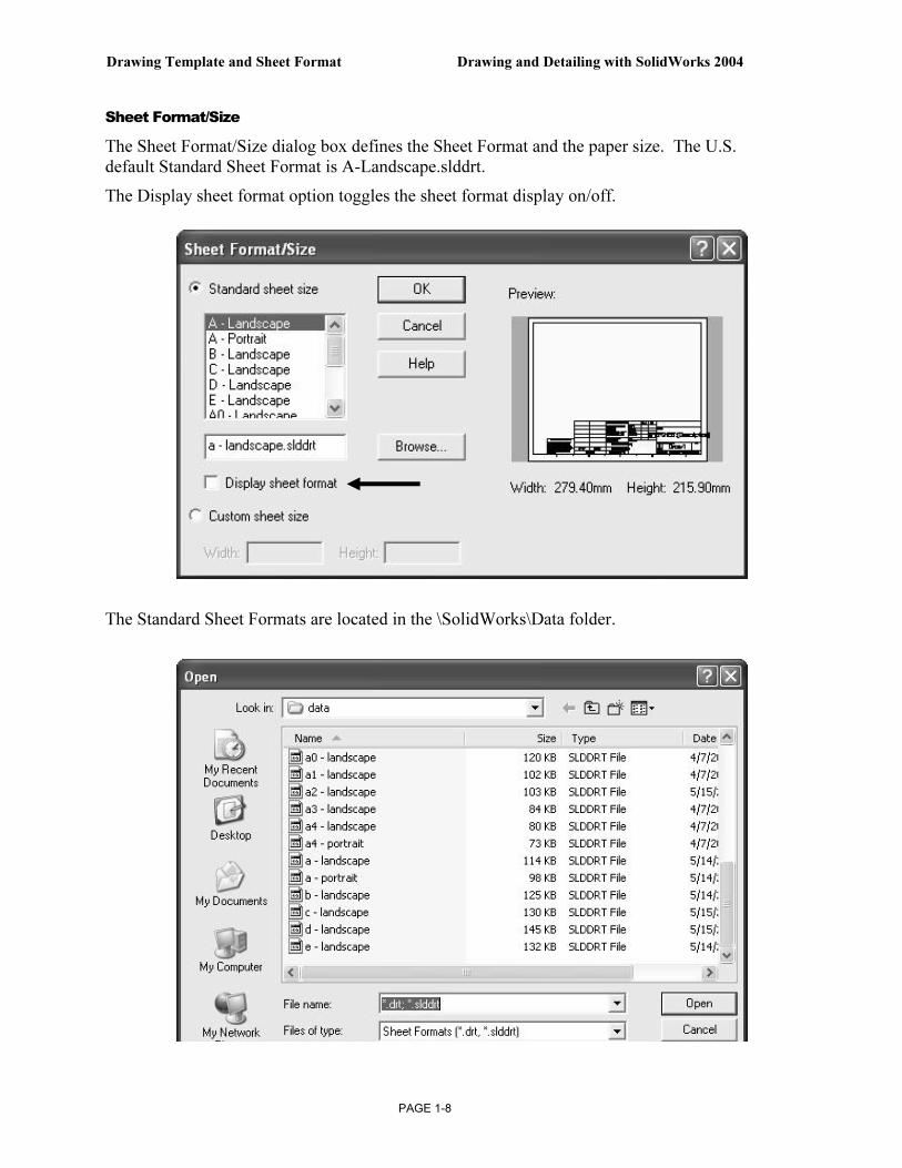
Sheet Format/Size
The Sheet Format/Size dialog box defines the Sheet Format and the paper size. The U.S. default Standard Sheet Format is A-Landscape.slddrt.
The Display sheet format option toggles the sheet format display on/off.
The Standard Sheet Formats are located in the \SolidWorks\Data folder.

Drawing and Detailing with SolidWorks 2004 Drawing Template and Sheet Format
PAGE 1-9
ASME Y14.1 Drawing Sheet Size and Format
There are two ASME standards that define sheet size and format. They are: ASME Y14.1-1995 Decimal Inch Drawing Sheet Size and Format and the ASME Y14.1M-1995 Metric Drawing Sheet Size.
Drawing Size refers to the physical paper size used to create the drawing. The most common paper size in the U.S. is the A size: (8.5in. x 11in.).
The most common paper size internationally is the A4 size: (210mm x 297mm).
The ASME Y14.1-1995 and ASME Y14.1M-1995 standards contain both a horizontal and vertical format for A and A4 size respectively.
The corresponding SolidWorks format is Landscape for horizontal and Portrait for vertical.
SolidWorks predefines U.S. drawing sizes A through E.
Drawing sizes F, G, H, J & K utilize the Custom sheet size option. Enter values for Width and Height.
SolidWorks predefines metric drawing sizes A4 through A0.
Metric roll paper sizes utilize the Custom sheet size option.
The ASME Y14.1-1995 Inch Drawing and Decimal ASME Y14.1M-1995 Metric Sheet Size standard are as follows:
Drawing Size:
“Physical Paper”
Size in inches:
Vertical Horizontal
Drawing Size:
“Physical Paper”
Size in Millimeters:
Vertical Horizontal
A horizontal (landscape) 8.5 11.0 A0 841 1189
A vertical (portrait) 11.0 8.5 A1 594 841
B 11.0 17.0 A2 420 594
C 17.0 22.0 A3 297 420
D 22.0 34.0 A4 horizontal (landscape) 210 297
E 34.0 44.0
F 28 40
A4 vertical (portrait) 297 210
G, H, J and K apply to roll sizes, User Defined
Caution should be used when sending electronic drawings between U.S. and international colleagues. Drawing paper sizes will vary.
A-Landscape (Default)
11″ x 8.5″

Drawing Template and Sheet Format Drawing and Detailing with SolidWorks 2004
PAGE 1-10
Example: An A-size (11in. x 8.5in.) drawing (280mm x 216mm) does not fit a A4 metric drawing (297mm x 210mm). Use a larger paper size or scale the drawing using the printer setup options.
Start a new session of SolidWorks. Create a new drawing with the default Drawing Template. Utilize C paper size with no sheet format displayed.
The sheet border defines the C drawing size: 22in. x 17in, (558.80mm x 431.80mm). A new Graphics window displays the C-Landscape Drawing, named Draw1.
Landscape indicates that the larger dimension is along the horizontal. A-Portrait and A4-Portrait indicates that the larger dimension is along the vertical.
Activity: Default Drawing Template
Start a SolidWorks session.
10) Click Start .
11) Click Programs.
12) Click the SolidWorks folder.
13) Click the SolidWorks application.
Select the Default Drawing Template.
14) Click New . Double-click the Drawing icon.
Select an empty C-Landscape sheet size. 15) Select C-Landscape from the
Standard sheet size drop down list.
16) Uncheck Display sheet format.
17) Click OK.
Exit the Model View.
18) Click Cancel from the ModelView PropertyManager.
Landscape Portrait

Drawing and Detailing with SolidWorks 2004 Drawing Template and Sheet Format
PAGE 1-11
User Interface
The User Interface combines the CommandManager, toolbars, menu options, commands, Online help, cursor feedback and keyboard shortcuts. Review the default options in the CommandManager.
CommandManager and Control Area
The Control Area of the CommandManager displays the Drawings, Sketch and Annotations toolbars. The Drawings toolbar is enabled by default.
The Model View PropertyManager is displayed when the Start command when creating new drawing option is checked.
Note: If the CommandManager is not displayed, right-click in the gray area of the Main menu and check the CommandManager option.
Control Area Drawings Toolbar
Drawing Template and Sheet Format Drawing and Detailing with SolidWorks 2004
PAGE 1-12
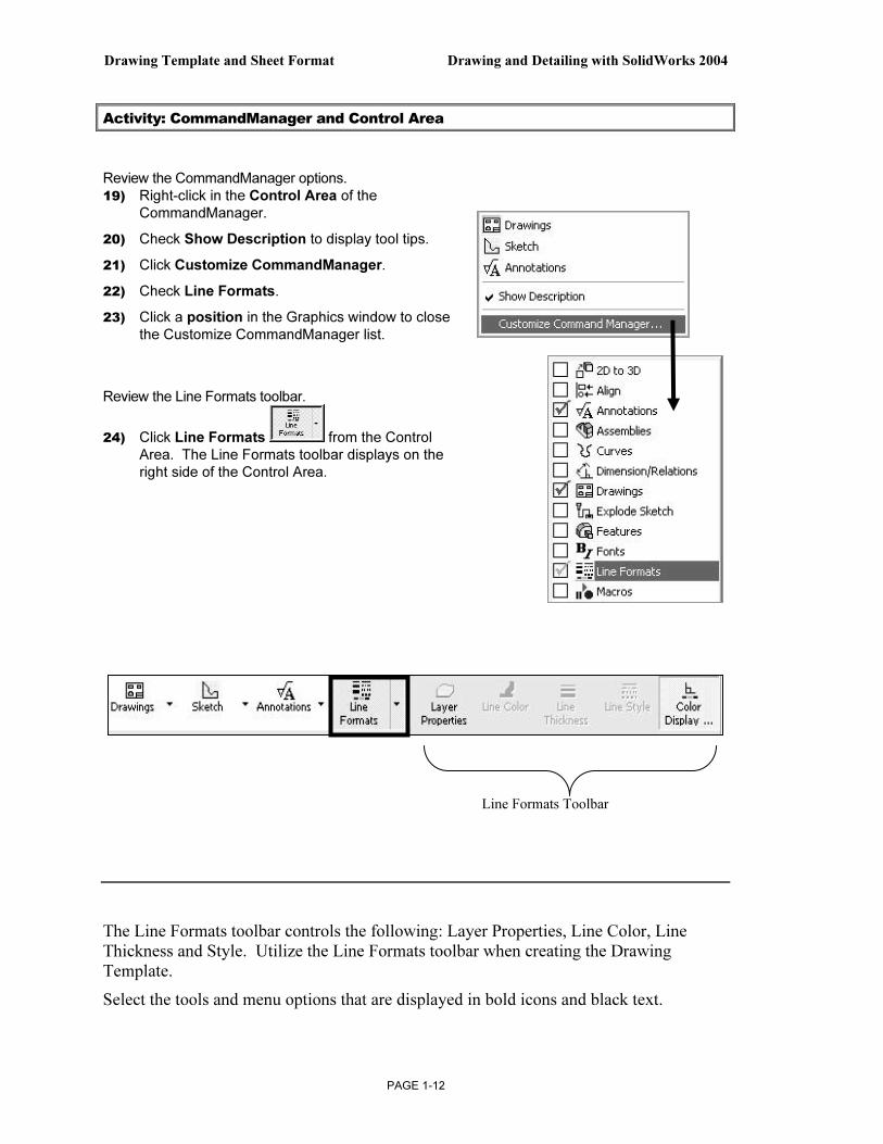
Activity: CommandManager and Control Area
Review the CommandManager options. 19) Right-click in the Control Area of the
CommandManager.
20) Check Show Description to display tool tips.
21) Click Customize CommandManager.
22) Check Line Formats.
23) Click a position in the Graphics window to close the Customize CommandManager list.
Review the Line Formats toolbar.
24) Click Line Formats from the Control Area. The Line Formats toolbar displays on the right side of the Control Area.
The Line Formats toolbar controls the following: Layer Properties, Line Color, Line Thickness and Style. Utilize the Line Formats toolbar when creating the Drawing Template.
Select the tools and menu options that are displayed in bold icons and black text.
Line Formats Toolbar
Drawing and Detailing with SolidWorks 2004 Drawing Template and Sheet Format
PAGE 1-13
The Tools and menu options that are displayed in gray are called grayed-out. The gray icon or text cannot be selected. Additional information is required for these options.
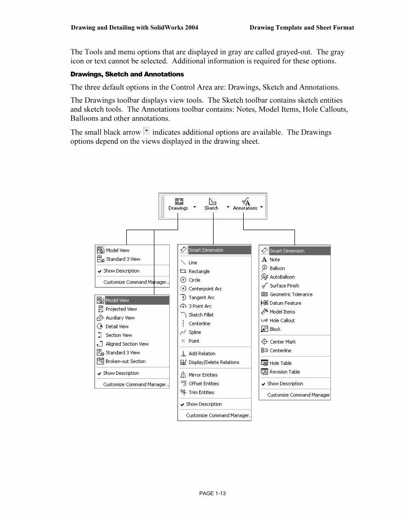
Drawings, Sketch and Annotations
The three default options in the Control Area are: Drawings, Sketch and Annotations.
The Drawings toolbar displays view tools. The Sketch toolbar contains sketch entities and sketch tools. The Annotations toolbar contains: Notes, Model Items, Hole Callouts, Balloons and other annotations.
The small black arrow indicates additional options are available. The Drawings options depend on the views displayed in the drawing sheet.
Drawing Template and Sheet Format Drawing and Detailing with SolidWorks 2004
PAGE 1-14
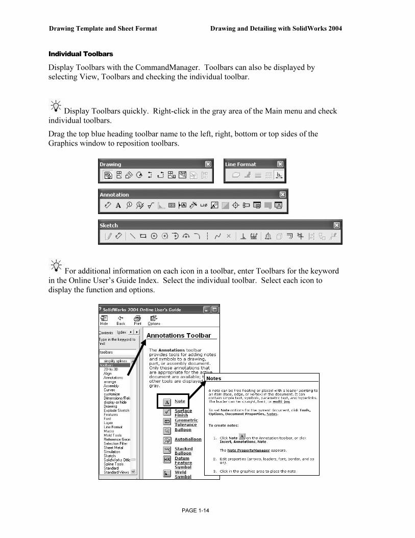
Individual Toolbars
Display Toolbars with the CommandManager. Toolbars can also be displayed by selecting View, Toolbars and checking the individual toolbar.
Display Toolbars quickly. Right-click in the gray area of the Main menu and check individual toolbars.
Drag the top blue heading toolbar name to the left, right, bottom or top sides of the Graphics window to reposition toolbars.
For additional information on each icon in a toolbar, enter Toolbars for the keyword in the Online User’s Guide Index. Select the individual toolbar. Select each icon to display the function and options.

Drawing and Detailing with SolidWorks 2004 Drawing Template and Sheet Format
PAGE 1-15
Main Menu
Access commands through the Main menu. The small black arrow indicates additional information is available.
SolidWorks Online User’s Guide – Online Help
The SolidWorks Online User’s Guide is divided into multiple sections. Utilize the Drawings and Detailing section in the Help, SolidWorks Help Topics, Contents.
The Additional information icon indicates that On-line help is available.
Additional User Interface Options
The right mouse button displays additional options and commands in the Graphics window.
The CommandManager, Toolbars, Pull-down menus, pop-up menus and keyboard commands are customizable.

Drawing Template and Sheet Format Drawing and Detailing with SolidWorks 2004
PAGE 1-16
Keyboard Shortcuts
Customize the keyboard to create Shortcut Keys for the Planes, Temporary Axis and Origins. Shortcut Keys conserve design time.
Activity: Keyboard Shortcuts
Customize the keyboard. 25) Click Tools, Customize.
26) Click the Keyboard tab.
27) Select View for Categories.
28) Select Planes for Commands.
29) Click a position inside the Press new shortcut key box.
30) Enter P for new shortcut key.
31) Click Assign.
32) Click OK.
The Shortcut Key, P is displayed next to the Planes option in the View menu. Create Short Cut Keys for Temporary Axes and the Origins as an exercise. The T and O Short Cut keys are utilized throughout the text.
Cursor Feedback
The cursor has an important role in the SolidWorks User Interface. The cursor provides feedback for the Sheet and View entities.
The cursor feedback displays the Sheet icon and lists the Sheet Name when the mouse pointer is located inside the sheet boundary.
The right mouse button displays command options based on the selected entity in the Graphics window.

Drawing and Detailing with SolidWorks 2004 Drawing Template and Sheet Format
PAGE 1-17
More Information
Additional details on Drawing Templates, Sheet Formats and the Drawing User Interface are available in Online help.
Keywords: Filename extensions (sheet formats), files(locations), files (new), new(drawing document), sheet formats, sheet properties, paper(size), CommandManager, Drawings, Toolbars (drawings, sketch, annotations, line formats) and keyboard (shortcuts).
Utilize the Appendix to review cursor feedback symbols in the drawing sheet and view.
Review
The project you are working on will produce hundreds of drawings. You are required to create Drawing Templates and Sheet Formats.
File management organizes SolidWorks documents into folders. Drawing Templates were stored in the MY-TEMPLATES folder. Sheet Formats were stored in the MY-SHEETFORMATS folder.
You reviewed the options for the Sheet format/size dialog box for the default Drawing Template. You created a new drawing with no Sheet Format. The empty drawing will become your Drawing Template.
The CommandManager, toolbars, menus and keyboard shortcuts are part of the SolidWorks User Interface. You reviewed the tools in the Drawings, Sketch, Annotations and Line Formats toolbars.
Sheet Properties
Sheet Properties display properties of the selected sheet. Sheet Properties define the following: Name of the Sheet, Sheet Scale, Type of Projection (First angle or Third angle), Sheet Format, Sheet Size, View label and Datum label.
The Sheet Format and Sheet Size are set in the default Drawing Template. Review the Sheet Properties. The Standard sheet size option is grayed out.
The Sheet Format file extension is .drt. The Sheet Format option is grayed out.
The C Paper size, width and height dimensions are listed under the Custom sheet size option.

Drawing Template and Sheet Format Drawing and Detailing with SolidWorks 2004
PAGE 1-18
Activity: Sheet Properties
Display the Sheet Properties. 33) Right-click in the sheet
boundary .
34) Click Properties. The Sheet Setup Properties are displayed.
Review the Sheet Properties. 35) Click OK.
The Sheet Name is Sheet1. The FeatureManager and Sheet tab display the Sheet Name.
The Sheet Scale is 1:1.
The Sheet Format box displays *.drt.
The Preview box contains no Sheet Format.
Custom sheet size is 22in x 17in (558.80mm x 431.80mm).
Third Angle and First Angle projection schemes are developed in Project 2. Third Angle projection is primarily used in the United States.
Drawing and Detailing with SolidWorks 2004 Drawing Template and Sheet Format
PAGE 1-19
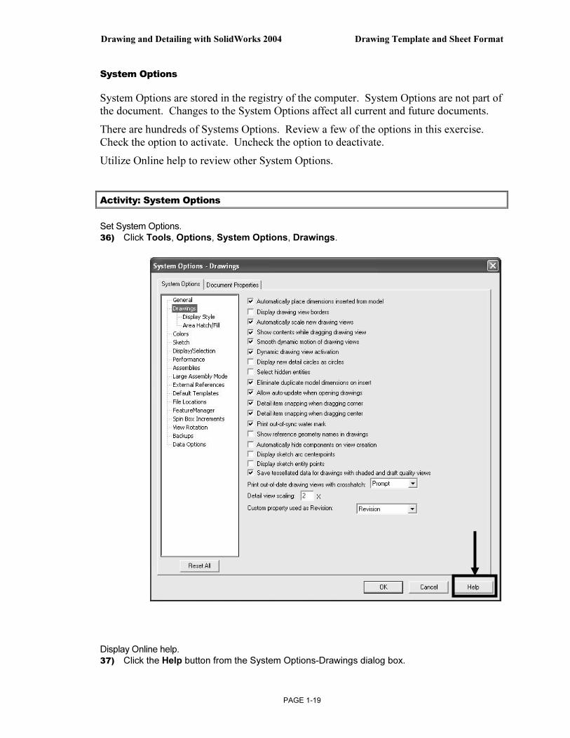
System Options
System Options are stored in the registry of the computer. System Options are not part of
the document. Changes to the System Options affect all current and future documents.
There are hundreds of Systems Options. Review a few of the options in this exercise.
Check the option to activate. Uncheck the option to deactivate.
Utilize Online help to review other System Options.
Activity: System Options
Set System Options.
36) Click Tools, Options, System Options, Drawings.
Display Online help.
37) Click the Help button from the System Options-Drawings dialog box.

Drawing Template and Sheet Format Drawing and Detailing with SolidWorks 2004
PAGE 1-20
Review each Drawing option. 38) Drag the Scroll bar
downward.
39) Minimize the Help window.
Help is accessible through the following:
• Help button.
• F1 key.
• Main menu.
• icon.
The quickest way to access Online help is to use the Help button from a
dialog box or from the PropertyManager. You do not have to spell or search for the topic when using these icons.

Drawing and Detailing with SolidWorks 2004 Drawing Template and Sheet Format
PAGE 1-21
Drawings, Display Style
Control the model display. SolidWorks has two Systems Options that control display. They are:
1. Display Style.
2. Tangent edge.
Review the Display Style options for a new drawing.
Review the Tangent edge options for a new view.
Control the options through the default settings or the individual drawing view.
Activity: Display Style
Set the Default Display Style. 40) Click Display Style below the
Drawings text.
41) Click Hidden lines removed for the Display style for the new views option.
42) Click Visible for the Default Tangent edges in the new views option.
Visible Use Font Removed
Tangent Edges
Hidden Lines Removed Shaded
Wireframe Hidden Lines Visible

Drawing Template and Sheet Format Drawing and Detailing with SolidWorks 2004
PAGE 1-22
File Locations
System Options, File Locations and the Document Templates option determines the path to locate a custom Drawing Templates. Add the MY-TEMPLATES folder to the File Locations. The folder listed in the Document Templates option determines the tabs displayed in the New SolidWorks Document dialog box.
Activity: File Locations
Set File Locations for Drawing Templates. 43) Click File Locations from
the System Options tab.
44) Select Document Templates from the Show Folders for Drop down list.
45) Click the Add button.
46) Click Browse.
47) Select the DRAWING-W-SOLIDWORKS\MY-TEMPLATES folder.
48) Click OK two times.
Note: The MY-TEMPLATES tab appears in the New SolidWorks Drawing dialog box.
The MY-TEMPLATES tab is not displayed if the folder is empty.
The System Option, File Locations list determines the order of the tabs.
Save the Drawing Templates to the MY-TEMPLATES folder.

Drawing and Detailing with SolidWorks 2004 Drawing Template and Sheet Format
PAGE 1-23
Document Properties
Document Properties apply to the current document. Set the following: Detailing options, Grid/Snap, Units, Line Fonts and Image Quality in Document Properties.
When the current document is saved as a template, the current parameters are stored with the template.
New documents that utilize the same template contain the stored parameters.
Conserve drawing time. Set the Document Properties in the Drawing Template.
Document Properties options contain hundreds of parameters. Examples are addressed in this section. Explore other parameters through Online help.
There are numerous text styles and sizes available in SolidWorks. Companies develop drawing format standards and use specific text height for Metric and English drawings.
The ASME Y14.2M-1992(R1998) standard lists the following: lettering, arrowhead, line conventions and lettering conventions for engineering drawings and related documentation practices.
Font
Century Gothic is the default SolidWorks font.
Create an assessment page to test that your Printer/Plotter drivers support the default SolidWorks font.
Drawing Template and Sheet Format Drawing and Detailing with SolidWorks 2004
PAGE 1-24
Minimum Drawing Letter Height based on ASME Y14.2.
Inch drawing sizes: A, B, C
Metric drawing sizes: A2, A3, A4
Inch drawing sizes: D, E
Metric drawing sizes: A0, A1
Annotation
Inch Millimeter Inch Millimeter
Drawing Title, Drawing Size, Cage Code, Drawing Number and
Revision letter positioned inside the Title block.
.12in 3mm .24in 6mm
Section views, Zone letter and numerals.
.24in 6mm .24in 6mm
Drawing block headings in Title block.
.10in 2.5mm .10mm 2.5mm
All other characters inside the Sheet
boundary. Corresponds to the SW Dimension and Note font.
.12in. 3mm .12in 3mm.
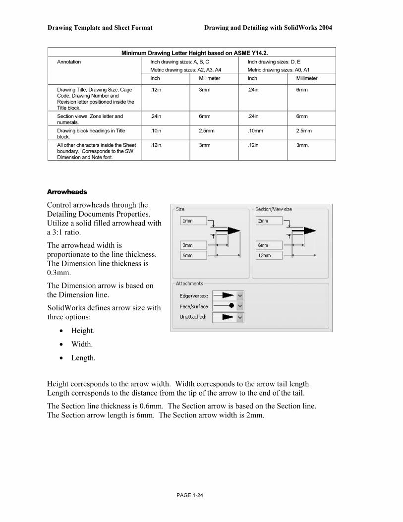
Arrowheads
Control arrowheads through the Detailing Documents Properties. Utilize a solid filled arrowhead with a 3:1 ratio.
The arrowhead width is proportionate to the line thickness. The Dimension line thickness is 0.3mm.
The Dimension arrow is based on the Dimension line.
SolidWorks defines arrow size with three options:
• Height.
• Width.
• Length.
Height corresponds to the arrow width. Width corresponds to the arrow tail length. Length corresponds to the distance from the tip of the arrow to the end of the tail.
The Section line thickness is 0.6mm. The Section arrow is based on the Section line. The Section arrow length is 6mm. The Section arrow width is 2mm.

Drawing and Detailing with SolidWorks 2004 Drawing Template and Sheet Format
PAGE 1-25
Line Widths
The ASME Y14.2M-1992 (R1998) standard recommends two line widths with a 2:1 ratio. The minimum width of a thin line is 0.3mm. The minimum width of a thick, “normal” line is 0.6mm.
Note: A single width line is acceptable on CAD drawings. Two line widths are used in this Project: Thin: 0.3mm and Normal: 0.6mm.
Apply Line Styles in the Line Font Document Properties. Line Font determines the appearance of a line in the Graphics window. SolidWorks styles utilized in this Project are as follows:
SolidWorks Line Style: Thin: (0.3mm) Normal: (0.6mm)
Solid
Dashed
Phantom
Chain
Center
Stitch
Thin/Thick Chain
Various printers/plotters provide variable Line Weight settings.
Example: Thin (0.3mm), Normal (0.6mm) and Thick (0.6mm).
Refer to the printer/plotter owner’s manual for Line weight setting.
Scale large drawing sheets with the Resolution and Scale option located in the File, Page Setup menu.
Use the Scale to fit option to resize the drawing sheet to the physical paper size.
Use Scale to resize the drawing sheet by a percentage to the physical paper size.
Drawing Template and Sheet Format Drawing and Detailing with SolidWorks 2004
PAGE 1-26
Extension Line Leader Line
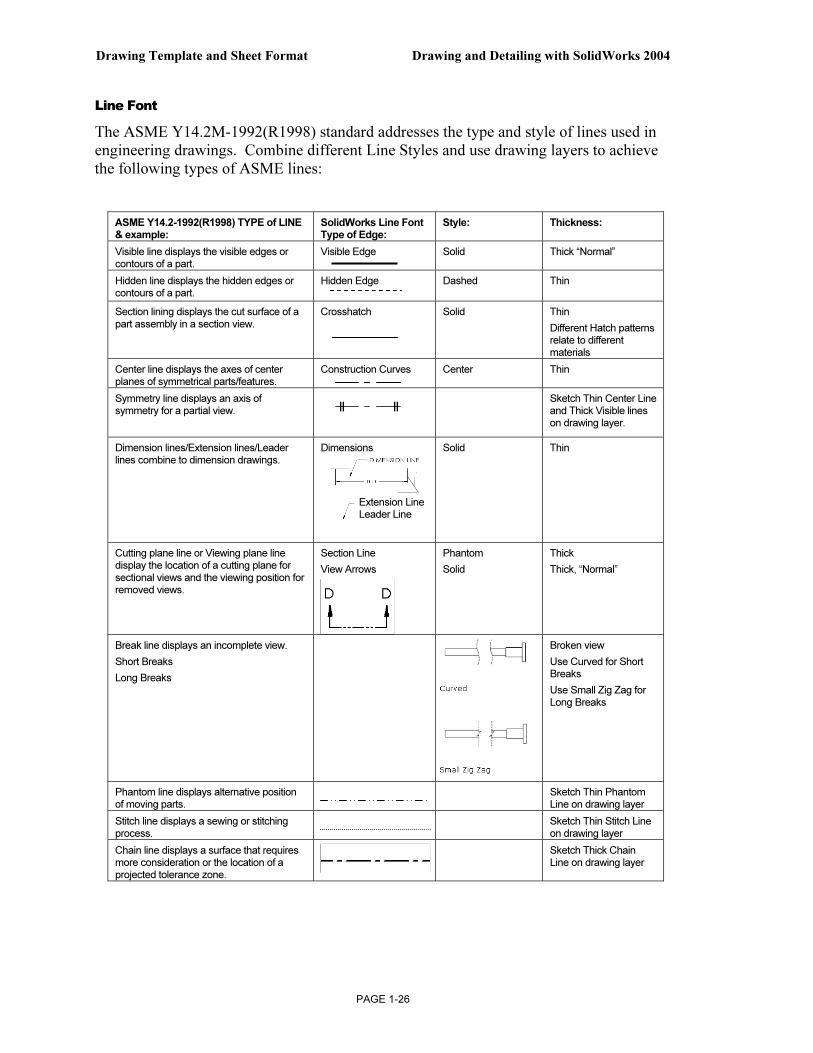
Line Font
The ASME Y14.2M-1992(R1998) standard addresses the type and style of lines used in engineering drawings. Combine different Line Styles and use drawing layers to achieve the following types of ASME lines:
ASME Y14.2-1992(R1998) TYPE of LINE & example:
SolidWorks Line Font Type of Edge:
Style: Thickness:
Visible line displays the visible edges or contours of a part.
Visible Edge Solid Thick “Normal”
Hidden line displays the hidden edges or contours of a part.
Hidden Edge Dashed Thin
Section lining displays the cut surface of a
part assembly in a section view.
Crosshatch Solid Thin
Different Hatch patterns relate to different materials
Center line displays the axes of center planes of symmetrical parts/features.
Construction Curves Center Thin
Symmetry line displays an axis of symmetry for a partial view.
Sketch Thin Center Line and Thick Visible lines on drawing layer.
Dimension lines/Extension lines/Leader lines combine to dimension drawings.
Dimensions
Solid
Thin
Cutting plane line or Viewing plane line display the location of a cutting plane for
sectional views and the viewing position for removed views.
Section Line
View Arrows
Phantom
Solid
Thick
Thick, “Normal”
Break line displays an incomplete view.
Short Breaks
Long Breaks
Broken view
Use Curved for Short Breaks
Use Small Zig Zag for
Long Breaks
Phantom line displays alternative position of moving parts.
Sketch Thin Phantom Line on drawing layer
Stitch line displays a sewing or stitching process.
Sketch Thin Stitch Line
on drawing layer
Chain line displays a surface that requires more consideration or the location of a projected tolerance zone.
Sketch Thick Chain Line on drawing layer

Drawing and Detailing with SolidWorks 2004 Drawing Template and Sheet Format
PAGE 1-27
The following line types are not pre-defined in SolidWorks:
• Symmetry line.
• Phantom line.
• Stitch line.
• Chain line.
Define these line types on a separate drawing layer.
Document Properties, Detailing
Control Detailing options through Document Properties.
The Dimensioning standard determines the display on the drawing.
Millimeter dimensioning and decimal inch dimensioning are the two key types of units specified on engineering drawings.
There are other dimension types specified for commercial commodities such as pipe sizes and lumber sizes.
Develop separate drawing templates for decimal inch units.
ASME Y14.2-1992(R1998) and the ASME Y14.2M Line Conventions and Lettering standard define text height, arrows and line styles for inch and metric values.
Review the Detailing Document Properties options function before entering their values.

Drawing Template and Sheet Format Drawing and Detailing with SolidWorks 2004
PAGE 1-28
Dimensioning Standard
The Dimensioning standard options are: ANSI, ISO, DIN, JIS, BSI, GOST and GB.
Dimensioning standard options Abbreviation Description
ANSI American National Standards Institute.
ISO International Standards Organization
DIN Deutsche Institute für Normumg (German)
JIS Japanese Industry Standard
BSI British Standards Institution
GOST Gosndarstuennye State Standard (Russian)
GB Guo Biao (Chinese)
Dual dimensions display option
The Dual dimensions display check box shows dimensions in two types of units on the drawing.
Select Dual dimensions display. Select the On top option.
The primary units display is 100mm.
The secondary units display is [3.94]in.
Fixed size weld symbols option
The Fixed size weld symbols checkbox displays the size of the weld symbol. Scale the symbols according to the dimension font size.
Display datums per 1982 option
The Display datums per 1982 checkbox displays the ANSI Y14.5M-1982 datums. Use the ASME Y14.5M-1994(R1999) datums in this text.

Drawing and Detailing with SolidWorks 2004 Drawing Template and Sheet Format
PAGE 1-29
Leading Zeroes and Trailing Zeroes option
The Leading zeroes list box contains three options:
• Standard.
• Show.
• Remove.
The Trailing zeroes list box contains three options:
• Smart.
• Show.
• Remove.
The default Smart option removes trailing zeroes based on the ASME Y14 rules for trailing zeroes for dimension values.
Alternative Section Display option
The ASME Y14.2M-1992(R1998) standard supports two display styles. The default section line displays a continuous Phantom line type (D-D).
Check the Alternate section display checkbox to allow for a gap in the section line (B-B).
Centerline Extension and Center marks option
The Centerline extension value controls the extension length beyond the section geometry.
Set the extension length to 3mm.
Center marks specify the default center mark size used with arcs and circles. Center marks are displayed with or without Center mark lines.
The center mark lines extend pass the circumference of the selected circle. Set the default Center mark size to 0.5mm. Select the Center mark size based on the drawing size and scale.
3mm 3mm

Drawing Template and Sheet Format Drawing and Detailing with SolidWorks 2004
PAGE 1-30
Auto insert on view creation option
Auto insert on view creation locates Center marks on the appropriate entities when a new view is inserted into a drawing.
By default Centerlines, Balloons and Dimensions marked for drawing options are not checked.
Extension lines option
The ASME Y14.2M-1992(R1998) and ASME Y14.5M-1994(R1999) standard defines extension line length and gap.
A visible gap exists between the extension line and the visible line.
The extension line extends 3mm past the dimension line.
Set the Gap option to 1.5mm. Set the Beyond dimension line option to 3mm. Note: The values 1.5mm and 3mm are a guide. Base the gap and extension line on the drawing size and scale.
Datum Feature option
The Next label specifies the subsequent upper case letter used for the Datum Feature Symbol.
The default value is A. Successive labels are in alphabetical order.
The Datum Display type Per Standard option displays a filled triangular symbol on the Datum Feature.
Break line option
The Break line gap specifies the size of the gap between the Broken view break lines. Set the Gap to 10mm. Set the Extension to 3mm.
Automatic Update on BOM option
The Automatic Update on BOM option updates the Bill of Material in a drawing if related model custom properties change.
Set the values in SolidWorks to meet the ASME standard.
ITEM NO. QTY. PART NO. MATERIAL
1 1 10-0408 ALUMINUM
2 1 10-0409 STEEL
3mm
1.5mm
10mm

Drawing and Detailing with SolidWorks 2004 Drawing Template and Sheet Format
PAGE 1-31
Note: Set units before entering values for Detailing options. Units for the Default Templates are determined from initial SolidWorks installation options.
Activity: Document Properties, Detailing
Set Units. 49) Click Tools, Options.
50) Click Document Properties tab.
51) Select Units from the left text box.
52) Click MMGS for the Unit system.
53) Enter 2 for Decimal places for Length units millimeters.
54) Select inches for Dual units. Enter 3 for inch Decimal places.
55) Enter 1 for Decimal places for Angular units.
Set Detailing options. 56) Click Detailing.
57) Select ANSI from the Dimensioning standard drop down list. Detailing options are available depending on the selected standard.
58) Enter 3mm for the Centerline extension.
59) Enter 0.5mm for the Center marks.
60) Modify the Witness lines (Extension line) values. Enter 1.5mm for Gap.
61) Enter 3mm for Beyond dimension line.
62) Enter 10mm for the Break line gap.

Drawing Template and Sheet Format Drawing and Detailing with SolidWorks 2004
PAGE 1-32
63) Enter 3mm for Extension for the Break line.
Note: There is no set value for the Break line gap. Increase the value to accommodate a revolved section.
64) Click the Help button located at the bottom right corner of the Detailing Properties box to view additional information on the Detailing Options.
65) Click OK.
Drawing and Detailing with SolidWorks 2004 Drawing Template and Sheet Format
PAGE 1-33
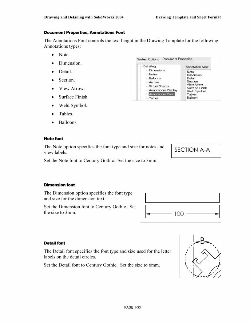
Document Properties, Annotations Font
The Annotations Font controls the text height in the Drawing Template for the following Annotations types:
• Note.
• Dimension.
• Detail.
• Section.
• View Arrow.
• Surface Finish.
• Weld Symbol.
• Tables.
• Balloons.
Note font
The Note option specifies the font type and size for notes and view labels.
Set the Note font to Century Gothic. Set the size to 3mm.
Dimension font
The Dimension option specifies the font type and size for the dimension text.
Set the Dimension font to Century Gothic. Set the size to 3mm.
Detail font
The Detail font specifies the font type and size used for the letter labels on the detail circles.
Set the Detail font to Century Gothic. Set the size to 6mm.
SECTION A-A

Drawing Template and Sheet Format Drawing and Detailing with SolidWorks 2004
PAGE 1-34
Section font
Section font specifies the font type and size used for the letter labels on the section lines.
Set the Section font to Century Gothic. Set the size to 6mm.
View font
The View Arrow font specifies the font type and size used for the letter labels on the view arrows.
Set the View Arrow font to Century Gothic. Set the size to 6mm.
Surface Finish, Weld Symbol and Balloon font
The Surface Finish, Weld Symbol and Balloon fonts specify the font type and size used for the letter labels for Surface Finish, Weld Symbols and Balloons.
Set the Surface Finish, Weld Symbol and Balloon font to Century Gothic. Set the size to 3mm.
Tables font
The Tables font varies from company to company. Tables font controls the Bill of Materials, Revision Table, Weldment Cut List and Hole Table. Set the size to 3mm.
Activity: Document Properties, Annotations font
Set the font. 66) Click the Note option button.
67) Enter 3mm for text.
68) Repeat for the Dimension font.
69) Repeat for the Surface Finish, Weld Symbols, Balloon and Table font.

Drawing and Detailing with SolidWorks 2004 Drawing Template and Sheet Format
PAGE 1-35
Set the font. 70) Click the Detail font button.
71) Enter 6mm for text.
72) Repeat for the Section font.
73) Repeat for the View Arrow font.
Note: Companies vary the size of their default font. ASME Y14.2 lists the annotation values as minimum letter heights.
Document Properties, Dimensions options
The Document Properties, Detailing, Dimensions options determine the display of dimensions.
The Dimension options determine the display and position of the text and extension lines.
Reference dimensions require parentheses. Symmetric feature dimensions in the part require a redefined dimensioning scheme in the drawing.
Uncheck the Add parentheses by default to conserve design time. Add Parenthesis to a dimension in the drawing. Right-click on the dimension text. Click Properties. Check Display with parentheses.
( )

Drawing Template and Sheet Format Drawing and Detailing with SolidWorks 2004
PAGE 1-36
Offset Distances option
The ASME Y14.5M-1994(R1999) standard sets guidelines for dimension spacing. The space between the first dimension line and the part profile is 10mm or greater.
The space between subsequent parallel dimension lines is 6mm or greater.
Spacing differs depending on drawing size and scale. Set the From last dimension option to 6mm. Set the From model option to 10mm.
Arrows option
The Arrows option controls the display of the Arrowheads. The ASME Y14.2M-1992(R1998) standard recommends a solid filled arrow head.
Break Dimension/Extension option
The ASME Y14.5M-1994(R1999) standard states do not cross dimension lines.
Break the extension line when the dimension line crosses close to an arrowhead.
Drag the extension line above the arrowhead. Sketch a new line collinear with the extension line below the arrowhead.
Set the Gap to 1.5mm.
Uncheck the Break around dimension arrows only option. Control individual breaks in the drawing for this project.
10 6
Drawing and Detailing with SolidWorks 2004 Drawing Template and Sheet Format
PAGE 1-37
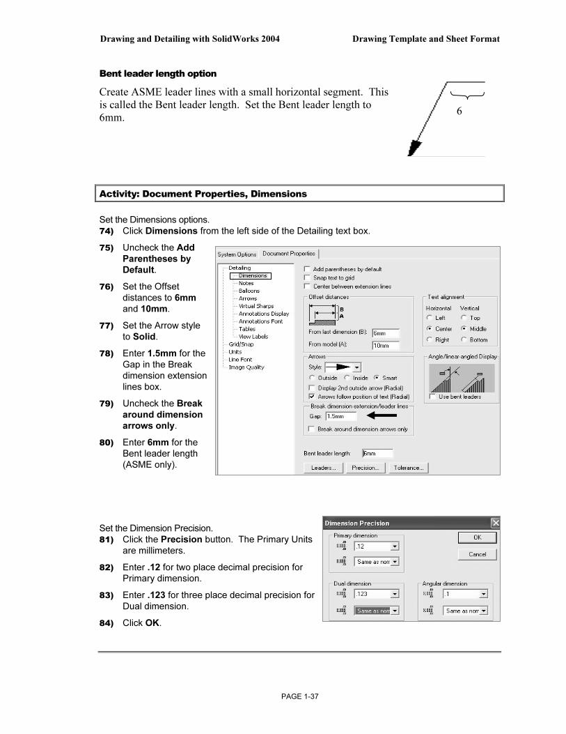
Bent leader length option
Create ASME leader lines with a small horizontal segment. This is called the Bent leader length. Set the Bent leader length to 6mm.
Activity: Document Properties, Dimensions
Set the Dimensions options. 74) Click Dimensions from the left side of the Detailing text box.
75) Uncheck the Add Parentheses by Default.
76) Set the Offset distances to 6mm and 10mm.
77) Set the Arrow style to Solid.
78) Enter 1.5mm for the Gap in the Break dimension extension lines box.
79) Uncheck the Break around dimension arrows only.
80) Enter 6mm for the Bent leader length (ASME only).
Set the Dimension Precision. 81) Click the Precision button. The Primary Units
are millimeters.
82) Enter .12 for two place decimal precision for Primary dimension.
83) Enter .123 for three place decimal precision for Dual dimension.
84) Click OK.
6

Drawing Template and Sheet Format Drawing and Detailing with SolidWorks 2004
PAGE 1-38
The Dimension Precision Value and Tolerance entries depend on drawing units and manufacturing requirements. The Tolerance button displays the Dimension Tolerance options. The Tolerance type is None by default. Control Tolerance type on individual dimensions.
Document Properties, Notes and Balloons option
Note text positioned on the drawing, outside the Title block use the same font type and height size as the Dimension font. The exceptions to the rule are:
• ASME Y14.100M-1998 Engineering Drawing Practices extended symbols.
• Use Upper case letters for all Notes unless lower case is required. Example: HCl – Hardness Critical Item requires a lower case “l”.
Modify Note Border Style to create boxes, circles, triangles and other shapes around the text.
The Default Border style is set to None. Modify the border height. Use the Size option.
2h h
h is the text
height

Drawing and Detailing with SolidWorks 2004 Drawing Template and Sheet Format
PAGE 1-39
Balloon callouts label components in an assembly and relate them to the item numbers in the Bill of Materials.
The default Balloon style is Circular.
Activity: Document Properties, Notes and Balloons
Set the Notes options. 85) Click Notes from the left side of the
Detailing text box.
86) Check Bent for Leader style.
87) Enter 6mm for the Leader length.
Set the drawing Balloon Properties. 88) Click Balloons from the
left side of the Detailing text box.
89) Uncheck Use bent leaders.
90) Enter 6mm for the Leader length.

Drawing Template and Sheet Format Drawing and Detailing with SolidWorks 2004
PAGE 1-40
Document Properties, Arrows
Set Arrows Properties according to the ASME Y14.2M-1992(R1998) standard with a 3:1 ratio: Width to Height.
The Length value is the overall length of the arrow from the tip of the arrowhead to the end of the arrow tail.
The Length is displayed when the dimension text is flipped to the inside. A Solid filled arrowhead is the preferred arrow type for dimension lines.
Activity: Document Properties, Arrows
Set the Arrows Properties. 91) Click the Arrows entry on the left side of the Detailing text box. The Detailing - Arrows
dialog box is displayed.
92) Enter 1 for the arrow Height in the Size text box.
93) Enter 3 for the arrow Width.
94) Enter 6 for the arrow Length.
95) Set the arrow style. Under the Section/View size, enter 2 for Height, 6 for Width and 12 for Length.
96) Click the solid filled arrowhead from the Edge/vertex list box.
97) Click the solid filled dot from the Face/surface list box.
Document Properties, Line Font
The Line Font determines the Style and Thickness for a particular type of edge in a drawing. Modify the Type of edge, Style and Thickness to reflect the ASME Y14.2M-1992(R1998) standard.
The ASME Y14.2M-1992(R1998) standard defines two line weights: 0.3mm and 0.6mm.
Thin Thickness is 0.3mm. Thick (Normal) Thickness is 0.6mm. Review line weights as defined in the File, Page Setup or in File, Print, System Options for your particular printer/plotter.
Arrow Length
Drawing and Detailing with SolidWorks 2004 Drawing Template and Sheet Format
PAGE 1-41
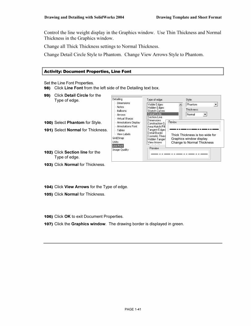
Control the line weight display in the Graphics window. Use Thin Thickness and Normal Thickness in the Graphics window.
Change all Thick Thickness settings to Normal Thickness.
Change Detail Circle Style to Phantom. Change View Arrows Style to Phantom.
Activity: Document Properties, Line Font
Set the Line Font Properties. 98) Click Line Font from the left side of the Detailing text box.
99) Click Detail Circle for the Type of edge.
100) Select Phantom for Style.
101) Select Normal for Thickness.
102) Click Section line for the Type of edge.
103) Click Normal for Thickness.
104) Click View Arrows for the Type of edge.
105) Click Normal for Thickness.
106) Click OK to exit Document Properties.
107) Click the Graphics window. The drawing border is displayed in green.
Thick Thickness is too wide for Graphics window display. Change to Normal Thickness

Drawing Template and Sheet Format Drawing and Detailing with SolidWorks 2004
PAGE 1-42
The empty Drawing Template contains no geometry. The empty Drawing Template contains the Document Properties and the Sheet Properties.
Predefined Views
In Orthographic projection the principle views are Top, Front, Right, Back, Bottom and Left. Drawings commonly display the Top, Front, Right and an Isometric view.
The Predefined option determines the Named views displayed as you drag the part into the drawing. Utilize any Named view as a Predefined view.
Insert the Front, Right, Top and Isometric views into the Drawing Template. Utilize the Predefined option to create the Front and Isometric view. Utilize the Projected option to create the Right and Top view.
The Drawing Template contains a Sheet Format. Leave space when positioning views for a 2in, (50mm) Title Block.
Save Predefined views with the Drawing Template. Save the Drawing Template in the next section, before you insert a part into the Predefined views.
Empty Drawing Template
Sheet Properties Document Properties
Save Predefined views with the
Drawing Template

Drawing and Detailing with SolidWorks 2004 Drawing Template and Sheet Format
PAGE 1-43
Activity: Predefined View
Insert the Front Predefined view. 108) Click Insert, Drawing Views, Predefined.
109) Click the lower left corner of the drawing.
110) Click Front.
111) Click Hidden Lines Visible.
112) Click OK.
Insert the Top Projected view. 113) Click Insert, Drawing Views, Projected.
114) Click a position above the Front view.
115) Check Use parent style to display Hidden Lines Visible.
116) Click OK.
Insert the Right Projected view. 117) Click Insert, Drawing Views, Projected.
118) Click a position to the Right of the Front view.
119) Check Use parent style to display Hidden Lines Visible.
120) Click OK.
Insert the Isometric Predefined view. 121) Click Insert, Drawing Views, Predefined.
122) Click the upper right corner of the drawing.
123) Click Isometric.
124) Click Hidden Lines Removed.
125) Click OK.

Drawing Template and Sheet Format Drawing and Detailing with SolidWorks 2004
PAGE 1-44
Save As
The File, SaveAs option provides the ability to save documents with various file types. The current document is a drawing named Draw1.slddrw. Save the document as a Drawing Template (.drwdot).
Select the Drawing Templates (.drwdot) option for Save as type before you browse to the MY-TEMPLATES folder. SolidWorks selects the SolidWorks\data\templates folder by default when you select Drawing Templates (.drwdot).
Test the Drawing Template located in the MY-TEMPLATES folder. Create a new drawing document.
Activity: Save As and Test Drawing Template
Save the empty Drawing Template. 126) Click File, Save As.
127) Select Drawing Templates (*.drwdot) from the Save as Type list.
128) Select Browse.
129) Select the DRAWING-W-SOLIDWORKS\ MY-TEMPLATES for the Save in file folder.
130) Enter C-SIZE-ANSI-MM-EMPTY for the File name. The file extension for the template is .drwdot.
131) Click Save.
Conserve browsing time to your favorite folder. Utilize the Save button drop down arrow, Add to Favorites option.
Add the MY-TEMPLATES folder to your Favorites folder.
Drawing and Detailing with SolidWorks 2004 Drawing Template and Sheet Format
PAGE 1-45
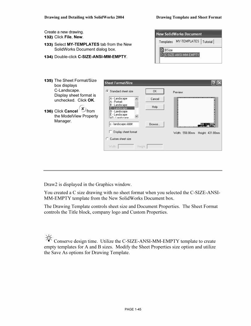
Create a new drawing. 132) Click File, New.
133) Select MY-TEMPLATES tab from the New SolidWorks Document dialog box.
134) Double-click C-SIZE-ANSI-MM-EMPTY.
135) The Sheet Format/Size box displays C-Landscape. Display sheet format is unchecked. Click OK.
136) Click Cancel from the ModelView Property Manager.
Draw2 is displayed in the Graphics window.
You created a C size drawing with no sheet format when you selected the C-SIZE-ANSI-MM-EMPTY template from the New SolidWorks Document box.
The Drawing Template controls sheet size and Document Properties. The Sheet Format controls the Title block, company logo and Custom Properties.
Conserve design time. Utilize the C-SIZE-ANSI-MM-EMPTY template to create empty templates for A and B sizes. Modify the Sheet Properties size option and utilize the Save As options for Drawing Template.
Drawing Template and Sheet Format Drawing and Detailing with SolidWorks 2004
PAGE 1-46
More Information
Additional details on Sheet Properties, System Options and Document Properties is available in Online help.
Keywords: sheet properties, paper (size), drawings (display modes, edge and display), options (annotations, balloon, detailing, dimensions, file locations, font, note and units).
Note: The keyword “options” in Online help displays all System Options and Document Property option categories.
Review
The Sheet Properties option displayed: Sheet name, scale and size. You selected a C paper size with no Sheet Format.
You reviewed the System Options Drawings and File Locations. The Drawings Display Style option controlled the display mode and tangent edges of the view.
The File Locations option created the MY-TEMPLATES folder tab in the New SolidWorks Document dialog box.
Document Properties are stored in the current document. You utilized the Detailing (Dimensions, Notes, Balloons, Arrows and Annotations Font), Line Font and Units options in the Drawing Template. There are hundreds of System Options and Document Properties.

Drawing and Detailing with SolidWorks 2004 Drawing Template and Sheet Format
PAGE 1-47
Sheet Format
Customize drawing Sheet Formats to create and match your company’s drawing standards.
A customer requests a new product. The engineer designs the product in one location, the company produces the product in a second location and the field engineer supports the customer in a third location.
The ASME Y14.24M standard describes various types of drawings.
Example: The Engineering department produces detail and assembly drawings. The drawings for machined, plastic and sheet metal parts contain specific tolerances and notes used in fabrication.
Manufacturing adds vendor item drawings with tables and notes. Field Service requires installation drawings that are provided to the customer.
Create Sheet Formats to support various standards and drawing types.
There are numerous ways to create a custom Sheet Format:
Open a “.dwg” file created with another CAD application. Save the “.dwg” file as a Sheet Format.
Right-click in the Graphics window. Select Edit Sheet Format. Create drawing borders, title block, notes and zone locations for each drawing size. Save each drawing format.
Right-click Properties in the Graphics window. Select Properties. Check Display Sheet Format option from the Sheet Format drop down list. Browse to select an existing Sheet Format.
Add an OLE supported Sheet Format such as a bitmap file of the title block and notes. Use the Insert, Object command.
ANSI
ISO
A Custom
Properties
B Custom
Properties
MACHINE
PARTS
PLASTIC
PARTS
SHEET
METAL
Empty Custom Custom
Drawing Sheet Drawing
Template Format Template

Drawing Template and Sheet Format Drawing and Detailing with SolidWorks 2004
PAGE 1-48
Utilize an existing AutoCAD drawing to create a SolidWorks Sheet Format.
Open the AutoCAD drawing as the Sheet Format. Save the C-FORMAT.slddrt
Sheet Format. Add the Sheet Format C-FORMAT.slddrt to the empty C-size Drawing Template. Create a new drawing template named C-ANSI-MM.drwdot.
Add an A-size Sheet Format, A-FORMAT.slddrt to an empty A-size Drawing Template. Create an A-ANSI-MM.drwdot Drawing Template.
FORMAT-C-ACAD.DWG C-FORMAT.SLDDRT
C-SIZE-ANSI-MM-EMPTY.DRWDOT C-FORMAT.SLDDRT
C-ANSI-MM.DRWDOT
ACAD
Sheet Format
Sheet Format Template
Template with Sheet Format
A-SIZE-ANSI-MM-EMPTY.DRWDOT + A-FORMAT.SLDDRT
A-ANSI-MM.DRWDOT
Template with Sheet Format
Sheet Format Template

Drawing and Detailing with SolidWorks 2004 Drawing Template and Sheet Format
PAGE 1-49
Insert views from the part or assembly into the SolidWorks Drawing.
Data imported from other CAD systems for a Sheet Format may require editing in SolidWorks. Delete two extraneous lines in the imported Sheet Format.
The drawing sheet contains two modes:
• Edit Sheet.
• Edit Sheet Format.
Utilize Edit Sheet to insert views and dimensions. Utilize Edit Sheet Format to modify the Title block information.
Edit in the Edit Sheet Format mode for lines and text created in the AutoCAD title block.
Add drawing notes and title block information in the Edit Sheet Format mode.
The sheet boundary and major title block headings are displayed with a THICK line style. Modify the drawing layer THICKNESS.
Top, Front, Right views of the part.
Sheet Format
Drawing Template
SolidWorks Drawing
PART/ASSEMBLY
TITLE BLOCK
LOGO
CUSTOM
PROPERTIES
ANSI
UNITS – MM
FONT/ARROWS/
LINE STYLES
LAYERS

Drawing Template and Sheet Format Drawing and Detailing with SolidWorks 2004
PAGE 1-50
Activity: Sheet Format, Import From AutoCAD
Open the AutoCAD drawing: FORMAT-C-ACAD.dwg. 137) Click File, Open.
138) Select DWG (*.dwg) from the Files of type drop down list.
139) Click Browse.
140) Select FORMAT-C-ACAD from the DRAWING-W-SOLIDWORKS\MY-SHEETFORMATS folder.
141) Click Open.
142) Click DWG(*.dwg) for Files of type.
143) Click Layers selected for sheet format.
144) Uncheck DEFPOINTS, a non-printable layer in AUTOCAD.
145) Check 0, THICKNESS, THIN and FORMAT-TEXT layers.
146) Click Next.

Drawing and Detailing with SolidWorks 2004 Drawing Template and Sheet Format
PAGE 1-51
147) Select Millimeters for Data units.
148) Select C-Landscape for Paper Size.
149) Select Browse.
150) Select the MY-TEMPLATES folder.
151) Select the C-SIZE-ANSI-MM-EMPTY for Drawing Template.
152) Click the Open button.
153) Enter 0 for the X position.
154) Enter 0 for the Y position.
155) Click Finish.
Edit the Title block. 156) Right-click in the Graphics window.
157) Click Edit Sheet Format.

Drawing Template and Sheet Format Drawing and Detailing with SolidWorks 2004
PAGE 1-52
Delete the Title block lines. 158) Click Zoom in on the Title block.
159) Click the first horizontal line below the CONTRACT NUMBER.
160) Press the Delete key.
161) Click the second horizontal line below the CONTRACT NUMBER.
162) Press the Delete key.
Align the NAME and DATE text. 163) Hold the Ctrl key down.
164) Click the NAME text.
165) Click the DATE text.
166) Right-click Align.
167) Click Uppermost.
168) Release the Ctrl key.
Display the Layer toolbar. 169) Right-click a position in the gray area, to the right of the Help menu.
170) Check Layers.
Modify Thick Layer properties. 171) Click the Layer Properties folder from the Layer toolbar.
172) Rename the AutoCAD layer THICKNESS to THICK.
173) Rename Description from THICKNESS to THICK BORDER.
174) Click the line Thickness in the THICK layer.
175) Select the second line.
176) Click OK.
The border and title block display the Thick line. The left line in the title block is on the Thin layer. Modify the line layer from the Thin layer to the Thick layer.
Drawing and Detailing with SolidWorks 2004 Drawing Template and Sheet Format
PAGE 1-53
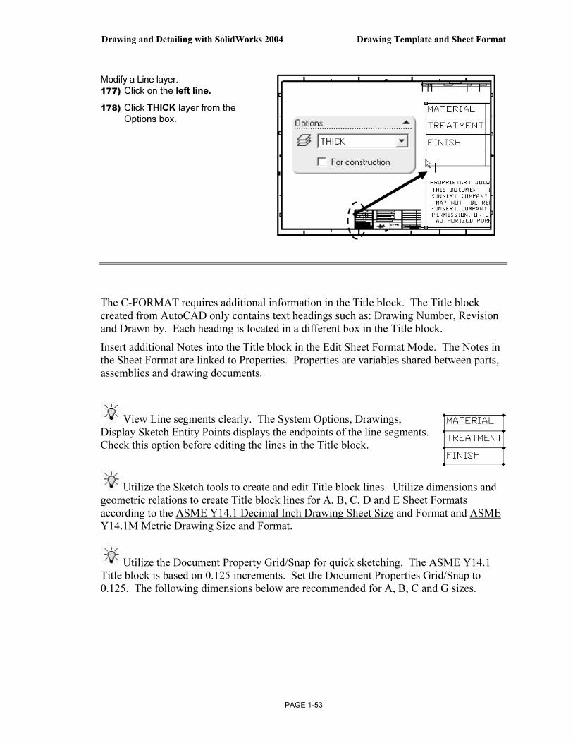
Modify a Line layer. 177) Click on the left line.
178) Click THICK layer from the Options box.
The C-FORMAT requires additional information in the Title block. The Title block created from AutoCAD only contains text headings such as: Drawing Number, Revision and Drawn by. Each heading is located in a different box in the Title block.
Insert additional Notes into the Title block in the Edit Sheet Format Mode. The Notes in the Sheet Format are linked to Properties. Properties are variables shared between parts, assemblies and drawing documents.
View Line segments clearly. The System Options, Drawings, Display Sketch Entity Points displays the endpoints of the line segments. Check this option before editing the lines in the Title block.
Utilize the Sketch tools to create and edit Title block lines. Utilize dimensions and geometric relations to create Title block lines for A, B, C, D and E Sheet Formats according to the ASME Y14.1 Decimal Inch Drawing Sheet Size and Format and ASME Y14.1M Metric Drawing Size and Format.
Utilize the Document Property Grid/Snap for quick sketching. The ASME Y14.1 Title block is based on 0.125 increments. Set the Document Properties Grid/Snap to 0.125. The following dimensions below are recommended for A, B, C and G sizes.

Drawing Template and Sheet Format Drawing and Detailing with SolidWorks 2004
PAGE 1-54
Title Block Notes and Properties
The Title block contains vital part and assembly information. Each company creates a unique version of a title block. The imported AutoCAD Sheet Format contains heading names in each area of the title block such as: TITLE, DWG NO. and SCALE.
Utilize SolidWorks System Properties and User defined Custom Properties to link Notes in the Sheet Format to the drawing, part and assembly.
System Properties
System Properties extract values from the current drawing. System Properties are determined from the SolidWorks documents. Insert System Properties as linked Notes in the Sheet Format.
System Properties begin with the prefix SW. There are two categories of Properties: System Properties and Drawing Specific System Properties.
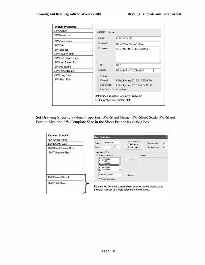
Set System Properties in the File, Properties, Summary Information dialog box as follows:
Drawing and Detailing with SolidWorks 2004 Drawing Template and Sheet Format
PAGE 1-55
System Properties:
SW-Author
SW-Keywords
SW-Comments
SW-Title
SW-Subject
SW-Created Date
SW-Last Saved Date
SW-Last Saved By
SW-File Name
SW-Folder Name
SW-Long Date
SW-Short Date
Set Drawing Specific System Properties: SW-Sheet Name, SW-Sheet Scale SW-Sheet Format Size and SW-Template Size in the Sheet Properties dialog box.
Drawing Specific:
SW-Sheet Name
SW-Sheet Scale
SW-Sheet Format Size
SW-Template Size
SW-Current Sheet
SW-Total Sheet
Determined from the Document File Name,
Folder location and System Date.
Determined from the current sheet selected in the drawing and the total number of sheets selected in the drawing.

Drawing Template and Sheet Format Drawing and Detailing with SolidWorks 2004
PAGE 1-56
User defined Properties
There are two types of User defined Properties: Custom Properties and Configuration Specific Properties.
Custom Properties link all of the configurations of a part or an assembly. Configuration Specific Properties link only a single configuration of a part or an assembly.
Assign User defined Property values to named variables in the document.
The default variables are listed in the text fileA: SolidWorks\Lang\English\Properties.txt. Create your own User defined Property named variables.
Conserve design time. Utilize System Properties and define Custom Properties and Configuration Specific Properties in your Sheet Formats.
Linked Notes
Insert Notes into the Title block. Link the Notes to SolidWorks Properties and Custom Properties.
Review your company’s Engineering Documentation Practices to determine the Notes displayed in the Title block. In the next activity, DWG NO. is linked to the SW-File Name System Property and Revision is linked to the Revision Custom Property in the part or assembly.
User Defined Properties

Drawing and Detailing with SolidWorks 2004 Drawing Template and Sheet Format
PAGE 1-57
Linked Notes begin with the four different prefixes listed below:
Prefix: Evaluated from:
$PRP: Current document.
$PRPVIEW: Model in the drawing view to which the Note is attached.
$PRPSHEET: Model in view specified in Sheet Properties.
For Sheet Format notes, the first view listed in the FeatureManager is used.
$PRPMODEL: Component to which annotation is attached.
Utilize $PRP and $PRPSHEET in the Sheet Format.
Linked Notes that reference Custom Properties in the drawing utilize the prefix: $PRP:
Enter double quotes to define the property name: Example: .
Linked Sheet Format Notes that reference Custom Properties in the part utilize the prefix: $PRPSHEET.
Linked Sheet Format Notes are displayed blank in the Edit Sheet mode.
Linked Sheet Format Notes are displayed with their property Name in the Edit Sheet Format mode. Example: .
Insert the following Linked Notes:
User-defined Custom Property Names CONTRACT NUMBER and TREATMENT are displayed in capital letters for clarity. Utilize Large and small letters for Custom Property Names.
Create a new layer for the Title block Notes. The large yellow arrow in the Name column indicates the current layer.
System Properties Linked to fields in the default Sheet Format.
Prefix: $PRP
Custom Properties of drawings linked to fields in the default Sheet Formats.
Prefix: $PRP
Custom Properties copied from the default SW Sheet Format to a Custom Sheet Format.
Prefix: $PRP
Custom Properties of parts and assemblies linked to the fields in default Sheet Formats.
Prefix:$PRPSHEET
SW-File Name (in DWG. NO. field)
CompanyName
DrawnBy DrawnDate Description
(in TITLE field):
SW-Sheet Scale CONTRACT NUMBER
CheckedBy CheckedDate Weight
SW-Current Sheet EngineeringApproval EngAppDate Material, Finish and TREATMENT
SW-Total Sheets ManufacturingApproval MfgAppDate Revision

Drawing Template and Sheet Format Drawing and Detailing with SolidWorks 2004
PAGE 1-58
Activity: Title block and SW-File Name
Insert the TB TEXT layer. 179) Click the Layer
Property Manager.
180) Click the New button.
181) Enter TB TEXT for Name.
182) Enter TITLE BLOCK TEXT for Description.
183) Click OK.
Create a Linked Note for the DWG NO. System Property.
184) Click Note from the Annotations toolbar.
185) Click a start point to the lower left of the DWG NO. text.
186) Click Link to Property from the Text Format box.
187) Select SW-File Name from the drop down list.
188) Click OK. The variable $PRP:“SW-File Name” is displayed in the Note text box.
189) Click OK.

Drawing and Detailing with SolidWorks 2004 Drawing Template and Sheet Format
PAGE 1-59
Note: Draw2 is the current file name. The Draw number varies depending on the number of drawings opened in a SolidWorks session.
The $PRP:“SW-File Name” property updates to contain the part or assembly filename.
Example: Insert the part 10-0408 into a Drawing Template.
The filename 10-0408 is linked to the SW-FileName property and is displayed in the DWG NO. box.
What action do you take to control the DWG NO. by a separate property not linked to the part filename? Answer: Create a Note linked to the Custom Property $PRP: "Number" in the Sheet Format. Enter the value 45-10032 for the Number Custom Property in the drawing document.
Size, Sheet and Scale Properties
Additional Linked Notes are required in the Title block.
Create the SIZE, SHEET and SCALE text with Linked Properties. Position the text below the headings.
The Sheet Scale value changes to reflect the sheet scale properties in the drawing.
The Sheet box combines two System Properties: SW-Current Sheet and SW-Total Sheets.
The Current Sheet value and Total Sheets value change as additional sheets are added to the drawing.
Activity: Size, Sheet and Scale Properties
Create a Linked Property to the SIZE text.
190) Click Note from the Annotations toolbar.
191) Click a start point in the upper left hand corner below the SIZE text.
192) Click Link to Property from the Text Format box.
193) Select SW-Sheet Format Size from the drop down list.
194) Click OK. The variable $PRP:“SW-Sheet Format Size” is displayed in the Note text box.
195) Click OK.
DWG NO
10-0408

Drawing Template and Sheet Format Drawing and Detailing with SolidWorks 2004
PAGE 1-60
Modify the font size and style. 196) Uncheck the Use document’s font.
197) Enter 5 for font height. Click Bold for style.
198) Click OK.
Create a Linked Property to SCALE.
199) Click Note from the Annotations toolbar.
200) Click a start point in the upper left hand corner below the SCALE text.
201) Click Link to Property .
202) Select SW-Sheet Scale from the drop down list.
203) Click OK. The variable $PRP:“SW-Sheet Scale” is displayed in the Note text box.
204) Click OK.
Delete the text. 205) Click the OF text in the lower right corner of the title block.
206) Press the Delete key.
Combine Link Properties for the SHEET text.
207) Click Note from the Annotations toolbar.
208) Click a start point in the upper left hand corner below the SHEET text.
209) Click Link to Property from the Text Format box.
210) Select SW-Current Sheet from the drop down list.
211) Click OK.
212) Enter the text OF.
213) Click Link to Property from the Text Format box.
214) Select SW-Total Sheets from the drop down list. The variable $PRP:”SW-Total Sheets” is displayed in the Note text box.
215) Click OK.

Drawing and Detailing with SolidWorks 2004 Drawing Template and Sheet Format
PAGE 1-61
Custom Property and Logo Picture
Utilize D&M ENGINEERING or your own value for CompanyName in the next step. The CompanyName Property is controlled through a Custom Property in the Sheet Format.
The Company logo is a picture file inserted as an OLE object into the drawing.
Activity: Custom Property and Logo Picture
Delete the current Company Name Note text. 216) Right-click the D&M Engineering text.
217) Click Properties.
218) Delete D&M Engineering in the Properties Note text box.
Insert the CompanyName Property.
219) Enter in the Note text box.
220) Click Link to Property .
221) Select the File Properties button from the Link to Property box.
Logo Company Name

Drawing Template and Sheet Format Drawing and Detailing with SolidWorks 2004
PAGE 1-62
222) Click the Custom tab from the
Summary Information box.
223) Select CompanyName.
224) Enter D&M ENGINEERING for
CompanyName in the Value box.
225) Click the Add button.
226) Click OK three times.
The Title block displays the
CompanyName Linked Note.
Modify the Font size.
227) Uncheck Use document’s font from the Note
PropertyManager.
228) Click the Font button. Increase or decrease the font size to fit
the Title block.
229) Click OK.
230) Click OK from the Note Property Manager.
Position the mouse pointer over the Linked Note to
display the Custom Property value.
A company logo is normally located in the title block. Create a company logo by
inserting a picture file into the Title block.
Example: the picture file 3-Gears.jpg is located in the MY-SHEETFORMATS folder.
Utilize any picture file, scanned image or bitmap.
Insert a picture.
231) Click Insert, Object from the Main toolbar.
232) Click Create From File.
233) Click Browse. Select MY-
SHEETFORMATS\3-GEARS.JPG.
234) Click Edit, Paste.
235) Size the picture to the SolidWorks title block by dragging the picture handles.
Drawing and Detailing with SolidWorks 2004 Drawing Template and Sheet Format
PAGE 1-63
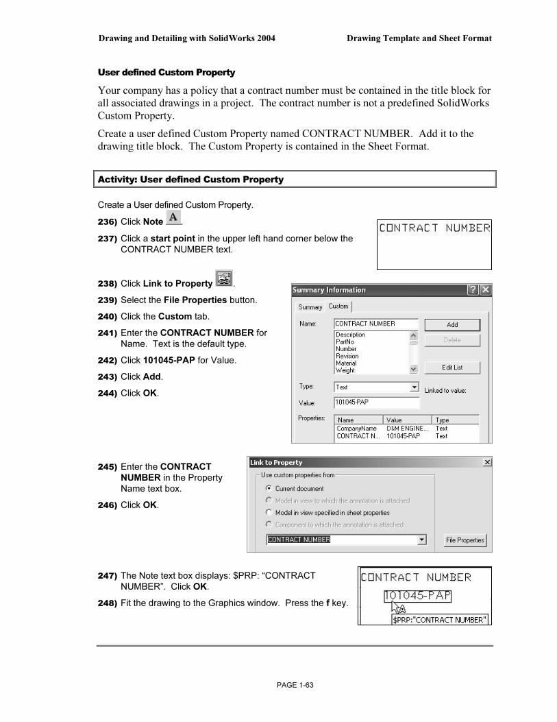
User defined Custom Property
Your company has a policy that a contract number must be contained in the title block for all associated drawings in a project. The contract number is not a predefined SolidWorks Custom Property.
Create a user defined Custom Property named CONTRACT NUMBER. Add it to the drawing title block. The Custom Property is contained in the Sheet Format.
Activity: User defined Custom Property
Create a User defined Custom Property.
236) Click Note .
237) Click a start point in the upper left hand corner below the CONTRACT NUMBER text.
238) Click Link to Property .
239) Select the File Properties button.
240) Click the Custom tab.
241) Enter the CONTRACT NUMBER for Name. Text is the default type.
242) Click 101045-PAP for Value.
243) Click Add.
244) Click OK.
245) Enter the CONTRACT NUMBER in the Property Name text box.
246) Click OK.
247) The Note text box displays: $PRP: “CONTRACT NUMBER”. Click OK.
248) Fit the drawing to the Graphics window. Press the f key.

Drawing Template and Sheet Format Drawing and Detailing with SolidWorks 2004
PAGE 1-64
Copy/Paste Custom Properties
Conserve design time. Share information from Templates and Sheet Formats. Copy DrawnBy, DrawnDate, CheckedBy, CheckedDate, EngineeringApproval, EngAppDate, ManufacturingApproval and MfgAppDate from a default SolidWorks C Sheet Format to the custom C Format.
Activity: Copy Custom Properties
Open the default SolidWorks C Drawing Template.
249) Click New.
250) Select the Templates tab.
251) Double-click Drawing.
252) Select C-landscape for the Sheet Format.
Invoke the Edit Sheet Format mode. 253) Right-click in the sheet boundary.
254) Click Edit Sheet Format.
Copy the drawing Custom Properties. 255) Window-select the text in the Name column and
the Date column. Do not select the QA text row.
256) Press Ctrl-C.
257) Press Ctrl-Tab to return to the custom C Sheet Format.
258) Click a position between the NAME and DATE column and the CHECKED and ENG APPR. row.
259) Press Ctrl-V.
260) Window-select the text in the Name column and the Date column.
261) Drag the text to center in the NAME column and DATE column.
262) Position the mouse pointer on the DrawnBy text. The Custom Property $PRP:”DrawnBy” is displayed.
The NAME and DATE Custom Properties are saved with the Sheet Format. Enter the values for NAME and DATE in the drawing.

Drawing and Detailing with SolidWorks 2004 Drawing Template and Sheet Format
PAGE 1-65
Custom Properties in Parts and Assemblies
Define Custom Properties in parts and assemblies through the ConfigurationManager, Properties option. Insert Custom Properties from a part or assembly into the drawing. Create Description, Weight, Material and Revision Custom Properties as Linked Notes in the Sheet Format. Enter values for these Custom Properties in the part or assembly.
Activity: Custom Properties in Parts and Assemblies
Insert the Description Property. 263) Click Note.
264) Click a position to the right of the TITLE.
265) Enter $PRPSHEET: “Description”.
266) Click OK.
The Note displays $PRPSHEET:{Description}. Enter the Description value in the part or assembly Custom Properties. The value is linked to the TITLE box Note.
Insert the Revision Property. 267) Click Note.
268) Click a position below the REV text.
269) Enter $PRPSHEET: “Revision”.
270) Click OK.
The Note displays $PRPSHEET:{Revision}. Enter the Revision value in the part or assembly Custom Properties.
Edit the WEIGHT text and append the text $PRPSHEET:“WEIGHT”.
Insert the Weight Property. 271) Right-click WEIGHT text.
272) Click Properties.
273) Enter $PRPSHEET:”Weight” to the right of the WEIGHT text.
274) Click OK.
Insert the Material Property. 275) Delete the ------ to the right of the MATERIAL box.
276) Click Note.
277) Enter $PRPSHEET:”Material” to the right of the MATERIAL box.
278) Click OK.

Drawing Template and Sheet Format Drawing and Detailing with SolidWorks 2004
PAGE 1-66
279) Repeat for TREATMENT. Enter $PRPSHEET:”TREATMENT” to the right of the TREATMENT box.
280) Repeat for FINISH. Enter $PRPSHEET:”Finish” to the right of the FINISH box.
Description, Revision, Weight, Material and Finish are predefined Custom Properties. Assign values in the part and assembly. The TREATMENT Custom Property is not defined. Create the TREATMENT Custom Property Name and value in the part through the ConfigurationManager, Custom Properties or a Design Table.
General Notes
General notes are annotations that describe additional information on a drawing. Conserve drawing time. Place common general notes in the Sheet Format.
The Engineering department stores general notes in a Notepad file, GENERALNOTES.TXT. General notes are usually located in a corner of a drawing.
Activity: General Notes
281) Minimize the SolidWorks window. Do not close.
Create general notes from a text file. 282) Double-click on the Notepad file, MY-SHEETFORMATS\GENERALNOTES.TXT.
283) Click Ctrl A to select the text in the Notepad file.
284) Click Ctrl C to copy the text into the windows clipboard.
285) Click the Alt tab.
286) Select the SolidWorks icon.
287) Click Note from the Annotations toolbar.
288) Click a start point in the lower left hand corner of the Title block.
289) Click inside the Note text box.
290) Paste the three lines of text. Click Ctrl V.
291) Click OK.

Drawing and Detailing with SolidWorks 2004 Drawing Template and Sheet Format
PAGE 1-67
Tables
There are four different SolidWorks tables: Revision Table, Bill of Materials, Weldment and Hole Tables. Each table contains an Anchor point. An Anchor point locates the Table position in the Sheet Format. Access to the Anchor point is through the Table entry in the FeatureManager.
The Revision Table documents the history of a drawing. Locate the Revision Table Anchor point in the upper right corner of the Sheet Format. Address other tables in future projects.
Activity: Revision Table Anchor Point
Delete the current Revision Table created in the Autocad format. 292) Zoom in on the upper right corner of the Sheet Format.
293) Window-select the Revision Table.
294) Click Delete.
Return to the drawing sheet. 295) Right-click in the Graphics window.
296) Click Edit Sheet.
297) Fit the drawing to the Graphics window. Press the f key.
Set the default layer. 298) Click None from the Layer text box.
Set the Revision Table anchor point. 299) Expand Sheet Format1 in the Drawing FeatureManager.
300) Right-click Revision Table Anchor1.

Drawing Template and Sheet Format Drawing and Detailing with SolidWorks 2004
PAGE 1-68
301) Click a position in the upper right corner of the Title block. You are in the Edit Sheet Format mode.
302) Right-click a position in the Graphics window.
303) Click Edit Sheet.
Two additional areas of the title block require editing. This action is addressed as an exercise at the end of the project.
The AutoCAD Format utilized blocks in the original Proprietary Document statement.
The paragraph was imported. Letters are missing. Each line is a separate block.
Delete the old note. Retype the note in SolidWorks.
The Tolerance block is located in the title block. The Tolerance block provides information to the manufacturer on the minimum and maximum variation for each dimension on the drawing. If a specific tolerance or note is provided on the drawing, the specific tolerance or note will override the information in the Tolerance block.
Imported from Autocad, in block format.
Recreated in SolidWorks in paragraph format.

Drawing and Detailing with SolidWorks 2004 Drawing Template and Sheet Format
PAGE 1-69
The design requirements and the manufacturing process determine the general tolerance values.
The original Tolerance block lists values for inch parts. The Sheet Format is developed for a metric part. Modify the LINEAR DIMENSIONS tolerance to +/- 0.2mm.
More Information
Additional details on Sheet Properties, Properties and Custom Properties are available in Online help. Keywords: sheet properties, properties (custom, summary information), link (notes to property) and tables (anchor).
Review
The Sheet Format contains System Properties, Custom Properties and General Notes.
SW-File Name, SW-Sheet Scale, SW-Current Sheet and SW-Total Sheets were Notes in the Sheet Format linked to System Properties.
CompanyName, CONTRACT NUMBER, DrawnBy and DrawnDate were Notes in the Sheet Format linked to the Drawing Custom Properties. DrawnBy and DrawingDate were copied from an existing default Sheet Format.
Description, Revision, Material, Weight, Finish, and TREATMENT were Notes in the Sheet Format linked to Custom Properties in the part and assembly.
You inserted a picture file as an OLE object for a company logo and General Notes from a text file. You utilized a table anchor point to position future Revision Tables in the Title block.
Create Sheet Formats for different parts types. Example: sheetmetal parts, plastic parts and high precision machined parts. Create Sheet Formats for each category of the parts that are manufactured with unique sets of Notes and Custom Properties.
Review the Engineering Drawing Practices in your company as they relate to Custom Properties and Sheet Formats. Create a table. List the following:
• Identify the required Sheet Formats.
• Identify the required SolidWorks Properties to control the design process.
• Identify the required Custom Properties to control the design process.
• Determine the required values for each Property.
• Determine the correct location to define the Property: part, assembly or drawing.

Drawing Template and Sheet Format Drawing and Detailing with SolidWorks 2004
PAGE 1-70
Save Sheet Format and Save Drawing Template
The Sheet Format (.slddrt) and Drawing Template (.drwdot) utilize two different commands to save the current drawing document (.drw). Utilize the File, Save Sheet Format option to create the Sheet Format. Sheet Formats are stored in the MY-SHEETFORMATS folder.
Utilize the File, Save As and select Drawing Template option to create the Drawing Template.
Combine the C-FORMAT Sheet Format with the empty Drawing Template. The C-FORMAT Sheet Format is contained in every Sheet of the drawing in the C-ANSI-MM Drawing Template.
Save the Sheet Format and Drawing Templates in the Edit Sheet mode. Insert Views into the drawing in Edit Sheet mode. Views cannot be displayed in the Edit Sheet Format mode.
Set the layer option to None. The current layer saves with the Drawing Template.
Create a new drawing to test the Sheet Format and the Drawing Template. The Add Sheet option inserts a second sheet into the current drawing.
Activity: Sheet Format and Drawing Template
Save the Sheet Format. 304) Click File, Save Sheet
Format.
305) Click Browse.
306) Select the MY-SHEETFORMATS for Save in folder.
307) Select the C-FORMAT.slddrt sheet format.
308) Click Save.
309) Click Yes to overwrite the existing sheet format.
310) Click OK.
The Sheet Formats1 icon is displayed in the Feature Manager.

Drawing and Detailing with SolidWorks 2004 Drawing Template and Sheet Format
PAGE 1-71
Save the Drawing Template. 311) Click File, Save As.
312) Select Drawing Template (*drwdot) for Save as Type.
313) Select MY-TEMPLATES for Save in folder.
314) Enter C-ANSI-MM for File name.
315) Click Save.
Close all documents. 316) Click Windows, Close All.
317) Click No to the questions: “Save DRAW1 and Save DRAW2.”
Verify the template. 318) Click New.
319) Click the MY-TEMPLATES tab.
320) Click the C-ANSI-MM template. The C-ANSI-MM Drawing Template is displayed with the Sheet Format.
321) Click OK.
Add Sheet2 322) Right-click the Sheet1 tab.
323) Click Add Sheet. The C-Format is select in the Sheet Properties dialog box.
324) Click OK.
Close all files. 325) Click Windows.
326) Click Close All.

Drawing Template and Sheet Format Drawing and Detailing with SolidWorks 2004
PAGE 1-72
A - size Drawing Template
Create an A size Drawing Template and an A size Sheet Format. Text size for an A-size drawing is the same as a C-size drawing.
Utilize the empty C-size Drawing Template to copy the Document Properties.
Create an A-ANSI-MM Drawing Template. Add an A-size Sheet Format.
SolidWorks copies the Document Properties in the C-size Drawing Template to the A-size Drawing Template.
The MY-SHEETFORMATS folder contains a predefined Sheet Format named, A-FORMAT. The A-FORMAT contains geometry, text and dimensions. The current layer is set to None.
The Drawing Template controls the units.
Activity: A-size Drawing Template
Create a new A-size drawing template. 327) Click New.
328) Select C-SIZE-ANSI-MM-EMPTY.
329) Uncheck Display Sheet Format.
330) Select A-Landscape for Standard sheet size.
331) Click OK.
Fit the template to the Graphics window. 332) Press the f key.
Save the A-size Drawing Template. 333) Click File, Save As.
334) Select Drawing Templates for Save as type.
335) Browse to the MY-TEMPLATES file folder.
336) Enter A-SIZE-ANSI-MM-EMPTY for File name.
337) Click the Save button.

Drawing and Detailing with SolidWorks 2004 Drawing Template and Sheet Format
PAGE 1-73
Load the Custom A-size sheet format. 338) Right-click in the Graphics
window.
339) Click Properties.
340) Click Standard sheet format for the Sheet Format.
341) Click Browse.
342) Select A-FORMAT.slddrt from the MY-SHEETFORMAT file folder.
343) Click OK.
Save the new Drawing Template. 344) Click File, SaveAs.
345) Select Drawing Templates(*.drwdot) for Save as type.
346) Select the MY-TEMPLATES file folder.
347) Enter A-ANSI-MM.
Close all documents. 348) Click Windows, Close All.
Verify the Template. 349) Click New.
350) Click the MY-TEMPLATES tab.
351) Click the A-ANSI-MM template.
352) Click OK.

Drawing Template and Sheet Format Drawing and Detailing with SolidWorks 2004
PAGE 1-74
Close all documents. 353) Click Windows, Close All.
Project Summary
In this project, you created a custom C-size and A-size Drawing Template and Sheet Format. The Drawing Template and Sheet Format contained global drawing and detailing standards.
You obtained and applied drawing properties that reflect the ASME Y14 Engineering Drawing and Related Drawing Practices.
You performed the task of importing an AutoCAD drawing to create and modify a custom Sheet Format.
The Sheet Format utilized System Properties and User defined Custom Properties through Linked Notes.
The A-ANSI-MM and C-ANSI-MM Drawing Templates and A-FORMAT and C-FORMAT Sheet Formats are use in the next Project.
Review additional topics in the project exercise. Example: Create Drawing Templates for inch Document Properties. Import a Pro\ENGINEER Sheet Format into SolidWorks.
Project Terminology
ANSI: American National Standards Institute.
ASME: American Society of Mechanical Engineers. ASME is the publisher of the Y14 Engineering Drawing and Related Documentation Practices. ASME Y14.5M-1994 is a revision of ANSI Y14.5-1982.
CommandManager: Display of toolbars based on the selection in the Control Area.
Drawing Template: A document that is the foundation of a new drawing. The Drawing Template contains document properties and user-defined parameters such as sheet format. The extension for the Drawing Template filename is .DRWDOT.

Drawing and Detailing with SolidWorks 2004 Drawing Template and Sheet Format
PAGE 1-75
Drawing: A 2D representation of a 3D part or assembly. The extension for a SolidWorks drawing filename is .SLDDRW.
Feature Manager: An outline view of the active part, assembly or drawing displayed on the left side of the SolidWorks window.
Hidden Lines Removed (HLR): A view mode. All edges of the model that are not visible from the current view angle are removed from the display.
Hidden Lines Visible (HLV): A view mode. All edges of the model that are not visible from the current view angle are shown gray or dashed.
Import: The ability to open files from other software applications into a SolidWorks document. The A-size sheet format was created as an AutoCAD file and imported into SolidWorks.
Layers: Simplifies a drawing by combining dimensions, annotations, geometry and components. Properties such as: display, line style and thickness are assigned to a named layer.
Menus: Menus provide access to the commands that the SolidWorks software offers.
Mouse Buttons: The left and right mouse buttons have distinct meanings in SolidWorks.
OLE (Object Linking and Embedding): A Windows file format. A company logo or EXCEL spreadsheet placed inside a SolidWorks document are examples of OLE files.
Part: A 3D object made up of features. A part inserted into an assembly is called a component. Insert part views, feature dimensions and annotations into 2D drawing. The extension for a SolidWorks part filename is .SLDPRT.
Plane: To create a sketch, choose a plane. Planes are flat and infinite. Planes are represented on the screen with visible edges. The default reference plane for this project is Front.
Properties: Variables shared between documents through linked notes.
Sheet Format: A document that contains the following: page size and orientation, standard text, borders, logos and title block information. Customize the sheet format to save time. The extension for the Sheet Format filename is .SLDDRT.
Sheet: A page in a drawing document.
System Feedback: Feedback is provided by a symbol attached to the cursor arrow indicating your selection. As the cursor floats across the model, feedback is provided in the form of symbols riding next to the cursor.
Toolbars: The toolbar menus provide shortcuts enabling you to access the most frequently used commands.

Drawing Template and Sheet Format Drawing and Detailing with SolidWorks 2004
PAGE 1-76
Questions
1. Name the drawing options defined in the Drawing Template.
2. Name five drawing items that are contained in the Sheet Format.
3. Identify the paper dimensions required for an A-size horizontal drawing.
4. Identify the paper dimensions required for an A4 horizontal drawing.
5. Name the Size option you select in order to define a custom paper width and height.
6. Identify the primary type of projection utilized in a drawing in the United States.
7. Describe the steps to display and modify the properties in a drawing sheet.
8. Identify the location of the stored System Options.
9. Name the display modes for drawing views using SolidWorks 2004.
10. True or False. SolidWorks Line Font Types define all ASME Y14.2 type and
style of lines.
11. Identify all Dimensioning standards options supported by SolidWorks.
12. Identify 10 drawing items that are contained in a title block.
13. SolidWorks Properties are saved with the __________________ Format.
14. The Drawing Template ends with the file extension _____________.
15. A Sheet Format ends with the file extension ______________.
16. An AutoCAD drawing ends with the file extension __________.
17. Describe the procedure to insert a Picture file into the Sheet Format.
18. True or False. Custom Properties are defined only in the Drawing Template.

Drawing and Detailing with SolidWorks 2004 Drawing Template and Sheet Format
PAGE 1-77
Exercises
Notes for Exercise 1.1 through Exercise 1.3:
Create Drawing Templates for both inch and Metric units. ASME Y14.5M has different rules for English and Metric unit decimal display.
English decimal display: If a dimension value is less than 1 inch, no leading zero is displayed before the decimal point. See Table 1 for details.
Metric decimal display: If a dimension value is less than 1mm, a leading zero is displayed before the decimal point. See Table 1 for details.
Specify General Tolerances in the Title Block. Specific tolerances are applied to an individual dimension.
Select ANSI for the SolidWorks Dimensioning Standard. Select inch or metric for Drawing units.
Table 1
Tolerance Display for INCH and METRIC DIMENSIONS (ASME Y14.5M)
Display Inch Metric
Dimensions less than 1 .5 0.5
Unilateral Tolerance
Bilateral Tolerance
Limit Tolerance

Drawing Template and Sheet Format Drawing and Detailing with SolidWorks 2004
PAGE 1-78
Exercise 1.1:
a) Create an A-size ANSI Drawing Template using inch units. Use an A-FORMAT Sheet Format.
b) Create a C-size ANSI Drawing Template using inch units. Use a C-FORMAT Sheet Format.
The minimum ASME Y14.2M letter height for Title Block is displayed in Table 2.
c) Create three new layers named:
• DETAILS.
• HIDE DIMS.
• CNST DIMS (Construction Dimensions).
Create new layers to display the CHAIN, PHANTOM and STITCH lines.
TABLE 2
Minimum Letter Height for TITLE BLOCK
(ASME Y14.2M)
Title Block Text Letter Height (inches) for A, B,
C Drawing Size
Drawing Title, Drawing Size, Cage Code, Drawing Number, Revision Letter
.12
Section and view letters .24
Drawing block letters .10
All other characters .10

Drawing and Detailing with SolidWorks 2004 Drawing Template and Sheet Format
PAGE 1-79
Exercise 1.2:
Create an A4(horizontal) ISO Drawing Template. Use Document Properties to set the ISO dimension standard and millimeter units.
Exercise 1.3:
Modify the SolidWorks Drawing Template A4-ISO. Edit Sheet Format to include a new Sheet Metal & Weldment Tolerances box on the left hand side of the Sheet Format, Figure EX1.3.
Display sketched end points to create new lines for the Tolerance box. Click Tools, Options, System Options, Sketch. Check Display entity points. The endpoints are displayed for Sketch lines.
Figure EX1.3
SHEET METAL & WELDMENT TOLERANCES Box
Courtesy of Ismeca, USA Inc. Vista, CA.

Drawing Template and Sheet Format Drawing and Detailing with SolidWorks 2004
PAGE 1-80
Exercise 1.4:
You are not required to have Pro/E to perform this exercise. Your company uses SolidWorks and Pro/ENGINEER to manufacture Sheet Metal parts, Figure EX1.4. Import the empty A-size drawing format, FORMAT-A-PRO-E.DWG located in the DRAWING-W-SOLIDWORKS file folder. This document was exported from Pro/E as a DWG file. Save the PRO/E drawing format as a SolidWorks Sheet Format.
Figure EX1.4
SHEET METAL STRONG TIE REINFORCING BRACKET,
Courtesy of Simpson Strong Tie Corporation, CA, USA.

Drawing and Detailing with SolidWorks 2004 Drawing Template and Sheet Format
PAGE 1-81
Exercise 1.5:
You are required to have AutoCAD to perform this exercise. Your company uses SolidWorks and AutoCAD. Open an A-size drawing template from AutoCAD. Review the Dimension Variables (DIMVARS) in AutoCAD. Record the DIMSTATUS for the following variables:
AutoCAD: Function:
DIMTXSTY Dimensioning Text Style
DIMASZ Arrow size
DIMCEN Center Mark size
DIMDEC Decimal Places
DIMTDEC Tolerance Decimal Places
DIMTXT Text Height
DIMDLI Space between dimension lines for Baseline dimensioning
Identify the corresponding values in SolidWorks Document Properties to contain the AutoCAD dimension variables. Utilize Help, Moving from AutoCAD in SolidWorks. Select CommandMap, Draw Toolbar and Dimension Toolbar.
Define Favorite dimension style settings for a particular dimension. Apply Favorite dimension styles to other dimensions on the drawing, part and assembly documents.
Note: Early AutoCAD drawing formats contain fonts not supported in a Windows environment. These fonts imported into SolidWorks will be misaligned in the Sheet Format. Modify older AutoCAD formats to a True Type Font in SolidWorks.
For additional information on the transition between 2D AutoCAD and 3D SolidWorks, select the Draw Toolbar option in Online help, Moving from AutoCAD.

Drawing Template and Sheet Format Drawing and Detailing with SolidWorks 2004
PAGE 1-82
Notes:


![Toward [hyper] drawing through ambiguity · PDF fileDrawing within three figurations: Empson’s seven types of ambiguity in literary prose (first published in 1930), the logical fallacies](https://static.fdocuments.in/doc/165x107/5a9e53607f8b9aee4a8cfe3b/toward-hyper-drawing-through-ambiguity-within-three-figurations-empsons-seven.jpg)