Power-Bolt+ (PB+) Heavy Duty Sleeve Anchor General ...
10
Mini Dropin Power-Bolt+ (PB+) Heavy Duty Sleeve Anchor PRODUCT DESCRIPTION The Power-Bolt+ (PB+) anchor is a torque controlled, heavy duty sleeve style anchor which is designed for consistent performance in cracked and uncracked concrete. Suitable base materials include normal-weight concrete and sand-lightweight concrete. The anchor is manufactured with a zinc plated carbon steel bolt, sleeve, cone and expansion clip. The PB+ has a low profile finished hex head. GENERAL APPLICATIONS AND USES • Structural connections, i.e., beam and column anchorage • Safety-related attachments and tension zone applications • Interior applications / low level corrosion environment • Heavy duty applications FEATURES AND BENEFITS + Consistent performance in high and low strength concrete + Nominal drill bit size is the same as the anchor diameter + Anchor can be installed through standard fixture holes + Length ID code and identifying marking stamped on head of each anchor + Anchor design allows for follow-up expansion after setting under tensile loading + High shear load capacity APPROVALS AND LISTINGS International Code Council, Evaluation Service (ICC-ES), ESR-3260 for cracked and uncracked concrete Code compliant with International Building Code (IBC) and International Residential Code (IRC) Tested in accordance with ACI 355.2 and ICC-ES AC193 (including ASTM E 488) for use in structural concrete under the design provisions of ACI 318 (Strength Design method using Appendix D) Evaluated and qualified by an accredited independent testing laboratory for recognition in cracked and uncracked concrete including seismic and wind loading (Category 1 anchors) GUIDE SPECIFICATIONS CSI Divisions: 03 16 00 - Concrete Anchoring and 05 05 19 - Post Installed Concrete Anchors Expansion anchors shall be Power-Bolt+ (PB+) as supplied by Powers Fasteners, Inc., Brewster, NY. Anchors shall be installed in accordance with published instructions and the Authority Having Jurisdiction. MATERIAL SPECIFICATIONS Anchor component Specification Bolt Medium carbon steel (Grade 8 equivalent) Washer Conforms to ASTM F844 Cone AISI C1035-C1040 Expansion Clip AISI C1045-C1050 Metal Sleeve Medium carbon steel tubing (seamless) Compression Ring & Retainer Nut Engineered plastic Plating Zinc plating according to ASTM B 633, SC1 Type III (Fe/Zn 5). Minimum plating requirements for Mild Service Condition. SECTION CONTENTS Page No. General Information .................... 1 Material Specifications ............... 1 Installation Instructions .............. 2 ASD Installation Specifications ... 3 Reference Performance Data ...... 4 ASD Performance Data................ 4 ASD Design Criteria...................... 5 Strength Design Information ...... 6 SD Performance Data ................... 9 Ordering Information ................ 10 Power-Bolt+ (PB+) Assembly HEAD STYLES Finished Hex Head ANCHOR MATERIALS Zinc plated carbon steel bolt, washer, cone, sleeve, and expansion clip; assembled with a plastic compression ring and retainer nut ANCHOR SIZE RANGE (TYP.) 1/2” diameter through 5/8” diameter SUITABLE BASE MATERIALS Normal-weight concrete Sand-lightweight concrete This Product Available In Powers Design Assist Real Time Anchor Design Software www.powersdesignassist.com ® S E I S M I C R E G I O N Q U A L I F I C A T I O N Power-Bolt+ (PB+) Powers USA: (800) 524-3244 or (914) 235-6300 Canada: (905) 673-7295 or (514) 631-4216 www.powers.com 1 PRODUCT INFORMATION d
Transcript of Power-Bolt+ (PB+) Heavy Duty Sleeve Anchor General ...

Mini Dropin
Power-Bolt+ (PB+) Heavy Duty Sleeve Anchor
PRODuCT DESCRIPTION
The Power-Bolt+ (PB+) anchor is a torque controlled, heavy duty sleeve style anchor which is designed for consistent performance in cracked and uncracked concrete. Suitable base materials include normal-weight concrete and sand-lightweight concrete. The anchor is manufactured with a zinc plated carbon steel bolt, sleeve, cone and expansion clip. The PB+ has a low profi le fi nished hex head.
GENERAL APPLICATIONS AND uSES
• Structural connections, i.e., beam and column anchorage• Safety-related attachments and tension zone applications• Interior applications / low level corrosion environment• Heavy duty applications
FEATuRES AND BENEFITS
+ Consistent performance in high and low strength concrete+ Nominal drill bit size is the same as the anchor diameter+ Anchor can be installed through standard fi xture holes+ Length ID code and identifying marking stamped on head of each anchor+ Anchor design allows for follow-up expansion after setting under tensile loading+ High shear load capacity
APPROVALS AND LISTINGS
International Code Council, Evaluation Service (ICC-ES), ESR-3260 for cracked and uncracked concrete Code compliant with International Building Code (IBC) and International Residential Code (IRC)
Tested in accordance with ACI 355.2 and ICC-ES AC193 (including ASTM E 488) for use in structural concrete under the design provisions of ACI 318 (Strength Design method using Appendix D)
Evaluated and qualified by an accredited independent testing laboratory for recognition in cracked and uncracked concrete including seismic and wind loading (Category 1 anchors)
GuIDE SPECIFICATIONS
CSI Divisions: 03 16 00 - Concrete Anchoring and 05 05 19 - Post Installed Concrete AnchorsExpansion anchors shall be Power-Bolt+ (PB+) as supplied by Powers Fasteners, Inc., Brewster, NY. Anchors shall be installed in accordance with published instructions and the Authority Having Jurisdiction.
MATERIAL SPECIFICATIONS
Anchor component Specifi cation
Bolt Medium carbon steel (Grade 8 equivalent)
Washer Conforms to ASTM F844
Cone AISI C1035-C1040
Expansion Clip AISI C1045-C1050
Metal Sleeve Medium carbon steel tubing (seamless)
Compression Ring & Retainer Nut Engineered plastic
Plating Zinc plating according to ASTM B 633, SC1 Type III (Fe/Zn 5). Minimum plating requirements for Mild Service Condition.
SECTION CONTENTS Page No.
General Information .................... 1
Material Specifications ............... 1
Installation Instructions .............. 2
ASD Installation Specifications ... 3
Reference Performance Data ...... 4
ASD Performance Data ................ 4
ASD Design Criteria ......................5
Strength Design Information ...... 6
SD Performance Data ...................9
Ordering Information ................ 10
Power-Bolt+ (PB+) Assembly
HEAD STYLES
Finished Hex Head
ANCHOR MATERIALS
Zinc plated carbon steel bolt, washer, cone, sleeve, and expansion clip; assembled with a plastic compression ring and retainer nut
ANCHOR SIZE RANGE (TYP.)
1/2” diameter through 5/8” diameter
SUITABLE BASE MATERIALS
Normal-weight concreteSand-lightweight concrete
This Product Available In
Powers Design AssistReal Time Anchor Design Software
www.powersdesignassist.com
®
TE
NSION ZONE
CR
ACKED CONCRE
TESE
ISMIC REGION
QUALIFICATIO
N
Power-Bolt+ (PB+)
Powers USA: (800) 524-3244 or (914) 235-6300 Canada: (905) 673-7295 or (514) 631-4216 www.powers.com 1
PRODUCT INFORMATION
d
PRODUCT INFORMATIONPower-Bolt+ (PB+)
www.powers.com Canada: (905) 673-7295 or (514) 631-4216 Powers USA: (800) 524-3244 or (914) 235-6300 2
d
1. Using the proper drill bit size, drill a hole into the base material to the required depth. The tolerances of the drill bit used should meet the requirements of ANSI Standard B212.15.
2. Remove dust and debris from the hole using a hand pump, compressed air or a vacuum.
3. Drive anchor through the fixture into the hole. Be sure the anchor is driven to the minimum required embedment depth, hnom .
4. Tighten the anchor with a torque wrench by applying the required installation torque, Tinst .
INSTALLATION INSTRuCTIONS
Installation Instructions for Power-Bolt+ (PB+) Anchor
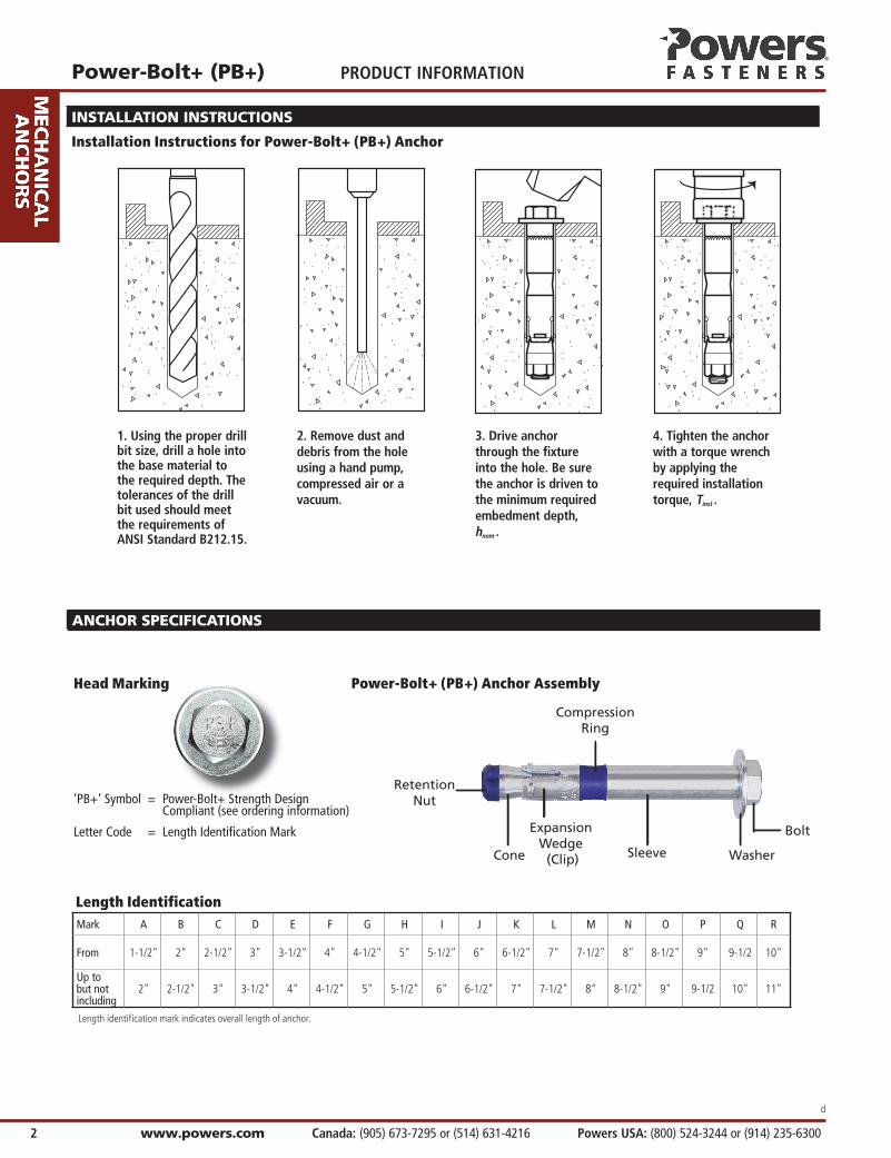
Length IdentificationMark A B C D E F G H I J K L M N O P Q R
From 1-1/2" 2" 2-1/2" 3" 3-1/2" 4" 4-1/2" 5" 5-1/2" 6" 6-1/2" 7" 7-1/2" 8" 8-1/2" 9" 9-1/2 10"
Up to but not including
2" 2-1/2" 3" 3-1/2" 4" 4-1/2" 5" 5-1/2" 6" 6-1/2" 7" 7-1/2" 8" 8-1/2" 9" 9-1/2 10" 11"
Length identification mark indicates overall length of anchor.
Head Marking
‘PB+’ Symbol = Power-Bolt+ Strength Design Compliant (see ordering information)
Letter Code = Length Identifi cation Mark
Sleeve Washer
Bolt
Cone
Expansion Wedge (Clip)
Retention Nut
Compression Ring
Power-Bolt+ (PB+) Anchor Assembly
ANCHOR SPECIFICATIONS
Power-Bolt+ (PB+)
Powers USA: (800) 524-3244 or (914) 235-6300 Canada: (905) 673-7295 or (514) 631-4216 www.powers.com 3
PRODUCT INFORMATION
d
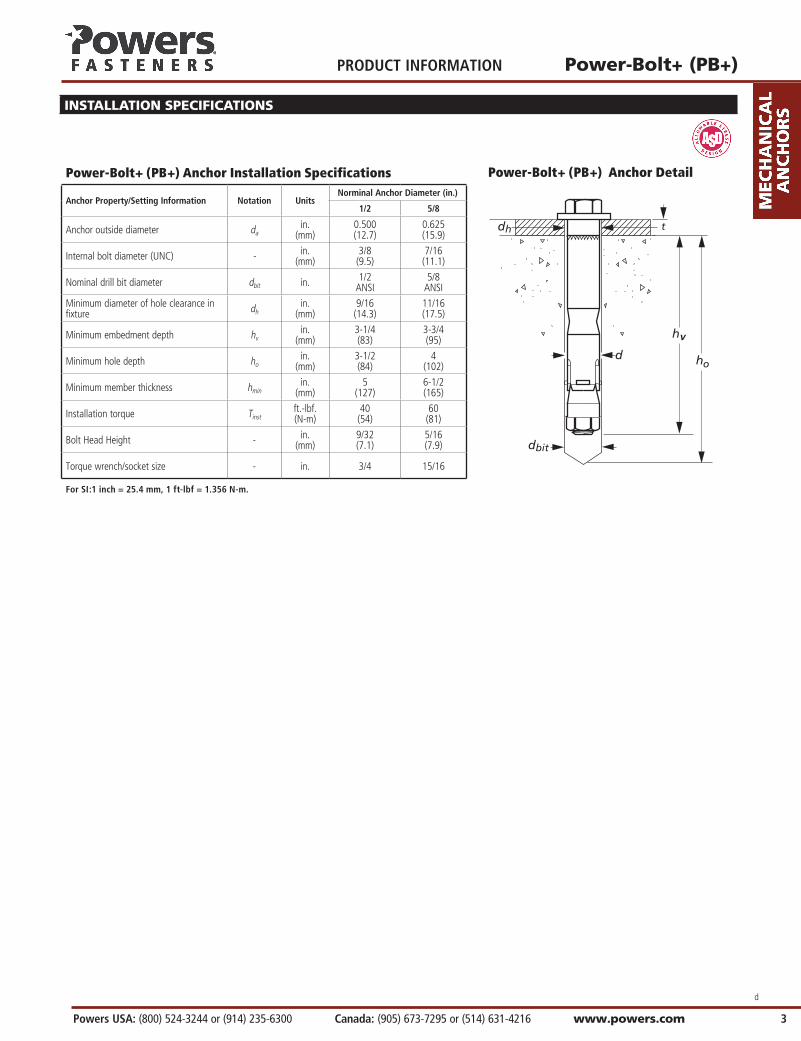
Power-Bolt+ (PB+) Anchor Installation Specifications
Anchor Property/Setting Information Notation UnitsNorminal Anchor Diameter (in.)
1/2 5/8
Anchor outside diameter da in.
(mm)0.500(12.7)
0.625(15.9)
Internal bolt diameter (UNC) - in.(mm)
3/8(9.5)
7/16(11.1)
Nominal drill bit diameter dbit in. 1/2 ANSI
5/8ANSI
Minimum diameter of hole clearance in fixture dh
in.(mm)
9/16(14.3)
11/16(17.5)
Minimum embedment depth hvin.
(mm)3-1/4(83)
3-3/4(95)
Minimum hole depth hoin.
(mm)3-1/2(84)
4(102)
Minimum member thickness hminin.
(mm)5
(127)6-1/2(165)
Installation torque Tinstft.-lbf.(N-m)
40(54)
60(81)
Bolt Head Height - in.(mm)
9/32(7.1)
5/16(7.9)
Torque wrench/socket size - in. 3/4 15/16
For SI:1 inch = 25.4 mm, 1 ft-lbf = 1.356 N-m.
Power-Bolt+ (PB+) Anchor Detail
INSTALLATION SPECIFICATIONS

PRODUCT INFORMATIONPower-Bolt+ (PB+)
www.powers.com Canada: (905) 673-7295 or (514) 631-4216 Powers USA: (800) 524-3244 or (914) 235-6300 4
d
REFERENCE PERFORMANCE DATA
ultimate Load Capacities for Power-Bolt+ (PB+) in Normal-Weight Concrete 1
Nominal Anchor
Diameter d in.
Minimum Embedment
Depth in.
Minimum Concrete Compressive Strength - f’c (psi)
2,500 3,000 4,000 6,000 8,000
Tension (lbs.)
Shear (lbs.)
Tension (lbs.)
Shear (lbs.)
Tension (lbs.)
Shear (lbs.)
Tension (lbs.)
Shear (lbs.)
Tension (lbs.)
Shear (lbs.)
1/2 2-1/2 3,880 7,420 4,250 8,030 4,905 8,030 5,150 8,030 5,518 8,030
1/2 3 5,190 8,030 5,685 8,030 6,560 8,030 7,985 8,030 9,065 8,030
1/2 3-1/4 7,120 8,030 7,660 8,030 8,645 8,030 9,400 8,030 10,835 8,030
5/8 2-3/4 4,745 9,975 5,195 10,930 6,000 12,620 6,845 13,155 7,200 13,155
5/8 3-1/2 6,995 9,975 7,660 10,930 8,845 12,620 11,325 13,155 12,900 13,155
5/8 3-3/4 8,710 12,015 9,545 14,320 11,020 16,535 12,820 18,250 14,800 18,250
1. The tabulated load values are applicable to single anchors installed in uncracked concrete with no edge or spacing considerations.
ALLOWABLE STRESS DESIGN (ASD) PERFORMANCE DATA
Allowable Load Capacities for Power-Bolt+ (PB+) in Normal-Weight Concrete 1,2,3
Nominal Anchor
Diameter d in.
Minimum Embedment
Depth in.
Minimum Concrete Compressive Strength - f’c (psi)
2,500 3,000 4,000 6,000 8,000
Tension (lbs.)
Shear (lbs.)
Tension (lbs.)
Shear (lbs.)
Tension (lbs.)
Shear (lbs.)
Tension (lbs.)
Shear (lbs.)
Tension (lbs.)
Shear (lbs.)
1/2 2-1/2 970 1,855 1,065 2,010 1,225 2,010 1,290 2,010 1,380 2,010
1/2 3 1,300 2,010 1,420 2,010 1,640 2,010 1,995 2,010 2,265 2,010
1/2 3-1/4 1,780 2,010 1,915 2,010 2,160 2,010 2,350 2,010 2,710 2,010
5/8 2-3/4 1,185 2,495 1,300 2,735 1,500 3,155 1,710 3,290 1,800 3,290
5/8 3-1/2 1,750 2,495 1,915 2,735 2,210 3,155 2,830 3,290 3,225 3,290
5/8 3-3/4 2,180 3,005 2,385 3,580 2,755 4,135 3,205 4,565 3,700 4,5651. Allowable load capacities listed are calculated using an applied safety factor of 4.0. Consideration of safety factors of 10 or higher may be necessary depending on the applications, such as life safety or overhead. 2. Tabulated load values are for anchors installed in concrete. Concrete compressive strength must be at the specified minimum at the time of installation.3. Allowable load capacities are multiplied by reduction factors when anchor spacing or edge distances are less than critical distances.

Power-Bolt+ (PB+)
Powers USA: (800) 524-3244 or (914) 235-6300 Canada: (905) 673-7295 or (514) 631-4216 www.powers.com 5
PRODUCT INFORMATION
d
Spacing Reduction Factors -Tension (FNS) Edge Distance Reduction Factors- Tension (FNC)Diameter d (in) 1/2 5/8 Diameter d (in) 1/2 5/8
Critical Spacing scr (in) 7-7/8 9 Critical Distance ccr (in) 8 6
Minimum Spacing smin (in) 4-1/2 6 Minimum Edge Distance cmin (in) 3-1/4 4-1/2
Min. Slab Thickness hmin (in) 5 6-1/2 Min. Slab Thickness hmin (in) 5 6-1/2
Minimum Embedment hv (in) 2-5/8 3 Minimum Embedment hv (in) 2-5/8 3
Spac
ing
Dist
ance
(inc
hes)
4 - -
Edge
Dist
ance
(inc
hes)
3 - -
4-1/2 0.83 - 3-1/4 0.41 -
5 0.85 - 3-1/2 0.44 -
5-1/2 0.88 - 4 0.50 -
6 0.91 0.85 4-1/2 0.56 0.75
6-1/2 0.93 0.87 5 0.63 0.83
7 0.96 0.90 5-1/2 0.69 0.92
7-1/2 0.98 0.92 6 0.75 1.00
8 1.00 0.95 6-1/2 0.81 1.00
8-1/2 1.00 0.97 7 0.88 1.00
9 1.00 1.00 7-1/2 0.94 1.00
8 1.00 1.00
Spacing Reduction Factors -Shear (FVS) Edge Distance Reduction Factors -Shear (FVC)Diameter d (in) 1/2 5/8 Diameter d (in) 1/2 5/8
Critical Spacing scr (in) 7-7/8 9 Critical Distance ccr (in) 7-7/8 9
Minimum Spacing smin (in) 4-1/2 6 Minimum Distance cmin (in) 3-1/4 4-1/2
Min. Slab Thickness hmin (in) 5 6-1/2 Min. Slab Thickness hmin (in) 5 6-1/2
Minimum Embedment hv (in) 2-5/8 3 Minimum Embedment hv (in) 2-5/8 3
Spac
ing
Dist
ance
(inc
hes)
4 - -
Edge
Dist
ance
(inc
hes)
3 - -
4-1/2 0.89 - 3-1/4 0.41 -
5 0.91 - 3-1/2 0.44 -
5-1/2 0.93 - 4 0.51 -
6 0.94 0.89 4-1/2 0.57 0.50
6-1/2 0.96 0.91 5 0.63 0.56
7 0.97 0.93 5-1/2 0.70 0.61
7-1/2 0.99 0.94 6 0.76 0.67
8 1.00 0.96 6-1/2 0.83 0.72
8-1/2 1.00 0.98 7 0.89 0.78
9 1.00 1.00 7-1/2 0.95 0.83
8 1.00 0.89
8-1/2 1.00 0.94
9 1.00 1.00
ALLOWABLE STRESS DESIGN (ASD) DESIGN CRITERIA

PRODUCT INFORMATIONPower-Bolt+ (PB+)
www.powers.com Canada: (905) 673-7295 or (514) 631-4216 Powers USA: (800) 524-3244 or (914) 235-6300 6
d
STRENGTH DESIGN INFORMATION
Power-Bolt+ (PB+) Anchor Installation Specifications1
Anchor Property/Setting Information Notation UnitsNorminal Anchor Diameter (in.)
1/2 5/8
Anchor outside diameter da in.
(mm)0.500(12.7)
0.625(15.9)
Internal bolt diameter (UNC) - in.(mm)
3/8(9.5)
7/16(11.1)
Minimum diameter of hole clearance in fixture dh
in.(mm)
9/16(14.3)
11/16(17.5)
Nominal drill bit diameter dbit in. 1/2 ANSI
5/8ANSI
Minimum nominal embedment depth hnom
in.(mm)
3-1/4(83)
3-3/4(95)
Effective embedment hefin.
(mm)2-5/8(67)
3(76)
Minimum hole depth3 hholein.
(mm)3-3/4(95)
4-1/4(108)
Minimum member thickness hminin.
(mm)5
(127)6-1/2(165)
Minimum overall anchor length2 ℓanchin.
(mm)3-1/2(89)
4(102)
Minimum edge distance cminin.
(mm)3-1/4(83)
4-1/2(114)
Minimum spacing distance sminin.
(mm)4-1/2(114)
6(152)
Critical edge distance cacin.
(mm)8
(203)6
(152)
Installation torque Tinstft.-lbf.(N-m)
40(54)
60(81)
Bolt Head Height - in.(mm)
1/4(7.1)
5/16(7.9)
Torque wrench/socket size - in. 3/4 15/16
For SI:1 inch = 25.4 mm, 1 ft-lbf = 1.356 N-m.1. The information presented in this table is to be used in conjunction with the design criteria of ACI 318 Appendix D.2. The listed minimum overall anchor length is based on anchor sizes available at the time of publication compared with the requirements for the minimum nominal embedment depth and
fixture attachment.3. For installations with fixture thickness 1/4 inch or greater, the minimum hole depth may be reduced by 1/4 inch.
Power-Bolt+ (PB+) Anchor Detail

Power-Bolt+ (PB+)
Powers USA: (800) 524-3244 or (914) 235-6300 Canada: (905) 673-7295 or (514) 631-4216 www.powers.com 7
PRODUCT INFORMATION
d
STRENGTH DESIGN INFORMATION
Power-Bolt+ (PB+) Anchor Installation Specifications1
Anchor Property/Setting Information Notation UnitsNorminal Anchor Diameter (in.)
1/2 5/8
Anchor outside diameter da in.
(mm)0.500(12.7)
0.625(15.9)
Internal bolt diameter (UNC) - in.(mm)
3/8(9.5)
7/16(11.1)
Minimum diameter of hole clearance in fixture dh
in.(mm)
9/16(14.3)
11/16(17.5)
Nominal drill bit diameter dbit in. 1/2 ANSI
5/8ANSI
Minimum nominal embedment depth hnom
in.(mm)
3-1/4(83)
3-3/4(95)
Effective embedment hefin.
(mm)2-5/8(67)
3(76)
Minimum hole depth3 hholein.
(mm)3-3/4(95)
4-1/4(108)
Minimum member thickness hminin.
(mm)5
(127)6-1/2(165)
Minimum overall anchor length2 ℓanchin.
(mm)3-1/2(89)
4(102)
Minimum edge distance cminin.
(mm)3-1/4(83)
4-1/2(114)
Minimum spacing distance sminin.
(mm)4-1/2(114)
6(152)
Critical edge distance cacin.
(mm)8
(203)6
(152)
Installation torque Tinstft.-lbf.(N-m)
40(54)
60(81)
Bolt Head Height - in.(mm)
1/4(7.1)
5/16(7.9)
Torque wrench/socket size - in. 3/4 15/16
For SI:1 inch = 25.4 mm, 1 ft-lbf = 1.356 N-m.1. The information presented in this table is to be used in conjunction with the design criteria of ACI 318 Appendix D.2. The listed minimum overall anchor length is based on anchor sizes available at the time of publication compared with the requirements for the minimum nominal embedment depth and
fixture attachment.3. For installations with fixture thickness 1/4 inch or greater, the minimum hole depth may be reduced by 1/4 inch.
STRENGTH DESIGN INFORMATION
Tension Design information for Power-Bolt+ (PB+) Anchor in Concrete(for use with load combinations taken form ACI 318, Section 9.2)1,2
Design Characteristic Notation UnitsNominal Anchor Diameter
1/2 5/8
Anchor category 1,2 or 3 - 1 1
Nominal embedment depth hnomin.
(mm)3-1/4(83)
3-3/4(95)
STEEL STRENGTH IN TENSION4
Minimum specified yield strength fyksi
(N/mm2)130
(896)130
(896)
Minimum specified ultimate tensile strength futa9 ksi
(N/mm2)150
(1034)150
(1034)
Effective tensile stress area (threads) Asein2
(mm2)0.0775
(50)0.1063(68.6)
Steel strength in tension Nsa9 lb
(kN)9,685(43.1)
13,285(59.1)
Reduction factor for steel strength3 Φ - 0.75
CONCRETE BREAKOUT STRENGTH IN TENSION
Effective embedment hefin.
(mm)2.625(67)
3.000(76)
Effectiveness factor for uncracked concrete kucr - 27 27
Effectiveness factor for cracked concrete kcr - 17 17
Modification factor for cracked and uncracked concrete5 ψ c,N9 - 1.0 1.0
Critical edge distance (uncracked concrete) cacin.
(mm)8
(203)6
(152)
Reduction factor for concrete breakout strength3 Φ - 0.65 (Condition B)
PULLOUT STRENGTH IN TENSION (NON-SEISMIC APPLICATIONS)7
Characteristic pullout strength, uncracked concrete (2,500 psi) Np,uncrlb
(kN) Not Applicable6 Not Applicable6
Characteristic pullout strength, cracked concrete (2,500 psi) Np,crlb
(kN) Not Applicable6 Not Applicable6
Reduction factor for pullout strength3 Φ - 0.65 (Condition B)
PULLOUT STRENGTH IN TENSION FOR SEISMIC APPLICATIONS7
Characteristic pullout strength, seismic (2,500 psi)8 Neq9 lb
(kN) Not Applicable6 Not Applicable6
Reduction factor for pullout strength3 Φ - 0.65 (Condition B)
For SI: 1 inch = 25.4 mm; 1 ksi = 6.894 N/mm2; 1 lb = 0.0044 kN.
1. The data in this table is intended to be used with the design provisions of ACI 318 Appendix D; for anchors resisting seismic load combinations the additional requirements of ACI 318 D.3.3 must apply.
2. Installation must comply with published instructions and details.3. All values of Φ apply to the load combinations of IBC Section 1605.2.1, UBC Section 1612.2.1, or ACI 318 Section 9.2. If the load combinations of UBC Section 1902.2 or ACI 318 Appendix
C are used, the appropriate value of Φ must be determined in accordance with ACI 318 D.4.5. For reinforcement that complies with ACI 318 Appendix D requirements for Condition A, the appropriate Φ factor must be determined in accordance with ACI 318 D.4.4.
4. The PB+ is considered a ductile steel element as defined by ACI 318 D.1. Tabulated values for steel strength in tension must be used for design.5. For all design cases use ψ c,N = 1.0. The appropriate effectiveness factor for cracked concrete (kcr) or uncracked concrete (kuncr) must be used.6. Pullout strength will not control design of indicated anchors. Do not calculate pullout strength for indicated anchor size and embedment.7. Anchors are permitted to be used in sand-lightweight concrete provided that Nb,and Npn are multiplied by a factor of 0.60.8. Tabulated values for characteristic pullout strength in tension are for seismic applications and based on test results in accordance with ACI 355.2, Section 9.5.9. For 2003 IBC, futa replaces fut ; Nsa replaces Ns ; ψ cP
replaces ψ 3; and Neq replaces Np,seis.

PRODUCT INFORMATIONPower-Bolt+ (PB+)
www.powers.com Canada: (905) 673-7295 or (514) 631-4216 Powers USA: (800) 524-3244 or (914) 235-6300 8
d
STRENGTH DESIGN INFORMATION
Shear Design information for Power-Bolt+ (PB+) Anchor in Concrete(for use with load combinations taken form ACI 318, Section 9.2)1,2
Design Characteristic Notation UnitsNominal Anchor Diameter
1/2 5/8
Anchor category 1, 2 or 3 - 1 1
Nominal embedment depth hnomin.
(mm)3-1/4(83)
3-3/4(95)
STEEL STRENGTH IN SHEAR4
Minimum specified yield strength fyksi
(N/mm2)130
(896)130
(896)
Minimum specified ultimate strength futa8 ksi
(N/mm2)150
(1034)150
(1034)
Effective tensile stress area (threads) Asein2
(mm2)0.1069(69.0)
0.1452(93.7)
Steel strength in shear5 Vsa8 lb
(kN)6,005(26.7)
13,415(59.7)
Reduction factor for steel strength3 Φ - 0.65
CONCRETE BREAKOUT STRENGTH IN SHEAR6
Load bearing length of anchor(hef or 8do, whichever is less)
ℓe8 in(mm)
2.625(67)
3.000(76)
Nominal anchor diameter dain
(mm)0.500(12.7)
0.625(15.9)
Reduction factor for concrete breakout3 Φ - 0.70 (Condition B)
PRYOUT STRENGTH IN SHEAR6
Coefficient for pryout strength(1.0 for hef < 2.5 in., 2.0 for hef ≥ 2.5 in.) kcp - 2.0 2.0
Effective embedment hefin
(mm)2.625(675)
3.000(76)
Reduction factor for pryout strength3 Φ - 0.70 (Condition B)
STEEL STRENGTH IN SHEAR FOR SEISMIC APPLICATIONS
Steel strength in shear, seismic7 Veq8 lb
(kN)4,565(20.3)
7,425(33.0)
Reduction factor for steel strength in shear for seismic3 Φ - 0.65
For SI: 1 inch = 25.4 mm; 1 ksi = 6.894 N/mm2; 1 lb = 0.0044 kN.
1. The data in this table is intended to be used with the design provisions of ACI 318 Appendix D; for anchors resisting seismic load combinations the additional requirements of ACI 318 D.3.3 must apply.
2. Installation must comply with published instructions and details.3. All values of Φ apply to the load combinations of IBC Section 1605.2.1, UBC Section 1612.2.1, or ACI 318 Section 9.2. If the load combinations of UBC Section 1902.2 or ACI 318 Appendix
C are used, the appropriate value of Φ must be determined in accordance with ACI 318 D.4.5. For reinforcement that complies with ACI 318 Appendix D requirements for Condition A, the appropriate Φ factor must be determined in accordance with ACI 318 D.4.4.
4. The PB+ is considered a ductile steel element as defined by ACI 318 D.1.5. Tabulated values for steel strength in shear must be used for design. These tabulated values are lower than calculated results using equation D-20 in ACI 318-05, ACI 318 D.6.1.2 and D-18
in ACI 318-02, D.6.1.2.6. Anchors are permitted to be used in sand-lightweight concrete provided that Vb, and Vcp and Vcpg are multiplied by a factor of 0.60.7. Tabulated values for steel strength in shear are for seismic applications and based on test results in accordance with ACI 355.2, Section 9.6. 8. For the 2003 IBC futa replaces fut ; Vsa replaces Vs ;ℓe replaces ℓ; and Veq replaces Vsa,seis.

Power-Bolt+ (PB+)
Powers USA: (800) 524-3244 or (914) 235-6300 Canada: (905) 673-7295 or (514) 631-4216 www.powers.com 9
PRODUCT INFORMATION
d
STRENGTH DESIGN PERFORMANCE DATAFactored design strength ΦNn and ΦVn Calculated in accordance with ACI 318 Appendix D Tested to the International Building Code
Tension and Shear Design Strengths for Power-Bolt+ (PB+) in Cracked Concrete1,2,3,4,5,6
Nominal Anchor
Diameter(in.)
Nominal Embed.hnom(in.)
Minimum Concrete Compressive Strength, f’c (psi)
2,500 3,000 4,000 6,000 8,000
ΦNnTension
(lbs.)
ΦVnShear(lbs.)
ΦNnTension
(lbs.)
ΦVnShear(lbs.)
ΦNnTension
(lbs.)
ΦVnShear(lbs.)
ΦNnTension
(lbs.)
ΦVnShear(lbs.)
ΦNnTension
(lbs.)
ΦVnShear(lbs.)
1/2 3-1/4 2,350 3,525 2,575 3,860 2,970 3,905 3,640 3,905 4,205 3,905
5/8 3-3/4 2,870 3,310 3,145 3,626 3,630 4,190 4,450 5,130 5,135 5,920
Tension and Shear Design Strengths for Power-Bolt+ (PB+) in Uncracked Concrete1,2,3,4,5,6
Nominal Anchor
Diameter(in.)
Nominal Embed.
hnom(in.)
Minimum Concrete Compressive Strength, f’c (psi)
2,500 3,000 4,000 6,000 8,000
ΦNnTension
(lbs.)
ΦVnShear(lbs.)
ΦNnTension
(lbs.)
ΦVnShear(lbs.)
ΦNnTension
(lbs.)
ΦVnShear(lbs.)
ΦNnTension
(lbs.)
ΦVnShear(lbs.)
ΦNnTension
(lbs.)
ΦVnShear(lbs.)
1/2 3-1/4 3,730 3,905 4,090 3 ,905 4,720 3,905 5,780 3,905 6,675 3,905
5/8 3-3/4 4,560 4,635 4,995 5,076 5,770 5,865 7,065 7,180 8,155 8,290
Legend Steel Strength Controls Concrete Breakout Strength Controls
1. Tabular values are provided for illustration and are applicable for single anchors installed in normal-weight-concrete with minimum slab thickness, ha = hmin, and with the following conditions: - ca1 is greater than or equal to the critical edge distance, cac (table values based on ca1 = cac). - ca2 is greater than or equal to 1.5 ca1.2. Calculations were performed according to ACI 318-08 Appendix D. The load level corresponding to the controlling failure mode
is listed. (e.g. For tension: steel, concrete breakout and pullout; For shear: steel, concrete breakout and pryout). Furthermore, the capacities for concrete breakout strength in tension and pryout strength in shear are calculated using the effective embedment values, hef, for the selected anchors as noted in the design information table s. Please also reference the installation specifications for more information.
3. Strength reduction factors (Φ) were based on ACI 318 Section 9.2 for load combinations. Condition B is assumed.4. Tabular values are permitted for static loads only, seismic loading is not considered with these tables.5. For designs that include combined tension and shear, the interaction of tension and shear loads must be calculated in
accordance with ACI 318 Appendix D.6. Interpolation is not permitted to be used with the tabular values. For intermediate base material compressive strengths please see ACI 318 Appendix D. For other design conditions including
seismic considerations please see ACI 318 Appendix D.
Ca2
Ca1ha

PRODUCT INFORMATIONPower-Bolt+ (PB+)
www.powers.com Canada: (905) 673-7295 or (514) 631-4216 Powers USA: (800) 524-3244 or (914) 235-6300 10
d
Installation AccessoriesCat. No. Anchor Size Box Qty.
08466 Adjustable torque wrench with 1/2" square drive (25 to 250 ft.-lbs.) 1
08280 Hand pump / dust blower 1
Power-Bolt+ (Carbon Steel Version Finished Hex Head)
Cat. No. Anchor Size Maximum Fixture Thickness Box Qty. Carton Qty.
6930SD 1/2" x 2-3/4" 1/4" 50 200
6932SD 1/2" x 3-1/2" 1/4" 50 200
6934SD 1/2" x 4-3/4" 1-1/2" 25 150
6936SD 1/2" x 5-3/4" 2-1/2" 25 150
6940SD 5/8" x 3" 1/4" 20 120
6942SD 5/8" x 4" 1/4" 15 90
6944SD 5/8" x 5" 1-1/4" 1590
6945SD 5/8" x 6" 2-1/4" 15 90
6947SD 5/8" x 8-1/2" 4-3/4" 10 40
Shaded catalog numbers denote sizes which are less than the minimum standard anchor length for strength design.The published size includes the diameter and the length is measured from below the washer to the end of the anchor.
ORDERING INFORMATION
© 2013 Powers Fasteners, Inc. All Rights Reserved. Power-Bolt+ is a Registered Trademark of Powers Fasteners, Inc. For the most current information please visit www.powers.com