Polymeric nanofibers production - Technical … A small drop from whose county is using a...
32
Polymeric nanofibers production (except electrospinning) Eva Košťáková KNT, FT, TUL
Transcript of Polymeric nanofibers production - Technical … A small drop from whose county is using a...
Polymeric nanofibers production
(except electrospinning)
Eva Košťáková
KNT, FT, TUL

Possibilities of polymeric nanofibers productions
- Drawing
- Template Synthesis
- Phase Separation
- Self-Assemby
- Melt-blown technology
- Production of bi-component fibers - Type "Islands-in-the-sea"
- Forcespinning
- Electrospinning
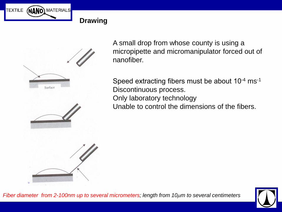
Drawing
A small drop from whose county is using a
micropipette and micromanipulator forced out of
nanofiber.
Speed extracting fibers must be about 10-4 ms-1
Discontinuous process.
Only laboratory technology
Unable to control the dimensions of the fibers.
Fiber diameter from 2-100nm up to several micrometers; length from 10m to several centimeters

Drawing
Appeared in Applied Physics Letters, vol. 89, no.18, pp. 183105-7, 2006
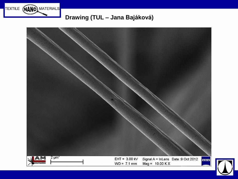
Drawing (TUL – Jana Bajáková)
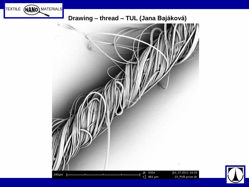
Drawing – thread – TUL (Jana Bajáková)

Drawing - TUL (Jana Bajáková)

Drawing - TUL (Jana Bajáková and Lukáš Stanislav
micromanipulator - VIDEO
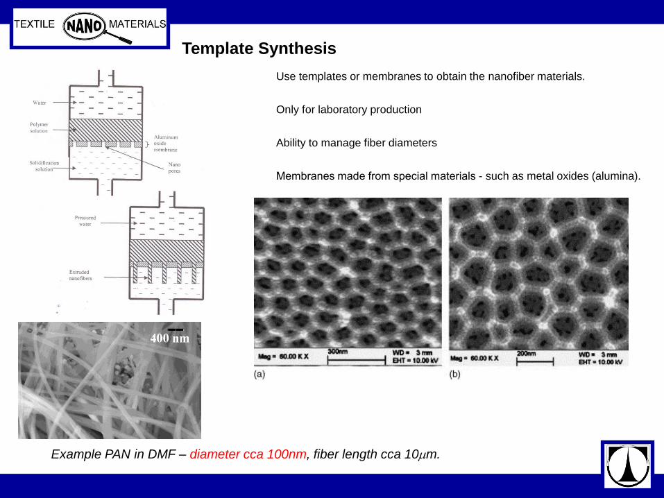
Template Synthesis
Use templates or membranes to obtain the nanofiber materials.
Only for laboratory production
Ability to manage fiber diameters
Membranes made from special materials - such as metal oxides (alumina).
Example PAN in DMF – diameter cca 100nm, fiber length cca 10m.
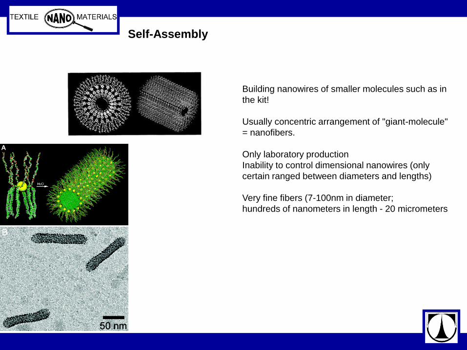
Self-Assembly
Building nanowires of smaller molecules such as in
the kit!
Usually concentric arrangement of "giant-molecule"
= nanofibers.
Only laboratory production
Inability to control dimensional nanowires (only
certain ranged between diameters and lengths)
Very fine fibers (7-100nm in diameter;
hundreds of nanometers in length - 20 micrometers

Phase Separation
The production process Creating a homogeneous solution.
A small amount (2 ml) solution poured into a
teflon container.
Achieving gelation temperature, which depends
on the concentration of polymer in solution.
The solvent was eluted with water.
Remove the gel from the container and dried
using the freeze-drying (freeze-drying).
Eg. it is possible to use polylactic
acid, and the solvent tetrahydrofuran
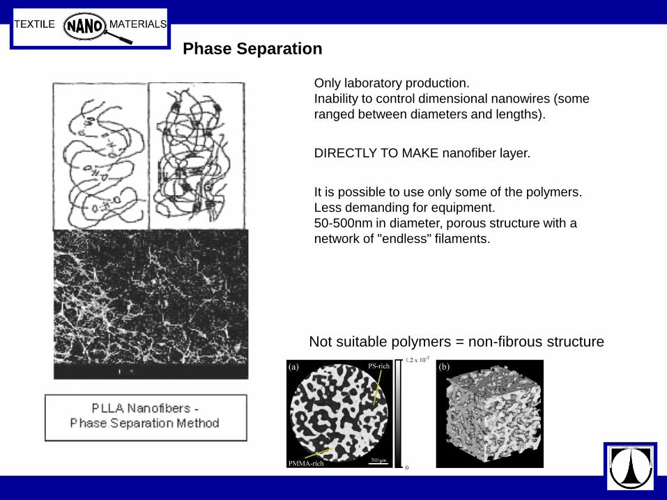
Not suitable polymers = non-fibrous structure
Phase Separation
Only laboratory production.
Inability to control dimensional nanowires (some
ranged between diameters and lengths).
DIRECTLY TO MAKE nanofiber layer.
It is possible to use only some of the polymers.
Less demanding for equipment.
50-500nm in diameter, porous structure with a
network of "endless" filaments.

Melt-blown Technology
http://www.hillsinc.net/nanomeltblownfabric.shtml
Only special types of polymers (eg high MFI polypropylene) - diameter about 250nm;
rather filaments
MFI is usually higher then for microfiber materials production by melt-blown
technology (more then 1000)
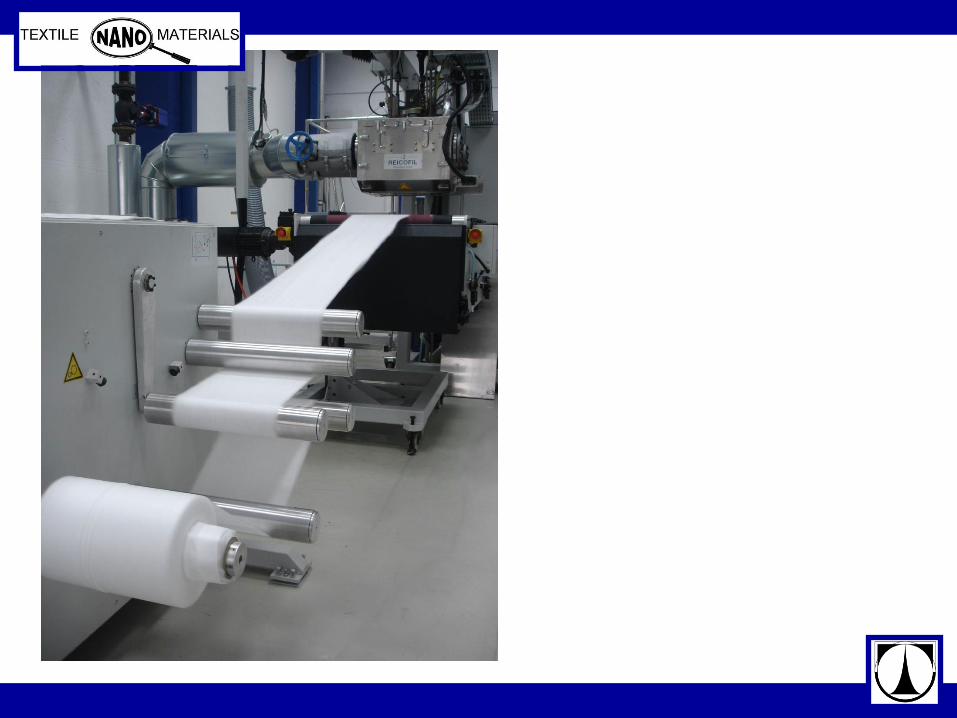
Industrial production
http://www.kasen.co.jp/english/product/line/work.html
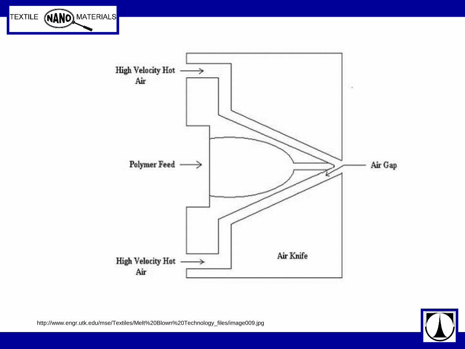
http://www.engr.utk.edu/mse/Textiles/Melt%20Blown%20Technology_files/image009.jpg
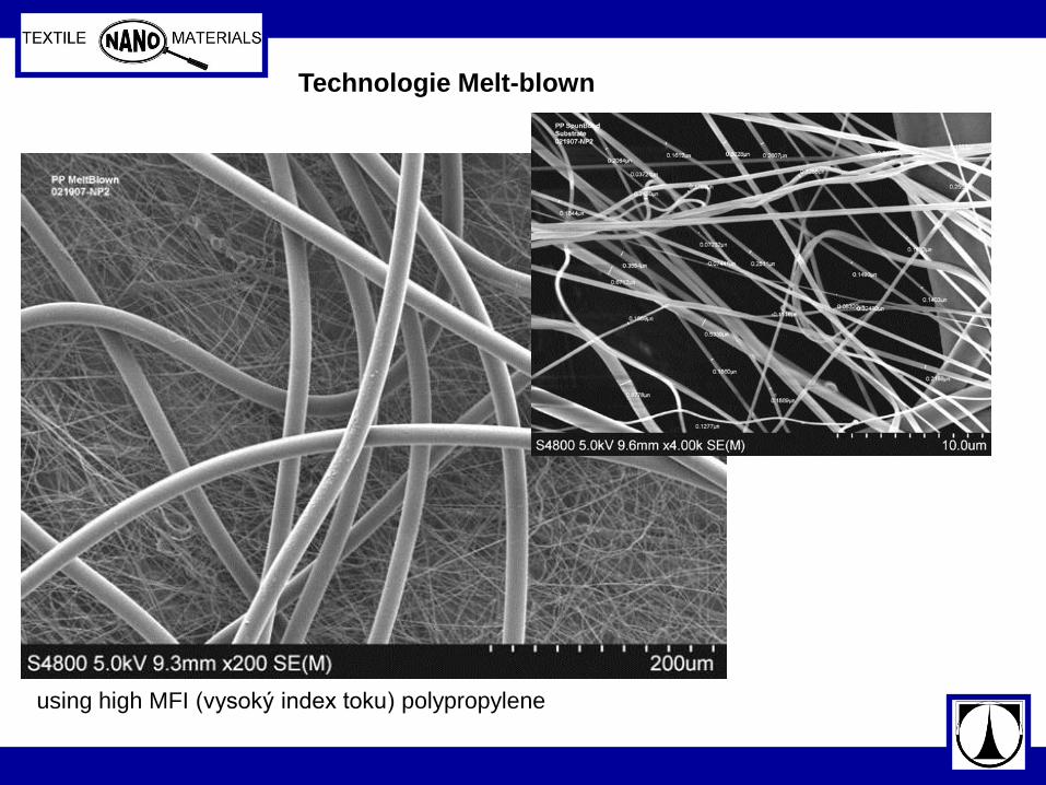
Technologie Melt-blown
using high MFI (vysoký index toku) polypropylene
Meltblowing Another method that Hills, Inc. uses to produce nanofibers involves using a
meltblowing technique. Hills uses a proprietary design to make die with 100 holes
per inch that can be used At 1500 psi. The overall production rate per length of
the spin pack is the same as standard meltblowing. With this technology, the L/D of
the capillaries is increased to 30, and the resulting pressure drop increases from the
standard 40 psi to several hundred psi or greater. As a result, the average melt
blown fiber size is greatly reduced and the rangeof the fiber size is also reduced. In
this technique the spin hole diameters are in the range of 0.10 to 0.15 mm; therefore,
the polymer must have a MFI of 1000 or greater and be extremely clean.
http://www.hillsinc.net/

http://www.kasen.co.jp/english/product/line/work.html
Technologie Melt-blown Technologie Spun-bond
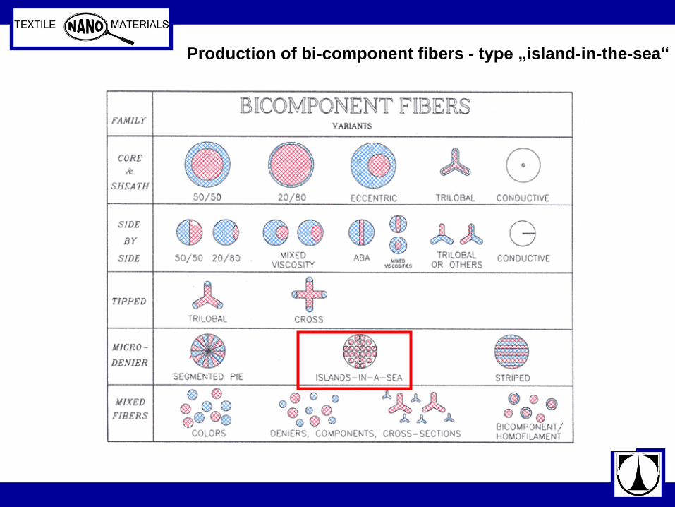
Production of bi-component fibers - type „island-in-the-sea“

cca 500 nm diameter (POP/PVA)
Production of bi-component fibers - type „island-in-the-sea“
Islands-In-The-Sea
One technique that Hills practices to produce nanofibers is done using the
Island-In-The-Sea (fibers within fibers) method. This method, developed
using Hills in-house pilot line, has the capability of making a large number
of fibers within a fiber. The Hills lab has been able to spin up to 1200 fibers
within a single fiber. The Hills’ Islands-In-The-Sea process has the potential
of producing over 4,000 fibers within a single fiber. Using the same
techniques, these filament can be produced as hollow tubes.
http://www.hillsinc.net/
http://www.engr.utk.edu/mse/Textiles/Nanofiber%20Nonwovens.htm
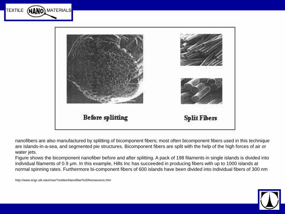
nanofibers are also manufactured by splitting of bicomponent fibers; most often bicomponent fibers used in this technique
are islands-in-a-sea, and segmented pie structures. Bicomponent fibers are split with the help of the high forces of air or
water jets.
Figure shows the bicomponent nanofiber before and after splitting. A pack of 198 filaments in single islands is divided into
individual filaments of 0.9 μm. In this example, Hills Inc has succeeded in producing fibers with up to 1000 islands at
normal spinning rates. Furthermore bi-component fibers of 600 islands have been divided into individual fibers of 300 nm
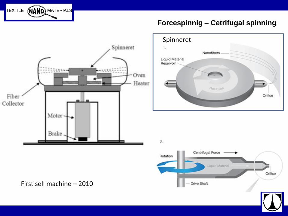
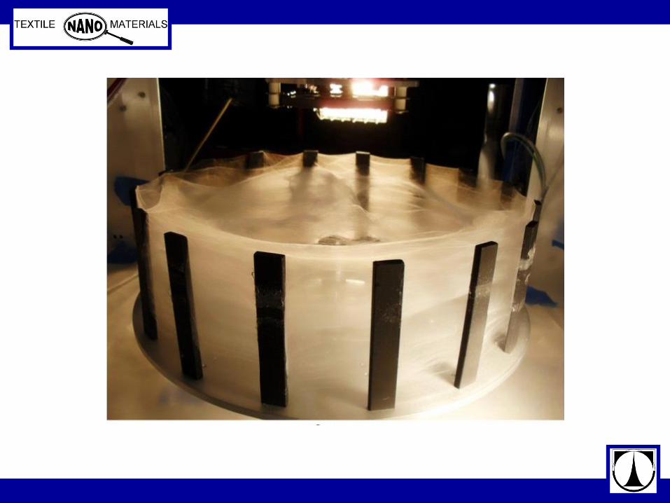
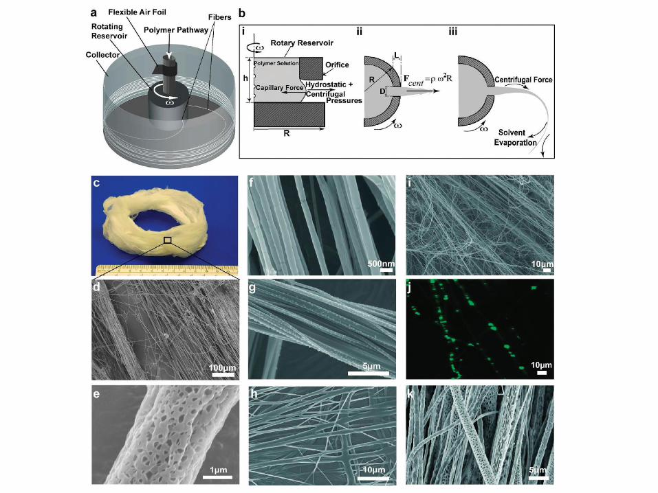
Forcespinnig – Cetrifugal spinning
Spinneret
First sell machine – 2010
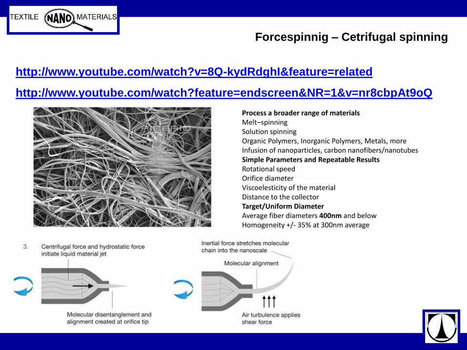
http://www.youtube.com/watch?v=8Q-kydRdghI&feature=related
http://www.youtube.com/watch?feature=endscreen&NR=1&v=nr8cbpAt9oQ
Forcespinnig – Cetrifugal spinning
Process a broader range of materials Melt–spinning Solution spinning Organic Polymers, Inorganic Polymers, Metals, more Infusion of nanoparticles, carbon nanofibers/nanotubes Simple Parameters and Repeatable Results Rotational speed Orifice diameter Viscoelesticity of the material Distance to the collector Target/Uniform Diameter Average fiber diameters 400nm and below Homogeneity +/- 35% at 300nm average
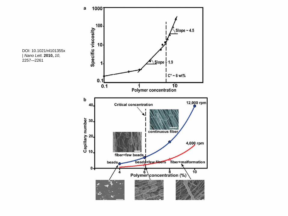
DOI: 10.1021/nl101355x
| Nano Lett. 2010, 10,
2257-–2261

Combination of forcespinning and electrospinning
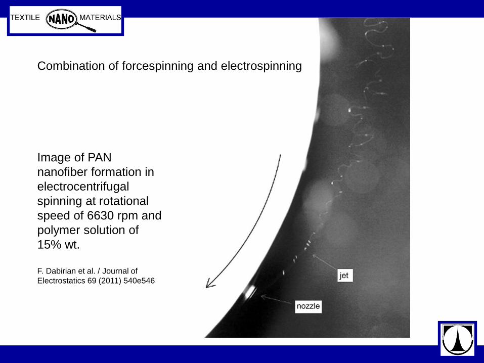
Image of PAN
nanofiber formation in
electrocentrifugal
spinning at rotational
speed of 6630 rpm and
polymer solution of
15% wt.
F. Dabirian et al. / Journal of
Electrostatics 69 (2011) 540e546
Combination of forcespinning and electrospinning
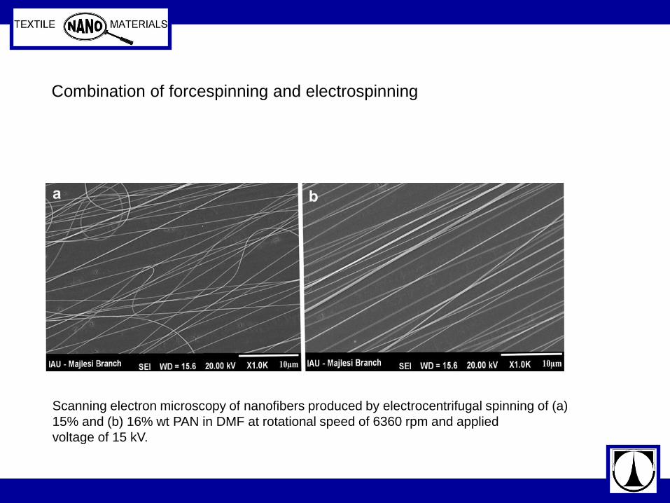
Scanning electron microscopy of nanofibers produced by electrocentrifugal spinning of (a)
15% and (b) 16% wt PAN in DMF at rotational speed of 6360 rpm and applied
voltage of 15 kV.
Combination of forcespinning and electrospinning
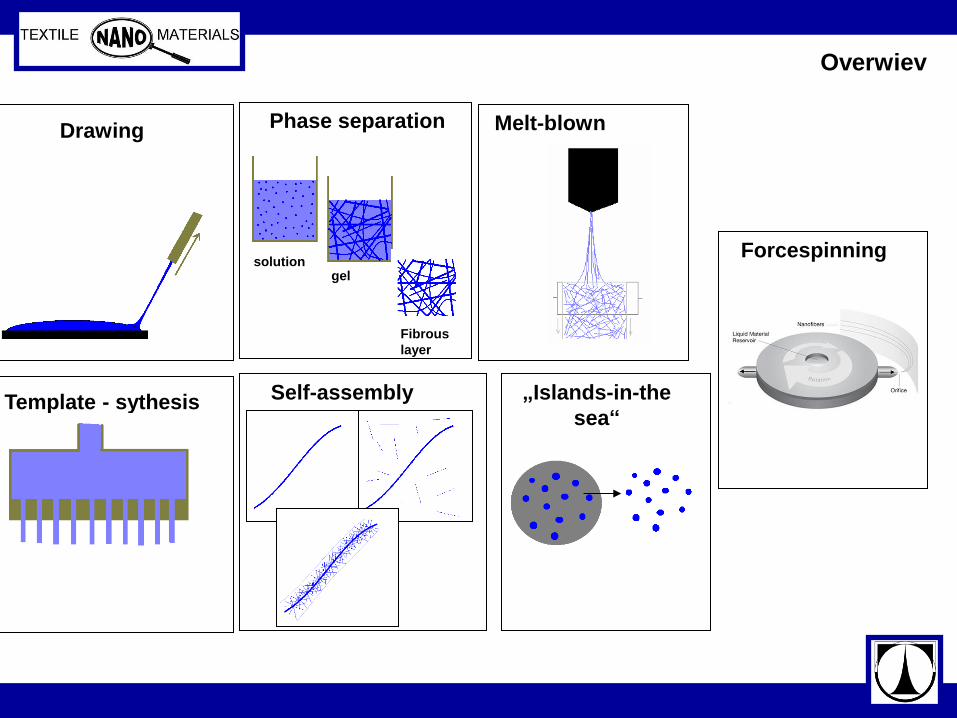
Overwiev
Drawing
Template - sythesis
Phase separation
solution gel
Fibrous
layer
Self-assembly
Melt-blown
„Islands-in-the
sea“
Forcespinning
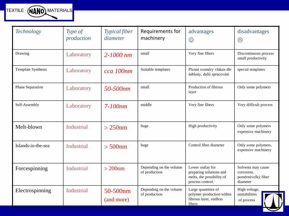
Technology Type of
production
Typical fiber
diameter
Requirements for machinery
advantages
disadvantages
Drawing Laboratory 2-1000 nm small Very fine fibers Discontinuous process
small productivity
Template Synthesis Laboratory
cca 100nm Suitable templates Přesné rozměry vláken dle
šablony, další zpracování
special templates
Phase Separation Laboratory 50-500nm small Production of fibrous
layer
Only some polymers
Self-Assembly Laboratory
7-100nm
middle Very fine fibers Very difficult process
Melt-blown Industrial 250nm huge High productivity Only some polymers
expensive machinery
Islands-in-the-sea Industrial 500nm huge Control fiber diameter Only some polymers,
expensive machinery
Forcespinning Industrial 200nm Depending on the volume
of production
Lower outlay for
preparing solutions and
melts, the possibility of
process control.
Solvents may cause
corrosion,
poměrněvelký fiber
diameter
Electrospinning Industrial 50-500nm
(and more)
Depending on the volume
of production
Large quantities of
polymer production within
fibrous layer, endless
fibers
High voltage,
unstabilities
of process