PC-DMIS 2015.0 Release Notes -...
56
PC-DMIS 2015.0 Release Enterprise Metrology Solutions - Release Notes -
Transcript of PC-DMIS 2015.0 Release Notes -...

PC-DMIS 2015.0 Release Enterprise Metrology Solutions
- Release Notes -

- This page intentionally left blank -

PC-DMIS 2015.0 Release Notes
i
Table of Contents
Recommended System Requirements ....................................................................................... 1
Operating System ................................................................................................................... 1
.NET Framework .................................................................................................................... 1
RAM ....................................................................................................................................... 1
CPU ....................................................................................................................................... 2
Graphics ................................................................................................................................. 2
Hard Drive .............................................................................................................................. 2
Display ................................................................................................................................... 2
Connectivity ............................................................................................................................ 2
Browser .................................................................................................................................. 3
Anti-Virus Software ................................................................................................................. 3
Solutions for CMMs Using RS-232 Communications .............................................................. 3
Installing PC-DMIS ..................................................................................................................... 4
Step 1: Check System and Hardware Requirements .............................................................. 4
Step 2: Log on as an Administrator ......................................................................................... 4
Step 3: Back Up Existing Settings .......................................................................................... 4
Backing Up Machine Files for an Xcel CMM or a Sharpe Controller .................................... 6
Backing Up Machine Files for a CMM with a DEA Controller............................................... 6
Step 4: Install PC-DMIS .......................................................................................................... 7
LMS License Setup ............................................................................................................11
Custom Setup ....................................................................................................................13
Administrator Privileges Explained .....................................................................................14
Step 5: Copy Files after Installation .......................................................................................15
Copying Machine Files for an Xcel CMM or a Sharpe Controller ........................................15
Copying Machine Files for a DEA CMM with a DEA Controller ..........................................15
Step 6: Launch PC-DMIS for the First Time ...........................................................................16
Note About CMMs Using RS-232 Communications ...........................................................18
Updating the Software ...............................................................................................................18
Modifying, Repairing, or Removing the Installation ....................................................................19
Running PC-DMIS in Another Language ...................................................................................19
Installing Non-English Help Files from Language Packs ...........................................................20
Troubleshooting ........................................................................................................................21
PC-DMIS Startup is Slow.......................................................................................................21
Updating the Software Results in a "(407) Proxy Authentication Required" Message ............21
Setting Up the Network to Send Crash Reports .....................................................................21
Installing on Top of an Existing Version Results in Unexpected Behavior ..............................22
Running the Legacy DPUPDATE.EXE Does Not Work .........................................................22
Information about this Release ..................................................................................................23
New Product Information ...........................................................................................................24
2015.0 SP3 Release ..............................................................................................................24
2015.0 SP2 Release ..............................................................................................................24
2015.0 SP1 Release ..............................................................................................................24

PC-DMIS 2015.0 Release Notes
ii
2015.0 Release .....................................................................................................................24
About the PC-DMIS 64-Bit Version ....................................................................................24
Running the PC-DMIS Universal Jogbox Utility ..................................................................25
Release Notes - 2015.0 SP3 .....................................................................................................26
Release Notes - 2015.0 SP2 .....................................................................................................27
Release Notes - 2015.0 SP1 .....................................................................................................30
Release Notes - 2015.0 ............................................................................................................35
Featured Items ......................................................................................................................35
Auto Features ........................................................................................................................40
CAD ......................................................................................................................................40
Execution ..............................................................................................................................41
I++ Server .............................................................................................................................42
Laser / Cloud of Points ..........................................................................................................42
Licensing ...............................................................................................................................42
Machine Interface ..................................................................................................................43
Model Based Definition ..........................................................................................................43
Planner ..................................................................................................................................43
Pointclouds ............................................................................................................................43
Portable .................................................................................................................................43
Probes ...................................................................................................................................43
Reporting ...............................................................................................................................44
Temperature Compensation ..................................................................................................44
Toolkit....................................................................................................................................44
User Interface ........................................................................................................................44
Vision ....................................................................................................................................45
Contact Hexagon Metrology ......................................................................................................46
Appendix A ...............................................................................................................................47
Providing LMS Licensing Information to the Installer from the Command Line .......................47
Appendix B ...............................................................................................................................49
Understanding File Locations ................................................................................................49
Public Documents ..............................................................................................................49
Public Documents (Reporting Directory) ............................................................................49
Public Documents (Fixturing) .............................................................................................49
Program Data Files [Hidden] ..............................................................................................49
User Data Files ..................................................................................................................49
Required User Access Rights ................................................................................................50
File System ........................................................................................................................50
Registry .............................................................................................................................50
Notes .................................................................................................................................50
Appendix C ...............................................................................................................................52
First-Time PC-DMIS Installation with Flexible Fixturing .........................................................52

PC-DMIS 2015.0 Release Notes
1
Recommended System Requirements
Operating System
PC-DMIS 2015.0 operates under the following:
32-bit and 64-bit Vista
32-bit and 64-bit Windows 7
32-bit and 64-bit Windows 8 and 8.1
No other operating systems are supported.
Windows XP support: Beginning with v2012 MR1, support will be phased out for the Windows XP operating system. While this version likely runs fine in XP, it will not be tested under the XP operating system. Also note that some parts of the user interface do not appear optimally in XP. Support will be completely dropped in 2016.
IMPORTANT: When using third-party drivers, you should contact your local Hexagon representative to ensure operating system compatibility.
IMPORTANT: Running PC-DMIS inside a Virtual Machine (VM) is not supported.
Notes:
PC-DMIS Vision machines do not support 32-bit and 64-bit Windows 8.
The Matrox Framegrabber PC-DMIS Vision hardware component does not support a 64-bit operating system.
Advantages of 64-bit:
Customers with the x64-bit version of CAD packages need the 64-bit version of PC-DMIS in order to use Direct CAD Interfaces (DCI) to connect to the packages.
The 64-bit version of PC-DMIS can use all of the physical memory that is available on the computer. The 32-bit version of PC-DMIS can only use the first 2 GB. Therefore, customers with large CAD or measurement routines are advised to use the x64-bit version.
.NET Framework
Microsoft .NET 4.0 for Windows 7
Microsoft .NET 4.5 for Windows 8
RAM
4 GB of RAM or higher (4 GB is the highest amount of memory capable on a 32-bit OS)
The size of the CAD data file and the tessellation multiplier value used affect the amount of memory needed. These both affect the amount of tessellated facets needed to display the model. The smaller the tessellation multiplier value used, the more memory needed for the facets. For large CAD models, this could cause an "Out Of Memory" error. If this occurs, the current PC-DMIS session will be left in an unstable state and should be terminated.

PC-DMIS 2015.0 Release Notes
2
The default tessellation multiplier value is 1.0. Setting a tessellation multiplier of 0.1 will result in a 10 to 20 percent increase in the memory required over the default value of 1.0. Decreasing the tessellation multiplier further to 0.01 will result in an additional 50 to 65 percent increase of memory required.
1 GB of video RAM
CPU
2 GHZ or higher Duo-Core processor
Graphics
For desktops: Nvidia Quadro K620 graphics card
For laptops: Nvidia Quadro K1100M graphics card
The graphics driver must support OpenGL 3.0 or higher. A warning message appears on PC-DMIS startup if the driver does not support OpenGL 3.0 or if your graphics driver is more than a year old.
Hard Drive
2 GB of free hard drive space plus allocated Virtual Memory of 8 times the largest CAD file used
SSD drive, HDD 10K, or two disks in RAID 0 mode (high-performance hard disk drive)
Display
Screen resolution of 1280 x 1024 or higher
Connectivity
2 Ethernet ports. (This may be required for specific installations in consideration of local needs, including but not limited to CMM systems where one port is required for controller communications and another for intranet/Internet communications.)
2 USB ports
DVD drive
HASP key (a physical USB portlock) or a software license
Note: A HASP key does not act as general-purpose data storage; therefore, you cannot use a HASP key to store (download) arbitrary data from a computer. Similarly, you cannot use a HASP key to put (upload) arbitrary data on a computer. Also, only Hexagon Metrology applications can read or write to a HASP key; other applications do not have this capability. As a result, you cannot use a HASP key to load and unload data to and from a computer.

PC-DMIS 2015.0 Release Notes
3
Browser
Internet Explorer version 9
Anti-Virus Software
The Sophos Anti-virus tool was used by Wilcox Associates Inc. while testing PC-DMIS. The performance of any other anti-virus tool will need to be confirmed by the user.
http://sophos.com/products/enterprise/endpoint/security-and-control/
Solutions for CMMs Using RS-232 Communications
If you are installing PC-DMIS on a new or existing computer, but you have an older CMM model that uses RS-232 communications, then you will need to install one of these solutions on your computer:
An external RS-232 serial-to-USB adapter cable plus the serial-to-USB adapter cable driver
An internal serial adapter card with serial ports

PC-DMIS 2015.0 Release Notes
4
Installing PC-DMIS To install the application, follow these steps:
Step 1: Check System and Hardware Requirements
Before you attempt to install a new PC-DMIS version, ensure that you meet the system and hardware requirements discussed above in "Recommended System Requirements". You must also have a USB portlock or a valid software license for the installation to work. Your IT specialist can help you with this information.
To get your computer's properties, highlight the My Computer icon, right-click on it, and select Properties.
To check the display properties for the graphics card, select Start | Settings | Control Panel, and then select Display and Settings.
Step 2: Log on as an Administrator
To install and run your new PC-DMIS version for the first time, you must be logged on as a user with administrator privileges.
Step 3: Back Up Existing Settings
Back up your settings from your previous version. By default, PC-DMIS attempts to migrate existing settings from previous installs on the same computer, even from really old versions of PC-DMIS where settings were stored in the pcdlrn.ini file.
If your current version uses the pcdlrn.ini file for its settings, back up your pcdlrn.ini file. This file is found in the Windows system directory. Save a copy of the file in a safe place.
If your current version uses the PC-DMIS Settings Editor, back up your PC-DMIS Settings Editor data.
To do this:
1. Start the Settings Editor.

PC-DMIS 2015.0 Release Notes
5
2. Click the Backup button (or Export). The Backup dialog box appears:
3. In the File box, define a safe location to save the backed up files, and give the file a .zip extension.
4. Mark the first three check boxes, and click OK.
If you are replacing your computer or transferring settings that reside on another computer, you can use the Settings Editor's Backup and Restore buttons:
For more information on the backup and restore functionality, refer to the Settings Editor documentation.

PC-DMIS 2015.0 Release Notes
6
Backing Up Machine Files for an Xcel CMM or a Sharpe Controller
If you are using a Brown and Sharpe Xcel CMM or a CMM that uses a Sharpe controller, and you are going to install PC-DMIS 2015.0 on a new computer, save copies of the following CMM machine files from your previous version to a safe place:
comp.dat
downl.oad
The files are located in the PC-DMIS installation (root) directory for all versions of PC-DMIS prior to 2013 MR1, regardless of the operating system.
The location of the PC-DMIS installation (root) directory depends on the operating system and version of PC-DMIS:
C:\Program Files (x86)\WAI\PC-DMIS <version> (if you have a 32-bit version)
C:\Program Files\WAI\PC-DMIS <version> (if you have a 64-bit version)
Where <version> is the PC-DMIS version.
For versions of PC-DMIS up to and including 3.7 MR3, the location of the installation (root) directory is:
C:\PCDMISW
Starting with PC-DMIS 2013 MR1, the comp.dat file moved to:
C:\ProgramData\WAI\PC-DMIS\<version>
Backing Up Machine Files for a CMM with a DEA Controller
If you are using a DEA or other CMM with a DEA machine controller, and you are going to install PC-DMIS 2015.0 on a new computer, save copies of the following CMM machine files from your previous version to a safe place (the files vary according to the type of CMM):
cosdat1.bin
compens.dat
Fzyfile.txt
Rcxfile.txt
Rmxfile.txt
Any file with your machine’s serial number in its name
The files are located in the PC-DMIS installation (root) directory for all versions of PC-DMIS prior to PC-DMIS 2013 MR1, regardless of the operating system.
The location of the PC-DMIS installation (root) directory depends on the operating system and version of PC-DMIS:
C:\Program Files (x86)\WAI\PC-DMIS <version> (if you have a 32-bit version)
C:\Program Files\WAI\PC-DMIS <version> (if you have a 64-bit version)
Where <version> is the PC-DMIS version.

PC-DMIS 2015.0 Release Notes
7
For versions of PC-DMIS up to and including 3.7 MR3, the location of the installation (root) directory is:
C:\PCDMISW
Starting with PC-DMIS 2013 MR1, the compens.dat file moved to:
C:\ProgramData\WAI\PC-DMIS\<version>
Step 4: Install PC-DMIS
The following steps run you through a typical installation. Your installation screens may differ if you are running a different version of PC-DMIS. In addition, your PC-DMIS license may be configured with different options.
1. Locate the PC-DMIS install file on your installation media; or, if you downloaded it, open the directory containing the downloaded file. The install file looks like this:
Pcdmis2015.0_Release_#.#.###.#_x##.exe
Where the # symbols represent the specific version numbers and the version type (x64 or x86).
2. Double-click this executable to begin the installation process. If a security warning appears, click Run. The files are extracted to a temporary directory:
The Choose License Type screen appears:

PC-DMIS 2015.0 Release Notes
8
3. Select one of the following license types:
HASP - If you have a physical USB portlock, ensure that it is connected to your computer, and then select this license type. It is selected by default.
LMS (Software) License - If you have been issued a software license (called an Entitlement ID), or if you are connecting to a local license server, select this license type.
Click Next.
4. If you chose HASP, ignore this step, and proceed to step 5. If you chose LMS (Software) License, and it cannot find a valid license on your system, the LMS License Setup screen appears. For help with completing this screen, see "LMS License Setup".
5. The main setup screen then appears:
Click Next. The license agreement appears:

PC-DMIS 2015.0 Release Notes
9
6. Read and accept the license agreement, and then click Next. The Choose Setup Type screen appears:
7. Choose a setup type:
Typical - This option installs the program files to the default installation location: C:\Program Files\WAI\PC-DMIS 2015.0\
Custom - Use this option to specify the components to install and customize the installation location. The Custom Setup screen appears. For help with completing this screen, see "Custom Setup".
8. Once the installation has all the information it needs, the Ready to Install screen appears:

PC-DMIS 2015.0 Release Notes
10
9. Click Install. When the installation finishes, this final screen appears:
Launch PC-DMIS after the install finishes. - To launch the application once you click Finish, select this check box. You should do this so that the needed registry entries are initialized. For more information, see "Administrator Privileges Explained".
Display Release Notes. - To display a PDF file that shows what is new or has changed in this release once you click Finish, select this check box.
10. Click Finish to close the installation program. PC-DMIS is now installed.

PC-DMIS 2015.0 Release Notes
11
LMS License Setup
If you chose LMS (Software) License on the Choose License Type screen, and a valid license cannot be found on your system, you need to fill out the LMS License Setup dialog box:
1. Fill out the LMS License Setup screen as needed:
Use Entitlement ID - If you have an Entitlement ID, select this item, and then type or paste the ID you were issued in the box.
URL to FNO Services - This points to the URL that verifies your license. Ensure that it has this URL:
https://licensing.wilcoxassoc.com/flexnet/services
Proxy Information - You only need to fill this out if you are on a network where a proxy server is needed to reach the Internet. Contact your IT specialist to get this information, and then fill in the server host, user name, and password.
Use License Server(s) - If you are using a local license server, select this item, and then type your license server name. The format of this line of text should be <portnumber>@<servername>, where <portnumber> is the TCP port number for the license server and <servername> is the name of the server. The default TCP port number is 27000, and is used automatically if no specific port number is identified. For example, these mean the same thing:
@server1
27000@server1
Important: When using this option, make sure the "@" symbol is used in front of the server address. If the "@" symbol is left off, the install attempts to look locally for the license which may result in an error.

PC-DMIS 2015.0 Release Notes
12
You can also specify multiple license servers. These are separated by semicolons. For example, suppose that you have three license servers called licenseserver1, licenseserver2, and licenseserver3, all using the default TCP port. You can specify all of them in a single line of text, like this:
@licenseserver1;@licenseserver2;@licenseserver3
2. If you do not have an Entitlement ID and need to activate your license offline, click the CLM Admin button and follow the instructions.
Note: Please consult the PC-DMIS CLM Licensing Software documentation (pcdmisclm.chm) located in the PC-DMIS language subdirectory.
3. Click Next to proceed. The install software connects to the Internet and activates your license. It then installs the FLEXnet Licensing Service required to use LMS licenses.
Providing LMS Licensing Information to the Installer from the Command Line
You can send LMS licensing information to the installer through command line parameters. For more information, see "Providing LMS Licensing Information to the Installer from the Command Line" in Appendix A.
LMS License Update
Once the licensing is completed and PC-DMIS is installed, PC-DMIS checks for license updates on startup and every eight hours of running. If a license update is available, a notification message appears:
PC-DMIS Updates are available for your PC-DMIS license. Applying them now will require PC-DMIS to restart. Would you like to apply the updates now?
Click Yes to apply the update. If you click No, PC-DMIS displays the message every eight hours of running or on the next startup.
If an option or feature is added, you are given the choice to apply the changes. A pop-up message displays in the system tray if you apply the changes.
If an option or feature is removed, a message requesting you to restart PC-DMIS is displayed. A pop-up message also displays in the system tray to inform you of this.
If an option or feature is obsolete, it is automatically removed.
Note: To ensure that PC-DMIS functions properly, you must restart PC-DMIS after any update is applied.

PC-DMIS 2015.0 Release Notes
13
Custom Setup
If you chose Custom on the Choose Setup Type screen, a screen similar to the following appears:
Customizing Installed Features
By default, all program components are selected to be included in the installation. You can use the tree view to customize when or if these features are installed. To do this:
1. Click the small drop-down icon next to the component to exclude. This list appears:
2. Choose the desired option:
Will be installed on local hard drive - The selected feature is installed to the hard drive on your computer.
Entire feature will be installed on local hard drive - The entire feature is installed to the hard drive on your computer. This means that sub-features of the selected feature are also installed.
Will be installed to run from network - This option is currently unsupported. This option installs the selected feature on a network share.
Entire feature will be installed to run from network - This option is currently unsupported. This option installs the entire component to a network share. This means that sub-features of the selected feature are also installed.

PC-DMIS 2015.0 Release Notes
14
Feature will be installed when required - The feature is only installed if required during the installation process. Some files are informational and are not required for the application to run. These may include documentation or other files.
Entire feature will be unavailable - This option excludes the component from installation.
Customizing the Installation Location
By default, the program installs to this location under the "PC-DMIS 2015.0" directory:
C:\Program Files (x86)\WAI\ (if you have a 32-bit version)
C:\Program Files\WAI\ (if you have a 64-bit version)
To change the default location:
1. Click the Browse button and navigate to the directory on your computer that you want to hold the program files. When you click OK, the Location box changes to show the selected location.
If you want to reset the items to the default selection, click Reset.
2. Click Next when you have finished customizing the install.
Administrator Privileges Explained
PC-DMIS versions earlier than version 2012 require that you run PC-DMIS as an administrator because some system settings (such as the last probe used, wrist angles, and other items) were shared among all users on that computer. This required that these settings were placed in the LOCAL_MACHINE section of the Windows registry instead of in the CURRENT_USER section (for user-specific settings). Making changes to settings in the LOCAL_MACHINE section requires administrator privileges.
In PC-DMIS version 2012 and later, the settings mechanism used by PC-DMIS changed to only require administrator access the very first time it runs at the end of the installation. From that point forward, standard user access is sufficient.
The PC-DMIS installer has a flag built into the setup executable (setup.exe) that requires the setup process to run with administrator privileges. If the current user has lesser privileges, the setup displays a prompt to provide a user name and password of an account with administrator privileges.
Once the installation finishes, the first time you run PC-DMIS, you must launch it with administrator privileges. If you mark the Launch PC-DMIS after the install finishes check box when installation finishes, PC-DMIS does this automatically by passing the original privilege level of the installer onto PC-DMIS.
Note, however, that if you do not mark this check box, you will need to explicitly right-click on the shortcut and select Run as administrator as described in Step 6.
For more information on the file system and registry rights that PC-DMIS requires, see "Required User Access Rights" in Appendix B.
PC-DMIS 2015.0 Release Notes
15
Step 5: Copy Files after Installation
If these files are available, copy them from your old PC-DMIS installation directory to the directory where you installed the newer version:
Sysparam.dat
Downl.oad
Fzyfile.txt
Rcxfile.txt
Rmxfile.txt
Starting with PC-DMIS 2010 MR2, PC-DMIS automatically copies common system files to the program data files directory when you install a newer version of PC-DMIS.
The comp.dat, compgrid.at, comp.enc, and compens.dat volcomp files used with volcomp methods 13 (ASI) and 14 (BNS) must be in the program data files directory. When a newer version of PC-DMIS is installed, these files are automatically copied to the program data files directory for the new version. For the default path location of this directory, see "Understanding File Locations" in Appendix B.
For additional information on volumetric compensation files and setup, see the Machine Interface Installation Manual (MIIM).
Copying Machine Files for an Xcel CMM or a Sharpe Controller
If you are using a Brown and Sharpe Xcel CMM or a CMM that uses a Sharpe controller, and you installed PC-DMIS 2015.0 on a new computer, copy the backed-up CMM machine files to the following location on the new computer:
C:\Program Files (x86)\WAI\PC-DMIS <version> (if you have a 32-bit version)
C:\Program Files\WAI\PC-DMIS <version> (if you have a 64-bit version)
Where <version> is the PC-DMIS version.
For more information about these files, see “Backing Up Machine Files for an Xcel CMM or a Sharpe Controller”.
Copying Machine Files for a DEA CMM with a DEA Controller
If you are using a DEA CMM with a DEA machine controller, and you installed PC-DMIS 2015.0 on a new computer, copy the backed-up CMM machine files to the following location on the new computer:
C:\Program Files (x86)\WAI\PC-DMIS <version> (if you have a 32-bit version)
C:\Program Files\WAI\PC-DMIS <version> (if you have a 64-bit version)
Where <version> is the PC-DMIS version.
For more information about these files, see “Backing Up Machine Files for a DEA CMM with a DEA Controller”.

PC-DMIS 2015.0 Release Notes
16
Step 6: Launch PC-DMIS for the First Time
1. When running this version of PC-DMIS for the first time, choose Start, All Programs, and then PC-DMIS 2015.0.
2. From the list of shortcuts, right-click on either the Online or Offline icon, and then select the Run as administrator option (required only if the Launch PC-DMIS after the install finishes check box wasn’t checked at the end of the installation).
3. This allows the program to write the needed machine-specific settings.
If your previous version used the pcdlrn.ini file, PC-DMIS asks if the settings in your PCDLRN.INI file should be used as your registry settings. Click Yes at the prompt. Otherwise, PC-DMIS loads in the factory defaults.
If your previous version used the Settings Editor, do the following to use your previous PC-DMIS settings:
a. Close PC-DMIS.
b. Launch the PC-DMIS Settings Editor from the Start menu.
c. Once it opens, click Import, and open the PCDRegFile.dat file you backed up in the "Step 3: Back Up Existing Settings" section of this document. PC-DMIS imports your settings.
d. Close the PC-DMIS Settings Editor.
For subsequent startups, you can launch PC-DMIS normally by double-clicking the usual Offline or Online shortcut.
PC-DMIS 2015.0 Release Notes
17
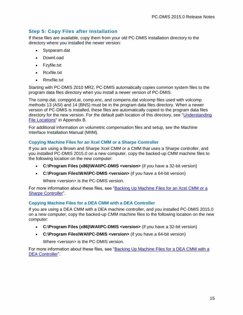
Once PC-DMIS starts, the Software License screen displays the current license agreement. Read the agreement carefully and then at the bottom, click Accept Agreement to proceed:
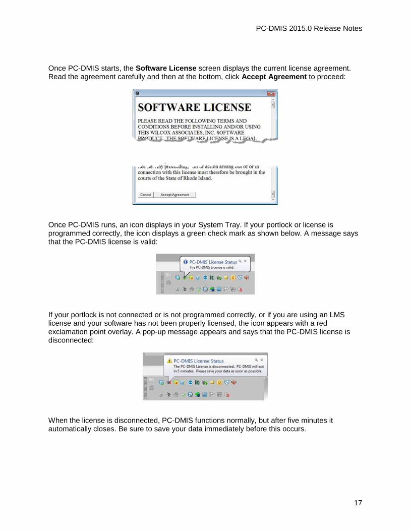
Once PC-DMIS runs, an icon displays in your System Tray. If your portlock or license is programmed correctly, the icon displays a green check mark as shown below. A message says that the PC-DMIS license is valid:
If your portlock is not connected or is not programmed correctly, or if you are using an LMS license and your software has not been properly licensed, the icon appears with a red exclamation point overlay. A pop-up message appears and says that the PC-DMIS license is disconnected:
When the license is disconnected, PC-DMIS functions normally, but after five minutes it automatically closes. Be sure to save your data immediately before this occurs.

PC-DMIS 2015.0 Release Notes
18
Note About CMMs Using RS-232 Communications
By default, PC-DMIS communicates through the COM1 communications port. You need to change this port number to the number that Windows automatically created if a serial-to-USB adapter cable or serial adapter card was installed for communicating with an older RS-232 CMM.
To change the COM port number:
1. In Windows Device Manager, note the number that Windows assigned to the communications port on your computer. For help, refer to Windows Help.
2. Open PC-DMIS in online mode, and then open a measurement routine.
3. Select Edit | Preferences | Machine Interface Setup.
4. In the Comm port box, enter the port number from Windows Device Manager.
Updating the Software By default, PC-DMIS automatically checks for updates to the software if you are connected to the Internet. If it detects that an update is available, the Updates dialog box opens to inform you of the software update. You can then download and install these updates as desired.
You can also manually check for updates by clicking Help | Check for Updates.
If you need information on using the software updater, see "Updating the Software" in the PC-DMIS Core documentation.

PC-DMIS 2015.0 Release Notes
19
Modifying, Repairing, or Removing the Installation You can also modify or repair an installation as needed once it is installed. To do this, double-click on the Pcdmis2015.0_Release_#.#.###.#_x##.exe file as if you were beginning the installation process. The setup displays the Modify, Repair or Remove installation screen with these options:
Modify - This option opens the Custom Setup screen as discussed in "Custom Setup". Use this option to change the installed features, either by adding something that was previously not installed or removing a software feature that you no longer need.
Repair - This option reinstalls all of the product files as they were originally installed. This option may help resolve issues where an installation didn't properly install all of the files.
Remove - This option removes the application from where it was installed. You can also uninstall the application using the Programs and Features control panel item in Control Panel.
Running PC-DMIS in Another Language The initial installation setup file for PC-DMIS contains the user-interface files for all of the supported languages. When you install PC-DMIS, it installs the language files based on your operating system's language.
To run PC-DMIS in a language other than the operating system's language, select File | Language, and then click the desired language.
PC-DMIS restarts and displays the application in the desired language. To get the help content available in a non-English language, see the information below.

PC-DMIS 2015.0 Release Notes
20
Installing Non-English Help Files from Language Packs The English help files are the only help files included in the main installation package. They are installed regardless of the installation language. However, non-English help files are not included in the main installation file.
This means that if you install a non-English language or if you switch to a non-English language, in order to see any help content at all, you must also install a language pack for that language. Otherwise, if you try to access the help file, PC-DMIS displays an error message indicating that it cannot find the help file.
A language pack contains all of the help content for that language.
To install a language pack, do the following:
1. Locate the desired language pack (and .exe file) on your installation media or download it from the Internet here:
ftp://ftp.wilcoxassoc.com/PC-DMIS-Versions/Release/2015.0/Release/Lang
2. Run the .exe file and follow the setup instructions. You do not need to have administrator access to do this step.
This procedure installs the help content into the appropriate two-letter language subdirectory where you have PC-DMIS installed. You can then switch to that language in the software and access the help content.

PC-DMIS 2015.0 Release Notes
21
Troubleshooting This topic provides information for you to troubleshoot installation, startup, and software update problems.
PC-DMIS Startup is Slow
Problem: You use a computer with at least the recommended system requirements as detailed in the "Recommended System Requirements" topic, and it takes longer than 30 seconds to launch PC-DMIS.
Description: This happens if you try to run PC-DMIS on a Windows 7 computer, but you didn't mark Run as administrator on the installation wizard. This results in a problem loading the HASP driver. Note that this problem only occurs when you install with a HASP license type as discussed in "Step 4: Install PC-DMIS".
Solution: Uninstall PC-DMIS, and then reinstall it by right-clicking on the installation file and choosing Run as administrator.
Updating the Software Results in a "(407) Proxy Authentication Required" Message
Problem: You use the Help | Check for Updates menu option to update the software, and when the Web Updater opens, it shows: "The remote server returned an error: (407) Proxy Authentication Required."
Description: A firewall on your computer may be blocking the updater from connecting to the server.
Solution: Check your firewall's settings and ensure that the following address is not blocked: http://www.wilcoxassoc.com/WebUpdater
Setting Up the Network to Send Crash Reports
Problem: PC-DMIS cannot automatically send crash reports to Hexagon Metrology even when the /nocrashdump software configuration switch is not being used. (This switch disables crash reports in PC-DMIS.)
Description: A firewall on your computer may be blocking the updater from connecting to the server. If PC-DMIS crashes, it uses a PHP script over HTTP to send the crash report. If this fails, it then tries to send the report to [email protected]. It tries using the standard SMTP email protocol. If that fails, it tries to send the email through MAPI.
Solution: The crash report system needs to be able to get out to the server, http://www.wilcoxassoc.com/, using port 80.

PC-DMIS 2015.0 Release Notes
22
Installing on Top of an Existing Version Results in Unexpected Behavior
Problem: You installed on top of an existing version of PC-DMIS, and now the software does not behave normally. Potential symptoms include:
After you start up the software, you get a "Procedure Entry Point" error.
When you select Help | About, it does not show the new build number.
Reported bug fixes do not seem to be fixed, and PCDLRN.EXE does not have a newer date and time than the original release.
Description: Something did not install properly on top of the existing version.
Solution: Use Control Panel to completely uninstall the existing version, and then reinstall the version you're trying to install.
Running the Legacy DPUPDATE.EXE Does Not Work
Problem: The legacy DPUPDATE.EXE does not run.
Description: If PC-DMIS is run without administrator privileges, DPUPDATE.EXE does not work.
Solution: Run PC-DMIS with administrator privileges.

PC-DMIS 2015.0 Release Notes
23
Information about this Release We at Hexagon Metrology are proud to bring you this new version of PC-DMIS 2015.0. This Enterprise Metrology Solutions platform brings together new aspects of PC-DMIS for the development of a complete manufacturing process control solution. Available in this release are variations of PC-DMIS designed to assist with every aspect of the fabrication and quality control process. The newly created packages include the established PC-DMIS Laser, PC-DMIS NC, PC-DMIS Pro, PC-DMIS CAD, and PC-DMIS CAD++ platforms.
The testing of this version has been significant. We’d like to take a moment to discuss this process and also make you aware of the various components of testing.
Testing is comprised of two parts. These can be described as functional testing and integration testing. The vast majority of testing effort goes on in the functional area. This is the testing that determines that specific functions that are core to the software, regardless of what type of machine is used, are working correctly. The integration testing is essentially a testing of the interface with a particular type of machine.
In the ideal scenario, Hexagon Metrology would have access to at least one of every piece of hardware that is operating in the field running PC-DMIS. However, in practical terms, this is impossible. This integration test plan is then performed on as many types of machines as we have available.
Should you experience problems with your system after you install PC-DMIS 2015.0, it could possibly be an integration problem. If it is a problem of this nature, it will probably be evident immediately upon first use of the possibly untested configuration. See "Contact Hexagon Metrology" on how to report any integration problems. Should such a problem materialize on a commercial release, you will be given the highest priority for correcting these problems.
For existing users of PC-DMIS who currently have earlier versions of PC-DMIS installed, it is advised that PC-DMIS 2015.0 be installed into a new directory. In this way, you can be assured of continuous use of the existing version should problems arise with this newer version.

PC-DMIS 2015.0 Release Notes
24
New Product Information
2015.0 SP3 Release
Version 2015.0 SP3 is a Service Pack release of the software. For a listing of the enhancements and fixes in this release, refer to "Release Notes - 2015.0 SP3".
2015.0 SP2 Release
Version 2015.0 SP2 is a Service Pack release of the software. For a listing of the enhancements and fixes in this release, refer to "Release Notes - 2015.0 SP2".
2015.0 SP1 Release
Version 2015.0 SP1 is a Service Pack release of the software. For a listing of the enhancements and fixes in this release, refer to "Release Notes - 2015.0 SP1".
2015.0 Release
The 64-bit version of PC-DMIS is only supported on Windows 8.1, Windows 8, Windows 7, and Windows Vista. It is not supported on Windows XP.
For a listing of the enhancements for the 2015.0 Release, refer to "Release Notes - 2015.0". For detailed information and videos tutorials regarding the enhancements, log on to www.pcdmis.com.
About the PC-DMIS 64-Bit Version
The following items are only supported in the 32-bit (x86) version of the software; they are not available in the 64-bit version.
CAD (3D ACIS data embedded inside of DXF Files)
Translators (Avail, Datalog, MeasureMax, MMIV, and Tutor)
NC product line
Vision (MEI, Metronics, QVI, ROI, TESAI++, and TESAVISIO). Note that the FDC and Leitz controllers are available in the 64-bit version.
CMM (B & S Backtalk, Embedded Board, Manmiti, Manmora, Metrocom, Mitutoyo GPIB, GeoCom, GOM, LK, Numerex, Omniman, and anything using the parallel port driver)
Portable (FaroArmUSB and Axila)
ManualCMM and Tech80 have reduced functionalities.

PC-DMIS 2015.0 Release Notes
25
Running the PC-DMIS Universal Jogbox Utility
If you are using the PC-DMIS Universal Jogbox Utility (PCD_UJB_Util.exe *32), ensure that you do the following:
Start the utility as XP-SP2 compatible:
1. Right-click on the PC-DMIS Universal Jogbox Utility icon on your desktop, and then select Properties.
2. Select the Compatibility tab.
3. Select the Run this program in compatibility mode for check box, and then select Windows XP (Service Pack 2) in the list.
4. Select Apply and then OK.
After the utility has been installed, do not run it as an administrator.
Run the utility with the logon account properties that are set for the current user.

PC-DMIS 2015.0 Release Notes
26
Release Notes - 2015.0 SP3 PCD-71600 - Fixed an issue where a machine continued to move after the execution of
the measurement routine was cancelled.
PCD-76383 - If you are using a Leica Tracker interface, PC-DMIS displays a "System Software Mismatch" warning message if the Tracker firmware version does not match the LMF.Tracker.Connection.dll version. The message appears when you start PC-DMIS in online mode and on the System Information tab in the Machine Options dialog box in PC-DMIS Portable.
PCD-76820 - Fixed an issue where the Auto Feature dialog box did not change features when you pressed Shift and clicked on a CAD element.
PCD-77861 - Fixed an issue where the number of rings in a Plane Auto Feature were incorrect when PC-DMIS was updated to a newer version.
PCD-82364 - Fixed an issue where PC-DMIS added hundreds of hits to continuous distance measurements if you used the T-Probe button to start and stop the measurements.
PCD-84088 - Fixed an issue where you could not select the edge points on the borders of a CAD model after you imported a CATIA v5 file.
PCD-84112 - Fixed an issue where PC-DMIS stopped working with the Mitutoyo Bright Direct interface when you calibrated an angle, indicated that the sphere did not move, and then triggered the probe.
PCD-85081 - Fixed an issue where the probe change cycle failed when the wrist angle used was not A0.
PCD-85559 - Fixed an issue where the section cut profile in a measurement routine was incorrect when you opened the measurement routine in a newer version of PC-DMIS.
PCD-86497 - Fixed an issue where PC-DMIS stopped working when you cut a block of commands from the Edit window and then selected Edit | Undo.
PCD-86905 - Fixed an issue where an error did not recover and left the machine in an unstable state.
PCD-87572 - Fixed an error where the section cut profile in a measurement routine with multiple imported CAD files was incorrect when you opened the measurement routine in a newer version of PC-DMIS.
PCD-88020 - Fixed an issue where the BASIC script commands in a measurement routine no longer worked.
PCD-89160 - Fixed an issue where PC-DMIS did not mark a plane feature when you pressed F3 on the MOVE/ROTAB command that referenced the feature.
PCD-90479 - Fixed an issue where the XYZ values and the Digital Readout Unit (DRO) did not change when a Leica AT901 Tracker took hits.
darlene.towne
Highlight
darlene.towne
Highlight
darlene.towne
Highlight
darlene.towne
Highlight
darlene.towne
Highlight
darlene.towne
Highlight
PC-DMIS 2015.0 Release Notes
27
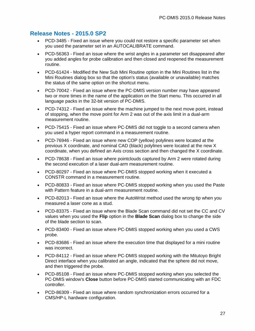
Release Notes - 2015.0 SP2 PCD-3485 - Fixed an issue where you could not restore a specific parameter set when
you used the parameter set in an AUTOCALIBRATE command.
PCD-56363 - Fixed an issue where the wrist angles in a parameter set disappeared after you added angles for probe calibration and then closed and reopened the measurement routine.
PCD-61424 - Modified the New Sub Mini Routine option in the Mini Routines list in the Mini Routines dialog box so that the option's status (available or unavailable) matches the status of the same option on the shortcut menu.
PCD-70042 - Fixed an issue where the PC-DMIS version number may have appeared two or more times in the name of the application on the Start menu. This occurred in all language packs in the 32-bit version of PC-DMIS.
PCD-74312 - Fixed an issue where the machine jumped to the next move point, instead of stopping, when the move point for Arm 2 was out of the axis limit in a dual-arm measurement routine.
PCD-75415 - Fixed an issue where PC-DMIS did not toggle to a second camera when you used a hyper report command in a measurement routine.
PCD-76946 - Fixed an issue where new COP (yellow) polylines were located at the previous X coordinate, and nominal CAD (black) polylines were located at the new X coordinate, when you defined an Axis cross section and then changed the X coordinate.
PCD-78638 - Fixed an issue where pointclouds captured by Arm 2 were rotated during the second execution of a laser dual-arm measurement routine.
PCD-80297 - Fixed an issue where PC-DMIS stopped working when it executed a CONSTR command in a measurement routine.
PCD-80833 - Fixed an issue where PC-DMIS stopped working when you used the Paste with Pattern feature in a dual-arm measurement routine.
PCD-82013 - Fixed an issue where the AutoWrist method used the wrong tip when you measured a laser cone as a stud.
PCD-83375 - Fixed an issue where the Blade Scan command did not set the CC and CV values when you used the Flip option in the Blade Scan dialog box to change the side of the blade section to scan.
PCD-83400 - Fixed an issue where PC-DMIS stopped working when you used a CWS probe.
PCD-83686 - Fixed an issue where the execution time that displayed for a mini routine was incorrect.
PCD-84112 - Fixed an issue where PC-DMIS stopped working with the Mitutoyo Bright Direct interface when you calibrated an angle, indicated that the sphere did not move, and then triggered the probe.
PCD-85108 - Fixed an issue where PC-DMIS stopped working when you selected the PC-DMIS window's Close button before PC-DMIS started communicating with an FDC controller.
PCD-86309 - Fixed an issue where random synchronization errors occurred for a CMS/HP-L hardware configuration.
PC-DMIS 2015.0 Release Notes
28
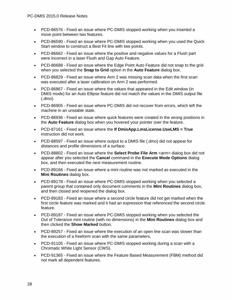
PCD-86576 - Fixed an issue where PC-DMIS stopped working when you inserted a move point between two features.
PCD-86590 - Fixed an issue where PC-DMIS stopped working when you used the Quick Start window to construct a Best Fit line with two points.
PCD-86662 - Fixed an issue where the positive and negative values for a Flush part were incorrect in a laser Flush and Gap Auto Feature.
PCD-86688 - Fixed an issue where the Edge Point Auto Feature did not snap to the grid when you selected the Snap to Grid option in the Auto Feature dialog box.
PCD-86829 - Fixed an issue where Arm 2 was missing scan data when the first scan was executed after a laser calibration on Arm 2 was performed.
PCD-86867 - Fixed an issue where the values that appeared in the Edit window (in DMIS mode) for an Auto Ellipse feature did not match the values in the DMIS output file (.dmo).
PCD-86905 - Fixed an issue where PC-DMIS did not recover from errors, which left the machine in an unstable state.
PCD-86936 - Fixed an issue where quick features were created in the wrong positions in the Auto Feature dialog box when you hovered your pointer over the feature.
PCD-87161 - Fixed an issue where the If DmisApp.LmsLicense.UseLMS = True instruction did not work.
PCD-88597 - Fixed an issue where output to a DMIS file (.dmo) did not appear for distances and profile dimensions of a surface.
PCD-88802 - Fixed an issue where the Select Probe File Arm <arm> dialog box did not appear after you selected the Cancel command in the Execute Mode Options dialog box, and then executed the next measurement routine.
PCD-89166 - Fixed an issue where a mini routine was not marked as executed in the Mini Routines dialog box.
PCD-89178 - Fixed an issue where PC-DMIS stopped working when you selected a parent group that contained only document comments in the Mini Routines dialog box, and then closed and reopened the dialog box.
PCD-89183 - Fixed an issue where a second circle feature did not get marked when the first circle feature was marked and it had an expression that referenced the second circle feature.
PCD-89187 - Fixed an issue where PC-DMIS stopped working when you selected the Out of Tolerance mini routine (with no dimensions) in the Mini Routines dialog box and then clicked the Show Marked button.
PCD-89257 - Fixed an issue where the execution of an open line scan was slower than the execution of a freeform scan with the same parameters.
PCD-91105 - Fixed an issue where PC-DMIS stopped working during a scan with a Chromatic White Light Sensor (CWS).
PCD-91365 - Fixed an issue where the Feature Based Measurement (FBM) method did not mark all dependent features.

PC-DMIS 2015.0 Release Notes
29
PCD-18945 - Fixed an issue where the Use global print settings check box did not appear on the Report tab in the Output Configuration dialog box, and the report did not print according to the output settings, when you opened a measurement routine that you created in a previous version of PC-DMIS.
PC-DMIS 2015.0 Release Notes
30
Release Notes - 2015.0 SP1 PCD-8039, PCD-30349 - Fixed an issue where the "power supply over mains" and other
power display icons did not appear in the Tracker status bar in PC-DMIS Portable if you used the power supply with the Leica AT401.
PCD-23702 - Implemented the Micro-Vu touch probe data analyzer and protocol handler.
PCD-46600 - Fixed an issue where an external command could not execute the QDAS QI Runtime executable file.
PCD-47447 - Fixed conflicts that occurred between an organization's requirement for computer security and the PC-DMIS application's administrative permissions.
PCD-54710 - For B4 and B5 controllers, the current scan setting from the measurement routine will be used instead of the adaptive scan calculations if the Override check box on the adaptive scanning measurement strategy's Advanced tab in the Probe Toolbox is not selected.
PCD-56323 - Fixed an issue where the hits on a mirrored round slot were incorrect when the Read Position check box on the Contact Find Hole Properties tab in the Probe Toolbox was used.
PCD-58170 - Fixed an issue where PC-DMIS did not correctly apply the mapped offset correction to tactile probes.
PCD-61467 - Fixed an issue where PC-DMIS stopped working when GROUP command blocks were copied and pasted between two open measurement routines.
PCD-65151 - Added probe file validation to identify corrupt wrist probe files used in a measurement routine when that measurement routine is opened.
PCD-67123 - Fixed an issue where a scan stopped working when a point reduction filter was used.
PCD-67389 - Fixed an issue where a CMS map could not be created on Arm 2 in a dual-arm measurement routine.
PCD-68948 - Fixed an issue where the PRO and CAD versions of PC-DMIS were not supported in mini routines.
PCD-69111 - Changed the default setting for a laser beam broken event for a Leica Tracker from Go Point to Keep Last Position in PC-DMIS Portable.
PCD-69229 - Updated the configuration server using bootstrap to the latest version (426).
PCD-69513 - Fixed an issue where PC-DMIS imported a tip with a zero diameter when a new tip for a T-probe in Tracker pilot was calibrated.
PCD-69718 - Fixed an issue where a manual scan with a hard probe resulted in incorrect T-values after the measurement routine was executed.
PCD-70704 - Fixed an issue where a refined COP alignment did not work when the measurement routine contained a previous alignment.
PCD-72433 - Fixed an issue where PC-DMIS stopped working when you selected No in the "The video driver date is over a year old." message box.

PC-DMIS 2015.0 Release Notes
31
PCD-73086 - Fixed an issue where the options in the Probe Toolbox in the Auto Feature dialog box were not visible on a high-resolution display.
PCD-73772 - Fixed an issue where the rotary table commands in a measurement routine did not rotate the CAD model when PC-DMIS was in offline mode.
PCD-74212 - Fixed an issue where an "improper argument" error appeared when the initial setup procedure was performed during a new installation.
PCD-74314 - Fixed an issue where PC-DMIS did not execute scan commands in the proper order in a dual-arm measurement routine.
PCD-74710 - Fixed an issue where the deviation on an Auto Vector Point was 0 (zero) if you used a hard probe, selected the Point Only Mode check box on the General tab in the Setup Options dialog box, and measured on a CAD model.
PCD-74774 - Fixed an issue where PC-DMIS shut down while it performed a mirror operation.
PCD-74779 - Fixed an issue where AutoZoom functionality did not work when you exported your printed report or saved your report as a .pdf file.
PCD-74812 - Fixed an issue where the second wrist map replaced the first wrist map when the Create new map option in the Measure Probe dialog box was selected.
PCD-74850 - Fixed a slow processing time that occurred when you exported a COPOPER command in PSL format to a network drive.
PCD-74943 - Fixed an issue where a parallel execution on Arm 2 stopped at every 10 features in a dual-arm measurement routine.
PCD-75206 - Fixed an issue where the hit compensations in a measurement routine were incorrect when PC-DMIS executed two or more features on an arm, changed the probe during the execution, measured the first feature, and then changed the probe again.
PCD-75321 - Fixed an issue where PC-DMIS Portable changed the wrong probe command and did not display a message when it changed probes.
PCD-75713 - Enabled the "Quick Release Open" error message to appear in the status bar and when you open a measurement routine in PC-DMIS Portable for the Leica AT901 and AT960.
PCD-75720 - Fixed an issue with the LMF Tracker interface where PC-DMIS inserted a gravity plane into a measurement routine after the level-to-gravity monitoring process failed.
PCD-75721 - Fixed an issue with the LMS Tracker interface where PC-DMIS automatically started to measure inclination values after the level-to-gravity monitoring process failed.
PCD-75737 - Fixed an issue where PC-DMIS Portable used the last probe in the measurement routine instead of the current probe when it took hits for a different feature.
PCD-75833 - Fixed an issue with the LMF Tracker interface where PC-DMIS Portable could not longer take a measurement after you changed the target type from a reflector to a T-probe and vice versa.

PC-DMIS 2015.0 Release Notes
32
PCD-76382 - Fixed an issue with the LMF Tracker interface where PC-DMIS did not update the tilt values in the digital readout window after you activated the Start Tilt Readout command.
PCD-76822 - Fixed an issue where negative values incorrectly appeared for dimensions in the PDF for a custom report.
PCD-76946 - Fixed an issue where the cross section data was inconsistent after you changed the application point in the dialog box for the cross section.
PCD-76947 - Fixed an issue with the LMS Tracker interface where PC-DMIS was limited to measuring points with 50Hz.
PCD-76988 - Fixed an issue where a blank IP_Default_Parameters message box appeared in all language packs when you selected the default.ipd file in the Modify Default Parameters dialog box, clicked Create, clicked OK in the Default Parameters dialog box, and then clicked Cancel in the Save As dialog box.
PCD-77112 - Fixed an issue where the Blade Scan command did not display the correct point density around a blade section.
PCD-77484 - Fixed an issue where the Notification.dll did not get the proper installation data path in the 64-bit version of PC-DMIS.
PCD-77505 - Fixed an issue where PC-DMIS did not find the nominals on one surface of a part during scanning.
PCD-77537 - Fixed an issue where PC-DMIS incorrectly drew cross-section polylines after the Show Tolerance Lines check box in the Graphical Analysis Options dialog box was cleared.
PCD-77579 - Fixed an issue where a measurement routine with a QuickAlign operation did not generate all of the auto features in the routine when PC-DMIS performed a path optimization.
PCD-77928 - Fixed an issue where CMS incorrectly replaced TIP commands with A0B0.
PCD-78130 - Fixed an issue where the Master Mode dialog box incorrectly reappeared after a Vision measurement routine with a 2D profile feature was saved, closed, and then re-opened.
PCD-78382 - Fixed an issue where embedded media files no longer appeared in the PC-DMIS Message dialog box (for Operator comments) when you closed, reopened, and executed a measurement routine.
PCD-78449 - Fixed an issue where embedded custom reports did not set the update_global_parameters() command when a report was printed during measurement routine execution.
PCD-78540 - Fixed an issue where tolerance values changed when F9 was pressed to edit a dimension and then the Create button was selected instead of the Close button in the Position dialog box.
PCD-78654 - Fixed an issue where PC-DMIS stopped the execution of a measurement routine at a blank COPOPER command.
PCD-78683 - Fixed an issue where the remaining execution time that appeared in the Execution dialog box was incorrect for a laser dual-arm measurement routine.

PC-DMIS 2015.0 Release Notes
33
PCD-78684 - Fixed an issue where PC-DMIS stopped working and did not display an error message when it executed a laser feature extraction command in a dual-arm measurement routine.
PCD-79074 - Fixed an issue where colors did not appear correctly in the distance dimension bar graph.
PCD-79084 - Fixed an issue where a "Can't restore settings from a newer version" error appeared when you performed a backup in Settings Editor v2014 SP3 or v2014.1, and then tried to restore the backup in v2015.0.
PCD-79089 - Fixed an issue where "ALL-TIPS-WITH-DEFAULTS" did not appear in the Parameter set list in the Calibrate Probe dialog box when you selected Insert | Calibrate | AutoCalibrate Probe to insert a new AUTOCALIBRATE/PROBE command.
PCD-79191 - Fixed an issue where point clouds for Auto Surface Points became disabled when you imported a CSV file.
PCD-79240 - Added an algorithm to adjust the analog-output-value for all illumination channels available on the SLC hardware.
PCD-79477 - Fixed an issue where the controller sometimes enabled the probe interface before the probe was loaded when using a probe changer and changing from a camera to a touch-trigger probe. This resulted in a controller-based "probe deflection" error.
PCD-79501 - Added a setting to the Zeiss CMM-OS machine interface that enables you to select an angle by tip number.
PCD-79573 - Fixed an issue where PC-DMIS stopped working when you opened a custom report in the Report window.
PCD-80018 - Fixed an error where the SP25 probe sporadically stopped working and didn't display an error message. This occurred during calibration prior to its first scan.
PCD-80139 - Fixed an issue where CAD elements were not drawn when an XYZ file was imported.
PCD-80212 - Fixed an issue where the box-select method did not create multiple features for an Auto Circle when the Auto Feature dialog box was open.
PCD-80788 - Fixed an issue where a "Missing Toolkit DLL, please contact your vendor." error message appeared when a measurement routine was opened in PC-DMIS v2014.1.
PCD-80844 - Fixed an issue where a feature in an RMEAS reference for a component did not appear in both the Auto Feature dialog box and in the Edit window when the Edit | Paste With Pattern menu option was used to paste the feature into the Edit window.
PCD-81049 - Fixed an issue where PC-DMIS imported a square slot measurement in a DMIS file as a round slot measurement, but displayed the square slot measurement in DMIS format.
PCD-81344 - Fixed an issue where the section views in the Analysis window for a custom report were not at right angles to the cutting plane when a constructed set contained scanned points.
PCD-81368 - Fixed an issue where the 64-bit version of PC-DMIS stopped working if you box-selected a CAD vector point to edit the point.

PC-DMIS 2015.0 Release Notes
34
PCD-81430 - Fixed an issue where you could not view a custom report in the Graphic Display window.
PCD-81750 - Fixed an issue where PC-DMIS added random values to the offline statistics in an .xml file.
PCD-81859 - Fixed an issue where the PC-DMIS Laser feature extractor could not resolve a feature with a depth other than 0 (zero).
PCD-82403 - Fixed an issue where the commands that create, save, and recall an alignment lost their cross-reference relationships when you changed the alignment's text or name in the Edit window.
PCD-82453 - Fixed an issue where PC-DMIS consumed 100% of the CPU and then stopped working for a CMM with an FDC interface.
PCD-82494 - Fixed an issue where Blade Scan control points no longer functioned after you edited their parameters.
PCD-82528 - Fixed an issue where PC-DMIS stopped working when you executed a measurement routine, selected File | Close, and then re-opened the measurement routine.
PCD-83131 - Fixed an issue where PC-DMIS required an unacceptable amount of time to execute a mini routine with marked Feature Based Measurement (FBM) features.
PCD-83141 - Fixed an issue where the Excel output check box on the Excel tab in the Output Configuration dialog box remained selected after you cleared it and re-opened the dialog box.
PCD-83735 - Fixed an issue where PC-DMIS stopped working if you selected File | Close or File | Quit to close or quit a measurement routine after it executed scan commands.
PCD-83858 - Fixed an issue where PC-DMIS randomly displayed an unhandled exception error for PointcloudDll.dll after it measured a laser Auto Feature.
PCD-84024 - Removed Notification Service.
PCD-84167 - Fixed an issue where PC-DMIS 2014.1 SP3 displayed an error message when it processed the adjustheader.exe and copydmofile.exe files while it executed a measurement routine.
PCD-84543 - Fixed an issue where PC-DMIS stopped working when you created a subroutine with the VISION-Image capture command, and then another measurement routine recalled and executed the subroutine.
PCD-84557 - Fixed an issue where PC-DMIS stopped working if you selected the Stop button and then the Skip button in the Execution dialog box during the execution of a VWMP measurement routine.
PCD-84919 - Changed the default value for the ClearanceCubeUsesTipVector
registry entry from 0 to 1. When the value is set to 1, the ClearanceCube uses Tip Vector for Start/End Face check box on the General tab in the Setup Options dialog box is selected for new measurement routines.

PC-DMIS 2015.0 Release Notes
35
Release Notes - 2015.0 Version 2015.0 is a significant development release of the software.
Featured Items
Execution Time Options and Functions
General Setup Options
The following options in the Execution area on the General tab in the Setup Options dialog box (Edit | Preferences | Setup) display the remaining execution time for a measurement routine or mini routine:
Record and display execution time check box - If you select this check box, PC-DMIS displays the remaining execution time (in <hours>:<minutes>:<seconds>) for a measurement routine or mini routine for the new Time Remaining item in the Execution dialog box (File | Execute or File | Partial Execution). Note that:
o PC-DMIS records the remaining time for only the DCC portion of a measurement routine.
o PC-DMIS stops recording the remaining time when the measurement routine or mini routine pauses due to attention required by the user. For example, the execution may pause when a comment is executed, a message appears, or an error appears and the execution stops.
o PC-DMIS does not record the remaining time if the execution does not get completed or if you suspend it.
Add to execution time (seconds) check box - If you select the check box, PC-DMIS adds the number of seconds that you enter (in the related box) to the measurement routine or mini routine execution time when the execution finishes. You may want to use this option if the time required to complete a measurement routine includes other actions in addition to executing the measurement routine or mini routine (such as printing the measurement results).
For more information about these setup options, refer to "Execution Area" and "Using the Execution Dialog Box" in the PC-DMIS Core documentation.
Execution Time Options in Mini Routines Dialog Box
The following options are available on the shortcut menu in the Mini Routines dialog box (File | Partial Execution | Mini Routines):
Show Execution Time - This option displays the execution time in <hours>:<minutes>:<seconds> to the right of the Entire Routine option, the mini routine name, and the sub mini routine name in the rightmost pane of the Mini Routines dialog box.
Update Execution Time - This option updates the execution time after every execution. This update function is available for the entire routine as well as for each separate mini routine. It is selected by default.
For more information, refer to "Mini Routines" in the PC-DMIS Core documentation.

PC-DMIS 2015.0 Release Notes
36
String Functions
These string functions are available:
ELAPSEDEXECUTIONTIME() - This function returns the time that has elapsed since the measurement routine or mini routine started to execute.
LASTEXECUTIONTIME() - This function returns the last execution time that PC-DMIS recorded and stored in the <name of measurement routine>.MiniRoutines.xml file.
For more information, refer to "String Functions" in the PC-DMIS Core documentation.
Gage Scan Calibration Strategy
The Gage Scan Calibration strategy helps you measure the form of a circular feature with the highest possible accuracy. The technical specification for the scanning capability of a CMM defines the terms and concepts that are related to the roundness of individual and integral features. The gage scan filter corrects the measured scan data by comparing it to similar scan data from a gage.
The Gage Scan Calibration strategy calibrates a tip to determine the parameters for the gage scan filter. The strategy scans the inside or outside circle (usually on a ring or plug gage) and determines the filter parameters. These parameters are stored in the probe file (.prb). The calibration results are recorded in the probe’s results file (.Results). The Gage Scan Filter box in the Edit Probe Data dialog box (Insert | Hardware Definition | Probe | Edit button) shows the availability of gage scan data. For more information about this box, refer to "Gage Scan Filter" in the PC-DMIS Core documentation.
Two methods are available for determining the gage scan filter parameters:
Software compensation (for all types of controllers)
Hardware compensation (for B5 and higher Leitz controllers)
These methods are located on the General tab in the Probe Toolbox in the Auto Feature dialog box (Insert | Feature | Auto). For more information, see "Setup Tab - Gage Scan Calibration Strategy" in the PC-DMIS CMM documentation.
The Gage Scan Calibration strategy involves the following steps:
1. Place a ring gage with a diameter that is similar to the diameter on the part with the same orientation close to the position on the machine where the part will be measured.
2. Align this ring gage based on the top surface and the circle.
3. Perform the gage scan calibration after the alignment is complete.
4. After the calibration is complete, use the Adaptive Circle Scan or Adaptive Cylinder Concentric Circle Scan strategy to measure a circle or cylinder.
5. To filter the measured data and calculate the form that is using the data, select the Use Gage Scan Filter check box on the Filters tab in the Probe Toolbox. For more information, see "Enabling the Gage Scan Filter" in the PC-DMIS CMM documentation.
The "Gage Scan Calibration Strategy" topic in the PC-DMIS CMM documentation provides complete information about the strategy, plus an example.

PC-DMIS 2015.0 Release Notes
37
I++ Server Accepts Zeiss A and B Angles Convention
The I++ Server accepts A and B angles, which are reported using Zeiss conventions. This enhancement enables you to use the same program for Zeiss or DEA machines on your client software. It is also compatible with chorus programs.
For complete information about I++ Server, refer to the "PC-DMIS I++ DME Server Setup Guide".
Part Temperature Compensation for Romer Absolute Arm
Part temperature compensation is available for the Romer absolute arm. This feature provides the ability to monitor the part temperature during inspection; it also increases the accuracy of the inspection process. Note that part temperature compensation requires an external temperature sensor.
To enable part temperature compensation, select Insert | Parameter Change | Temperature Compensation. This option inserts the Temperature Compensation command into the measurement routine.
Extended Sheet Metal Options for Auto Features
Extended sheet metal options are available for all contact and laser auto features (except for Corner Point). You can use these options to measure against inspection plans.
To access extended sheet metal options, select the Show Extended Sheet Metal Options check box on the General tab in the Setup Options dialog box (Edit | Preferences | Setup), and then do the following:
1. Select Insert | Feature | Auto and choose an auto feature that supports extended sheet metal options.
2. Select the >> button in the Auto Feature dialog box for Show Extended Sheet Metal Options. This button appears only for supported features.
3. Complete the available options in the Extended sheet metal options area in the Auto Feature dialog box.
For more information, refer to "Extended Sheet Metal Options Area" in the PC-DMIS Core documentation.
Enhanced Laser Data Filter Settings
In PC-DMIS Laser, data filtering allows real-time filtering of the data; the data is removed while scanning. To support this change, the filtering options in the Data Filtering area in the Laser Data Collection Settings dialog box (Operation | Pointcloud | Data Collection) were enhanced as follows:
The Line Filter check box was added. If you select this check box, PC-DMIS sets a real-time filter for individual lines; the filter typically removes scan line noise and results in smoother data. This option also enables you to enter values for the maximum standard deviation and hole length.
The Percent Reduction option was changed to a check box. If you select this check box, PC-DMIS removes a percentage of the pointcloud data that is collected.
The Distance Density option was changed to a check box. This real-time filter provides a filter based on the point distance value that you enter.

PC-DMIS 2015.0 Release Notes
38
For more information about filtering, refer to "Laser Data Collection Settings" in the PC-DMIS Laser documentation.
Improved Mesh Display Quality and Speed
If you select the Mesh option in the Laser Data Collection Settings dialog box in PC-DMIS Laser, laser data appears as a mesh during scanning. The current scan pass displays as a pointcloud, and previous passes display as a mesh. The Mesh display is relative to the orientation of the laser sensor.
While scanning, if the laser sensor orientation changes more than 25 degrees in a single scan pass, PC-DMIS meshes collected data and automatically creates a new patch scan. You can define the displayed mesh by the Grid Size and Max Triangle Size values. After scanning, the data remains displayed as a mesh. When you close and then reopen the PC-DMIS measurement routine, this data appears as a pointcloud.
Mesh display functionality requires the Mesh license. For licensing information, contact your Hexagon Metrology representative.
For more information about mesh functionality, refer to "Laser Data Collection Settings" in the PC-DMIS Laser documentation.
The Mesh option is available only with an LMS license. It also requires the “Big COP” (cloud of points) license option to be enabled.
"Big COP" License Option
The Big COP license option is included for PC-DMIS Laser (but does not include Vision probes). This option provides full pointcloud functionality. The previous COP option (Small COP) limits the number of points in a COP to 500,000. COP is included with PC-DMIS CAD++.
If the Small COP limit is exceeded, the following message appears: “Maximum pointcloud size exceeded, pointcloud will be reduced. Contact your Hexagon Metrology representative to upgrade your license for unlimited pointcloud size.”
For more information about Big COP and Small COP, including differences in functionality between the two license options, see "Using Pointclouds" in the PC-DMIS Laser documentation. For license information, contact your Hexagon Metrology representative.
2D Meshing Management
For a 2D mesh display while scanning in PC-DMIS Laser, when the scanner orientation changes to go around a curved surface (such as a cylinder), PC-DMIS meshes the "patch" in one direction and starts a new patch for the changed direction.
For details about meshing, refer to "Laser Data Collection Settings" in the PC-DMIS Laser documentation.
2D View of Cross Section
When you define a cross section in PC-DMIS Laser, you can display an individual section in a 2D view in the Graphic Display window. This view is normal to the cross section. Any annotation points that are created on the cross section appear in the 2D view.
For complete information, refer to "2D View of Cross Section" in the PC-DMIS Laser documentation.

PC-DMIS 2015.0 Release Notes
39
Simulating Points in a COP in Offline Mode
The new Simulate Pointcloud function enables you to create and view a pointcloud from the Scan dialog box (Insert | Scan | selected scan method) when the CMM is in offline mode. With this feature, you can review the simulated pointcloud and make changes for an individual scan. A COP holds the simulated points.
You can execute the entire measurement routine offline after you create the scans. This displays all of the scans in different probe orientations; it also enables you to check, for example, if you can extract scanned auto features based on the scan settings.
The supported scan methods are:
Linear Open
Patch
Perimeter
Freeform
For details, including an example of using the Simulate Pointcloud function, refer to "Using the Simulate Pointcloud Function" in the PC-DMIS Laser documentation.
Target Mode for Large Auto Features in PC-DMIS Vision
In PC-DMIS Vision, the new Target mode for the Line auto feature locates and measures large auto features in the CAD View and the Live View. When you program with the Live View, this measurement strategy provides measure-as-you-go functionality.
To begin using Target mode for a large auto feature, from the Auto Feature dialog box (Insert | Feature | Auto | Line), in the Probe Toolbox, on the Hit Target tab, click the Large Feature Mode icon. The icon is available only for the Automatic Hit Target type.
For more information about this mode, plus examples that show how to use it in the CAD View and the Live View, refer to "Large Feature Measurement Mode" in the PC-DMIS Vision documentation.

PC-DMIS 2015.0 Release Notes
40
Auto Features
PCD-58987 - Added the DisplayProbePositionAsLastMove registry entry to the
Settings Editor application. This registry entry affects the display of the probe position when you create auto features. If you set the entry to True (the default), the software shows the probe at the last move of the feature path execution. If you set it to False, the software shows the probe at the center of the auto feature (target value).
PCD-58986 - Changed the method for distributing the sample hit pattern for round and square contact slots when you select the Sample Hits option on the Contact Sample Hits Properties tab in the Auto Feature dialog box (Insert | Feature | Auto | Round Slot or Square Slot). PC-DMIS now spaces two of the hits along the same line along the edge of the slot the full length of the slot.
PCD-65403 - Improved the Quick Features functionality to update the Auto Feature dialog box with data from the CAD model in the Graphic Display window based on the mode (Creation mode or Edit mode).
Added "snap to grid" support to the Quick Features functionality for these auto features:
o PCD-54669 - Vector points
o PCD-54670 - Laser edge point
o PCD-67390 - Laser surface point
PCD-63817 - Enabled report vectors, laser/contact auto features, and laser/contact quick
features to automatically update with the feature that you select from the CAD model. This change reduces the time you need to create auto features that report the RT axis on the dimension.
CAD
PCD-56858 - Added functionality that enables you to fix all CAD surface vectors when you import an IGES file:
o Enabled the Fix Surface Vectors button in the CAD Vectors dialog box (Edit | Graphic Display Window | CAD Vectors). Previously, this button was disabled until surfaces were selected. To fix the surface vectors of the entire CAD model, select this button without selecting surfaces. If you select surfaces, then the software fixes only those surface vectors (this is the previous behavior).
o Added the Fix surface vectors check box to the IGES File dialog box (File | Import | IGES | selected IGES file). To fix CAD surface vectors after you import an IGES file, select this check box.
o Added the FixSurfaceVectors registry entry to the Settings Editor application.
This registry entry specifies if the Fix surface vectors check box in the IGES File dialog box is selected (the default) or cleared.
PCD-60015 - Implemented ProE GD&T selection for Direct CAD Interfaces (DCI).
PCD-60224 - Added the Use nothing option to the Edit Rule dialog box for the Rule Tree Editor. If you select this option, PC-DMIS does not display any report information for the item that you defined as a condition. You may find this option useful if you do not want to display anything for a specific feature, command, or condition.

PC-DMIS 2015.0 Release Notes
41
To access the Use nothing option:
1. Select File | Reporting | New | Report Template.
2. Select the TextReportObject object, and insert it into your report template.
3. Right-click on the object, and then click on Rules next to the RuleTree property.
4. In the Rule Tree Editor dialog box, add or edit a rule. The Edit Rule dialog box appears. Note that this dialog box contains the Use nothing control so that you can specifically prohibit information (even default information) from displaying for that rule.
PCD-56062 - Import hidden construction and geometry elements for the CATIA v6 translator. Previously, hidden elements were not imported.
PCD-64328 - Add gesturing so that multiple arc segments can create an arc or circle using Quick Features.
PCD-67314, PCD-66629 - Colored the vectors in the Graphic Display window, and the labels associated with them, in the Auto Feature dialog box (Insert | Feature | Auto). This provides a color-centric way to identify each vector.
For auto features, the vector colors are:
o Blue - Surface
o Green - Edge
o Orange - End angle
o Purple - Start angle
o Red - Angle and line
For Quick Features, the vector colors are:
o Light blue - Surface
o Light green - Edge
o Light red - Angle and line
PCD-66630 - Standardized the vector size for auto features. If the Pt. Size value in the Analysis area in the Auto Feature dialog box is set to 0 (zero), the vectors are a fixed value and do not auto-scale.
PCD-67897 - Added the File | Export | Part Model | CAD Mesh menu option so that you can export a CAD model as a lightweight mesh (as a.cad or .draw file). The export process saves the model's surfaces as triangle meshes instead of mathematical surface definitions.
Execution
PCD-61765, PCD-61763 - Added options and functions that display the execution time for a measurement routine or mini routine. For details, see "Featured Items".
PCD-45885 - Added the ability to select features in the Graphic Display window for execution in a mini routine or sub mini routine.

PC-DMIS 2015.0 Release Notes
42
I++ Server
PCD-61460 - Enabled the I++ Server to accept the A and B angles convention as used by Zeiss/Chorus. For details, see "Featured Items".
PCD-70017 - The last tool used is active at session opening. The I++ Server keeps the last tool used active by default (either by PC-DMIS or by another I++ session), when a StartSession() is performed.
However, if the StartWithUnknownTool registry entry is set to True, Tool.Name() is
reported as “UnknownTool” (as it has been until v3.18 of the I++ Server). The Server version is reported using the command BS_GetVersion().
Laser / Cloud of Points
PCD-63461 - Modified the options in the Data Filtering area in the Laser Data Collection Settings dialog box. For details, see "Featured Items".
PCD-63466 - Improved mesh display quality and speed. For details, see "Featured Items".
PCD-63553 - Meshed the "patch" in one direction and created a new patch for a different direction for a 2D mesh display while scanning. For details, see "Featured Items".
PCD-62479 - Added the ability to display an individual section from a cross section in a 2D view. For details, see "Featured Items".
PCD-64115, PCD-64141, PCD-64194, PCD-64104, PCD-62304, PCD-63766, PCD-63654, PCD-63876, PCD-64525 - Added extended sheet metal options to PC-DMIS Laser auto features. For details, see "Featured Items".
PCD-60006 - Added the ability to create simulated points for offline scan commands. For details, see "Featured Items".
PCD-37978 - Modified the system startup process for PC-DMIS Laser as follows:
o If PC-DMIS is configured for the HP-L-20.8 laser sensor at startup, the system identifies the currently mounted probe.
o If the currently mounted probe is not the HP-L-20.8 laser sensor, and a probe changer is present, the system assumes that the sensor is in the probe changer and switches on the warm-up power state. This helps to ensure that the sensor is warmed and ready for measuring.
Licensing
PCD-70527 - Implemented the ability to automatically toggle from the HASP to the LMS license platform. If you keep your current version of PC-DMIS, this update allows you to change your current license from HASP to LMS. For complete details, see the topic "Client License Manager Software" in the CLM license documentation found in the appropriate language folder of your PC-DMIS installation.

PC-DMIS 2015.0 Release Notes
43
Machine Interface
PCD-33339 - Added support for the Tech80 and manual CMM interfaces to the 64-bit version of PC-DMIS.
For information about operating and configuring the manual CMM interface, refer to the "Manual CMM Interface" document located at:
ftp://files.wilcoxassoc.com/Hardware/CMM/ManualCMM/MANUAL_CMM.pdf
The Tech80 interface is restricted to the Brown & Sharpe CSI USB interface box for a manual CMM. Hardware, interrupt, and OldCaliperDLL settings are not available in the 64-bit version.
Model Based Definition
PCD-59332 - Removed, from the Inspection Plan Default (.ipd) file, parameters that do not apply to Vision features. Added parameters that do apply.
Planner
PCD-39475 - Redesigned Planner so that it uses the latest PC-DMIS technologies. Planner is an independent application that works with PC-DMIS and a CAD software package. Design engineers and quality engineers can use Planner to design an inspection plan that specifies the geometry and GD&T/dimension features to use in the inspection process. They can then import the plan into PC-DMIS, which automatically determines how to efficiently measure it.
For licensing information, contact your Hexagon Metrology representative.
Pointclouds
PCD-41514 - Added the Big COP license option, which provides full pointcloud functionality. For details, see "Featured Items".
Portable
PCD-70731 - Added the Auto End check box to the Quick Start interface (View | Other Windows | Quick Start). If you select the Auto End check box, PC-DMIS automatically finishes or ends a feature in Learn mode after it takes the defined number of hits needed to measure the feature. (You do not need to press any buttons or keys.) You can enter the defined number of hits for each feature type by pressing the Up and Down arrow keys.
Probes
PCD-65952 - Added the HH-A probe head.
PC-DMIS 2015.0 Release Notes
44
PCD-63706 - Please note that some probe types (such as the SP25) do not support Fast Probe mode (Insert | Parameter Change | Probe | Fast Probe Mode). Some machines do not support Fast Probe mode regardless of the probe type. If you have a measurement routine with the FASTPROBEMODE/ON command in it, but your probe type or machine does not support it, the command will not do anything.
Reporting
PCD-50342 - Added the Configure | Dimension Format menu option to the Excel Template Editor (File | Reporting | New | Excel Template). When you open the editor and then select this option, the Properties dialog box appears. You can use the tabs in this dialog box to select the items to add to an Excel template and their order.
PCD-53709 - Added the ability to open multiple Excel Viewers at one time when editing a template (File | Reporting | Edit | Excel Template) or viewing an Inspection Report (View | Inspection Report).
PCD-50334 - Enabled the ability to drag and drop individual items for commands onto an Excel template.
Temperature Compensation
PCD-41375 - Added part temperature compensation to the Romer absolute arm. For details, see "Featured Items".
Toolkit
PCD-32082 - Added the Gage Scan Calibration strategy, which helps you measure the form of a circular feature with the highest possible accuracy. For details, see "Featured Items".
PCD-38065, PCD-53124 - Added options and functions that display the execution time for a measurement routine or mini routine. For details, see "Featured Items".
PCD-42519 - Changed the Blade Nominals Editor command to use low-point density instead of high-point density for partial blade ends.
PCD-61184 - Added the ability to use the Blade COP Section command to section full sections, partial sections, square sections, and skew sections.
PCD-65448 - Replaced the Freeform Plane toolkit module with the Adaptive Free Form Plane Scan strategy. If you open a measurement routine that contains a Freeform Plane toolkit feature, PC-DMIS automatically converts the feature to the Adaptive Free Form Plane Scan strategy.
User Interface
PCD-56240 - Changed the name of the Open dialog box for importing a CAD file (File | Import | CAD) to Import.
PCD-57848 - Added the BRAVO HP 180.16.25-4 and BRAVO HP 60.16.30-2 virtual machines to the machine.dat file.

PC-DMIS 2015.0 Release Notes
45
Vision
PCD-35657 - Added the ability to target and measure large auto features in the CAD View and the Live View. For details, see "Featured Items".

PC-DMIS 2015.0 Release Notes
46
Contact Hexagon Metrology If you are participating in the technical preview of PC-DMIS 2015.0, please post your feedback in the appropriate technical preview forum located at http://www.pcdmisforum.com/forum.php. Please do not contact Technical Support for technical previews.
If you are using the commercially released version of PC-DMIS 2015.0 and would like further information or technical support, please feel free to contact http://hexagonmetrology.us/contact-us or visit www.pcdmis.com. You can also reach Hexagon Metrology Technical Support by calling (1) (800) 343-7933.

PC-DMIS 2015.0 Release Notes
47
Appendix A
Providing LMS Licensing Information to the Installer from the Command Line
You can send LMS licensing information to the installer by using the command line:
If the installer is running in silent mode (/q) or basic silent mode (/qb), and the correct information is provided, everything runs without user interaction. The command switch /qb displays the progress bar and handles installer errors, while the /q switch hides the user interface.
If the installer is not running in silent mode, the information provided is used to populate the LMS activation form and skip the Choose License Type screen.
A description of the parameters follows, along with examples:
USELMSLICENSING="1" - This flag is useful only if the system already has an LMS license that the user is using. It allows silent mode to work without having to prompt the user for a license choice. If the installer is not running in silent mode, it still allows the install process to skip the license type selection dialog (thus saving some time).
ENTITLEMENTID="<entitlement id>" - This parameter and value are useful on a new system where no LMS license was previously installed. It indicates that the user wants LMS licensing and provides an Entitlement ID to try and activate. When this value is specified, there is no need to specify USELMSLICENSING.
LMSLICENSESERVERS="<server1>,<server2>…" - This parameter is used on systems that speak with a license server. It also allows the license type selection dialog box to be skipped and the installation to be done silently.
LMSPROXYHOST="<proxyhostaddress>" - This optional parameter gives the address of a proxy host. In silent mode, it is used directly in activation. In non-silent mode, it populates the activation form with this value.
LMSPROXYUSERNAME="<username>" - This parameter is another optional parameter for the proxy user name. It behaves in the same manner as LMSPROXYHOST.
LMSPROXYPASSWORD="<unencrypted password>" - This parameter is another optional parameter for the proxy password. It behaves in the same manner as LMSPROXYHOST.
LMSFNOURL="<URL to FNO server>" - This parameter is mostly for internal development. The default URL is to the production server. The new value can be used to override the default value and point to the development server.
On a brand-new system with a node locked Entitlement ID, the following line installs PC-DMIS in silent mode:
/qb ENTITLEMENTID="99999-88888-77777-66666-55555"
On a system that already has a license, the following installs PC-DMIS in silent mode:
/qb USELMSLICENSING
On a brand-new system using license servers, the following installs PC-DMIS in silent mode:
/qb LMSLICENSESERVERS="123.12.134.42"

PC-DMIS 2015.0 Release Notes
48
On a brand-new system with no license, the following skips the license type selection dialog box and populates the activation form:
ENTITLEMENTID="99999-88888-77777-66666-55555" LMSPROXYHOST="123.123.123.123" LMSPROXYUSERNAME="bob" LMSPROXYPASSWORD="marley"

PC-DMIS 2015.0 Release Notes
49
Appendix B
Understanding File Locations
The default file locations (path locations) for various user-specific settings and other files have changed in PC-DMIS 2010 MR2 and later to comply with newer operating system standards. Previously, much of this information was stored inside of the install directory of PC-DMIS.
These files are now stored in the following locations for Windows Vista, 7, and 8, based on each file's role (where <version> is the PC-DMIS version).
Public Documents
Measurement routine, CAD, probe, and other files:
C:\Users\Public\Public Documents\WAI\PC-DMIS\<version>
Demo CAD files:
C:\Users\Public\Public Documents\WAI\PC-DMIS\<version>\CAD
Public Documents (Reporting Directory)
Report template, label template, rule definition, and color definition files:
C:\Users\Public\Public Documents\WAI\PC-DMIS\<version>\Reporting
Public Documents (Fixturing)
Fixturing files:
C:\Users\Public\Public Documents\WAI\PC-DMIS\<version>\FIVEUNIQUE
Program Data Files [Hidden]
Calibration files (such as comp.dat and compens.dat), setup files (such as tool.dat, toolc.dat, and usrprobe.dat), and other files:
C:\ProgramData\WAI\PC-DMIS\<version>
User Data Files
Files for toolbar and menu layout, lighting and materials, and settings:
C:\Users\<username>\AppData\Local\WAI\PC-DMIS\<version>
Where <username> is your window's logon user name.
Also see "Understanding the .DAT Files" in the PC-DMIS Core documentation for more specific information on data files.
Note: In addition, functionality was added to the Settings Editor that allows you to back up, restore, or clear user-specific files and settings. Rather than manually deleting or restoring individual files on your own, we recommend that you use the tools provided in the Settings Editor instead. For more information, refer to the Settings Editor documentation.

PC-DMIS 2015.0 Release Notes
50
Required User Access Rights
PC-DMIS requires read, write, and create access to the locations defined below in the file system and registry.
File System
Windows XP
C:\Documents and Settings\All Users\Application Data\WAI\PC-DMIS\2015.0
C:\Documents and Settings\All Users\Documents\WAI\PC-DMIS\2015.0
C:\Documents and Settings\User Name\Local Settings\Application Data\WAI\PC-DMIS\2015.0
Any user-specified folder locations for storing measurement routines, probes, subroutines, and so on
Windows Vista, 7, and 8
C:\ProgramData\WAI\PC-DMIS\2015.0
C:\Users\Public\Documents\WAI\PC-DMIS\2015.0
C:\Users\UserName\AppData\Local\WAI\PC-DMIS\2015.0
Any user-specified folder locations for storing measurement routines, probes, subroutines, and so on
Registry
All of these versions have their own registry settings, which are stored in a version-specific Key. The items shown below are for version 2015.0.
x86 OS
HKEY_LOCAL_MACHINE\SOFTWARE\WAI\PC-DMIS\2015.0 Key and all sub keys
HKEY_CURRENT_USER\Software\WAI\PC-DMIS\2015.0 and all sub keys
HKEY_USERS\.DEFAULT\Software\WAI\PC-DMIS\2015.0 and all sub keys
x64 OS
HKEY_LOCAL_MACHINE\SOFTWARE\Wow6432Node\WAI\PC-DMIS\2015.0 Key and all sub keys
HKEY_CURRENT_USER\Software\WAI\PC-DMIS\2015.0 and all sub keys
HKEY_USERS\.DEFAULT\Software\WAI\PC-DMIS\2015.0 and all sub keys
Notes
The first time you run a new version, PC-DMIS automatically copies the settings from the most recent version of PC-DMIS that is installed. For this to work, PC-DMIS needs to run with administrator privileges the first time you run it. During the installation, if you select the Launch PC-DMIS after the install finishes. check box in the setup wizard, it runs PC-DMIS as an administrator and completes this first step.
This initial migration automatically sets read, write, and create permissions on the registry for the relevant Keys.

PC-DMIS 2015.0 Release Notes
51
If you are using fixturing or laser sensors, the following registry keys are stored back one level:
o HKEY_LOCAL_MACHINE\SOFTWARE\WAI\FxtServer
o HKEY_LOCAL_MACHINE\SOFTWARE\WAI\PC-DMIS\NCSENSORSETTINGS
o It may be easier to just apply create/read/write privileges to the HKEY_LOCAL_MACHINE\SOFTWARE\WAI\ key and all sub keys to cover these also.

PC-DMIS 2015.0 Release Notes
52
Appendix C
First-Time PC-DMIS Installation with Flexible Fixturing
To be compliant with the permission rules for PC-DMIS products, files associated with fixturing are now located in this folder:
C:\Users\Public\Documents\WAI\PC-DMIS\FIVEUNIQUE
This allows access to the files without needing administrator privileges on the computer running PC-DMIS.
To accomplish this, the following steps are required when you install PC-DMIS for the first time:
1. The first time you install PC-DMIS and FxtServerInterface, run the FxtServerInterface installation program for the first time with administrator privileges (as is required for the PC-DMIS install).
2. When running FxtServerInterface, a message states that the system will migrate all your data files to the "FIVEUNIQUE" Documents folder described above.
If you choose "Yes", the files are moved, and the original folder is deleted.
If you choose "No", the files are copied, but the original folder is kept.
Once this is done, the files are moved (or copied), and you are able to run FxtServerInterface.exe without administrator privileges.