PanelView Plus/VersaView CE Terminals and … Manual CD-Components/Allen-Bradley...2 PanelView...
16
Publication 2711P-IN001A-EN-P Installation Instructions PanelView Plus/VersaView CE Terminals and Display Modules (Catalog Numbers 2711P-xxxxxx, 6182H-xxxxxx) English Inside: Overview .............................................................................................................................. 2 For More Information ........................................................................................................... 2 Modular Components .......................................................................................................... 3 Wiring and Safety Guidelines .............................................................................................. 4 Hazardous Locations ............................................................................................................ 5 Environmental Considerations ............................................................................................. 6 Enclosures ............................................................................................................................ 6 Clearances ........................................................................................................................... 6 Required Tools...................................................................................................................... 6 Mounting Dimensions.......................................................................................................... 7 Cutout Dimensions............................................................................................................... 9 Installing Terminal in a Panel............................................................................................. 10 Connecting DC Power ........................................................................................................ 12 European Communities (EC) Directive Compliance ........................................................... 13 Product Specifications ....................................................................................................... 14
Transcript of PanelView Plus/VersaView CE Terminals and … Manual CD-Components/Allen-Bradley...2 PanelView...
Installation Instructions
PanelView Plus/VersaView CE Terminals and Display Modules(Catalog Numbers 2711P-xxxxxx, 6182H-xxxxxx)
English
Inside:
Overview ..............................................................................................................................2For More Information ...........................................................................................................2Modular Components ..........................................................................................................3Wiring and Safety Guidelines..............................................................................................4Hazardous Locations ............................................................................................................5Environmental Considerations .............................................................................................6Enclosures ............................................................................................................................6Clearances ...........................................................................................................................6Required Tools......................................................................................................................6Mounting Dimensions..........................................................................................................7Cutout Dimensions...............................................................................................................9Installing Terminal in a Panel............................................................................................. 10Connecting DC Power ........................................................................................................ 12European Communities (EC) Directive Compliance ........................................................... 13Product Specifications ....................................................................................................... 14
Publication 2711P-IN001A-EN-P

2 PanelView Plus/VersaView CE Terminals and Display Modules
OverviewThis document provides instructions on how to install the following devices in a panel or enclosure.
• factory assembled PanelView Plus or VersaView CE terminal
• PanelView Plus or VersaView CE Display Module
Refer to the installation instructions shipped with the Logic Module and Communiction Module for field installation of these components.
For More InformationTo obtain electronic versions of the PanelView Plus or VersaView CE User Manual, visit the following web sites:
• www.theautomationbookstore.com
• www.ab.com/manuals
Publication 2711P-IN001A-EN-P

PanelView Plus/VersaView CE Terminals and Display Modules 3
Modular ComponentsThe PanelView Plus and VersaView CE terminals have the following modular components:
• Display Module (700/700H, 1000/1000H, 1250/1250H, 1500/1500H)
• Logic Module (DC Power, CF Card Slot, Ethernet Port, Serial Port, USB Ports)
• Internal Compact Flash card with firmware or operating system, RAM Memory (SO-DIMM)
• Communication Module (for specific communication protocols)
These items can be ordered as separate components for field installation or factory assembled per your configuration. The base configured unit includes the Display Module and the Logic Module (with Internal Compact Flash and RAM).
If the modules are ordered separately, attach the Logic Module and Communication Module) to the Display Module before panel installation. See instructions shipped with each module.
The VersaView CE terminal is shipped with RAM and Compact Flash pre-installed in Logic Module. The RAM and Compact Flash are not pre-installed in the Logic Module of the PanelView Plus. You must install the memory before attaching the Logic Module to Display Module. See instructions shipped with Logic Module.
Communication Module
Logic Module
Display Module
DC Power Input
Ethernet PortSerial PortUSB PortsCompact Flash Card Slot
Publication 2711P-IN001A-EN-P

4 PanelView Plus/VersaView CE Terminals and Display Modules
Wiring and Safety GuidelinesUse publication NFPA 70E, Electrical Safety Requirements for Employee Workplaces when wiring the terminals. In addition to the NFPA guidelines:
• connect the terminal and other similar electronic equipment to its own branch circuit
• protect the input power by a fuse or circuit breaker rated at no more than 15 Amps.
• route incoming power to the terminal by a separate path from the communication lines.
• where power and communication lines must cross, they should cross at right angles. Communication lines can be installed in the same conduit as low level DC I/O lines (less than 10 volts).
• grounding minimizes noise from Electromagnetic Interference (EMI) and is a safety measure in electrical installations. To avoid EMI, shield and ground cables appropriately.
A source for grounding recommendations is the National Electrical Code published by the National Fire Protection Association of Boston.
Publication 2711P-IN001A-EN-P

PanelView Plus/VersaView CE Terminals and Display Modules 5
Publication 2711P-IN001A-EN-P
Hazardous LocationsThis equipment is suitable for:
• Class I, Division 2 Groups A, B, C, D• Class II, Division 2 Groups F, G• Class III Division 1 • or non-hazardous locations only
The following statement applies to use in hazardous locations.
The PanelView Plus and VersaView CE terminals have an operating temperature code of T4 (maximum operating temperature of 55 °C or 131 °F). Do not install the terminals in environments where atmospheric gases have ignition temperatures less than 55 °C or 131 °F.
WARNING
!Explosion Hazard
• Substitution of components may impair suitability for hazardous locations.
• Do not disconnect equipment unless power has been switched off and area is known to be non-hazardous.
• Do not connect or disconnect components unless power has been switched off.
• All wiring must comply with N.E.C. articles 501-4(b), 502-4(b), 503-3(b) as appropriate.
• Peripheral equipment must be suitable for the location it is used in.
6 PanelView Plus/VersaView CE Terminals and Display Modules
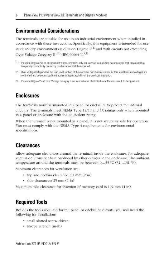
Environmental ConsiderationsThe terminals are suitable for use in an industrial environment when installed in accordance with these instructions. Specifically, this equipment is intended for use
in clean, dry environments (Pollution Degree 2(1) and with circuits not exceeding
Over Voltage Category II (2) (IEC 60664-1).(3)
(1) Pollution Degree 2 is an environment where, normally, only non-conductive pollution occurs except that occasionally a temporary conductivity caused by condensation shall be expected.
(2) Over Voltage Category II is the load level section of the electrical distribution system. At this level transient voltages are controlled and do not exceed the impulse voltage capability of the product’s insulation.
(3) Pollution Degree 2 and Over Voltage Category II are International Electrotechnical Commission (IEC) designations.
EnclosuresThe terminals must be mounted in a panel or enclosure to protect the internal
circuitry. The terminals meet NEMA Type 12/13 and 4X ratings only when mounted in a panel or enclosure with the equivalent rating.
When the terminal is not mounted in a panel, it is not secure or safe for operation. You must comply with the NEMA Type 4 requirements for environmental specifications.
ClearancesAllow adequate clearances around the terminal, inside the enclosure, for adequate ventilation. Consider heat produced by other devices in the enclosure. The ambient temperature around the terminals must be between 0…55 °C (32…131 °F).
Minimum clearances for ventilation are:
• top and bottom clearance: 51 mm (2 in)
• side clearances: 25 mm (1 in)
Maximum side clearance for insertion of memory card is 102 mm (4 in).
Required ToolsBesides the tools required for the panel or enclosure cutouts, you will need the following for installation:
• small slotted screw driver
• torque wrench (in-lb)
Publication 2711P-IN001A-EN-P

PanelView Plus/VersaView CE Terminals and Display Modules 7
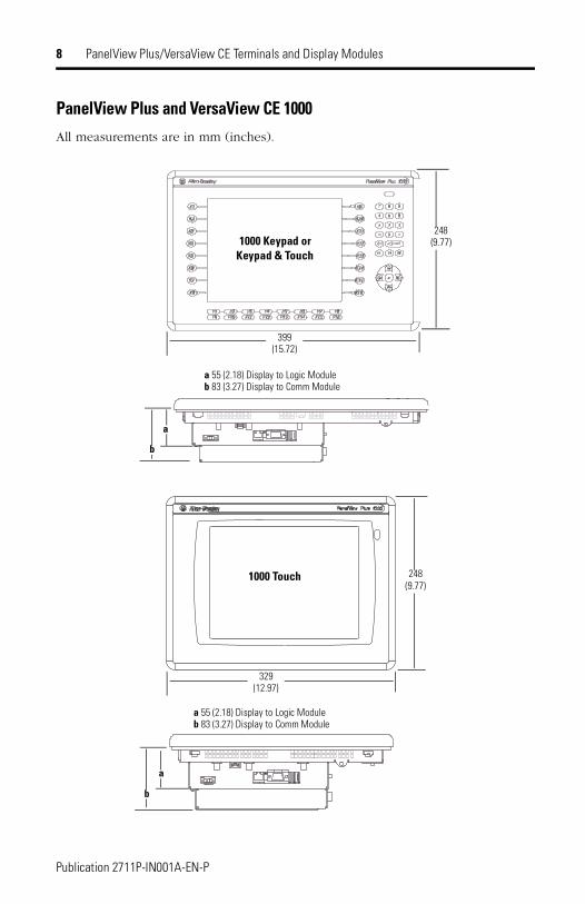
Mounting DimensionsThis section provides mounting dimensions for the PanelView Plus and VersaView CE terminals. The depth dimensions are shown for the:
• base unit including Display Module and Logic Module
• base unit with Communication Module
All measurements are in mm (inches).
The illustration following the table shows dimensions for the 1000/1000H terminals.
Terminal Type Height Width Depth
PanelView Plus 700/VersaView CE 700HKeypad orKeypad & Touch
193 (7.58) 290 (11.40)
55 (2.18) Display to Logic Module83 (3.27) Display to Comm Module
PanelView Plus 700/VersaView CE 700HTouch Screen
179 (7.04) 246 (9.68)
PanelView Plus 1000/VersaView CE 1000HKeypad orKeypad & Touch
248 (9.77) 399 (15.72)
PanelView Plus 1000/VersaView CE 1000H Touch Screen
248 (9.77) 329 (12.97)
PanelView Plus 1250/VersaView CE 1250HKeypad or Keypad & Touch
282 (11.12) 416 (16.36)
PanelView Plus 1250/VersaView CE 1250HTouch Screen
282 (11.12) 363 (14.30)
PanelView Plus 1500/VersaView CE 1500H Keypad or Keypad & Touch
330 (12.97) 469 (18.46) 65 (2.55) Display to Logic Module93 (3.65) Display to Comm ModulePanelView Plus 1500/VersaView CE 1500H
Touch Screen330 (12.97) 416 (16.36)
Publication 2711P-IN001A-EN-P
8 PanelView Plus/VersaView CE Terminals and Display Modules
PanelView Plus and VersaView CE 1000All measurements are in mm (inches).
1000 Keypad or Keypad & Touch
1000 Touch
a 55 (2.18) Display to Logic Moduleb 83 (3.27) Display to Comm Module
a 55 (2.18) Display to Logic Moduleb 83 (3.27) Display to Comm Module
248(9.77)
399(15.72)
b
a
b
a
329(12.97)
248(9.77)
Publication 2711P-IN001A-EN-P
PanelView Plus/VersaView CE Terminals and Display Modules 9
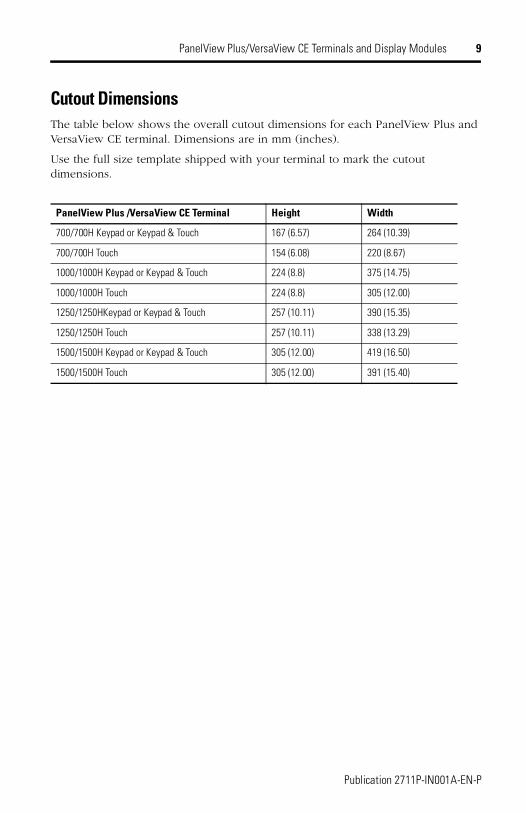
Cutout DimensionsThe table below shows the overall cutout dimensions for each PanelView Plus and VersaView CE terminal. Dimensions are in mm (inches).
Use the full size template shipped with your terminal to mark the cutout dimensions.
PanelView Plus /VersaView CE Terminal Height Width
700/700H Keypad or Keypad & Touch 167 (6.57) 264 (10.39)
700/700H Touch 154 (6.08) 220 (8.67)
1000/1000H Keypad or Keypad & Touch 224 (8.8) 375 (14.75)
1000/1000H Touch 224 (8.8) 305 (12.00)
1250/1250HKeypad or Keypad & Touch 257 (10.11) 390 (15.35)
1250/1250H Touch 257 (10.11) 338 (13.29)
1500/1500H Keypad or Keypad & Touch 305 (12.00) 419 (16.50)
1500/1500H Touch 305 (12.00) 391 (15.40)
Publication 2711P-IN001A-EN-P
10 PanelView Plus/VersaView CE Terminals and Display Modules
Installing Terminal in a PanelAll of the PanelView Plus and VersaView CE terminals are installed in the same manner using clips for mounting. The number of clips used (4, 6 or 8) varies by terminal type. The mounting clips are shipped with each terminal.
To install a terminal in a panel:
1. Cut an opening in the panel using the panel cutout provided with the terminal. Remove any sharp edges or burrs.
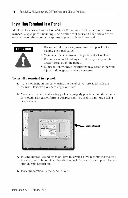
2. Make sure the terminal sealing gasket is properly positioned on the terminal as shown. This gasket forms a compression type seal. Do not use sealing compounds.
3. If using keypad legend strips on keypad terminals, we recommend that you install the strips before installing the terminal. Be careful not to pinch legend strip during installation.
4. Place the terminal in the panel cutout.
ATTENTION
!• Disconnect all electrical power from the panel before
making the panel cutout.
• Make sure the area around the panel cutout is clear.
• Do not allow metal cuttings to enter any components already installed in the panel.
• Failure to follow these instructions may result in personal injury or damage to panel components.
Sealing Gasket
Publication 2711P-IN001A-EN-P
PanelView Plus/VersaView CE Terminals and Display Modules 11
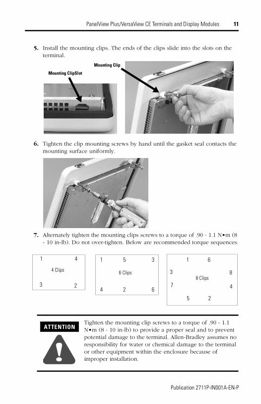
5. Install the mounting clips. The ends of the clips slide into the slots on the terminal.
6. Tighten the clip mounting screws by hand until the gasket seal contacts the mounting surface uniformly.
7. Alternately tighten the mounting clips screws to a torque of .90 - 1.1 N•m (8 - 10 in-lb). Do not over-tighten. Below are recommended torque sequences.
ATTENTION
!Tighten the mounting clip screws to a torque of .90 - 1.1 N•m (8 - 10 in-lb) to provide a proper seal and to prevent potential damage to the terminal. Allen-Bradley assumes no responsibility for water or chemical damage to the terminal or other equipment within the enclosure because of improper installation.
Mounting ClipSlot
Mounting Clip
8 Clips
1
2
3
4
5
6
7
86 Clips
24 6
51 3
4 Clips
1 4
3 2
Publication 2711P-IN001A-EN-P
12 PanelView Plus/VersaView CE Terminals and Display Modules
Connecting DC PowerThe PanelView Plus and VersaView CE terminals have an integrated power supply that operates on 24V dc. The electrical input ratings of the power supply are:
• 24V dc nominal (18…32V dc)
• 70 Watts maximum (2.9A @24V dc)
The power supply is internally protected against reverse polarity.
The input power, terminal block on the power supply is removable and supports the following wire sizes:
The terminals using 24V dc power are EN 61131-2 Equipment Class II devices.
To connect DC power:
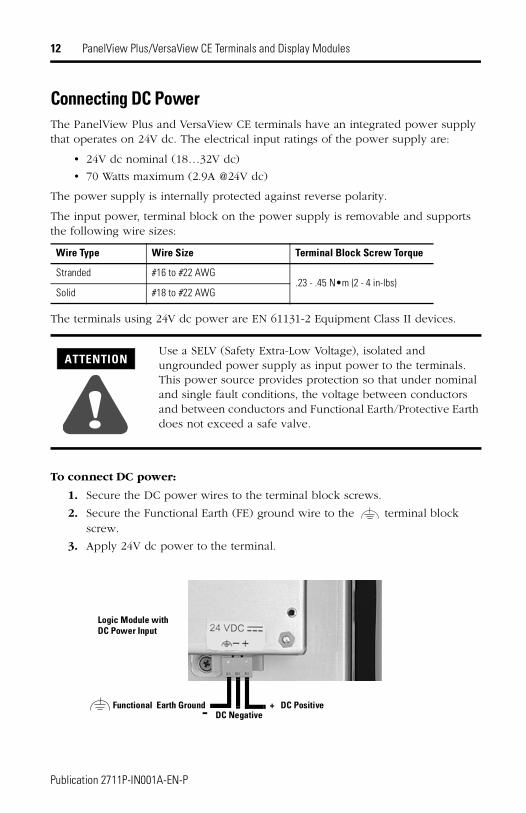
1. Secure the DC power wires to the terminal block screws.
2. Secure the Functional Earth (FE) ground wire to the terminal block screw.
3. Apply 24V dc power to the terminal.
Wire Type Wire Size Terminal Block Screw Torque
Stranded #16 to #22 AWG.23 - .45 N•m (2 - 4 in-lbs)
Solid #18 to #22 AWG
ATTENTION
!Use a SELV (Safety Extra-Low Voltage), isolated and ungrounded power supply as input power to the terminals. This power source provides protection so that under nominal and single fault conditions, the voltage between conductors and between conductors and Functional Earth/Protective Earth does not exceed a safe valve.
Functional Earth Ground- DC Negative+ DC Positive
Logic Module with DC Power Input
Publication 2711P-IN001A-EN-P
PanelView Plus/VersaView CE Terminals and Display Modules 13
European Communities (EC) Directive ComplianceIf this product has the CE mark it is approved for installation within the European Union and EEA regions. It has been designed and tested to meet the following directives.
EMC DirectiveThis product is tested to meet the Council Directive 89/336/EC Electromagnetic Compatibility (EMC) by applying the following standards, in whole or in part, documented in a technical construction file:
• EN 50081-2 EMC - Generic Emission Standard, Part 2 - Industrial Environment
• EN 61000-6-2 EMC - Generic Immunity Standard, Part 2 - Industrial Environment
This product is intended for use in an industrial environment.
Low Voltage DirectiveThis product is tested to meet Council Directive 73/23/EEC Low Voltage, by applying the safety requirements of EN 61131-2 Programmable Controllers, Part 2 - Equipment Requirements and Tests. For specific information required by EN 61131-2, see the appropriate sections in this publication, as well as the Allen-Bradley publication Industrial Automation Wiring and Grounding Guidelines For Noise Immunity, publication 1770-4.1.
Open style devices must be provided with environmental and safety protection by proper mounting in enclosures designed for specific application conditions. See NEMA Standards publication 250 and IEC publication 529, as applicable, for explanations of the degrees of protection provided by different types of enclosure.
Publication 2711P-IN001A-EN-P
14 PanelView Plus/VersaView CE Terminals and Display Modules
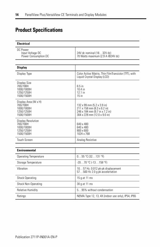
Product Specifications
Electrical
DC PowerInput Voltage DCPower Consumption DC
24V dc nominal (18… 32V dc)70 Watts maximum (2.9 A @24V dc)
Display
Display Type Color Active Matrix, Thin FilmTransistor (TFT), with Liquid Crystal Display (LCD)
Display Size700/700H1000/1000H1250/1250H1500/1500H
6.5 in10.4 in12.1 in15 in
Display Area (W x H)700/700H1000/1000H1250/1250H1500/1500H
132 x 99 mm (5.2 x 3.9 in)211 x 158 mm (8.3 x 6.2 in)246 x 184 mm (9.7 in x 7.2 in)304 x 228 mm (12.0 x 9.0 in)
Display Resolution700/700H1000/1000H1250/1250H1500/1500H
640 x 480640 x 480800 x 6001024 x 768
Touch Screen Analog Resistive
Environmental
Operating Temperature 0…55 °C (32…131 °F)
Storage Temperature -20…70 °C (-13…158 °F)
Vibration 10… 57 Hz, 0.012 pk-pk displacement57…500 Hz 2.0 g pk accelertation
Shock Operating 15 g at 11 ms
Shock Non-Operating 30 g at 11 ms
Relative Humidity 5…95% without condensation
Ratings NEMA Type 12, 13, 4X (indoor use only), IP54, IP65
Publication 2711P-IN001A-EN-P

PanelView Plus/VersaView CE Terminals and Display Modules 15
Mechanical
Dimensions H x W x D (for base configured unit without communication module)
700/700H Keypad or Keypad & Touch 193 x 290 x 55 mm (7.58 x 11.40 x 2.18 in)
700/700H Touch 179 x 246 x 55 mm (7.04 x 9.68 x 2.18 in)
1000/1000H Keypad or Keypad & Touch 248 x 399 x 55 mm (9.77 x 15.72 x 2.18 in)
1000/1000H Touch 248 x 329 x 55 mm (9.77 x 12.97 x 2.18 in)
1250/1250H Keypad or Keypad & Touch 282 x 416 x 55 mm (11.12 x 16.36 x 2.18 in)
1250/1250H Touch 282 x 363 x 55 mm (11.12 x 14.30 x 2.18 in)
1500/1500H Keypad or Keypad & Touch 330 x 469 x 65 mm (12.97 x 18.46 x 2.55 in)
1500/1500H Touch 330 x 416 x 65 mm (12.97 x 16.36 x 2.55 in)
Weight (for base configured unit without communication module)
700/700H Keypad or Keypad & Touch 1.9 kg (4.2 lb)
700/700H Touch 1.7 kg (3.8 lb)
1000/1000H Keypad or Keypad & Touch 2.9 kg (6.3 lb)
1000/1000H Touch 2.6 kg (5.7 lb)
1250/1250H Keypad or Keypad & Touch 3.4 kg (7.6 lb)
1250/1250H Touch 3.2 kg (7.1 lb)
1500/1500H Keypad or Keypad & Touch 4.6 kg (10.0 lb)
1500/1500H Touch 4.2 kg (9.3 lb)
Agency Certifications
When product is marked:
N223
Marked for all applicable directives
Marked for all applicable acts
UL Listed Industrial Control EquipmentUL Listed Industrial Control Equipment for use in CanadaUL Listed Industrial Control Equipment for use in• Class I, Div 2, Group A, B, C, D• Class II, Div 2 Groups F, G• Class III, Div 1 Hazardous Locations
Publication 2711P-IN001A-EN-P

Publication 2711P-IN001A-EN-P - December 2002 PN 41061-261-01(1)Copyright © 2002 Rockwell Automation. All rights reserved. Printed in the U.S.A.