Page Numer of The Indoor Air Economizer Feature on … · The Indoor Air Economizer Feature on...
6
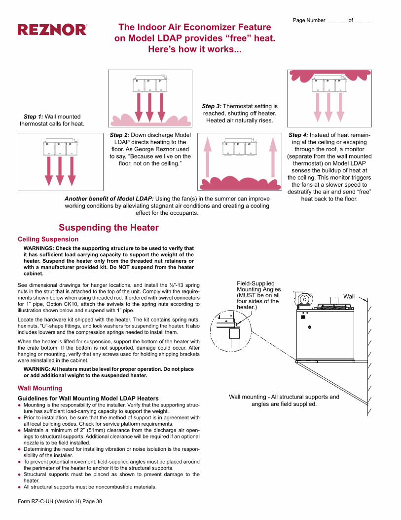
The Indoor Air Economizer Feature on Model LDAP provides “free” heat. Here’s how it works... Step 1: Wall mounted thermostat calls for heat. Step 2: Down discharge Model LDAP directs heating to the floor. As George Reznor used to say, “Because we live on the floor, not on the ceiling.” Step 3: Thermostat setting is reached, shutting off heater. Heated air naturally rises. Step 4: Instead of heat remain- ing at the ceiling or escaping through the roof, a monitor (separate from the wall mounted thermostat) on Model LDAP senses the buildup of heat at the ceiling. This monitor triggers the fans at a slower speed to destratify the air and send “free” heat back to the floor. Another benefit of Model LDAP: Using the fan(s) in the summer can improve working conditions by alleviating stagnant air conditions and creating a cooling effect for the occupants. Suspending the Heater Ceiling Suspension WARNINGS: Check the supporting structure to be used to verify that it has sufficient load carrying capacity to support the weight of the heater. Suspend the heater only from the threaded nut retainers or with a manufacturer provided kit. Do NOT suspend from the heater cabinet. See dimensional drawings for hanger locations, and install the ½”-13 spring nuts in the strut that is attached to the top of the unit. Comply with the require- ments shown below when using threaded rod. If ordered with swivel connectors for 1” pipe, Option CK10, attach the swivels to the spring nuts according to illustration shown below and suspend with 1” pipe. Locate the hardware kit shipped with the heater. The kit contains spring nuts, hex nuts, “U”-shape fittings, and lock washers for suspending the heater. It also includes louvers and the compression springs needed to install them. When the heater is lifted for suspension, support the bottom of the heater with the crate bottom. If the bottom is not supported, damage could occur. After hanging or mounting, verify that any screws used for holding shipping brackets were reinstalled in the cabinet. WARNING: All heaters must be level for proper operation. Do not place or add additional weight to the suspended heater. Wall Mounting Guidelines for Wall Mounting Model LDAP Heaters ● Mounting is the responsibility of the installer. Verify that the supporting struc- ture has sufficient load-carrying capacity to support the weight. ● Prior to installation, be sure that the method of support is in agreement with all local building codes. Check for service platform requirements. ● Maintain a minimum of 2” (51mm) clearance from the discharge air open- ings to structural supports. Additional clearance will be required if an optional nozzle is to be field installed. ● Determining the need for installing vibration or noise isolation is the respon- sibility of the installer. ● To prevent potential movement, field-supplied angles must be placed around the perimeter of the heater to anchor it to the structural supports. ● Structural supports must be placed as shown to prevent damage to the heater. ● All structural supports must be noncombustible materials. Wall mounting - All structural supports and angles are field supplied. Form RZ-C-UH (Version H) Page 38 Page Number _______ of ______
Transcript of Page Numer of The Indoor Air Economizer Feature on … · The Indoor Air Economizer Feature on...
TheIndoorAirEconomizerFeature onModelLDAPprovides“free”heat.
Here’s how it works...
Step 1: Wall mounted thermostat calls for heat.
Step 2: Down discharge Model LDAP directs heating to the
floor. As George Reznor used to say, “Because we live on the
floor, not on the ceiling.”
Step 3: Thermostat setting is reached, shutting off heater. Heated air naturally rises.
Step 4: Instead of heat remain-ing at the ceiling or escaping through the roof, a monitor
(separate from the wall mounted thermostat) on Model LDAP senses the buildup of heat at
the ceiling. This monitor triggers the fans at a slower speed to
destratify the air and send “free” heat back to the floor.Another benefit of Model LDAP: Using the fan(s) in the summer can improve
working conditions by alleviating stagnant air conditions and creating a cooling effect for the occupants.
������������������������������� ���������������������������������
���
Suspending the HeaterCeiling SuspensionWARNINGS:Checkthesupportingstructuretobeusedtoverifythatithassufficientloadcarryingcapacitytosupporttheweightoftheheater.Suspendtheheateronlyfromthethreadednutretainersorwithamanufacturerprovidedkit.DoNOTsuspendfromtheheatercabinet.
See dimensional drawings for hanger locations, and install the ½”-13 spring nuts in the strut that is attached to the top of the unit. Comply with the require-ments shown below when using threaded rod. If ordered with swivel connectors for 1” pipe, Option CK10, attach the swivels to the spring nuts according to illustration shown below and suspend with 1” pipe.
Locate the hardware kit shipped with the heater. The kit contains spring nuts, hex nuts, “U”-shape fittings, and lock washers for suspending the heater. It also includes louvers and the compression springs needed to install them.
When the heater is lifted for suspension, support the bottom of the heater with the crate bottom. If the bottom is not supported, damage could occur. After hanging or mounting, verify that any screws used for holding shipping brackets were reinstalled in the cabinet.WARNING:Allheatersmustbelevelforproperoperation.Donotplaceor add additional weight to the suspended heater.
wall MountingGuidelines for wall Mounting Model LDAP Heaters
● Mounting is the responsibility of the installer. Verify that the supporting struc-ture has sufficient load-carrying capacity to support the weight.
● Prior to installation, be sure that the method of support is in agreement with all local building codes. Check for service platform requirements.
● Maintain a minimum of 2” (51mm) clearance from the discharge air open-ings to structural supports. Additional clearance will be required if an optional nozzle is to be field installed.
● Determining the need for installing vibration or noise isolation is the respon-sibility of the installer.
● To prevent potential movement, field-supplied angles must be placed around the perimeter of the heater to anchor it to the structural supports.
● Structural supports must be placed as shown to prevent damage to the heater.
● All structural supports must be noncombustible materials.
Wall mounting - All structural supports and angles are field supplied.
Form RZ-C-UH (Version H) Page 38
Page Number _______ of ______
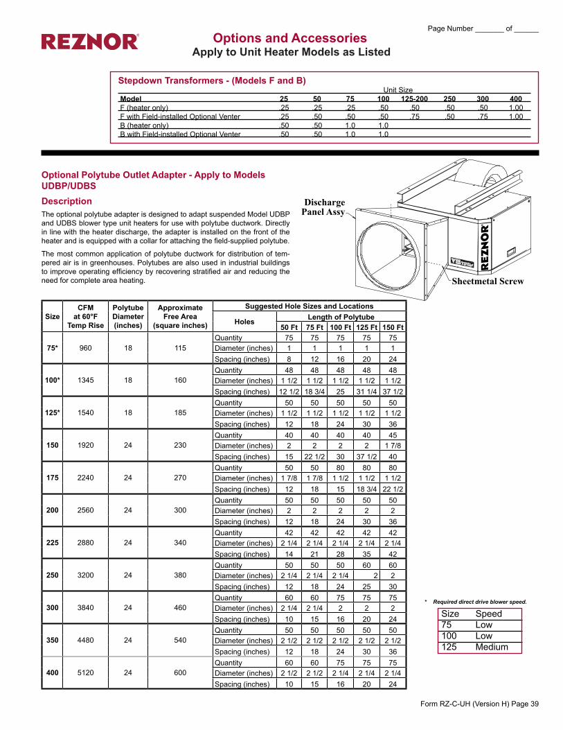
OptionalPolytubeOutletAdapter-ApplytoModelsUDBP/UDBSDescriptionThe optional polytube adapter is designed to adapt suspended Model UDBP and UDBS blower type unit heaters for use with polytube ductwork. Directly in line with the heater discharge, the adapter is installed on the front of the heater and is equipped with a collar for attaching the field-supplied polytube.
The most common application of polytube ductwork for distribution of tem-pered air is in greenhouses. Polytubes are also used in industrial buildings to improve operating efficiency by recovering stratified air and reducing the need for complete area heating. ����������������
������������������
�
�
* Required direct drive blower speed.
Size Speed75 Low100 Low125 Medium
SizeCFM
at 60°F Temp Rise
Polytube Diameter (inches)
Approximate Free Area
(squareinches)
SuggestedHoleSizesandLocations
Holes LengthofPolytube50 Ft 75 Ft 100 Ft 125 Ft 150 Ft
75* 960 18 115Quantity 75 75 75 75 75Diameter (inches) 1 1 1 1 1Spacing (inches) 8 12 16 20 24
100* 1345 18 160Quantity 48 48 48 48 48Diameter (inches) 1 1/2 1 1/2 1 1/2 1 1/2 1 1/2Spacing (inches) 12 1/2 18 3/4 25 31 1/4 37 1/2
125* 1540 18 185Quantity 50 50 50 50 50Diameter (inches) 1 1/2 1 1/2 1 1/2 1 1/2 1 1/2Spacing (inches) 12 18 24 30 36
150 1920 24 230Quantity 40 40 40 40 45Diameter (inches) 2 2 2 2 1 7/8Spacing (inches) 15 22 1/2 30 37 1/2 40
175 2240 24 270Quantity 50 50 80 80 80Diameter (inches) 1 7/8 1 7/8 1 1/2 1 1/2 1 1/2Spacing (inches) 12 18 15 18 3/4 22 1/2
200 2560 24 300Quantity 50 50 50 50 50Diameter (inches) 2 2 2 2 2Spacing (inches) 12 18 24 30 36
225 2880 24 340Quantity 42 42 42 42 42Diameter (inches) 2 1/4 2 1/4 2 1/4 2 1/4 2 1/4Spacing (inches) 14 21 28 35 42
250 3200 24 380Quantity 50 50 50 60 60Diameter (inches) 2 1/4 2 1/4 2 1/4 2 2Spacing (inches) 12 18 24 25 30
300 3840 24 460Quantity 60 60 75 75 75Diameter (inches) 2 1/4 2 1/4 2 2 2Spacing (inches) 10 15 16 20 24
350 4480 24 540Quantity 50 50 50 50 50Diameter (inches) 2 1/2 2 1/2 2 1/2 2 1/2 2 1/2Spacing (inches) 12 18 24 30 36
400 5120 24 600Quantity 60 60 75 75 75Diameter (inches) 2 1/2 2 1/2 2 1/4 2 1/4 2 1/4Spacing (inches) 10 15 16 20 24
OptionsandAccessoriesApplytoUnitHeaterModelsasListed
StepdownTransformers-(ModelsFandB) Unit SizeModel 25 50 75 100 125-200 250 300 400F (heater only) .25 .25 .25 .50 .50 .50 .50 1.00F with Field-installed Optional Venter .25 .50 .50 .50 .75 .50 .75 1.00B (heater only) .50 .50 1.0 1.0B with Field-installed Optional Venter .50 .50 1.0 1.0
Form RZ-C-UH (Version H) Page 39
Page Number _______ of ______

OptionalPolytubeOutletAdapter-ApplytoModelBDescriptionThe optional outlet nozzle is designed to allow the attachment of polytube-type air distribu-tion for use in greenhouse and industrial buildings. Outlet on suspended heater may be either above, below, or directly in line with the heater discharge. A kit is available to floor mount the heater with outlet below the heater discharge (see illustration). Model B stan-dard blower and drive are designed to handle rated CFM at .25 w.c. ESP, and will inflate a 24" tube up to 150 ft. long. See table for proper free area, minimum number of holes and sizes. Units may be used for greenhouse heating and ventilating or in industrial applica-tions requiring high mounting heights or spot heating by means of polytube distribution.
The total open or free area of the polytube is important. Polytube suppliers have a great deal of flexibility in placement and sizing of holes. Too small of a free area will cause over-heating. Excessive open area may not permit the tube to inflate. See the table below for a guide in hole size and location. Spacing and hole size may be varied, but free area must not be less than shown for the heater being installed.
Greenhouse Application - For greenhouse use, the number of units required is generally based on an airflow volume of 1-1/2 to 2 CFM per square foot of house floor area. Depend-ing on the heat loss requirements of the house type, location, and desired temperature above ambient, the ventilation requirements determine the number of distribution systems required and the heat loss determines the BTUH heater size required. As a general rule, a single system will serve a maximum house width of 30 ft. and a length of 150 ft.
Conversion Table (Diameter to Area)
Diameter Areaof the of theHole Hole
(inches) (square inches)2-1/2 4.912-1/4 3.982 3.141-7/8 2.761-1/2 1.761 0.785
Photograph shows polytube outlet. The outlet nozzle requires field assembly and installation on the standard unit in place of the top front panel and louvers. The heater manufacturer does not supply tub-ing. Tubing can be ordered from a local greenhouse supply distributor. Two such suppliers are FOF Products, Inc. P. O. Box E, 1505 Racine Street, Delevan, WI 53115 and ACME Engineering Co., P.O. Box 978, Muskogee, OK 74402.
CAUTION: To prevent overheating of the blower unit heater and to ensure correct air distribution, the minimum hole area must be provided as shown in the table for each size. If more holes are used, do not exceed 1.25 times the minimum area shown to en-sure proper tube inflation.
OptionsandAccessories(cont'd)ApplytoUnitHeaterModelsasListed
SizeCFM at
.25” ESP
Polytube Diameter (inches)
Minimum Free Area (sq.in.)
SuggestedHoleSizesandLocations
Holes LengthofPolytube50 Ft 75 Ft 100 Ft 125 Ft 150 Ft
75 925 18 110Number 37pairs 75 pairs 75 pairs - - - -Diameter 1-1/2” 1” 1” - - - -Spacing 16” 12” 16” - - - -
100 1235 18 145Number 50 pairs 50 pairs 100 pairs 94 pairs - -Diameter 1-1/2” 1-1/2” 1” 1” - -Spacing 12” 18” 12” 16” - -
125 1540 18 185Number 40 pairs 60 pairs 60 pairs 125 pairs - -Diameter 1-7/8” 1-1/2” 1-1/2” 1” - -Spacing 15” 15” 20” 12” - -
130 1600 24 190Number 40 pairs 60 pairs 60 pairs 125 pairs - -Diameter 1-7/8” 1-1/2” 1-1/2” 1” - -Spacing 15” 15” 20” 12” - -
165 2035 24 240Number 50 pairs 50 pairs 75 pairs 75 pairs 75 pairsDiameter 1-7/8” 1-7/8” 1-1/2” 1-1/2” 1-1/2”Spacing 12” 18” 16” 20” 24”
200 2465 24 300Number 42 pairs 42 pairs 60 pairs 60 pairs 100 pairsDiameter 2-1/4” 2-1/4” 1-7/8” 1-7/8” 1-1/2”Spacing 14” 21” 20” 25” 18”
250 3085 24 360Number 40 pairs 60 pairs 60 pairs 60 pairs 60 pairsDiameter 2-1/2” 2” 2” 2” 2”Spacing 15” 15” 20” 25” 30”
300 3700 24 425Number 75 pairs 75 pairs 75 pairs 75 pairs 75 pairsDiameter 2” 2” 2” 2” 2”Spacing 9” 12” 16” 20” 24”
400 4935 24 550Number 60 pairs 60 pairs 60 pairs 100 pairs 100 pairsDiameter 2-1/2” 2-1/2” 2-1/2” 1-7/8” 1-7/8”Spacing 10” 15” 20” 15” 18”
Form RZ-C-UH (Version H) Page 40
Page Number _______ of ______
OptionalDownturnNozzles-ApplytoModelsUDAP,UDAS,UDBP,UDBS,UEAS,FandB
Optional Downturn
Nozzle with 25°-65° Range of Air Deflec-
tion
Optional Down-turn Nozzle with 50°-90° Range of Air Deflection
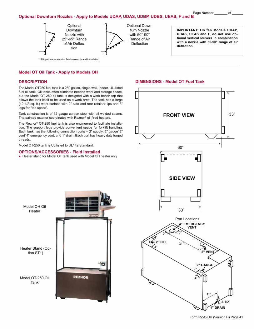
ModelOTOilTank-ApplytoModelsOH
DESCRIPTIONThe Model OT250 fuel tank is a 250 gallon, single-wall, indoor, UL-listed fuel oil tank. Oil tanks often eliminate needed work and storage space, but the Model OT-250 oil tank is designed with a work bench top that allows the tank itself to be used as a work area. The tank has a large (12-1/2 sq. ft.) work surface with 2" side and rear retainer lips and 3" legs for "toe space".
Tank construction is of 12 gauge carbon steel with all welded seams. The painted exterior coordinates with Reznor® oil-fired heaters.
The Reznor® OT-250 fuel tank is also engineered to facilitate installa-tion. The support legs provide convenient space for forklift handling. Each tank has the following connection ports -- 2" supply; 2" gauge' 2" vent' 4" emergency vent; and 1" drain. Each port has heavy duty forged threads.
Model OT-250 tank is UL listed to UL142 Standard.
OPTIONS/ACCESSORIES - Field Installed ● Heater stand for Model OT tank used with Model OH heater only
��
��
����
���� ��
���
���
������
��������
��������
�������
�������
���������� �����
Model OH Oil Heater
Heater Stand (Op-tion ST1)
Model OT-250 Oil Tank
DIMENSIONS - Model OT Fuel Tank
Port Locations
• Shipped separately for field assembly and installation
���
�������������
���
���������
IMPORTANT: On fan Models UDAP, UDAS, UEAS and F, do not use op-tional vertical louvers in combinationwith a nozzle with 50-90° range of air deflection.
,
Form RZ-C-UH (Version H) Page 41
Page Number _______ of ______

��������������������������������������� ���������������������������
�����������������
ModelLDAPDischargeAirOptions
��������������������������������� ������������
��������������������������������� ������������
LOUVERS
Option CD58, 60° Discharge Nozzle
After the unit is suspended/mounted, install the air directional louvers or optional nozzle. If an optional nozzle is being installed, follow the instructions included with the nozzle. If a nozzle is not being used, install the louvers in the discharge opening(s).
Louvers and springs are in the hardware kit shipped with the heater.
Before actually installing the louvers, note the louver curve and determine how the louvers should be positioned to provide the optimal throw pattern. Opening is square so louvers may be installed in any direction. Louvers may be installed with the curve all the same direction (either way) or the right half one way and left the other as illustrated above.
1) With the wider section of the louver facing out of the heater, place one of the compression springs over the tab on the notched end of a louver. The end of the louver with the spring will fit in any direction in the square opening. How the louver turns depends on which end of the louver is inserted first.
2) Depending on the throw pattern selected, push the louver tab with the spring into a hole in the discharge opening and insert the louver tab on the other end into the corresponding hole on the opposite side.
3) Airflow direction depends on how the louvers are installed (see illustration above).
Option CD32 consists of additional louvers that are installed perpendicular to the standard individually adjust-able louvers. By installing the optional perpendicular louvers, the two sets of louvers can be adjusted to direct airflow in any of the four directions, enabling the installer to select and increase or decrease the coverage area.
Option CD57 is a 30° angle discharge nozzle. Option CD58 is a 60° angle discharge nozzle. Option CD59 is a 30° angle discharge nozzle with 4-way louvers. A nozzle may be installed at each discharge air opening in any direction. NOTE: Do not install 4-way louvers with a 60° nozzle.
Nozzles should be attached after the unit is suspended. Follow the installation instructions in the nozzle pack-age.
Standard louvers are installed in the nozzle opening as shown in the photo on the left.
INSTALLING LOUVERS
LOUVER INSTALLATION INSTRUCTIONS
FOUR-wAY DISCHARGE LOUVERS(OptionCD32)
MULTIPLE POSITION DISCHARGE NOzzLE
Airflow direction depends on how the louvers are installed
Option CD57,30° Nozzle
Option CD58,60° Nozzle
Option CD59, 30° Nozzlewith 4-Way Louvers
24-3/8”(618mm)
14-1/8”(360mm)
Form RZ-C-UH (Version H) Page 42
Page Number _______ of ______

The manufacturer of Reznor heating equipment, for years, has pioneered in separated combustion system technology, eliminating “open flame” combustion problems. This has resulted in a complete line of Reznor products using the separated combustion principle-
● air for combustion is mechanically induced from outside the building, preventing dirt, lint, dust or other contaminants in the indoor atmosphere from entering the burner and combustion zone of the furnace,
● the air flow is metered to provide optimum and efficient combustion that is unaffected by negative building pressure or wind,
● after combustion, the air is exhausted back to the outdoor atmosphere.
Reznor separated combustion products provide all of the benefits while requiring only one building penetration. See the venting illustrations below.
Use only approved vent terminals. No other venting arrangements are approved or certified for use with Models UDAS, UDBS or UEAS heaters. Either the horizontal vent/combustion air terminal kit (Option CC6 or Option CC14) or the vertical vent/combustion air terminal kit (Option CC2) is required.
Refer to Venting Installation Manual Form I-UD-V-SC for Models UDAS and UDBS; Form I-UEAS for Model UEAS. Or contact your Reznor Representative at 800-695-1901 for more detailed information.
HorizontalVentingofSeparatedCombustionUnit through wall
● See the illustration to the right for a typical installation of a single horizontal vent terminal and concentric adapter. When Option CC6 is ordered, one horizontal vent terminal/combustion air inlet assembly is provided.
NOTE: Illustration for typical installation example only. Vent terminals may vary based on heater size and model.
VerticalVentingofSeparatedCombustionUnit through Roof
● See the illustration to the right for a typical installation of one vertical vent terminal and concentric adapter. If vertical vent (Option CC2) is selected, a vertical vent terminal/com-bustion-air inlet assembly is provided.
NOTE: Illustration for typical installation example only. Vent terminals may vary based on heater size and model.
Option CC14Vent/Combustion
Air Terminal
WallPainted Concentric Adapter Boxextends onl 3” (76mm) from the wall.
Combustion AirPipe to the Heater
ConcentricPipes
Exhaust Air VentPipe from the Heater
Residential Garage - Horizontal Venting of SeparatedCombustionUnitthroughWall(Models UDAS and UDBS Only)
Option CC14, the Compact, Aesthetic, Concentric Vent/Com-bustion Air, Horizontal Vent Kit is for use with Model UDAS and UDBS in sizes 30, 45, 60, and 75.
The most common use for these vent kit is for Model UDAS for residential garage installations. This option allows a hom-eowner to vent out a side wall and avoid the unsightly 18" to 36" exhaust vent. This attractive vent kit preserves the home's exterior appearance.
For more information, contact your Reznor Representative at 800-695-1901, or see the instruction manual Form I-UDAS/UDBS-ASC.NOTE: Siding trim is field-supplied by contractor to match home appear-ance.
ReznorSeparatedCombustionSystemsFollowingisanoveralldescriptionofSeparatedCombustionSystemsasitrelatesto
ModelsUDASandUDBS.Formorespecificseparatedcombustionventinginformation,especiallyasitrelatestoModelUEAS,pleaseseetheappropriateinstallationmanual.
For installations where dirt, dust, and other air borne contamination is present in the indoor environment, it is recommended to use separated combustion units (UDAS, UDBS). These models use air from outside the space for combustion. This will help reduce the build up of contami-nates on the burner which would af-fect the combustion process. Refer to the installation manuals for recom-mended frequency of maintenance and cleaning.
Form RZ-C-UH (Version H) Page 43
Page Number _______ of ______


![1 Indoor Localization for IoT Using Adaptive Feature Selection: A … · 2019-05-06 · arXiv:1905.01000v1 [eess.SP] 3 May 2019 1 Indoor Localization for IoT Using Adaptive Feature](https://static.fdocuments.in/doc/165x107/5f456d9940a14b3d4049947d/1-indoor-localization-for-iot-using-adaptive-feature-selection-a-2019-05-06-arxiv190501000v1.jpg)