Indoor Vertical Self-Contained Air Conditioner YSWU … · 4 YORK INTERNATIONAL FORM 145.05-EG1...
48
FORM 145.05-EG1 (1004) VERSECON ™ Indoor Vertical Self-Contained Air Conditioner YSWU 10–105 Ton Water-Cooled
Transcript of Indoor Vertical Self-Contained Air Conditioner YSWU … · 4 YORK INTERNATIONAL FORM 145.05-EG1...

FORM 145.05-EG1 (1004)
VERSECON™
Indoor Vertical Self-Contained Air Conditioner
YSWU 10–105 Ton Water-Cooled

Features and Benefits . . . . . . . . . . . . . . . . . . . . . . . . . . . . . . . . . . . . . . . . . . . . . . . . . . . . . 1
Design Features . . . . . . . . . . . . . . . . . . . . . . . . . . . . . . . . . . . . . . . . . . . . . . . . . . . . . . . . . . 6
Economizer Comparison . . . . . . . . . . . . . . . . . . . . . . . . . . . . . . . . . . . . . . . . . . . . . . . . . . . 7
Operating Limits . . . . . . . . . . . . . . . . . . . . . . . . . . . . . . . . . . . . . . . . . . . . . . . . . . . . . . . . . 8
Selection Procedure . . . . . . . . . . . . . . . . . . . . . . . . . . . . . . . . . . . . . . . . . . . . . . . . . . . . . . . 9
Model Nomenclature and Data Table . . . . . . . . . . . . . . . . . . . . . . . . . . . . . . . . . . . . . . . . 11
Cooling Capacity
DX . . . . . . . . . . . . . . . . . . . . . . . . . . . . . . . . . . . . . . . . . . . . . . . . . . . . . . . . . . . . . . . . 13
Waterside Economizer . . . . . . . . . . . . . . . . . . . . . . . . . . . . . . . . . . . . . . . . . . . . . . . . . 20
Heating Capacity
Hot Water . . . . . . . . . . . . . . . . . . . . . . . . . . . . . . . . . . . . . . . . . . . . . . . . . . . . . . . . . . . 23
Steam . . . . . . . . . . . . . . . . . . . . . . . . . . . . . . . . . . . . . . . . . . . . . . . . . . . . . . . . . . . . . 24
Dimensional Data
Unit - YSWU 012, 016, 021, 025 and 032 . . . . . . . . . . . . . . . . . . . . . . . . . . . . . . . . . . . 25
Unit - YSWU 039, 048, 050, 055, 060, 063, 072, 073, 079 and 090 . . . . . . . . . . . . . . . . 26
Recommended Service Clearances . . . . . . . . . . . . . . . . . . . . . . . . . . . . . . . . . . . . . . . . . . 27
Air Pressure Drop . . . . . . . . . . . . . . . . . . . . . . . . . . . . . . . . . . . . . . . . . . . . . . . . . . . . . . . . 28
Fan Curves . . . . . . . . . . . . . . . . . . . . . . . . . . . . . . . . . . . . . . . . . . . . . . . . . . . . . . . . . . . . . 29
Water Pressure Drop
Condenser . . . . . . . . . . . . . . . . . . . . . . . . . . . . . . . . . . . . . . . . . . . . . . . . . . . . . . . . . . 33
Waterside Economizer . . . . . . . . . . . . . . . . . . . . . . . . . . . . . . . . . . . . . . . . . . . . FUTURE
Head Pressure Control Valve. . . . . . . . . . . . . . . . . . . . . . . . . . . . . . . . . . . . . . . . FUTURE
Electrical Data. . . . . . . . . . . . . . . . . . . . . . . . . . . . . . . . . . . . . . . . . . . . . . . . . . . . . . . . . . . 36
Weights . . . . . . . . . . . . . . . . . . . . . . . . . . . . . . . . . . . . . . . . . . . . . . . . . . . . . . . . . . . . . . . . 37
Specifications
Mechanical . . . . . . . . . . . . . . . . . . . . . . . . . . . . . . . . . . . . . . . . . . . . . . . . . . . . . . . . . . 39
Sequence Of Operation . . . . . . . . . . . . . . . . . . . . . . . . . . . . . . . . . . . . . . . . . . . . . . . . 44
Control Algorithms. . . . . . . . . . . . . . . . . . . . . . . . . . . . . . . . . . . . . . . . . . . . . . . . . . . . . 45
Building Automation System/Energy Management
BACnet™ . . . . . . . . . . . . . . . . . . . . . . . . . . . . . . . . . . . . . . . . . . . . . . . . . . . . . . . 46
Hard Wire . . . . . . . . . . . . . . . . . . . . . . . . . . . . . . . . . . . . . . . . . . . . . . . . . . . . . . . 46
2 YORK INTERNATIONAL
FORM 145.05-EG1 (0804)
Table of Contents
3YORK INTERNATIONAL
FORM 145.05-EG1 (0804)
Features and Benefits
Versecon offers a simple system design,
increases system redundancy by providing
individual air conditioning systems per
f loor, l owers maintenance costs, and
eases operation and maintenance.
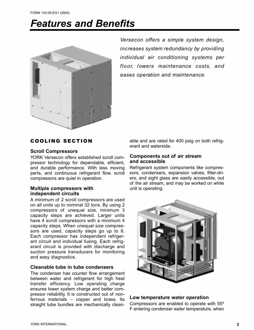
COOLING SECTION
Scroll Compressors
YORK Versecon offers established scroll com-pressor technology for dependable, efficient,and durable performance. With less movingparts, and continuous refrigerant flow, scrollcompressors are quiet in operation.
Multiple compressors with independent circuits
A minimum of 2 scroll compressors are usedon all units up to nominal 32 tons. By using 2compressors of unequal size, minimum 3capacity steps are achieved. Larger unitshave 4 scroll compressors with a minimum 4capacity steps. When unequal size compres-sors are used, capacity steps go up to 6.Each compressor has independent refriger-ant circuit and individual fusing. Each refrig-erant circuit is provided with discharge andsuction pressure transducers for monitoringand easy diagnostics.
Cleanable tube in tube condensers
The condenser has counter flow arrangementbetween water and refrigerant for high heattransfer efficiency. Low operating chargeensures lower system charge and better com-pressor reliability. It is constructed out of non-ferrous materials – copper and brass. Itsstraight tube bundles are mechanically clean-
able and are rated for 400 psig on both refrig-erant and waterside.
Components out of air stream and accessible
Refrigerant system components like compres-sors, condensers, expansion valves, filter-dri-ers, and sight glass are easily accessible, outof the air stream, and may be worked on whileunit is operating.
Low temperature water operation
Compressors are enabled to operate with 55ºF entering condenser water temperature, when

4 YORK INTERNATIONAL
FORM 145.05-EG1 (0804)
there is no waterside economizer, and at 50º Fwith waterside economizer. At these water tem-peratures, the compressor energy consump-tion is typically less than 0.5 kW per ton.Compressor operation at lower condenserwater temperatures is available with condenserwater flow control.
Evaporator coil
This coil, 4 row or 6 row, is row split, with eachrefrigerant circuit covering entire coil face in 2-compressor units. In 4 compressor units, thecoil is row split and has intertwined circuiting toactivate entire coil face when any compressoris started.
Waterside economizer – Optional
4 row waterside economizer coil is offered aschemically cleanable or mechanically cleanable.In either case, the coil is rated for 400 psigwaterside pressure. Waterside economizeroption also includes complete water piping, sen-sors, and 2 two-way motorized valves for controlof the economizer cycle. When condenserwater is colder than the mixed air entering theunit, waterside economizer is activated, allowingthe condenser water through the watersideeconomizer coil. If additional cooling is requiredto meet the load, condenser water leaving theeconomizer coil enters the condenser, and com-pressors are turned on as needed.
FAN SECTION
Plenum fan – quiet, efficient
The YORK Versecon uses an efficient and quietairfoil blade backward curve plenum fan, with aminimum of Class II construction. The fan sec-tion acts as a plenum, keeping discharge veloc-ities and noise lower, and efficiency high.Bearing lubrication lines are brought closer tothe front of the unit for easy maintenance.
Vibration isolation
Fan is mounted on vibration isolation springsand connected on the inlet side with a canvasflexible connection, minimizing vibration andnoise transmission.
Double wall construction
Unit cabinet in the air stream has double wallconstruction with 22 gage perforated liner to
absorb maximum amount of noise and to holdthe insulation permanently in place without useof studs or glue.
Variable Air volume with unit mountedand tested VFD – Optional
Variable air volume units include a unit mount-ed and tested Variable Frequency Drive on all460 volt motors and up to 25 HP motors on 208or 230 volt units. Unit controller adjusts theVFD speed to maintain static pressure assensed by a unit mounted differential air pres-sure transducer. The pressure transducersenses air pressure at an appropriate locationin the supply ductwork through a pressure tubesupplied and installed by others. All VAV unitsare supplied with a Duct High Limit pressureswitch to stop the supply fan if the supply airpressure exceeds the set point.
CONDESNSER WATER PIPING DIAGRAMmechanical cooling mode only
CONDESNSER WATER PIPING DIAGRAMeconomizer with or without mechanical cooling mode
Economizer Coil
Evaporator Coil
Economizer Coil
Evaporator Coil
Condenser Water Supply(CWS)
Condenser Water Return(CWR)
Bypass Valve & Actuator
Economizer Valve &Actuator
Water Cooled Condenser
Condenser Water Supply(CWS)
Condenser Water &Return (CWR)
Bypass Valve & Actuator
Economizer Valve &Actuator
Water Cooled Condenser
5YORK INTERNATIONAL
FORM 145.05-EG1 (0804)
HEATING – OPTIONAL
Hot water
Factory installed modulating hot water heat isoffered with the hot water coil upstream of theevaporator coil. It is complete with hot waterpiping and a two-way motorized hot watervalve. The unit controller modulates motorizedhot water valve.
Steam
Steam coil is installed upstream of the evapora-tor coil. Unit controller provides a signal for con-trol of the steam valve, provided and installed byothers. All other steam accessories includingsteam valve, valve actuator, and steam trap etc.are provided and installed by others.
Electric
Factory installed electric heat is at the unit out-let, and requires discharge air plenum. Unitcontroller operates the 2-stage electric heat.
CONTROLS AND BASCOMMUNICATIONS
YORK Versecon comes complete with a con-troller and a variety of sensors throughout theunit for reliable unit operation. A return air tem-perature sensor, supplied with the unit, isinstalled by others to read return air tempera-ture before it mixes with the outdoor air. UnitMounted keypad and display, accessible with-out opening any panels, is provided as userinterface to monitor unit operation and changeset points. York Versecon may be adapted tooperate with any building automation systemthat is BACnet (MSTP) compatible. Other pro-tocol options are also available.
INDOOR AIR QUALITY
Condensate Drain Pan
A stainless steel drain pan sloped in all direc-tions collects condensate from coils and col-lects it at a single location that is the lowest inthe drain pan. This ensures that there is nostanding water at any time in the drain pan,avoiding microbial growth in the drain pan.
Solid Liners – Optional
Galvanized solid liners may be ordered in theair stream in lieu of the standard perforated lin-ers. This allows wash-down of the unit air path.
High Efficiency Filtration – Optional
30% Efficiency filters are standard 4-inch highefficiency filters (up to 90%) with 30% efficien-cy pre-filters are available.
ACCESSORIES
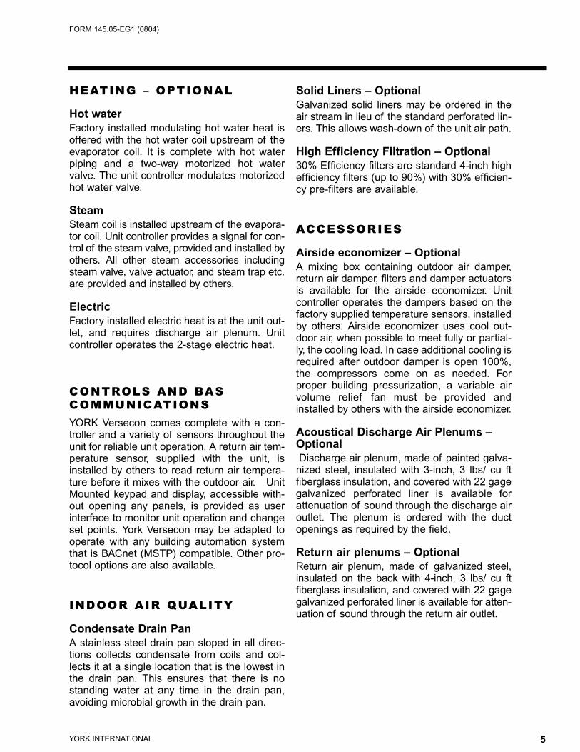
Airside economizer – Optional
A mixing box containing outdoor air damper,return air damper, filters and damper actuatorsis available for the airside economizer. Unitcontroller operates the dampers based on thefactory supplied temperature sensors, installedby others. Airside economizer uses cool out-door air, when possible to meet fully or partial-ly, the cooling load. In case additional cooling isrequired after outdoor damper is open 100%,the compressors come on as needed. Forproper building pressurization, a variable airvolume relief fan must be provided andinstalled by others with the airside economizer.
Acoustical Discharge Air Plenums –Optional
Discharge air plenum, made of painted galva-nized steel, insulated with 3-inch, 3 lbs/ cu ftfiberglass insulation, and covered with 22 gagegalvanized perforated liner is available forattenuation of sound through the discharge airoutlet. The plenum is ordered with the ductopenings as required by the field.
Return air plenums – Optional
Return air plenum, made of galvanized steel,insulated on the back with 4-inch, 3 lbs/ cu ftfiberglass insulation, and covered with 22 gagegalvanized perforated liner is available for atten-uation of sound through the return air outlet.
6 YORK INTERNATIONAL
FORM 145.05-EG1 (0804)
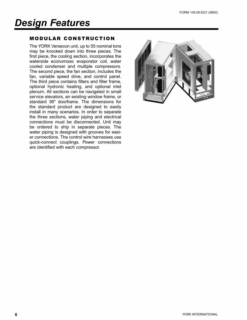
MODULAR CONSTRUCTION
The YORK Versecon unit, up to 55 nominal tonsmay be knocked down into three pieces. Thefirst piece, the cooling section, incorporates thewaterside economizer, evaporator coil, watercooled condenser and multiple compressors.The second piece, the fan section, includes thefan, variable speed drive, and control panel.The third piece contains filters and filter frame,optional hydronic heating, and optional inletplenum. All sections can be navigated in smallservice elevators, an existing window frame, orstandard 36" doorframe. The dimensions forthe standard product are designed to easilyinstall in many scenarios. In order to separatethe three sections, water piping and electricalconnections must be disconnected. Unit maybe ordered to ship in separate pieces. Thewater piping is designed with grooves for easi-er connections. The control wire harnesses usequick-connect couplings. Power connectionsare identified with each compressor.
Design Features
7YORK INTERNATIONAL
FORM 145.05-EG1 (0804)
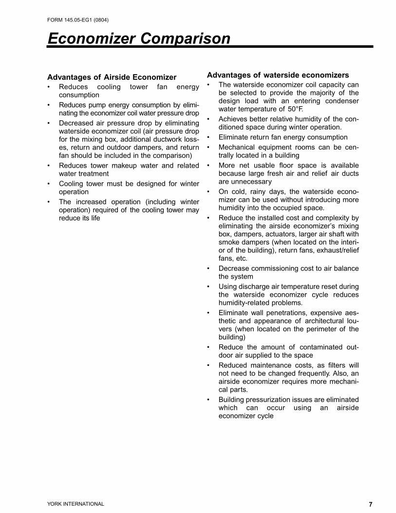
Advantages of Airside Economizer
• Reduces cooling tower fan energy consumption
• Reduces pump energy consumption by elimi-nating the economizer coil water pressure drop
• Decreased air pressure drop by eliminatingwaterside economizer coil (air pressure dropfor the mixing box, additional ductwork loss-es, return and outdoor dampers, and returnfan should be included in the comparison)
• Reduces tower makeup water and relatedwater treatment
• Cooling tower must be designed for winteroperation
• The increased operation (including winteroperation) required of the cooling tower mayreduce its life
Advantages of waterside economizers
• The waterside economizer coil capacity canbe selected to provide the majority of thedesign load with an entering condenserwater temperature of 50°F.
• Achieves better relative humidity of the con-ditioned space during winter operation.
• Eliminate return fan energy consumption• Mechanical equipment rooms can be cen-
trally located in a building• More net usable floor space is available
because large fresh air and relief air ducts are unnecessary
• On cold, rainy days, the waterside econo-mizer can be used without introducing morehumidity into the occupied space.
• Reduce the installed cost and complexity byeliminating the airside economizer’s mixingbox, dampers, actuators, larger air shaft withsmoke dampers (when located on the interi-or of the building), return fans, exhaust/relieffans, etc.
• Decrease commissioning cost to air balancethe system
• Using discharge air temperature reset duringthe waterside economizer cycle reduceshumidity-related problems.
• Eliminate wall penetrations, expensive aes-thetic and appearance of architectural lou-vers (when located on the perimeter of thebuilding)
• Reduce the amount of contaminated out-door air supplied to the space
• Reduced maintenance costs, as filters willnot need to be changed frequently. Also, anairside economizer requires more mechani-cal parts.
• Building pressurization issues are eliminatedwhich can occur using an airside economizer cycle
Economizer Comparison

8 YORK INTERNATIONAL
FORM 145.05-EG1 (0804)
Airflow
The minimum VAV design airflow limits arealso listed in the data table on pages 11 and12. This airflow corresponds to 400 FPM veloc-ity over DX coil. It is highly recommended tokeep the face velocity above 200 FPM. Thisminimum face velocity prevents heat transferand refrigerant control problems. At the mini-mum design airflow, therefore, 50% turndownis available. At the maximum airflow for theunit, 33% turndown is available. Once the unitsare installed and the fit out work is complete,the entire air system needs to be air balanced.As part of this procedure, it is very critical thatthe total minimum airflow for the VAV boxes isset to be the same as or greater than the abso-lute minimum airflow for the York Verseconunit. This should cover all VAV box positionscenarios, including if only one zone needscooling. If the VAV box and unit minimum air-flow are not coordinated, the low face veloci-ties will cause nuisance alarms in theself-contained unit.
Condenser Water Flow
Typical design condenser water flow for awater-cooled unit is 3.0 gpm/ton. This corre-sponds to a 10°F difference between the enter-ing and leaving condenser water temperatures.The Versecon unit is designed for a minimumwater flow of 2.0 gpm/ton. This corresponds toa 15°F condenser water temperature change.The benefit of using a lower gpm/ton is the costsavings for the smaller diameter pipe, smallerpump and pumping costs. The downside tousing a lower water flow is it will increase theleaving condenser water temperature. With theincrease in water temperature, there is anincrease in the condensing temperature. At theelevated condensing temperatures, the com-pressor will lose some capacity and slightlyincrease the electrical consumption.
Operating Limits

9YORK INTERNATIONAL
FORM 145.05-EG1 (0804)
York Versecon is designed to be very flexible. Indoing this, many cabinet sizes, evaporator coiltypes and compressor sizes can be used tomeet each specific design load. The catalogshould be used as a guide, as it represents alimited number of selection possibilities.Contact the local trained sales representative ifselection assistance is needed.
1. Design criteria should be available to makea qualified selection. This includes thedesign airflow, entering air conditions to theunit, total and sensible loads, condenserwater conditions, external static pressure,electrical service and which factory-installed options are to be provided with theunit. This would include:• Acoustical discharge plenum• Waterside economizer coil• Heating options if applicable (hydronic,steam, or electric)
a. If heat is to be provided, winterdesign criteria would be needed. Thiswould include entering dry bulb, load,water conditions (for hot water heatingonly), or steam conditions (for steam only)
• Return inlet optionsa. Filter efficiency and thicknessb. Inlet sound attenuatorc. Airside economizer mixing box
2. To establish the smallest cabinet size,divide the design airflow by the maximumacceptable face velocity. Use the generaldata tables on pages 11 and 12 to obtainthe unit size that would have a coil face areathe same or greater than the calculatedminimum face area. Larger units may beused to lower the static pressure lossesand/or to decrease the fan break horse-power because a larger fan could be used.
3. Divide the design airflow by the airflow inthe capacity table to establish the correc-tion factor for the total and sensible capac-ity for mechanical cooling, watersideeconomizer cooling, and compressor kW.Use the table at the bottom of this pagefor those factors.
4. Divide required total and sensible capaci-ties with appropriate multipliers to deter-mine adjusted capacities. Use the capacitytables to see if the catalogued compressorcombination will meet the adjusted capaci-ties. If not, use a bigger unit or contact thelocal sales representative for additionalselection possibilities using other compres-sor combinations or DX coil options.
5. To establish the correct compressor kWand condenser water flow, multiply thecompressor kW by compressor kW factorand water flow from the capacity table bytotal capacity correction factor.
Selection Procedure
Correction Table DX Cooling Waterside Economizer
CFM Compared Total Sensible Compressor Total Sensible
To Rated Quantity Capacity Capacity kW Capacity Capacity
-20% 0.968 0.900 0.980 0.920 0.870
-15% 0.971 0.925 0.985
-10% 0.985 0.952 0.989 0.960 0.930
-5% 0.991 0.974 0.995
Standard 1.000 1.000 1.000 1.000 1.000
5% 1.006 1.024 1.004
10% 1.012 1.048 1.006 1.040 1.060
15% 1.019 1.070 1.011
20% 1.025 1.093 1.017 1.080 1.120
- For 50 Hz applications, derate total and sensible capacities using 0.89 and 0.94 respectively- An altitude correction must be made for units applied over 2500 feet in elevation.- Glycol can be used in these systems. Propylene or Ethylene with up to 50% by weight is typi-cally used.- If the application requires any of the above, contact the local sales office to make the selection.

10 YORK INTERNATIONAL
FORM 145.05-EG1 (0804)
6. Determine the waterside economizer coolingin a similar fashion from steps 3, 4, and 5.
7. If the application requires heat, use the following:• Hot water heating capacity is calculat
ed in a similar fashion as steps 3, 4,and 5. Capacity tables are on page 23.
• Steam heating capacity is calculated ina similar fashion as steps 3, 4, and 5.Capacity tables are on page 24.
8. Establish the type of return section needed.Several options are available: filter section,airside economizer/filter section, or soundattenuator/filter section.
9. With all the internal components selected,calculate the internal static pressure lossusing the design airflow. Add this to theexternal static pressure loss to obtain thetotal static pressure. Use the correspondingfan curves to establish the fan motor breakhorsepower and rpm. The supply fan motorhorsepower would be the next available lineabove the fan break horsepower point. Thefan curves include the static loss for thecabinet.
10. To calculate the net cooling, the fan motorheat needs to be subtracted from the grosscooling. This is true because the fan is in thedraw through position. The fan motor heat isequal to the fan brake horsepower multipliedby 2.8. This is expressed in MBh.
11. Determine the leaving air conditions at thecoil (indicating gross capacity) by using a psychrometric chart.
12. The water pressure drop(s) need to be calcu-lated for the condenser, waterside economiz-er, head pressure control valve, and/or hotwater coil. The pressure drops include theheat exchangers, piping, and valve package(if applicable). (Refer to pages 33 to 35)
13. The MCA (Minimum Circuit Ampacity) andMROPD (Maximum Rated Over ProtectionDevice) need to be established. The MCAvalue is used to size the wire for the powerservice to the unit. The MROPD is used tosize either the breaker or fuse for the entireunit. Use the following formula and data onpage 46 to calculate these.
MCA
For units with cooling capability (all concur-rent loads) with or without hot water heatingand circuits with motor loads only:MCA = 1.25 (largest motor RLA or FLA) +other loads + 2 amps
For units with cooling capability and non-con-current electric heat capability: In the coolingmode, the loads will be composed of supplyfan motor and compressors. In heating mode,the loads will be composed of a supply fanmotor and electric heater. The MCA is calcu-lated for unit running in either mode; the high-est value obtained is used for the MCA.For unit in cooling mode:MCA = 1.25 (largest RLA or FLA) + otherloads + 2 ampsFor unit in heating mode:MCA = 1.25 (electric heat FLA + supply fan motor FLA) + 2 amps
MROPD
For units with cooling capability (all concur-rent loads) with or without hot water heatingand circuits with motor loads only:MCA = 2.25 (largest motor RLA or FLA) +other loads + 2 amps
For units with cooling capability and non-concurrent electric heat capability: In thecooling mode, the loads will be composedof supply fan motor and compressors. Inheating mode, the loads will be composedof a supply fan motor and electric heater.The MCA is calculated for the unit runningin either mode; the highest value obtained isused for the MCA.For unit in cooling mode:MCA = 2.25 (largest RLA or FLA) + other loads + 2 ampsFor unit in heating mode:MCA = 2.25 (electric heat FLA + supplyfan motor FLA) + 2 amps
14. The component weights are located onpages 37 and 38. Add the individual weightsof each option to obtain the total shippingweight. To calculate the operating weight,add the corresponding water weight for thecondenser, waterside economizer (if appli-cable), or hot water coil (if applicable).
11YORK INTERNATIONAL
FORM 145.05-EG1 (0804)
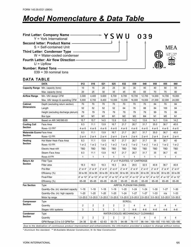
Y S W U 0 3 9MEA
First Letter: Company Name
Y = York InternationalSecond letter: Product Name
S = Self-contained UnitThird Letter: Condenser Type
W = Water-cooled condenser Fourth Letter: Air flow Direction
U = Upflow Number: Rated Tons
039 = 39 nominal tons
DATA TABLEDATA 012 016 021 025 032 039 048 050 055 060
Capacity Range Min. capacity (tons) 10 15 20 25 30 35 40 40 50 55
Max. capacity (tons) 20 25 30 35 45 55 65 70 75 80
Airflow Range Min. VAV design CFM 3,300 4,400 5,600 6,700 8,700 10,700 12,700 14,000 14,700 16,000
Max. VAV design & operating CFM 5,000 6,700 8,400 10,000 13,000 16,000 19,000 21,000 22,000 24,000
Cabinet Depth (excluding return section) 70 70 70 70 70 70 70 84 70 84Dimensions Length 52 52 52 52 64 76 88 84 100 84
Height (excluding discharge plenum) 79 79 79 79 79 79 79 99 79 99
Box type M1 M1 M1 M1 M2 M3 M4 N1 M5 N1
EER Based on ARI 340/360-93 15.7 15.7 14.5 13.9 13.8 14.2 13.6 14.1 13.6 14.2
Cooling Coil Face Area 8.3 11.1 13.9 16.7 21.7 26.7 31.7 35.0 36.7 40.0Section Rows–12 FPI* 4 or 6 4 or 6 4 or 6 4 or 6 4 or 6 4 or 6 4 or 6 4 or 6 4 or 6 4 or 6
Waterside Econo Face Area 8.3 11.1 13.9 16.7 21.7 26.7 31.7 35.0 36.7 40.0Section Rows–12 FPI 2 or 4 2 or 4 2 or 4 2 or 4 2 or 4 2 or 4 2 or 4 2 or 4 2 or 4 2 or 4
Heating Hot Water Heat–Face Area 8.3 11.1 13.9 16.7 21.7 26.7 31.7 35 36.7 40Section Rows–10 FPI 1 or 2 1 or 2 1 or 2 1 or 2 1 or 2 1 or 2 1 or 2 1 or 2 1 or 2 1 or 2
Electric Heat–kW TBD TBD TBD TBD TBD TBD TBD TBD TBD TBD
Steam–Face Area 8.3 11.1 13.9 16.7 21.7 26.7 31.7 35 36.7 40
Rows–8 FPI 1 1 1 1 1 1 1 1 1 1
Return Air Filter Type 2” or 4” PLEATED, 12” CARTRDIGESection Filter area 18.3 18.3 18.3 18.3 24.4 28.5 32.5 40.8 36.7 40.8
Pre-filter 2” or 4” 2” or 4” 2” or 4” 2” or 4” 2” or 4” 2” or 4” 2” or 4” 2” or 4” 2” or 4” 2” or 4”
Efficiency (%) 30 to 95 30 to 95 30 to 95 30 to 95 30 to 95 30 to 95 30 to 95 30 to 95 30 to 95 30 to 95
Final-Filter 4” or 12” 4” or 12” 4” or 12” 4” or 12” 4” or 12” 4” or 12” 4” or 12” 4” or 12” 4” or 12” 4” or 12”
Efficiency (%) 65–95 65–95 65–95 65–95 65–95 65–95 65–95 65–95 65–95 65–95
Fan Section Type AIRFOIL PLENUM FAN (SWSI)
Quantity–Dia. (in): standard capacity 1–18 1–18 1–18 1–18 1–20 1–24 1–24 1–30 1–27 1–30
Quantity–Dia. (in): high capacity 1–20 1–20 1–20 1–20 1–24 1–27 1–27 1–33 n/a 1–33
Motor hp range 1.0–20.0 1.0–20.0 1.0–20.0 1.0–20.0 1.5–20.0 2.0–20.0 2.0–20.0 3.0–30.0 3.0–20.0 3.0–30.0
Compressor Type SCROLLSection Quantity 2 2 2 2 2 4 4 4 4 4
Stages–VAV systems 3 3 3 3 3 4–6 4–6 4–6 4–6 4–6
Condenser Type WATER-COOLED, MECHANICALLY CLEANABLESection Quantity 2 2 2 2 2 4 4 4 4 4
GPM Range 2.0 to 3.0 GPM/Ton 24–36 32–48 42–63 50–75 64–96 78–117 96–144 100–150 110–165 120–180
Due to the dedication of cont inuous product improvement and enhancements, the info rmation provided is subject to change without notice.
* Aluminum fins standard. ** M-Available Modular Construction, N- for New Construction
Model Nomenclature & Data Table
12 YORK INTERNATIONAL
FORM 145.05-EG1 (0804)
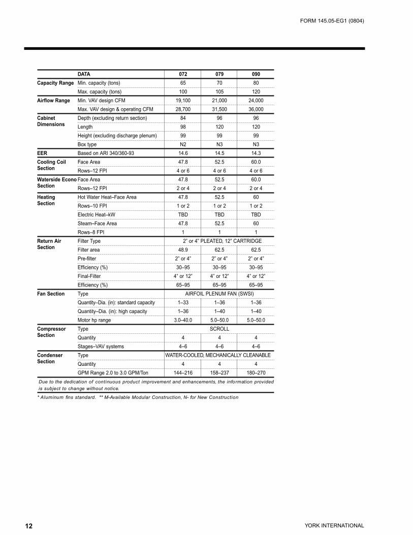
DATA 072 079 090
Capacity Range Min. capacity (tons) 65 70 80
Max. capacity (tons) 100 105 120
Airflow Range Min. VAV design CFM 19,100 21,000 24,000
Max. VAV design & operating CFM 28,700 31,500 36,000
Cabinet Depth (excluding return section) 84 96 96Dimensions Length 98 120 120
Height (excluding discharge plenum) 99 99 99
Box type N2 N3 N3
EER Based on ARI 340/360-93 14.6 14.5 14.3
Cooling Coil Face Area 47.8 52.5 60.0Section Rows–12 FPI 4 or 6 4 or 6 4 or 6
Waterside Econo Face Area 47.8 52.5 60.0Section Rows–12 FPI 2 or 4 2 or 4 2 or 4
Heating Hot Water Heat–Face Area 47.8 52.5 60Section Rows–10 FPI 1 or 2 1 or 2 1 or 2
Electric Heat–kW TBD TBD TBD
Steam–Face Area 47.8 52.5 60
Rows–8 FPI 1 1 1
Return Air Filter Type 2” or 4” PLEATED, 12” CARTRIDGESection Filter area 48.9 62.5 62.5
Pre-filter 2” or 4” 2” or 4” 2” or 4”
Efficiency (%) 30–95 30–95 30–95
Final-Filter 4” or 12” 4” or 12” 4” or 12”
Efficiency (%) 65–95 65–95 65–95
Fan Section Type AIRFOIL PLENUM FAN (SWSI)
Quantity–Dia. (in): standard capacity 1–33 1–36 1–36
Quantity–Dia. (in): high capacity 1–36 1–40 1–40
Motor hp range 3.0–40.0 5.0–50.0 5.0–50.0
Compressor Type SCROLLSection Quantity 4 4 4
Stages–VAV systems 4–6 4–6 4–6
Condenser Type WATER-COOLED, MECHANICALLY CLEANABLESection Quantity 4 4 4
GPM Range 2.0 to 3.0 GPM/Ton 144–216 158–237 180–270
Due to the dedication of continuous product improvement and enhancements, the information provided is subject to change without notice.
* Aluminum fins standard. ** M-Available Modular Construction, N- for New Construction

13YORK INTERNATIONAL
FORM 145.05-EG1 (0804)
YSWU012
4,600 CFM with 4-row Evaporator and (1)4 & (1)7 HP Scroll Compressors
EAT ECWT Condenser water D T = 15 Condenser water D T = 12 Condenser water D T = 10
TMBH SMBH LDB LWB GPM kW TMBH SMBH LDB LWB GPM kW TMBH SMBH LDB LWB GPM kW
85 145 112 57.9 56.9 23.4 8.9 147 112 57.8 56.8 29.3 8.6 148 113 57.7 56.7 35.2 8.4
80/67 88 143 111 58.1 57.0 23.3 9.2 145 112 57.9 56.9 29.2 8.9 146 112 57.8 56.8 35.1 8.7
90 142 110 58.2 57.1 23.2 9.4 144 111 58.0 57.0 29.1 9.1 145 111 58.0 56.9 35.0 8.9
85 138 112 54.7 53.7 22.4 8.8 140 113 54.6 53.6 28.1 8.5 141 114 54.5 53.5 33.8 8.4
77/64 88 137 112 54.9 53.8 22.4 9.1 138 112 54.7 53.7 28.1 8.8 139 113 54.6 53.6 33.7 8.6
90 136 111 55.0 53.9 22.3 9.3 137 112 54.8 53.8 28.0 9.0 138 112 54.7 53.7 33.7 8.8
4,600 CFM with 6-row Evaporator and (1)7 & (1)12 HP Scroll Compressors
EAT ECWT Condenser water D T = 15 Condenser water D T = 12 Condenser water D T = 10
TMBH SMBH LDB LWB GPM kW TMBH SMBH LDB LWB GPM kW TMBH SMBH LDB LWB GPM kW
85 229 150 50.3 50.1 37.4 15.2 231 151 50.0 49.9 47.0 14.7 233 152 49.9 49.7 56.4 14.4
80/67 88 226 149 50.5 50.3 37.3 15.6 229 150 50.3 50.1 46.8 15.2 231 151 50.1 49.9 56.3 14.9
90 225 148 50.6 50.4 37.2 16.0 227 149 50.4 50.2 46.7 15.5 229 150 50.3 50.1 56.1 15.2
85 217 151 47.1 46.9 35.8 15.0 220 152 46.8 46.6 44.8 14.5 221 153 46.7 46.5 53.9 14.3
77/64 88 214 150 47.3 47.1 35.7 15.5 217 151 47.1 46.9 44.7 15.0 218 152 46.9 46.7 53.7 14.7
90 213 149 47.4 47.2 35.6 15.8 215 150 47.2 47.0 44.6 15.3 217 151 47.1 46.9 53.6 15.0
YSWU016
6,100 CFM with 4-row Evaporator and (1)4 & (1)10 HP Scroll Compressors
EAT ECWT Condenser water D T = 15 Condenser water D T = 12 Condenser water D T = 10
TMBH SMBH LDB LWB GPM kW TMBH SMBH LDB LWB GPM kW TMBH SMBH LDB LWB GPM kW
85 193 149 57.9 56.8 31.3 12.1 195 149 57.7 56.7 39.3 11.8 197 150 57.6 56.6 47.2 11.5
80/67 88 191 148 58.0 57.0 31.2 12.5 193 149 57.9 56.8 39.1 12.1 195 149 57.8 56.8 47.1 11.9
90 190 147 58.1 57.0 31.1 12.8 192 148 57.9 56.9 39.0 12.4 193 149 57.9 56.8 46.9 12.1
85 184 149 54.7 53.6 30.0 12.0 186 150 54.6 53.5 37.6 11.6 187 151 54.5 53.4 45.2 11.4
77/64 88 182 148 54.8 53.8 29.9 12.4 184 149 54.7 53.6 37.5 12.0 185 150 54.6 53.6 45.1 11.8
90 181 148 54.9 53.9 29.8 12.7 182 149 54.8 53.8 37.4 12.3 184 149 54.7 53.6 45.0 12.0
6,100 CFM with 6-row Evaporator and (1)7 & (1)15 HP Scroll Compressors
EAT ECWT Condenser water D T = 15 Condenser water D T = 12 Condenser water D T = 10
TMBH SMBH LDB LWB GPM kW TMBH SMBH LDB LWB GPM kW TMBH SMBH LDB LWB GPM kW
85 276 187 52.1 51.8 45.2 18.4 279 188 51.9 51.6 56.7 17.8 281 189 51.8 51.5 68.1 17.5
80/67 88 273 186 52.3 52.0 45.1 19.1 277 187 52.1 51.8 56.5 18.4 278 188 52.0 51.7 68.0 18.1
90 271 185 52.4 52.1 45.1 19.5 274 186 52.2 51.9 56.5 18.9 276 187 52.1 51.8 67.8 18.5
85 262 187 49.0 48.6 43.2 18.3 264 189 48.8 48.5 54.1 17.7 266 190 48.6 48.3 65.0 17.3
77/64 88 259 186 49.2 48.8 43.1 18.9 262 188 49.0 48.6 54.0 18.3 263 188 48.8 48.5 64.9 17.9
90 257 185 49.3 49.0 43.1 19.4 259 186 49.1 48.8 53.9 18.7 261 187 49.0 48.7 64.8 18.3
Cooling Capacity Tables

14 YORK INTERNATIONAL
FORM 145.05-EG1 (0804)
YSWU021
8,400 CFM with 4-row Evaporator and (1)7 & (1)12 HP Scroll Compressors
EAT ECWT Condenser water D T = 15 Condenser water D T = 12 Condenser water D T = 10
TMBH SMBH LDB LWB GPM kW TMBH SMBH LDB LWB GPM kW TMBH SMBH LDB LWB GPM kW
85 251 190 57.3 56.4 40.4 15.4 253 191 57.2 56.3 50.8 15.0 255 191 57.1 56.2 61.1 14.7
80/67 88 247 188 57.5 56.5 40.3 15.9 251 190 57.3 56.4 50.5 15.5 252 190 57.2 56.3 60.8 15.2
90 246 187 57.6 56.6 40.2 16.3 249 189 57.4 56.5 50.4 15.8 250 189 57.3 56.4 60.7 15.5
85 238 190 54.2 53.2 38.7 15.3 241 192 54.0 53.1 48.6 14.8 243 192 53.9 53.0 58.5 14.5
77/64 88 236 189 54.3 53.3 38.6 15.8 238 190 54.2 53.2 48.4 15.3 240 191 54.1 53.1 58.2 15.0
90 234 188 54.4 53.4 38.5 16.1 236 189 54.3 53.3 48.3 15.6 238 190 54.2 53.2 58.1 15.3
8,400 CFM with 6-row Evaporator and (1)10 & (1)15 HP Scroll Compressors
EAT ECWT Condenser water D T = 15 Condenser water D T = 12 Condenser water D T = 10
TMBH SMBH LDB LWB GPM kW TMBH SMBH LDB LWB GPM kW TMBH SMBH LDB LWB GPM kW
85 338 231 52.4 52.2 54.9 21.8 341 232 52.2 52.0 68.9 21.1 343 233 52.1 51.9 82.8 20.7
80/67 88 334 229 52.5 52.3 54.7 22.5 338 231 52.4 52.2 68.6 21.8 340 232 52.3 52.1 82.5 21.3
90 332 228 52.7 52.5 54.6 23.0 335 230 52.5 52.3 68.5 22.3 337 231 52.4 52.2 82.4 21.8
85 320 232 49.2 49.0 52.5 21.6 324 233 49.0 48.8 65.8 20.9 326 234 48.9 48.7 79.1 20.5
77/64 88 317 231 49.3 49.1 52.5 22.3 320 232 49.2 49.0 65.6 21.6 322 233 49.1 48.9 78.9 21.2
90 315 230 49.4 49.2 52.4 22.8 319 231 49.3 49.0 65.6 22.1 320 232 49.2 49.0 78.7 21.6
YSWU025
9,100 CFM with 4-row Evaporator and (1)7 & (1)15 HP Scroll Compressors
EAT ECWT Condenser water D T = 15 Condenser water D T = 12 Condenser water D T = 10
TMBH SMBH LDB LWB GPM kW TMBH SMBH LDB LWB GPM kW TMBH SMBH LDB LWB GPM kW
85 291 222 57.8 56.8 47.2 18.6 294 223 57.7 56.6 59.1 18.0 296 224 57.6 56.6 71.1 17.6
80/67 88 287 221 57.9 56.9 47.0 19.2 290 222 57.8 56.8 59.0 18.6 292 223 57.7 56.7 70.9 18.2
90 285 220 58.1 57.0 46.9 19.6 288 221 57.9 56.9 58.8 19.0 290 222 57.8 56.8 70.8 18.6
85 275 223 54.7 53.6 45.1 18.4 278 224 54.6 53.5 56.5 17.8 280 225 54.5 53.4 67.9 17.5
77/64 88 272 221 54.8 53.7 45.0 19.1 275 223 54.7 53.6 56.4 18.5 277 223 54.6 53.5 67.8 18.1
90 270 220 54.9 53.8 44.9 19.5 273 222 54.8 53.7 56.3 18.9 275 222 54.7 53.6 67.6 18.5
9,100 CFM with 6-row Evaporator and (1)10 & (1)20 HP Scroll Compressors
EAT ECWT Condenser water D T = 15 Condenser water D T = 12 Condenser water D T = 10
TMBH SMBH LDB LWB GPM kW TMBH SMBH LDB LWB GPM kW TMBH SMBH LDB LWB GPM kW
85 372 261 53.9 53.5 61.5 26.1 376 262 53.8 53.3 77.0 25.4 378 263 53.7 53.2 92.6 24.9
80/67 88 368 259 54.1 53.7 61.4 27.0 372 260 53.9 53.5 76.9 26.2 374 262 53.8 53.4 92.4 25.7
90 366 258 54.2 53.8 61.3 27.5 369 259 54.1 53.6 76.8 26.7 372 260 53.9 53.5 92.2 26.2
85 353 262 50.7 50.3 58.9 25.9 357 264 50.6 50.1 73.8 25.1 359 265 50.5 50.0 88.7 24.6
77/64 88 350 260 50.9 50.4 58.8 26.7 353 262 50.7 50.3 73.7 25.9 356 263 50.6 50.2 88.5 25.4
90 347 259 51.0 50.6 58.7 27.3 351 261 50.8 50.4 73.5 26.5 353 262 50.7 50.3 88.4 25.9

15YORK INTERNATIONAL
FORM 145.05-EG1 (0804)
YSWU032
11,900 CFM with 4-row Evaporator and (1)12 & (1)15 HP Scroll Compressors
EAT ECWT Condenser water D T = 15 Condenser water D T = 12 Condenser water D T = 10
TMBH SMBH LDB LWB GPM kW TMBH SMBH LDB LWB GPM kW TMBH SMBH LDB LWB GPM kW
85 372 288 58.0 57.0 60.0 23.0 375 290 57.9 56.9 75.3 22.3 378 291 57.8 56.8 90.6 21.9
80/67 88 368 286 58.1 57.1 59.8 23.8 371 288 58.0 57.0 75.1 23.0 374 289 57.9 56.9 90.3 22.6
90 365 285 58.2 57.2 59.7 24.3 369 287 58.1 57.1 74.9 23.5 371 288 58.0 57.0 90.0 23.1
85 355 289 54.9 53.8 57.7 22.8 359 291 54.7 53.6 72.4 22.1 361 292 54.6 53.6 87.1 21.7
77/64 88 351 287 55.0 53.9 57.6 23.6 355 289 54.9 53.8 72.2 22.9 358 290 54.8 53.7 86.8 22.4
90 348 286 55.1 54.0 57.4 24.1 352 288 55.0 53.9 72.0 23.4 355 289 54.9 53.8 86.6 22.9
11,900 CFM with 6-row Evaporator and (1)12 & (1)25 HP Scroll Compressors
EAT ECWT Condenser water D T = 15 Condenser water D T = 12 Condenser water D T = 10
TMBH SMBH LDB LWB GPM kW TMBH SMBH LDB LWB GPM kW TMBH SMBH LDB LWB GPM kW
85 481 341 53.9 53.7 78.2 31.1 486 343 53.8 53.5 98.1 30.1 489 345 53.7 53.4 117.9 29.5
80/67 88 476 339 54.1 53.8 78.0 32.0 480 341 53.9 53.7 97.8 31.1 484 343 53.8 53.6 117.5 30.5
90 472 338 54.2 54.0 77.9 32.7 477 340 54.1 53.8 97.6 31.7 480 341 53.9 53.7 117.3 31.1
85 457 343 50.8 50.5 75.0 30.8 462 345 50.6 50.3 93.9 29.9 465 346 50.5 50.2 112.9 29.3
77/64 88 452 341 50.9 50.6 74.8 31.8 457 343 50.8 50.5 93.7 30.8 460 344 50.7 50.4 112.6 30.2
90 449 339 51.0 50.7 74.6 32.5 454 341 50.9 50.6 93.5 31.5 457 343 50.8 50.5 112.4 30.8
YSWU039
14,600 CFM with 4-row Evaporator and (2)7 & (2)10 HP Scroll Compressors
EAT ECWT Condenser water D T = 15 Condenser water D T = 12 Condenser water D T = 10
TMBH SMBH LDB LWB GPM kW TMBH SMBH LDB LWB GPM kW TMBH SMBH LDB LWB GPM kW
85 463 355 57.9 56.8 75.0 29.0 468 357 57.7 56.7 94.0 28.1 472 359 57.6 56.6 113.1 27.5
80/67 88 458 353 58.0 57.0 74.7 29.9 463 355 57.9 56.8 93.7 29.0 467 357 57.8 56.7 112.7 28.3
90 454 352 58.1 57.0 74.5 30.6 460 354 58.0 56.9 93.5 29.6 464 356 57.9 56.8 112.4 28.9
85 443 358 54.6 53.6 72.1 28.7 448 361 54.5 53.5 90.4 27.8 451 362 54.4 53.4 108.7 27.2
77/64 88 438 356 54.8 53.7 71.9 29.7 443 358 54.6 53.6 90.1 28.7 446 360 54.5 53.5 108.4 28.1
90 435 355 54.9 53.8 71.7 30.3 439.4 356.9 54.7 53.7 90.0 29.3 443 358 54.6 53.6 108.2 28.7
14,600 CFM with 6-row Evaporator and (2)10 & (2)12 HP Scroll Compressors
EAT ECWT Condenser water D T = 15 Condenser water D T = 12 Condenser water D T = 10
TMBH SMBH LDB LWB GPM kW TMBH SMBH LDB LWB GPM kW TMBH SMBH LDB LWB GPM kW
85 593.6 419.1 53.9 53.6 96.1 37.4 600 422 53.7 53.4 120.7 36.2 605 424 53.6 53.3 145.2 35.5
80/67 88 586.8 416.1 54.1 53.8 95.8 38.5 594 419 53.9 53.6 120.2 37.3 598 421 53.8 53.5 144.6 36.6
90 582.3 414.2 54.2 53.9 95.5 39.4 589 417 54.0 53.7 119.8 38.1 594 419 53.9 53.6 144.2 37.3
85 564.9 421.7 50.7 50.3 92.2 37.0 572 425 50.5 50.1 115.7 35.8 576 427 50.4 50.0 139.3 35.1
77/64 88 558.7 418.9 50.9 50.5 91.9 38.2 566 422 50.6 50.3 115.2 37.0 570 424 50.5 50.2 138.7 36.2
90 554.8 417.2 51.0 50.6 91.6 39.0 561 420 50.8 50.4 115.0 37.7 566 422 50.6 50.3 138.3 36.9
16 YORK INTERNATIONAL
FORM 145.05-EG1 (0804)
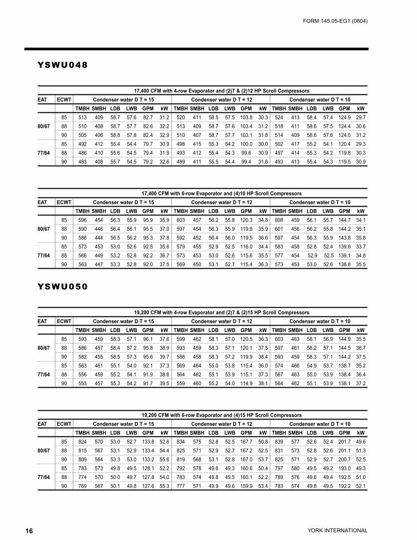
YSWU048
17,400 CFM with 4-row Evaporator and (2)7 & (2)12 HP Scroll Compressors
EAT ECWT Condenser water D T = 15 Condenser water D T = 12 Condenser water D T = 10
TMBH SMBH LDB LWB GPM kW TMBH SMBH LDB LWB GPM kW TMBH SMBH LDB LWB GPM kW
85 513 409 58.7 57.6 82.7 31.2 520 411 58.5 57.5 103.8 30.3 524 413 58.4 57.4 124.9 29.7
80/67 88 510 408 58.7 57.7 82.6 32.2 513 409 58.7 57.6 103.4 31.2 518 411 58.6 57.5 124.4 30.6
90 505 406 58.8 57.8 82.4 32.9 510 407 58.7 57.7 103.1 31.8 514 409 58.6 57.6 124.0 31.2
85 492 412 55.4 54.4 79.7 30.9 498 415 55.3 54.2 100.0 30.0 502 417 55.2 54.1 120.4 29.3
77/64 88 486 410 55.6 54.5 79.4 31.9 493 412 55.4 54.3 99.6 30.9 497 414 55.3 54.2 119.8 30.3
90 483 408 55.7 54.5 79.2 32.6 489 411 55.5 54.4 99.4 31.6 493 413 55.4 54.3 119.5 30.9
17,400 CFM with 6-row Evaporator and (4)10 HP Scroll Compressors
EAT ECWT Condenser water D T = 15 Condenser water D T = 12 Condenser water D T = 10
TMBH SMBH LDB LWB GPM kW TMBH SMBH LDB LWB GPM kW TMBH SMBH LDB LWB GPM kW
85 596 454 56.3 55.9 95.9 35.9 603 457 56.2 55.8 120.3 34.8 608 459 56.1 55.7 144.7 34.1
80/67 88 590 446 56.4 56.1 95.5 37.0 597 454 56.3 55.9 119.8 35.9 601 456 56.2 55.8 144.2 35.1
90 586 444 56.5 56.2 95.3 37.8 592 452 56.4 56.0 119.5 36.6 597 454 56.3 55.9 143.8 35.8
85 573 453 53.0 52.6 92.5 35.6 579 455 52.9 52.5 116.0 34.4 583 458 52.8 52.4 139.6 33.7
77/64 88 566 449 53.2 52.8 92.2 36.7 573 453 53.0 52.6 115.6 35.5 577 454 52.9 52.5 139.1 34.8
90 563 447 53.3 52.8 92.0 37.5 569 450 53.1 52.7 115.4 36.3 573 453 53.0 52.6 138.8 35.5
YSWU050
19,200 CFM with 4-row Evaporator and (2)7 & (2)15 HP Scroll Compressors
EAT ECWT Condenser water D T = 15 Condenser water D T = 12 Condenser water D T = 10
TMBH SMBH LDB LWB GPM kW TMBH SMBH LDB LWB GPM kW TMBH SMBH LDB LWB GPM kW
85 593 459 58.3 57.1 96.1 37.6 599 462 58.1 57.0 120.5 36.3 603 463 58.1 56.9 144.9 35.5
80/67 88 586 457 58.4 57.2 95.8 38.9 593 459 58.3 57.1 120.1 37.5 597 461 58.2 57.1 144.5 36.7
90 582 455 58.5 57.3 95.6 39.7 588 458 58.3 57.2 119.9 38.4 593 459 58.3 57.1 144.2 37.5
85 563 461 55.1 54.0 92.1 37.3 569 464 55.0 53.8 115.4 36.0 574 466 54.9 53.7 138.7 35.2
77/64 88 556 459 55.2 54.1 91.9 38.6 564 462 55.1 53.9 115.1 37.3 567 463 55.0 53.9 138.4 36.4
90 553 457 55.3 54.2 91.7 39.5 559 460 55.2 54.0 114.9 38.1 564 462 55.1 53.9 138.1 37.2
19,200 CFM with 6-row Evaporator and (4)15 HP Scroll Compressors
EAT ECWT Condenser water D T = 15 Condenser water D T = 12 Condenser water D T = 10
TMBH SMBH LDB LWB GPM kW TMBH SMBH LDB LWB GPM kW TMBH SMBH LDB LWB GPM kW
85 824 570 53.0 52.7 133.8 52.6 834 575 52.8 52.5 167.7 50.8 839 577 52.6 52.4 201.7 49.6
80/67 88 815 567 53.1 52.9 133.4 54.4 825 571 52.9 52.7 167.2 52.5 831 573 52.8 52.6 201.1 51.3
90 809 564 53.3 53.0 133.2 55.6 819 568 53.1 52.8 167.0 53.7 825 571 52.9 52.7 200.7 52.5
85 783 573 49.8 49.5 128.1 52.2 792 578 49.6 49.3 160.6 50.4 797 580 49.5 49.2 193.0 49.3
77/64 88 774 570 50.0 49.7 127.8 54.0 783 574 49.8 49.5 160.1 52.2 789 576 49.6 49.4 192.5 51.0
90 769 567 50.1 49.8 127.6 55.3 777 571 49.9 49.6 159.9 53.4 783 574 49.8 49.5 192.2 52.1

17YORK INTERNATIONAL
FORM 145.05-EG1 (0804)
YSWU055
20,300 CFM with 4-row Evaporator and (4)12 HP Scroll Compressors
EAT ECWT Condenser water D T = 15 Condenser water D T = 12 Condenser water D T = 10
TMBH SMBH LDB LWB GPM kW TMBH SMBH LDB LWB GPM kW TMBH SMBH LDB LWB GPM kW
85 655 496 57.5 56.6 105.4 39.8 663 499 57.4 56.5 132.4 38.6 668 501 57.3 56.4 159.4 37.9
80/67 88 647 492 57.7 56.8 105.0 41.0 656 496 57.5 56.6 131.8 39.8 661 498 57.4 56.5 158.7 39.0
90 643 490 57.8 56.8 104.7 41.8 651 494 57.6 56.7 131.4 40.6 656 496 57.5 56.6 158.2 39.8
85 627 499 54.4 53.4 101.5 39.4 635 502 54.2 53.2 127.5 38.2 640 505 54.1 53.1 153.5 37.5
77/64 88 620 496 54.5 53.5 101.1 40.6 627 499 54.4 53.4 126.9 39.4 632 501 54.2 53.3 152.8 38.6
90 615 493 54.6 53.6 100.8 41.4 622 497 54.4 53.5 126.5 40.2 627 499 54.4 53.4 152.3 39.3
20,300 CFM with 6-row Evaporator and (4)15 HP Scroll Compressors
EAT ECWT Condenser water D T = 15 Condenser water D T = 12 Condenser water D T = 10
TMBH SMBH LDB LWB GPM kW TMBH SMBH LDB LWB GPM kW TMBH SMBH LDB LWB GPM kW
85 833 587 53.7 53.5 135.0 52.6 842 591 53.5 53.3 169.3 50.9 848 593 53.4 53.2 203.6 49.7
80/67 88 824 583 53.9 53.6 134.6 54.4 834 587 53.7 53.4 168.8 52.6 840 590 53.6 53.3 203.0 51.4
90 818 581 54.0 53.7 134.4 55.7 827 584 53.8 53.6 168.5 53.8 834 587 53.7 53.4 202.6 52.5
85 791 590 50.5 50.2 129.4 52.3 801 594 50.3 50.0 162.1 50.5 806 596 50.2 49.9 194.9 49.4
77/64 88 785 587 50.6 50.3 129.3 54.1 792 590 50.5 50.2 161.7 52.2 798 593 50.4 50.1 194.4 51.0
90 780 585 50.8 50.5 129.1 55.4 788 589 50.6 50.3 161.8 53.5 792 590 50.5 50.2 194.0 52.2
YSWU060
22,000 CFM with 4-row Evaporator and (2)10 & (2)15 HP Scroll Compressors
EAT ECWT Condenser water D T = 15 Condenser water D T = 12 Condenser water D T = 10
TMBH SMBH LDB LWB GPM kW TMBH SMBH LDB LWB GPM kW TMBH SMBH LDB LWB GPM kW
85 700 537 57.8 56.8 113.4 44.0 708 540 57.7 56.7 142.3 42.6 714 543 57.6 56.6 171.1 41.6
80/67 88 693 534 57.9 56.9 113.0 45.5 701 538 57.8 56.8 141.8 44.0 705 540 57.7 56.7 170.5 43.0
90 688 532 58.0 57.0 112.8 46.5 696 536 57.9 56.9 141.5 44.9 701 537 57.8 56.8 170.2 43.9
85 670 542 54.6 53.5 109.3 43.7 678 546 54.4 53.4 136.9 42.3 682 547 54.3 53.3 164.7 41.3
77/64 88 664 539 54.7 53.6 109.0 45.2 671 542 54.6 53.5 136.6 43.7 675 544 54.5 53.4 164.3 42.7
90 658 537 54.8 53.7 108.8 46.2 665 540 54.7 53.6 136.4 44.6 671 542 54.6 53.5 163.9 43.6
22,000 CFM with 6-row Evaporator and (2)15 & (2)20 HP Scroll Compressors
EAT ECWT Condenser water D T = 15 Condenser water D T = 12 Condenser water D T = 10
TMBH SMBH LDB LWB GPM kW TMBH SMBH LDB LWB GPM kW TMBH SMBH LDB LWB GPM kW
85 926 642 53.5 53.0 151.5 61.7 936 646 53.3 52.9 189.9 59.7 942 648 53.2 52.8 228.3 58.4
80/67 88 916 637 53.6 53.2 151.1 63.7 926 642 53.5 53.0 189.4 61.6 932 644 53.3 52.9 227.7 60.3
90 909 634 53.8 53.3 150.8 65.0 919 639 53.6 53.2 189.1 62.9 926 642 53.5 53.0 227.3 61.6
85 879 645 50.3 49.8 145.0 61.2 888 649 50.1 49.7 181.7 59.2 894 652 50.0 49.6 218.5 57.9
77/64 88 869 640 50.5 50.0 144.7 63.2 880 645 50.3 49.8 181.2 61.1 885 648 50.1 49.7 217.89 59.8
90 863 638 50.6 50.1 144.4 64.5 873 642 50.4 49.9 181.0 62.4 880 645 50.3 49.8 217.5 61.1
18 YORK INTERNATIONAL
FORM 145.05-EG1 (0804)
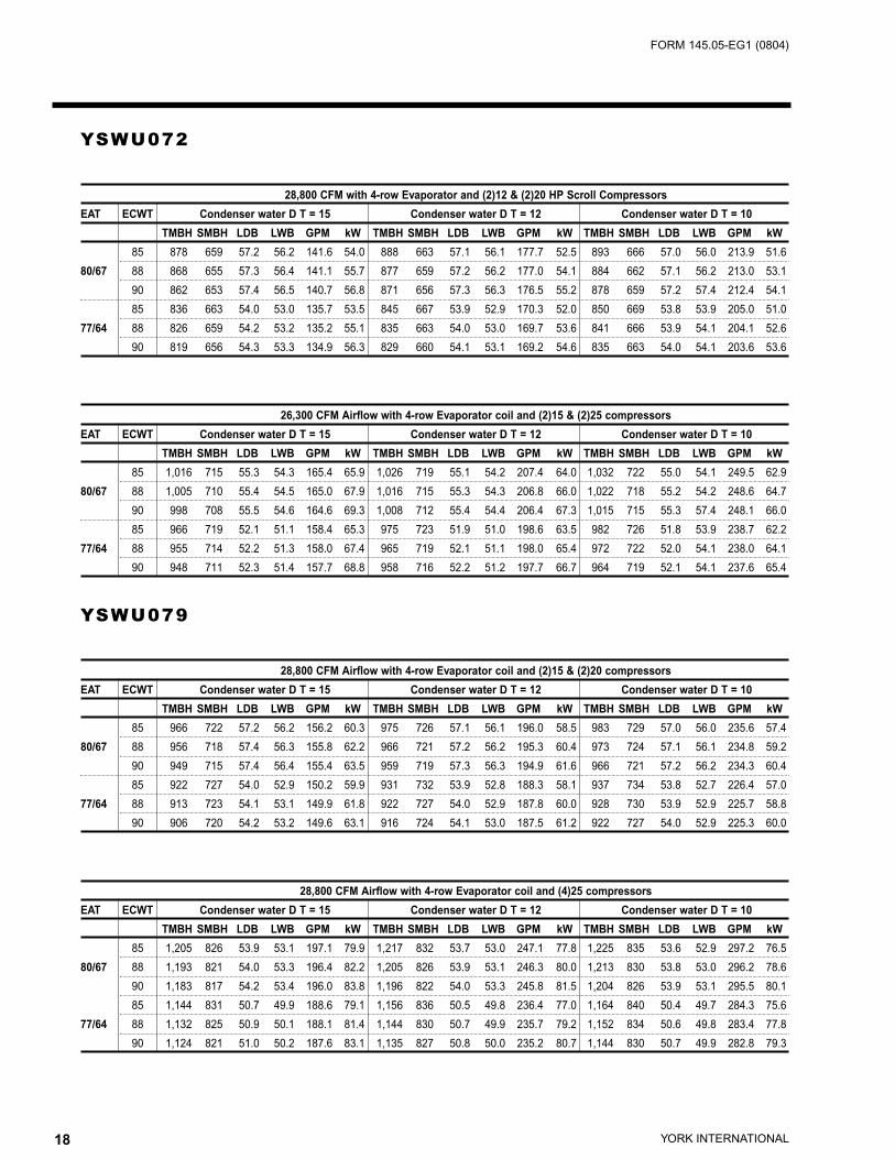
YSWU072
28,800 CFM with 4-row Evaporator and (2)12 & (2)20 HP Scroll Compressors
EAT ECWT Condenser water D T = 15 Condenser water D T = 12 Condenser water D T = 10
TMBH SMBH LDB LWB GPM kW TMBH SMBH LDB LWB GPM kW TMBH SMBH LDB LWB GPM kW
85 878 659 57.2 56.2 141.6 54.0 888 663 57.1 56.1 177.7 52.5 893 666 57.0 56.0 213.9 51.6
80/67 88 868 655 57.3 56.4 141.1 55.7 877 659 57.2 56.2 177.0 54.1 884 662 57.1 56.2 213.0 53.1
90 862 653 57.4 56.5 140.7 56.8 871 656 57.3 56.3 176.5 55.2 878 659 57.2 57.4 212.4 54.1
85 836 663 54.0 53.0 135.7 53.5 845 667 53.9 52.9 170.3 52.0 850 669 53.8 53.9 205.0 51.0
77/64 88 826 659 54.2 53.2 135.2 55.1 835 663 54.0 53.0 169.7 53.6 841 666 53.9 54.1 204.1 52.6
90 819 656 54.3 53.3 134.9 56.3 829 660 54.1 53.1 169.2 54.6 835 663 54.0 54.1 203.6 53.6
26,300 CFM Airflow with 4-row Evaporator coil and (2)15 & (2)25 compressors
EAT ECWT Condenser water D T = 15 Condenser water D T = 12 Condenser water D T = 10
TMBH SMBH LDB LWB GPM kW TMBH SMBH LDB LWB GPM kW TMBH SMBH LDB LWB GPM kW
85 1,016 715 55.3 54.3 165.4 65.9 1,026 719 55.1 54.2 207.4 64.0 1,032 722 55.0 54.1 249.5 62.9
80/67 88 1,005 710 55.4 54.5 165.0 67.9 1,016 715 55.3 54.3 206.8 66.0 1,022 718 55.2 54.2 248.6 64.7
90 998 708 55.5 54.6 164.6 69.3 1,008 712 55.4 54.4 206.4 67.3 1,015 715 55.3 57.4 248.1 66.0
85 966 719 52.1 51.1 158.4 65.3 975 723 51.9 51.0 198.6 63.5 982 726 51.8 53.9 238.7 62.2
77/64 88 955 714 52.2 51.3 158.0 67.4 965 719 52.1 51.1 198.0 65.4 972 722 52.0 54.1 238.0 64.1
90 948 711 52.3 51.4 157.7 68.8 958 716 52.2 51.2 197.7 66.7 964 719 52.1 54.1 237.6 65.4
YSWU079
28,800 CFM Airflow with 4-row Evaporator coil and (2)15 & (2)20 compressors
EAT ECWT Condenser water D T = 15 Condenser water D T = 12 Condenser water D T = 10
TMBH SMBH LDB LWB GPM kW TMBH SMBH LDB LWB GPM kW TMBH SMBH LDB LWB GPM kW
85 966 722 57.2 56.2 156.2 60.3 975 726 57.1 56.1 196.0 58.5 983 729 57.0 56.0 235.6 57.4
80/67 88 956 718 57.4 56.3 155.8 62.2 966 721 57.2 56.2 195.3 60.4 973 724 57.1 56.1 234.8 59.2
90 949 715 57.4 56.4 155.4 63.5 959 719 57.3 56.3 194.9 61.6 966 721 57.2 56.2 234.3 60.4
85 922 727 54.0 52.9 150.2 59.9 931 732 53.9 52.8 188.3 58.1 937 734 53.8 52.7 226.4 57.0
77/64 88 913 723 54.1 53.1 149.9 61.8 922 727 54.0 52.9 187.8 60.0 928 730 53.9 52.9 225.7 58.8
90 906 720 54.2 53.2 149.6 63.1 916 724 54.1 53.0 187.5 61.2 922 727 54.0 52.9 225.3 60.0
28,800 CFM Airflow with 4-row Evaporator coil and (4)25 compressors
EAT ECWT Condenser water D T = 15 Condenser water D T = 12 Condenser water D T = 10
TMBH SMBH LDB LWB GPM kW TMBH SMBH LDB LWB GPM kW TMBH SMBH LDB LWB GPM kW
85 1,205 826 53.9 53.1 197.1 79.9 1,217 832 53.7 53.0 247.1 77.8 1,225 835 53.6 52.9 297.2 76.5
80/67 88 1,193 821 54.0 53.3 196.4 82.2 1,205 826 53.9 53.1 246.3 80.0 1,213 830 53.8 53.0 296.2 78.6
90 1,183 817 54.2 53.4 196.0 83.8 1,196 822 54.0 53.3 245.8 81.5 1,204 826 53.9 53.1 295.5 80.1
85 1,144 831 50.7 49.9 188.6 79.1 1,156 836 50.5 49.8 236.4 77.0 1,164 840 50.4 49.7 284.3 75.6
77/64 88 1,132 825 50.9 50.1 188.1 81.4 1,144 830 50.7 49.9 235.7 79.2 1,152 834 50.6 49.8 283.4 77.8
90 1,124 821 51.0 50.2 187.6 83.1 1,135 827 50.8 50.0 235.2 80.7 1,144 830 50.7 49.9 282.8 79.3

19YORK INTERNATIONAL
FORM 145.05-EG1 (0804)
YSWU090
33,000 CFM Airflow with 4-row Evaporator coil and (2)15 + (2)25 compressors
EAT ECWT Condenser water D T = 15 Condenser water D T = 12 Condenser water D T = 10
TMBH SMBH LDB LWB GPM kW TMBH SMBH LDB LWB GPM kW TMBH SMBH LDB LWB GPM kW
85 1,077 815 57.6 56.5 173.9 66.6 1,089 820 57.4 56.4 218.3 64.8 1,096 823 57.3 56.3 262.6 63.7
80/67 88 1,066 810 57.7 56.6 173.3 68.6 1,077 815 57.6 56.5 217.4 66.7 1,084 817 57.5 56.4 261.6 65.5
90 1,057 807 57.8 56.7 172.9 70.0 1,069 811 57.6 56.6 216.9 68.0 1,076 815 57.6 56.5 260.9 66.7
85 1,028 822 54.3 53.3 167.2 66.0 1,039 827 54.2 53.1 209.7 64.2 1,046 830 54.1 53.1 252.2 63.0
77/64 88 1,017 817 54.5 53.4 166.6 68.0 1,028 822 54.3 53.3 209.0 66.1 1,035 825 54.2 53.2 251.3 64.9
90 1,011 814 54.5 53.5 166.3 69.4 1,021 819 54.4 53.3 208.5 67.4 1,028 822 54.3 53.3 250.7 66.2
33,000 CFM Airflow with 6-row Evaporator coil and (4)25
EAT ECWT Condenser water D T = 15 Condenser water D T = 12 Condenser water D T = 10
TMBH SMBH LDB LWB GPM kW TMBH SMBH LDB LWB GPM kW TMBH SMBH LDB LWB GPM kW
85 1,319 938 54.2 53.9 212.9 81.5 1,332 944 54.0 53.7 267.2 79.5 1,341 948 53.9 53.6 321.6 78.2
80/67 88 1,304 932 54.3 54.0 212.0 83.7 1,318 938 54.2 53.9 266.0 81.6 1,326 941 54.1 53.8 320.2 80.3
90 1,295 928 54.4 54.1 211.4 85.3 1,308 934 54.3 54.0 265.3 83.1 1,317 938 54.2 53.9 319.3 81.7
85 1,256 945 50.9 50.6 204.2 80.6 1,268 951 50.8 50.4 256.1 78.5 1,277 954 50.6 50.3 308.1 77.2
77/64 88 1,243 939 51.1 50.8 203.4 82.9 1,256 945 50.9 50.6 255.2 80.7 1,264 948 50.8 50.5 307.0 79.3
90 1,234 935 51.2 50.9 202.9 84.4 1,247 941 51.0 50.7 254.5 82.2 1,256 945 50.9 50.6 306.1 80.7
20 YORK INTERNATIONAL
FORM 145.05-EG1 (0804)
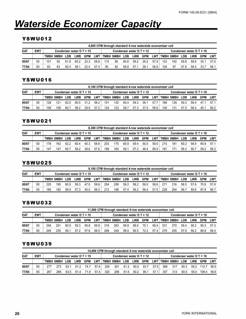
YSWU0124,600 CFM through standard 4-row waterside economizer coil
EAT EWT Condenser water D T = 15 Condenser water D T = 12 Condenser water D T = 10
TMBH SMBH LDB LWB GPM LWT TMBH SMBH LDB LWB GPM LWT TMBH SMBH LDB LWB GPM LWT
80/67 50 101 92 61.9 60.2 23.3 58.6 115 99 60.6 59.2 29.2 57.9 123 102 59.8 58.6 35.1 57.0
77/64 50 83 83 60.4 58.1 22.4 57.4 95 92 58.8 57.1 28.1 56.8 104 97 57.9 56.5 33.7 56.1
YSWU0166,100 CFM through standard 4-row waterside economizer coil
EAT EWT Condenser water D T = 15 Condenser water D T = 12 Condenser water D T = 10
TMBH SMBH LDB LWB GPM LWT TMBH SMBH LDB LWB GPM LWT TMBH SMBH LDB LWB GPM LWT
80/67 50 128 121 62.0 60.5 31.2 58.2 151 132 60.4 59.3 39.1 57.7 168 139 59.3 58.4 47.1 57.1
77/64 50 108 108 60.7 58.2 29.9 57.2 124 123 58.7 57.3 37.5 56.6 140 131 57.5 56.4 45.1 56.2
YSWU0218,300 CFM through standard 4-row waterside economizer coil
EAT EWT Condenser water D T = 15 Condenser water D T = 12 Condenser water D T = 10
TMBH SMBH LDB LWB GPM LWT TMBH SMBH LDB LWB GPM LWT TMBH SMBH LDB LWB GPM LWT
80/67 50 178 163 62.2 60.4 40.3 58.8 203 175 60.9 59.4 50.5 58.0 215 181 60.2 58.9 60.8 57.1
77/64 50 147 147 60.7 58.2 38.6 57.6 168 164 59.1 57.3 48.4 56.9 181 171 58.3 56.7 58.2 56.2
YSWU0259,100 CFM through standard 4-row waterside economizer coil
EAT EWT Condenser water D T = 15 Condenser water D T = 12 Condenser water D T = 10
TMBH SMBH LDB LWB GPM LWT TMBH SMBH LDB LWB GPM LWT TMBH SMBH LDB LWB GPM LWT
80/67 50 225 195 60.5 59.3 47.0 59.6 254 208 59.2 58.2 59.0 58.6 271 216 58.5 57.6 70.9 57.6
77/64 50 185 182 58.9 57.3 45.0 58.2 213 196 57.4 56.2 56.4 57.5 228 204 56.7 55.6 67.8 56.7
YSWU03211,900 CFM through standard 4-row waterside economizer coil
EAT EWT Condenser water D T = 15 Condenser water D T = 12 Condenser water D T = 10
TMBH SMBH LDB LWB GPM LWT TMBH SMBH LDB LWB GPM LWT TMBH SMBH LDB LWB GPM LWT
80/67 50 294 251 60.9 59.3 59.8 59.8 318 263 59.9 58.6 75.1 58.4 331 270 59.4 58.2 90.3 57.3
77/64 50 245 235 59.1 57.2 57.6 58.5 268 249 58.0 56.5 72.2 57.4 279 255 57.6 56.2 86.8 56.4
YSWU03914,600 CFM through standard 4-row waterside economizer coil
EAT EWT Condenser water D T = 15 Condenser water D T = 12 Condenser water D T = 10
TMBH SMBH LDB LWB GPM LWT TMBH SMBH LDB LWB GPM LWT TMBH SMBH LDB LWB GPM LWT
80/67 50 277 273 63.1 61.2 74.7 57.4 329 301 61.3 60.0 93.7 57.0 366 317 60.3 59.2 112.7 56.5
77/64 50 267 266 63.5 61.4 71.9 57.4 320 296 61.6 60.2 90.1 57.1 357 313 60.5 59.4 108.4 56.6
Waterside Economizer Capacity

21YORK INTERNATIONAL
FORM 145.05-EG1 (0804)
YSWU04817,400 CFM through standard 4-row waterside economizer coil
EAT EWT Condenser water D T = 15 Condenser water D T = 12 Condenser water D T = 10
TMBH SMBH LDB LWB GPM LWT TMBH SMBH LDB LWB GPM LWT TMBH SMBH LDB LWB GPM LWT
80/67 50 325 319 63.4 61.3 82.6 57.8 380 349 61.8 60.2 103.4 57.3 419 367 60.9 59.5 124.4 56.7
77/64 50 282 282 62.1 58.7 79.4 57.1 318 318 60.1 58.0 99.6 56.4 353 345 59.0 57.3 119.8 55.9
YSWU05019,200 CFM through standard 4-row waterside economizer coil
EAT EWT Condenser water D T = 15 Condenser water D T = 12 Condenser water D T = 10
TMBH SMBH LDB LWB GPM LWT TMBH SMBH LDB LWB GPM LWT TMBH SMBH LDB LWB GPM LWT
80/67 50 399 373 62.4 60.6 95.8 58.3 454 401 61.1 59.6 120.1 57.5 494 420 60.2 59.0 144.5 56.8
77/64 50 338 338 60.8 58.2 91.9 57.3 387 379 59.1 57.3 115.1 56.7 416 396 58.3 56.8 138.4 56.0
YSWU05520,300 CFM through standard 4-row waterside economizer coil
EAT EWT Condenser water D T = 15 Condenser water D T = 12 Condenser water D T = 10
TMBH SMBH LDB LWB GPM LWT TMBH SMBH LDB LWB GPM LWT TMBH SMBH LDB LWB GPM LWT
80/67 50 384 378 63.1 61.2 105.0 57.3 454 415 61.5 60.1 131.8 56.9 502 437 60.5 59.3 158.7 56.3
77/64 50 334 334 61.8 58.6 101.1 56.6 378 378 59.8 57.9 126.9 56.0 422 410 58.7 57.1 152.8 55.5
YSWU06022,000 CFM through standard 4-row waterside economizer coil
EAT EWT Condenser water D T = 15 Condenser water D T = 12 Condenser water D T = 10
TMBH SMBH LDB LWB GPM LWT TMBH SMBH LDB LWB GPM LWT TMBH SMBH LDB LWB GPM LWT
80/67 50 449 426 62.4 60.7 113.0 57.9 521 463 60.9 59.6 141.8 57.3 581 491 59.8 58.7 170.5 56.8
77/64 50 435 419 62.7 60.9 109.0 58.0 507 457 61.2 59.8 136.6 57.4 570 485 60.0 58.9 164.3 56.9
YSWU07226,300 CFM through standard 4-row waterside economizer coil
EAT EWT Condenser water D T = 15 Condenser water D T = 12 Condenser water D T = 10
TMBH SMBH LDB LWB GPM LWT TMBH SMBH LDB LWB GPM LWT TMBH SMBH LDB LWB GPM LWT
80/67 50 572 525 61.9 60.3 141.1 58.1 639 556 60.8 59.4 177.0 57.2 684 578 60.1 58.9 213.0 56.4
77/64 50 477 477 60.3 58.0 135.2 57.1 541 524 58.9 57.2 169.7 56.4 576 545 58.2 56.7 204.1 55.6
YSWU07928,800 CFM through standard 4-row waterside economizer coil
EAT EWT Condenser water D T = 15 Condenser water D T = 12 Condenser water D T = 10
TMBH SMBH LDB LWB GPM LWT TMBH SMBH LDB LWB GPM LWT TMBH SMBH LDB LWB GPM LWT
80/67 50 677 599 61.1 59.7 155.8 58.7 753 636 60.0 58.8 195.3 57.7 798 658 59.3 58.3 234.8 56.8
77/64 50 583 568 59.1 57.3 149.9 57.8 636 600 58.1 56.7 187.8 56.8 671 621 57.4 56.2 225.7 55.9

22 YORK INTERNATIONAL
FORM 145.05-EG1 (0804)
YSWU09033,000 CFM through standard 4-row waterside economizer coil
EAT EWT Condenser water D T = 15 Condenser water D T = 12 Condenser water D T = 10
TMBH SMBH LDB LWB GPM LWT TMBH SMBH LDB LWB GPM LWT TMBH SMBH LDB LWB GPM LWT
80/67 50 790 691 61.0 59.6 173.3 59.1 864 728 60.0 58.8 217.4 57.9 909 750 59.4 58.3 261.6 56.9
77/64 50 684 659 58.9 57.1 166.6 58.2 732 688 58.1 56.6 209.0 57.0 765 709 57.5 56.3 251.3 56.1
23YORK INTERNATIONAL
FORM 145.05-EG1 (0804)
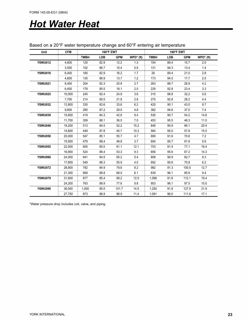
Based on a 20°F water temperature change and 60°F entering air temperature
Unit CFM 160°F EWT 180°F EWT
TMBH LDB GPM WPD* (ft) TMBH LDB GPM WPD* (ft)
YSWU012 4,800 120 82.9 12.2 1.3 154 89.4 15.7 2.0
3,500 102 86.7 10.4 0.9 131 94.3 13.4 1.4
YSWU016 6,400 160 82.9 16.2 1.7 26 89.4 21.0 2.8
4,600 135 86.9 13.7 1.2 173 94.5 17.7 2.0
YSWU021 8,400 204 82.3 20.8 2.7 263 88.7 26.9 4.2
6,400 178 85.5 18.1 2.0 229 92.8 23.4 3.3
YSWU025 10,000 245 82.4 24.9 3.6 315 88.8 32.2 5.6
7,700 214 85.5 21.8 2.8 275 92.8 28.2 4.4
YSWU032 12,800 330 83.6 33.6 6.2 420 90.1 43.0 9.7
9,600 285 87.2 29.0 4.8 362 94.6 37.0 7.4
YSWU039 15,600 419 84.3 42.6 9.4 530 90.7 54.2 14.8
11,700 359 88.1 36.5 7.0 453 95.5 46.3 11.0
YSWU048 19,200 513 84.5 52.2 15.2 646 90.9 66.1 20.4
14,800 449 87.8 45.7 10.3 564 95.0 57.8 15.5
YSWU050 20,000 547 85.1 55.7 4.7 690 91.6 70.6 7.2
15,500 479 88.4 48.8 3.7 604 95.7 61.8 5.6
YSWU055 22,000 600 85.0 61.1 12.1 753 91.4 77.1 18.4
16,900 524 88.4 53.3 9.3 656 95.6 67.2 14.3
YSWU060 24,000 641 84.5 65.2 5.4 808 90.9 82.7 8.3
17,800 549 88.3 55.9 4.0 692 95.6 70.8 6.2
YSWU072 28,800 782 84.9 79.6 8.2 982 91.3 100.5 12.7
21,300 669 88.8 68.0 6.1 839 96.1 85.8 9.4
YSWU079 31,600 877 85.4 89.2 12.0 1,096 91.8 112.1 19.4
24,200 763 88.9 77.6 9.8 953 96.1 97.5 15.0
YSWU090 36,000 1,000 85.5 101.7 14.5 1,250 91.8 127.9 21.9
27,750 873 88.9 88.9 11.4 1,091 96.0 111.6 17.1
*Water pressure drop includes coil, valve, and piping.
Hot Water Heat

24 YORK INTERNATIONAL
FORM 145.05-EG1 (0804)
Selections based on 60°F entering air temperature
Unit CFM 10 psi
TMBH LDB Steam Flow Rate (lb/hr)
YSWU012 4,800 200 98.4 210
3,500 175 106 106
YSWU016 6,400 263 97.9 276
4,600 228 105.7 239
YSWU021 8,400 338 97.1 355
6,400 301 103.4 316
YSWU025 10,000 406 97.4 426
7,700 364 103.6 382
YSWU032 12,800 524 97.7 549
9,600 464 104.5 486
YSWU039 15,600 647 97.7 678
11,700 569 104.9 597
YSWU048 19,200 688 93.1 722
14,800 630 99.2 661
YSWU050 20,000 827 98.1 867
15,500 754 104.9 791
YSWU055 22,000 807 93.8 847
16,900 737 100.2 773
YSWU060 24,000 857 104.4 899
17,800 953 96.6 1000
YSWU072 28,800 1,175 94.3 1232
21,300 1,023 104.3 1073
YSWU079 31,600 1,082 91.6 1135
24,200 990 97.7 1039
YSWU090 36,000 1,422 96.4 1492
27,750 1,298 103.1 1362
Steam Heat

25YORK INTERNATIONAL
FORM 145.05-EG1 (0804)
Model YSWU 012, 016, 032 NOTES021 & 025
CFM Range 3,300 to 10,000 8,700– Modular : construction allows the unit to be broken13,000 into sections to fit thru a 3’ door or small freight elevator.
Tonnage Range 10 to 35 30–45 New/Retrofit : ability to be broken into smaller sections.Unit Style Modular ModularA 1 Fan Section Width 34 34 1 Add 1” for 1” access panelsB1 Coil Section Width 34 34 Add 2” for 2” access panelsC 1 & 3 Installed Width 68 68 Add 3” for 3” access panelsD Discharge Opening Width 20 20E Discharge Opening Length 40 48 2 Add 2” for 1” access panelsF 1 Installed Height 78 78 Add 4” for 2” access panelsG 1 Electrical Section Width 22 22 Add 6” for 3” access panelsH Base Length (no panels) 50 62I 2 Installed Length 50 62 3 Add 6” for 4” pre-filtersJ Inlet Height 44 58 1/2 Add 12” for 4” pre-filters with 4” final filtersK Inlet Length 60 60 Add 22” for 4” pre-filters and 12” final filtersL Drain Connection 1 1/8 1 1/8M Condenser Water Supply/Return 2 1/8 2 5/8 C F Consult FactoryAll dimensions in inches
Unit Dimensions 012, 016, 021, 025 & 032

26 YORK INTERNATIONAL
FORM 145.05-EG1 (0804)
Model YSWU 039 048 050 & 055 072 079 060 & 090
CFM Range 10,700– 12,700– 14,000– 14,700– 19,100– 21,000–16,000 19,000 24,000 22,000 28,700 36,000
Tonnage Range 35–55 40–65 40–80 50–75 65–100 70–120Unit Style Modular Modular New/Retrofit Modular New/Retrofit New/Retrofit
A 1 Fan Section Width 34 34 CF 34 CF CFB 1 Coil Section Width 34 34 CF 34 CF CFC 1&3 Installed Width 68 68 82 68 82 94D Discharge Opening Width 20 20 24 20 24 24 NOTES
E Discharge Opening Length 64 76 72 84 90 112 (see page 25)F 1 Installed Height 78 78 98 78 98 98G 1 Electrical Section Width 19 5/8 19 5/8 19 5/8 19 5/8 19 5/8 19 5/8H Base Length (no panels) 74 86 82 98 96 118I 2 Installed Length 74 86 82 98 96 118J Inlet Height 58 1/2 58 1/2 73 1/2 58 1/2 73 1/2 73 1/2K Inlet Length 60 60 80 60 80 80L Drain Connection 1 1/8 1 1/8 1 1/8 1 1/8 1 1/8 1 1/8M Condenser Water Supl/Ret. 2 5/8 2 5/8 2 5/8 3 1/8 3 1/8 3 1/8All dimensions in inches
Unit Dimensions 039 to 090
27YORK INTERNATIONAL
FORM 145.05-EG1 (0804)
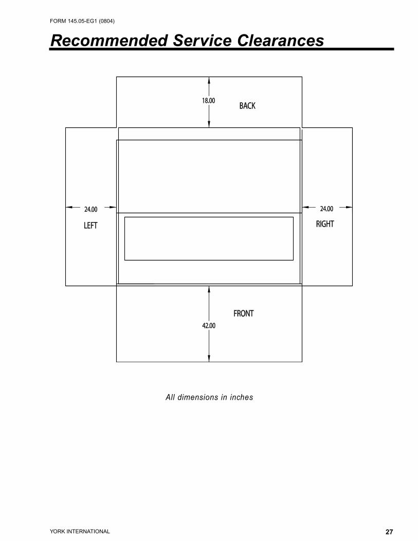
Recommended Service Clearances
All dimensions in inches
28 YORK INTERNATIONAL
FORM 145.05-EG1 (0804)
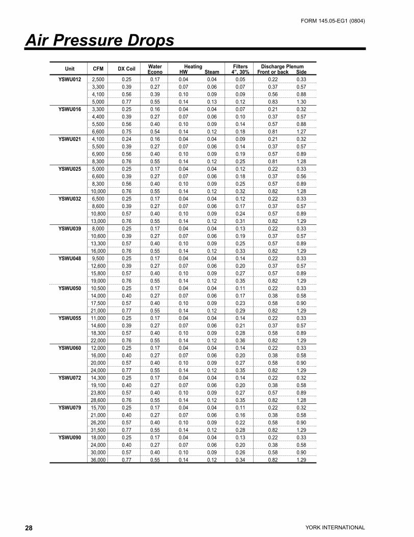
Water Heating Filters Discharge PlenumUnit CFM DX CoilEcono HW Steam 4”, 30% Front or back Side
YSWU012 2,500 0.25 0.17 0.04 0.04 0.05 0.22 0.333,300 0.39 0.27 0.07 0.06 0.07 0.37 0.574,100 0.56 0.39 0.10 0.09 0.09 0.56 0.885,000 0.77 0.55 0.14 0.13 0.12 0.83 1.30
YSWU016 3,300 0.25 0.16 0.04 0.04 0.07 0.21 0.324,400 0.39 0.27 0.07 0.06 0.10 0.37 0.575,500 0.56 0.40 0.10 0.09 0.14 0.57 0.886,600 0.75 0.54 0.14 0.12 0.18 0.81 1.27
YSWU021 4,100 0.24 0.16 0.04 0.04 0.09 0.21 0.325,500 0.39 0.27 0.07 0.06 0.14 0.37 0.576,900 0.56 0.40 0.10 0.09 0.19 0.57 0.898,300 0.76 0.55 0.14 0.12 0.25 0.81 1.28
YSWU025 5,000 0.25 0.17 0.04 0.04 0.12 0.22 0.336,600 0.39 0.27 0.07 0.06 0.18 0.37 0.568,300 0.56 0.40 0.10 0.09 0.25 0.57 0.8910,000 0.76 0.55 0.14 0.12 0.32 0.82 1.28
YSWU032 6,500 0.25 0.17 0.04 0.04 0.12 0.22 0.338,600 0.39 0.27 0.07 0.06 0.17 0.37 0.5710,800 0.57 0.40 0.10 0.09 0.24 0.57 0.8913,000 0.76 0.55 0.14 0.12 0.31 0.82 1.29
YSWU039 8,000 0.25 0.17 0.04 0.04 0.13 0.22 0.3310,600 0.39 0.27 0.07 0.06 0.19 0.37 0.5713,300 0.57 0.40 0.10 0.09 0.25 0.57 0.8916,000 0.76 0.55 0.14 0.12 0.33 0.82 1.29
YSWU048 9,500 0.25 0.17 0.04 0.04 0.14 0.22 0.3312,600 0.39 0.27 0.07 0.06 0.20 0.37 0.5715,800 0.57 0.40 0.10 0.09 0.27 0.57 0.8919,000 0.76 0.55 0.14 0.12 0.35 0.82 1.29
YSWU050 10,500 0.25 0.17 0.04 0.04 0.11 0.22 0.3314,000 0.40 0.27 0.07 0.06 0.17 0.38 0.5817,500 0.57 0.40 0.10 0.09 0.23 0.58 0.9021,000 0.77 0.55 0.14 0.12 0.29 0.82 1.29
YSWU055 11,000 0.25 0.17 0.04 0.04 0.14 0.22 0.3314,600 0.39 0.27 0.07 0.06 0.21 0.37 0.5718,300 0.57 0.40 0.10 0.09 0.28 0.58 0.8922,000 0.76 0.55 0.14 0.12 0.36 0.82 1.29
YSWU060 12,000 0.25 0.17 0.04 0.04 0.14 0.22 0.3316,000 0.40 0.27 0.07 0.06 0.20 0.38 0.5820,000 0.57 0.40 0.10 0.09 0.27 0.58 0.9024,000 0.77 0.55 0.14 0.12 0.35 0.82 1.29
YSWU072 14,300 0.25 0.17 0.04 0.04 0.14 0.22 0.3219,100 0.40 0.27 0.07 0.06 0.20 0.38 0.5823,800 0.57 0.40 0.10 0.09 0.27 0.57 0.8928,600 0.76 0.55 0.14 0.12 0.35 0.82 1.28
YSWU079 15,700 0.25 0.17 0.04 0.04 0.11 0.22 0.3221,000 0.40 0.27 0.07 0.06 0.16 0.38 0.5826,200 0.57 0.40 0.10 0.09 0.22 0.58 0.9031,500 0.77 0.55 0.14 0.12 0.28 0.82 1.29
YSWU090 18,000 0.25 0.17 0.04 0.04 0.13 0.22 0.3324,000 0.40 0.27 0.07 0.06 0.20 0.38 0.5830,000 0.57 0.40 0.10 0.09 0.26 0.58 0.9036,000 0.77 0.55 0.14 0.12 0.34 0.82 1.29
Air Pressure Drops

29YORK INTERNATIONAL
FORM 145.05-EG1 (0804)
18” PLENUM FAN – MODELS 012, 016, 021, 025
20” PLENUM FAN - MODEL 032
6.0
5.5
5.0
4.5
4.0
3.5
3.0
2.5
2.0
1.5
1.0
0.5
0.00 1,000 2,000 3,000 4,000 5,000 6,000 7,000 8,000 9,000
CFM
Stat
ic P
ress
ure
(inch
es o
f w
ater
)
6.0
5.5
5.0
4.5
4.0
3.5
3.0
2.5
2.0
1.5
1.0
0.5
0.00 2,000 4,000 6,000 8,000 10,000 12,000 14,000
CFM
Stat
ic P
ress
ure
(inch
es o
f w
ater
)
1300
1500
0.75
1.0
1.5
2.0
3.0 5.0 7.5 10.0 15.0
1700
1900
2100
2300 2500 2700 2900
1.0
1.5
2.0
3.0
5.0 7.5 10.0 15.0 20.0
1200
1400
1600
1800
2000
2200 2400 2600 2800 3000
Do not select. Class III fan required, consult factory.
Do not select.
Fan Curves

30 YORK INTERNATIONAL
FORM 145.05-EG1 (0804)
24” PLENUM FAN – MODELS 032, 039, 048
27” PLENUM FAN – MODELS 039, 048, 055
6.0
5.5
5.0
4.5
4.0
3.5
3.0
2.5
2.0
1.5
1.0
0.5
0.00 2,000 4,000 6,000 8,000 10,000 12,000 14,000 16,000
CFM
Stat
ic P
ress
ure
(inch
es o
f w
ater
)
6.0
5.5
5.0
4.5
4.0
3.5
3.0
2.5
2.0
1.5
1.0
0.5
0.0
0 2,000 4,000 6,000 8,000 10,000 12,000 14,000 16,000 18,000 20,000 22,000 24,000CFM
Stat
ic P
ress
ure
(inch
es o
f w
ater
)
1.0
2.0
3.0
5.0 7.5 10.0 15.0 20.0
900
1050
1200
1350
1500
1650
1800 1950 2100 2250
2.0
3.0
5.0 7.5 10.0 15.0 20.0 25.0 30.0
850
1000
1150
1300
1450
1600 1750 1900 2050 2200 2350
Do not select.
Do not select. Class III fan required, consult factory.

31YORK INTERNATIONAL
FORM 145.05-EG1 (0804)
30” PLENUM FAN – MODELS 050, 060
33” PLENUM FAN – MODELS 050, 060, 072
6.0
5.5
5.0
4.5
4.0
3.5
3.0
2.5
2.0
1.5
1.0
0.5
0.00 2,000 4,000 6,000 8,000 10,000 12,000 14,000 16,000 18,000 20,000 22,000 24,000 26,000
CFM
Stat
ic P
ress
ure
(inch
es o
f w
ater
)
6.0
5.5
5.0
4.5
4.0
3.5
3.0
2.5
2.0
1.5
1.0
0.5
0.00 4,000 8,000 12,000 16,000 20,000 24,000 28,000 32,000
CFM
Stat
ic P
ress
ure
(inch
es o
f w
ater
)
2.0
3.0
5.0
7.5 10.0 15.0 20.0 25.0
800
1000
1200
14001600 1800
2.0
3.0
5.0
7.5
10.0 15.0 20.0 25.0 30.0
700
800
900
1000
1100
1200
1300 1400 1500 1600
Do not select.
Do not select.
32 YORK INTERNATIONAL
FORM 145.05-EG1 (0804)
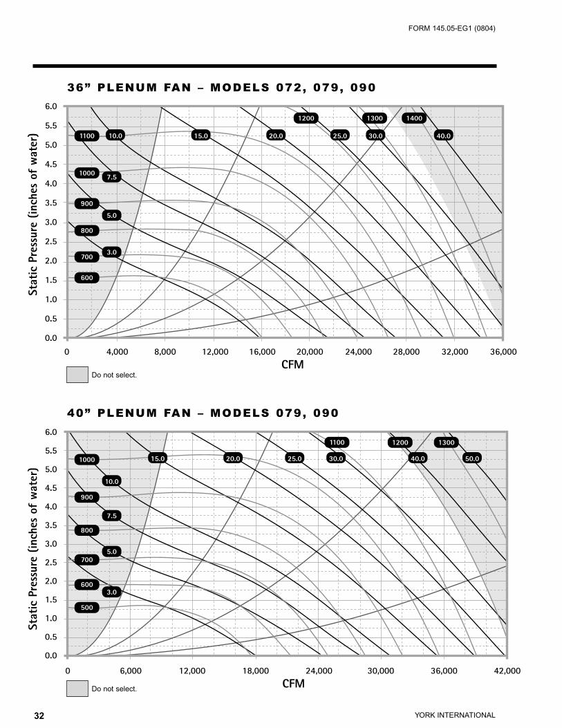
36” PLENUM FAN – MODELS 072, 079, 090
40” PLENUM FAN – MODELS 079, 090
6.0
5.5
5.0
4.5
4.0
3.5
3.0
2.5
2.0
1.5
1.0
0.5
0.00 4,000 8,000 12,000 16,000 20,000 24,000 28,000 32,000 36,000
CFM
Stat
ic P
ress
ure
(inch
es o
f w
ater
)
6.0
5.5
5.0
4.5
4.0
3.5
3.0
2.5
2.0
1.5
1.0
0.5
0.0
0 6,000 12,000 18,000 24,000 30,000 36,000 42,000CFM
Stat
ic P
ress
ure
(inch
es o
f w
ater
)
3.0
5.0
7.5
10.0 15.0 20.0 25.0 30.0 40.0
600
700
800
900
1000
1100
1200 1300 1400
3.0
5.0
7.5
10.0
15.0 20.0 25.0 30.0 40.0 50.0
500
600
700
800
900
1000
1100 1200 1300
Do not select.
Do not select.

33YORK INTERNATIONAL
FORM 145.05-EG1 (0804)
11 HP
14 HP 17 HP 19 HP 22 HP 25 HP27 HP
37 HP
Condenser Water Pressure Drop – 0012 through 0032
Water Flow – GPM
Pre
ssu
re D
rop
– F
eet
of
WC
20 30 40 50 60 70 80 90 100 110 120
18
16
14
12
10
8
6
4
2
0
Water Pressure Drop Tables
MinWater Flow 15 20 25 30 35 40 45 50 55
Max Water Flow 45 60 70 80 90 100 110 120 130
Compressors* (1)4 & (1)7 (1)4 & (1)10 (1)7 & (1)10 (1)7 & (1)12 (1)7 & (1)15 (1)10 & (1)15 (1)12 & (1)15 (1)12 & (1)20 (1)12 & (1) 25
GPM 11 HP 14 HP 17 HP 19 HP 22 HP 25 HP 27 HP 32 HP 37 HP
20 1.56 1.17 - - - - - - -
25 2.42 1.80 - - - - - - -
30 3.46 2.57 2.04 - - - - - -
35 4.68 3.48 2.75 2.28 - - - - -
40 6.09 4.51 3.57 2.95 2.52 - - - -
45 7.68 5.68 4.48 3.70 3.16 2.78 - - -
50 - 6.98 5.50 4.54 3.87 3.40 3.05 - -
55 - 8.41 6.62 5.45 4.65 4.08 3.66 3.33 -
60 - 9.97 7.83 6.45 5.49 4.82 4.31 3.93 3.63
65 - - 9.15 7.52 6.41 5.61 5.02 4.57 4.21
70 - - 10.56 8.68 7.38 6.46 5.77 5.25 4.84
75 - - - 9.91 8.43 7.37 6.58 5.98 5.51
80 - - - 11.22 9.54 8.33 7.43 6.75 6.22
85 - - - - 10.72 9.35 8.34 7.57 6.97
90 - - - - 11.96 10.43 9.29 8.43 7.76
95 - - - - - 11.56 10.29 9.34 8.59
100 - - - - - 12.74 11.34 10.28 9.46
105 - - - - - - 12.44 11.27 10.36
110 - - - - - - 13.59 12.31 11.31
115 - - - - - - - 13.38 12.29
120 - - - - - - - 14.50 13.32
125 - - - - - - - - 14.38
130 - - - - - - - - 15.47
YSWU012 – YSWU032
32 HP
*(Quantity) Nominal HP & (Quantity) Nominal HP

34 YORK INTERNATIONAL
FORM 145.05-EG1 (0804)
Min Water Flow 51 57 66 72 75 81 90 96 105 111 120
Max Water Flow 136 152 176 192 200 216 240 256 280 296 320
Compressors* (2)7 & (2)10 (2)7 & (2)12 (2)7 & (2)15 (4)12 (2)10 & (2)15 (2)12 & (2)15 (4)15 (2)12 & (2)20 (2)15 & (2)20 (2)12 & (2)25 (2)15 & (2)25
GPM 34 HP 38 HP 44 HP 48 HP 50 HP 54 HP 60 HP 64 HP 70 HP 74 HP 80 HP
50 2.91 - - - - - - - - - -
57 3.75 2.96 - - - - - - - - -
66 5.00 3.93 3.55 - - - - - - - -
72 5.92 4.65 4.20 3.56 - - - - - - -
75 6.41 5.03 4.55 3.85 4.16 - - - - - -
81 7.45 5.84 5.27 4.46 4.82 4.15 - - - - -
90 9.14 7.15 6.46 5.45 5.90 5.07 4.75 - - - -
96 10.37 8.11 7.32 6.17 6.68 5.74 5.37 4.19 - - -
105 12.35 9.64 8.70 7.32 7.94 6.80 6.37 4.99 4.67 - -
111 13.76 10.73 9.68 8.14 8.83 7.57 7.08 5.55 5.20 4.90
120 16.02 12.48 11.25 9.45 10.26 8.78 8.21 6.45 6.04 5.69 5.39
136 20.44 15.90 14.32 12.01 13.05 11.14 10.42 8.20 7.68 7.23 6.84
152 - 19.71 17.75 14.85 16.16 13.78 12.87 10.16 9.51 8.95 8.46
176 - - 23.54 19.66 21.41 18.22 17.01 13.48 12.60 11.85 11.20
192 - - - 23.22 25.30 21.50 20.07 15.94 14.90 14.00 13.22
200 - - - - 27.37 23.24 21.68 17.24 16.11 15.14 14.29
216 - - - - - 26.92 25.10 20.00 18.68 17.54 16.56
240 - - - - - - 30.67 24.50 22.87 21.47 20.25
256 - - - - - - - 27.74 25.88 24.29 22.91
280 - - - - - - - - 30.74 28.84 27.19
296 - - - - - - - - - 32.08 30.23
34 HP 38 HP44 HP
48 HP
50 HP
54 HP60 HP
64 HP70 HP
74 HP
80 HP
Condenser Water Pressure Drop – 0039 through 0060
Water Flow – GPM
Pre
ssu
re D
rop
– F
eet
of
WC
50 75 100 125 150 175 200 225 250 275 300
35
30
25
20
15
10
5
0
YSWU039 – 0060
*(Quantity) Nominal HP & (Quantity) Nominal HP

35YORK INTERNATIONAL
FORM 145.05-EG1 (0804)
60 HP64 HP
74 HP80 HP 90 HP 100 HP
Condenser Water Pressure Drop – 0055 through 0090
Water Flow – GPM
Pre
ssu
re D
rop
– F
eet
of
WC
100 150 200 250 300
35
30
25
20
15
10
5
0
70 HP
Min Water Flow 90 96 105 111 120 135 150
Max Water Flow 240 256 280 296 320 360 400
Compressors* (4)15 (2)12 & (2)20 (2)15 & (2)20 (2)12 & (2)25 (2)15 & (2)25 (2)20 & (2)25 (4)25
GPM 60 HP 64 HP 70 HP 74 HP 80 HP 90 HP 100 HP
90 5.63 - - - - - -
96 6.40 5.03 - - - - -
105 7.65 6.01 5.40 - - - -
111 8.54 6.71 6.03 5.46 - - -
120 9.98 7.84 7.04 6.37 5.80 - -
135 12.61 9.90 8.89 8.04 7.32 6.27 -
150 15.56 12.20 10.95 9.91 9.02 7.71 6.78
200 27.58 21.61 19.38 17.52 15.94 13.51 11.87
240 - 31.03 27.83 25.14 22.86 19.29 16.92
256 - - 31.63 28.57 25.98 21.88 19.19
280 - - - - 31.02 26.07 22.84
296 - - - - - 29.05 25.45
320 - - - - - - 29.62
YSWU055 – YSWU090
*(Quantity) Nominal HP & (Quantity) Nominal HP
36 YORK INTERNATIONAL
FORM 145.05-EG1 (0804)
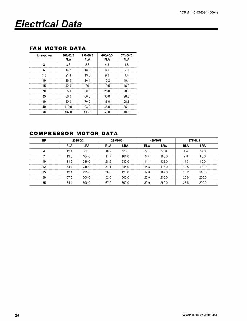
COMPRESSOR MOTOR DATAHP 208/60/3 230/60/3 460/60/3 575/60/3
RLA LRA RLA LRA RLA LRA RLA LRA
4 12.1 91.0 10.9 91.0 5.5 50.0 4.4 37.0
7 19.6 164.0 17.7 164.0 9.7 100.0 7.8 80.0
10 31.2 239.0 28.2 239.0 14.1 125.0 11.3 80.0
12 34.4 245.0 31.1 245.0 15.5 113.0 12.5 100.0
15 42.1 425.0 38.0 425.0 19.0 187.0 15.2 148.0
20 57.5 500.0 52.0 500.0 26.0 250.0 20.8 200.0
25 74.4 500.0 67.2 500.0 32.0 250.0 25.6 200.0
FAN MOTOR DATAHorsepower 208/60/3 230/60/3 460/60/3 575/60/3
FLA FLA FLA FLA
3 8.8 8.6 4.3 3.8
5 14.2 13.2 6.6 5.9
7.5 21.4 19.6 9.8 8.4
10 28.6 26.4 13.2 10.4
15 42.0 39 19.5 16.0
20 55.0 50.0 25.0 20.0
25 66.0 60.0 30.0 26.0
30 80.0 70.0 35.0 28.5
40 110.0 93.0 46.0 36.1
50 137.0 118.0 59.0 46.5
Electrical Data

37YORK INTERNATIONAL
FORM 145.05-EG1 (0804)
Unit Weights 012 016 021 025 032 039 048 050 055 060 072 079 090
Cooling Coil Section
Cabinet 451 456 461 466 529 593 656 818 720 823 911 1135 1140
Evaporative Coil 168 206 244 282 350 418 486 528 554 592 694 761 855
Waterside Economizer Section
4 Row, 12 FPI 267 305 343 381 457 549 627 679 705 743 855 932 1,026
Water Weight 35 47 58 70 91 112 133 147 154 168 201 221 252
Heating Section
Hot Water Heat 63 83 105 126 163 201 238 263 276 301 359 395 451
Water Weight 11 14 18 22 28 35 41 46 48 52 62 68 78
Steam 63 83 105 126 163 201 238 263 276 301 359 395 451
Electric Heat 21 21 21 21 21 21 42 42 42 42 42 42 42
Return Air Section
Filters
4”, 30% 182 182 182 182 213 244 276 352 306 352 401 477 477
Fan Section
Cabinet 451 456 461 466 529 593 656 818 720 823 911 1135 1140
Fan and Base
18” 203 203 203 203 - - - - - - - - -
20” 213 213 213 213 213 - - - - - - - -
22” - - - - 233 233 - - - - - - -
24” - - - - - 285 285 - - - - - -
27” - - - - - 428 428 - 428 - - - -
30” - - - - - - - 472 - 472 - - -
33” - - - - - - - 598 - 598 598 - -
36” - - - - - - - - - - 685 685 685
40” - - - - - - - - - - - 920 920
44” - - - - - - - - - - - - -
Motor HP
2 64 - - - - - - - - - - - -
3 100 100 - - - - - - - - - - -
5 117 117 117 117 - - - - - - - - -
7.5 194 194 194 194 194 194 - 194 - - - - -
10 213 213 213 213 213 213 213 213 213 213 213 213 -
15 - - 326 326 326 326 326 326 326 326 326 326 326
20 - - - - 368 368 368 368 368 368 368 368 368
25 - - - - - - 495 495 495 495 495 495 495
30 - - - - - - - - - 519 519 519 519
40 - - - - - - - - - - 602 602 602
50 - - - - - - - - - - - - -
Variable Frequency Drive
2 5 - - - - - - - - - - - -
3 8 8 - - - - - - - - - - -
5 13 13 13 13 - - - - - - - - -
7.5 51 51 51 51 51 51 - 51 - - - - -
10 51 51 51 51 51 51 51 51 51 51 51 51 -
15 - - 66 66 66 66 66 66 66 66 66 66 66
20 - - - - 66 66 66 66 66 66 66 66 66
25 - - - - - - 106 106 106 106 106 106 106
30 - - - - - - - - - 106 106 106 106
40 - - - - - - - - - - 106 106 106
50 - - - - - - - - - - - - -
Weights
38 YORK INTERNATIONAL
FORM 145.05-EG1 (0804)
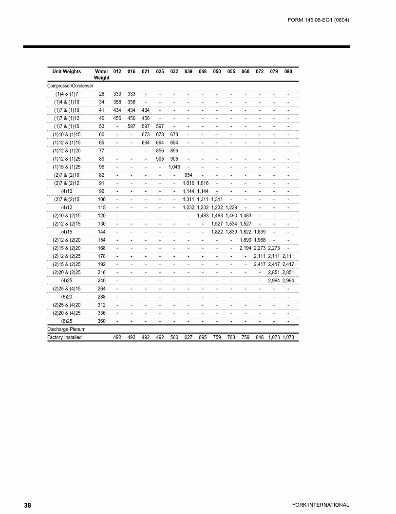
Unit Weights Water 012 016 021 025 032 039 048 050 055 060 072 079 090
Weight
Compressor/Condenser
(1)4 & (1)7 26 333 333 - - - - - - - - - - -
(1)4 & (1)10 34 358 358 - - - - - - - - - - -
(1)7 & (1)10 41 434 434 434 - - - - - - - - - -
(1)7 & (1)12 46 456 456 456 - - - - - - - - - -
(1)7 & (1)15 53 - 597 597 597 - - - - - - - - -
(1)10 & (1)15 60 - - 673 673 673 - - - - - - - -
(1)12 & (1)15 65 - - 694 694 694 - - - - - - - -
(1)12 & (1)20 77 - - - 856 856 - - - - - - - -
(1)12 & (1)25 89 - - - 905 905 - - - - - - - -
(1)15 & (1)25 96 - - - - 1,046 - - - - - - - -
(2)7 & (2)10 82 - - - - - 954 - - - - - - -
(2)7 & (2)12 91 - - - - - 1,016 1,016 - - - - - -
(4)10 96 - - - - - 1,144 1,144 - - - - - -
(2)7 & (2)15 106 - - - - - 1,311 1,311 1,311 - - - - -
(4)12 115 - - - - - 1,232 1,232 1,232 1,229 - - - -
(2)10 & (2)15 120 - - - - - - 1,483 1,483 1,490 1,483 - - -
(2)12 & (2)15 130 - - - - - - - 1,527 1,534 1,527 - - -
(4)15 144 - - - - - - - 1,822 1,839 1,822 1,839 - -
(2)12 & (2)20 154 - - - - - - - - - 1,899 1,968 - -
(2)15 & (2)20 168 - - - - - - - - - 2,194 2,273 2,273 -
(2)12 & (2)25 178 - - - - - - - - - - 2,111 2,111 2,111
(2)15 & (2)25 192 - - - - - - - - - - 2,417 2,417 2,417
(2)20 & (2)25 216 - - - - - - - - - - - 2,851 2,851
(4)25 240 - - - - - - - - - - - 2,994 2,994
(2)25 & (4)15 264 - - - - - - - - - - - - -
(6)20 288 - - - - - - - - - - - - -
(2)25 & (4)20 312 - - - - - - - - - - - - -
(2)20 & (4)25 336 - - - - - - - - - - - - -
(6)25 360 - - - - - - - - - - - - -
Discharge Plenum
Factory Installed 492 492 492 492 560 627 695 759 763 759 846 1,073 1,073

39YORK INTERNATIONAL
FORM 145.05-EG1 (0804)
CABINET CONSTRUCTION
Each unit shall be completely factory assembled and shipped in one piece [three pieces]. Theunit framework shall be fabricated from formed steel members of 10-gauge and 16-gauge. Thegalvanized steel base includes 10-gauge formed steel members for structural strength, easyinstallation, and to prevent damage caused during rigging. Exterior cabinetry and access panelsshall be constructed with a minimum of 18-gauge steel. Exterior panels shall be fabricated frompre-painted galvanized steel for aesthetics. Paint finish shall be beige color. Integral lifting brack-ets shall be installed on the unit base with holes able to accept hooks.
For quick and easy adjustments of refrigerant components and high/low voltage electrical com-ponents without interrupting operation during the occupied mode, unit shall include sections tolocate these items out of the air stream. The unit shall incorporate removable access panels onall sides of the unit to allow service access to the coil section, fan section, condenser section,compressors and control components. The electrical panel access doors shall be hinged andshall be small enough to open within the service clearance of the unit. Each panel shall besecured with latches. The latches should not require tools for panel removal except those overhigh voltage electrical components and mopving parts. The exterior panels shall be insulatedwith 1-inch [2-inch, 3-inch], 1.5 pcf [3.0 pcf] density, heavy mat-faced fiberglass insulation. Thistype of insulation is used for better acoustics and efficiency. The insulation shall be held in placewith 22-gauge perforated galvanized sheet metal, which shall provide additional sound attenua-tion. [Solid 22-gauge galvanized steel liners shall be provided to allow wash down.]
Installation manual, start-up form, operating bulletin, maintenance bulletin, and a hard copy ofthe electrical wiring diagrams are supplied inside each unit. Units shall have labels to indicatecaution areas for servicing the unit. The data plate (nameplate) is permanently attached to theunit on the external panel next to the user interface panel on the front of the unit.
DISCHARGE PLENUM
Units shall be provided with an optional acoustical discharge plenum shipped factory-mounted [loosefor field installation]. The duct opening(s) in the discharge plenum shall be located for horizontal ductconnection(s). Single [Multiple] duct opening size(s) and location(s) shall be coordinated with the fac-tory. Duct openings for the discharge plenum shall not require field cutting or modifications.
The plenum shall be constructed of formed 16-gauge galvanized steel. The exterior panels shallbe fabricated from 18-gauge pre-painted galvanized steel. The plenum wall shall be insulatedwith 1-inch [2-inch, 3-inch or 4-inch], 1.5 pcf [3.0 pcf] density fiberglass acoustical insulation. [Foracoustical purposes, the interior walls of the plenum shall be lined with 22-gauge, galvanizedsteel, perforated liner.] [A fiber barrier made from Tedlar shall be placed between the perforatedliners and the face of the insulation.]
Closed cell gasket and clear silicon caulking shall be placed between the unit and the dischargeplenum to prevent air leakage. Brackets anchored with bolts shall attach the plenum to the unit.When the plenum is to be shipped loose, mounting hardware including bolts, brackets, gasketand caulking shall be provided from the factory. It shall be shipped inside the plenum.
RETURN SECTION
Filters—The filter section shall be constructed of 16-gauge painted galvanized steel. The filtersshall be face-loading (removable from the back of the unit). [For servicing the filters from eitherside, hinged and latched access doors shall be provided on both sides of the unit.] To improveindoor air quality and reduce filter changes, 4” [12”] thick filters shall be provided with a maximumface velocity of 500 FPM. ASHRAE Standard 52.1-1992 shall determine the efficiency of the filter.The minimum efficiency shall be MERV 8 [9, 10, 11, 12, 13 or 14] (efficiency 30% (65%, 85%, or95%)). The construction of the filter shall have media resistant to water consisting of mini pleats.
Mechanical Specifications

40 YORK INTERNATIONAL
FORM 145.05-EG1 (0804)
Airside Economizer Mixing Box—For ducted return applications, a mixing box with integral lowleak dampers shall be provided. This section shall be shipped separate from the unit for fieldinstallation. The mixing box panels shall be made from 18-gauge painted galvanized steel. Theframe casing shall be constructed of 16-gauge galvanized steel. The section shall includedampers for the return and outdoor air. Dampers shall be opposed, airfoil shaped, and sealed byvinyl gasket along the edges for low leakage. The dampers shall be fabricated from 16-gaugegalvanized steel and rotate on nylon bearings. An integral filter section shall be included.
The return and outdoor air opening locations and sizes shall be coordinated with the factory,which include the side(s), top, and/or bottom. A control actuator with linkages for the returnair dampers and another for the outdoor air dampers shall be factory installed. The dampersactuator shall modulate in response to the cooling load during the economizer mode. The out-door air damper and return air damper shall be controlled in a reverse-acting fashion by theunit controller.
Economizer operation shall be controlled to maximize free cooling operation based on dry-bulbset point comparison, enthalpy set point comparison, or return and outdoor air comparativeenthalpy control. If outdoor air is suitable for cooling, the outdoor air dampers shall modulate tomaintain temperature set point. If the outdoor air cannot satisfy the cooling load, mechanicalcooling shall assist the pre-cooling to achieve temperature set point. To maximize energy sav-ings, the economizer shall pre-cool until disabled by the enthalpy or temperature. When theeconomizer is disabled, the outdoor air dampers shall be set to the minimum position of 15%(keypad adjustable).
COOLING COIL SECTION
Direct Expansion (DX)—DX cooling coils shall be ARI certified and constructed of seamless0.50-inch outside diameter copper tubing with a minimum wall thickness of 0.016-inches. Thecopper tubes shall be mechanically expanded to the aluminum fins. Coils shall be a minimum of4-rows [6-rows or 8-rows], with a minimum of 12 fins per inch. An adjustable thermal expansionvalve (TXV) including an external equalizer shall feed each circuit. The TXV shall be sized tooperate with a minimum entering condenser water temperatures of 55°F. The coil shall be leaktested with high-pressure nitrogen in a warm water bath. To prevent refrigerant control issues atlow load conditions, the minimum design face velocity shall be a minimum 400 FPM.
The coil section shall include an integral drain pan constructed of 16-gauge, type 304 stainlesssteel. The minimum depth of the drain pan shall be 2 inches. The drain pan shall be sloped inall directions towards the condensate drain connection to provide positive drainage. The unitshall include a factory installed drain line and drain trap with a cleanout for field installation toensure adequate access to the trap. Convenient access to the coil, drain pan, and drain trap forinspection and cleaning shall be accessible.
Waterside Economizer—Waterside economizer cooling coils shall be ARI certified and con-structed of seamless 0.50-inch outside diameter copper tubing with a wall thickness of 0.016-inches. The copper tubes shall be mechanically expanded to the aluminum fins. Coils shall be aminimum of 4-rows, with a minimum of 12 fins per inch. The circuiting of the coil shall be suchto allow the lowest water pressure drop. Waterside economizer water coils shall have a vent anddrain. The coil shall be provided to be chemically [and mechanically] cleanable. The coil shall beleak tested with high-pressure nitrogen in a warm water bath. The complete economizer pack-age, including the coil, valves, and piping shall be rated for 400-psig waterside working pressure.
To control the water flow through the coil, a factory installed modulating control valve packageshall be provided. A valve package includes the valve, actuator, wiring, and piping internal to theunit. The condenser water piping connections shall be located inside, close to the exterior of theunit, located for easy connection to the building risers. One set of connections (one for inlet andone for outlet) is needed for each unit.

41YORK INTERNATIONAL
FORM 145.05-EG1 (0804)
Economizer operation shall be controlled to maximize free cooling operation as the entering con-denser water is colder than the entering air (mixed air = outdoor air + return air) temperature to theunit. A default differential of 5°F (keypad adjustable between 5°F to 10°F) is needed to prevent inter-mediate changes. If the condenser water is suitable for cooling, the economizer valve shall modu-late to maintain temperature set point. If the cold condenser water cannot satisfy the cooling load,mechanical cooling shall assist the pre-cooling to achieve temperature set point. To maximize ener-gy savings, the economizer shall pre-cool until disabled when the condenser water becomes toowarm compared to the entering air temperature. When the economizer is disabled, the economizervalve shall shut and the condenser valve shall open to allow 100% water flow through the condenser.
When the unit is in the unoccupied mode, the economizer is disabled and the economizer valveis always closed. The condenser valve can be set to either closed or 100% open. If the con-denser valve is closed, called variable waterflow condenser mode, the system water flow shallbe reduced, thus saving pumping energy. If the condenser valve is set to closed in the unoccu-pied mode, the valves shall be controlled to work independent of the economizer valve. If thecondenser valve is set to be 100% open in the unoccupied mode, the valves shall work in reverseacting. This is constant waterflow condeser mode.
[A non-averaging type freezestat shall be factory installed. When the freezestat senses theentering air temperature is below the set point, the unit shall be put into the unoccupiedmode and the economizer valve shall be driven to 100% open and the condenser valveshall be driven closed.]
HEATING SECTION (OPTIONAL)
Hot Water—Hot water heating coils shall be ARI certified and constructed of seamless 0.50-inchoutside diameter copper tubing with a wall thickness of 0.016-inches. The copper tubes shall bemechanically expanded to the aluminum fins. Coils shall be a minimum of 1-row, with a minimumof 12 fins per inch. The circuiting of the coil shall be such to allow the lowest water pressure drop.Hot water coils shall have a vent and drain. The coil shall be leak tested with high-pressure nitro-gen in a warm water bath. Convenient access to the coil for inspection and cleaning shall be fromboth sides of the unit. The coil shall be installed in the draw-through position.
To control the water flow through the coil, a factory installed two-way [three-way control] modu-lating valve package shall be provided. A valve package includes the valve, actuator, wiring, andpiping internal to the unit. The piping connections shall be protruding through the casing, locat-ed for easy connection to the building risers.
To protect the coil from freezing, Ethylene or Propylene glycol shall be used, with 30% [40%,50%] by weight.
[A non-averaging type freezestat shall be factory installed. When the freezestat senses theentering air temperature is below the set point, the unit shall be put into the unoccupiedmode and the hot water valve shall be signaled to drive 50% open.]
Electric—1 [2]-staged electric heating coils shall be factory installed on the unit outlet. The heat-ing elements in the coils shall be constructed of low-watt density, nickel-chromium elements.Safety controls shall include an automatic reset, high limit control for each heater element. Also,a manual reset backup line break protection in each heater element branch circuit is included.To meet NEC requirements, the heating element branch circuits shall be individually fused to amaximum of 45 amps.
Steam—Steam heating coils shall be ARI certified and constructed of seamless 0.625-inch out-side diameter copper tubing with a wall thickness of 0.016-inches. The copper tubes shall bemechanically expanded to the aluminum fins. Coils shall be a minimum of 1-row, with a minimumof 6 fins per inch. The steam coil shall be pitched at a slope of 1/8” per linear foot to providedrainage for the condensate. Steam coils shall have a vent and drain. For the drain, the return

42 YORK INTERNATIONAL
FORM 145.05-EG1 (0804)
connection shall be at the lowest point to enable the condensate to empty from the coil. The coilshall be leak tested with high-pressure nitrogen in a warm water bath. The coil shall be installedin the draw-through position.
[A non-averaging type freezestat shall be factory installed. When the freezestat senses theentering air temperature is below the set point, the unit shall be put into the unoccupiedmode, and the steam valve shall be driven 100% open.]
FAN SECTION
Supply Air Fan—A single supply fan shall be provided comprised of a medium pressure, sin-gle-width, and single-inlet (SWSI) centrifugal fan wheel with airfoil blades. The fan wheel shall bea minimum of Class II construction to handle up to 6.0” total static pressure. The fan wheel andblades shall be constructed of painted steel. The fan shall be secured to a ground and polishedsolid steel shaft coated with rust inhibitor. The shaft shall be secured and supported by twoheavy-duty pillow-block type grease lubricated bearings. Bearing diameter shall be the samesize as the main shaft diameter. Bearings shall be sized to provide an L-50 life at 200,000 hours.The fan bearings shall have extended grease lines to a common location.
Fan Motor—Fan motors shall be heavy-duty 1750 rpm open drip-proof (ODP) type with grease-lubricated ball bearings. The motors shall meet applicable EPACT efficiency requirements[motors shall be premium efficiency]. Motors shall be T-frame with class B insulation that isinverter duty. Motors shall be mounted on a heavy-duty adjustable base that provides for properalignment and belt tension adjustment. The minimum service factor shall be 1.15 fixed pitch V-belt drives with a minimum of two belts shall be provided. Drive shall have V-belts selected at themanufacturer’s standard service factor [1.5 times fan brake horsepower].
Completed fan assembly, including fan, drive, motor assembly, and framework, shall be statical-ly and dynamically balanced at the factory. Entire fan assembly shall be mounted on 1” [2”] springisolators [1” spring isolators with seismic restraints]. The inlet to the fan assembly shall be iso-lated from the unit with a flexible connection. The entire fan assembly shall be isolated within theunit, thus eliminating external spring isolation. Use of standard waffle pads between the bottomof the unit and the concrete housekeeping pad is sufficient.
Variable Frequency Drives (VFD)—Airflow modulation and static pressure control shall beachieved by increasing or decreasing the speed of the variable frequency drive. The manufac-turer of the variable frequency drive shall be approved for plenum duty applications.
When the unit controller has determined a VFD failure, the bypass contactor shall automatical-ly be energized. Manual bypass is not acceptable. In the bypass mode, the fan shall operate atfull design airflow and the VFD can be removed for service. When the unit enters the VFDbypass mode, the unit controller shall alert the building automation system (BAS) to signal theVAV boxes. They shall be driven 100% open to prevent over-pressurization until a service tech-nician can look at the unit. The compressors shall be staged to meet the discharge air temper-ature set point.
The supply air fan drive output shall be controlled by the factory-installed unit control system. TheVFD status and operating speed shall be monitored and displayed at the unit control panel. Afactory mounted, field adjustable duct high-limit safety control shall be provided to protect duct-work from excessive duct pressure. The installer shall provide and install sensor tubing from [asingle unit mounted sensor] [two unit mounted sensors] to the duct location(s).
The VFD and bypass contactor shall be completely wired and run tested at the factory. Motoroverload relay is sized to protect the motor during bypass mode.

43YORK INTERNATIONAL
FORM 145.05-EG1 (0804)
COMPRESSOR SECTION
Each unit shall have multiple high-efficiency, heavy-duty, suction-cooled scroll compressors. Thecompressors shall be single speed operating at 3450 rpm at 60 Hz. A refrigerant pressure trans-ducer shall be installed on the discharge and suction side of each compressor. These sensorsshall be used to indicate high pressure, low pressure, motor protection, and identify other condi-tions that could frost the DX coil. Each compressor shall include an oil sight-glass, motor over-load protection, and a minimum five-minute interstage timer to prevent short cycling. Thecompressors shall be isolated internal to the unit by being mounted on rubber and shear isola-tors. Each refrigerant circuit shall include oil and charged with Refrigerant R-22. [Each com-pressor shall be complete with suction and discharge service valves with integral gauge ports.]
The compressors shall be independently fused. Single fuse block for multiple compressorsshall not be accepted. This provides redundancy within the unit to allow mechanical coolingwhile a failed compressor is replaced.
CONDENSER SECTION
Water-Cooled—Condensers shall utilize high-efficiency, compact, mechanically cleanable tube intube design. The condenser shall have removable brass clean-out plugs sealed with a rubber O-ring set into a high precision-machined female receptacle. The condenser shall be constructed ofenhanced, heavy-walled copper tubes. The condenser shall have independent refrigerant circuitswith a common water supply. Condensers shall be rated for 400 psig refrigerant and watersideworking pressure. The factory piping, valve package and condenser shall be capable of a water-side working pressure of 400 psig. The completed condenser and piping assembly shall be leaktested at the factory.
AUXILIARY CONTROL OPTIONS
Non-Fused Disconnect—A factory installed non-fused disconnect switch shall be provided fordisconnecting electrical power at the unit. [Two factory installed non-fused disconnect switchesshall be provided for disconnecting electrical power at the unit. One shall be sized for the controlsand supply air fan motor. The other shall be sized for all the compressors.] The switch(es) shall belocated at the front of the unit, visible and accessible without removing any access panels.
Phase Failure/Under Voltage Protection—A phase failure/under voltage protection deviceshall be provided to protect three-phase motors from damage due to single phasing, phase rever-sal and low voltage conditions.
Water Flow Switch—With a software algorithm and the discharge pressure input from eachcompressor, the loss of water flow can be determined. The use of mechanical devices to indi-cate water flow, such as differential water pressure across the condenser or paddle switchesshall not be accepted because of the high failure rate. When the loss of water flow has beendetermined during compressor operation, the compressors shall be disabled. An alarm signalshall be generated.
Freezestat—A non-averaging type freezestat is factory mounted at the unit’s entering face of thecoil. When a temperature is sensed on any 18” of the freezestat below 35°F (adjustable 30°F to40°F), an alarm signal shall be generated, the fan will shut down, and the waterside economiz-er [heating] [waterside economizer and heating] valve shall be driven to 100% open to allow fullflow. This alarm requires a manual reset.
Head Pressure Control Valve—When the entering condenser water temperature is below 55ºFand the use of waterside economizer is not available, a factory installed and controlled modu-lating head pressure control valve shall be provided. The valve actuator shall be controlledthrough the factory installed main unit control system to maintain refrigerant head pressure.
44 YORK INTERNATIONAL
FORM 145.05-EG1 (0804)
Dirty Filter Switch—A factory installed pressure switch senses the pressure differential across thefilters. When the differential pressure exceeds 1.0-inches WG (adjustable), the normally open con-tacts close. This signals the unit controller that the filters are loaded and are in need of a change.
FACTORY TEST
Each unit shall undergo a rigorous factory-run test prior to shipment and factory test sheets shallbe available upon request. The factory test shall include dynamic trim balancing of the complet-ed fan assembly, a compressor run check, a complete run test of all electrical components andsafeties (including proper control sequencing), a leak check of all refrigerant circuits, a leakcheck of all water circuits, and a final unit inspection.
AGENCY LISTING
The unit shall have ETL US/Canada listed by Intertek Testing Services, Inc.
SEQUENCE OF OPERATION
Zone Control
The unit can be put into an occupied mode by an internal time clock [software signal from theBAS][external binary input][through the keypad]. Once in the occupied mode, the unit shall enterthe start-up mode. In this mode, before the fan is turned on, the system shall be allowed to makeany changes. On initial start-up of the unit only, if the space temperature is below the heatingspace set point, the unit shall enter the morning warm-up mode. During the morning warm-upmode, the outdoor air damper is held closed and heating is energized. Once the heating spacetemperature is satisfied, heating shall be disabled, the outdoor air damper shall open to the min-imum position, and the unit shall enter the fan mode. Unit shall go into fan mode directly fromstart-up initialization mode after the start-up timer has expired. In this mode, the unit shall onlymove air without heating or cooling it. Once the space temperature becomes too hot or cold, theunit shall transition into the heating or cooling mode. In the cooling mode, the economizer ormechanical cooling shall be used to reduce the space temperature. Economizer only modeallows only the economizer to be used to meet the cooling load. Economizer/mechanical coolingmode shall use the economizer whenever possible to pre-cool the entering air. If the economiz-er cannot satisfy the space temperature, mechanical cooling shall be energized for additionalcooling capacity. Mechanical cooling only shall be used when the economizer is disabled. Duringthis mode, only mechanical cooling shall be staged to meet the space temperature. In the heat-ing mode, the unit shall control the heating device(s) to meet the space temperature heating setpoint. The unit shall stay in the cooling or heating mode until the space temperature is satisfiedor the unit is put into the unoccupied mode.
Discharge Air Temperature (DAT) Control
The unit can be put into an occupied mode by an internal time clock [software signal from theBAS][external binary input][through the keypad]. Once in the occupied mode, the unit shall enterthe start-up mode. In this mode, before the fan is turned on, the system shall be allowed to makeany changes. This includes signaling the VAV boxes to open 100% to prevent duct over-pressur-ization. Unit shall go into fan mode directly from start-up to initialization mode after start-up timerhas expired. In this mode, VAV boxes shall be signaled to operate in their normal mode. The unitshall only move air without heating or cooling it. Once the Return Air Temperature becomes toohot or cold, the unit shall transition into the heating or cooling mode. In the cooling mode, econo-mizer and/or mechanical cooling shall be used to cool the different zones. Economizer only modeallows only the economizer to be used for cooling. Economizer/mechanical cooling mode shall usethe economizer whenever possible to pre-cool the entering air. If the economizer cannot satisfythe DAT, mechanical cooling shall be energized for additional cooling capacity. Mechanical cool-

45YORK INTERNATIONAL
FORM 145.05-EG1 (0804)
ing only shall be used when the economizer is disabled. During this mode, only mechanical cool-ing shall be staged to meet the DAT set point. In the heating mode, the unit shall control the heat-ing media to meet the DAT heating set point and the VAV boxes shall be driven 100% open.Airflow modulation for the fan is still maintained. The unit shall stay in the cooling or heating modeuntil the DAT is satisfied or the unit is put into the unoccupied mode.
CONTROL ALGORITHMS
Waterside Economizer
The waterside economizer shall be enabled when the entering condenser water temperature isbelow entering air temperature. The economizer is disabled once the condenser water temper-ature is greater than the entering air temperature. The economizer shall be used for coolingbefore mechanical cooling is used. The economizer valve shall modulate to maintain the coolingset point. When the economizer valve is 100% open and it cannot satisfy the DAT set point,mechanical cooling shall be staged on to assist the economizer to meet the cooling set point.The waterside economizer shall be used until it is disabled.
Airside Economizer
The airside economizer shall be enabled when the outdoor air temperature is below the outdoorair temperature set point for economizer operation. These values can be changed using the key-pad. The economizer shall be disabled once the ambient air temperature is above the return airtemperature, and outdoor air temperature setpoint. The economizer shall be used for coolingbefore mechanical cooling is used. The outdoor air dampers shall modulate to maintain the cool-ing set point. When the outdoor air damper actuator is 100% open and it cannot satisfy the cool-ing set point, mechanical cooling shall be staged on to assist the economizer to meet the coolingset point. The airside economizer shall be used until it is disabled.
When the airside economizer is disabled, the outdoor air dampers shall be set to the minimumposition. This value is adjustable at the keypad, with a default value of 15%.
Lead/Lag
To even out the compressor run hours, the staging of the compressors shall be based on thenumber of hours of use. This shall allow better distribution of run time over all the compressorsat part load conditions rather than using the first couple of compressors all the time. This featureshall be available on all units.
Discharge Air Temperature (DAT) Reset
DAT reset is used for VAV units. This shall be used for the cooling or heating mode. This featureand its parameters can be set and adjusted using the keypad. When the cooling load is high, theDAT set point shall be set to its minimum value, usually 55°F to stage on more compressors.When the load is light, the DAT set point shall be raised, thus requiring fewer compressors to beenergized to meet the cooling set point. The DAT set point can be adjusted based on the returnair temperature.
The purpose of this feature is to increase the airflow at very light load conditions. This helps bringmore outdoor air to the zones and reduce compressor cycling at light load conditions at the sametime trading compressor energy for fan energy. When the DAT set point is higher, economizershall need less, if any assistance from mechanical cooling. The result is a smoother operatingsystem at light load conditions while maintaining tenant comfort.
The heating mode is similar to the description above.

46 YORK INTERNATIONAL
FORM 145.05-EG1 (0804)
BUILDING AUTOMATION SYSTEM INTERFACE
BACnet™MS/TP connection is available.
COMMON ALARM OUTPUT
This binary output signal is used to indicate an alarm signal. When the unit controller has pro-cessed an alarm condition, the normally closed dry contacts shall open. When the alarm hasbeen cleared, the contacts shall return to the normal closed position.
OUTDOOR AIR DAMPER OUTPUT
This analog (0 to 10 volts DC) output signal is used to control the outdoor air damper. 0 volts corresponds with a closed damper and 10 volts with a fully open damper.
FAN ON
This binary output signal is used to indicate that the supply fan is about to be energized. Thisprovides a time delay before the fan is started. The normally open contacts shall close when theunit enters the start-up mode. The fan shall be energized after the start-up mode timer hasexpired. Thus, any device connected to this output shall have the start-up mode timer to do whatis has to do before the fan is energized. This output is energized until the fan is de-energized.Voltage for the device(s) connected to the output needs to be provided from another source.
VAV BOX/HEAT
This binary output signal is used to put the VAV box in a heating or cooling mode. When the nor-mally open contacts are closed, this represents a heating mode, and the VAV box should be atthe maximum position. When the normally open contacts are open, this represents a coolingmode, and the VAV box should be in the cooling mode and maintaining the space/zone temper-ature. Voltage for the device(s) connected to the output needs to be provided from anothersource.
EXTERNAL STOP (FAN STOP)
This binary input signal is used to shut the unit down in an emergency. When the signal is open,the unit is in the shut down emergency mode. Thus, the unit is in the unoccupied mode. Whenthe signal is closed, the unit shall be operating in the typical. After the unit has been in the emer-gency mode, when the signal is closed, the unit shall be controlled in the normal manner. Resetis not needed unless an alarm condition has occurred.
COOL/HEAT ENABLE
The keypad shall be used to enable or disable cooling and heating and allow the unit to be in thefan on mode. In the fan on mode for VAV units, the unit shall control duct static pressure. Whenthe input is closed, cooling and heating shall be enabled. When the input is open, cooling andheating shall be disabled.

47YORK INTERNATIONAL
FORM 145.05-EG1 (0804)
P.O. Box 1592, York, Pennsylvania USA 17405-1592Copyright © by York International Corporation 1997Form 145.05-EG1 (0804)Supersedes: Nothing
Subject to change without notice. Printed in USAALL RIGHTS RESERVED