
network including offshore wind power, The originally ...
5
The Journal of Engineering The 9th International Conference on Power Electronics, Machines and Drives (PEMD 2018) DC protection for a multi-terminal HVDC network including offshore wind power, featuring a reduced DC circuit breaker count eISSN 2051-3305 Received on 22nd June 2018 Accepted on 30th July 2018 E-First on 26th April 2019 doi: 10.1049/joe.2018.8149 www.ietdl.org Max A. Parker 1 , Derrick Holliday 1 , Stephen J. Finney 2 1 Department of Electrical and Eletronic Engineering, University of Strathclyde 99 George Street, Glasgow G1 1RD, UK 2 University of Edinburgh, UK E-mail: [email protected] Abstract: Large offshore wind farms located far from shore, as are being planned or built in the North Sea, will require high- voltage DC (HVDC) transmission to shore, and multi-terminal HVDC could offer further benefits. Currently proposed methods to protect against faults in the DC network are based on extremely fast-acting DC circuit breakers located on all cable ends, leading to high cost. A method is proposed based around discharging the DC network to isolate the fault, which drastically reduces the circuit breaker requirement, while making use of the inherent current-limiting behaviour of the wind turbines. The validity of this approach is demonstrated in simulation. 1 Introduction Offshore wind energy is set to become an increasingly important part of the generation mix in Europe, due to falling costs, more consistent wind resource and a lack of space for onshore wind farms. By nature, these wind farms will be located away from the major load centres. At the same time, the intermittent nature of renewable energies such as wind and solar power could result in much greater cross-border power flows in order to balance the power from different sources. It has been recognised that a business as usual approach will not achieve the required transmission capacity at reasonable cost [1, 2]. Many planned offshore wind farms will be located at a significant distance from shore, making high-voltage DC (HVDC) transmission to shore the most economical option. HVDC is also used for interconnection of unsynchronised grids, for instance between the UK and European grids, and is necessary for longer undersea interconnections. For most of these situations, the newer voltage-source converter (VSC) HVDC will be used, which allows a converter that is small enough to be located on an offshore platform and which is able to provide an islanded grid reference for the offshore turbines [3, 4]. The few operational HVDC-connected wind farms, and most of those in planning, use point-to-point links, in which a single offshore platform is connected to a single onshore terminal. Multi- terminal links, in which multiple offshore platforms and onshore terminals can be used with a network of cables, could offer many benefits [5]. For instance, several closely located wind farms could be connected together on the DC side, which would allow much greater resilience to faults in either the interconnector cables or onshore converter stations. Furthermore, if the wind farms were connected to different countries then the HVDC network could allow power transfer between these countries when the level of wind power was low. A significant issue with the use of HVDC for offshore wind, and multi-terminal HVDC in particular, has been a lack of experience within the industry with VSC-HVDC. Problems have also been reported with the German BorWin1 HVDC link, including harmonic problems in the offshore grid and frequent outages, which are potentially related to interactions between the wind turbines and HVDC system [6, 7]. Furthermore, protection from faults in the DC cables can be difficult for multi-terminal HVDC networks and has not been demonstrated commercially. These issues have led to a reluctance on the part of wind developers to implement HVDC technologies. To address these issues, the Demo 1 partners of the EU-funded BEST-PATHS project have developed an open-access MATLAB/ Simulink toolbox for the study of integration of offshore wind farms using MTDC grids. This toolbox includes generic models of HVDC converter stations and controllers based on modular multilevel converters (MMCs), frequency-dependent DC cable models, and a manufacturer-supplied aggregated wind farm model based on a turbine using a fully rated converter [8]. As part of the BEST-PATHS activities, a system consisting of three GW-scale wind farms connected to shore via a multi-terminal network was simulated. This topology was under consideration by a UK developer for a major offshore wind farm. A protection strategy for faults in the DC network was developed based on the use of fast-acting hybrid DC circuit breakers and is able to isolate faulted cable sections without affecting the operation of the wind farms or the remaining HVDC network [9]. Unfortunately, this approach relies on using large numbers of costly DC circuit breakers, particularly on the offshore platforms which are also subject to space constraints. The purpose of this study is to demonstrate an alternative protection strategy which greatly reduces the required number of circuit breakers and eliminates them from the offshore platforms. 2 Network design and protection strategy The originally proposed network layout and protection strategy is shown in Fig. 1a. Each of the three offshore terminals is connected to several collection platforms via a 220 kV AC link, with the collection platforms connected to multiple wind turbines at 33 kV. In the model, these are represented by a single aggregated 1 GW wind farm, transformer, and 220 kV link. The 33 kV network is represented as a lumped capacitance, while the 220 kV cable uses a pi-section model. Each offshore platform is connected to shore with a 100 km cable, using a frequency-dependent travelling wave model. The 5 km cables connect the offshore platforms, represented using a pi-section model due to problems using the travelling wave model with shorter cable lengths. DC protection is based on using hybrid circuit breakers on each cable end, as proposed by several vendors [10, 11], which can break the circuit within 5 ms. In addition, inductance must be added to each DC cable in order to limit the rate of rise of the fault current. This is so that the fault current does not exceed the breaking capacity of the DC circuit breakers (around 10 kA). The inductors also aid in fault discrimination without the need for communication [12], and limit the amount of voltage collapse J. Eng., 2019, Vol. 2019 Iss. 17, pp. 4511-4515 This is an open access article published by the IET under the Creative Commons Attribution License (http://creativecommons.org/licenses/by/3.0/) 4511
Transcript of network including offshore wind power, The originally ...

The Journal of Engineering
The 9th International Conference on Power Electronics, Machines andDrives (PEMD 2018)
DC protection for a multi-terminal HVDCnetwork including offshore wind power,featuring a reduced DC circuit breaker count
eISSN 2051-3305Received on 22nd June 2018Accepted on 30th July 2018E-First on 26th April 2019doi: 10.1049/joe.2018.8149www.ietdl.org
Max A. Parker1 , Derrick Holliday1, Stephen J. Finney2
1Department of Electrical and Eletronic Engineering, University of Strathclyde 99 George Street, Glasgow G1 1RD, UK2University of Edinburgh, UK
E-mail: [email protected]
Abstract: Large offshore wind farms located far from shore, as are being planned or built in the North Sea, will require high-voltage DC (HVDC) transmission to shore, and multi-terminal HVDC could offer further benefits. Currently proposed methods toprotect against faults in the DC network are based on extremely fast-acting DC circuit breakers located on all cable ends,leading to high cost. A method is proposed based around discharging the DC network to isolate the fault, which drasticallyreduces the circuit breaker requirement, while making use of the inherent current-limiting behaviour of the wind turbines. Thevalidity of this approach is demonstrated in simulation.
1 IntroductionOffshore wind energy is set to become an increasingly importantpart of the generation mix in Europe, due to falling costs, moreconsistent wind resource and a lack of space for onshore windfarms. By nature, these wind farms will be located away from themajor load centres. At the same time, the intermittent nature ofrenewable energies such as wind and solar power could result inmuch greater cross-border power flows in order to balance thepower from different sources. It has been recognised that abusiness as usual approach will not achieve the requiredtransmission capacity at reasonable cost [1, 2].
Many planned offshore wind farms will be located at asignificant distance from shore, making high-voltage DC (HVDC)transmission to shore the most economical option. HVDC is alsoused for interconnection of unsynchronised grids, for instancebetween the UK and European grids, and is necessary for longerundersea interconnections. For most of these situations, the newervoltage-source converter (VSC) HVDC will be used, which allowsa converter that is small enough to be located on an offshoreplatform and which is able to provide an islanded grid reference forthe offshore turbines [3, 4].
The few operational HVDC-connected wind farms, and most ofthose in planning, use point-to-point links, in which a singleoffshore platform is connected to a single onshore terminal. Multi-terminal links, in which multiple offshore platforms and onshoreterminals can be used with a network of cables, could offer manybenefits [5]. For instance, several closely located wind farms couldbe connected together on the DC side, which would allow muchgreater resilience to faults in either the interconnector cables oronshore converter stations. Furthermore, if the wind farms wereconnected to different countries then the HVDC network couldallow power transfer between these countries when the level ofwind power was low.
A significant issue with the use of HVDC for offshore wind,and multi-terminal HVDC in particular, has been a lack ofexperience within the industry with VSC-HVDC. Problems havealso been reported with the German BorWin1 HVDC link,including harmonic problems in the offshore grid and frequentoutages, which are potentially related to interactions between thewind turbines and HVDC system [6, 7]. Furthermore, protectionfrom faults in the DC cables can be difficult for multi-terminalHVDC networks and has not been demonstrated commercially.These issues have led to a reluctance on the part of winddevelopers to implement HVDC technologies.
To address these issues, the Demo 1 partners of the EU-fundedBEST-PATHS project have developed an open-access MATLAB/Simulink toolbox for the study of integration of offshore windfarms using MTDC grids. This toolbox includes generic models ofHVDC converter stations and controllers based on modularmultilevel converters (MMCs), frequency-dependent DC cablemodels, and a manufacturer-supplied aggregated wind farm modelbased on a turbine using a fully rated converter [8].
As part of the BEST-PATHS activities, a system consisting ofthree GW-scale wind farms connected to shore via a multi-terminalnetwork was simulated. This topology was under consideration bya UK developer for a major offshore wind farm. A protectionstrategy for faults in the DC network was developed based on theuse of fast-acting hybrid DC circuit breakers and is able to isolatefaulted cable sections without affecting the operation of the windfarms or the remaining HVDC network [9]. Unfortunately, thisapproach relies on using large numbers of costly DC circuitbreakers, particularly on the offshore platforms which are alsosubject to space constraints. The purpose of this study is todemonstrate an alternative protection strategy which greatlyreduces the required number of circuit breakers and eliminatesthem from the offshore platforms.
2 Network design and protection strategyThe originally proposed network layout and protection strategy isshown in Fig. 1a. Each of the three offshore terminals is connectedto several collection platforms via a 220 kV AC link, with thecollection platforms connected to multiple wind turbines at 33 kV.In the model, these are represented by a single aggregated 1 GWwind farm, transformer, and 220 kV link. The 33 kV network isrepresented as a lumped capacitance, while the 220 kV cable uses api-section model. Each offshore platform is connected to shorewith a 100 km cable, using a frequency-dependent travelling wavemodel. The 5 km cables connect the offshore platforms,represented using a pi-section model due to problems using thetravelling wave model with shorter cable lengths.
DC protection is based on using hybrid circuit breakers on eachcable end, as proposed by several vendors [10, 11], which canbreak the circuit within 5 ms. In addition, inductance must beadded to each DC cable in order to limit the rate of rise of the faultcurrent. This is so that the fault current does not exceed thebreaking capacity of the DC circuit breakers (around 10 kA). Theinductors also aid in fault discrimination without the need forcommunication [12], and limit the amount of voltage collapse
J. Eng., 2019, Vol. 2019 Iss. 17, pp. 4511-4515This is an open access article published by the IET under the Creative Commons Attribution License(http://creativecommons.org/licenses/by/3.0/)
4511

around the network. This method has been shown to rapidly isolatecable faults without causing the wind farms to trip. However, itfeatures a large number of DC circuit breakers, particularly on theoffshore platforms.
An alternative system is to use AC-side circuit breakers todisconnect the converter stations and to allow the DC networkvoltage to collapse. Fast disconnectors can then be used to isolatethe faulted cable, these do not have to interrupt the DC current andare relatively compact and the network re-energised [13, 14]. Aproblem with this method is that the AC circuit breakers are slowto operate, both to open and close, and the DC fault current in theinductors is slow to decay. Alternatively, full-bridge MMCs can beused for the converter stations, which can block the fault current,removing the need for the AC circuit breakers [15]. However, theseare more expensive and with higher losses than the conventionalhalf-bridge MMCs.
The proposed network topology is based around de-energisingthe DC network and using fast disconnectors to isolate the fault,but with improved isolation speed, and is shown in Fig. 1b. The
main principal is that DC circuit breakers are used onshore, wherethere is more space to house them, to isolate the network from theonshore grid. On the offshore terminals, the offshore AC networkvoltage demand is reduced to zero, meaning that the AC currentfrom the wind farms circulate through the offshore converterswithout entering the DC network. In this case, AC current islimited by the current-limiting functionality of the fully ratedconverters on the wind turbines. DC inductors are used at theconverter terminals in order to limit the rate of current rise, but noton the cable ends in order to allow the DC voltage to quicklycollapse.
Once the energisation sources are disconnected from the DCnetwork, current will continue to flow through the fault, sustainedby the stored energy in the cable, converter, and current-limitinginductances. To dissipate this energy, a small semiconductor-basedDC circuit breaker is used in series with each terminal, having abreaking capacity of around 10 kV. This will not have a significantimpact on overall losses, and as an alternative, a small number ofthe half-bridge cells in each converter could be replaced with full-bridge cells, which can supply the required negative voltage.
A critical aspect of the proposed method is the speed withwhich the offshore grid voltage can be restored, as it has beenshown that the wind turbines will trip if their offshore gridreference is absent for more than around 160 ms [9].
3 Network and converter modellingIn addition to the parameters shown in Fig. 1, further parametersfor the converters and network are given in Table 1.
MMC, wind farm, and cable models are described in detail inthe documentation accompanying the models [16], but a briefdescription of the control scheme for the control scheme of theHVDC terminals will be given here as it impacts on the behaviourduring and after the fault. The MMC is modelled using a switchingfunction-type model, based on a voltage source for each arm, and asingle representative cell voltage per arm is used. Additionalcomponents are also used to represent the blocked operation of theconverter [17].
All the terminals use a controller based on the principle of de-coupling the AC- and DC-side currents in the converter andcontrolling them separately [18]. In the grid terminals, this onlyregulates the internal circulating currents, with the converterspresenting the sum of the capacitor voltages to the DC grid. Inthese terminals, a conventional DQ current controller is used on theAC side, with the D-axis demand used to regulate the overall cellcapacitor voltage and the Q-axis demand to regulate the reactivepower. The cell capacitor voltage demand is set using a droopcontroller based on the power flow, which determines powersharing between the three onshore terminals. On the offshoreterminals, the AC side provides an AC voltage of fixed magnitudeand frequency. The DC current demand is used to regulate theoverall cell capacitor voltage.
For the DC circuit breaker, a hybrid design as proposed by ABBis used [10], which is shown in Fig. 2. In operation, the loadcommutation switch first turns off, transferring the current throughthe semiconductor circuit breaker path. The fast isolator opens atzero current, and when it is open, the semiconductor circuit breakeropens, with the current being commutated in the parallel varistors.
The circuit breaker is modelled as a voltage source, with thevoltage set at zero during normal operation. Following a signal todisconnect, a delay of 5 ms is applied, to represent the operation ofthe load commutation and fast isolator, then a voltage is appliedbased on the current, according to the transfer characteristics of thevaristors. Finally, when the current is close to zero, a series idealswitch is used to disconnect the circuit fully. This is necessary asthe simulation method causes the varistor voltage to oscillate whenthe current is zero amps. The circulating current-suppressingbreakers use a similar methodology, using only the semiconductorcircuit breaker and with a significantly lower varistor voltage. It isassumed that both circuit breakers will close instantaneously,conducting through the semiconductor section. The fastdisconnectors are represented using ideal switches, and anoperation delay of 5 ms is used.
Fig. 1 Network topology,(a) Conventional protection design, (b) Reduced-cost protection design
Table 1 Additional network and converter parametersrated HVDC voltage ±320 kVrated converter DC current 1875 Arated wind farm power 1 GWcapacitance of 33 kV network 62 µFtransformer leakage reactances 0.1 p.u.offshore grid frequency 50 Hzonshore grid short circuit ratio 15converter arm inductance 56 mH (0.15 p.u.)additional current-limiting inductance 100 mHcircuit breaker and isolator switching time 5 mssampling rate for measurements 10 kHz
Fig. 2 DC circuit breaker design
4512 J. Eng., 2019, Vol. 2019 Iss. 17, pp. 4511-4515This is an open access article published by the IET under the Creative Commons Attribution License
(http://creativecommons.org/licenses/by/3.0/)

4 Protection stagesThe steps for detection and isolation of a DC fault are as follows:
Fault Detection: Occurrence of a DC fault will cause a rapidcollapse in the DC network voltage, and the fault is detected basedon the rate of change of DC voltage. A threshold of – 1 × 10⁹ V/swas used. Several control actions are triggered:
• Blocking of the grid-side converter stations in order to protectthe switching devices from the high fault currents.
• Triggering of the DC circuit breakers on the grid side.• Reduction of the offshore AC voltage references to zero. The
DC current controllers in the offshore converter stations can actto limit the DC current.
Fault Current Suppression: Depending on the fault location andresistance, the DC network voltage will either collapse completelyas soon as the converters are blocked, or when the grid-side DCcircuit breakers open after 5 ms. The small semiconductor DCcircuit breakers on the offshore platforms are activated when theDC network voltage drops below 10 kV, and the negative voltageprovided causes the fault current to decay.
Fault Location and Isolation: Although methods exist to locatethe fault without communication networks [14], for simplicity acommunication-based differential protection scheme is used. This
locates the fault based on the current directions at either ends ofeach cable, and a communication and processing delay time of 5 ms is assumed. This is a pessimistic assumption based on the likelypropagation delays and processing time, but is considerably shorterthan the current decay time, which is the main limit to the faultclearance time. With the fault location determined, the isolators areopened once the DC current is fully suppressed.
Re-Energisation: As the onshore terminals remain connected tothe AC grid, they cannot be used to re-energise the DC networkwithout switching in pre-charge resistors using mechanicalswitches, which would take additional time. For this reason, re-energisation is achieved using the offshore terminals, which haveremained connected to the DC network, using the stored energy inthe MMC cell capacitors. Once the isolation switches have opened,the terminals on which the isolations switches are located willattempt to re-energise the DC network. This is achieved by the useof a proportional controller driving the DC current demand througha limiter, and the terminal attempts to charge the DC network to avalue below the nominal value, in this study 600 kV is used. Theonshore terminals detect the recovery in voltage and reconnect toresume DC voltage regulation and bring the DC voltage up to 620 kV. The remaining offshore terminals detect the recovery to the fullDC voltage and attempt to resume normal operation.
Resumption of Power Transfer: Upon recovery of the DCvoltage, the offshore terminals ramp up the offshore AC gridvoltage at a pre-set rate, and the wind farms can re-synchronise andresume power transfer.
5 Simulation resultsThe model was simulated using MATLAB/Simulink andSimPowerSystems, using a discrete solver for the power systemcomponent, and a fixed time step of 20 µs.
5.1 Model initialisation
The model was first initialised and the wind farms run up to fullpower. The MMC cell capacitors begin fully charged, and the DCnetwork is charged using a fixed voltage source which isdisconnected after a set time. The offshore grid voltage is rampedup over a period of 100 ms. The so-called impedancemultiplication effect means that the full aggregated wind farm willnot connect to the grid at once, as the combined wind farm will seea much weaker grid than the individual wind turbines are expecting[19]. For this reason, the number of wind turbines in the farm is setas a variable and is kept at one turbine until 0.5 s, at which point itis ramped up to the full number over 0.2 s. Meanwhile, the windturbine output power is ramped up over 0.5 s, starting at 0.5 s. Thisoccurs simultaneously for all three wind farms.
This process is shown in Fig. 3. A significant initial oscillationin the DC voltage can be seen, due to excitation of cableresonances. During this time, the protection system is disabled toprevent spurious activation.
5.2 Initial fault response
At 1.5 s, a pole-pole fault with a resistance of 0.001 Ω is applied tothe top 100 km cable, at the end closest to WFC#3. The response isshown in Fig. 4, for WFC#3 and GSC#2, the other terminalsshowing a similar response. All converters rapidly detect the fault,and the onshore terminals block to protect the MMC transistorsfrom the fault current. The offshore terminals reduce the offshoregrid voltage to zero, and the fault current, flowing through theMMC transistors, is minimal. A significant fault current flows, fedmostly by the onshore terminals and the cable resonances. Justafter 5 ms following the fault, the onshore DC circuit breakersoperate, reducing the current to zero over around 7 ms andrecovering the DC terminal voltage of the converters.
5.3 Discharge, isolation, re-energisation
Overall response to the fault, including dissipation of the faultcurrent, isolation of the fault and re-energisation of the link areshown in Fig. 5. Due to the rapid collapse in the offshore DC
Fig. 3 Network and wind farm initialisation
Fig. 4 Initial fault response
J. Eng., 2019, Vol. 2019 Iss. 17, pp. 4511-4515This is an open access article published by the IET under the Creative Commons Attribution License(http://creativecommons.org/licenses/by/3.0/)
4513
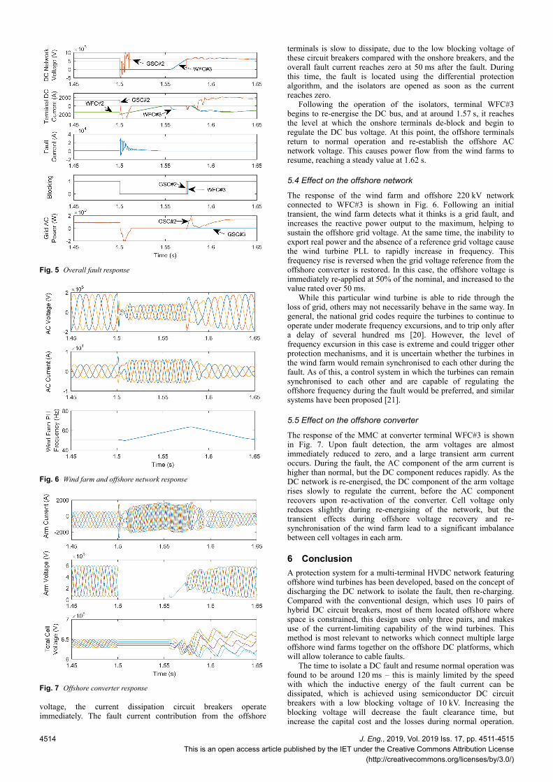
voltage, the current dissipation circuit breakers operateimmediately. The fault current contribution from the offshore
terminals is slow to dissipate, due to the low blocking voltage ofthese circuit breakers compared with the onshore breakers, and theoverall fault current reaches zero at 50 ms after the fault. Duringthis time, the fault is located using the differential protectionalgorithm, and the isolators are opened as soon as the currentreaches zero.
Following the operation of the isolators, terminal WFC#3begins to re-energise the DC bus, and at around 1.57 s, it reachesthe level at which the onshore terminals de-block and begin toregulate the DC bus voltage. At this point, the offshore terminalsreturn to normal operation and re-establish the offshore ACnetwork voltage. This causes power flow from the wind farms toresume, reaching a steady value at 1.62 s.
5.4 Effect on the offshore network
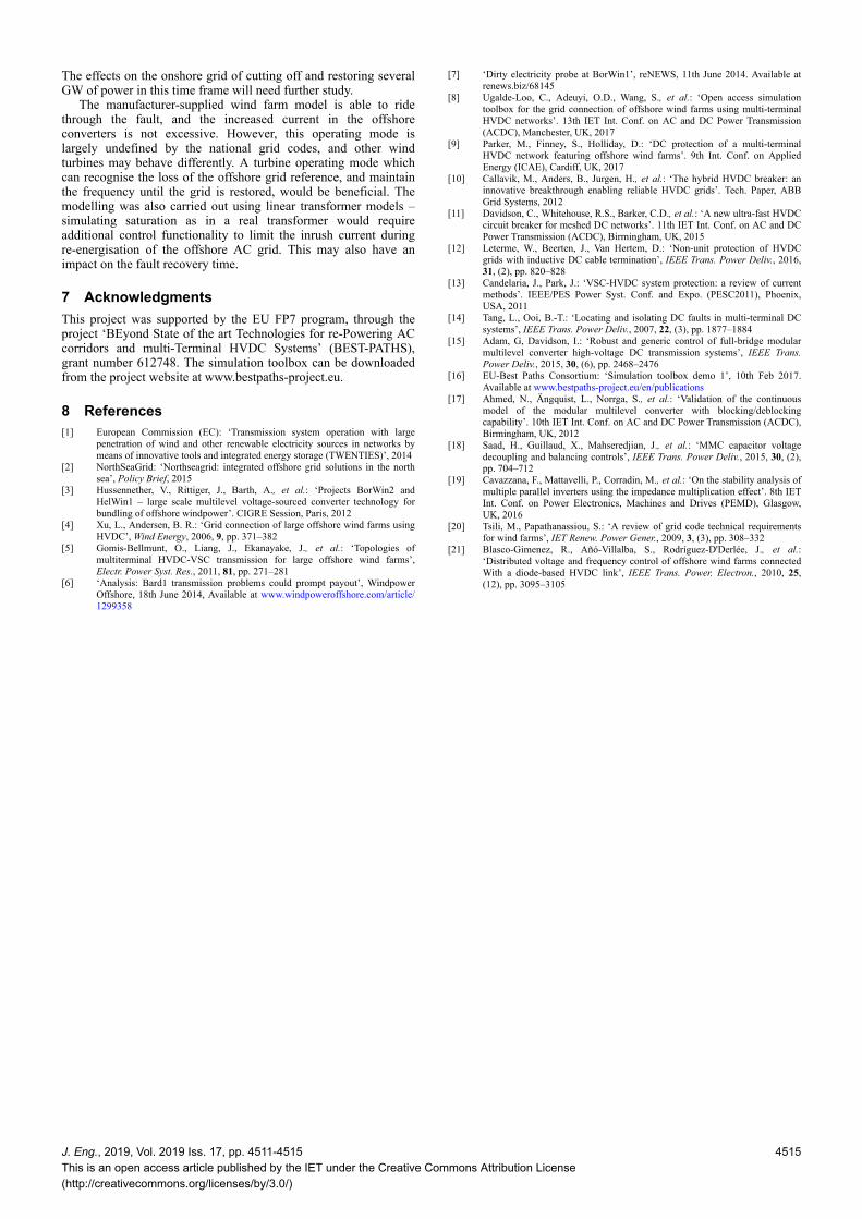
The response of the wind farm and offshore 220 kV networkconnected to WFC#3 is shown in Fig. 6. Following an initialtransient, the wind farm detects what it thinks is a grid fault, andincreases the reactive power output to the maximum, helping tosustain the offshore grid voltage. At the same time, the inability toexport real power and the absence of a reference grid voltage causethe wind turbine PLL to rapidly increase in frequency. Thisfrequency rise is reversed when the grid voltage reference from theoffshore converter is restored. In this case, the offshore voltage isimmediately re-applied at 50% of the nominal, and increased to thevalue rated over 50 ms.
While this particular wind turbine is able to ride through theloss of grid, others may not necessarily behave in the same way. Ingeneral, the national grid codes require the turbines to continue tooperate under moderate frequency excursions, and to trip only aftera delay of several hundred ms [20]. However, the level offrequency excursion in this case is extreme and could trigger otherprotection mechanisms, and it is uncertain whether the turbines inthe wind farm would remain synchronised to each other during thefault. As of this, a control system in which the turbines can remainsynchronised to each other and are capable of regulating theoffshore frequency during the fault would be preferred, and similarsystems have been proposed [21].
5.5 Effect on the offshore converter
The response of the MMC at converter terminal WFC#3 is shownin Fig. 7. Upon fault detection, the arm voltages are almostimmediately reduced to zero, and a large transient arm currentoccurs. During the fault, the AC component of the arm current ishigher than normal, but the DC component reduces rapidly. As theDC network is re-energised, the DC component of the arm voltagerises slowly to regulate the current, before the AC componentrecovers upon re-activation of the converter. Cell voltage onlyreduces slightly during re-energising of the network, but thetransient effects during offshore voltage recovery and re-synchronisation of the wind farm lead to a significant imbalancebetween cell voltages in each arm.
6 ConclusionA protection system for a multi-terminal HVDC network featuringoffshore wind turbines has been developed, based on the concept ofdischarging the DC network to isolate the fault, then re-charging.Compared with the conventional design, which uses 10 pairs ofhybrid DC circuit breakers, most of them located offshore wherespace is constrained, this design uses only three pairs, and makesuse of the current-limiting capability of the wind turbines. Thismethod is most relevant to networks which connect multiple largeoffshore wind farms together on the offshore DC platforms, whichwill allow tolerance to cable faults.
The time to isolate a DC fault and resume normal operation wasfound to be around 120 ms – this is mainly limited by the speedwith which the inductive energy of the fault current can bedissipated, which is achieved using semiconductor DC circuitbreakers with a low blocking voltage of 10 kV. Increasing theblocking voltage will decrease the fault clearance time, butincrease the capital cost and the losses during normal operation.
Fig. 5 Overall fault response
Fig. 6 Wind farm and offshore network response
Fig. 7 Offshore converter response
4514 J. Eng., 2019, Vol. 2019 Iss. 17, pp. 4511-4515This is an open access article published by the IET under the Creative Commons Attribution License
(http://creativecommons.org/licenses/by/3.0/)
The effects on the onshore grid of cutting off and restoring severalGW of power in this time frame will need further study.
The manufacturer-supplied wind farm model is able to ridethrough the fault, and the increased current in the offshoreconverters is not excessive. However, this operating mode islargely undefined by the national grid codes, and other windturbines may behave differently. A turbine operating mode whichcan recognise the loss of the offshore grid reference, and maintainthe frequency until the grid is restored, would be beneficial. Themodelling was also carried out using linear transformer models –simulating saturation as in a real transformer would requireadditional control functionality to limit the inrush current duringre-energisation of the offshore AC grid. This may also have animpact on the fault recovery time.
7 AcknowledgmentsThis project was supported by the EU FP7 program, through theproject ‘BEyond State of the art Technologies for re-Powering ACcorridors and multi-Terminal HVDC Systems’ (BEST-PATHS),grant number 612748. The simulation toolbox can be downloadedfrom the project website at www.bestpaths-project.eu.
8 References[1] European Commission (EC): ‘Transmission system operation with large
penetration of wind and other renewable electricity sources in networks bymeans of innovative tools and integrated energy storage (TWENTIES)’, 2014
[2] NorthSeaGrid: ‘Northseagrid: integrated offshore grid solutions in the northsea’, Policy Brief, 2015
[3] Hussennether, V., Rittiger, J., Barth, A., et al.: ‘Projects BorWin2 andHelWin1 – large scale multilevel voltage-sourced converter technology forbundling of offshore windpower’. CIGRE Session, Paris, 2012
[4] Xu, L., Andersen, B. R.: ‘Grid connection of large offshore wind farms usingHVDC’, Wind Energy, 2006, 9, pp. 371–382
[5] Gomis-Bellmunt, O., Liang, J., Ekanayake, J., et al.: ‘Topologies ofmultiterminal HVDC-VSC transmission for large offshore wind farms’,Electr. Power Syst. Res., 2011, 81, pp. 271–281
[6] ‘Analysis: Bard1 transmission problems could prompt payout’, WindpowerOffshore, 18th June 2014, Available at www.windpoweroffshore.com/article/1299358
[7] ‘Dirty electricity probe at BorWin1’, reNEWS, 11th June 2014. Available atrenews.biz/68145
[8] Ugalde-Loo, C., Adeuyi, O.D., Wang, S., et al.: ‘Open access simulationtoolbox for the grid connection of offshore wind farms using multi-terminalHVDC networks’. 13th IET Int. Conf. on AC and DC Power Transmission(ACDC), Manchester, UK, 2017
[9] Parker, M., Finney, S., Holliday, D.: ‘DC protection of a multi-terminalHVDC network featuring offshore wind farms’. 9th Int. Conf. on AppliedEnergy (ICAE), Cardiff, UK, 2017
[10] Callavik, M., Anders, B., Jurgen, H., et al.: ‘The hybrid HVDC breaker: aninnovative breakthrough enabling reliable HVDC grids’. Tech. Paper, ABBGrid Systems, 2012
[11] Davidson, C., Whitehouse, R.S., Barker, C.D., et al.: ‘A new ultra-fast HVDCcircuit breaker for meshed DC networks’. 11th IET Int. Conf. on AC and DCPower Transmission (ACDC), Birmingham, UK, 2015
[12] Leterme, W., Beerten, J., Van Hertem, D.: ‘Non-unit protection of HVDCgrids with inductive DC cable termination’, IEEE Trans. Power Deliv., 2016,31, (2), pp. 820–828
[13] Candelaria, J., Park, J.: ‘VSC-HVDC system protection: a review of currentmethods’. IEEE/PES Power Syst. Conf. and Expo. (PESC2011), Phoenix,USA, 2011
[14] Tang, L., Ooi, B.-T.: ‘Locating and isolating DC faults in multi-terminal DCsystems’, IEEE Trans. Power Deliv., 2007, 22, (3), pp. 1877–1884
[15] Adam, G, Davidson, I.: ‘Robust and generic control of full-bridge modularmultilevel converter high-voltage DC transmission systems’, IEEE Trans.Power Deliv., 2015, 30, (6), pp. 2468–2476
[16] EU-Best Paths Consortium: ‘Simulation toolbox demo 1’, 10th Feb 2017.Available at www.bestpaths-project.eu/en/publications
[17] Ahmed, N., Ängquist, L., Norrga, S., et al.: ‘Validation of the continuousmodel of the modular multilevel converter with blocking/deblockingcapability’. 10th IET Int. Conf. on AC and DC Power Transmission (ACDC),Birmingham, UK, 2012
[18] Saad, H., Guillaud, X., Mahseredjian, J., et al.: ‘MMC capacitor voltagedecoupling and balancing controls’, IEEE Trans. Power Deliv., 2015, 30, (2),pp. 704–712
[19] Cavazzana, F., Mattavelli, P., Corradin, M., et al.: ‘On the stability analysis ofmultiple parallel inverters using the impedance multiplication effect’. 8th IETInt. Conf. on Power Electronics, Machines and Drives (PEMD), Glasgow,UK, 2016
[20] Tsili, M., Papathanassiou, S.: ‘A review of grid code technical requirementsfor wind farms’, IET Renew. Power Gener., 2009, 3, (3), pp. 308–332
[21] Blasco-Gimenez, R., Añó-Villalba, S., Rodríguez-D'Derlée, J., et al.:‘Distributed voltage and frequency control of offshore wind farms connectedWith a diode-based HVDC link’, IEEE Trans. Power. Electron., 2010, 25,(12), pp. 3095–3105
J. Eng., 2019, Vol. 2019 Iss. 17, pp. 4511-4515This is an open access article published by the IET under the Creative Commons Attribution License(http://creativecommons.org/licenses/by/3.0/)
4515