TITAN PLATFORMS Offshore Wind Power Systems...
18
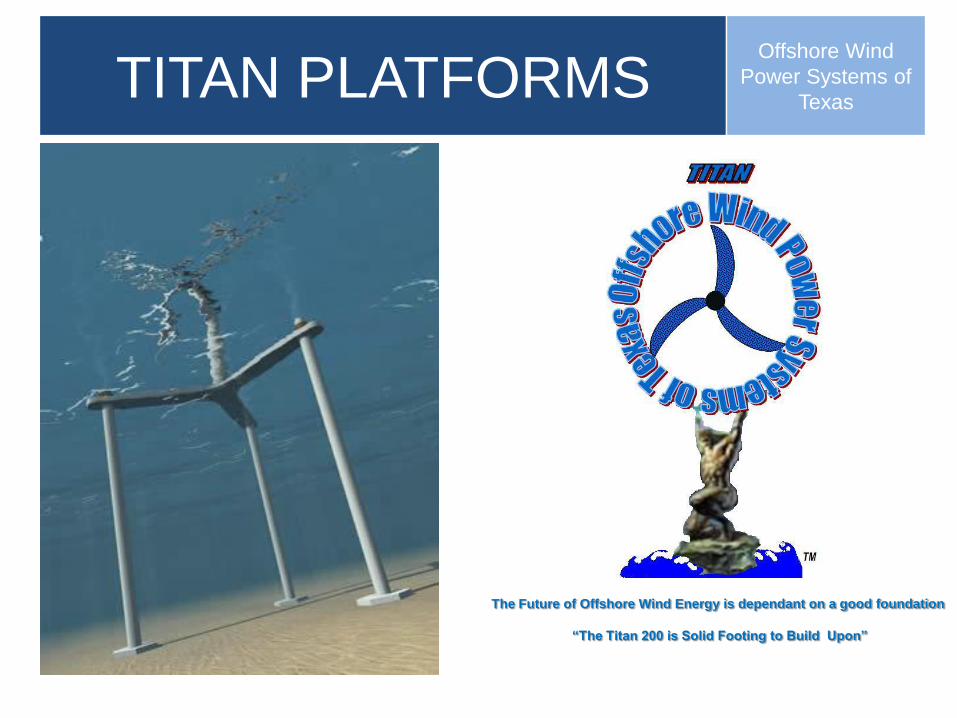
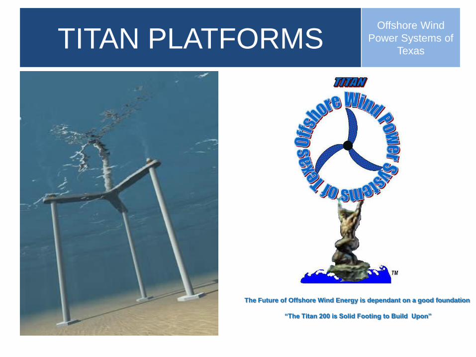
TITAN PLATFORMS Offshore Wind Power Systems of Texas The Future of Offshore Wind Energy is dependant on a good foundation “The Titan 200 is Solid Footing to Build Upon”
Transcript of TITAN PLATFORMS Offshore Wind Power Systems...
TITAN PLATFORMSOffshore Wind
Power Systems of
Texas
The Future of Offshore Wind Energy is dependant on a good foundation
“The Titan 200 is Solid Footing to Build Upon”
Project references – UK Round 3
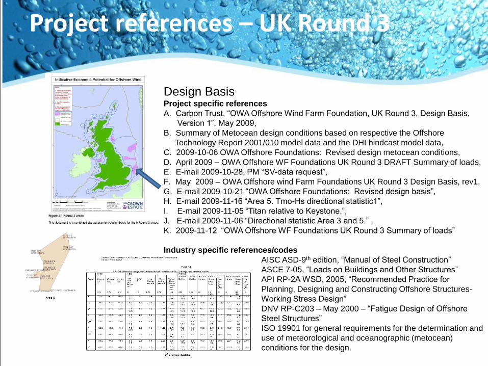
Design BasisProject specific references
A. Carbon Trust, “OWA Offshore Wind Farm Foundation, UK Round 3, Design Basis,
Version 1”, May 2009,
B. Summary of Metocean design conditions based on respective the Offshore
Technology Report 2001/010 model data and the DHI hindcast model data,
C. 2009-10-06 OWA Offshore Foundations: Revised design metocean conditions,
D. April 2009 – OWA Offshore WF Foundations UK Round 3 DRAFT Summary of loads,
E. E-mail 2009-10-28, PM “SV-data request”,
F. May 2009 – OWA Offshore wind Farm Foundations UK Round 3 Design Basis, rev1,
G. E-mail 2009-10-21 “OWA Offshore Foundations: Revised design basis”,
H. E-mail 2009-11-16 “Area 5. Tmo-Hs directional statistic1”,
I. E-mail 2009-11-05 “Titan relative to Keystone.”,
J. E-mail 2009-11-06 “Directional statistic Area 3 and 5.” ,
K. 2009-11-12 “OWA Offshore WF Foundations UK Round 3 Summary of loads”
Industry specific references/codes
AISC ASD-9th edition, “Manual of Steel Construction”
ASCE 7-05, “Loads on Buildings and Other Structures”
API RP-2A WSD, 2005, “Recommended Practice for
Planning, Designing and Constructing Offshore Structures-
Working Stress Design”
DNV RP-C203 – May 2000 – “Fatigue Design of Offshore
Steel Structures”
ISO 19901 for general requirements for the determination and
use of meteorological and oceanographic (metocean)
conditions for the design.
Structural Description
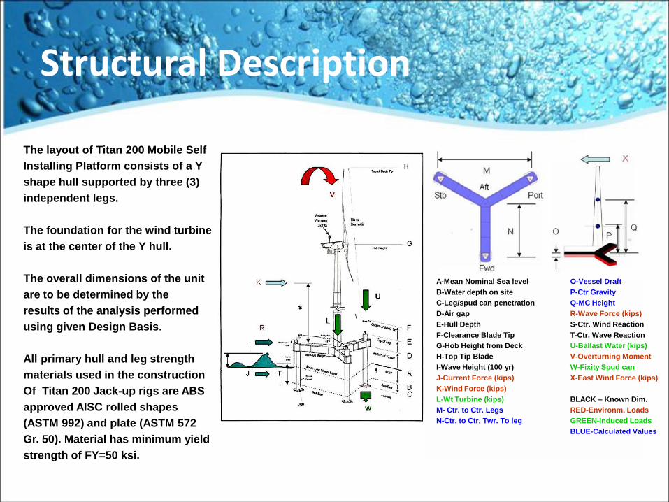
The layout of Titan 200 Mobile Self
Installing Platform consists of a Y
shape hull supported by three (3)
independent legs.
The foundation for the wind turbine
is at the center of the Y hull.
The overall dimensions of the unit
are to be determined by the
results of the analysis performed
using given Design Basis.
All primary hull and leg strength
materials used in the construction
Of Titan 200 Jack-up rigs are ABS
approved AISC rolled shapes
(ASTM 992) and plate (ASTM 572
Gr. 50). Material has minimum yield
strength of FY=50 ksi.
A-Mean Nominal Sea level O-Vessel Draft
B-Water depth on site P-Ctr Gravity
C-Leg/spud can penetration Q-MC Height
D-Air gap R-Wave Force (kips)
E-Hull Depth S-Ctr. Wind Reaction
F-Clearance Blade Tip T-Ctr. Wave Reaction
G-Hob Height from Deck U-Ballast Water (kips)
H-Top Tip Blade V-Overturning Moment
I-Wave Height (100 yr) W-Fixity Spud can
J-Current Force (kips) X-East Wind Force (kips)
K-Wind Force (kips)
L-Wt Turbine (kips) BLACK – Known Dim.
M- Ctr. to Ctr. Legs RED-Environm. Loads
N-Ctr. to Ctr. Twr. To leg GREEN-Induced Loads
BLUE-Calculated Values
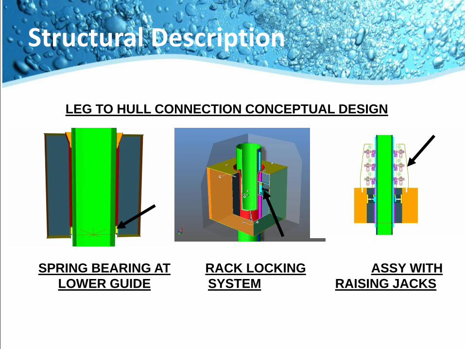
Structural Description
LEG TO HULL CONNECTION CONCEPTUAL DESIGN
SPRING BEARING AT
LOWER GUIDE
RACK LOCKING
SYSTEM
ASSY WITH
RAISING JACKS
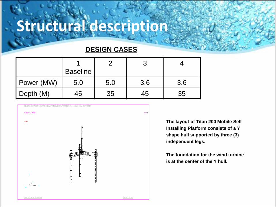
Structural description
The layout of Titan 200 Mobile Self
Installing Platform consists of a Y
shape hull supported by three (3)
independent legs.
The foundation for the wind turbine
is at the center of the Y hull.
DESIGN CASES
1
Baseline
2 3 4
Power (MW) 5.0 5.0 3.6 3.6
Depth (M) 45 35 45 35
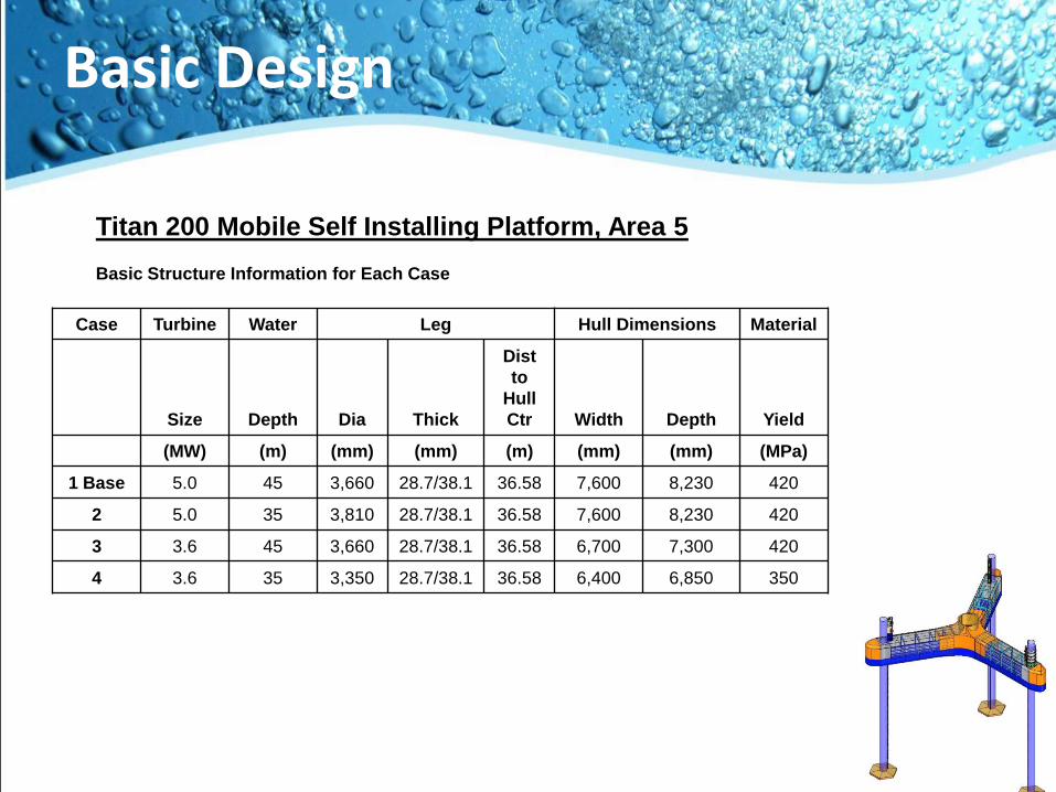
Basic Design
Titan 200 Mobile Self Installing Platform, Area 5
Basic Structure Information for Each Case
Case Turbine Water Leg Hull Dimensions Material
Size Depth Dia Thick
Dist
to
Hull
Ctr Width Depth Yield
(MW) (m) (mm) (mm) (m) (mm) (mm) (MPa)
1 Base 5.0 45 3,660 28.7/38.1 36.58 7,600 8,230 420
2 5.0 35 3,810 28.7/38.1 36.58 7,600 8,230 420
3 3.6 45 3,660 28.7/38.1 36.58 6,700 7,300 420
4 3.6 35 3,350 28.7/38.1 36.58 6,400 6,850 350
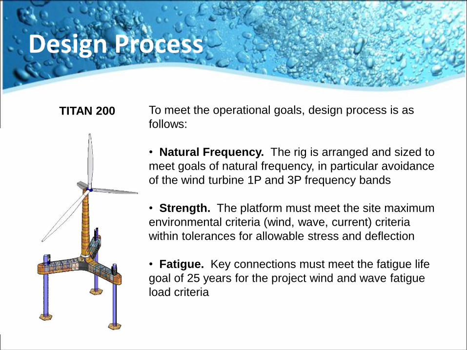
Design Process
To meet the operational goals, design process is as
follows:
• Natural Frequency. The rig is arranged and sized to
meet goals of natural frequency, in particular avoidance
of the wind turbine 1P and 3P frequency bands
• Strength. The platform must meet the site maximum
environmental criteria (wind, wave, current) criteria
within tolerances for allowable stress and deflection
• Fatigue. Key connections must meet the fatigue life
goal of 25 years for the project wind and wave fatigue
load criteria
TITAN 200
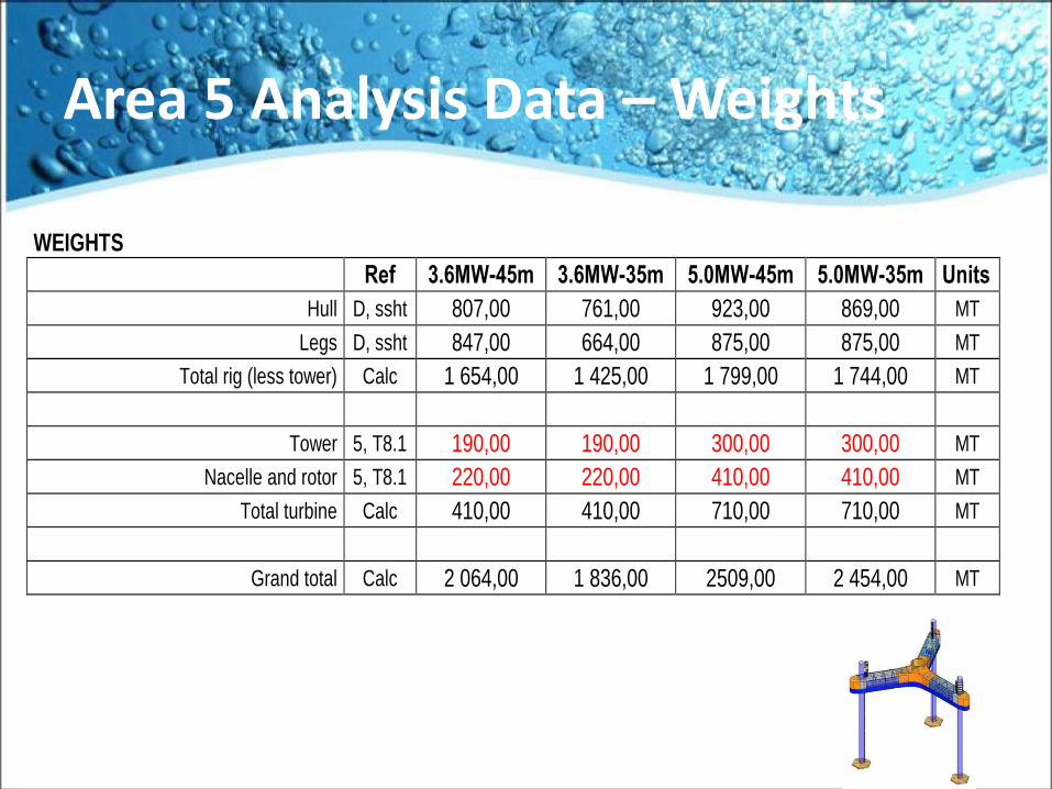
Area 5 Analysis Data – Weights
WEIGHTS Ref 3.6MW-45m 3.6MW-35m 5.0MW-45m 5.0MW-35m Units
Hull D, ssht 807,00 761,00 923,00 869,00 MT
Legs D, ssht 847,00 664,00 875,00 875,00 MT
Total rig (less tower) Calc 1 654,00 1 425,00 1 799,00 1 744,00 MT
Tower 5, T8.1 190,00 190,00 300,00 300,00 MT
Nacelle and rotor 5, T8.1 220,00 220,00 410,00 410,00 MT
Total turbine Calc 410,00 410,00 710,00 710,00 MT
Grand total Calc 2 064,00 1 836,00 2509,00 2 454,00 MT
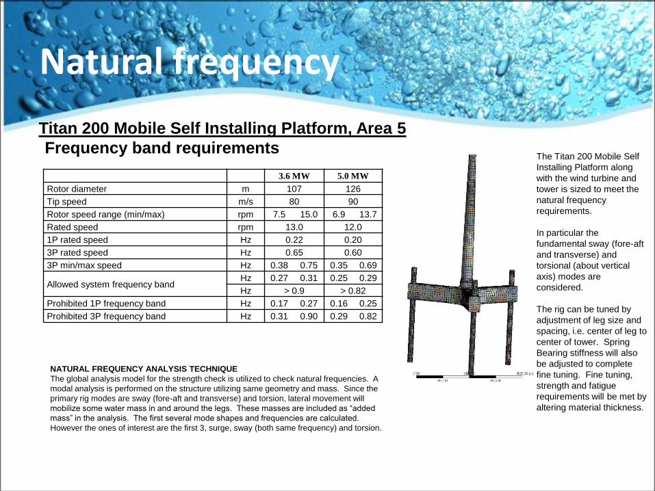
Natural frequency
Titan 200 Mobile Self Installing Platform, Area 5
Frequency band requirements
3.6 MW 5.0 MW
Rotor diameter m 107 126
Tip speed m/s 80 90
Rotor speed range (min/max) rpm 7.5 15.0 6.9 13.7
Rated speed rpm 13.0 12.0
1P rated speed Hz 0.22 0.20
3P rated speed Hz 0.65 0.60
3P min/max speed Hz 0.38 0.75 0.35 0.69
Allowed system frequency bandHz 0.27 0.31 0.25 0.29
Hz > 0.9 > 0.82
Prohibited 1P frequency band Hz 0.17 0.27 0.16 0.25
Prohibited 3P frequency band Hz 0.31 0.90 0.29 0.82
The Titan 200 Mobile Self
Installing Platform along
with the wind turbine and
tower is sized to meet the
natural frequency
requirements.
In particular the
fundamental sway (fore-aft
and transverse) and
torsional (about vertical
axis) modes are
considered.
The rig can be tuned by
adjustment of leg size and
spacing, i.e. center of leg to
center of tower. Spring
Bearing stiffness will also
be adjusted to complete
fine tuning. Fine tuning,
strength and fatigue
requirements will be met by
altering material thickness.
NATURAL FREQUENCY ANALYSIS TECHNIQUE
The global analysis model for the strength check is utilized to check natural frequencies. A
modal analysis is performed on the structure utilizing same geometry and mass. Since the
primary rig modes are sway (fore-aft and transverse) and torsion, lateral movement will
mobilize some water mass in and around the legs. These masses are included as “added
mass” in the analysis. The first several mode shapes and frequencies are calculated.
However the ones of interest are the first 3, surge, sway (both same frequency) and torsion.
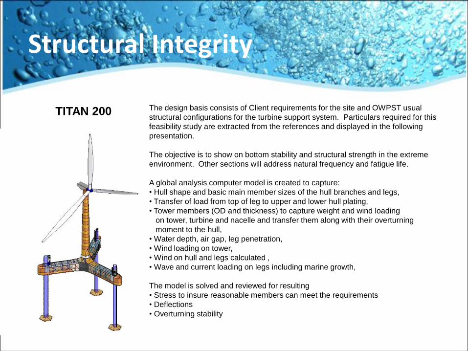
Structural Integrity
The design basis consists of Client requirements for the site and OWPST usual
structural configurations for the turbine support system. Particulars required for this
feasibility study are extracted from the references and displayed in the following
presentation.
The objective is to show on bottom stability and structural strength in the extreme
environment. Other sections will address natural frequency and fatigue life.
A global analysis computer model is created to capture:
• Hull shape and basic main member sizes of the hull branches and legs,
• Transfer of load from top of leg to upper and lower hull plating,
• Tower members (OD and thickness) to capture weight and wind loading
on tower, turbine and nacelle and transfer them along with their overturning
moment to the hull,
• Water depth, air gap, leg penetration,
• Wind loading on tower,
• Wind on hull and legs calculated ,
• Wave and current loading on legs including marine growth,
The model is solved and reviewed for resulting
• Stress to insure reasonable members can meet the requirements
• Deflections
• Overturning stability
TITAN 200
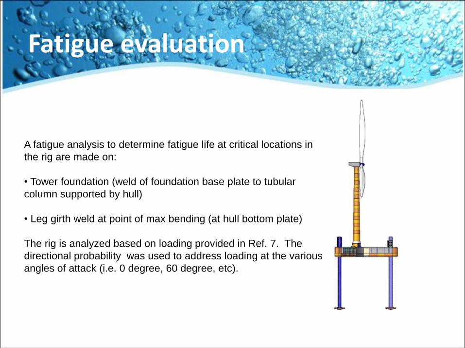
Fatigue evaluation
A fatigue analysis to determine fatigue life at critical locations in
the rig are made on:
• Tower foundation (weld of foundation base plate to tubular
column supported by hull)
• Leg girth weld at point of max bending (at hull bottom plate)
The rig is analyzed based on loading provided in Ref. 7. The
directional probability was used to address loading at the various
angles of attack (i.e. 0 degree, 60 degree, etc).
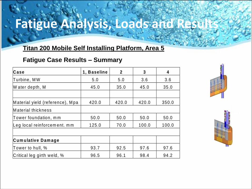
Fatigue Analysis, Loads and Results
Titan 200 Mobile Self Installing Platform, Area 5
Fatigue Case Results – Summary
C ase 1, B aseline 2 3 4
Turbine, M W 5.0 5.0 3.6 3.6
W ater depth, M 45.0 35.0 45.0 35.0
M ateria l yie ld (reference), M pa 420.0 420.0 420.0 350.0
M ateria l th ickness
Tower foundation, m m 50.0 50.0 50.0 50.0
Leg local re inforcem ent. m m 125.0 70.0 100.0 100.0
C um ulative D am age
Tower to hull, % 93.7 92.5 97.6 97.6
C ritica l leg g irth weld, % 96.5 96.1 98.4 94.2
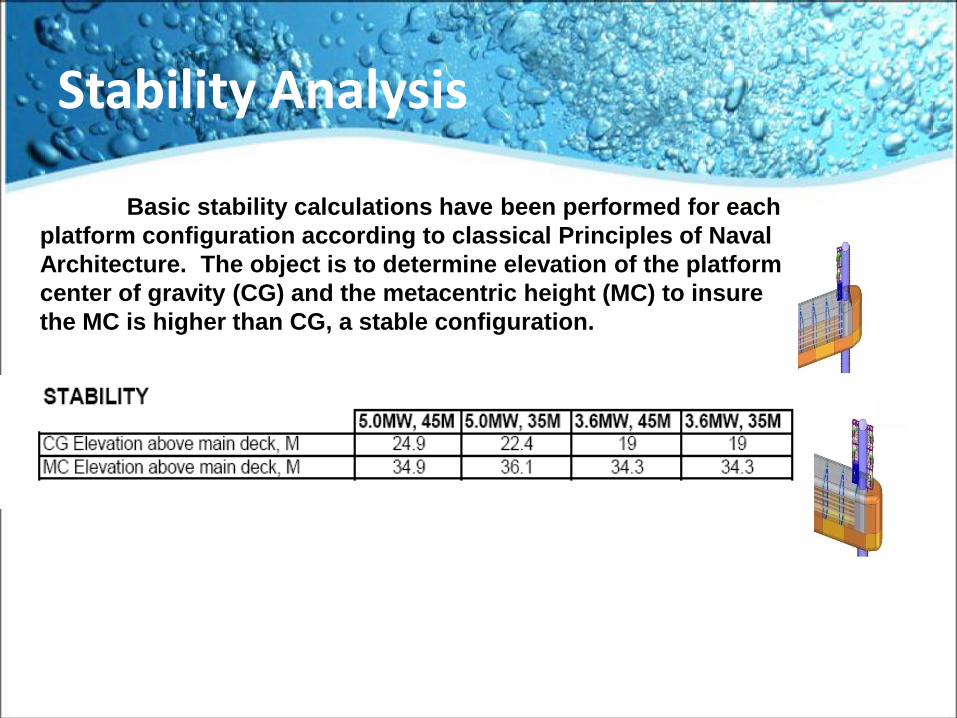
Stability Analysis
Basic stability calculations have been performed for each
platform configuration according to classical Principles of Naval
Architecture. The object is to determine elevation of the platform
center of gravity (CG) and the metacentric height (MC) to insure
the MC is higher than CG, a stable configuration.
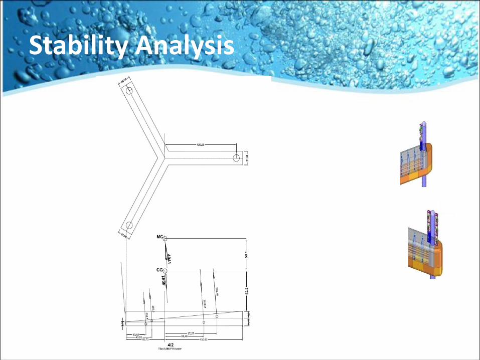
Stability Analysis
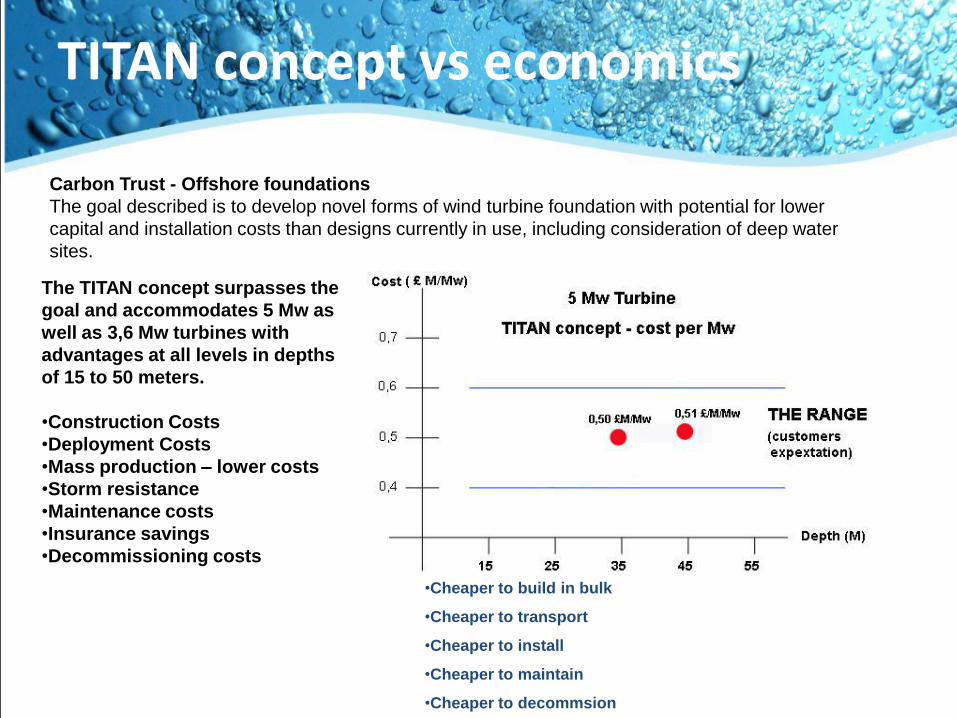
TITAN concept vs economics
The TITAN concept surpasses the
goal and accommodates 5 Mw as
well as 3,6 Mw turbines with
advantages at all levels in depths
of 15 to 50 meters.
•Construction Costs
•Deployment Costs
•Mass production – lower costs
•Storm resistance
•Maintenance costs
•Insurance savings
•Decommissioning costs
Carbon Trust - Offshore foundations
The goal described is to develop novel forms of wind turbine foundation with potential for lower
capital and installation costs than designs currently in use, including consideration of deep water
sites.
•Cheaper to build in bulk
•Cheaper to transport
•Cheaper to install
•Cheaper to maintain
•Cheaper to decommsion

Experienced Engineers
Designed and analyzed by professionals Experience
The Titan 200 provides the international offshore wind
industry with proven versatile tool for the development
and production of power in most world regions
economically.
The TITAN 200 is according to classification by the
American Bureau of Shipping and built in accordance with
the latest MODU Code established by the
IMO Resolution A.649(16).
When required by the customer, the unit can be
manufactured to meet the requirements of the United States
Coast guard, The Netherlands Department of Mines or other
regulatory bodies.
We have been providing this same service to our clients
for over 30 years on a World Wide bases meeting the most
stringent design requirements, we design, certify,
manufacture and service
Why Chose the TITAN
Issue Titan 200 Highlights
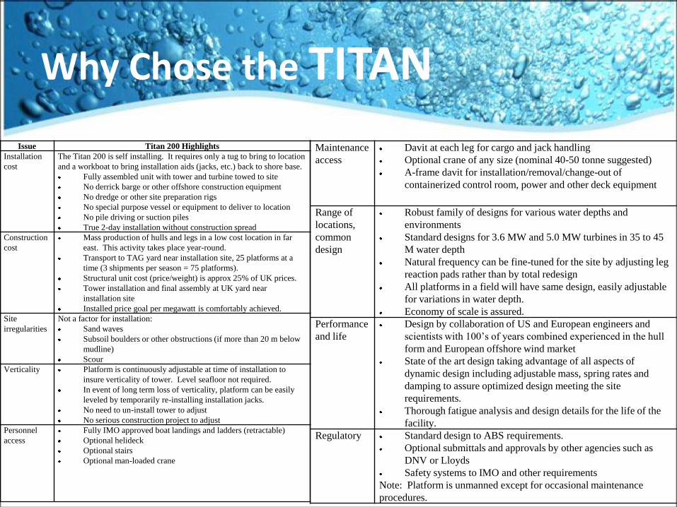
Installation
cost
The Titan 200 is self installing. It requires only a tug to bring to location
and a workboat to bring installation aids (jacks, etc.) back to shore base.
Fully assembled unit with tower and turbine towed to site
No derrick barge or other offshore construction equipment
No dredge or other site preparation rigs
No special purpose vessel or equipment to deliver to location
No pile driving or suction piles
True 2-day installation without construction spread
Construction
cost
Mass production of hulls and legs in a low cost location in far
east. This activity takes place year-round.
Transport to TAG yard near installation site, 25 platforms at a
time (3 shipments per season = 75 platforms).
Structural unit cost (price/weight) is approx 25% of UK prices.
Tower installation and final assembly at UK yard near
installation site
Installed price goal per megawatt is comfortably achieved.
Site
irregularities
Not a factor for installation:
Sand waves
Subsoil boulders or other obstructions (if more than 20 m below
mudline)
Scour
Verticality Platform is continuously adjustable at time of installation to
insure verticality of tower. Level seafloor not required.
In event of long term loss of verticality, platform can be easily
leveled by temporarily re-installing installation jacks.
No need to un-install tower to adjust
No serious construction project to adjust
Personnel
access
Fully IMO approved boat landings and ladders (retractable)
Optional helideck
Optional stairs
Optional man-loaded crane
Maintenance
access
Davit at each leg for cargo and jack handling
Optional crane of any size (nominal 40-50 tonne suggested)
A-frame davit for installation/removal/change-out of
containerized control room, power and other deck equipment
Range of
locations,
common
design
Robust family of designs for various water depths and
environments
Standard designs for 3.6 MW and 5.0 MW turbines in 35 to 45
M water depth
Natural frequency can be fine-tuned for the site by adjusting leg
reaction pads rather than by total redesign
All platforms in a field will have same design, easily adjustable
for variations in water depth.
Economy of scale is assured.
Performance
and life
Design by collaboration of US and European engineers and
scientists with 100’s of years combined experienced in the hull
form and European offshore wind market
State of the art design taking advantage of all aspects of
dynamic design including adjustable mass, spring rates and
damping to assure optimized design meeting the site
requirements.
Thorough fatigue analysis and design details for the life of the
facility.
Regulatory Standard design to ABS requirements.
Optional submittals and approvals by other agencies such as
DNV or Lloyds
Safety systems to IMO and other requirements
Note: Platform is unmanned except for occasional maintenance
procedures.
TITAN PLATFORMSOffshore Wind
Power Systems of
Texas
The Future of Offshore Wind Energy is dependant on a good foundation
“The Titan 200 is Solid Footing to Build Upon”