NET METERING SUB-CODE - Energy Commissionenergycom.gov.gh/files/Net Metering Sub-Code, 2015.pdfNET...
24
JANUARY 2015 NET METERING SUB-CODE for Connecting Renewable Energy Generating Systems to the Distribution Network in Ghana
Transcript of NET METERING SUB-CODE - Energy Commissionenergycom.gov.gh/files/Net Metering Sub-Code, 2015.pdfNET...
Page 2
JANUARY 2015
NET METERING SUB-CODE
for Connecting Renewable Energy Generating Systems
to the Distribution Network in Ghana
1
Table of Contents
PART A: BACKGROUND ....................................................................................................................... 1
1 Introduction .................................................................................................................................. 1
1.1 Objective ........................................................................................................................................ 1
1.2 Status ............................................................................................................................................. 1
2 Terms, Definitions and Abbreviations ....................................................................................... 2
2.1 Terms and Definitions .............................................................................................................. 2
2.2 Abbreviations ........................................................................................................................... 5
PART B: GUIDELINES FOR NET METERING ...................................................................................... 6
Connection Agreement ......................................................................................................................... 6
Application for Connection of Renewable Energy Generation to Distribution Network ............... 6
Connection of Bi-Directional Supply ................................................................................................... 7
Precaution Against Atmospheric Electricity ...................................................................................... 8
Illegal Connections ................................................................................................................................ 8
Metering .................................................................................................................................................. 8
Compensation and Billing .................................................................................................................... 9
Disconnection of Supply of Electricity .............................................................................................. 10
Termination .......................................................................................................................................... 10
Assignment .......................................................................................................................................... 10
Complaints and Dispute Resolution .................................................................................................. 10
PART C: TECHNICAL CONNECTION ................................................................................................. 11
3 Utility Compatibility .................................................................................................................... 11
3.1 General Guidelines ................................................................................................................ 11
3.2 Frequency Range of Operation ............................................................................................. 11
3.3 Voltage Range of Operation .................................................................................................. 11
3.4 Power Factor ......................................................................................................................... 12
3.5 Response to Network Disturbance ........................................................................................ 12
3.5.1 Maximum fault current ................................................................................................ 12
3.5.2 Voltage sags/Voltage spikes/Abnormal voltage range of operation ...................... 12
3.6 Power Quality ........................................................................................................................ 12
3.6.1 DC current injection .................................................................................................... 12
3.6.2 Rapid voltage changes ............................................................................................... 12
3.6.3 Voltage unbalance ....................................................................................................... 12
3.6.4 Flicker ........................................................................................................................... 12
3.6.5 Harmonics .................................................................................................................... 13
4 Safety and Protection ................................................................................................................ 15
4.1 System Safety and Protection ............................................................................................... 15
4.1.1 General ......................................................................................................................... 15
4.1.2 Synchronization ........................................................................................................... 15
4.1.3 Protection and control devices .................................................................................. 15
NET METERING SUB-CODE
ii
4.1.4 Reclosing ...................................................................................................................... 15
4.1.5 Loss of utility voltage (Islanding) .............................................................................. 15
4.1.6 Earthing ........................................................................................................................ 15
4.1.7 Over/under voltage ...................................................................................................... 16
4.1.8 Over/under frequency ................................................................................................. 17
4.1.9 Short circuit protection ............................................................................................... 17
4.2 Safety and Protection ............................................................................................................ 17
4.2.1 General ......................................................................................................................... 17
4.2.2 Labelling ....................................................................................................................... 17
4.2.3 Emergency shutdown ................................................................................................. 17
5 Metering ...................................................................................................................................... 18
5.1 Net Metering .......................................................................................................................... 18
5.2 Type of Meter......................................................................................................................... 18
6 Testing and Commissioning ..................................................................................................... 19
6.1 General .................................................................................................................................. 19
6.2 Inverter certification ............................................................................................................... 19
7 Annexes ...................................................................................................................................... 20
7.1 Annex A - Connection Example............................................................................................. 20
7.2 Annex B – Solar Supply Isolator in Switchboard ................................................................... 21
1
PART A: BACKGROUND
1 Introduction
This Net Metering Sub-Code in accordance with provisions of the Renewable Energy Act 2011, Act 832 which provides for the development, management, utilisation, sustainability and adequate supply of renewable energy generation of heat and power and for related matters. Net Metering is a billing related mechanism designed to encourage electricity consumers to supplement their purchase of electricity with grid-connected renewable energy self-generation. Thus the customer becomes a Customer-generator. Under the net metering billing mechanism, renewable energy generation facility owners are credited for electricity the facility supplies to the grid, and this credit is set off against electricity purchased from the Distribution Utility. Net metering is designed for applications where the renewable energy generation is not being used as a back-up to the main source of power supply. Instead, the excess energy is supplied to the Distribution Utility, on the assumption that the amount of energy supplied to the grid will not exceed the amount purchased over an annual tracking period. The motivation of the renewable energy generation facility owner in net metering is generally power cost reduction or climate change mitigation. Net metering is not designed to be an income generating mechanism for the renewable energy generation facility owner. An applicant seeking connection to the low-voltage secondary distribution network, that is nominal voltage <1kV, should comply with the ‘Net Metering Sub-Code, 2015’ and all applicable articles of the National Electricity Distribution Code.
This document is in line with the Renewable Energy Sub-Code (Distribution), National Electricity
Distribution Code, National Electricity Grid Code, applicable IEC and IEEE standards and other
international best practices.
1.1 Objective
This Sub-Code provides guidelines and technical connection conditions for the inter-connection of
renewable energy generating facility to the low voltage distribution network under net metering scheme.
1.2 Status
This Sub-Code constitutes an Addendum to the National Electricity Distribution Code.
NET METERING SUB-CODE
2
2 Terms, Definitions and Abbreviations
2.1 Terms and Definitions
In this Sub-Code, unless the context otherwise requires,
Bi-directional meter
Meter that measures the active energy (Wh) flow in both directions (import and export) and
displays both imported and exported energy in separate registers.
NOTE: Active energy flow in a meter is measured in watt-hours (Wh).
Calendar Year
The period from 1st January to 31st December of the same year.
Connection Agreement
An agreement between the Customer-generator and a Distribution Company that sets out the
rights, obligations and liabilities of both parties.
Customer-generator
Any Customer of a Distribution Utility that generates electricity on the Customer’s side of the
billing meter with renewable energy generation system that is primarily intended to offset part
or all of the Customer’s electricity consumption.
Disconnection switching unit
Switching unit that disconnects the small scale embedded generator operating in parallel with
the utility network from the network in response to an out-of-bounds condition.
Distribution Network
In relation to a Distribution Utility, means a system of electric lines and associated equipment
(generally at nominal voltage levels of 36 kV or below), which that Distribution Utility is licensed
to use to distribute electricity for supply under its distribution licence excluding public lighting
assets.
Distribution Utility
A person or entity licensed under the Energy Commission Act 1997 (Act 541) to distribute and
sell electricity without discrimination to consumers in an area or zone designated by the Energy
Commission Board.
Emergency
An emergency due to the actual or imminent occurrence of an event which in any way endangers
or threatens to endanger the safety or health of any person or which destroys or damages, or
threatens to destroy or damage any property.
Flicker
Voltage fluctuations producing the subjective impression of fluctuations in the luminance via the
functional chain electric lamp-eye-brain.
Grid-connected renewable energy system
A power system energised by a renewable energy source which is connected to the distribution
network.
NET METERING SUB-CODE
3
Island
State in which a portion of the utility or customer’s network containing load and generation,
continues to operate in isolation from the rest of the grid.
Minister
The Minister responsible for Energy.
Net Metering
A methodology under which electrical energy generated by a Customer-generator and delivered
to the distribution facilities as measured by an appropriate device to offset electric energy supply
by the Distribution Utility to the Customer-generator during the applicable billing period.
NOTE: Net Metering is not designed to be an income generating mechanism and the Supplier
will not have to make monetary payments to Customer-generators.
Net-Metered Generating Unit
Rooftop PV system with inverter that is grid tied through a connection to the low voltage
distribution network under the Net Metering scheme.
Photovoltaic PV
Method of generation of d.c. electricity by a device when exposed to solar radiation.
Point of Generator Connection (PGC)
The circuit-breaker and associated ancillary equipment (instrument transformers, protection,
isolators) that connects a generator to any electrical network. Where more than one such circuit-
breaker exists, the PGC shall be the circuit-breaker electrically closest to the generator,
alternatively, POC (Point of Connection).
Point of Utility Connection (PUC)
Interconnection between the small scale embedded generator and the utility distribution
network, referring to the node on the utility network electrically closest to a particular small scale
embedded generator’s installation, alternatively PCC (Point of Common coupling).
Power factor
Ratio of the r.m.s. value of the active power to the apparent power, measured over the same
integrating period.
NOTE Active power is measured in kilowatts and apparent power in kilovolt-amperes.
Prevention of islanding
Small scale embedded generator’s ability to detect loss-of-grid and prevent the condition of
unintended islanding.
Renewable energy generation facility
An electrical energy generation system that uses renewable energy resources as defined in the
Renewable Energy Act, 2011 (Act 832), with an inverter facility that is electrically connected
directly to a low voltage distribution network and for which the total output of the facility is
distributed and utilised locally without any requirement for use of the national interconnected
transmission system.
NET METERING SUB-CODE
4
Safety disconnect
Independent control system that monitors the utility network conditions and disconnects the a.c.
output of the small scale embedded generator from the network for out-of-bounds conditions.
Supplier
A person licensed under the Act 541 to distribute and sell electricity without discrimination to
consumers in an area or zone designated by the Energy Commission Board.
Simple separation
Galvanic separation between circuits or between a circuit and earth by means of basic
insulation.
Static power converter
Power electronic device that converts variable d.c. or a.c. to grid compatible a.c. either
synchronously (able to operate in stand-alone mode) or asynchronously (requires utility
interconnection).
Small scale embedded generator
One or more energy generation sources rated up to 100 kVA, that includes the energy
conversion device (devices), the static power converter (converters), if applicable, and the
control and protection gear within a customer’s network that operate in synchronism with the
utility’s supply.
NOTE 1 Examples of energy conversion devices are photovoltaic modules, fuel cells, induction
generators or synchronous generators.
Synchronization
the process of connecting two previously separated alternating current apparatuses after
matching frequency ,voltage, phase angles like paralleling a generator to the electric system;
Uni-directional meter
A meter that measures the active energy flow in one direction only and ignores the active energy
flow in the reverse direction.
NOTE Active energy is measured in watt-hours (Wh).
Utility interface
Interconnection between the small scale renewable generation system and the utility distribution
network, the PUC or point of common coupling.
NET METERING SUB-CODE
5
2.2 Abbreviations
a.c.: alternating current
CB: circuit-breaker
DB: distribution board
d.c.: direct current
EA: Electricity Association
E/L: earth leakage
EG: Embedded Generator
FIT: Feed-in Tariff
LDC: Local Distribution Company
NITS: National Interconnected Transmission System
PGC: Point of Generator Connection
PUC: Point of Utility Connection
PV: Photovoltaic
r.m.s.: root mean square
SSEG Small Scale Embedded Generator
TDD: Total Demand Distortion
NET METERING SUB-CODE
6
PART B: GUIDELINES FOR NET METERING
Connection Agreement
1. A Customer-generator and the Distribution Utility shall enter into a Connection Agreement that is consistent with this Code.
2. A Customer-generator who seeks a connection shall be subject to all applicable laws and bound by the terms and conditions of the Distribution Utility’s Conditions of Service as amended. These Conditions of Service shall be filed with the Energy Commission and made available on request.
3. The total generating capacity of a net-metered facility shall be limited to 200kW per installation.
Application for Connection of Renewable Energy Generation to Distribution Network
4. An applicant in applying for connection to the distribution network shall
a) ensure that the design and installation of the renewable energy generation facility is in accordance with the specifications of the Distribution Utility to guarantee the safety and security of both the renewable energy generation facility and the distribution network.
b) ensure that the electrical installations at the premises to be connected are carried out
by a electrician duly certified under Electrical Wiring Regulations, 2011 (LI 2008);
c) obtain from the electrician a duly signed and sealed Installation Completion Certificate;
d) prior to the connection of the renewable energy generation facility to the distribution
network, install an isolation device and a protection device approved by the Distribution Utility, and agree to allow the Distribution Utility’s staff access to and observe the operation of these devices as required for the maintenance of the distribution network; and
e) ensure the automatic disconnection of the renewable energy generation facility from the distribution network, as per the generator protective relay settings specified in the Connection Agreement with the Distribution Utility, in the event of a power outage on the distribution network or any abnormal operation of the distribution network.
5. The Distribution Utility shall provide the application form for a distributed generation connection and the form shall state the terms and conditions in English.
6. The terms and conditions shall include provisions that the applicant
a) informs the Distribution Utility of the capacity of the renewable energy generation facility
to be installed, estimated load and expected energy consumption at the applicant’s
premises;
b) agrees to pay the requisite fee including the capital contribution where necessary and
an advance deposit for connection and net metering equipment;
c) permits reasonable access at reasonable times and adequate protection for the
Distribution Utility’s agent during meter reading, fault rectification, disconnection and
other lawful activities connected with the supply at the applicant’s premises;
NET METERING SUB-CODE
7
d) provides an accurate contact address for the delivery of electricity bills; and
e) is not to:
i) connect supply which is not passed through a meter, and
ii) tamper with a meter or any ancillary equipment associated with the supply.
7. The applicant shall attach the Installation Completion Certificate to the application form for a new connection and submit the application to the Distribution Utility.
8. On receipt of an application form, the Distribution Utility shall first provide the estimate of materials and charges for the connection within five (5) working days.
9. Where the applicant pays the required cost of materials and charges, the Distribution Utility shall install a bi-directional meter and other necessary equipment required for bi-directional flow of electricity within five (5) working days.
10. The Distribution Utility shall make the net metering application form available at its website.
Connection of Bi-Directional Supply
11. A Distribution Utility shall on receipt of an application provide, install and maintain the necessary equipment required for bi-directional flow of electricity and sale of electricity to a Customer-generator.
12. The Distribution Utility shall provide a non-discriminatory bi-directional electricity supply service to all Customer-generators.
13. The bi-directional supply shall be connected through an appropriate service connection and protective device that is in accordance with the applicable standards.
14. A Customer-generator or an applicant shall:
a) ensure that the electrical installation is safe for the bi-directional supply of electricity;
b) provide safe and reasonable access to customer’s premises for the Distribution Utility
to undertake work related to the bi-directional flow of electricity; and
c) keep vegetation at the premises clear from the Distribution Utility’s medium and low
voltage distribution network.
15. Where a Customer-generator or an applicant for a bi-directional connection fails to comply with any of the provisions of Clause 14, the Distribution Utility may:
a) in the case of a Customer-generator already connected to the distribution network,
disconnect bi-directional electricity supply to the Customer; or
b) in the case of an applicant for a new connection, refuse to connect the applicant to the
distribution network.
16. When a Customer-generator or an applicant complies with Clause 14, the Distribution Utility shall reconnect or connect bi-directional supply of electricity as the case may be.
17. A Customer-generator shall not:
NET METERING SUB-CODE
8
a) use any electrical equipment or appliance that shall interfere with, cause damage to or
degrade the quality of electricity supply to other Customers on the distribution network;
b) increase the contracted electricity demand without the consent of the Distribution Utility;
or
c) intentionally interfere or knowingly allow interference with the distribution network,
meter or any equipment that is used for the supply of electricity to it.
18. The Customer-generator shall perform regular scheduled maintenance to the renewable energy generation facility as outlined by the manufacturer in order to ensure that connection devices, protection systems, and control systems are maintained in good working condition and in compliance with all applicable laws.
19. The maintenance and operation of the renewable energy generation facility shall be conducted in a manner that ensures the safety and security of both the renewable energy generation facility and the distribution network.
20. In the event that the Distribution Utility determines that the renewable energy generation facility causes damage that adversely affect other distribution network Customers or the Distribution Utility’s assets, the facility shall be disconnected immediately from the distribution network upon direction from the Distribution Utility and the Customer-generator shall correct the problem at its expense.
Precaution Against Atmospheric Electricity
21. A Customer-generator shall, if the Distribution Utility so requires, provide the means for averting any damage to the installation by atmospheric electricity as the Distribution Utility may determine.
Illegal Connections
22. An electricity supply to any premises made contrary to Clauses 4 - 9 is illegal.
23. An illegal connection made under Clause 22 shall be disconnected in accordance with the Public Utilities (Termination of Service) Regulations, 1999 (L.I. 1651).
24. Without prejudice to any other enactment, where it is established that an illegal connection resulted in damage to the Distribution Utility’s or a third party’s property, the person who made the illegal connection shall be liable for the cost of repairs or replacement of the damaged property.
Metering
25. An applicant must provide a suitable location at the applicant‘s premises for the installation of and easy access to, the Distribution Utility’s bi-directional meter.
26. The applicant shall bear the cost of the bi-directional meter.
27. The Distribution Utility shall
a) provide, install and maintain the bi-directional meter that will measure and record the
amount of electricity supplied to the Customer-generator and supplied to the Distribution
NET METERING SUB-CODE
9
Utility system by the Customer-generator within specified accuracy limits of that meter’s
class;
b) affix the bi-directional meter to the Customer-generator’s premises or such other place,
and position it in such a way as to allow for easy access;
c) ensure that the bi-directional meter is robust and easy to read by the Customer-
generator;
d) ensure that the accuracy of the bi-directional meter is maintained throughout its useful
life and in accordance with the applicable metering code;
e) test and if necessary calibrate Customer-generator’s bi-directional meter periodically;
f) replace bi-directional meter when they have been in service for twenty years;
g) seal any bi-directional meter installed at the Customer-generator’s premises in the
presence of the Customer-generator or its representative, who shall be satisfied that
the seal is firmly in place; and
h) where the bi-directional meter becomes defective, replace it or provide an appropriate
alternative to restore electricity supply to the Customer-generator and electricity supply
to the Distribution Utility.
28. Despite Clause 27 (g), a Distribution Utility may break a seal on a bi-directional meter during testing, maintenance or repair and shall upon completion, reseal the meter in the presence of the Customer-generator or its representative.
29. The Customer-generator shall not tamper with or break the seal on the bi-directional meter.
Compensation and Billing
30. For every kWh that the Customer-generator exports in excess of its consumption it shall receive a credit of 1 kWh in the billing period.
31. For each billing period, the Distribution Utility shall carry over any excess kWh credits earned by a Customer-generator and apply those credits to subsequent billing periods to offset the Customer-generator’s consumption in those billing periods until the end of the Calendar year.
32. All taxes, levies and charges approved by the Public Utilities Regulatory Commission shall be paid by the Customer-generator based on its total electricity consumption from the Distribution Utility.
33. Excess kWh credits shall not be used to defray any fixed monthly Customer charges or levies or taxes.
34. Excess kWh credit accrued to the Customer-generator at the end of one calendar year shall lapse.
35. If a Customer-generator terminates service with the Distribution Utility or changes to another Distribution Utilities, the former Distribution Utility shall not be required to provide compensation to the Customer-generator for any outstanding excess kWh credits.
36. The Customer-generator shall be compsanted where the the decision to change to other Distribution Utilities is from the current Distribution Utility.
37. The Distribution Utility shall submit an annual Net Metering report to the Energy Commission by 31st March of each year, and shall include the following information for the previous calendar year:
a) the total number of Net-Metered Customer-generator facilities, by resource type; b) the total rated generating capacity of Net-Metered Customer-generator facilities, by resource
type; c) the total number of kWh received from Net-Metered Customer-generators;
NET METERING SUB-CODE
10
d) The total estimated amount of kWh produced by Net-Metered Customer-generators; and e) any other information required by Energy Commission.
38. The price of the electricity injected by a Customer-generator's system into the distribution network shall be end-user tariff charged by the Distribution Utility to the Customer-generator.
Disconnection of Supply of Electricity
39. Without prejudice to any provision of this Code which provides for the disconnection of electricity, the Distribution Utility shall disconnect electricity supply to a Customer-generator only in accordance with the Public Utilities (Termination of Service) Regulations, 1999 (LI1665).
Termination
40. The Customer-generator of the renewable energy generation facility shall have the right to terminate the Connection Agreement with the Distribution Utility at any time, and in such an event the Customer-generator shall be required to disconnect its generation facility and notify the Distribution Utility of such action.
41. The Distribution Utility may terminate the Connection Agreement with the Customer-generator at any time if the Customer-generator fails to comply with terms of this Code after any grace period provided for compliance by the Distribution Utility has elapsed.
Assignment
42. The Customer-generator shall not assign its rights and obligations under the Connection Agreement without the consent of the Distribution Utility which consent shall not be unreasonably withheld.
Complaints and Dispute Resolution
43. If a dispute arises between the Distribution Utility and Customer-generator which cannot be amicably resolved it shall be referred to the Energy Commission or the Public Utilities Regulator Commission as appropriate.
NET METERING SUB-CODE
11
PART C: TECHNICAL CONNECTION
3 Utility Compatibility
3.1 General Guidelines
This section describes the technical responsibilities of the Customer-generator related to connecting the
Customer-generator’s Net-Metered Generating Unit to the Supplier’s distribution network.
A Customer-generator shall meet the requirements of this guideline relating to power quality parameters,
at Point of Utility Connection (PUC) or the utility interface unless otherwise specified by the Supplier.
The Customer-generator is responsible for protecting its equipment in such a manner that faults or other
disturbances in the Supplier’s distribution network does not cause damage to Customer-generator’s
equipment.
The design, installation, maintenance, and operation of the generation facility shall be conducted in a
manner that ensures the safety and security of both the generation facility and the Supplier’s distribution
network.
The Customer-generator shall ensure the automatic disconnection of the generation facility from the
Supplier’s distribution network, in the event of a power outage in the Supplier’s distribution network or
any abnormal operation of the Supplier’s distribution network as specified in this document.
The Customer-generator accepts the generation facility shall be disconnected immediately from the
distribution network upon direction from the Supplier according to the National Electricity Distribution
Code of Ghana, that in the event the Supplier determines (a) causes damage to or (b) is producing
adverse effects affecting other distribution network customers or the Supplier’s assets.
The generation facility’s a.c voltage, current and frequency shall be compatible with the Supplier’s
distribution network.
Inverters of solar PV systems larger than 13.8 kVA shall be of balanced three-phase type and inverters
up to 13.8 kVA can be of single phase type.
A customer with a multiphase connection shall split the Net-Metered Generating Unit in a balanced
manner over all phases if the Net-Metered Generating Unit is larger than 4.6 kVA.
NOTE 1 Balancing phases in a multiphase Net-Metered Generating Unit is deemed desirable.
NOTE 2 In the case of long feeder spurs, the maximum desired capacity of the Net-Metered Generating
Unit might require approval from the Distribution Utility and might result in the requirement for a three-
phase connection.
3.2 Frequency Range of Operation
No disconnection of any Net-Metered Generation Unit is allowed under Continuous Operation that is
when system frequency is in the range between 48.75Hz and 51.25 Hz.
3.3 Voltage Range of Operation
The continuous voltage range of operation of a Net-Metered Generating Unit shall be between 90% and
110% of the rated voltage. As long as voltages are within this range, no disconnection of a Net-Metered
Generation Unit is permitted.
Voltage excursions beyond this operating range is deemed abnormal voltage operating range. The
generation facility’s response to such voltage excursions is listed in Table 1.
NET METERING SUB-CODE
12
3.4 Power Factor
The Net-Metered Generating Unit should operate at unity power factor or at least at a power factor of
greater than 0.98.
3.5 Response to Network Disturbance
3.5.1 Maximum fault current
A PV-inverter based generating unit shall not contribute to fault currents in the network, nor inject any
additional reactive current during voltage dips.
3.5.2 Voltage sags/Voltage spikes/Abnormal voltage range of operation
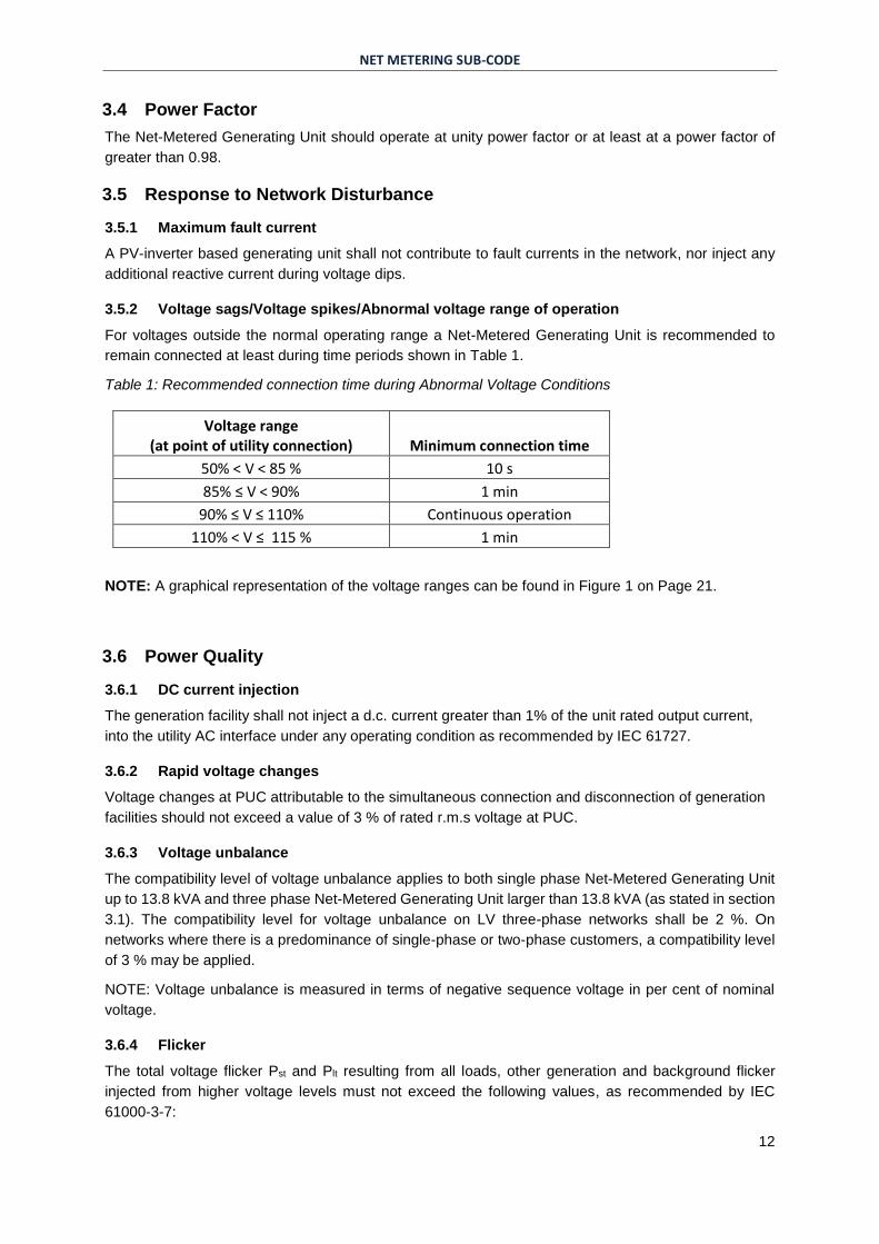
For voltages outside the normal operating range a Net-Metered Generating Unit is recommended to
remain connected at least during time periods shown in Table 1.
Table 1: Recommended connection time during Abnormal Voltage Conditions
Voltage range (at point of utility connection) Minimum connection time
50% < V < 85 % 10 s
85% ≤ V < 90% 1 min
90% ≤ V ≤ 110% Continuous operation
110% < V ≤ 115 % 1 min
NOTE: A graphical representation of the voltage ranges can be found in Figure 1 on Page 21.
3.6 Power Quality
3.6.1 DC current injection
The generation facility shall not inject a d.c. current greater than 1% of the unit rated output current,
into the utility AC interface under any operating condition as recommended by IEC 61727.
3.6.2 Rapid voltage changes
Voltage changes at PUC attributable to the simultaneous connection and disconnection of generation
facilities should not exceed a value of 3 % of rated r.m.s voltage at PUC.
3.6.3 Voltage unbalance
The compatibility level of voltage unbalance applies to both single phase Net-Metered Generating Unit
up to 13.8 kVA and three phase Net-Metered Generating Unit larger than 13.8 kVA (as stated in section
3.1). The compatibility level for voltage unbalance on LV three-phase networks shall be 2 %. On
networks where there is a predominance of single-phase or two-phase customers, a compatibility level
of 3 % may be applied.
NOTE: Voltage unbalance is measured in terms of negative sequence voltage in per cent of nominal
voltage.
3.6.4 Flicker
The total voltage flicker Pst and Plt resulting from all loads, other generation and background flicker
injected from higher voltage levels must not exceed the following values, as recommended by IEC
61000-3-7:
NET METERING SUB-CODE
13
Pst = 1.0
Plt = 0.8
For each VRPP, ETU shall apportion flicker emission limits based on flicker planning levels according
to IEC61000-3-7, existing background flicker levels, possible future installations and the total size of
VRPP to be connected. The methodology for apportioning VRPP-specific flicker limits shall be in-line
with IEC61000-3-7.
In the absence of any flicker limits provided by the Distribution Utility, the following limits to the
contribution of individual Net-Metered Generating Unit to voltage flicker shall apply:
Pst = 0.35
Plt = 0.3
Short term flicker (Pst) and long term flicker (Plt) emissions as measured at the PUC and the limits are
based on 95% probability levels.
3.6.5 Harmonics
For each VRPP, DU shall apportion individual harmonic voltage distortion limits based on planning level
for individual harmonic distortions (HD) and total harmonic distortion (THD) according to Article 19.70
of the National Electricity Distribution Code, existing background harmonics, possible future installations
and the total size of VRPPs to be connected, according to methodology described in IEEE std 519-
1992.
In the absence of any apportioned limits, individual harmonic voltage distortion limits for odd harmonics
shall not exceed 2% and in the case of even harmonics shall not exceed 1%; Total Harmonic Voltage
Distortion shall not exceed 3% at the POC.
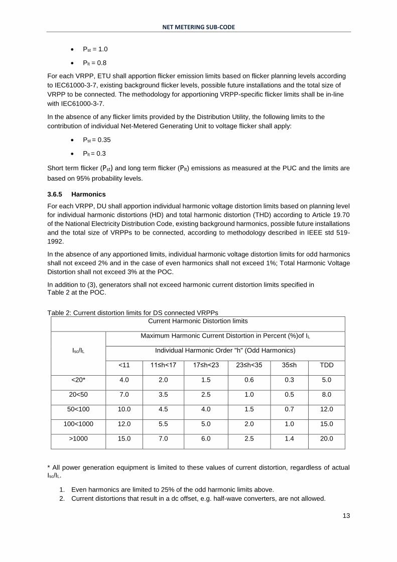
In addition to (3), generators shall not exceed harmonic current distortion limits specified in Table 2 at the POC.
Table 2: Current distortion limits for DS connected VRPPs
Current Harmonic Distortion limits
Isc/IL
Maximum Harmonic Current Distortion in Percent (%)of IL
Individual Harmonic Order "h" (Odd Harmonics)
<11 11≤h<17 17≤h<23 23≤h<35 35≤h TDD
<20* 4.0 2.0 1.5 0.6 0.3 5.0
20<50 7.0 3.5 2.5 1.0 0.5 8.0
50<100 10.0 4.5 4.0 1.5 0.7 12.0
100<1000 12.0 5.5 5.0 2.0 1.0 15.0
>1000 15.0 7.0 6.0 2.5 1.4 20.0
* All power generation equipment is limited to these values of current distortion, regardless of actual Isc/IL.
1. Even harmonics are limited to 25% of the odd harmonic limits above.
2. Current distortions that result in a dc offset, e.g. half-wave converters, are not allowed.
NET METERING SUB-CODE
14
3. Isc = maximum short-circuit current at POC.
4. IL = maximum demand load current (fundamental frequency component of generation current)
at POC.
5. TDD (Total Demand Distortion) = harmonic current distortion in % of maximum demand load (or
generation) current (15 or 30 min demand).
NET METERING SUB-CODE
15
4 Safety and Protection
4.1 System Safety and Protection
4.1.1 General
The Customer-generator shall be responsible for providing adequate protection for its facility under all
operating conditions regardless of whether or not the generation facility is in operation. Conditions
include but are not limited to single phasing of supply, system faults, equipment failures, abnormal
voltage or frequency, lightning and switching surges, excessive harmonic voltages, excessive negative
sequence voltages and islanding.
4.1.2 Synchronization
The utility voltage and frequency shall be within the steady state range for at least 5 minutes before
synchronizing the generation facility to the distribution network, i.e., voltage between 90% and 110% of
rated voltage and frequency between 49.8 Hz and 50.2 Hz.
During synchronisation the controller of the PV inverter must ensure that no transient currents or
voltages occur that would adversely impact the distribution network.
4.1.3 Protection and control devices
The Customer-generator’s protection system shall co-ordinate with the Supplier’s protection system.
Section 7 Annexes shows a single line diagram of an example connection.
4.1.3.1 Disconnect Device
The disconnect device should be located at the PGC, where the PV system and the buildings
electrical system interconnects, or at the distribution board. The disconnection device also
referred to as main switch, inverter supply shall be visible, easily accessible to service personnel
and should allow manual operation. See section 7.2 Annex B for more details.
4.1.3.2 Protective Relays
Protective relays shall be installed to trip the corresponding circuit breaker, or relays internal to
the inverter shall trip the inverter, during inadmissible network conditions.
Refer sections 4.1.7 and 4.1.8 for relay response times.
The admissible tolerance value between setting value and trip value of the voltage shall be
maximum ± 1% and the admissible tolerance for the frequency at the maximum ± 0.1%.
4.1.4 Reclosing
For a distribution network with automatic reclosing, the Net-Metered Generating Unit shall wait for at
least 5 minutes until the re-closer has normalized the portion of the system to which the facility is
connected before synchronizing back to the system according to section 4.1.2.
4.1.5 Loss of utility voltage (Islanding)
To prevent islanding, a Net-Metered Generating Unit shall cease to energize or otherwise de-energized
utility system, irrespective of connected loads or other generators within two seconds according to IEC
61727.
4.1.6 Earthing
Generation facilities and the associated interconnection systems must be grounded as per
recommendations according to the National Electricity Distribution Code.
NET METERING SUB-CODE
16
The grounding scheme of the generation facility shall not cause voltage disturbances or disrupt the
coordination of the ground fault protection on the local distribution network.
4.1.7 Over/under voltage
The Customer-generator must provide an automatic method of disconnecting its facility from the
Supplier’s distribution network if utility voltage excursions are beyond the limits stated in
Table 3. The limits according to
Table 3 apply to the lowest phase voltage in case of voltage dips and to the highest of the three phase
voltages in the case of voltage spikes.
Voltage protection device shall use the half wave r.m.s value from the 50 Hz fundamental voltage
component.
Table 3: Over/under voltage protection relay response time
Voltage Range (at Point of utility connection)
Maximum clearing time (s)
V < 50 % 0.16
50% <=V < 85 % 11
85% < V < 90% 61
110 % < V < 115% 61
115 % < V 0.16
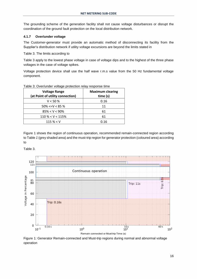
Figure 1 shows the region of continuous operation, recommended remain-connected region according
to Table 1 (grey shaded area) and the must-trip region for generator protection (coloured area) according
to
Table 3.
Figure 1: Generator Remain-connected and Must-trip regions during normal and abnormal voltage
operation
NET METERING SUB-CODE
17
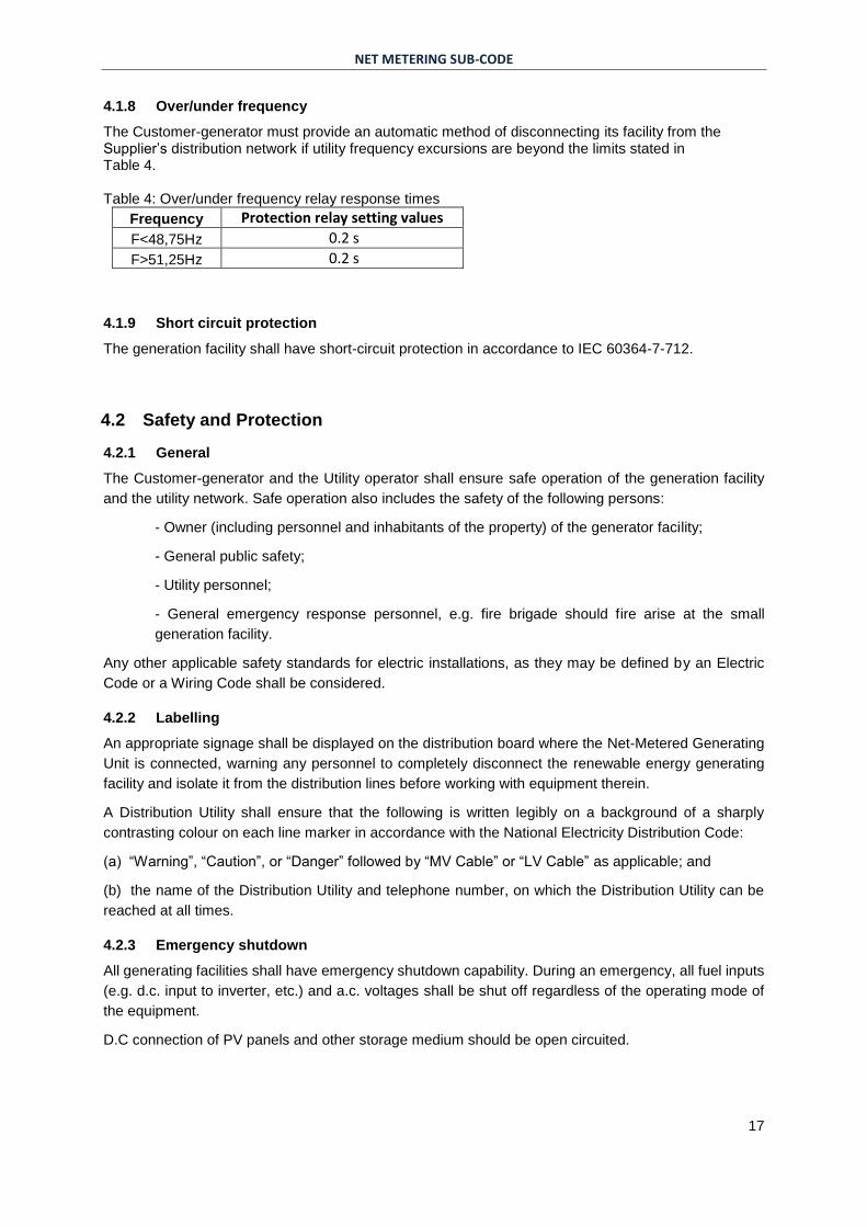
4.1.8 Over/under frequency
The Customer-generator must provide an automatic method of disconnecting its facility from the Supplier’s distribution network if utility frequency excursions are beyond the limits stated in Table 4. Table 4: Over/under frequency relay response times
Frequency Protection relay setting values
F<48,75Hz 0.2 s
F>51,25Hz 0.2 s
4.1.9 Short circuit protection
The generation facility shall have short-circuit protection in accordance to IEC 60364-7-712.
4.2 Safety and Protection
4.2.1 General
The Customer-generator and the Utility operator shall ensure safe operation of the generation facility
and the utility network. Safe operation also includes the safety of the following persons:
- Owner (including personnel and inhabitants of the property) of the generator facility;
- General public safety;
- Utility personnel;
- General emergency response personnel, e.g. fire brigade should fire arise at the small
generation facility.
Any other applicable safety standards for electric installations, as they may be defined by an Electric
Code or a Wiring Code shall be considered.
4.2.2 Labelling
An appropriate signage shall be displayed on the distribution board where the Net-Metered Generating
Unit is connected, warning any personnel to completely disconnect the renewable energy generating
facility and isolate it from the distribution lines before working with equipment therein.
A Distribution Utility shall ensure that the following is written legibly on a background of a sharply
contrasting colour on each line marker in accordance with the National Electricity Distribution Code:
(a) “Warning”, “Caution”, or “Danger” followed by “MV Cable” or “LV Cable” as applicable; and
(b) the name of the Distribution Utility and telephone number, on which the Distribution Utility can be
reached at all times.
4.2.3 Emergency shutdown
All generating facilities shall have emergency shutdown capability. During an emergency, all fuel inputs
(e.g. d.c. input to inverter, etc.) and a.c. voltages shall be shut off regardless of the operating mode of
the equipment.
D.C connection of PV panels and other storage medium should be open circuited.
NET METERING SUB-CODE
18
5 Metering
5.1 Net Metering
All meters utilized in the local distribution network shall be the property of the Supplier even when the
meters are located on the premises of the Customer-generator.
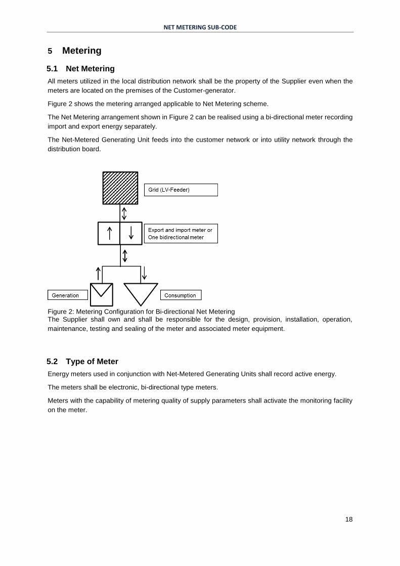
Figure 2 shows the metering arranged applicable to Net Metering scheme.
The Net Metering arrangement shown in Figure 2 can be realised using a bi-directional meter recording
import and export energy separately.
The Net-Metered Generating Unit feeds into the customer network or into utility network through the
distribution board.
Figure 2: Metering Configuration for Bi-directional Net Metering The Supplier shall own and shall be responsible for the design, provision, installation, operation,
maintenance, testing and sealing of the meter and associated meter equipment.
5.2 Type of Meter
Energy meters used in conjunction with Net-Metered Generating Units shall record active energy.
The meters shall be electronic, bi-directional type meters.
Meters with the capability of metering quality of supply parameters shall activate the monitoring facility
on the meter.
NET METERING SUB-CODE
19
6 Testing and Commissioning
6.1 General
The Distribution Utility shall have the right to witness testing and commissioning of Net-Metered
Generating Units upon completion of construction and shall have a copy of the test data.
The commissioning test shall be conducted after the interconnection system is installed and is ready for
operation.
Commissioning test shall include the following:
Verification and inspections
Production test
- Response to abnormal voltage
- Response to abnormal frequency
- Synchronization
Unintentional islanding functionality test
Cease-to-energize functionality test
The Distribution Utility shall not be responsible for verifying any control or signal wiring not directly
related to the interconnection protection.
Prior to final approval by the Distribution Utility or anytime thereafter, the Distribution Utility reserves the
right to test the relaying and control related to the protection of the distribution network.
If the Distribution Utility personnel is not present to witness the commissioning tests, the Distribution
Utility shall still consider approving the commissioning of the generation facility if the inverter of the
generation facility is certified according to section 0 and upon receiving a copy of the test data.
6.2 Inverter certification
The inverter of the Net-Metered-Generating Unit shall be product certified to comply with relevant IEEE
and IEC standards, as referred to by these interconnection rules.
IEEE standard certification must certify inverter harmonic emission levels according to IEEE 519:1992
or an updated version of a similar standard with limits as shown in section 3.6.5.
IEC standard certification must certify inverter’s performance according to IEC 61727, in relevance to
disconnection during loss of grid (4.1.5), islanding (Error! Reference source not found.) and excessive
.c current injection (3.6.1). The inverter’s islanding prevention measures must be tested and certified
according to IEC 62116 standard.
The person responsible for the installation of a Net-Metered Generating Unit must declare that the
installation of the system complies with all requirements according to IEC 60364-7-712 and this
document.
NET METERING SUB-CODE
20
7 Annexes
7.1 Annex A - Connection Example
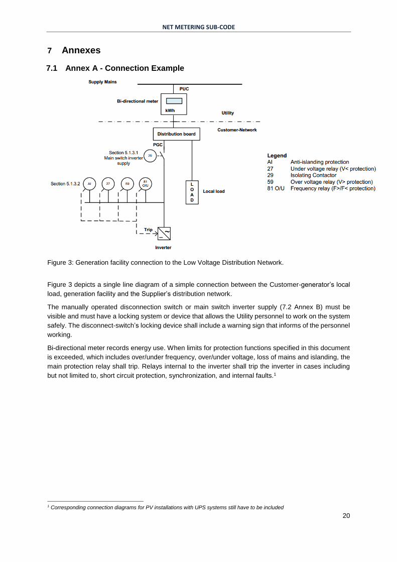
Figure 3: Generation facility connection to the Low Voltage Distribution Network.
Figure 3 depicts a single line diagram of a simple connection between the Customer-generator’s local
load, generation facility and the Supplier’s distribution network.
The manually operated disconnection switch or main switch inverter supply (7.2 Annex B) must be
visible and must have a locking system or device that allows the Utility personnel to work on the system
safely. The disconnect-switch’s locking device shall include a warning sign that informs of the personnel
working.
Bi-directional meter records energy use. When limits for protection functions specified in this document
is exceeded, which includes over/under frequency, over/under voltage, loss of mains and islanding, the
main protection relay shall trip. Relays internal to the inverter shall trip the inverter in cases including
but not limited to, short circuit protection, synchronization, and internal faults.1
1 Corresponding connection diagrams for PV installations with UPS systems still have to be included
NET METERING SUB-CODE
21
7.2 Annex B – Solar Supply Isolator in Switchboard
It is recommended that the interconnection of the grid connected PV system and the buildings electrical
system is undertaken at a switchboard or distribution board. This connection shall be at an a.c. solar
supply isolator located on the switchboard (or distribution board) where the PV system is connected.
This switch is referred to as main switch inverter supply. This isolator shall be lockable.
A switch or isolator being lockable means it needs a padlock or a similar device to lock it. In addition, a
switch or isolator shall have a tag or small plastic with inscription “DO NOT SWITCH ON-PERSON
WORKING ON SYSTEM” or similar.
The cable between the switchboard and inverter requires protection. Thus, a suitable rated circuit
breaker shall be used as the isolator. For example, a low voltage air circuit breaker can be used as an
isolator switch that can be used to connect or disconnect the circuit by manually moving an operating
handle to the ON or OFF position. Such a circuit breaker is also reset manually and can trip automatically
when the current in the circuit exceeds a predetermined value (in case of short circuit or over load
condition).