METERING CODE FOR RAJASTHAN GRID
25
METERING CODE FOR RAJASTHAN GRID PART-III of Grid Code (Finalised as per RERC order dated 28.10.2002) December 2002 Issued by : RAJASTHAN RAJYA VIDYUT PRASARAN NIGAM Ltd. Registered Office: Vidyut Bhawan, Janpath, Jyoti Nagar, Jaipur (India)
Transcript of METERING CODE FOR RAJASTHAN GRID

METERING CODE
FOR
RAJASTHAN GRID
PART-III of Grid Code
(Finalised as per RERC order dated 28.10.2002)
December 2002
Issued by :
RAJASTHAN RAJYA VIDYUT PRASARAN NIGAM Ltd. Registered Office: Vidyut Bhawan, Janpath, Jyoti Nagar, Jaipur (India)

Cost : Rs. 100.00
METERING CODE FOR RAJASTHAN GRID
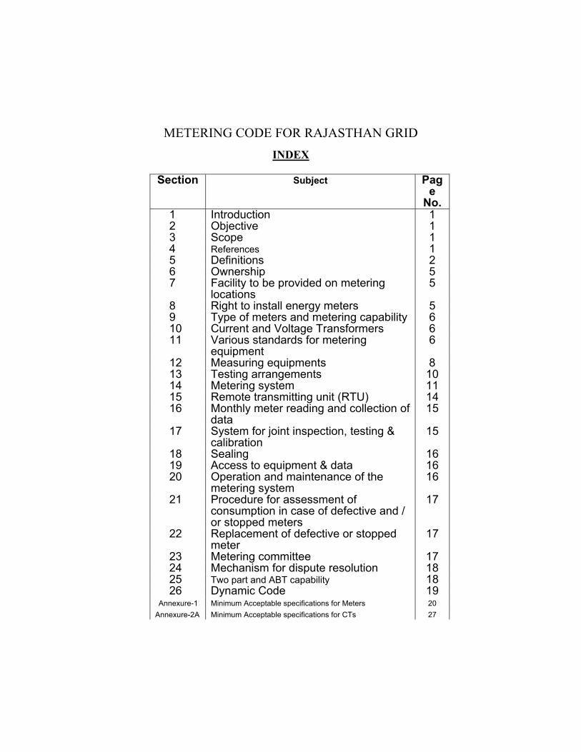
INDEX
Section Subject Page
No. 1 Introduction 1 2 Objective 1 3 Scope 1 4 References 1 5 Definitions 2 6 Ownership 5 7 Facility to be provided on metering
locations 5
8 Right to install energy meters 5 9 Type of meters and metering capability 6 10 Current and Voltage Transformers 6 11 Various standards for metering
equipment 6
12 Measuring equipments 8 13 Testing arrangements 10 14 Metering system 11 15 Remote transmitting unit (RTU) 14 16 Monthly meter reading and collection of
data 15
17 System for joint inspection, testing & calibration
15
18 Sealing 16 19 Access to equipment & data 16 20 Operation and maintenance of the
metering system 16
21 Procedure for assessment of consumption in case of defective and / or stopped meters
17
22 Replacement of defective or stopped meter
17
23 Metering committee 17 24 Mechanism for dispute resolution 18 25 Two part and ABT capability 18 26 Dynamic Code 19
Annexure-1 Minimum Acceptable specifications for Meters 20 Annexure-2A Minimum Acceptable specifications for CTs 27

Annexure-2B Minimum Acceptable specifications for CVTs 28 Annexure-2C Minimum Acceptable specifications for single phase PTs 29 Annexure-2D Minimum Acceptable specifications for 33 kV CT- PT set 30

METERING CODE FOR RAJASTHAN GRID
“In pursuance of the directions given by RERC in tariff order dated 24.03.2001 and on the basis of approval accorded by Rajasthan Electricity Regulatory Commission, Rajasthan Rajya Vidyut Prasaran Nigam Limited hereby prescribes the “Metering Code for Rajasthan Grid”.
1 Introduction The code prescribes a uniform policy in respect of electricity
metering in the different parts of power system of Rajasthan amongst the utilities i.e. RVUN, RVPN and the Distribution Companies in the state and shall form a part of Rajasthan Grid Code.
2 Objective The objective of the code is to define minimum acceptable
metering standards which will effect proper metering of the system parameters for the purpose of accountability, billing of electrical energy and will also provide information which will enable to operate the system in economic manner consistent with license conditions by licensee & RVPN to effect management of generation and transmission in a safe and economical manner.
3 Scope 3.1 The scope of the code covers the practices that
shall be employed and the facilities that shall be provided for the measurement and recording of various parameters like active/reactive/apparent power/energy, power factor, voltage, frequency etc.
3.2 The code also specifies the requirement of calibration, testing and commissioning for metering equipments. The code broadly indicates the technical features of various elements of the metering, data-communication and testing system, the procedure for assessment of consumption in case of defective and stopped meters and also lays down guidelines for resolution of disputes between different agencies.
3.3 The date of commencement of this code shall be 1.1.2003 and accordingly the concerned utilities shall commence its implementation.
4 References
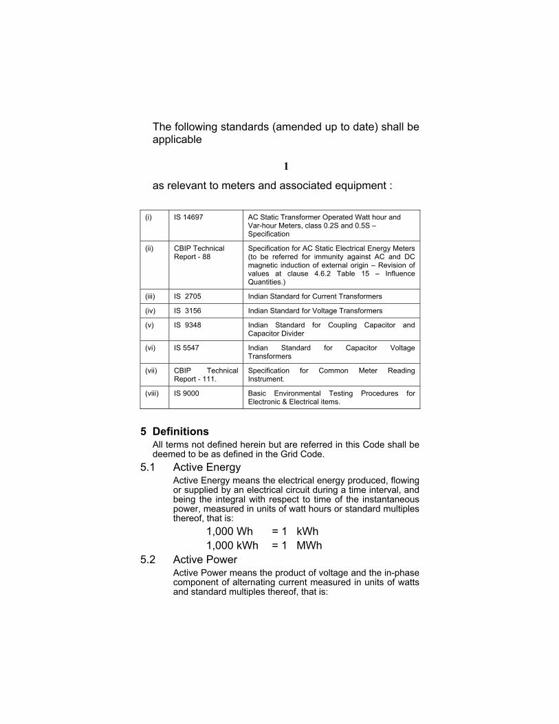
The following standards (amended up to date) shall be applicable
1
as relevant to meters and
(i) IS 14697 AC StaticVar-hour Specifica
(ii) CBIP Technical Report - 88
Specifica(to be remagneticvalues aQuantitie
(iii) IS 2705 Indian Sta
(iv) IS 3156 Indian Sta
(v) IS 9348 Indian SCapacitor
(vi) IS 5547 Indian Transform
(vii) CBIP Technical Report - 111.
SpecificaInstrumen
(viii) IS 9000 Basic EElectronic
5 Definitions
All terms not defined herein budeemed to be as defined in the
5.1 Active Energy Active Energy means the
or supplied by an electricabeing the integral with repower, measured in units thereof, that is:
1,000 Wh = 1,000 kWh =5.2 Active Power Active Power means the p
component of alternating and standard multiples the
associated equipment :
Transformer Operated Watt hour and Meters, class 0.2S and 0.5S – tion
tion for AC Static Electrical Energy Meters ferred for immunity against AC and DC induction of external origin – Revision of t clause 4.6.2 Table 15 – Influence s.)
ndard for Current Transformers
ndard for Voltage Transformers
tandard for Coupling Capacitor and Divider
Standard for Capacitor Voltage ers
tion for Common Meter Reading t.
nvironmental Testing Procedures for & Electrical items.
t are referred in this Code shall be Grid Code.
electrical energy produced, flowing l circuit during a time interval, and
spect to time of the instantaneous of watt hours or standard multiples
1 kWh 1 MWh
roduct of voltage and the in-phase current measured in units of watts reof, that is:

1,000 Watts = 1 kW 1,000 kW = 1 MW 5.3 Actual Metering poin Actual metering point me
and voltage sensing dewhich electricity is meter
5.4 Apparent Energy Apparent Energy means
the Apparent Power. 5.5 Apparent Power Apparent Power means
measured in units of vothereof, that is:
1,000 VA 1,000 kVA 5.6 Base Computer Syst
BCS means Based Cothe data down loadedalso process data into d
5.7 Central Data CollectioCentral Data Collectisystem located at a cenwhich is regularly Instations to which ilinks.
5.8 Common Meter Reading CMRI also known as an
reading instrument (Mcapable of interrogatingcurrent (ac) static electrithe corresponding metereading instrument progr
The CMRI can extract isurvey data, meter statumemory of the meter aretrieval at later stage.
5.9 Data Concentrator
2
t ans the physical location of currentvices i.e. CTs, VTs and meters at ed.
the integral with respect to time of
the product of voltage and current lt amperes and standard multiples
= 1 kVA = 1 MVA em (BCS) mputer System meant to handle from meter through CMRI and esired output forms.
n System (CDCS) on System means the computer tral point containing a data base updated from the Settlement t has dedicated communication
Instruments (CMRI or MRI) Interrogation Unit means a meter RI) with necessary accessories with various makes of alternating cal energy meters when loaded with r specific soft-ware(s) called meter am(s). nformation about energy data, load s and meter anomaly data from the s stored in preset cyclic order for

A centre to club the processed data received from various connected stations for onward transmission through dedicated communication channels to CDCS.
5.10 Demand Period Demand period means the period over which
Active Energy, Re ctive Energy or Apparent Energy are integr ted to produce average Demand Values. Fo settlement purpose, unless the context requirePeriod shall be of which shall finish arequirement.
5.11 Demand Values (a) Demand valu
energy, reactidrawn duringwhich shall co
(b) Demand valupower, expremeans four timor MVAh reperiod. The hour demandthe time of thOne of which
5.12 Meter Meter means a device
(import/export), reactive active power, reactive voltage, power factor and
5.13 Metering Equipment Metering Equipment
transformers (CTs & VTincluding alarms, circucollection outstations ameasuring equipment at
CT means current trancover either PT or CVT.
5.14 MMI (Man Machine I
aar3
s otherwise, each Demand 15 minutes duration, one of t 24:00 hours as per ABT
e energy :- Means active ve energy or apparent energy one demand period. One of mmence from 00.00 hours. e power :- Demand values ssed in MW, MVAr or MVA,
es the value of MWh, MVArh corded during any demand demand values are quarter s and these are identified by e end of the Demand Period. shall finish at 24:00 hours.
for measurement of Active energy energy (lag/lead), apparent energy, power, apparent power, current, frequency.
means meters, measurement s), metering protection equipment itry and their associated data
nd wiring which are part of the or relating to a site. sformers and term VT is used to
nterface)

Devices / softwares used by operating personnel to interact with computerized system / instrumentation etc.
5.15 Outstation Outstation means on-site equipment which receives and
stores data from a meter(s), and may perform some processing of the data before transmitting the metering data to the Settlement Instation on request. These functions may be facilitated in one or more separate units or be integral with the meter.
5.16 Outstation System Outstation System [Receoutstations linked to a sin
5.17 Reactive Power Reactive Power means
and the sine of the phasunits of volt amperesthereof, that is:
1,000 VAr 1,000 kVAr 5.18 Reactive Energy Reactive Energy means
the Reactive Power. 5.19 Remote Transmitting RTU means a unit for
sequential mode i.e. to signals from transducersit and to transmit receive
5.20 Transducer It is a device to c
(MW, MVA, Amp, Vfor transmission.
5.21 Settlement Instation Settlement Instation
system which colleroutine basis from sewhich is linked to CD
6 Ownership The ownership of the meterin
in whose premises the meterin
4
iving Station(s)] means one or more gle communication line.the product of voltage and current e angle between them measured in reactive and standard multiples
= 1 kVAr = 1 MVAr
the integral with respect to time of
Unit (RTU) data transmission in digital and transmit low level analogue / digital , switches, relays etc. connected to d signal to devices connected to it.
onvert high-level parameters olt etc.) into low-level signals
means a computer based cts or receives data on a lected out station system and CS.
g system shall belong to the agency g equipment is physically located.

7 Facility to be Provided on Metering Locations Each agency/constituent shall make available the
required space and the required outputs of the specified current and voltage transformers to facilitate installation of meters and RTUs in their premises and will also provide access to the agency/constituent for operation and maintenance of the equipment.
8 Right to Install Energy Meters Each constituent of the agency shall extend necessary
assistance to the other for installation of the meters and RTUs by providing required access to their premises and equipments. As and when required by the utility, the constituent/agencies shall enable the representatives of the utility with advance notice, to access, inspect, replace, test etc. any of the meters and RTUs for any utility installed in their premises.
5
9 Type of Meters and Metering Capability The meters & RTUs to be used shall be suitable for
measurement of bulk, interutility energy / power exchanges. The meters shall be all electronic (static) poly phase trivector type having facility to measure active, reactive and apparent energy/power in all four quadrants i.e. a true import export meter. All inter utility trade meters shall be bi-directional while capacitor bank meters and sub-station aux. meters shall be unidirectional if, bidirectional meters already exist, these will not be changed.
The frequency based energy meters suitable for Availability Based Tariff (ABT) shall also be provided.
10 Current and Voltage Transformers The meter shall be suitable for being connected
directly to the secondary of the voltage transformers (VTs ) and to the secondary of current transformers (1amp. or 5amp.).
11 Various Standards for Metering Equipment

For commercial transaction between the utilities, the metering shall be 3 phase 4 wire type having following various standards of metering equipment as given in Table–1, while detailed specifications of meters are indicated at Annexure-1.
Table-1 Sr. No.
Particulars Main Meter
Back up Meter
Capaci -tor Bank Meter
Sub-station Auxiliary Meter
Inter Discoms Meter
Second- ary Back up Meter
1 2 3 4 5 6 7 8
(1) Accuracy class
(a) Meter 0.2 S 0.5 S 0.5 S 1.0 0.5 S 0.5 S
(b) CTs 0.2 Existing 0.5 /1.0
Existing 0.5 /1.0
Existing 0.5 /1.0
Existing 0.5 /1.0
Existing 0.5 /1.0
(c) PTs / CVTs 0.2 Existing 0.5 /1.0
Existing 0.5 /1.0
Existing 0.5 /1.0
Existing 0.5 /1.0
Existing PTs 0.5 /1.0
(d) CT-PT sets for 33kV & 11kV feeders
0.2 Existing Existing Existing Existing Existing
1 2 3 4 5 6 7 8
(2) Salient aspect of meters
(a) Phase angle and ratio error compensat-ion of CTs & PTs
Not to be provid
ed
Not to be
provided
Not to be
provided
Not to be
provided
Not to be provided
Not to be provided
(b) Communic-ation port
(i) Communic-ation optical port
Yes Yes No No Yes Yes
(ii) Communic-ation port for remote reading
Yes Yes No No Yes Yes
(3) Whether an Import & Export both features are required
Yes Yes Yes No Yes Yes
(4) Meter memory for
Yes Yes No No Yes Yes
6

75 days
11.2.1 The test terminal blocks shall be provided on all
meters to facilitate testing of meters in situ. Main & back up meters of inter state / major generating stations shall be having the feature of draw out type modular units and shall have automatic CT short circuiting so that meter can be taken out for testing without shut down requirements.
11.2.2 Meters of inter state / major generating stations shall be capable of powered with 230 volt alternating current auxiliary supply and 110 volt or 220 volt DC supply of the substation so that metering core of PT/CVT is never loaded and in case of shut down on feeder/breaker, meter can be interrogated locally or remotely. It will normally be powered by AC auxiliary supply and will be switched over to DC supply only when AC auxiliary supply fails .
11.2.3 The meter shall have battery back-up (2 years), for its Real Time Clock (RTC).
11.2.4 The meters shall be equipped with necessary hardware/software to suit tariff requirements as may be called for from time to time.
11.2.5 Wherever feasible CTs of capacitor banks shall be either vectorially connected with main/backup meter using Interposing Current Transformers (ICTs). All new capacitor banks shall be procured with meter(s) having storage capacity of half hourly data in memory, reading by push button, MRI & RS-232 communication, separate registration of drawl/injection for above/preselected voltage ranges. Only one such meter may be provided for all capacitor banks of a substation on same bus and having CT with the same ratio or otherwise paralleled with ICTs.
7
11.2.6 Whenever check/back up meters for inter utility metering are proposed to be provided by a

discom, then its accuracy shall be same as that of main meter.
12 Measuring Equipments 12.1 Meters 12.1.1 The meter shall be 3 phase 4 wire type, capable to
record and display import and export kWh, kVArh, kVAh and maximum demand in kW and kVA for 3 phase 4 wire AC balanced/unbalanced load for a power factor having range of zero lagging to unity to zero leading in all 4 quadrants. In addition, meter shall also be capable of displaying, on demand, the present status of supply/load, missing potential, CT polarity, current unbalance, anomaly occurrence and logging of occurrences as well as load survey data etc. which shall be down loaded to a user friendly “Basic Computer Software” (BCS) through portable data collection devices or CMRI which shall be connected to optical communication port of the meter. Meter shall be equipped with self-diagnostic features also and be capable of recording average values based on their integration on time base for kWh, kVArh, kVAh for at least 75 days. Meter shall be capable of measuring fundamental as well as total energy including harmonics separately.
12.1.2 Energy measurement during demand period will be such that sampling in the meter is synchronized with the end of the time block otherwise energy measured in a demand period but not stored in that period shall be carried forward.
12.1.3 An LED glow or pulse output coincident with end of each demand period need be provided in the meter so as to ensure that demand integration coincided the preset time block.
8 12.1.4 Display

12.1.4.1 Present meter status, real time and date, cumulative energy registers, voltage, currents, power factor, present demand, frequency and meter serial number shall be available on demand through push button.
12.1.4.2 Any interrogation/read operation shall not delete or alter any stored meter data.
12.1.5 Memory (a) Numerical values of voltage/current, power factor and
cumulative energy registers as well as anomalies/tempered details alongwith date and time of logging of and restoration of anomalies (subject to the meter memory space) shall be logged in the meter memory and shall be available for retrieving with the help of the data collection devices (CMRI) through meter optical port and down loading to BCS.
(b) Memory in a static trivector meter shall not get ‘erased’ after reading or retrieving of data through MRI. Data shall be retained for a minimum of 75 days or shall not get erased from meter until replaced by fresh data. However, desired data can be erased from MRI, when memory of an MRI becomes full after downloading of readings of a number of meters, as there is fixed space made available in MRI for:
(i) Energy registers. (ii) Load survey data. (iii) Anomaly data etc.
When a fresh data is logged in the memory, the oldest data shall disappear automatically.
12.2 Current Transformers Three current transformers shall be used for 3
phase 4 wire measurement system. The secondary current rating of the CTs shall be 1 ampere particularly for 400kV and 220kV sub-stations but in other cases it may be 5 ampere. Either dedicated current transformers or dedicated core of current transformers shall be provided for metering and that wherever feasible, CTs (or their cores) feeding to main meters and backup/check meters will be separate. The errors of the current transformers shall be checked in the lab or at site. However if such facilities are not available, CT test
9
certificates issued by Govt. test house or Govt. recognized test agency shall be referred to.
The total burden connected to each current transformer shall not exceed the rated burden of CT.
12.3 Voltage transformers 12.3.1 Either electromagnetic voltage transformers (VT)
or capacitive voltage transformers (CVT) may be used for metering purpose. Hereinafter term VT is used to cover either PT or CVT. The secondary voltage per phase shall be 110/√3 volts per phase. Either dedicated voltage transformers or dedicated core of voltage transformers shall be provided for metering and that wherever feasible, VTs (or their cores) feeding to main meters and backup/check meters will be separate. VT fuses of proper rating shall be provided at appropriate locations in the circuit.
12.3.2 The errors of the VTs shall be checked in the lab or at site. However if such facilities are not available, VT test certificates issued by Govt. test house or Govt. recognized test agency shall be referred to.
The total burden connected to each VT shall not exceed the rated burden of VT.
12.4 The current transformers and voltage transformers shall meet the requirements as per the relevant standards. Where a combined CT/PT unit is provided, the accuracy shall be as specified under relevant IS. Minimum acceptable specification are enclosed at following Annexures :-
(i) Current Transformers - Annexure -2A (ii) CVTs - Annexure-2B (iii) Single phase PTs - Annexure-2C (iv) 33 kV CTPT Set - Annexure-2D
13 Testing Arrangements 13.1 Two types of test facilities shall be available: (a) Automatic meter test bench with high accuracy,
static source and 0.02S class electronic reference standard meter. One bench shall be located at
each Discom headquarters (i.e. at Jaipur, Ajmer and Jodhpur). These benches with 0.02 class reference standard shall also be used for checking and calibration of portable testing equipments.
(b) Portable test set with static source and electronic reference meter of 0.1 class shall be used for verification and joint testing of accuracy of static trivector meters at si on regular/routine basis.
13.2 Separate test termin blocks for testing of main and check meters shone meter is undecontinues to record period. Where onlyadditional meter shaenergy during the teso that while the maother meter can recometer under testing.
14 Metering System 14.1 The metering syste
check, backup and the event of main mbecoming defective billing shall be (a) msecondary backup.
14.2 Generating Stations Meters shall be installed
each auxiliary transfogenerating stations to wenergy delivered by the p
14.2.1 For measurement of enstations within the stateoutgoing feeder at the meter for billing purposethe other end of the secondary back-up meteauxiliary transformer shconsumption recorded bwith the consumption re
te al10
all be provided so that when r testing, the other meter actual energy during testingone/main meter exists, an ll be put in circuit to record
sting period of the main meter in meter is under testing, the rd energy during the period of
m shall comprise of main, secondary backup meters. In eter or more than one meter the order of precedence for ain (b) check (c) backup (d)
on each generator as well as on rmer and outgoing feeders at ork out energy generated and net ower station in the power system. ergy supplied by major generating , meters shall be provided on each power station designated as main . Meters shall also be provided on above EHV feeders to serve as r. Meters on each generator & each all work as backup meters. The y main meter shall be compared
corded by secondary backup meter

on EHV feeder to work out transmission losses as well as to monitor the correct functioning of both meters. In case of any defect or major deviations in the consumption recorded between both the meters of EHV feeder at a later stage of their installation, the average percentage difference of consumption between main meter and secondary backup meter based on last one year figures shall be added / subtracted or compensated in the consumption recorded by the secondary backup meter.
14.2.2 Mini Hydel Stations For the energy supplied by mini hydel stations to the RVPN or Discom as the case may be, CT/VT units of 11/33kV voltage rating having two identical metering cores with main and check meters shall b rovided at energy transfer points preferably at the generat station.
14.3 Metering for Transfer oflines connected to major
14.3.1 Metering equipment shainterstate EHV lines.
14.3.2 The above meters provilines connected to majorshall have following facili
(a) Metering equipinternal modemremote transmithe meter meinformation linkSwitched TelepLine Carrier CoSAT Network, telemetry like plow power radio
(b) The metering etype modular mautomatic CT sshall be projecspace and site
(c) The meters shawith 230V, AC 220V DC sup
e ping11
power through interstate lines and generation stations: ll be provided at receiving end ofded on interstate lines, and on the generating stations within the state ties: ment shall have external / so as to be capable of
ssion of all data available in mory through any of the viz. radio frequency, Public hone Network (PSTN), Power mmunication (PLCC) lines, V-Mobile and other means of rivate network of transco or . quipment shall be of draw out
etering units with facility of hort circuiting. Meter mounting tion type or rack type as per requirement. ll be capable of powered up auxiliary supply and 110V or ply of sub-station so that

metering cores VT is never loaded. The meter will normally be powered up by AC auxiliary supply and will be switched over to DC supply only when AC auxiliary supply fails.
(d) The meter shall be capable of data transmission to RTU’s as well Intelligent Electronic Device (IED). The format / protocol of communication for data retrieval and data telex should be made known to owner of meter by meter supplier.
14.4 Metering between Transco & Discoms 14.4.1 For measurement of power delivered by RVPN to Discoms,
following type of metering shall be provided on the LV side of EHV transformers (33kV or 11kV):
(a) Main Meters: The main meters shall be provided on LV secondary side of EHV transformers with dedicated CTs, VTs / CT-VT sets of 0.2 class accuracy.
(b) Back-up Meters: he back-up meters shall be provided on the e ting CT / VTs having 0.5 class accuracy of the 33
(c) Secondary backupshall be provided transformers on th
14.4.2 Whenever check / backare proposed to be paccuracy shall be same a
14.4.3 The meters to be provide
(a) Metering equipinternal modemremote transmithe meter meminformation linkSwitched TelePower Line Calines, V-SAT means of telemtransco or low p
Txis12
/11 kV outgoing feeders. meters: Secondary backup meters at a later stage on EHV side of the e existing CTs and VTs. up meters for inter utility metering rovided by a Discom(s), then its s that of main meter. d shall have the following facilities:ment shall have external / so as to be capable of
ssion of all data available in ory through any one of the viz. radio frequency, Public phone Network (PSTN) , rrier Communication (PLCC) Network, Mobile and other etry like private network of
ower radio.

(b) The meter mounting shall be projection type or rack type as per space and site requirement.
(c) The meters shall be capable of data transmission to RTUs as well as IED. Format/protocol of data retrieval & data telex should be made known to owner of meter by meter supplier.
14.5 Inter Discom Metering
The energy meters shall be provided at such points of the power lines connecting two Discoms so that the line in between is not tapped by the either Discoms.
14.6 Sub-station Auxiliary Consumption Metering The RVPN’s sub-stations auxiliary consumption shall be
recorded on HV/LV side of station auxiliary transformers as mutually agreed through class 1.0 static kWh meters.
14.7 Time Synchronization The time synchronization in all the meters under clause 14.0 should be from base computer through communication system and modem. The base computer shall be equipped with GPS signal receiver for time synchronization of the meters connected through relevant communication system and modem. As a standby measure, the CMRI will be used for time synchronization of the individual meter. There should also be provision in the base computer to synchronize time at preset time daily with respect to GPS clock of SLDC or central billing station.
13
15 Remote Transmitting Unit (RTU) 15.1 Following data (instantaneous system parameters) shall be
made available through transducers and RTUs from selected individual stations to sub-load despatch centre and load despatch centre continuously. (a) MW (Import/export). (b) MVAr (Lag plus lead). (c) Voltage. (d) Current.
(e) Frequency.

(f). The status of various isolators, circuit breakers and transformer tap positions.
RTUs & Transducers requirement shall not be considered
wherever meters have the capability of transmitting various parameters to SLDC / sub LDC exists.
15.2 The accuracy of the transducers shall be 0.2% of span. 15.3 The transducers and RTU’s shall conform to relevant
international / national standards. 15.4 The transducers shall be 3 phase 4 wire type for MW and
MVAr measurement purposes. 15.5 Single transducer giving output of MW, MVAr, voltage,
frequency and ampere shall be preferred in place of individual transducers for each metering point. The transducers shall be connected to 0.2 class CTs and VTs and housed inside the meter box of the check meter meant for metering purpose.
15.6 Since the above metering scheme is for commercial metering purpose therefore the complete CT wiring including energy meter, meter test terminal block and transducers shall be housed in the metering cubicle which shall be kept sealed. The output of the transducers shall be connected to RTU through screened signal cable. The RTUs shall be located in the PLCC room. The size of the CT & VT cable to the transducer shall be same as that provided in the metering circuit.
15.7 The various data collected by transducers and fed to RTU shall be processed in the RTU and output will be provided in digital telegraphic form. Transmission of these data to the load despatch centre can be through any of the information link like Radio frequency, PLCC (Power Line Carrier Communication), PSTN (Public Switched Telephone Network), VSAT, Mobile and other means of Telemetering like private network of Transco or low power radio.The data shall be again processed at load despatch end in Data Concentrator Unit and converted to analog data and displayed on the monitor screen. The RTU shall be utilized for monitoring and also for remote control of feeders / breakers located at remote sub-stations.
14
15.8 Format/protocol of data retrieval & data telex should be made known to owner by the supplier.
16 Monthly Meter Reading and Collection of Data The RVPN and concerned Vitran Nigams/Utpadan Nigam shall
jointly read the meters through their authorized representatives on 1st of every month at 12.00 Hrs. and shall retrieve meter

reading data. A copy of meter reading sheet duly signed will be supplied by RVPN to Vitran Nigam or RVUN as the case may be and one copy shall be kept sealed for future reference. Wherever meters are in position or in operation the tele-metered data shall be retrieved from the optical communication port of the meter.
17 System for Joint Inspection, Testing & Calibration 17.1 The metering points between RVUN, RVPN and Discoms
shall be regularly inspected twice in a year or at an interval as mutually agreed jointly by both the agencies involved for despatch and receipt of energy. Since the static trivector meters are calibrated through softwares at the manufacturers works, therefore during joint inspection only accuracy of the meters and functioning shall be verified and certified jointly by both the agencies. In case of any doubt or defect, the meter shall be replaced then and there or calibrated. In later case, error correction as determined will be applied to the meter reading for the purpose of billing contingency referred at clause 21 & comparing their readings. To cover for loss of time, spare meters shall always be kept available with the agency to whom the meter/metering point belongs. After testing, the meter shall be sealed and a joint report shall be prepared giving details of testing work carried out, old seals removed, new seals affixed etc. The agency in whose premises the meter is located shall be responsible for proper security, protection of the metering equipment and sealing arrangement.
15
17.2 Joint inspection shall also be carried out as and when difference in meter readings (so corrected) exceeds the sum of maximum error as per accuracy class of main & back up meter. The meters provided at the sending end as well as at the receiving end shall be jointly tested/calibrated on all loads and power factors as per relevant standard through static phantom load .
18 Sealing 18.1 All tariff metering system shall be jointly sealed by the
representative of the concerned parties as per the procedure agreed upon.
18.2 No seal, applied pursuant to this metering code, shall be broken or removed except in the presence of or with the prior consent of the agency affixing the seal or on whose behalf the seal has been affixed unless it is necessary to do so in circumstances where (i) both main and check meters are malfunctioning or there occurs a fire or similar hazard

and such removal is essential and such consent can not be obtained (ii) such action is required for the purpose of attending to the meter failure. Where verbal consent is given it must be confirmed in writing forthwith.
18.3 Each party shall control the issue of its own seals and sealing pliers, and shall keep proper register/record of all such pliers and the authorized persons to whom these are issued.
19 Access to Equipment & Data Each constituent of the agency (Utility) on request with advance
notice, shall grant full right to metering equipment for other agency’s employees, agents/duly authorized representative for inspecting, testing, calibrating, sealing, replacing the damaged equipment, collecting the data, joint reading recording and other functions necessary and as mutually agreed.
20 Operation and Maintenance of the Metering System 20.1 The operation and maintenance of the metering system
includes proper installation, regular maintenance of the metering system, checking of errors of the CTs, VTs and meters, proper laying of cables and protection thereof, regular/daily reading meters and regular data retrieved through MRI & BCS, attending any breakdown/fault on the metering system etc.
16
20.2 The maintenance of the meters shall be the exclusive responsibility of the owner of the meters, the ownership of meters has been indicated at clause 6 above.
21 Procedure for Assessment of Consumption in case of Defective and/or Stopped Meters
Whenever a meter goes defective, the consumption recorded by the check meter / backup meter / secondary backup (i.e. receiving end meters) shall be referred. The details of the malfunctioning along with date and time and snaps shot parameters along with load survey shall be retrieved from the main meter. The exact nature of the mal-functioning shall be brought out after analysing the data so retrieved and the consumption / losses recorded by the main meter shall be assessed accordingly. If main as well as back up metering systems become defective, the assessment of energy consumption for the outage period shall be done from the backup meters by the concerned parties as mutually agreed or at the level of Metering Committee (vide clause 23).
22 Replacement of Defective or Stopped Meter

The owner of the meter shall maintain spare inventory of meters in sufficient quantity, so that down - time is minimized.
23 Metering Committee 23.1 RVPN shall be responsible for managing and serving the
Metering code among the constituents for discharging its obligation under the licence.
23.2 The Grid Code Review Panel shall establish a Metering Committee in accordance with Grid Code and such Committee shall consist of the following:
(a) A Chairman who is an officer designated by RVPN. (b) A Member (Secretary) who is also an officer from RVPN. (c) One representative from each of the RVUN, JVVN, AVVN &
JdVVN. (d) One member from Power Grid (NRLDC). (e) One Member from IPP’s (functioning) & major CPPs (with
installed capacity exceeding 50 MW) connected to the RVPN’s transmission system.
23.3 The rules to be followed by the Committee in conducting their business shall be formulated by the Committee themselves and shall be approved by Grid Code Review Panel. The Committee shall meet at least once in six months and conduct the following functions.
17
(a) To keep Metering Code and its working under scrutiny and review.
(b) To consider all requests for amendment to the Metering Code which any user makes.
(c) To publish recommendations for changes to the Metering Code together with the reason for the change and any objection, if applicable.
(d) To issue guidance on the interpretation and implementation of the Metering Code.
24 Mechanism for Dispute Resolution Any disputes relating to metering with RVUN / DISCOM / other
utilities shall be settled in accordance with procedures given under relevant PPAs or Bulk Supply Agreements as the case may be.
25 Two Part and ABT Capability 25.1 The ABT compliant meter will have provision to compute and
store average active and reactive energy and load data with respect to system frequency and the integration of the data

i.e. average Wh & Varh, and average frequency for 15 minutes block will be available in each meter. Minimum acceptable specification of these meters shall be as per column 1 and 2 of Annexure-1.
Meters shall also have reactive high and reactive low volt ampere hour registers for total drawl, high & low system voltage drawl. The Discom-wise summation of kWh, kW, PF, demand scheduled interchange/ unscheduled interchange will be done at the main computer station provided at central billing station or at Load Despatch Centre.
25.2 The metering arrangement between RVPN and Discom The metering arrangement between RVPN and Discom shall
comprise of static trivector meter on the LV side of EHV Transformer.
(a) Frequency based ABT compliant meters shall be provided on 220 kV / 132 kV lines feeding each Discom. The function of these meters will be as under:
(i) To measure Discom-wise schedule and unschedule interchange of energy.
18
(ii) To monitor and measure Discom-wise kW/kVAr, kVA demand, hourly power factor and MVAr flow including MVAr exchange above 103% and below 97% of rated system voltage.
For this purpose, the various parameters shall be integrated at one centrally located station preferably at load despatch centre at Jaipur through computer and suitable software.
(b) Static trivector meters to be provided on LV secondary side of all EHV transformers. The function/duty of this meter will be as under:
(i) Measurement of kWh energy supplied to Discoms for billing purpose.
(ii) KW/kVA demand and power factor, hourly as well monthly caused by Discom on each EHV transformer.
26 Dynamic Code To have a dynamic code is very valuable aspect because there
is continuous and very fast upgradation in the technology of metering and communication, therefore the Code may be reviewed periodically.
***********

19