NCSX Engineering Design Document Design Description Vacuum ...
39
NCSX Engineering Design Document Design Description Vacuum Vessel (WBS 12) and In-vessel Components NCSX Final Design Review May 19-20, 2004
Transcript of NCSX Engineering Design Document Design Description Vacuum ...

NCSX Engineering Design Document Design Description Vacuum Vessel (WBS 12) and In-vessel Components
NCSX Final Design Review
May 19-20, 2004
ii
Table of Contents
1 Design Overview ..................................................................................................................................................1
2 Design Requirements and Constraints...............................................................................................................3
3 Design Description and Performance.................................................................................................................5
3.1 Vacuum Vessel ..................................................................................................................................................5 3.2 In-Vessel Components.....................................................................................................................................16 4 Design Basis........................................................................................................................................................20
4.1 Geometry Optimization ...................................................................................................................................20 4.2 Design Criteria.................................................................................................................................................20 4.3 Vacuum Vessel Structural Analysis ................................................................................................................21 4.4 Vacuum Vessel Thermal Analysis...................................................................................................................21 4.5 Vessel Tracing Thermo-Hydraulic Analysis....................................................................................................25
4.5.1 Bakeout....................................................................................................................................................25 4.5.2 Cooldown between Pulses .......................................................................................................................26 4.5.3 Port Extension Resistance Heaters...........................................................................................................26
5 Design Implementation .....................................................................................................................................29
5.1 Manufacturing Studies and In-house R&D......................................................................................................29 5.2 Manufacturing Development and Prototype Fabrication.................................................................................29 5.3 Component Procurement and Fabrication .......................................................................................................30 5.4 Vacuum Vessel and Field Period Assembly ....................................................................................................30 6 Reliability, Maintainability, and Safety ...........................................................................................................31
7 Cost and Schedule..............................................................................................................................................32
8 Risk Management ..............................................................................................................................................33
8.1 PFCs ................................................................................................................................................................33 8.2 Vacuum vessel .................................................................................................................................................33

iii
List of Figures
Figure 1 Cut-Away View of the Stellarator Core Assembly ....................................................................................1 Figure 2 Space allocations between plasma and modular coils ...............................................................................2 Figure 3 Vacuum vessel geometry showing thermal insulation...............................................................................6 Figure 4 Vacuum Vessel dimensions..........................................................................................................................6 Figure 5 VV Port Arrangement..................................................................................................................................8 Figure 6 Vacuum vessel vertical and lateral supports..............................................................................................9 Figure 7 Typical Vacuum Vessel shell segmentation................................................................................................9 Figure 8 Vacuum Vessel port stub concept .............................................................................................................10 Figure 9 Vessel with cooling line tracing .................................................................................................................11 Figure 10 Vessel assembly joint spacer and weld prep concept.............................................................................12 Figure 11 Final assembly of three field periods ......................................................................................................13 Figure 12 Neutral Beam Injection into plasma .......................................................................................................14 Figure 13 Inboard RF Launcher Ports ....................................................................................................................15 Figure 14 Removable Port Cover for Personnel Access .........................................................................................16 Figure 15 Cross-Section of Limiter Concept at VV Field Joints ...........................................................................17 Figure 16 Internal Liner with Full Complement of Panels ....................................................................................18 Figure 17 Panel-to-Rib Attachment Concept ..........................................................................................................19 Figure 18 Vacuum vessel geometry optimization process ......................................................................................20 Figure 19 Thermal Ratcheting of VV Temperature ...............................................................................................23 Figure 20 Racheting Temperature Dependence on Clamp Spacing.....................................................................23 Figure 21Vacuum Vessel Heat Balance ...................................................................................................................24 Figure 22 Heat Distribution On 8 Inch Port With 65 Watt Heater.......................................................................27 Figure 23 Heat Distribution On 8 Inch Port With 54 Watt Heater.......................................................................28 Figure 24 Prototype Vacuum Vessel Segment (PVVS)...........................................................................................30

iv
List of Tables
Table 1 NCSX Parameters..........................................................................................................................................1 Table 2 Requirements for the Vacuum Vessel and In-Vessel Components............................................................3 Table 3 Vacuum Vessel Parameters...........................................................................................................................5 Table 4 Vacuum Vessel Port Dimensions ..................................................................................................................8 Table 5 Material Properties for the VV and PFCs .................................................................................................21 Table 6 VV and PFC Operational Parameters .......................................................................................................22 Table 7 Insulation thicknesses assumed in study ....................................................................................................24 Table 8 Thermal Loads. Rows correspond to insulation thicknesses listed in Table 9.......................................25

NCSX Engineering Design Description Vacuum Vessel and In-Vessel Components
1
1 DESIGN OVERVIEW
The stellarator core is an assembly of four magnet systems that surround a highly shaped plasma and vacuum chamber. The coils provide the magnetic field required for plasma shaping and position control, inductive current drive, and error field correction. The vacuum vessel and plasma facing components are designed to produce a high vacuum plasma environment with access for heating, pumping, diagnostics, and maintenance. All coils are cryo-resistive and operate at liquid nitrogen temperatures, so the entire system is surrounded by a cryostat. Figure 1 shows a cutaway view of the stellarator core assembly. This document describes the vacuum vessel and in-vessel components.
Figure 1 Cut-Away View of the Stellarator Core Assembly
The overall parameters of NCSX are listed in Table 1. The principal feature of NCSX is the set of modular coils that surround and shape the plasma. There are three field periods with 6 coils per period, for a total of 18 coils.
Table 1 NCSX Parameters
Parameter Value Major radius 1.4 m Minor radius .33 m Bmax 2 T Plasma current Up to 350 kA TF coil configuration +/- 0.5 T, 1/R (18 coils)
3 MW NBI 6 MW NBI (future upgrade)
Plasma heating methods
6 MW ICH (future upgrade)

NCSX Engineering Design Description Vacuum Vessel and In-Vessel Components
2
Nestled inside the coil set is a highly shaped, three-period vacuum vessel, which means the geometry repeats every 120º. Stellarator symmetry also causes the geometry to be mirrored every 60º so that the top and bottom sections of the first (0º to 60º) segment can be flipped over and serve as the corresponding sections of the adjacent (60º to 120º) segment. The vessel will be constructed in full field periods and joined together at welded joints. Numerous ports are provided for heating, diagnostics, and maintenance access. Several port sizes and shapes are used to best utilize the limited access between modular coils.
The plasma facing components (PFCs) inside the vessel will be introduced in stages after initial operation as the plasma heating systems are upgraded. The first complement of PFCs will likely feature a simple set of poloidal limiters at the three v=1/2 symmetry planes which correspond to the vessel field joints. Later upgrades will provide a contoured liner with a divertor. The liner will be constructed of molded carbon fiber composite (CFC) panels mounted on a frame of poloidal rings.
One of the challenges for the design is the allocation of space among the components. Specially developed computer codes have been used to optimize the winding path trajectory to satisfy stringent physics requirements while not violating engineering constraints on bending radii, coil-to-coil spacing, coil-to-plasma spacing, and access for neutral beam injection. The coil cross section is further limited by the space requirements for the PFCs, PFC supports, magnetic diagnostics, vacuum vessel, thermal insulation, and coil clamping features. The space allocations are shown in Figure 2.
Figure 2 Space allocations between plasma and modular coils

NCSX Engineering Design Description Vacuum Vessel and In-Vessel Components
3
2 DESIGN REQUIREMENTS AND CONSTRAINTS
The vacuum vessel and in-vessel components are required to provide ultra-high vacuum conditions and power handling capability for high performance plasma operation. The basic requirements are listed in Table 2. These requirements for the vacuum vessel are defined in the System Requirements Document for the Vacuum Vessel System (WBS 12)1. Upgrade requirements for the in-vessel components are defined in the General Requirements Document2.
Table 2 Requirements for the Vacuum Vessel and In-Vessel Components
Vacuum vessel requirements
General /geometry The vessel will fill as much of the coil-bore volume as possible consistent with assembly of the coils over the vessel and necessary insulation and cooling tube space.
The vacuum vessel interior and all in-vessel metallic components shall be electro-polished prior to installation when practicable, otherwise mechanically lapped to a 32-microinch finish.
Access ports shall be provided for diagnostics, heating, and maintenance / reconfiguration of in-vessel components.
Space shall be provided on the inboard side, at the v=1/2 symmetry plane, for the installation of ICRH launchers as a future upgrade.
Plasma facing components (PFCs) requirements
General PFCs are required (as future upgrades) to support power and particle-handling research, protect the vacuum vessel and in-vessel components from the plasma and from neutral beam shine-through., and limit sputtering of high Z impurities.
The design is able to accommodate the installation of a full liner.
Areas which are expected to come in contact with the plasma shall be armored with carbon-based, i.e. graphite or carbon fiber composite (CFC ) components, which shall be bakeable in situ to 350ºC
Upgrade configurations (to be implemented during operations)
Future upgrades shall be accommodated by designing a flexible system that can be implemented in stages. It shall provide the potential to implement a slot divertor with active pumping in a sealed plenum, up to 100% wall coverage, capability to electrically bias regions of the plasma boundary relative to each other and the vacuum vessel..
Power handling The upgrade configuration shall be capable of accommodating heat loads associated with up to 12MW of plasma heating power for 1.2s (including 6MW of neutral beam injection)
1 NCSX-BSPEC-12-00, System Requirements Document for the Vacuum Vessel Systems (WBS 12) 2 NCSX-GRD-00, NCSX General Requirements Document

NCSX Engineering Design Description Vacuum Vessel and In-Vessel Components
4
Vacuum Vessel and In-vessel Component Requirements
Disruption requirements The device shall be designed to withstand electromagnetic forces due to major disruptions characterized by the disappearance of the plasma at the maximum plasma current (350 kA).
Magnetic permeability The relative magnetic permeability of the vacuum vessel and in-vessel components shall be less than 1.02 unless approved by the project.
Electrical (eddy current) requirements
The vessel and in-vessel structures shall be designed with stellarator symmetry to minimize field errors from unsymmetrical eddy currents.
The time constant of the vacuum vessel and in-vessel structures must be less than 10 ms.
Life requirements All components must be designed for 130,000 full power shots.
Temperature requirements
Bakeout temperature The vacuum vessel shall be bakeable at 350ºC. (Initial bakeout temperatures will be 150ºC, limited by the VV Heating and Cooling system capability.)
Pre-shot operating temperature
The pre-shot operating temperature of the vacuum vessel shall be capable of being maintained in the range of 40ºC-100ºC without ratcheting.
The pre-shot operating temperature of the plasma facing components will be such that the peak temperature during a shot will not exceed 1200ºC to avoid carbon blooms.
NCSX Engineering Design Description Vacuum Vessel and In-Vessel Components
5
3 DESIGN DESCRIPTION AND PERFORMANCE
3.1 Vacuum Vessel
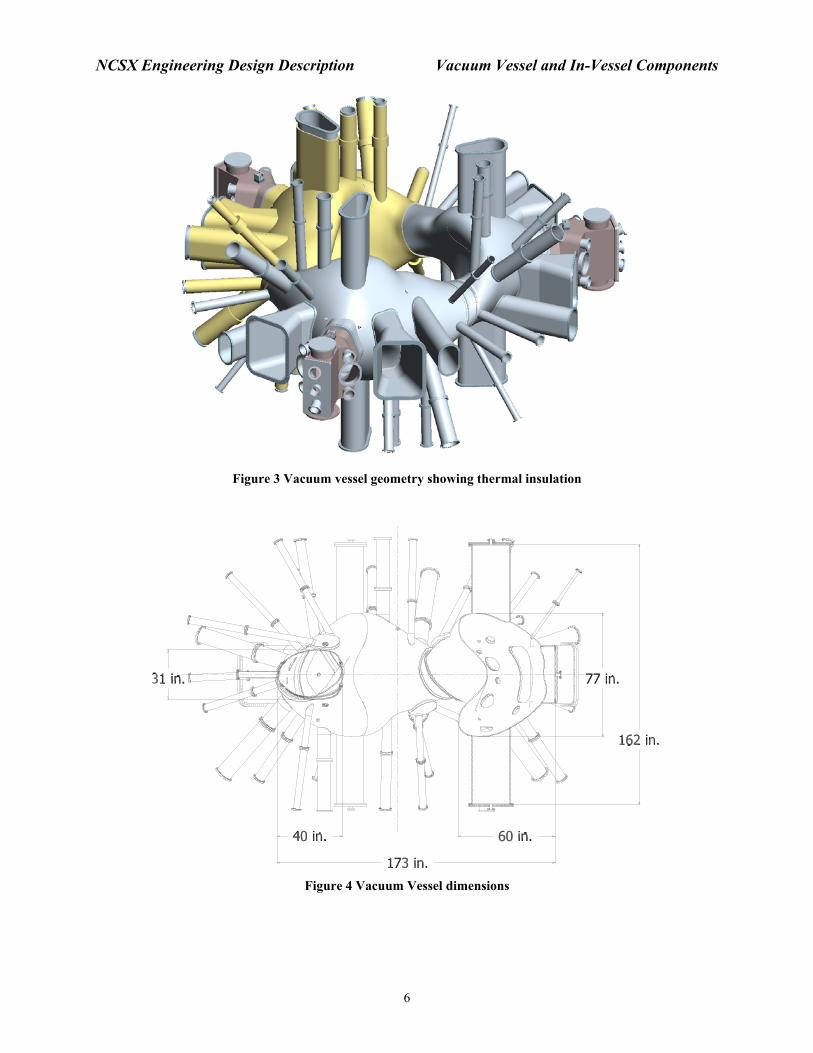
The vacuum vessel is a highly shaped, three-period structure, i.e. a geometry that repeats every 120º toroidally. The geometry also has stellarator symmetry, i.e. it is mirrored every 60º so that the top and bottom sections of the first (0º to 60º) segment can be flipped over and serve as the corresponding sections of the adjacent (60º to 120º) segment. Table 3 lists the main vacuum vessel parameters. Figure 3 and Figure 4 illustrate the basic vessel geometry.
The vessel will be baked to 350ºC and operate with a nominal operating temperature of 40-100ºC. The vessel is maintained at temperature by helium gas circulated through tracing lines attached to the vessel exterior. The vessel is insulated on its exterior surface to provide thermal isolation from the modular coils, which operate at cryogenic temperature (80K). Inconel 625 is the material chosen for the vessel shell. It was selected over stainless steel primarily because of its low permeability (both in the parent and weld material), high electrical resistivity, and high strength at elevated temperature. The electrical resistivity of Inconel 625 is 70% higher than for austenitic stainless steel. Higher resistivity results in a shorter vessel time constant, which is beneficial for the fast field penetration required for plasma current profile control.
Using Inconel also avoids the permeability issues associated with stainless steel. Stainless steel is prone to have elevated permeability when subject to severe cold working or when welded. Furthermore, the regions of elevated permeability are not necessarily uniform from one period to the next. Non-uniform regions of elevated permeability are a concern because they are a potential source of field errors.
Table 3 Vacuum Vessel Parameters
Physical parameters
Material Inconel 625
Thickness 0.95 cm (3/8 in)
Time constant 5.3 ms (calculated)
Inside surface area (without ports) 41.8 m2
Inside surface area (with ports) 57.6
Enclosed volume (without ports) 10.6 m3
Enclosed volume (with all port extensions) 17 m3
Weight with ports and all extensions (without pfc’s) 9500 kg
Operating parameters
Vessel bakeout temperature 350ºC
Vessel nominal operating temperature 40-100ºC
Maximum plasma heat load 12 MW
Heating pulse duration (max) 1.2 seconds
Cool down time between shots 15 minutes
NCSX Engineering Design Description Vacuum Vessel and In-Vessel Components
6
Figure 3 Vacuum vessel geometry showing thermal insulation
Figure 4 Vacuum Vessel dimensions

NCSX Engineering Design Description Vacuum Vessel and In-Vessel Components
7
The port configuration is illustrated in Figure 5. Several sizes of radial and vertical ports, tabulated in Table 4, are used to best utilize the limited access between modular coils. The arrangement is designed to meet access requirements for the diagnostics, including future upgrades. The large neutral beam ports and the ports immediately adjacent to the NBI ports are designed to permit personnel access into the vacuum vessel interior for final assembly of the three vessel sub-assemblies and maintenance of diagnostics and in-vessel components. The neutral beam (NB) ports and vertical ports (12a and 12b) will be installed before delivery since the modular coils and TF do not slide over them during field period assembly. All other ports will be welded onto the vessel body during field period assembly, after installation of the modular and TF coils, prior to final assembly. Port stubs are provided on the vessel that permit the modular coils to slip on first, followed by welding of the port extensions from the inside. Inconel port extensions protrude through the modular coil structural shell and terminate at a stainless steel flange. A removable stainless steel extension duct continues out from the first flange through the boundary of the cryostat. The transition to stainless steel is outside the shell boundary for three reasons. First, this reduces the risk of magnetized zones near the plasma. Second, there is enough distance from the vessel shell to limit the bakeout temperature at the transition to 150ºC. Finally, this location also provides access to the flange and allows the removable part of the extension to be re-configured for diagnostics if desirable during operations.
The vessel will be supported from the modular coil structure via vertical support hangers and radial guide lugs, designed for ease of adjustment and minimal heat transfer between the two structures. The vessel gravity load is taken by two hangers located on the top of each field period, on either side of the NB port. Two lower hangers, in each period, are used to react vertical dynamic loads. Four additional hangers, two upper and two lower are used for temporarily supporting the vessel during field period assembly operations and final assembly operations. After final assembly, these temporary supports are removed. Radial support lugs, located at the top and bottom of each neutral beam transition duct, react lateral loads. These lugs tie back into the modular coil shell above and below the NBI duct opening. The hangar geometry is illustrated in Figure 6. Significant relative thermal growth must be accommodated when the modular coils are cooled to cryogenic temperatures, when the vacuum vessel is heated for bakeout, or both.

NCSX Engineering Design Description Vacuum Vessel and In-Vessel Components
8
Figure 5 VV Port Arrangement
Table 4 Vacuum Vessel Port Dimensions
Port ID No. per period
O.D. (inches) total Port ID No. per period
O.D. (inches) total
2 2 4 . 6 11 2 4 6
4 2 25 at plasma, 11.25 at neck, 27 at cyrostat x 36
tall
6 12 2 6.4 φ x 11.4 φ x 15.5 c-c
6
5 2 6 6 15 2 4 6
6 2 10 6 16 2 2 6
7 2 8 6 17 2 4 6
8 2 4 6 18 2 4 6
9 2 6 6 Neutral Beam
1 36 x 27.5 3
10 2 10 6 S1 1 4 3
Total number of ports 90

NCSX Engineering Design Description Vacuum Vessel and In-Vessel Components
9
Vertical supports
Lateral supports
Figure 6 Vacuum vessel vertical and lateral supports
Fabrication is a significant challenge, since the vessel has a contour closely conforming to the plasma on the inboard side. Clearances are also tight when assembling the modular coils over the vacuum vessel. The vessel shell is formed by pressing plate sections, then welding them together to form the finished shape. Segmentation of the vessel is driven by assembly requirements and inherent fabrication limitations. Fabrication by pressing requires the panel sections to be removable from the tooling dies. This requirement must mesh with the desire for half-period segments. The result is that the number and geometry of poloidal segments is dictated by the die contour. A first cut at the segmentation indicates that the half period can be formed with four poloidal sections, as shown in Figure 7. For practicality, die size limitations may require more sections than this.
Figure 7 Typical Vacuum Vessel shell segmentation
The form tolerance of the vessel must be very accurate to provide adequate clearance to both the coils and the plasma. Present design documents require a contour tolerance of +/- 0.188 everywhere. These tolerances must be

NCSX Engineering Design Description Vacuum Vessel and In-Vessel Components
10
held after the vessel is completely welded and assembled, so intermediate heat treatments during fabrication may be necessary.
Port stubs are included in the design to provide a better interface for attaching the port extensions during field period assembly. The concept for these stubs is illustrated in Figure 8. Each port extension/flange assembly is positioned and welded to the vacuum vessel before cutting out the vessel holes. Leak checking of the torus is performed, both at room temperature and at 375ºC, followed by cutting of the port extension, final machining of the hole opening, and attachment of the gas shield ring to each port extension. The port stub will provide reinforcement for the vessel during final assembly and help minimize distortion. A gas line is attached to each gas shield ring for cover gas during subsequent welding operations and to introduce helium around the port weld during leak check operations.
Coolant tracing is installed on the outside surface of the vessel prior to field period assembly, as shown in Figure 9. To minimize distortion of the vessel, these lines are not skip welded or brazed, but are attached by saddles spot-welded to the vessel, on approximately 10 cm centers. Heat transfer will be enhanced with heat conductive pads made from GrafoilR. The coolant gas will be supplied to the torus bottom in a 3 inch (OD) header. Three, 2 inch (OD), distribution lines will feed to the large vertical port flanges, one at the bottom of each period, where a 1.5 inch (OD) “C” shaped header will feed the 16, 3/8 inch feeder lines (32 total) on each side of the port. A return header configuration identical to the supply header is located at the top of the torus. An effort will be made to keep spaces and lengths of the coolant lines approximately the same throughout, to balance the flow and assure even heat distribution.
Figure 8 Vacuum Vessel port stub concept

NCSX Engineering Design Description Vacuum Vessel and In-Vessel Components
11
Figure 9 Vessel with cooling line tracing
The final assembly requires precise fit. To accomplish this, spacers are provided between the mating flanges of the vessel periods. Any misalignment that is encountered can be compensated by machining the spacers for a custom fit. Figure 10 illustrates the geometry of the joints between the spacer and the vessel segments. All welding must be done from inside the vessel, since the outside is obscured by the modular coil assembly. The present concept for the weld joint incorporates a flexible seal to retain cover gas on the back side of the weld and to shield the thermal insulation and modular coils from the welding process. Earlier vessel design studies incorporated a bolted, o-ring seal spacer but evolution of the vessel geometry reduced the available space and made this approach impractical. It was also necessary to incline the spacer/vessel interface 25 degrees from vertical in the toroidal direction to clear the modular coils as they slip over the vessel.
Tracing Mount Detail

NCSX Engineering Design Description Vacuum Vessel and In-Vessel Components
12
Vessel
Faced off and matched to vessel at final machining.
Weld PrepVACUUM SIDE
Backing Gas
VACUUM SIDE Clamp
Grooves
Spool
Flex Seal*
Assembly welds
Spool piece
Figure 10 Vessel assembly joint spacer and weld prep concept
As noted previously, the installation of the port extensions will occur during final machine assembly. This requires that the vacuum vessel be placed inside the modular coils, by sliding the 3-coil assemblies of modular coils and TF coils over each end of the field period assembly. The port extensions are then slipped onto the port stubs and welded on from inside. The three sub-assemblies (periods), complete with coils and spacers are welded internally into a final torus at the oblate (wide) sections. There is also no access from the outside to reach an external weld joint. Achieving quality welds by welding on the inside with the tight space constraints and contorted geometry requires special design features to be incorporated into the weld joint. A metal flex-seal and gas porting will provide backing gas during welding of the spacer to the vessel mating flanges. Temporary internal lugs will be provided to permit clamping the sections together and to help minimize the weld gap. Figure 11 illustrates three segments being brought together to complete assembly of the vacuum vessel.
To be updated

NCSX Engineering Design Description Vacuum Vessel and In-Vessel Components
13
Figure 11 Final assembly of three field periods
Access Features
Diagnostic access
Port locations were defined based on available space between modular coils, trim coils, PF and TF coils, and structure. The ports are located between these obstructions and, for the most part, aimed in radial planes directly at the magnetic axis. A significant effort was undertaken to provide as many ports as possible and to maximize their sizes 3. The sizes and number of ports appear well matched to our needs for diagnostic access.
Access for plasma heating
The requirement for neutral beam access is to accommodate the four PBX-M neutral beams, to be installed in stages after first plasma. These beams must be oriented for tangential injection with two co-injected beam and one counter-injected beam. The other beam must be capable of being oriented in either the co- or counter directions.
The neutral beams will be injected through a port centered on the v=0 (bean-shaped) cross-section. Figure 12shows the device configured for two co- and two counter-injected neutral beams. If the fourth beamline was configured for co-injection, it would be located at the remaining v=0 plane.
3 Cole, M.J. Presentation for Peer Review of diagnostic ports for NCSX, March, 2004.

NCSX Engineering Design Description Vacuum Vessel and In-Vessel Components
14
Figure 12 Neutral Beam Injection into plasma
NCSX is being designed to accommodate 6 MW of ion cyclotron resonant frequency (ICRF) heating in addition to neutral beams. The leading candidate for ICRF heating is a 20-30 MHz system that employs a 6-strap design inboard of the plasma at the v=0.5 (the oblate or bullet-shaped cross-section). The envelope required for each strap with Faraday shield is approximately 10 cm deep x 10 cm wide x 50 cm tall. This option is attractive because of the physics advantages derived and because it makes use of existing RF sources at PPPL. Design studies indicate that adequate space exists for the launcher components. Port access for RF feeds is illustrated in Figure 13.

NCSX Engineering Design Description Vacuum Vessel and In-Vessel Components
15
Figure 13 Inboard RF Launcher Ports
Personnel access
Personnel access requirements for different stages of fabrication and operation were considered, including:
• During manufacture – measure, inspect, assemble, and install components
• During field period subassembly – weld/inspect ports; leak check and repair welds; install trim coils, magnetic diagnostics, and PFCs
• During final assembly of vessel – connect vessel segments; clean, leak check, and inspect; complete installation of in-vessel components
• After final assembly of vessel – maintenance and reconfiguration of internal components
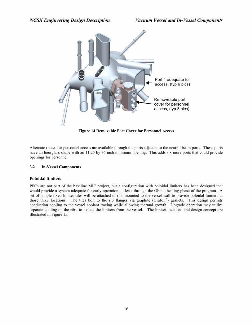
Port access is limited because of the modular coils, PF coils, TF coils, and coil support structure. The three large ports through which the neutral beams are injected have a clear opening of 33 inches tall by 23 inches wide and are adequate for personnel access into the vacuum vessel. Although in the initial configuration only one of the three ports would have neutral beams installed, it is anticipated that ultimately two or perhaps all three would have equipment installed that would block ready access to the vessel interior. For this reason, the port extensions at these locations are now fitted with large rectangular port covers that can be removed even with two neutral beam injectors installed at the same location. This port is illustrated in Figure 14.
NCSX Engineering Design Description Vacuum Vessel and In-Vessel Components
16
Removeable port cover for personnel access, (typ 3 plcs)
Port 4 adequate for access, (typ 6 plcs)
Figure 14 Removable Port Cover for Personnel Access
Alternate routes for personnel access are available through the ports adjacent to the neutral beam ports. These ports have an hourglass shape with an 11.25 by 36 inch minimum opening. This adds six more ports that could provide openings for personnel.
3.2 In-Vessel Components
Poloidal limiters
PFCs are not part of the baseline MIE project, but a configuration with poloidal limiters has been designed that would provide a system adequate for early operation, at least through the Ohmic heating phase of the program. A set of simple fixed limiter tiles will be attached to ribs mounted to the vessel wall to provide poloidal limiters at those three locations. The tiles bolt to the rib flanges via graphite (GrafoilR) gaskets. This design permits conduction cooling to the vessel coolant tracing while allowing thermal growth. Upgrade operation may utilize separate cooling on the ribs, to isolate the limiters from the vessel. The limiter locations and design concept are illustrated in Figure 15.

NCSX Engineering Design Description Vacuum Vessel and In-Vessel Components
17
Plasma
Vessel
Thermal Spacer/Insulator
Weld Stud
Rib
Optional Coolant
Bellville
Threaded Insert
Grafoil Gasket
Tile
Figure 15 Cross-Section of Limiter Concept at VV Field Joints
Internal Contoured Liner
The design is required to accommodate substantial upgrades to the PFCs to meet the requirements for the later stages of the research program, from the Initial Auxiliary Heating Phase onward. To demonstrate that such upgrades are feasible and able to meet requirements, a flexible, re-configurable design concept has been developed. It is a robust concept that can be adapted in its geometrical details and implemented in stages to meet the needs of the research program as it evolves and the detailed requirements are clarified.
The upgrade concept is a contoured liner, one version of which is shown in Figure 16, constructed of molded carbon fiber composite (CFC) panels mounted on a frame of poloidal ribs. When the full complement of panels is installed, they will shield the entire interior surface of the vessel. It is compatible with staged implementation, such that the support structure and the panels can be installed during later operation. During normal operation, the liner will have a lower pre-shot temperature in the range of 40ºC to 150ºC. The molded panels form a continuous shell around the plasma with penetrations for diagnostics, heating, and personnel access. This shell serves many functions. It provides a high heat flux surface in the regions of sharp curvature where the heat flux from the plasma is expected to be highest. It can act as a belt limiter on the inboard midplane. On the lower half of the shell, it will absorb the power deposited by the beam ions that are promptly lost from the plasma. On the outboard side, the shell serves as armor to protect the vacuum vessel and in-vessel components from heat loads due to neutral beam shine-through. The shell also protects in-vessel components mounted on the vessel, e.g., trim coils and magnetic diagnostics, from heat loads from the plasma.

NCSX Engineering Design Description Vacuum Vessel and In-Vessel Components
18
Typical panel(20 types, 90 total)
Panel mounting rib,(one of 18)
Figure 16 Internal Liner with Full Complement of Panels
The continuous shell allows great flexibility in plasma shaping because any surface that the plasma impinges on can act as a limiter and be resistant to damage from plasma heat loads. The properties of the CFC panels can be tailored to the local heat loads if necessary. More expensive panels with high thermal conductivity can be used in limited regions of higher heat loads. Less expensive panels with modest thermal conductivity will be sufficient for most regions.
The panels are attached to 36 multi-section Inconel ribs. The ribs are attached to the vessel via thermally conducting (GrafoilR) gaskets, such that the vessel can provide heating for bakeout and cooling between shots. However, the ribs and/or panels can be traced with independent cooling lines if necessary, in localized areas. They also serve as mechanical isolation members that maintain alignment of the PFC liner during thermal cycling. Figure 17 illustrates the attachment concept for the panels to the ribs. In the present design, the plasma-facing surface is located approximately 3.5 cm from the vacuum vessel surface. This distance will be increased locally to provide room for upgrades such as trim coils, diagnostics, or divertor pumping.

NCSX Engineering Design Description Vacuum Vessel and In-Vessel Components
19
Plasma
PFC
Vessel
1.388.500
Thermal Spacer/Insulator
Weld Stud
Bracket
Optional Coolant Threaded
Insert
Allen Head Shoulder Bolt Retracted Copper
Clip
Flex Clip
Figure 17 Panel-to-Rib Attachment Concept

NCSX Engineering Design Description Vacuum Vessel and In-Vessel Components
20
4 DESIGN BASIS
The design basis for the vacuum vessel includes geometry optimization, design criteria, analysis, and vendor input from manufacturing studies conducted by multiple industrial vendors as part of the conceptual design process.
The design basis for the PFCs includes previous experience, analysis, and vendor input for the molded CFC panels. Because of the close thermal and mechanical interfaces between the VV and PFCs, they have been analyzed in an integrated fashion, including both the initial ohmic operating phases through all the upgrades to the full complement of plasma heating and full coverage of panels.
4.1 Geometry Optimization
The actual geometry of the vessel has been optimized to provide the largest possible envelope that will still allow the modular coils to slide over the vessel sector during field period assembly. Software was developed that provided the maximum “stay-out” zone for a given coil assembly trajectory, then the trajectory was optimized to provide the largest “stay-out” zone4. The vessel geometry was then derived to form a smooth shape within the “stay-out” zone. The basic process is illustrated in Figure 18.
VV cross-section curves
Stay-out -zone Curves curves
Ref plasma shape
vessel shape
Figure 18 Vacuum vessel geometry optimization process
4.2 Design Criteria
The vacuum vessel will be designed according to the NCSX Structural Design Criteria, which is based on the ASME Code, Section VIII, Division 2. The code provides a conservative but prudent approach to design stresses, fatigue, buckling, welding, and inspection of vessels. While the vessel will be designed to be in compliance with the ASME Code, the vessel will not be code-stamped.
4 Brooks, A. and Brown, T, Trajectory of NCSX modular coils and vacuum vessel during field period assembly (Ref. to be provided)

NCSX Engineering Design Description Vacuum Vessel and In-Vessel Components
21
Plasma facing components will also be designed to ASME code type stress limits, although the material properties for carbon fiber reinforced composites (CFC) are not included in the code. The basic material properties for the vessel and PFC materials are listed in Table 5.
Table 5 Material Properties for the VV and PFCs
Material Inconel 625 5
Carbon Fiber Composite
Stackpole 2D 0/90 Material6
Yield strength 55 ksi @ 70ºF (21ºC)
45.7 ksi @ 750ºF (399ºC)
15 ksi (flexural strength)
Ultimate Tensile Strength 110 ksi 8 ksi (in-plane)
Young’s modulus 30 E-6 @ 70ºF
27 E-6 @ 750ºF
4.3 E6 psi
Fatigue strength
(100,000 cycles)
73 ksi base material
39 ksi weld material
70% Sult
Poisson’s ratio 0.28 - 0.30, temp dependent 0.29 (in-plane)
4.3 Vacuum Vessel Structural Analysis
To be provided
4.4 Vacuum Vessel Thermal Analysis
The vacuum vessel temperature is controlled by passing pressurized helium gas through trace lines covering the external surfaces of the shell and with electrical heater strips on the port extensions. During bakeout and standby operation the vessel must be heated and conversely, must be cooled after operational shots. These thermal loading cases are summarized in Table 6. The required repetition rate for all modes of operation is 15 minutes between pulses.
A series of analyses were performed to verify the thermal performance of the NCSX vessel, specifically, to establish the design basis for cooling and heating requirements and coolant supply header design.
• Calculations were performed to determine the heat losses from the vessel as a function of insulation thickness.
• Vessel temperature and cool-down times were determined, based on the operation rep rates, vessel thickness, coolant flow rates, and coolant line clamp spacing.
• Coolant parameters and electrical heater requirements were determined for vessel bakeout and operation. These included electrical heater distribution, tracing pressure drops, flow rates, and temperature change. Tracing variables included the diameter, length, and number of passages.
The Vacuum Vessel System Requirements stipulate that the heating and cooling distribution system and its attachments to the vacuum vessel shell shall be designed to remove 14.4 MJ (assumed to be uniformly spread over the vacuum vessel shell) between pulses. The steady state temperature is not permitted to exceed 100ºC during the cyclic operation.
5 J. Mayhall, “Inconel properties and failure criteria for the ORNL/TFTR RF Antenna Faraday Shield Analysis”, DM-XCS-14690-003, May, 1988 6 A. Brooks “Disruption loads for NCSX Vacuum Vessel FDR design”, April 27, 2004.
NCSX Engineering Design Description Vacuum Vessel and In-Vessel Components
22
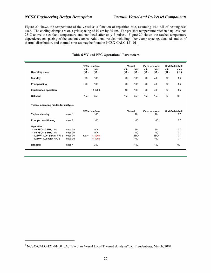
Figure 29 shows the temperature of the vessel as a function of repetition rate, assuming 14.4 MJ of heating was used. The cooling clamps are on a grid spacing of 10 cm by 25 cm. The pre-shot temperature ratcheted up less than 25 C above the coolant temperature and stabilized after only 7 pulses. Figure 20 shows the ratchet temperature dependence on spacing of the coolant clamps. Additional results including other clamp spacing, detailed studies of thermal distribution, and thermal stresses may be found in NCSX-CALC-121-017.
Table 6 VV and PFC Operational Parameters
7 NCSX-CALC-121-01-00_dA, “Vacuum Vessel Local Thermal Analysis”, K. Freudenberg, March, 2004.
min max min max min max min maxOperating state: ( C ) ( C ) ( C ) ( C ) ( C ) ( C ) ( K ) ( K )
Standby 20 100 20 100 20 40 77 85
Pre-operating 20 100 20 100 20 40 77 85
Equilibrated operation < 1200 40 100 20 40 77 85
Bakeout 150 350 150 350 150 150 77 90
Typical operating modes for analysis:
Typical standby: case 1 100 20 20 77
Pre-op / conditioning: case 2 100 100 100 77
Operation: - no PFCs, 3 MW, .3 s case 3a n/a 20 20 77 - no PFCs, 6 MW, .3 s case 3b n/a 100 100 77 - 12 MW, 1.2s, partial PFCs case 3c n/a + < 1200 TBD TBD 77 - 12 MW, 1.2s with PFCs case 3d < 1200 100 100 77
Bakeout: case 4 350 150 150 90
PFCs - surface Vessel VV extensions Mod Coils/shell
Mod Coils/shellPFCs - surface Vessel VV extensions

NCSX Engineering Design Description Vacuum Vessel and In-Vessel Components
23
Figure 19 Thermal Ratcheting of VV Temperature
288
293
298
303
308
313
318
323
328
333
338
343
0 2 4 6 8 10 12
Vertical Spacing Between Cooling Tube Clamps (inches)
Tem
pera
ture
(K)
4 Inch Horizontal Spacing8 Inch Horizontal Spacing8 Inch Horizontal Spacing (30 Minute Cool Down)8 Inch Horizontal Spacing with Chilled He Tubes (T = 273 on pads)
40 C
Figure 20 Racheting Temperature Dependence on Clamp Spacing
Vessel Heat Balance

NCSX Engineering Design Description Vacuum Vessel and In-Vessel Components
24
Table 7, Table 8, and Figure 21 show the results of a study which quantifies the thermal relationships between the vacuum vessel, vessel cooling system, modular coils, cryogenic system, and cryostat under non-operating modes and the effects of various insulation thicknesses on the thermal heat losses. In all cases, the cryostat is assumed to be cooled down to 80 K.
Table 7 Insulation thicknesses assumed in study
Vessel microtherm Cryo foam Backfill insul. Port insul. Path to coil Port coverthickness(cm) thickness(cm) effec. thick.(cm) thickness(cm) (cm) (cm)
Bake 1.27 20.0 15.0 2.54 8.00 1.272 20.0 15.0 5.1 8.00 2.00
2.54 20.0 15.0 5.1 8.00 2.54
Idle 1.27 20.0 15.0 2.54 8.00 1.272 20.0 15.0 5.1 8.00 2.00
2.54 20.0 15.0 5.1 8.00 2.54
Figure 21Vacuum Vessel Heat Balance

NCSX Engineering Design Description Vacuum Vessel and In-Vessel Components
25
Among the interesting results:
• A minimum of 22.4 kW of heating, including electrical, is required to maintain the vacuum vessel and PFCs at 350ºC.
• The cryostat benefits the vessel during cooldown, serving to significantly reduce its coolant load.
• With the cryostat in operation during idle operation, the net load into the vessel coolant is 4.6 kW.
• The cryostat gaseous nitrogen system will require 13.4 kW of cooling during bakeout and 8.1 kW during idle operation.
• The modular coil liquid nitrogen system will require 11.3 kW of cooling during bakeout and 4.5 kW during idle operation
Table 8 Thermal Loads. Rows correspond to insulation thicknesses listed in Table 9.
4.5 Vessel Tracing Thermo-Hydraulic Analysis
4.5.1 Bakeout
The load on the coolant system during bakeout was calculated to determine the flow parameters.
Assumptions:
• 2.5 cm of thermal insulation on vessel external surface
• 2 cm average around the ports
• 15 cm average fill between the shell and vessel wall to thermally isolate the modular coils.
Vessel Port Cover Vessel to coilVessel to Cryo Cryo inleak Vessel to Coil to ambient sides Port to Cryo Vessel Coolant
Qt Qv front Qc Qa Qci Qp QnkW kW kW kW kW kW kW
Bake 0.3 3.3 17.2 1.9 2.7 19.5 -30.020.3 3.3 10.9 1.2 2.7 9.75 -19.130.3 3.3 8.6 1.0 2.7 9.75 -16.54
Idle 0.1 3.3 6.8 0.0 1.1 9.4 -8.060.1 3.3 4.3 0.0 1.1 4.7 -5.550.1 3.3 3.4 0.0 1.1 4.7 -4.63
LN2 consumptionexterior heating
port extension heating
Total Coil Coolant Load
Total (gas and liquid) Cryo system load
(l/hr) (kW) (kW) (kW) (kW)Bake 973 2.51 -11.7 20 43.42
611 2.51 -5.85 13.7 27.1559 2.51 -5.85 11.4 24.8
Idle 467 2.51 -9.28 7.8 20.7305 2.51 -4.64 5.4 13.5285 2.51 -4.64 4.5 12.6

NCSX Engineering Design Description Vacuum Vessel and In-Vessel Components
26
• 5.5.m tracing length per circuit
• 192 parallel circuits
• port heaters supply 5.9 kW
• efficiency of 75%
• loss of 16.5 kW from the liner to the cryostat (80 K) and Modular Coils
Results
• Helium at 20 atmospheres and inlet temperature of 362 C.
• 5/16 inch OD, 0.256 inch ID tubing (0.65 cm ID)
• Helium inlet velocity 30 m/s
• Total maximum mass flow to liner 1040 kg/hr (407 cfm )
• Pressure drop 0.19 atmospheres,
The pressure drop is very nominal and the velocity differential between tracings is only 19% so flow balancing will not be a concern. However, every effort will be made to keep the runs approximately equal in length. Analysis for 15 minute cool down times between shots indicate that the heating lines have more than ample capacity. The final temperature is not sensitive to flow parameters, as the liner is conduction limited. More detailed information, including flow distribution in individual tracing lines may be referenced in NCSX-CALC-121-02 8.
If 350ºC bakeout proves difficult or takes excessive time, it is possible to augment the gas heating with the electrical resistance strip heaters wrapped around the ports. There is also excess capacity available in the tracing design; and it could be upgraded to supply 27 kW. Adding significant additional insulation is not a practical solution since most of the available space has already been utilized, i.e. the fit between the vessel, ports, shell, and modular coils limits insulation.
4.5.2 Cooldown between Pulses
Analysis was done using the same geometry and insulation assumptions as above, but with 14.4 MJ of heat being removed in 15 minutes and 4.7 kW of resistance heating applied to the ports.
Results
• Helium at 20 atmospheres and inlet temperature of 20ºC.
• Helium inlet velocity 30 m/s
• Total maximum mass flow to liner 2200 kg/hr (407 cfm )
• Pressure drop 0.29 atmospheres,
• Average temperature rise in Helium 5 C
It is clear that the flow could be reduced during early lower power operation, to reduce the horsepower requirement of the system.
4.5.3 Port Extension Resistance Heaters
During bakeout the port electrical heaters will have to supply on the order of 5.9 kW. During idle [pre-shot] operation this value drops to 4.7 kW. The port extensions need to have heat distributed evenly along their length, particularly during operation. Figure 22 shows the temperature distribution during bakeout of a typical port. Models representing heat added along the outer half of the extensions show portions of the pipe running well below
8 NCSX-CALC-121-02, “NCSX Vacuum Vessel Heating/Cooling Distribution System Thermo-hydraulic Analysis”, P. Goranson, March, 2004.

NCSX Engineering Design Description Vacuum Vessel and In-Vessel Components
27
room temperature [-15 C]. Attempts to boost the temperatures up to the required pre-shot temperature of 20ºC results in very high temperatures at the port flanges. With heat added at the midway point, portions of the pipe run hot [102ºC] and exceed the maximum permitted pre-shot operation temperature of 40ºC. Total port coverage will make replacement of heaters very difficult or impossible since there is no access to the entire length of the extension once the vessel is assembled. The recommended solution is to add redundant heaters to the ports. The heaters will be enclosed by a copper mesh or foil wrap that will aid in distributing the heat and have the additional function of shunting heat out to the cryostat in the event there are hot spots on the port extensions caused by thin insulation. This is a condition that could otherwise excessively load the modular coils. Internal heaters can be added inside the port on the vacuum side in the event both the primary and secondary heaters are lost.
The analysis performed to date is strictly a global overview of the heat balance mechanisms at work in the vessel system; it is based on simple area/conduction relationships assuming perfect contact between components such as the modular coils and vessel and ignores details of the local geometry. It is meant as a first cut for design purposes and is useful for bounding the insulation requirements, power requirements, and tracing coolant parameters. It will be followed up by 3-D finite NASTRAN models which will more closely represent the actual geometry.
Ports have been added to the vessel since this analysis and the total heat input to the ports will increase; total heat input to the vessel wall will decrease. The net energy input should not change markedly.
HEATED PORT TEMPERATURE DISTRIBUTIONBakeout at 350 C
0.00
100.00
200.00
300.00
400.00
500.00
600.00
700.00
0 5 10 15 20 25
PORT ELEMENT (5 cm each)
POR
T TE
MPE
RA
TUR
E (K
)
VV
portflange
Heat distributed evenly
Figure 22 Heat Distribution On 8 Inch Port With 65 Watt Heater

NCSX Engineering Design Description Vacuum Vessel and In-Vessel Components
28
HEATED PORT TEMPERATURE DISTRIBUTION Operation at room temperature
250.00
255.00
260.00
265.00
270.00
275.00
280.00
285.00
290.00
295.00
300.00
0 5 10 15 20 25
PORT ELEMENT (5 cm each)
PO
RT
TEM
PER
ATU
RE
(K)
port flgVV
Heat distributed evenly
Figure 23 Heat Distribution On 8 Inch Port With 54 Watt Heater

NCSX Engineering Design Description Vacuum Vessel and In-Vessel Components
29
5 DESIGN IMPLEMENTATION
5.1 Manufacturing Studies and In-house R&D
In order to obtain feedback from potential fabricators concerning the feasibility, methods, and cost for fabricating the vacuum vessel, funded manufacturing studies of the NCSX vessel were performed by five capable suppliers. The studies were based on a set of CAD models and a draft procurement specification. The vendors proposed several methods for forming the vessel, including hot pressing, cold pressing, explosive forming, and casting. Several suggestions were made concerning details such as port reinforcement design, spacer design, assembly flange design, etc. All the vendors recommended some R&D, but all concluded that the vessel shape, tolerances, and other requirements were feasible. Input was obtained from a potential vendor concerning the large PFC panels, which are not part of the baseline project but will be required as an upgrade during later phases of operation. The approximate size limitations and processing data were discussed. The panels are feasible using commercial pressing and infiltration processes.
A critical feature of the vacuum vessel design is the welded assembly joint between the three vessel field period segments. As described in Section 2, a spacer will be provided between sectors to provide adjustment for proper fit-up. However, the ability to make the welds successfully from inside the vessel with minimal distortion and no damage to the modular coils must be demonstrated in advance. The present plan is to mock up the field joint in two stages. The first stage will consist of small weld coupons to determine the best joint geometry for welding from one side. The second stage will consist of full scale mockups of the weld region, including the 25 degree joint angle but not prototypical contour geometry. Prototypical weld joint flanges will be welded to these mockups and machined for proper fit. The sectors will be welded from inside and the temperature and distortion measurements will be recorded. If further refinement to the joint is still necessary, the sectors can be cut and re-welded.
5.2 Manufacturing Development and Prototype Fabrication
In order to qualify vendors prior to contracting for the final vessel, two separate R&D contracts were awarded to establish the feasibility of proposed fabrication processes and to guide the design team toward the optimum design for the selected process. The process under consideration is press forming. The feasibility of the press forming and welding is not an issue, but some R&D is suggested to establish forming parameters for the Inconel in the 0.375 inch thickness, and for verifying the number of panels needed for a complete half period of the vessel. In addition, the welding of a port extension into the vessel torus from inside the vessel must be demonstrated to verify the welding equipment requirements, identify fixturing, and finalize the design details for the joint.
To date, the vendors have provided detailed manufacturing plans and cost estimates, and have completed or have nearly completed fabrication of a partial, full scale prototype of a section of the vessel. The prototype is shown in Figure 24. The intent of the prototype is to demonstrate all the critical processes, including forming, welding, geometric inspection, and leak checking in a single article. The two prototype sectors, one from each vendor, will also be used at PPPL to validate the inspection processes and could be used to practice port welding during field period assembly.

NCSX Engineering Design Description Vacuum Vessel and In-Vessel Components
30
Figure 24 Prototype Vacuum Vessel Segment (PVVS)
5.3 Component Procurement and Fabrication
Three vacuum vessel sub-assemblies will be procured via a fixed price subcontract, including the supply of all required labor and materials, machining, fabrication, and factory acceptance inspections and tests. The vacuum vessel sub-assemblies delivered to the Princeton Plasma Physics Laboratory (PPPL) site will include three field period subassemblies, the (unattached) port extensions, and spacers.
The vacuum vessel insulation, coolant tracing, supports, local I&C, and neutral beam transition ducts will be separately procured,
5.4 Vacuum Vessel and Field Period Assembly
The vacuum vessel will be provided in three identical sections, corresponding to field periods of the magnetic configuration. Trace lines will be added to the exterior of the vessel at PPPL. Six modular coils and six TF coils will be assembled over one field period of the vessel along with the coil support structure. The vessel port extensions will then be welded in place. The trace lines will be connected to the headers at the top and bottom of the large central port extensions. After these connections are leak checked, the thermal insulation will be applied all the port extensions. At this point the vessel field period ends will be sealed with cover plates. The vessel will be baked to 375C and leak checked and any repairs made to the port extension welds.

NCSX Engineering Design Description Vacuum Vessel and In-Vessel Components
31
6 RELIABILITY, MAINTAINABILITY, AND SAFETY
The reliability of the vacuum vessel is critical to the operation of NCSX. Once the vessel is installed, there is essentially no access to the outer surfaces for inspection or maintenance, and limited access to the interior surfaces of the vessel. To ensure adequate margin against failures, the vessel will be designed in accordance with the rules of the ASME Boiler and Pressure Vessel Code, Section VIII, Division II and fabricated in strict conformance with an approved manufacturing, inspection and test plan. Numerous quality checks will be performed during subsequent assembly and installation operations.
A primary issue is vacuum leaks. The first step is to find and repair incipient leaks prior to final assembly. To this end, the vessel will be thermally cycled above the bakeout temperature and leak checked at the vendor and at the field period assembly level to ensure that all welds are robust against leaking due to thermal excursions. To facilitate leak checking of the port re-attachment welds during field period assembly, each welded joint will include a seal ring and gas line that will allow the introduction of helium around the exterior perimeter of each these weld joints. With the vessel under vacuum, each weld joint can be helium leak checked individually. Finally, the field welds between the vessel shell sectors must also be leak checked, so each of these welds will also have a seal ring and gas feed.
In the event of a modular coil failure or vessel leak that cannot be isolated, the vessel must be capable of being cut apart at the field joints so the field period subassemblies can be simultaneously retracted in the radial direction. No special features are included for the purpose of cutting, but the gas seal would help prevent heat, metallic debris or other contamination from migrating outside the vessel during the cutting operation.

NCSX Engineering Design Description Vacuum Vessel and In-Vessel Components
32
7 COST AND SCHEDULE
To be provided at the FDR

NCSX Engineering Design Description Vacuum Vessel and In-Vessel Components
33
8 RISK MANAGEMENT
8.1 PFCs
The primary technical risks associated with the PFC system are 1) damage to the first wall or vessel from excessive heat flux and 2) excessive impurity influx to the plasma. These problems may arise due to lack of proper materials in the high heat flux regions and/or insufficient wall conditioning or bakeout temperatures to remove wall impurities. In stellarators, it is difficult to predict with certainty where the high heat flux regions will be, and these regions will move with different magnetic configurations. To mitigate these concerns, the PFC system has been designed to allow coverage of the entire interior surface of the vessel with CFC armor. Graphite and CFC tiles have been used successfully on most of the fusion experiments worldwide, and can tolerate extreme heat flux and thermal shock without failure. However, these materials must be baked at temperatures in excess of 300ºC. For that reason, NCSX initially designed the PFC system to be supported from a rib structure inside the vacuum vessel that could be heated to 350ºC while the vessel was maintained at 150ºC. This is the approach used successfully on NSTX. However, for NCSX this requires an elaborate system of interior cooling and thermal isolators. The project has decided during final design, based on a recommendation from the preliminary design review, to bake the vessel shell to 350ºC, and heat sink the interior PFCs to the vessel wall. The port extension will be allowed to transition in temperature from 350ºC to 150ºC at the first flange. This provides the high temperature necessary to condition the PFCs while maintaining the ports at 150ºC to minimize engineering problems of the viewing windows and diagnostics.
8.2 Vacuum vessel
The vacuum vessel has potential technical, cost and schedule risks. The technical risks can be listed, as well as the mitigation plan:
The vessel may not permit a high quality vacuum (leaks, outgassing, etc.)
The first potential risk, that the vessel will not permit a high quality vacuum, is addressed in the design, the procurement specification, and the manufacturing, inspection, and test plan. The vessel will have the minimum number of welds consistent with the fabrication technique. The welds will be full penetration with a GTAW root pass and GTAW or GMAW filler passes, with no SMAW welding permitted. The vessel will be leak checked at the fabricator after multiple heating and cooling cycles. The interior surfaces will be polished and cleaned according to accepted vacuum equipment standards. The main assembly flanges between field periods will be welded with full penetration welds. The large, irregular shaped ports will have double seals, with differential pumping between the seals. The NBI port will have metal seals, due to its close proximity to the vessel shell. All the circular ports will have Conflat seals. In addition to leak checking at the manufacturer, leak checking will occur after the port extensions are welded in place and prior to assembly of the three field periods. Each port and each main assembly joint will have shielding gas sleeves fitted outside the weld seams. Gas lines will be fitted to each of these to provide a method for isolating any leaks to a particular weld joint.
The vessel may not have the correct shape
The second potential risk, that the vessel will not have the correct shape, is mitigated by the 3-D CAD technology and the use of modern 3-D measurement equipment such as laser trackers and portable coordinate measurement systems. The vessel can be continuously measured and corrections made during the fabrication process, and intermediate heat treatment will be provided to reduce residual stresses that could cause distortion during operation. All the fabrication processes will be demonstrated and optimized during the R&D phase of the vessel procurement, where full scale, partial prototypes will be fabricated and measured. A spacer is included between each field period subassembly that can be custom-machined to accommodate any misalignment between field period assembly flanges.
NCSX Engineering Design Description Vacuum Vessel and In-Vessel Components
34
The coils will not fit over the vessel
The third potential risk, that the vessel will not fit inside the modular coils, is also mitigated by the 3-D CAD technology, the use of laser scanners and/or multilink measuring systems to verify geometry, and using accurate scale models of the vessel and coils during the design and development processes. A 1/12 scale model of the present design verifies that the coils and vacuum vessel can be assembled as planned. In addition, software has been developed to optimize the coil assembly trajectory over the vessel. Using this trajectory with the Pro/Engineer CAD package offers another way to detect possible interferences and to quantify clearances throughout the assembly process. As the components are fabricated, as-built geometry can be used for the CAD models.
The vessel may fail mechanically
The fourth potential risk, that the vessel will fail mechanically, is mitigated by analysis and conservative design criteria. Critical analysis, such as disruption load calculations, stress and deflection calculations and buckling analysis will be performed by independent groups using different codes and models. The disruption loads are relatively small compared to a tokamak of similar size, so these are not expected to cause significant problems. The stresses will be compared to the ASME code allowables, which provide a safety factor of 1.5 on yield for primary membrane stresses at the operating temperature.
The vessel may not have adequate thermal performance
The fifth potential risk, that the vessel will not have adequate thermal performance, is mitigated by using the same temperature control system successfully used for the NSTX vessel. The system is designed to provide twice the heating capability and eight times the cooling capability predicted by analysis. Multiple redundant paths ensure that minor blockages or minor leaks will not affect overall performance.
The vessel may introduce static or transient field errors
The sixth potential risk, that the vessel will introduce field errors, is mitigated by the choice of material and the strict adherence to stellarator symmetry. The material, Inconel 625, has a relatively high electrical resistivity, about 50% higher than 300 series stainless steel. This results in an electrical time constant of less than 10 ms for the most persistent induced current path. In addition, the relative magnetic permeability of the material, even after forming and welding is very low, less than 1.01, so field errors due to induced magnetism should be negligible. Finally, the port locations and geometry are stellarator-symmetric, so any currents that are induced in the vessel should also be stellarator-symmetric.
The vessel will not permit sufficient access for inspection, maintenance, or reconfiguration of internal components
The seventh potential risk, that the vessel will not permit sufficient access for maintenance and reconfiguration of internal components, is mitigated by providing as many ports as possible that are large enough for manned access. The three neutral beam locations each have a 14 x 33 inch oblong port that is accessible even with the beams installed. On either side of the neutral beam port are hourglass shaped ports with an 11.25 inch minimum width and 36 inch height, providing a total of six more manned access ports. Finally, the large neutral beam port cover flanges can be removed in at least one location to provide a clear, diamond shaped opening of 28 x 38 inches.
Cost and schedule risks
The cost and schedule risks associated with the vacuum vessel could also be significant, but steps have been and are being taken to reduce those risks substantially. Manufacturing studies were carried out during the conceptual design process to obtain advice from manufacturing engineers on ways to make the design easier or less expensive to fabricate. Five different studies of the vessel were carried out, and several fabrication processes were considered, including hot pressing, cold pressing, explosive forming, and casting. Vendor input has been continued throughout the preliminary and final design phases with an extensive R&D program. Two different vendors have fabricated partial prototypes of critical regions of the vessel. The forming, welding, machining, polishing, and inspection processes have all been demonstrated and optimized. At the conclusion of the R&D phase, a fixed price contract

NCSX Engineering Design Description Vacuum Vessel and In-Vessel Components
35
will be awarded for the production vessel. Having two vendors participate in the prototype fabrication phase will result in at least two qualified vendors for the production articles, and provides an extra incentive to keep production costs (and bids) low.