Multi-Objective Design of the Rotor System - NREL · PDF fileparameter/constraint changes such...
20
NREL Wind Energy Systems Engineering Workshop January 14-15, 2015 - Boulder, Colorado Kristian Dixon, M.Sc. Multi-Objective Design of the Rotor System
Transcript of Multi-Objective Design of the Rotor System - NREL · PDF fileparameter/constraint changes such...

NREL Wind Energy Systems Engineering Workshop January 14-15, 2015 - Boulder, Colorado Kristian Dixon, M.Sc.
Multi-Objective Design of the Rotor System

NREL Wind Energy Systems Engineering Workshop 2015 Copyright © 2015 Siemens Energy, Inc. 2
Agenda
• Recap: the rotor design problem
• Recap: SWP rotor optimization process
• Application of MDO: Analysis of a design space by comparison of different technology (Pareto) fronts for changing system constraints
• Example: NREL 5MW rotor design problem
• Technical challenges of industrial MDO application
• Conclusions

NREL Wind Energy Systems Engineering Workshop 2015 Copyright © 2015 Siemens Energy, Inc. 3
How to minimize total COE? Accurate cost modelling • Many disciplines, complex, coupled system, many aspects are unpredictable
• Cost model that combines various sub-disciplines may not be desirable – many ‘costs’ cannot be estimated up-front (i.e. organizational cost, market ‘fit ’ etc.) or there is insufficient data to construct a meaningful model useful for optimization
• Simplify – solve the problem using a multi-objective approach – give decision-makers the data necessary to make trade-off choices directly including ‘non-quantifiable’ costs
Recap: Multi-Disciplinary Rotor Design Optimization
• engineering
• admin
• BOM
• manufacturing
• transport & construction
• service
• balance of station
• financing
NREL Wind Energy Systems Engineering Workshop 2015 Copyright © 2015 Siemens Energy, Inc. 4
Recap: Multi-Disciplinary Rotor Design Optimization
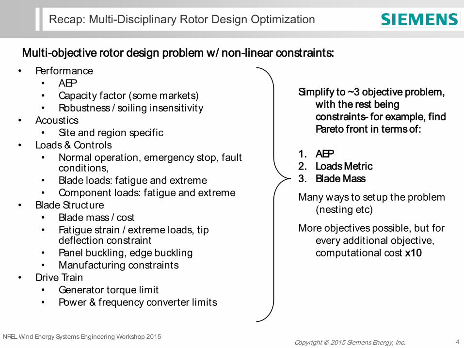
• Performance • AEP • Capacity factor (some markets) • Robustness / soiling insensitivity
• Acoustics • Site and region specific
• Loads & Controls • Normal operation, emergency stop, fault
conditions, • Blade loads: fatigue and extreme • Component loads: fatigue and extreme
• Blade Structure • Blade mass / cost • Fatigue strain / extreme loads, tip
deflection constraint • Panel buckling, edge buckling • Manufacturing constraints
• Drive Train • Generator torque limit • Power & frequency converter limits
Simplify to ~3 objective problem, with the rest being constraints- for example, find Pareto front in terms of:
1. AEP 2. Loads Metric 3. Blade Mass
Many ways to setup the problem (nesting etc)
More objectives possible, but for every additional objective, computational cost x10
Multi-objective rotor design problem w/ non-linear constraints:

NREL Wind Energy Systems Engineering Workshop 2015 Copyright © 2015 Siemens Energy, Inc. 5
Recap: Technology Front / Multi-Objective Pareto Fronts
Objective 1
Objective 2 dominated
non dominated
A
Objective 1
Objective 2
A
technology fronts not always continuous
A Pareto front gives the set of best possible trade-offs between objectives
example: 3 objective front
minimize objective 1 and 2

NREL Wind Energy Systems Engineering Workshop 2015 Copyright © 2015 Siemens Energy, Inc. 6
Recap: SWP Rotor Optimization Process
Siemens Blade Optimization Tool (SBOpT) + Galapagos GA Optimizer
• Evaluates 500,000+ blades in an evening within Galapagos and HPC cluster, produces N-dimensional Pareto front between various design objectives
BHawC
• FE code for aero-elastic simulation of entire turbine system
SBOpT +
Galapagos product
specification candidate selection
and finishing
BHawC
hi-fi structural modelling/design
feedback/tuning
feedback/tuning
technology front
structural iteration
final product

NREL Wind Energy Systems Engineering Workshop 2015 Copyright © 2015 Siemens Energy, Inc. 7
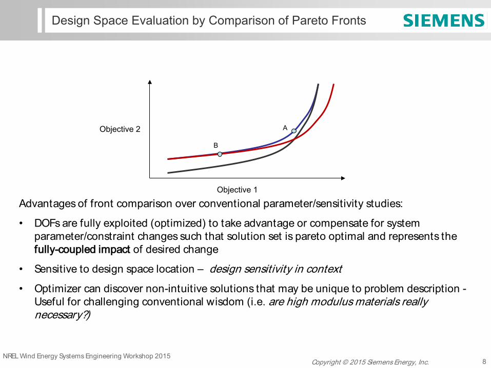
Design Space Evaluation by Comparison of Pareto Fronts
• Parameter studies about a fixed planform can only go so far…
• Instead, it ’s desirable to assess the multi-objective impact of various system constraints / parameters in a way that takes advantage of full design freedom that is available
• Compare Pareto fronts generated for slightly different problems (i.e. constraints, technology assumptions etc.)
• Noise
• Soiling sensitivity
• Allowable tip deflection
• Blade structural technology / material choice
• Component load constraints
• Airfoil selection
• Rated power / rated torque
• Wind resource
• Design for manufacture
• Transportation
• Cost and many others…
NREL Wind Energy Systems Engineering Workshop 2015 Copyright © 2015 Siemens Energy, Inc.
Advantages of front comparison over conventional parameter/sensitivity studies:
• DOFs are fully exploited (optimized) to take advantage or compensate for system parameter/constraint changes such that solution set is pareto optimal and represents the fully-coupled impact of desired change
• Sensitive to design space location – design sensitivity in context
• Optimizer can discover non-intuitive solutions that may be unique to problem description - Useful for challenging conventional wisdom (i.e. are high modulus materials really necessary?)
8
Design Space Evaluation by Comparison of Pareto Fronts
Objective 1
Objective 2 A
B

NREL Wind Energy Systems Engineering Workshop 2015 Copyright © 2015 Siemens Energy, Inc. 9
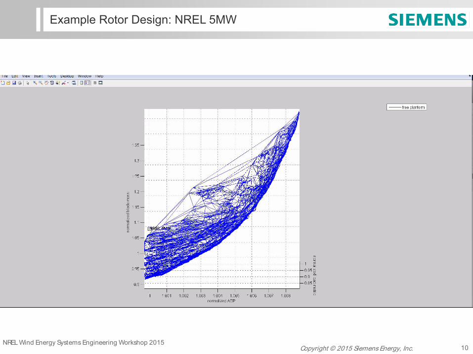
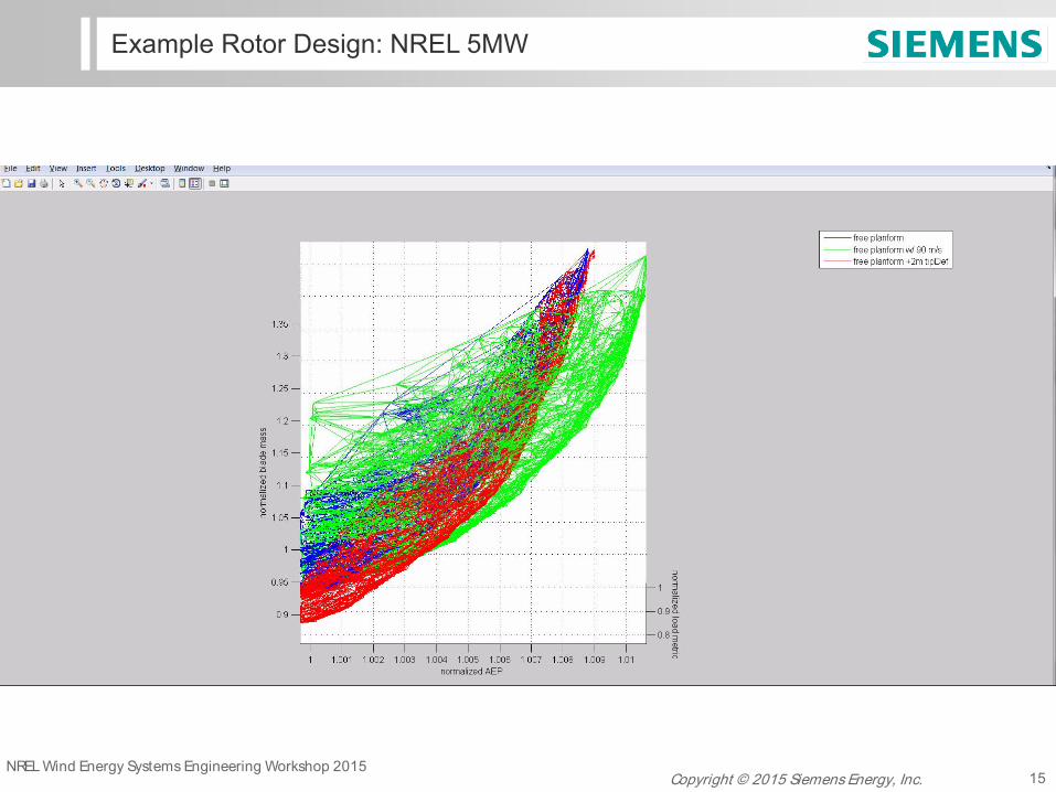
Example Rotor Design: NREL 5MW
• NREL 5MW rotor as described in NREL/TP-500-38060 http://www.nrel.gov/docs/fy09osti/38060.pdf J. Jonkman et. al.
• Spanwise distributions of relative thickness, twist and chord treated as free DOFs
• All other turbine parameters left as-is.
• 1A wind resource
• NREL 5MW evaluated using SWP Integral Blade™ structural technology
Blad
e m
ass
(nor
mal
ized
)
Max gust load metric (normalized)
AEP (normalized)
NREL Wind Energy Systems Engineering Workshop 2015 Copyright © 2015 Siemens Energy, Inc. 10
Example Rotor Design: NREL 5MW

NREL Wind Energy Systems Engineering Workshop 2015 Copyright © 2015 Siemens Energy, Inc. 11
Comparison NREL 5MW Technology Fronts
• 80m/s vs. 90 m/s maximum tip speed planform design Pareto (technology) fronts
100 100.1 100.2 100.3 100.4 100.5 100.6 100.7 100.8 100.990
95
100
105
110
115
120
125
130
135
AEP (normalized to NREL 5MW)
blad
e m
ass
(nor
mal
ized
to N
REL
5M
W)
Tech Front Slice at Constant 90 % NREL 5MW Max Gust Load
NREL 5MW
planform optimization w/ max tip speed of 80 m/splanform optimization w/ max tip speed of 90 m/s
90 m/s max tip speed shrinks region 2.5 – better overall aero performance; Differences only significant for high mass / high load blades Trade-off for low mass/low load blade is lower outboard solidity, and less able to take advantage of higher tip speed
Slicing plane @ 90% of NREL 5MW load metric
mas
s
loads
NREL Wind Energy Systems Engineering Workshop 2015 Copyright © 2015 Siemens Energy, Inc. 12
Comparison NREL 5MW Technology Fronts
100 100.1 100.2 100.3 100.4 100.5 100.6 100.7
95
100
105
110
115
120
125
130
AEP (normalized to NREL 5MW)
blad
e m
ass
(nor
mal
ized
to N
REL
5M
W)
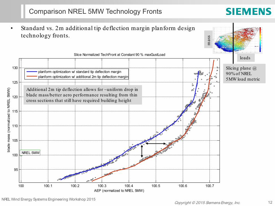
Slice Normalized TechFront at Constant 90 % maxGustLoad
NREL 5MW
planform optimization w/ standard tip deflection marginplanform optimization w/ additional 2m tip deflection margin
Additional 2m tip deflection allows for ~uniform drop in blade mass/better aero performance resulting from thin cross sections that still have required building height
• Standard vs. 2m additional tip deflection margin planform design technology fronts.
Slicing plane @ 90% of NREL 5MW load metric
mas
s
loads
NREL Wind Energy Systems Engineering Workshop 2015 Copyright © 2015 Siemens Energy, Inc. 13
Comparison NREL 5MW Technology Fronts
100 100.1 100.2 100.3 100.4 100.5 100.6 100.7 100.8 100.990
95
100
105
110
115
120
125
130
135
AEP (normalized to NREL 5MW)
blad
e m
ass
(nor
mal
ized
to N
REL
5M
W)
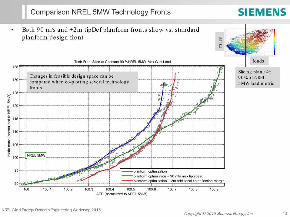
Tech Front Slice at Constant 90 %NREL 5MW Max Gust Load
NREL 5MW
planform optimizationplanform optmization + 90 m/s max tip speedplanform optimization + 2m additional tip deflection margin
Changes in feasible design space can be compared when co-plotting several technology fronts
• Both 90 m/s and +2m tipDef planform fronts show vs. standard planform design front
Slicing plane @ 90% of NREL 5MW load metric
mas
s
loads
NREL Wind Energy Systems Engineering Workshop 2015 Copyright © 2015 Siemens Energy, Inc. 14
Comparison NREL 5MW Technology Fronts
100 100.1 100.2 100.3 100.4 100.5 100.680
82
84
86
88
90
92
94
96
98
100
AEP (normalized to NREL 5MW)
max
gus
t loa
d (
(nor
mal
ized
to N
REL
5M
W))
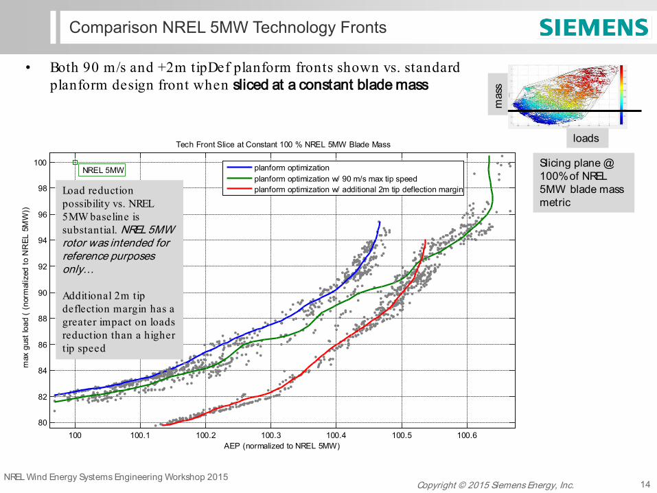
Tech Front Slice at Constant 100 % NREL 5MW Blade Mass
NREL 5MW
planform optimizationplanform optimization w/ 90 m/s max tip speedplanform optimization w/ additional 2m tip deflection marginLoad reduction
possibility vs. NREL 5MW baseline is substantial. NREL 5MW rotor was intended for reference purposes only… Additional 2m tip deflection margin has a greater impact on loads reduction than a higher tip speed
• Both 90 m/s and +2m tipDef planform fronts shown vs. standard planform design front when sliced at a constant blade mass
Slicing plane @ 100% of NREL 5MW blade mass metric
mas
s
loads
NREL Wind Energy Systems Engineering Workshop 2015 Copyright © 2015 Siemens Energy, Inc. 15
Example Rotor Design: NREL 5MW

NREL Wind Energy Systems Engineering Workshop 2015 Copyright © 2015 Siemens Energy, Inc. 16
Technical Challenges of MDO
• Speed vs. fidelity trade-off OR cycle time vs. confidence level
• Maximizing engineering iterations <1 day cycle time
• Accurate load analogs – full IEC load calculations are time consuming, how can we get 90% of this information for 10% of the computation time?
• Software architecture – working with legacy codes that were not designed with optimization in mind. IT/software challenges often are not fully appreciated. The higher the fidelity of models used, the more this issue is magnified
model fidelity
comp. cost
useful for optimization mixed/medium fidelity doesn’t always exist
analytical solutions ?
most legacy codes most experienced people design by analysis
NREL Wind Energy Systems Engineering Workshop 2015 Copyright © 2015 Siemens Energy, Inc. 17
Conclusions and Final Thoughts
• The technique of Pareto front comparison has been demonstrated for an example NREL 5MW design space
• Pareto front comparison is useful for evaluating fully coupled impact of technology changes / system parameters on rotor design
• Expert knowledge can be used to inform/tune low and medium fidelity models that make wide ranging design space exploration and exploitation possible in a practical timeframe
• Avoid the rushing immediately to complex models/systems until lower fidelity representations have been exhausted especially when doing optimization
• MDO techniques are not push button – communication and expectations must be managed carefully
• Potential of SE for COE reduction is significant!
NREL Wind Energy Systems Engineering Workshop 2015 Copyright © 2015 Siemens Energy, Inc. 18 of 12
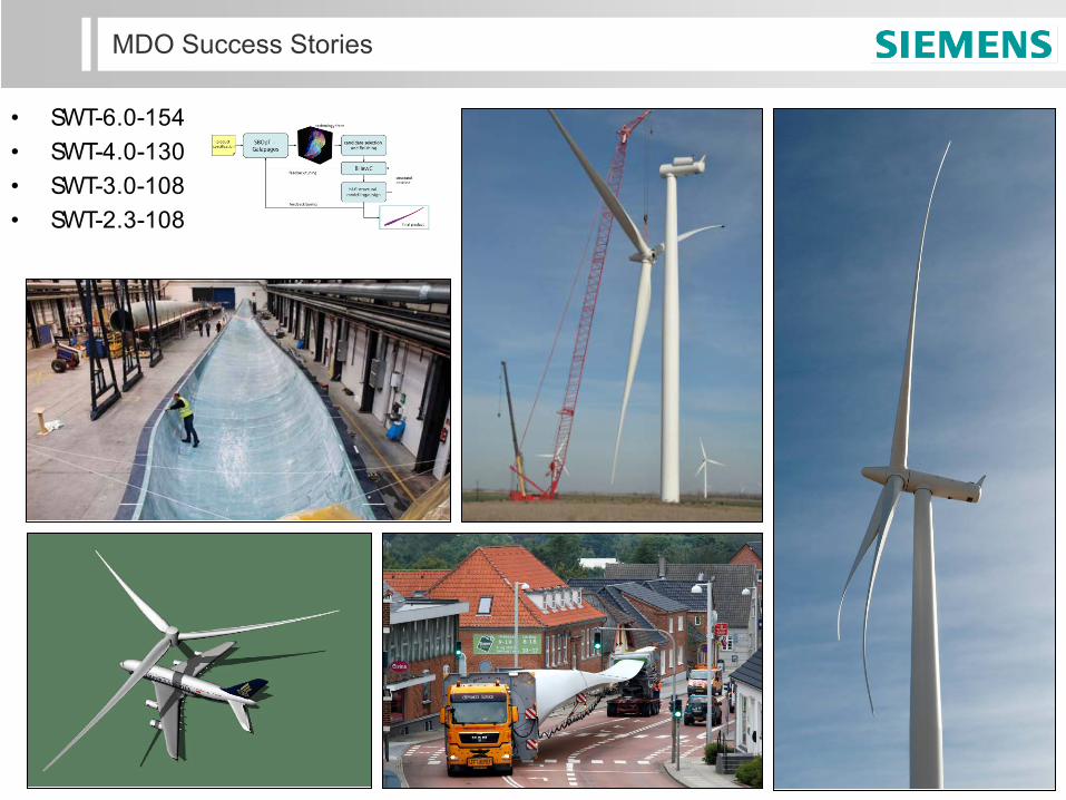
MDO Success Stories
• SWT-6.0-154 • SWT-4.0-130 • SWT-3.0-108 • SWT-2.3-108

NREL Wind Energy Systems Engineering Workshop 2015 Copyright © 2015 Siemens Energy, Inc. 19 of 12
Thanks for your attention - Questions?
contact: [email protected]
NREL Wind Energy Systems Engineering Workshop 2015 Copyright © 2015 Siemens Energy, Inc. 20
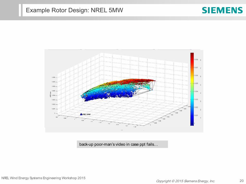
Example Rotor Design: NREL 5MW
back-up poor-man’s video in case ppt fails…