MTG Proof of Concept Functional Requirements - Ohio.gov
39
Ohio Department of Commerce: Elevator Inspection Proof of Concept Functional Requirements Specification 1.0 June 22nd, 2004 Real People Real Solutions Real Results
Transcript of MTG Proof of Concept Functional Requirements - Ohio.gov

Ohio Department of Commerce:
Elevator Inspection Proof of Concept Functional Requirements Specification 1.0
June 22nd, 2004
Real People Real Solutions Real Results

Table of contents: OHIO DEPARTMENT OF COMMERCE: .............................................................................................. 1 ELEVATOR INSPECTION PROOF OF CONCEPT .............................................................................. 1
FUNCTIONAL REQUIREMENTS SPECIFICATION 1.0.................................................................................. 1 1. HIGH LEVEL OVERVIEW:.................................................................................................................. 4
1.1 GENERAL DESCRIPTION:....................................................................................................................... 4 1.2 OBJECTIVES .......................................................................................................................................... 4 1.3 REFINED PROJECT SCOPE...................................................................................................................... 5
1.3.1 Key Deliverables.......................................................................................................................... 5 1.3.2 High-Level Design Assumptions .................................................................................................. 5
2. PROCESS FLOWS .................................................................................................................................. 6 2.1 ELEVATOR INSPECTION PROOF OF CONCEPT PROCESS FLOW ............................................................... 6
3. USE CASES .............................................................................................................................................. 7 3.1 ACTORS ................................................................................................................................................ 7 3.2 USE CASE DESCRIPTIONS...................................................................................................................... 8
3.2.1 Use case description .................................................................................................................... 8 3.2.2 Events........................................................................................................................................... 9
3.3 BUSINESS EVENTS .........................................................................ERROR! BOOKMARK NOT DEFINED. 3.4 USE CASE ASSOCIATION DIAGRAM .................................................................................................... 10 3.5 USE CASES.......................................................................................................................................... 11
3.5.1 Use Case Authenticate User ...................................................................................................... 11 3.5.2 Use Case Login to Web Application .......................................................................................... 13 3.5.3 Use Case Login to Smart Client Application ............................................................................. 15 3.5.4 Use Case Logout Smart Client Application ............................................................................... 17 3.5.5 Use Case Logout Web................................................................................................................ 19 3.5.6 Use Case Modify Job Ticket....................................................................................................... 20 3.5.7 Use Case Smart Client Send Job Ticket ..................................................................................... 22 3.5.8 Use Case Smart Client Receive Job Tickets............................................................................... 24 3.5.9 Use Case Process Job Ticket Update......................................................................................... 26 3.5.10 Use Case Reconcile Data in Conflict....................................................................................... 28 3.5.11 Use Case View Job Ticket List on Smart Client....................................................................... 30 3.5.12 Use Case View Job Ticket List via Web ................................................................................... 31 3.5.13 Use Case View Job Ticket via Web .......................................................................................... 32
4. HIGH LEVEL APPLICATION ARCHITECTURE .......................................................................... 33 5. USER INTERFACES............................................................................................................................. 34
5.1.1 Web Screens ............................................................................................................................... 34 5.1.2 Smart Client Screens.................................................................................................................. 36
6. ENVIRONMENT ................................................................................................................................... 38 6.1.1 Hardware:.................................................................................................................................. 38 6.1.2 Server Software:......................................................................................................................... 38 6.1.3 Development Software ............................................................................................................... 38 6.1.4 Client.......................................................................................................................................... 38 6.1.5 Special........................................................................................................................................ 38
APPENDIX A: SIGN-OFF ....................................................................................................................... 39

Change History Date Personnel Description Version
6/7/2004 Stephen J. Webb (ICC) Initial Version 0.1
6/21/2004 Stephen J. Webb (ICC) Added Screenshots 0.2
6/22/2004 Stephen J. Webb (ICC) Final Version 1.0

Mobile Transaction Gateway Version 1.0 Elevator Inspection Proof of Concept Issue Date: 4/12/2006
Confidential Information Control Corporation
Page 4 of 39
1. High Level Overview:
1.1 General Description: The Ohio Department of Administrative Services Information Technology Service Delivery Service Division recognized the need to provide an information transfer network to enable a diverse set of communication devices to be tied together to allow emergency first responders to communicate. As a first step in realizing this goal, Battelle and Information Control Corporation have been engaged to develop a set of requirements, perform an analysis and define a solution together with plans and estimated cost of implementation.
As part of that effort ICC has been engaged to perform a Proof of Concept that demonstrates the ability to execute wireless communication between tablet PC computers in the field to a remote server at the Department of Commerce. The Proof of Concept will be demonstrated using the Division of Industrial Compliance Elevator Inspection form wherein scheduled inspections will be received by inspectors on their demo tablet PC, inspection data will be collected on a form displayed on the tablet and the results will be transmitted back to the DOC server.
1.2 Objectives The main objectives of this project are as follows:
• Working with the Department of Commerce Information Technology Group and Department of Industrial Compliance select an existing application and augment it with a wireless connection to a tablet PC computer.
• Develop an application on the tablet PC to enable DIC staff to perform some part of their job on the tablet PC, receiving and returning work data to the DOC server legacy application.
• Develop a program on the DOC server that will bridge the wireless application and the legacy server application. The interface between the ICC ‘adaptor’ on the server to the legacy application will be a flat file.
• Demonstrate the ability to transfer a scheduled inspection form to an inspector in the field and return inspection data back to the DOC server.

Mobile Transaction Gateway Version 1.0 Elevator Inspection Proof of Concept Issue Date: 4/12/2006
Confidential Information Control Corporation
Page 5 of 39
1.3 Refined Project Scope This document applies to Ohio Department of Commerce’ Elevator Inspection Proof of Concept project, for which Information Control Corporation (ICC) has been contracted to assist in the design and implementation processes.
1.3.1 Key Deliverables • Tablet PC client application that pulls data wirelessly from the DOC server and
displays an inspection form. The application will allow the inspector to complete some portion or most of their inspection process. The application will transmit the data back to the DOC server.
• Application on the DOC server that reads a flat file provided by DOC and converts the contents to data that can be pulled from the tablet client.
• Application (adaptor) on the DOC server that receives data sent wirelessly from the tablet PC and turns it into flat file format on the server.
• Final live demo.
• User documentation for the proof-of-concept.
1.3.2 High-Level Design Assumptions The following outlines the major high-level design assumptions:
This is proof of concept application, and will not include functionality such as: • Software that sends data directly into the DOC server legacy application. A flat
file will be the data format between the DOC server and the Proof of Concept server adaptor.
• Any display on the DOC server.
• Any printing capability on either the DOC server or the tablet PC
• Any functionality on the tablet PC other than the ability to display the inspection form, record input data, receives and transmits to the DOC server.
• The inspection checklist. Note: While ICC does not commit to implementing the checklist as it is a separate application, time permitting, ICC will implement the checklist or port the existing spreadsheet to the tablet.
• Annual, Semi-Annual, or Re-inspection only. This application will not support first visits to new elevators.

Mobile Transaction Gateway Version 1.0 Elevator Inspection Proof of Concept Issue Date: 4/12/2006
Confidential Information Control Corporation
Page 6 of 39
2. Process Flows Business process flows are used to diagrammatically describe the system under investigation. Process interaction diagrams describe the expected workflow including the interaction between the various systems and people involved in accomplishing the tasks described. Each of the following interaction diagrams describes a specific function which fulfills a portion of the system requirements.
2.1 Elevator Inspection Proof of Concept Process Flow The following interaction diagram describes the workflow for the inspection job tickets.
Sup
ervi
sor
Tran
sG
atew
ayS
mar
tC
lient
Dis
patc
her
Focu
sC
lick
Insp
ecto
rS
uppo
rtS
taff
Figure 1

Mobile Transaction Gateway Version 1.0 Elevator Inspection Proof of Concept Issue Date: 4/12/2006
Confidential Information Control Corporation
Page 7 of 39
3. Use Cases The following set of Use Cases describes the functionality that the envisioned Ohio Department of Commerce Elevator Inspection Proof of Concept project will provide. Developing Use Cases is an iterative process that involves more and more detail as new scenarios are discovered and described. Early iterations of Use Cases may contain a very high-level, low-detail view of how an Actor interacts with the system. In some cases, early Use Cases may only contain a Summary and a preliminary list of Actors involved. As more information is gathered, and a better understanding is established, Use Cases begin to mature and details are added to accurately reflect the processes involved.
3.1 Actors Actors are considered to be any person or system that interacts with the system being documented, in this case, Elevator Inspection Proof of Concept for Ohio Department of Commerce. Name Description Supervisor Manages Inspectors Support Staff Supports Supervisors and Inspectors Dispatcher Schedules and dispatches Inspectors Inspector Performs field inspections and files out job tickets Smart Client The device and application carried by the Inspector Transaction Gateway The server side application Click The current scheduling application Focus The current job ticket application
Mobile Transaction Gateway Version 1.0 Elevator Inspection Proof of Concept Issue Date: 4/12/2006
Confidential Information Control Corporation
Page 8 of 39
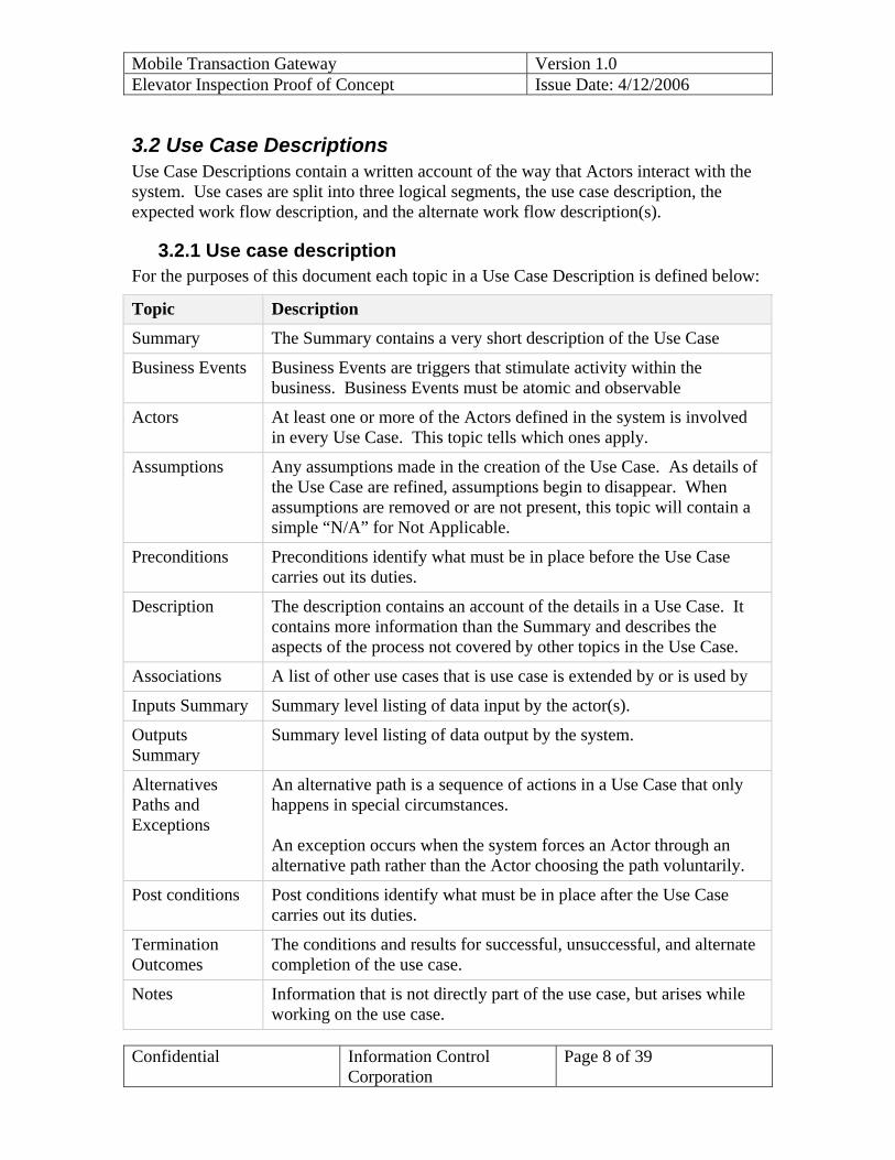
3.2 Use Case Descriptions Use Case Descriptions contain a written account of the way that Actors interact with the system. Use cases are split into three logical segments, the use case description, the expected work flow description, and the alternate work flow description(s).
3.2.1 Use case description For the purposes of this document each topic in a Use Case Description is defined below:
Topic Description
Summary The Summary contains a very short description of the Use Case
Business Events Business Events are triggers that stimulate activity within the business. Business Events must be atomic and observable
Actors At least one or more of the Actors defined in the system is involved in every Use Case. This topic tells which ones apply.
Assumptions Any assumptions made in the creation of the Use Case. As details of the Use Case are refined, assumptions begin to disappear. When assumptions are removed or are not present, this topic will contain a simple “N/A” for Not Applicable.
Preconditions Preconditions identify what must be in place before the Use Case carries out its duties.
Description The description contains an account of the details in a Use Case. It contains more information than the Summary and describes the aspects of the process not covered by other topics in the Use Case.
Associations A list of other use cases that is use case is extended by or is used by
Inputs Summary Summary level listing of data input by the actor(s).
Outputs Summary
Summary level listing of data output by the system.
Alternatives Paths and Exceptions
An alternative path is a sequence of actions in a Use Case that only happens in special circumstances. An exception occurs when the system forces an Actor through an alternative path rather than the Actor choosing the path voluntarily.
Post conditions Post conditions identify what must be in place after the Use Case carries out its duties.
Termination Outcomes
The conditions and results for successful, unsuccessful, and alternate completion of the use case.
Notes Information that is not directly part of the use case, but arises while working on the use case.

Mobile Transaction Gateway Version 1.0 Elevator Inspection Proof of Concept Issue Date: 4/12/2006
Confidential Information Control Corporation
Page 9 of 39
3.2.2 Events This section describes the events that occur as part of the fulfillment of the use case detailed in the Use Case Description. The following format is used to describe both the flow of events and any alternate flow(s) that may exist.
Flow Name
Description
The “Flow Name” column is used to group the flow or portions of the flow being described. In the case where a use case has several segmented flows that make up the main work flow, each segment would be named in this column for clarity. The “Description” column contains a description of what will happen at the prescribed point in the workflow

Mobile Transaction Gateway Version 1.0 Elevator Inspection Proof of Concept Issue Date: 4/12/2006
Confidential Information Control Corporation
Page 10 of 39
3.3 Use Case Association Diagram
Figure 2

Mobile Transaction Gateway Version 1.0 Elevator Inspection Proof of Concept Issue Date: 4/12/2006
Confidential Information Control Corporation
Page 11 of 39
3.4 Use Cases
3.4.1 Use Case Authenticate User Summary Every user that wishes to access the Elevator Inspection Proof of
Concept application must first be authenticated
Business Event(s)
Actor(s) Smart Client, Transaction Gateway
Assumptions
Preconditions Credentials for verification have been submitted to the system through an approved channel
Description The system authenticates the user submitted in one of two ways, either directly online, or through the use of cached data (in a disconnected smart client).
Associations Login to Web Application, Login in to Smart Client Application
Inputs Summary
Field Data Type Length *LoginId string 100 *Password string 12 UserId Int 4
Outputs Summary
Security Token
Alternative Paths and Exceptions
Invalid Password or User ID Unable to Authenticate User (data unavailable)
Post-conditions A security Token is returned to the calling routine
Termination Outcomes
Unable to Authenticate User
Notes There are no limits currently set on login attempts and no authentication timeout has been defined. All data will be encrypted for transfer.
3.4.1.1 Flow of Events Flow Name
Description
Authentication
An authentication request is received

Mobile Transaction Gateway Version 1.0 Elevator Inspection Proof of Concept Issue Date: 4/12/2006
Confidential Information Control Corporation
Page 12 of 39
request The system checks the user credentials Authentication successful
Credentials are valid
A security token, containing authorization information is generated The security token is returned to the calling routine
3.4.1.2 Alternate Flow of Events: Invalid Password or UserID Flow Name
Description
Authentication fails
The authentication request fails either due to an invalid UserID or invalid Password
System logs the failed login attempt System returns a login error to the calling routine
3.4.1.3 Alternate Flow of Events: Unable to Authenticate User Flow Name
Description
Authentication fails
The authentication request fails because the login authority is unavailable
The system logs the failed call to the login authority The system returns a login error to the calling routine

Mobile Transaction Gateway Version 1.0 Elevator Inspection Proof of Concept Issue Date: 4/12/2006
Confidential Information Control Corporation
Page 13 of 39
3.4.2 Use Case Login to Web Application Summary A user provides credentials to log into the web application
Business Event(s)
Actor(s) Supervisor Dispatcher Support Staff
Assumptions The user has access to a workstation with a working internet browser
Preconditions The user has a valid login and password.
Description A user must first log into the system before any of the functionality may be accessed. To log into the web application a user provides a login id (a valid email address) and password
Associations Authenticate User
Inputs Summary
Field Data Type Length *LoginId string 100 *Password string 12
Outputs Summary
Success code Security Token
Alternative Paths and Exceptions
Invalid UserID or Password Unable to Authenticate User
Post-conditions User is authenticated against the system and “moved” to their default workspace
Termination Outcomes
Invalid UserID or Password/Unable to Authenticate User – The user is returned to the login page
Notes
3.4.2.1 Flow of Events Flow Name
Description
Login User navigates to application entry point User is prompted to enter login credentials User enters credentials Credentials are submitted to the system for approval Application receives success code and security token Application displays user’s default workspace

Mobile Transaction Gateway Version 1.0 Elevator Inspection Proof of Concept Issue Date: 4/12/2006
Confidential Information Control Corporation
Page 14 of 39
3.4.2.2 Alternate Flow of Events: Flow Name
Description
Authentication failed
Failure displayed to user
Returned to Login Screen
Mobile Transaction Gateway Version 1.0 Elevator Inspection Proof of Concept Issue Date: 4/12/2006
Confidential Information Control Corporation
Page 15 of 39
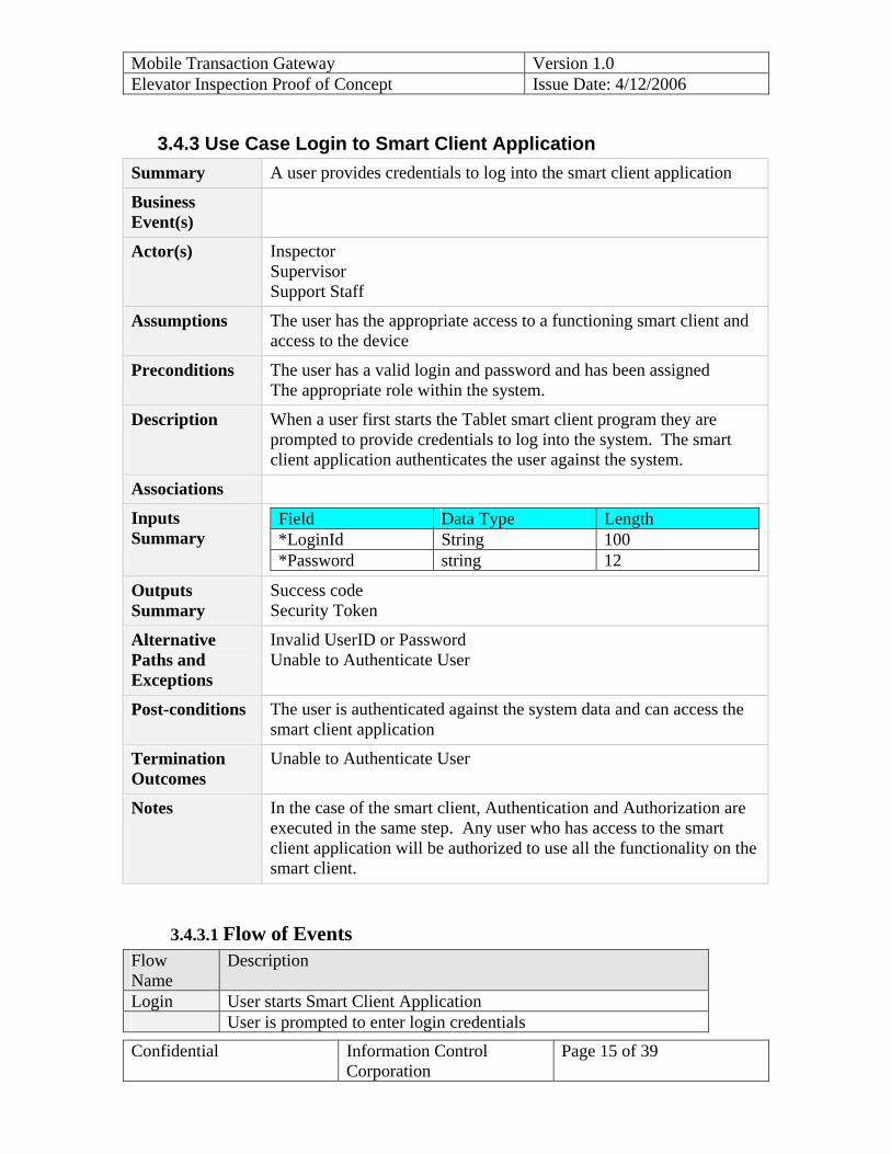
3.4.3 Use Case Login to Smart Client Application Summary A user provides credentials to log into the smart client application
Business Event(s)
Actor(s) Inspector Supervisor Support Staff
Assumptions The user has the appropriate access to a functioning smart client and access to the device
Preconditions The user has a valid login and password and has been assigned The appropriate role within the system.
Description When a user first starts the Tablet smart client program they are prompted to provide credentials to log into the system. The smart client application authenticates the user against the system.
Associations
Inputs Summary
Field Data Type Length *LoginId String 100 *Password string 12
Outputs Summary
Success code Security Token
Alternative Paths and Exceptions
Invalid UserID or Password Unable to Authenticate User
Post-conditions The user is authenticated against the system data and can access the smart client application
Termination Outcomes
Unable to Authenticate User
Notes In the case of the smart client, Authentication and Authorization are executed in the same step. Any user who has access to the smart client application will be authorized to use all the functionality on the smart client.
3.4.3.1 Flow of Events Flow Name
Description
Login User starts Smart Client Application User is prompted to enter login credentials

Mobile Transaction Gateway Version 1.0 Elevator Inspection Proof of Concept Issue Date: 4/12/2006
Confidential Information Control Corporation
Page 16 of 39
User enters credentials Credentials are submitted to Smart Client data cache for approval Smart Client approves user Smart Client displays users cached tasks in process
3.4.3.2 Alternate Flow of Events: Flow Name
Description
Authentication failed
User is denied access to Smart Client functionality
Returned to login screen

Mobile Transaction Gateway Version 1.0 Elevator Inspection Proof of Concept Issue Date: 4/12/2006
Confidential Information Control Corporation
Page 17 of 39
3.4.4 Use Case Logout Smart Client Application Summary User logs out of the system. The user may logout at any time
Business Event(s)
Actor(s) Inspector Supervisor
Assumptions The user is logged into the system.
Preconditions
Description The user may elect to logout at any point in the user session and the state will be transmitted to the server. The application will ask the user to save any unsaved work
Associations
Inputs Summary
Outputs Summary
Alternative Paths and Exceptions
Post-conditions The user is logged out of the system and unable to do any work until logged back in.
Termination Outcomes
Notes
3.4.4.1 Flow of Events Flow Name
Description
Logout User chooses the Logout button to initiate. Application prompts use to save unsaved work Application submits completed job tickets to message processing
subsystem
3.4.4.2 Alternate Flow of Events: Connectivity Unavailable Flow Name
Description
User signs out but server is unreachable

Mobile Transaction Gateway Version 1.0 Elevator Inspection Proof of Concept Issue Date: 4/12/2006
Confidential Information Control Corporation
Page 18 of 39
Work is queued by message delivery subsystem until connectivity returns

Mobile Transaction Gateway Version 1.0 Elevator Inspection Proof of Concept Issue Date: 4/12/2006
Confidential Information Control Corporation
Page 19 of 39
3.4.5 Use Case Logout Web Summary User logs out of the system or is automatically logged out after a
period of inactivity. The user may log out at any time
Business Event(s)
Actor(s) Supervisor Dispatcher Support Staff
Assumptions The user is logged into the system.
Preconditions
Description The system will log users out after a certain period of inactivity or the user may elect to logout at any point.
Associations
Inputs Summary
Outputs Summary
Alternative Paths and Exceptions
Post-conditions The user is logged out of the system and unable to do any work until logged back in.
Termination Outcomes
Notes
3.4.5.1 Flow of Events Flow Name
Description
Logout User clicks logout button to initiate user logout. System notes period of inactivity and initiates user logout. System saves the state of the user. User is logged out.
3.4.5.2 Alternate Flow of Events: Flow Name
Description

Mobile Transaction Gateway Version 1.0 Elevator Inspection Proof of Concept Issue Date: 4/12/2006
Confidential Information Control Corporation
Page 20 of 39
3.4.6 Use Case Modify Job Ticket Summary The inspector is able to complete a job ticket on the Smart Client
Business Event(s)
Actor(s) Inspector
Assumptions A user is logged into the system.
Preconditions
Description The user is presented with a list of available job tickets, ordered by scheduled start time. The user may select any job ticket; edit any allowed fields on the job ticket. They may choose to mark a job as complete. It will then be transferred via the transaction gateway via the Smart Client Route Message use case.
Associations Smart Client Route Message, Smart Client Receive Job Tickets
Inputs Summary
Job Ticket
Outputs Summary
Job Ticket
Alternative Paths and Exceptions
Edit Canceled Save Failed
Post-conditions Changes to the job ticket are saved by the system
Termination Outcomes
Notes
3.4.6.1 Flow of Events Flow Name
Description
Complete Job Ticket
Application generates Job Ticket list
User selects Job Ticket from list User edits Job Ticket The user saves the Job Ticket If marked completed, The Job Ticket is queued for transfer by the
system.

Mobile Transaction Gateway Version 1.0 Elevator Inspection Proof of Concept Issue Date: 4/12/2006
Confidential Information Control Corporation
Page 21 of 39
3.4.6.2 Alternate Flow of Events: Server Unavailable Flow Name
Description
Edit Canceled
User is returned to main screen, all edits from last save are lost
Save Failed
The application notifies user that the save has failed, and displays any error messages.

Mobile Transaction Gateway Version 1.0 Elevator Inspection Proof of Concept Issue Date: 4/12/2006
Confidential Information Control Corporation
Page 22 of 39
3.4.7 Use Case Smart Client Send Job Ticket Summary Smart Client will send job tickets to the Transaction Gateway system
to update Job Ticket data.
Business Event(s)
Actor(s) Smart Client System Transaction Gateway System
Assumptions Smart Client is powered and can connect to Transaction Gateway system
Preconditions Smart Client has queued job tickets for routing and they are ready to be processed. User must be logged into the system, and the application must be running
Description The Transaction Gateway system will accept Job Tickets from the Smart Client, then route and process the them accordingly, returning a result job ticket
Associations
Inputs Summary
Job Ticket
Outputs Summary
Job Ticket
Alternative Paths and Exceptions
System disconnects Job ticket cannot be processed by Transaction Gateway system
Post-conditions
Termination Outcomes
System disconnects
Notes
3.4.7.1 Flow of Events Flow Name
Description
Connect Smart Client waits for connection to be established Smart Client will notify Smart Client of connectivity change Smart Client reads send queue Process Smart Client sends job ticket Transaction Gateway system receives job ticket Transaction Gateway routes job ticket to file system
Mobile Transaction Gateway Version 1.0 Elevator Inspection Proof of Concept Issue Date: 4/12/2006
Confidential Information Control Corporation
Page 23 of 39
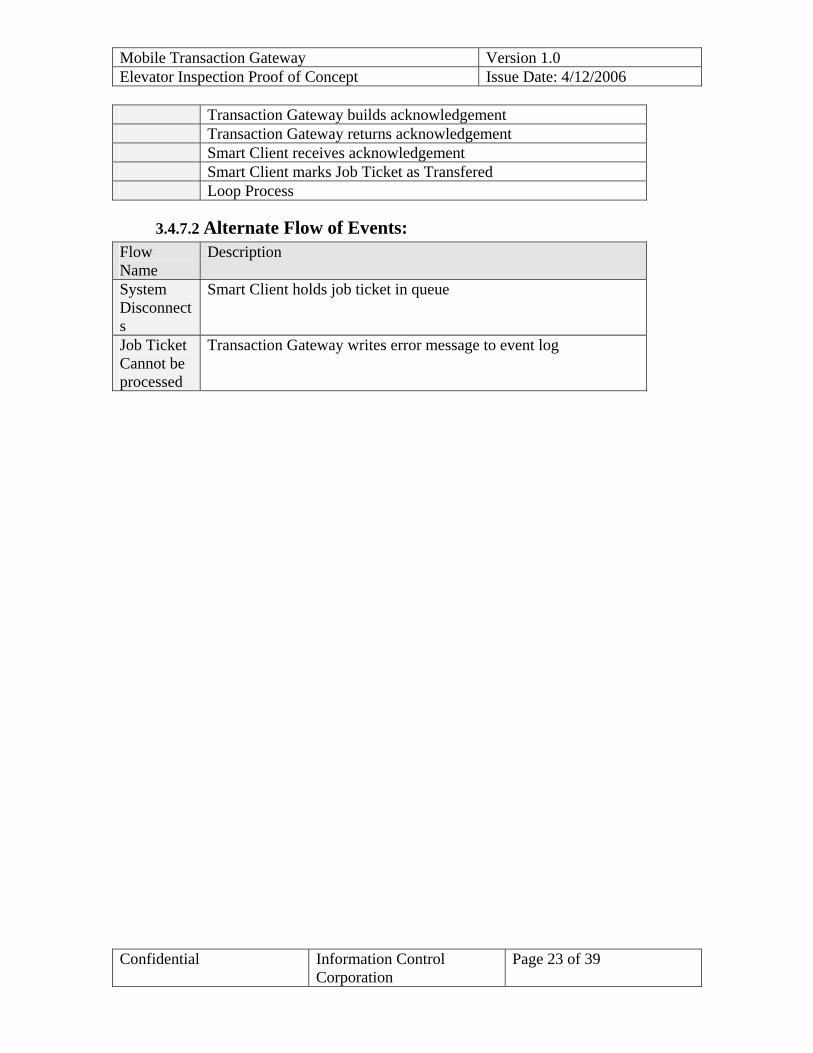
Transaction Gateway builds acknowledgement Transaction Gateway returns acknowledgement Smart Client receives acknowledgement Smart Client marks Job Ticket as Transfered Loop Process
3.4.7.2 Alternate Flow of Events: Flow Name
Description
System Disconnects
Smart Client holds job ticket in queue
Job Ticket Cannot be processed
Transaction Gateway writes error message to event log
Mobile Transaction Gateway Version 1.0 Elevator Inspection Proof of Concept Issue Date: 4/12/2006
Confidential Information Control Corporation
Page 24 of 39
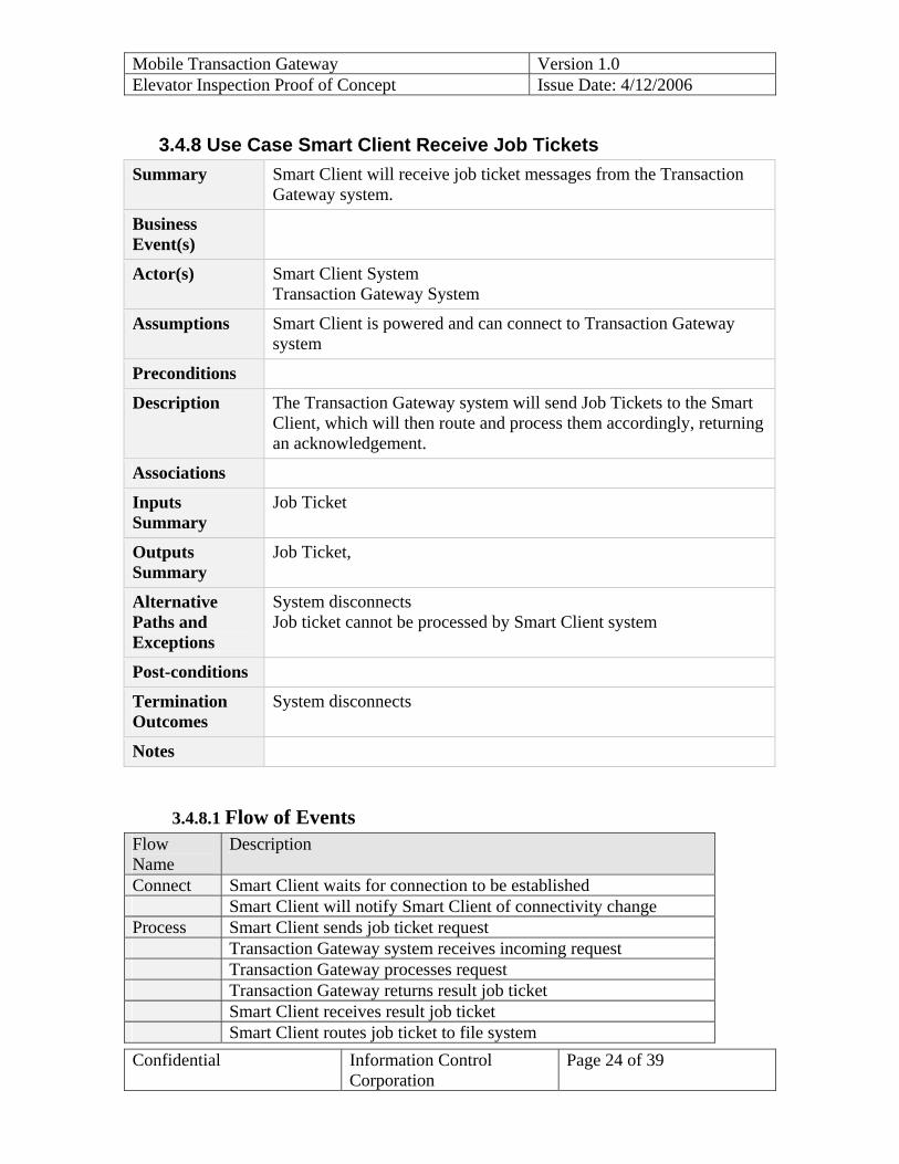
3.4.8 Use Case Smart Client Receive Job Tickets Summary Smart Client will receive job ticket messages from the Transaction
Gateway system.
Business Event(s)
Actor(s) Smart Client System Transaction Gateway System
Assumptions Smart Client is powered and can connect to Transaction Gateway system
Preconditions
Description The Transaction Gateway system will send Job Tickets to the Smart Client, which will then route and process them accordingly, returning an acknowledgement.
Associations
Inputs Summary
Job Ticket
Outputs Summary
Job Ticket,
Alternative Paths and Exceptions
System disconnects Job ticket cannot be processed by Smart Client system
Post-conditions
Termination Outcomes
System disconnects
Notes
3.4.8.1 Flow of Events Flow Name
Description
Connect Smart Client waits for connection to be established Smart Client will notify Smart Client of connectivity change Process Smart Client sends job ticket request Transaction Gateway system receives incoming request Transaction Gateway processes request Transaction Gateway returns result job ticket Smart Client receives result job ticket Smart Client routes job ticket to file system

Mobile Transaction Gateway Version 1.0 Elevator Inspection Proof of Concept Issue Date: 4/12/2006
Confidential Information Control Corporation
Page 25 of 39
Smart Client builds acknowledgement Smart Client returns acknowledgement Transaction Gateway receives acknowledgement Transaction Gateway marks Job Ticket as transferred Loop Process
3.4.8.2 Alternate Flow of Events: Flow Name
Description
System Disconnects
Smart Client holds request in queue
Job Ticket Cannot be processed
Smart Client Writes error to event log

Mobile Transaction Gateway Version 1.0 Elevator Inspection Proof of Concept Issue Date: 4/12/2006
Confidential Information Control Corporation
Page 26 of 39
3.4.9 Use Case Process Job Ticket Update Summary Smart Client job tickets are sent to Transaction Gateway system for
updating
Business Event(s)
Actor(s) Transaction Gateway System
Assumptions Smart Client has online connectivity
Preconditions
Description The Transaction Gateway system accepts job tickets and processes the data contained therein. Any concurrency conflicts are stored and the event log is updated.
Associations Route Message
Inputs Summary
Update Data
Outputs Summary
Conflict Record
Alternative Paths and Exceptions
Connectivity Loss
Post-conditions
Termination Outcomes
System disconnects
Notes
3.4.9.1 Flow of Events Flow Name
Description
Initiate Inspector initiates update data Process Smart Client sends update Smart Client initiates Route Message Transaction Gateway system deserializes request Transaction Gateway queries current data Transaction Gateway compares current data to request starting
data Transaction Gateway generates conflict record if data changes on
server Transaction Gateway updates and saves data if no changes on

Mobile Transaction Gateway Version 1.0 Elevator Inspection Proof of Concept Issue Date: 4/12/2006
Confidential Information Control Corporation
Page 27 of 39
server Inspector updates data, if wanted and resends LOOP Inspector ends if updates not wanted
3.4.9.2 Alternate Flow of Events: Flow Name
Description
System Disconnects
Smart Client holds job ticket in queue
Queue Fails
Smart Client holds job ticket in queue

Mobile Transaction Gateway Version 1.0 Elevator Inspection Proof of Concept Issue Date: 4/12/2006
Confidential Information Control Corporation
Page 28 of 39
3.4.10 Use Case Reconcile Data in Conflict Summary The offline functionality offered by the smart client may result data
conflicts between the server and the local (smart client) data sets.
Business Event(s)
Actor(s)
Assumptions
Preconditions
Description If a remote user collects data and there is no connectivity to the server that data is stored locally until connectivity is restored. If the data that the remote user is updating is updated by another user before the remote user regains connectivity, there will be a conflict. When data is found to be in conflict, the system will create an event in the system event log
Associations
Inputs Summary
Server Record Local Record
Outputs Summary
Reconciled Record
Alternative Paths and Exceptions
Post-conditions The data in the system has been accepted as accurate and either left as is or updated
Termination Outcomes
Notes
3.4.10.1 Flow of Events Flow Name
Description
System checks Job Ticket number If Ticket has already been received, message is sent to event log
3.4.10.2 Alternate Flow of Events: Flow Name
Description

Mobile Transaction Gateway Version 1.0 Elevator Inspection Proof of Concept Issue Date: 4/12/2006
Confidential Information Control Corporation
Page 29 of 39

Mobile Transaction Gateway Version 1.0 Elevator Inspection Proof of Concept Issue Date: 4/12/2006
Confidential Information Control Corporation
Page 30 of 39
3.4.11 Use Case View Job Ticket List on Smart Client Summary Job Tickets are presented in list form, ordered by scheduled start time
Business Event(s)
Actor(s) Inspector
Assumptions
Preconditions
Description The list is generated from all Job Tickets on the system. Summary data is displayed, in list form, ordered by scheduled start time. The user may select a job ticket to modify it. A button to synchronize data with the Transaction gateway is also displayed.
Associations View Job Ticket
Inputs Summary
Job Tickets
Outputs Summary
Job Ticket.
Alternative Paths and Exceptions
Synchronize button pressed
Post-conditions The Job Ticket List is displayed
Termination Outcomes
Notes
3.4.11.1 Flow of Events Flow Name
Description
System Display Job Ticket summary information in list form, ordered by agent, scheduled start time
3.4.11.2 Alternate Flow of Events: Flow Name
Description
Synchronize button pressed
Smart Client send any Completed Job Tickets to Transaction Gateway
Transaction Gateway sends any new Job Tickets to Smart Client

Mobile Transaction Gateway Version 1.0 Elevator Inspection Proof of Concept Issue Date: 4/12/2006
Confidential Information Control Corporation
Page 31 of 39
3.4.12 Use Case View Job Ticket List via Web Summary Job Tickets are presented in list form, ordered by inspector and
scheduled start time
Business Event(s)
Actor(s) Supervisor Support Staff Dispatcher
Assumptions
Preconditions
Description The list is generated from all Job Tickets on the system. Summary data is displayed, in list form, ordered by inspector and scheduled start time. The user may select a job ticket to display it.
Associations View Job Ticket
Inputs Summary
Job Tickets
Outputs Summary
Job Ticket.
Alternative Paths and Exceptions
Post-conditions The Job Ticket List is displayed
Termination Outcomes
Notes
3.4.12.1 Flow of Events Flow Name
Description
System Display Job Ticket summary information in list form, ordered by agent, scheduled start time
3.4.12.2 Alternate Flow of Events: Flow Name
Description

Mobile Transaction Gateway Version 1.0 Elevator Inspection Proof of Concept Issue Date: 4/12/2006
Confidential Information Control Corporation
Page 32 of 39
3.4.13 Use Case View Job Ticket via Web Summary A Job Ticket is displayed
Business Event(s)
Actor(s) Supervisor Dispatcher Support Staff
Assumptions
Preconditions
Description All Job Ticket data is displayed via a web page. The job ticket is selected via use case View Job Ticket List via Web
Associations View Job Ticket List
Inputs Summary
Job Ticket
Outputs Summary
Alternative Paths and Exceptions
Post-conditions
Termination Outcomes
Notes
3.4.13.1 Flow of Events Flow Name
Description
System checks Job Ticket number System displays Job Ticket via web page
3.4.13.2 Alternate Flow of Events: Flow Name
Description

Mobile Transaction Gateway Version 1.0 Elevator Inspection Proof of Concept Issue Date: 4/12/2006
Confidential Information Control Corporation
Page 33 of 39
4. High Level Application Architecture The application is designed as a smart client application. It communicates wirelessly via encrypted web services. Job tickets are pushed and pulled via the Smart Client. The Transaction Gateway tracks job tickets sent and received, and displays job tickets on a web page.
Internal Firewall
Supervisors
SFTP XML Filed
Transfer
Data Layer
Transaction GatewayData Store
Network Access Layer
Internet Access
Inspectors
Legacy Systems
ClickFocus
Application Server
Dispatchers Cell Tower
Verizon
Figure 3

Mobile Transaction Gateway Version 1.0 Elevator Inspection Proof of Concept Issue Date: 4/12/2006
Confidential Information Control Corporation
Page 34 of 39
5. User Interfaces This section offers mock-ups of application screens. The mock-ups are not final screen designs, but are to help visualize the data being displayed. Login and Logout screens mock-ups are not included, as they change little from application to application.
5.1.1 Web Screens These screens are displayed by the Transaction Gateway. They allow users to review job tickets that pending transfer and those that have been returned from the smart client.
5.1.1.1 Job Ticket List Screen
This screen displays a list of job tickets, ordered by inspector, start date, and start time. Clicking on a line will display the Job Ticket.

Mobile Transaction Gateway Version 1.0 Elevator Inspection Proof of Concept Issue Date: 4/12/2006
Confidential Information Control Corporation
Page 35 of 39
5.1.1.2 Web Job Ticket Screen State of Ohio, Department of Commerce, DIC, Bob Taft Governor, Lt. Governor Jennette Bradley , Director
INSPECTION JOB TICKET #: EL-04-R-101262Inspection Description:
Inspection Name: DIN:
Scheduled Start Time:Scheduled Ending Time:
State Object ID#:PROJECT/OBJECT:Name:
Address:
City, Zip:
County:
Location:
Owner ID#: 7203MUSKINGUM COUNTY CONVENTIONCENTER205 N 5TH STZANESVILLE, OH 43701
Plan Requirements:
From Dispatch:
Date:
___ ___ : ___ ___Contact Name:Contact Phone:Caller Name:
Object-or-Site Specific Data:
Installer Object-or-Maintenance Co. Local ID2
Elevator Status
Elev Type Pwr Type Capacity2000
Landings Manufacturer Speed25
Travel Load Class - Frt
Inspection Standards Plan Rev. -Dt Recovd Elevator Use Last Sfty Tst Last Load Tst Sealed Off
Permanent Record Message:
Last Inspection Results: Date: 11/13/2003 Inspector: Inspection Type:
Violation codes:
Corrected?
FINDINGS:COMPLETED: Choose A or B:
THE INSPECTIONPASSED
FAILED - Required Comments
Violation Codes / Comments:
START TIME
CANCELED CODE
A.
B.
Check List Completed: Review with Customer
Inspector Name
Checked By:Customer NameFindings Review With:
Fail
Pass
AV6, T-1, R-1, R-4
Y N
UNKNOWN
Y N
AO / VarianceMessages
Figure 4
Each Job Ticket is displayed read only. All data contained on the ticket is displayed, including any information entered by the inspector on the smart client.

Mobile Transaction Gateway Version 1.0 Elevator Inspection Proof of Concept Issue Date: 4/12/2006
Confidential Information Control Corporation
Page 36 of 39
5.1.2 Smart Client Screens
5.1.2.1 Welcome (Main Workspace) The main workspace is where the user is directed after login, most application functions are initiated from this screen.
Form TitleForm Title
ID: INOIRRP2 Ohio Elevator Records Management System Page: 1
Sequ: Inspector, Inspection DateStart TimeSupervisor:
Inspector’s Daily dispatched Inspection Report
Inspection Date: 05/02/2004 DIN: EL3117 Name: FERGUSON, J.
Job Ticket #, Inspection TypeState Discipline Elevator Type Contact Name, CountyStart, End Time Power Type Contact Phone Address Comments
El-04-RSI-098389 ANNR UNIZAN UNIZAN MUSKINGUM28385 EL P BUTCH MILLS 422 MAIN ST 07:00 am, 06:00 PM E 740-588-6815 ZANSVILLE, OH 43701
El-04-RSI-101263 SEMI BUSINESS EQUIPMENT CO BUSINESS EQUIPMENT CO MUSKINGUM28385 EL P BUTCH MILLS 422 MAIN ST 07:00 am, 06:00 PM E 740-588-6815 ZANSVILLE, OH 43701
El-04-RSI-101264 ANN FIORIWARE INC. FIORIWARE INC MUSKINGUM31403 EL F 26 N 3RF ST 07:00 am, 06:00 PM E 740-454-3399 ZANSVILLE, OH 43701
Inspection Count: 3
Connection Status: ONLINE
Select
Select
Select
Synchronize Logout
Figure 5
All uncompleted job tickets are displayed, in order of start time. Clicking on the select button will display the Job Ticket Screen. The Synchronize button causes the application to check for pending tickets and transfer any completed tickets. The logout button returns the application to the login screen.

Mobile Transaction Gateway Version 1.0 Elevator Inspection Proof of Concept Issue Date: 4/12/2006
Confidential Information Control Corporation
Page 37 of 39
5.1.2.2 Job Ticket Screen Job TicketJob Ticket
State of Ohio, Department of Commerce, DIC, Bob Taft Governor, Lt. Governor Jennette Bradley , Director
INSPECTION JOB TICKET #: EL-04-R-101262Inspection Description:
Inspection Name: DIN:
Scheduled Start Time:Scheduled Ending Time:
State Object ID#:PROJECT/OBJECT:Name:
Address:
City, Zip:
County:
Location:
Owner ID#: 7203MUSKINGUM COUNTY CONVENTIONCENTER205 N 5TH STZANESVILLE, OH 43701
Plan Requirements:
From Dispatch:
Date:
___ ___ : ___ ___Contact Name:Contact Phone:Caller Name:
Object-or-Site Specific Data:
Installer Object-or-Maintenance Co. Local ID2
Elevator Status
Elev Type Pwr Type Capacity2000
Landings Manufacturer Speed25
Travel Load Class - Frt
Inspection Standards Plan Rev. -Dt Recovd Elevator Use Last Sfty Tst Last Load Tst Sealed Off
Permanent Record Message:
Last Inspection Results: Date: 11/13/2003 Inspector: Inspection Type:
Violation codes:
Corrected?
FINDINGS:COMPLETED: Choose A or B:
THE INSPECTIONPASSED
FAILED - Required Comments
Violation Codes / Comments:
START TIME
CANCELED CODE
A.
B.
Check List Completed: Review with Customer
Inspector Name
Checked By:Customer NameFindings Review With:
Fail
Pass
AV6, T-1, R-1, R-4
Y N
UNKNOWN
Y N
CancelComplete
AO / VarianceMessages
Pause
New Violation
Save
Figure 6
The form allows the inspector to modify the same fields they do today. The Pause button saves any changes, and stops the job timer. Cancel returns to the previous screen. Complete saves the ticket, and marks it for transfer. Save saves the current Job Ticket.

Mobile Transaction Gateway Version 1.0 Elevator Inspection Proof of Concept Issue Date: 4/12/2006
Confidential Information Control Corporation
Page 38 of 39
6. Environment 6.1.1 Hardware:
6.1.1.1 Servers Intel CPU 1 GHZ or greater 256 MB Memory or greater 2 GB free disk space
6.1.2 Server Software: SQL Server 2000 Windows Server 2000 or 2003 .NET Framework 1.1 ASP.NET
6.1.3 Development Software Browser: IE 5.0 or later Visual Studio 2003
6.1.4 Client Browser: IE 5.0 or later Windows XP Tablet Edition Tablet PC with 5 GB of free disk space and 256 MB or greater of memory
6.1.5 Special Verizon Wireless network cards

Mobile Transaction Gateway Version 1.0 Elevator Inspection Proof of Concept Issue Date: 4/12/2006
Confidential Information Control Corporation
Page 39 of 39
Appendix A: Sign-off The signature of this document provides the approval of the Elevator Inspection Proof of Concept project to the overall functionality and design of the application represented in this document. This also provides the approval to proceed forward with the design into the development phase: W. Thomas Hart_______________ Date: _____________ Chief Information Officer, Ohio Department of Commerce Bruce Reed _______________ Date: _____________ Project Manager, Managed Solutions Group - Information Control Corporation