Model 70200 Universal Oil Primary Control - ALBRO · PDF fileModel 70200 Universal Oil Primary...
4
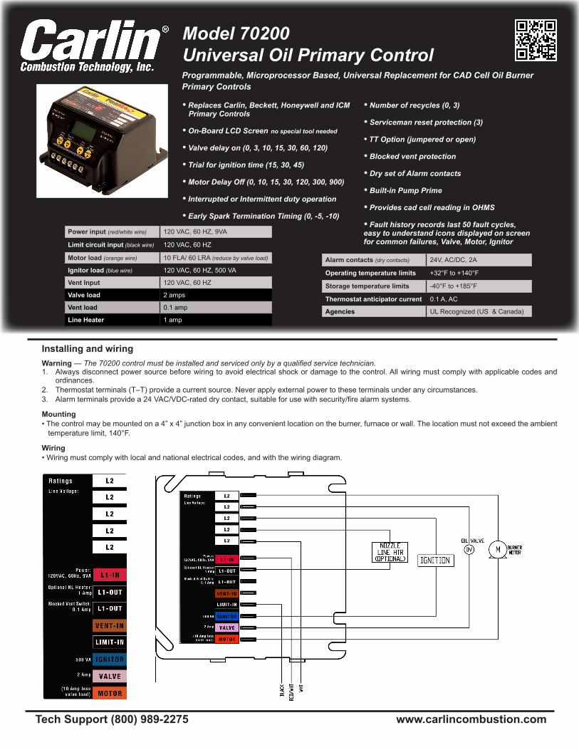
Model 70200 Universal Oil Primary Control Tech Support (800) 989-2275 www.carlincombustion.com Installing and wiring Warning — The 70200 control must be installed and serviced only by a qualified service technician. 1. Always disconnect power source before wiring to avoid electrical shock or damage to the control. All wiring must comply with applicable codes and ordinances. 2. Thermostat terminals (T–T) provide a current source. Never apply external power to these terminals under any circumstances. 3. Alarm terminals provide a 24 VAC/VDC-rated dry contact, suitable for use with security/fire alarm systems. Mounting • The control may be mounted on a 4” x 4” junction box in any convenient location on the burner, furnace or wall. The location must not exceed the ambient temperature limit, 140°F. Wiring • Wiring must comply with local and national electrical codes, and with the wiring diagram. Power input (red/white wire) 120 VAC, 60 HZ, 9VA Limit circuit input (black wire)) 120 VAC, 60 HZ Motor load (orange wire) 10 FLA/ 60 LRA (reduce by valve load) Ignitor load (blue wire)) 120 VAC, 60 HZ, 500 VA Vent Input 120 VAC, 60 HZ Valve load 2 amps Vent load 0.1 amp Line Heater 1 amp Alarm contacts (dry contacts) 24V, AC/DC, 2A Operating temperature limits +32°F to +140°F Storage temperature limits -40°F to +185°F Thermostat anticipator current 0.1 A, AC Agencies UL Recognized (US & Canada) • Replaces Carlin, Beckett, Honeywell and ICM Primary Controls • On-Board LCD Screen no special tool needed • Valve delay on (0, 3, 10, 15, 30, 60, 120) • Trial for ignition time (15, 30, 45) • Motor Delay Off (0, 10, 15, 30, 120, 300, 900) • Interrupted or Intermittent duty operation • Early Spark Termination Timing (0, -5, -10) • Number of recycles (0, 3) • Serviceman reset protection (3) • TT Option (jumpered or open) • Blocked vent protection • Dry set of Alarm contacts • Built-in Pump Prime • Provides cad cell reading in OHMS • Fault history records last 50 fault cycles, easy to understand icons displayed on screen for common failures, Valve, Motor, Ignitor Programmable, Microprocessor Based, Universal Replacement for CAD Cell Oil Burner Primary Controls
Transcript of Model 70200 Universal Oil Primary Control - ALBRO · PDF fileModel 70200 Universal Oil Primary...
Model 70200 Universal Oil Primary Control
Tech Support (800) 989-2275 www.carlincombustion.com
Installing and wiringWarning — The 70200 control must be installed and serviced only by a qualified service technician.1. Always disconnect power source before wiring to avoid electrical shock or damage to the control. All wiring must comply with applicable codes and
ordinances.2. Thermostat terminals (T–T) provide a current source. Never apply external power to these terminals under any circumstances.3. Alarm terminals provide a 24 VAC/VDC-rated dry contact, suitable for use with security/fire alarm systems.
Mounting• The control may be mounted on a 4” x 4” junction box in any convenient location on the burner, furnace or wall. The location must not exceed the ambient temperature limit, 140°F.
Wiring• Wiring must comply with local and national electrical codes, and with the wiring diagram.
Power input (red/white wire) 120 VAC, 60 HZ, 9VA
Limit circuit input (black wire)) 120 VAC, 60 HZ
Motor load (orange wire) 10 FLA/ 60 LRA (reduce by valve load)
Ignitor load (blue wire)) 120 VAC, 60 HZ, 500 VA
Vent Input 120 VAC, 60 HZ
Valve load 2 amps
Vent load 0.1 amp
Line Heater 1 amp
Alarm contacts (dry contacts) 24V, AC/DC, 2A
Operating temperature limits +32°F to +140°F
Storage temperature limits -40°F to +185°F
Thermostat anticipator current 0.1 A, AC
Agencies UL Recognized (US & Canada)
• Replaces Carlin, Beckett, Honeywell and ICM Primary Controls
• On-Board LCD Screen no special tool needed
• Valve delay on (0, 3, 10, 15, 30, 60, 120)
• Trial for ignition time (15, 30, 45) • Motor Delay Off (0, 10, 15, 30, 120, 300, 900)
• Interrupted or Intermittent duty operation
• Early Spark Termination Timing (0, -5, -10)
• Number of recycles (0, 3)
• Serviceman reset protection (3)
• TT Option (jumpered or open)
• Blocked vent protection
• Dry set of Alarm contacts
• Built-in Pump Prime
• Provides cad cell reading in OHMS
• Fault history records last 50 fault cycles, easy to understand icons displayed on screen for common failures, Valve, Motor, Ignitor
Programmable, Microprocessor Based, Universal Replacement for CAD Cell Oil Burner Primary Controls
© Copyright 2012 - Carlin Combustion Technology, Inc. Carlin part number MN70200S Rev. 08/28/2012
Do not start the burner if the combustion chamber contains oil or oil vapor.
Per UL requirements, the control will not turn on if the cad cell senses flame (light) during the self-test. If the cad cell sees flame, the control will remain in self-test mode until the cad cell no longer senses flame.
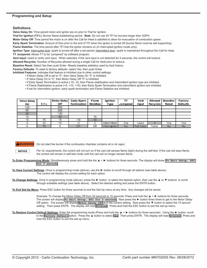
To Enter Programming Mode: Simultaneously press and hold the the ▲ + ► buttons for three seconds. The display will show: To Exit Setup, ESC for 3 seconds.
To View Current Settings: Once in programming mode (above), use the ► button to scroll through all options (see table above). The control will display the current setting for each option.
To Change Settings: Once in programming mode (above), press the ► button to select the desired option, then use the ▲ or ▼ buttons to scroll through available settings (see table above). Select the desired setting and press the ENTR button.
To Exit Set-Up Menu: Press ESC button for three seconds to exit the Set-Up menu at any time. Any changes will be saved.
Example: To change the Motor Delay Off from 30 seconds to 15 seconds: Press and hold the ▲ + ► buttons for three seconds. The screen will display To Exit Setup, ESC for 3 seconds. Now press the ► button three times to get to the Motor Delay Off option. The screen will display Motor Delay Off and the current setting. Now press the ▼ button to select the 15 second setting. Then press ENTR. The display will read Entered. Press and hold the ESC button to exit the set-up menu.
To Restore Control Default Settings: Enter the programming mode (Press and hold the ▲ + ► buttons for three seconds). Using the ► button, scroll to the Factory Default option. Press the ▲ button to select Yes. Then press ENTR. The display will read Entered. Press and hold the ESC button to exit the set-up menu.
Programming and Setup
Definitions:Valve Delay On: Time period motor and ignitor are on prior to Trial for Ignition.Trial for Ignition (T.F.I.): Burner flame-establishing period. Note: Do not use 45 TFI for burners larger than 3GPH.Motor Delay Off: Time period the motor is on after the Call for Heat is satisfied to allow for evacuation of combustion gases.Early Spark Termination: Amount of time prior to the end of TFI when the ignitor is turned off (burner flame must be self supporting).Flame Stabilize: The time period after TFI that the ignitor remains on (in interrupted ignition mode only).Ignition Type: Interrupted duty: spark is turned off after a set period; Intermittent duty: spark is maintained throughout the Call for Heat.TT Jumpered: Allows TT to be “jumpered” by software program.Vent Input: Used to verify vent input. When selected, if the vent input is not detected for 5 seconds, the control will lockout.Allowed Recycles: Number of Recycles allowed during a single Call for Heat prior to lockout.Baseline Reset: Select Yes then push Enter- Resets baseline statistics used by fault history.Factory Defaults: To reset to factory defaults- select Yes, then push Enter.Inhibited Features: indicates that feature is inhibited due to other control settings: • If Motor Delay Off is set to “0”, then Valve Delay On “0” is inhibited. • If Valve Delay On is “0”, then Motor Delay Off “0” is inhibited. • If Early Spark Termination is active (-10, -5), then Flame stabilization and Intermittent ignition type are inhibited. • If Flame Stabilization is active (+5, +10, +15), then Early Spark Termination and intermittent ignition are inhibited. • If set for intermittent ignition, early spark termination and Flame Stabilize are inhibited.
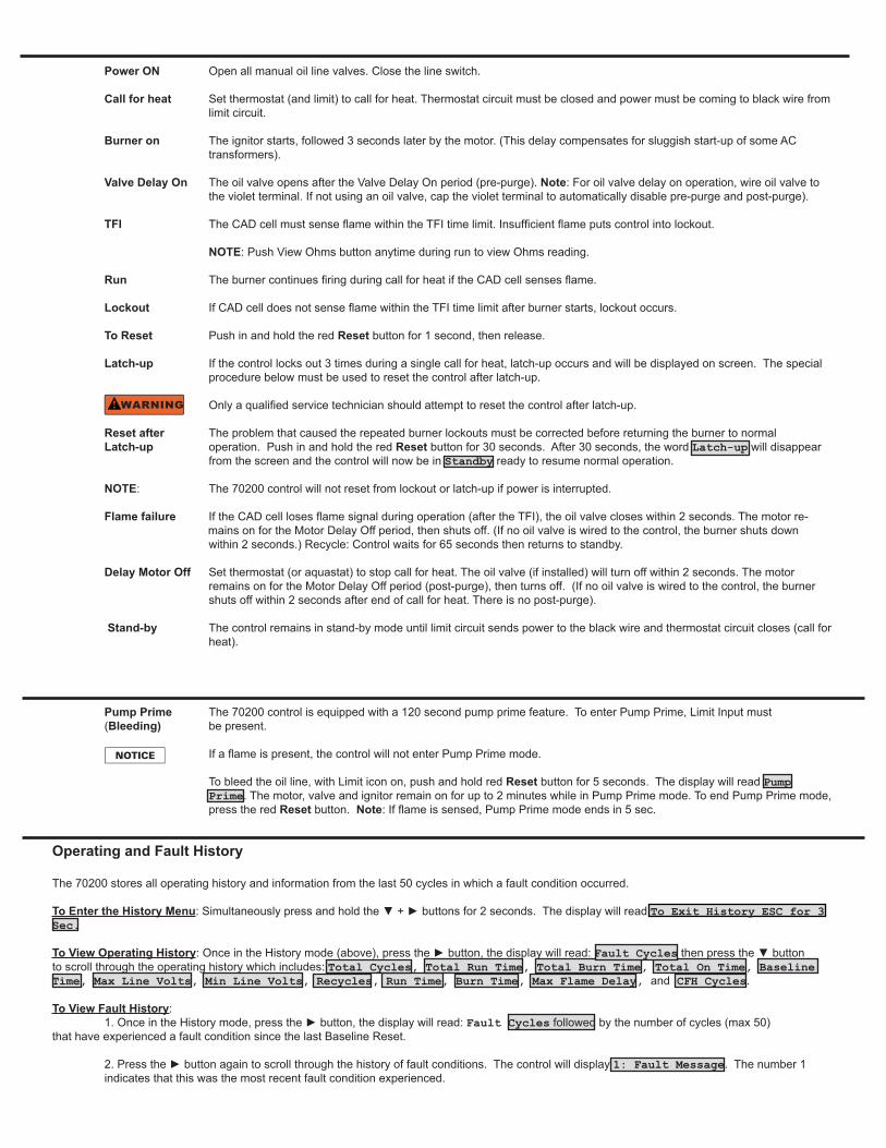
Power ON Open all manual oil line valves. Close the line switch. Call for heat Set thermostat (and limit) to call for heat. Thermostat circuit must be closed and power must be coming to black wire from limit circuit. Burner on The ignitor starts, followed 3 seconds later by the motor. (This delay compensates for sluggish start-up of some AC transformers).
Valve Delay On The oil valve opens after the Valve Delay On period (pre-purge). Note: For oil valve delay on operation, wire oil valve to the violet terminal. If not using an oil valve, cap the violet terminal to automatically disable pre-purge and post-purge).
TFI The CAD cell must sense flame within the TFI time limit. Insufficient flame puts control into lockout.
NOTE: Push View Ohms button anytime during run to view Ohms reading. Run The burner continues firing during call for heat if the CAD cell senses flame.
Lockout If CAD cell does not sense flame within the TFI time limit after burner starts, lockout occurs.
To Reset Push in and hold the red Reset button for 1 second, then release.
Latch-up If the control locks out 3 times during a single call for heat, latch-up occurs and will be displayed on screen. The special procedure below must be used to reset the control after latch-up. Only a qualified service technician should attempt to reset the control after latch-up. Reset after The problem that caused the repeated burner lockouts must be corrected before returning the burner to normal Latch-up operation. Push in and hold the red Reset button for 30 seconds. After 30 seconds, the word Latch-up will disappear from the screen and the control will now be in Standby ready to resume normal operation. NOTE: The 70200 control will not reset from lockout or latch-up if power is interrupted.
Flame failure If the CAD cell loses flame signal during operation (after the TFI), the oil valve closes within 2 seconds. The motor re- mains on for the Motor Delay Off period, then shuts off. (If no oil valve is wired to the control, the burner shuts down within 2 seconds.) Recycle: Control waits for 65 seconds then returns to standby. Delay Motor Off Set thermostat (or aquastat) to stop call for heat. The oil valve (if installed) will turn off within 2 seconds. The motor remains on for the Motor Delay Off period (post-purge), then turns off. (If no oil valve is wired to the control, the burner shuts off within 2 seconds after end of call for heat. There is no post-purge).
Stand-by The control remains in stand-by mode until limit circuit sends power to the black wire and thermostat circuit closes (call for heat).
Operating and Fault History
The 70200 stores all operating history and information from the last 50 cycles in which a fault condition occurred.
To Enter the History Menu: Simultaneously press and hold the ▼ + ► buttons for 2 seconds. The display will read To Exit History ESC for 3 Sec.
To View Operating History: Once in the History mode (above), press the ► button, the display will read: Fault Cycles then press the ▼ button to scroll through the operating history which includes: Total Cycles, Total Run Time, Total Burn Time, Total On Time, Baseline Time, Max Line Volts, Min Line Volts, Recycles, Run Time, Burn Time, Max Flame Delay, and CFH Cycles.
To View Fault History: 1. Once in the History mode, press the ► button, the display will read: Fault Cycles followed by the number of cycles (max 50) that have experienced a fault condition since the last Baseline Reset.
2. Press the ► button again to scroll through the history of fault conditions. The control will display 1: Fault Message. The number 1 indicates that this was the most recent fault condition experienced.
Pump Prime The 70200 control is equipped with a 120 second pump prime feature. To enter Pump Prime, Limit Input must (Bleeding) be present. If a flame is present, the control will not enter Pump Prime mode.
To bleed the oil line, with Limit icon on, push and hold red Reset button for 5 seconds. The display will read Pump Prime. The motor, valve and ignitor remain on for up to 2 minutes while in Pump Prime mode. To end Pump Prime mode, press the red Reset button. Note: If flame is sensed, Pump Prime mode ends in 5 sec.
Service & Troubleshooting
Burner (control) will not come onNo power to control
• Check line voltage to the control (at least 102 vac). • Check all electrical connections.
Control is in lockout • Press the reset button for 1 second.
CAD cell seeing light• Light is leaking into the burner housing, or
• CAD cell is defective, or
• there is a problem with the CAD cell wiring or holder.• If appliance was recently shut down, CAD cell may see residual
hot spots in chamber.To troubleshoot:• Press the ▲ button to display cad cell Ohms. Dark resis-
tance should be over 50K ohms, and room light resistance (control flipped open) should be less than 10K ohms. Replace cell if necessary, or reinstall and close the burner housing.
.• Press the ▲ button to display cad cell Ohms. Check for stray light by measuring the CAD cell resistance looking into the inactive combustion chamber. It should read greater than 50K ohms.
Other no start problemsIf the CAD cell is OK, • Valve lead voltage on too early. Correct bad connection. • Line voltage <90 VAC. Check line voltage. • Motor relay welded. If valve has no voltage, and line voltage
OK, the issue is a welded motor relay. Replace the control. • Motor current less than 0.2 Amps.
Repeated flame failures
Check for: • CAD cell is defective. Replace.• Air leaking into oil line causing flame out- check oil line
connections and filter gasket.• Defective nozzle causing flame to be erratic- change nozzle. • Excessive airflow or draft causing flame to leave burner head-
check for proper air band setting and draft.• Excessive back pressure causing flame to be erratic- check
appliance and flue for sooting/plugging.
Control locks out at end of TFI
Check for: • No oil to burner- check oil supply, filters, lines.• Shorted electrodes- inspect for cracked porcelain and replace
as needed.• Poor spark- check electrode spacing and condition per burner
manual. Replace or realign if necessary.• Nozzle clogged- replace nozzle.• Airflow too high- check air band setting.• Ignitor module defective- replace if no spark.• CAD cell defective.• Oil valve (if used) stuck in closed position.• Check wiring connections.
© Copyright 2012 - Carlin Combustion Technology, Inc. Carlin part number MN70200S Rev. 08/28/2012
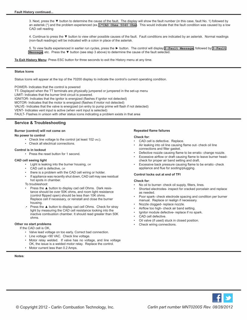
3. Next, press the ▼ button to determine the cause of the fault. The display will show the fault number (in this case, fault No. 1) followed by an asterisk (*) and the problem experienced (ex. 1*CAD Ohms 5040 Ohm). This would indicate that the fault condition was caused by a low CAD cell reading
4. Continue to press the ▼ button to view other possible causes of the fault. Fault conditions are indicated by an asterisk. Normal readings (non-fault readings) will be indicated with a colon in place of the asterisk.
5. To view faults experienced in earlier run cycles, press the ► button. The control will display 2:Fault Message, followed by 3:Fault Message, etc. Press the ▼ button (see step 3 above) to determine the cause of the fault selected.
To Exit History Menu: Press ESC button for three seconds to exit the History menu at any time.
Status Icons
Status Icons will appear at the top of the 70200 display to indicate the control’s current operating condition.
POWER- Indicates that the control is poweredTT- Displayed when the TT terminals are physically jumpered or jumpered in the set-up menuLIMIT- Indicates that the burner limit circuit is powered.IGNITOR- Indicates that the ignitor is energized (flashes if ignitor not detected)MOTOR- Indicates that the motor is energized (flashes if motor not detected)VALVE- Indicates that the valve is energized (on entry to pump prime will flash if not detected)VENT- Indicates vent input is active (when vent input is selected)FAULT- Flashes in unison with other status icons indicating a problem exists in that area
Fault History continued...
Notes:


![1810 Federal Census · NORTON, Ifse 2 BOWLES, Evan 6 CARLIN, Alexis French/Kouri-Vini 5 CARLIN, Honoré 12 CARLIN, Célestin 6 CARLIN, Denis 7 CARLIN, Widow [of] 2 CARLIN, Eugêne](https://static.fdocuments.in/doc/165x107/5e6b107934ce1567772964a1/1810-federal-census-norton-ifse-2-bowles-evan-6-carlin-alexis-frenchkouri-vini.jpg)