
Mie scattering distinguishes the topological charge … · The open access journal for physics New...
12
Mie scattering distinguishes the topological charge of an optical vortex: a homage to Gustav Mie This article has been downloaded from IOPscience. Please scroll down to see the full text article. 2009 New J. Phys. 11 013046 (http://iopscience.iop.org/1367-2630/11/1/013046) Download details: The article was downloaded by: dmitripetrov IP Address: 147.83.123.136 The article was downloaded on 27/01/2009 at 08:53 Please note that terms and conditions apply. The Table of Contents and more related content is available HOME | SEARCH | PACS & MSC | JOURNALS | ABOUT | CONTACT US
Transcript of Mie scattering distinguishes the topological charge … · The open access journal for physics New...
Mie scattering distinguishes the topological charge of an optical vortex: a homage to Gustav
Mie
This article has been downloaded from IOPscience. Please scroll down to see the full text article.
2009 New J. Phys. 11 013046
(http://iopscience.iop.org/1367-2630/11/1/013046)
Download details:
The article was downloaded by: dmitripetrov
IP Address: 147.83.123.136
The article was downloaded on 27/01/2009 at 08:53
Please note that terms and conditions apply.
The Table of Contents and more related content is available
HOME | SEARCH | PACS & MSC | JOURNALS | ABOUT | CONTACT US
T h e o p e n – a c c e s s j o u r n a l f o r p h y s i c s
New Journal of Physics
Mie scattering distinguishes the topological chargeof an optical vortex: a homage to Gustav Mie
Valeria Garbin1,5, Giovanni Volpe2, Enrico Ferrari3,Michel Versluis1, Dan Cojoc3 and Dmitri Petrov2,4
1 Physics of Fluids Group—University of Twente, PO Box 217, 7500 AEEnschede, The Netherlands2 ICFO—Institut de Ciencies Fotoniques, Mediterranean Technology Park,Castelldefels, Barcelona 08860, Spain3 CNR-INFM, Laboratorio Nazionale TASC, Area Science Park—Basovizza,30142 Trieste, Italy4 ICREA—Institucio Catalana de Recerca i Estudis Avancats, Passeig LlusCompanys 23, Barcelona 08010, Spain
E-mail: [email protected], [email protected] and [email protected]
New Journal of Physics 11 (2009) 013046 (11pp)Received 5 June 2008Published 26 January 2009Online at http://www.njp.org/doi:10.1088/1367-2630/11/1/013046
Abstract. One century after Mie’s original paper, Mie scattering is still a fertilefield of scientific endeavor. We show that the Mie scattering distinguishes thetopological charge of light beams with phase dislocations. We experimentallyand numerically study the scattering of highly focused Laguerre–Gaussianbeams by dielectric and metal spheres, and show that the scattered fieldis sensitive to the modulus and to the sign of the topological charge. Theimplications for position detection systems are also discussed.
5 Author to whom any correspondence should be addressed.
New Journal of Physics 11 (2009) 0130461367-2630/09/013046+11$30.00 © IOP Publishing Ltd and Deutsche Physikalische Gesellschaft
2
Contents
1. Introduction 22. Theoretical approach 33. Experimental setup 54. Results 5
4.1. Dielectric spheres . . . . . . . . . . . . . . . . . . . . . . . . . . . . . . . . . 54.2. Absorbing spheres . . . . . . . . . . . . . . . . . . . . . . . . . . . . . . . . 8
5. Conclusions 10Acknowledgments 10References 10
1. Introduction
Gustav Mie’s theory, presented in his original 1908 paper [1] on the color of gold colloids, hasfound and continues to find wide application in various scientific disciplines including opticalparticle characterization, atmospheric science and astrophysics [2]–[5]. Mie considered thescattering of an infinite plane wave by a spherical particle. His approach has been subsequentlyextended to more general cases of practical interest, for instance to Gaussian and focusedbeams [6, 7] and to non-spherical particles [8].
Optical beams with a helical phase front such as Laguerre–Gaussian (LG) and Besselbeams attract significant interest in many areas of optics. The topological charge and associatedorbital angular momentum of LG beams [9] gives rise to distinctive phenomena such as solitongeneration [10], entanglement of photon quantum states [11], imaging [12] and orbital angularmomentum exchange with atoms [13] and molecules [14]. The problem of the scattering of alaser beam exhibiting a helical phase front, thereby carrying a phase singularity, has receivedlittle attention up to now. Recently, the Mie scattering of LG beams by spherical particles wasinvestigated theoretically in [15], for LG modes with different topological charges but the samehandedness of the phase rotation.
LG beams have also found applications in optical trapping [16, 17]. Owing to theirdoughnut-like intensity distribution, LG beams are well suited to confine metal particles intwo dimensions [18], to trap in three dimensions low-refractive index particles [19] and toincrease the axial trapping efficiency for dielectric high-index particles [20]. A fundamentalunderstanding of the interaction of LG beams with microparticles would therefore provide newpossibilities for optical trapping applications. For instance, the question arises whether it ispossible to use LG beams for back-focal plane interferometry, a technique for position detectionof microparticles that is widely applied in photonic force microscopy [21]–[23].
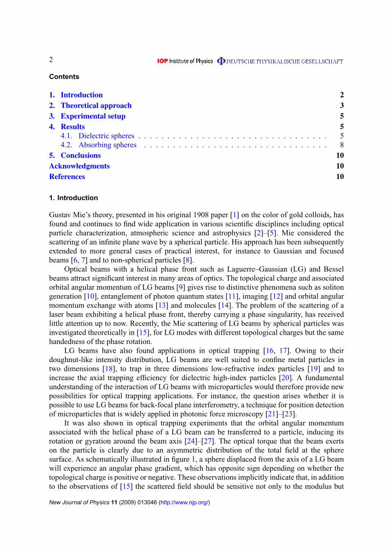
It was also shown in optical trapping experiments that the orbital angular momentumassociated with the helical phase of a LG beam can be transferred to a particle, inducing itsrotation or gyration around the beam axis [24]–[27]. The optical torque that the beam exertson the particle is clearly due to an asymmetric distribution of the total field at the spheresurface. As schematically illustrated in figure 1, a sphere displaced from the axis of a LG beamwill experience an angular phase gradient, which has opposite sign depending on whether thetopological charge is positive or negative. These observations implicitly indicate that, in additionto the observations of [15] the scattered field should be sensitive not only to the modulus but
New Journal of Physics 11 (2009) 013046 (http://www.njp.org/)
3
m=0
x
y
0
2π
m=1
x
y
02π
m=–1
x
y
Figure 1. A sphere is displaced from the optical axis (z) along the x-directionfor a Gaussian beam (m = 0) and for LG beams with m = +1 and −1. The phasefronts of the beams are shown in grayscale (from 0 to 2π the color changesfrom white to black). x is not a preferential direction in space with respect to thephase front of the LG beam, since the phase is periodic and its absolute valueis arbitrary. For a Gaussian beam the phase front is plane and there is no phasegradient. A LG beam has an angular phase gradient which has different signdepending on the sign of the topological charge.
also to the sign of the phase rotation. Previous studies have shown agreement between theoryand experiment for the case of optically trapped particles [28, 29].
Here, we show the effect of the spiral phase structure of a LG beam on the Miescattering. In particular, we address the question whether the analysis of the scattered field(i.e. without observing the movement of an optically trapped particle due to the transfer ofangular momentum) would enable us to distinguish the sign of the phase dislocation, as onewould expect based on the arguments given above. We study the scattering from dielectric (non-absorbing) spheres and from metallic (strongly absorbing) spheres by varying both the modulusand the sign of the topological charge of the LG beam.
2. Theoretical approach
Our approach to the calculation of the scattering from an arbitrary focused beam on a sphericalparticle of arbitrary radius and refractive index is outlined in the following. We calculatethe forward-scattered (FS) field and, by using an algorithm developed for position detectionapplications, we compute the response of a quadrant photodetector when the scattering sphereis moved off the optical axis. Details can be found in [30].
The incident beam is focused by an aplanatic lens producing a convergent spherical wave,which propagates to a diffraction-limited axial image. The aperture of the lens is taken as theentrance pupil of the optical system. A condenser lens collects the incident and FS fields. Aposition detector, located at a plane conjugated to the back-focal plane of the condenser lens,is used to quantify the variations in the total scattered field. The detector consists of foursegments (A, B, C and D; see figure 2) with axes x and y. The intensities recorded on eachsegment are combined to give displacement signals corresponding to the directions x and y(x = (A + D) − (B + C) and y = (A + B) − (C + D)).
New Journal of Physics 11 (2009) 013046 (http://www.njp.org/)
4
+1
0
–1
xyzSLM Pinhole
Laser
CMOS
Lamp
DM
DM
L
L
CCD
100xNA 1.0
60xNA 1.4
Piezo stage Sample
x
y
AB
C D
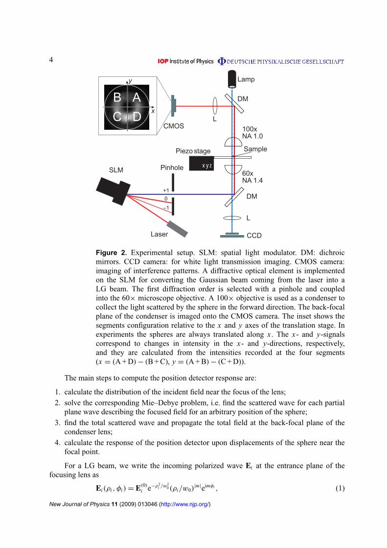
Figure 2. Experimental setup. SLM: spatial light modulator. DM: dichroicmirrors. CCD camera: for white light transmission imaging. CMOS camera:imaging of interference patterns. A diffractive optical element is implementedon the SLM for converting the Gaussian beam coming from the laser into aLG beam. The first diffraction order is selected with a pinhole and coupledinto the 60× microscope objective. A 100× objective is used as a condenser tocollect the light scattered by the sphere in the forward direction. The back-focalplane of the condenser is imaged onto the CMOS camera. The inset shows thesegments configuration relative to the x and y axes of the translation stage. Inexperiments the spheres are always translated along x . The x- and y-signalscorrespond to changes in intensity in the x- and y-directions, respectively,and they are calculated from the intensities recorded at the four segments(x = (A + D) − (B + C), y = (A + B) − (C + D)).
The main steps to compute the position detector response are:
1. calculate the distribution of the incident field near the focus of the lens;2. solve the corresponding Mie–Debye problem, i.e. find the scattered wave for each partial
plane wave describing the focused field for an arbitrary position of the sphere;3. find the total scattered wave and propagate the total field at the back-focal plane of the
condenser lens;4. calculate the response of the position detector upon displacements of the sphere near the
focal point.
For a LG beam, we write the incoming polarized wave Ei at the entrance plane of thefocusing lens as
Ei(ρi , φi) = E(0)
i e−ρ2i /w2
0(ρi/w0)|m|eimφi , (1)
New Journal of Physics 11 (2009) 013046 (http://www.njp.org/)
5
where E(0)
i describes the polarization of the incident field, assumed always linear, ρi and φi arethe polar coordinates at the objective entrance and w0 is the beam waist. The integer index m isthe topological charge of the beam.
We verified our numerical algorithms by comparing the calculated response of the positiondetector with the results of [15] and found good agreement for the predicted behavior for metalparticles. The numerical results corresponding to our experiments are presented in section 4.
3. Experimental setup
We investigated experimentally the Mie scattering of a focused LG beam by dielectric andmetallic microspheres in a FS geometry. The experimental setup is shown schematically infigure 2. A LG beam was generated by converting the Gaussian beam coming from a fiberlaser (λ = 1064 nm, linearly polarized) using diffractive optical elements (DOEs) implementedon a spatial light modulator (SLM) (Hamamatsu) [31]. The first diffraction order was selectedusing a pinhole and coupled by a dichroic mirror (DM) into a 60× objective (oil immersion,NA = 1.4, Nikon). The dynamic implementation of DOEs enabled us to switch between LGbeams with different topological charge without changing the alignment of the beam and, inparticular, keeping its focus always at the same position. This ensured that, for each sphere, wecompare the FS with different beams under the same conditions. As the topological charge mof the beam is changed, the spiral structure is modified and as a consequence the radius of theannular high-intensity distribution changes. In particular, the radius of the high-intensity ring inthe focal plane is proportional to the topological charge m [32]. In our experiments the modulusof the topological charge was varied between |m| = 1 and |m| = 8, and the radius of the high-intensity region increased from 0.9 to 3.1 µm. A 100× objective (water immersion, NA = 1.00,Olympus) was used as condenser lens to collect the FS light. The back-focal plane of thecondenser was imaged by a lens (L) on a CMOS camera (Silicon Video). The sample plane wasimaged on a CCD camera (DVC); the second DM transmitted white light for illumination of thesample, and directed the FS laser radiation on the CMOS camera. The video frames acquiredwith the CMOS camera were analyzed to quantify the variations in the FS field distributionupon particle displacement. To this aim, four detector segments were defined as described insection 2 (see also figure 2) and the corresponding x- and y-signals were computed from thevideo frames.
The aqueous suspension of microparticles was injected between two glass coverslips. Weused the spheres that were adhering to the glass coverslip as probes. The sample was mounted ona xyz piezo translation stage (Piezosystem Jena) to scan the probes through the focused beam.In all the experiments, x is the direction of translation of the particle and y is the directionorthogonal to it. These are not preferential directions in space with respect to the phase front ofthe LG beam (see figure 1), since the phase is periodic and its absolute value is arbitrary. Theresults obtained by translating the sphere along x are therefore valid in general.
4. Results
4.1. Dielectric spheres
First, we investigated the effect of the modulus of the topological charge on dielectric particles.We used silica microspheres of radius rs = 0.5 µm (Bangs Laboratories). The particle size iscomparable with the wavelength of light in the medium, and therefore with the waist w0 of
New Journal of Physics 11 (2009) 013046 (http://www.njp.org/)

6
y
x
y
x
(a)
(b)
m = 0
x/r = 0.5s
m = 1
= 0.5x/rs
m = 2
x /r = 0.5s
m = 1 m=–1
x /r = 0.5s x/r = 0.5s
Figure 3. A dielectric sphere with radius rs = 0.5 µm is displaced off-axis inthe x-direction. (a) Intensity distribution of the scattered field for x/rs = 0.5,for a Gaussian beam (m = 0) and LG beams with m = 1 and 2. The effect ofscanning the sphere through the beam is shown in movie 1 (442 kB, MOV): fora Gaussian beam the fringes move parallel to the direction of translation, x . Fora LG beam the fringes move along a diagonal in the x–y plane. (b) Intensitydistribution of the scattered field for x/rs = 0.5 for LG beams with m = +1and −1. When the sphere is scanned through the beam, the intensity patternmoves along opposite diagonals in the x , y plane, depending on the sign ofthe topological charge, as shown in movie 2 (326 kB, MOV). Both movies areavailable from stacks.iop.org/NJP/11/013046/mmedia.
the focused beam. The numerical simulations were performed on particles with a refractiveindex nsilica = 1.5 and using an effective NA for the lens to account for the partial filling of theobjective’s back-aperture (NA ∼ 0.5).
The most remarkable effect observed in the Mie scattering of a LG beam with topologicalcharge m 6= 0 is that for a displacement of the scatterer along the x-direction, the total scatteredfield changes also in the y-direction. The simulations also revealed this property of the scatteredfield, which was already predicted in [15] for metal spheres.
Figure 3(a) shows the intensity patterns recorded on the CMOS camera upon displacementof a sphere along the x-direction (x/rs = 0.5) for different values of the topological change,m = 0, 1 and 2. When the sphere is off-axis, for a Gaussian beam (m = 0) the interferencefringes in the back-focal plane move off-center, parallel to the direction of translation of theparticle. For a LG beam with m = 1 or 2, the high-intensity region of the interference patternmoves at an angle with the direction of displacement. The corresponding movie (movie 1,available from stacks.iop.org/NJP/11/013046/mmedia) illustrates this effect: the high-intensitypart of the interference fringes for m = 1 and 2 is moving along a diagonal in the x , y plane.This effect is due to the phase front of the LG beam, as schematically represented in figure 1: thephase of a Gaussian beam (topological charge m = 0) is mirror symmetric with respect to anydirection orthogonal to the optical axis (e.g. x), but this is not the case for a LG beam (m 6= 0).
To investigate the effect of the handedness of the helical phase front, we then inverted thesign of the topological charge of the incident beam. Figure 3(b) shows that the high-intensityregion of the interference pattern moves along two opposite diagonals in the x , y plane form = 1 and −1, an effect which is also clearly visible in movie 2.
To quantify the changes in the spatial distribution of the scattered field we calculatedfrom the video frames the position signals as outlined in section 3. Figure 4 compares the
New Journal of Physics 11 (2009) 013046 (http://www.njp.org/)
7
–0.5 0 0.5
–0.5
0
0.5 m = 1
–0.5 0 0.5–0.4
–0.2
0
0.2m = 2
–0.5 0 0.5–1
0
1m = 1
–0.5 0 0.5–0.2
0
0.2m = 2
–0.5 0 0.5–1
0
1m = 0
xy
–0.5 0 0.5–1
0
1m = 0
x/rs x/rs
x/rs x/rs
x/rs x/rs
x/rs x/rs
x/rs x/rs
Sig
nals
(au
)S
igna
ls (
au)
Sig
nals
(au
)S
igna
ls (
au)
Sig
nals
(au
)
Sig
nals
(au
)S
igna
ls (
au)
Sig
nals
(au
)S
igna
ls (
au)
Sig
nals
(au
)
xy
(a)
–0.5 0 0.5
–0.5
0
0.5 m = –1
–0.5 0 0.5–1
0
1 m = –1
(b)
–0.5 0 0.5
–0.5
0
0.5 m = 1
–0.5 0 0.5–1
0
1m = 1
xy
xy
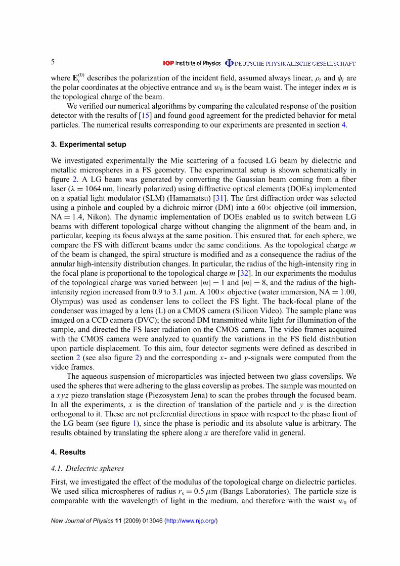
Figure 4. x- and y-signals for a dielectric sphere (rs = 0.5 µm) as the particleis translated along x . The left column shows the experimental results (x : circlesand y: stars) obtained for beams with different modulus of the topologicalcharge (a) and for LG beams with different sign of the charge (b). The rightcolumn presents the corresponding simulations (x : solid line and y: dashedline). For a Gaussian beam the y-response is zero (no cross-talk); for a LGbeam (m = 1, 2), the y-response can also be measured, as predicted by thesimulations. For opposite values of the topological charge (m = 1 and −1) thex-response is unchanged, whereas the y-response changes sign.
New Journal of Physics 11 (2009) 013046 (http://www.njp.org/)

8
y
x
y
x
(a)
(b)
m = 0
x /r = 0.6s
x /rs x /rs
x /rs x /rs x /rs
m = 1
= 0.6
m = 6
= 0.6
m = 8
= 0.6
m = 8
= 0.6
m =–8
= 0.6
Figure 5. A metal sphere with radius rs = 3.5 µm is displaced from the centerof the beam in the x-direction. (a) Intensity distribution of the scattered beamwhen the sphere is positioned at x/rs = 0.5 for a Gaussian beam (m = 0) andLG beams with m = 1, 6 and 8. For m = 0 and for small values of m, thedoughnut radius is much smaller than the radius of the sphere, so that theincident beam is completely blocked and almost no intensity is detected for smalldisplacements (−0.5 < x/rs < 0.5). For m > 6 the doughnut radius becomescomparable with the particle radius. An interference pattern is recorded, witha strong displacement in the y-direction. This effect is shown in movie 3, wherethe particle is scanned through the beam (372 kB, MOV). (b) Effect of the signof the topological charge: the y-component of the intensity pattern moves inopposite directions for m = 8 and −8. The effect of scanning the sphere throughthe beam is illustrated in movie 4 (238 kB, MOV). Both movies are availablefrom stacks.iop.org/NJP/11/013046/mmedia.
experimental x- and y-signals (left column) with the ones obtained by the numerical simulations(right column). The main features observed in the experiments are captured by the simulations.In particular, figure 4(a) shows that for a Gaussian beam (m = 0) the y-signal is negligibleand only an x-response is observed. For a LG beam with m = 1 or 2, a strong y-response isalso measured, corresponding to the diagonal displacement of the intensity pattern showed infigure 3(a). We also note that for m = 1 the slope of the x-signal near x/rs = 0 has opposite signthan that for m = 0, and the sign of the slope is conserved for m = 2. The change in the slope ofthe x-response can be ascribed to the change in size of the doughnut with increasing topologicalcharge: for m = 0 the radius of the Gaussian spot is comparable with the sphere radius; m = 1corresponds to the cross-over to a range where the beam radius is larger than the sphere radius.
The effect of changing the sign of m is shown in figure 4(b). For m = 1 and −1 thex-response is unchanged, whereas the slope of the y-response near x/rs = 0 changes sign.
4.2. Absorbing spheres
We also studied how the modulus and sign of the topological charge of the incident beam affectthe scattered field for the case of absorbing particles. We used gold-coated polystyrene sphereswith radius rs = 3.5 µm (Microparticles GmbH). The numerical simulations were performedassuming a refractive index ngold = 0.503 + i4.923 and NA ∼ 0.5.
Figure 5(a) shows the intensity patterns recorded on the CMOS camera upon displacementof the sphere along the x-direction for m = 0 (Gaussian beam), 1, 6 and 8. For m = 0
New Journal of Physics 11 (2009) 013046 (http://www.njp.org/)
9
–0.5 0 0.5
m = 0
x /rs x /rs
x /rs x /rs
x /rs x /rs
x /rs x /rs
x /rs x /rs
Sig
nals
(au
)S
igna
ls (
au)
Sig
nals
(au
)S
igna
ls (
au)
Sig
nals
(au
)
Sig
nals
(au
)S
igna
ls (
au)
Sig
nals
(au
)S
igna
ls (
au)
Sig
nals
(au
)–0.5 0 0.5
m = 1
–0.5 0 0.5
m = 6
–0.5 0 0.5
m = 8
–0.5 0 0.5–1
0
1m = 0
–0.5 0 0.5–1
0
1m = 1
–0.5 0 0.5–1
0
1m = 6
–0.5 0 0.5–1
0
1m = 8
–0.5 0 0.5
m =–8
–0.5 0 0.5–1
0
1m =–8
xy
xy
–1
0
1
–1
0
1
–1
0
1
–1
0
1
–1
0
1
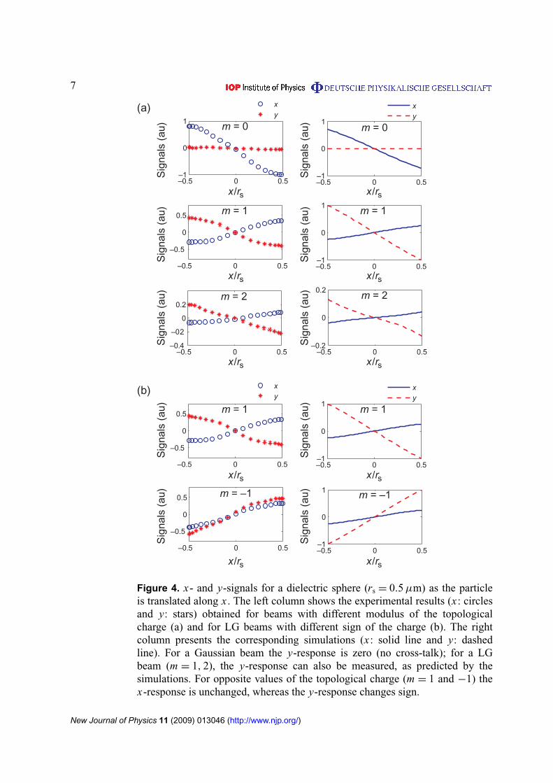
Figure 6. x- and y-signals for a metal sphere with radius rs = 3.5 µm scannedalong the x-direction. The left column shows the experimental results (x : circlesand y: stars) and the right column presents the corresponding simulations(x : solid line and y: dashed line). For m = 0 and 1 both position signals arenegligible, because the particle blocks the incident beam. For larger doughnutsize (m = 6 and 8) a x-response is measured for a displacement along x , butmost remarkably an even bigger y-component is observed. When the sign of mis reversed, the y-response changes sign as predicted by the simulations.
(w0 = 0.7 µm) and for LG beams with small values of m, the radius of the doughnut is muchsmaller than the sphere radius. Hence, the incident beam is completely reflected when thesphere is on-axis, and almost no scattered intensity is detected in the forward direction. Evenfor small displacements of the sphere (−0.5 < x/rs < 0.5) the incident beam remains blocked.For a LG beam with m > 6 the doughnut radius becomes comparable with the particle radius,
New Journal of Physics 11 (2009) 013046 (http://www.njp.org/)
10
and an interference pattern can now be recorded at the detector plane. Large displacementsof the intensity pattern in the y-direction are observed when the sphere is translated off-axis(x/rs = 0.6), as illustrated in movie 3 (available from stacks.iop.org/NJP/11/013046/mmedia),where the sphere is scanned through the beam. In figure 5(b), the effect of the sign of thetopological charge is shown: the intensity pattern moves in opposite directions along y for LGbeams with m = 8 and −8 as illustrated in movie 4.
Figure 6 compares the position signal obtained in the experiments (left column) with thosefrom the simulations (right column). For a Gaussian beam and for LG beams with topologicalcharge up to m = 5 (only m = 0 and 1 are shown in the figure) a low scattered intensity isdetected, and only for large off-axis displacements of the particle (x/rs > 0.5), i.e. when a partof the incident beam is unblocked. For LG beams with m > 6 the slope of the responses aroundx/rs = 0 becomes nonzero (for m = 6 the radius of the doughnut is r I max = 2.7 µm). Also inthe case of metal spheres a strong y-response is measured which, notably, is larger than thex-response. Like for the case of dielectric spheres, a change in the sign of the topological chargeleaves the slope of the x-response unchanged, while the y-response changes sign (see m = 8 and−8 in the figure).
5. Conclusions
The scattering of a LG beam by a sphere generates a field that is sensitive both to the modulusand the sign of the topological charge of the incident beam. This sensitivity manifests itselfwhen the sphere is displaced off the beam axis, and it can be studied qualitatively by measuringthe spatial distribution of the scattered field. We investigated this effect for dielectric and metalspheres in focused LG beams through experiments and numerical simulations.
Our experiments indicate that, in the case of dielectric particles, there is a significant cross-talk between the position signals obtained with a quadrant detector configuration. However,there is a range where the signals change linearly with the sphere displacement. The methodfor inferring the position of a particle from the quadrant detector signals is beyond the scope ofthe present work, and will be addressed elsewhere. These observations show the potential forposition detection of dielectric particles using LG beams.
Acknowledgments
GV thanks Gregory Kozyreff for many useful discussions. VG is supported by a Rubicon grantof the Netherlands Organization for Scientific Research (NWO) and by the InteruniversityCardiology Institute of the Netherlands (ICIN). This research was supported in part by theSpanish Ministry of Education and Science (Grant No. NAN2004-09348-C04-02), by theDepartament d’Universitats, Recerca i Societat de la Informació, and by the European SocialFund.
References
[1] Mie G 1908 Beiträge zur Optik trüber Medien, speziell kolloidaler Metallösungen Ann. Phys., Lpz. 25377–445
[2] Born M and Wolf E 1999 Principles of Optics 7th edn (Cambridge: Cambridge University Press)[3] Kerker M 1969 The Scattering of Light and Other Electromagnetic Radiation (New York: Academic)[4] van de Hulst H C 1981 Light Scattering by Small Particles (New York: Dover)
New Journal of Physics 11 (2009) 013046 (http://www.njp.org/)
11
[5] Goody R M and Yung Y L 1989 Atmospheric Radiation: Theoretical Basis (New York: Oxford UniversityPress)
[6] Gouesbet G, Grehan G and Maheu B 1985 Scattering of a Gaussian beam by a Mie scatter center using aBromwich formalism J. Opt. 16 83–93
[7] Barton J P, Alexander D R and Schaub S A 1988 Internal and near-surface electromagnetic fields for aspherical particle irradiated by a focused laser beam J. Appl. Phys. 64 1632–9
[8] Han Y P, Grehan G and Gouesbet G 2003 Generalized Lorenz–Mie theory for a spheroidal particle withoff-axis Gaussian-beam illumination Appl. Opt. 42 6621–9
[9] Allen L, Barnett S M and Padgett M 2003 Optical Angular Momentum (Bristol: Institute of PhysicsPublishing)
[10] Desyatnikov A S, Torner L and Kivshar Y S 2005 Optical Vortices and Vortex Solitons Progress in Opticsvol 47 ed E Wolf (Oxford: Pergamon)
[11] Mair A, Vaziri A, Weihs G and Zeilinger A 1990 Entanglement of the orbital angular momentum states ofphotons Nature 412 313–6
[12] Torner L, Torres J P and Carrasco S 2005 Digital spiral imaging Opt. Express 13 873–81[13] Jáuregui R 2004 Rotational effects of twisted light on atoms beyond the paraxial approximation Phys. Rev. A
70 033415[14] Alexandrescu A, Cojoc D and Di Fabrizio E 2006 Mechanism of angular momentum exchange between
molecules and Laguerre–Gaussian beams Phys. Rev. Lett. 96 243001[15] van de Nes A S and Török P 2007 Rigorous analysis of spheres in Gauss–Laguerre beam Opt. Express 15
13360–74[16] Molloy J E and Padgett M 2002 Lights, action: optical tweezers Contemp. Phys. 43 241–58[17] Grier D G 2003 A revolution in optical manipulation Nature 424 810–6[18] Sato S, Harada Y and Waseda Y 1994 Optical trapping of microscopic metal particles Opt. Lett. 19 1807–9[19] Gahagan K T and Swartzlander G A 1996 Optical vortex trapping of particles Opt. Lett. 21 827–9[20] O’Neil A T and Padgett M J 2001 Axial and lateral trapping efficiency of Laguerre–Gaussian modes in
inverted optical tweezers Opt. Commun. 193 45–50[21] Ghislain L P and Webb W W 1993 Scanning-force microscope based on an optical trap Opt. Lett. 18 1678–80[22] Prälle A, Prummer M, Florin E-L, Stelzer E H K and Hörber J K H 1999 Three-Dimensional high-resolution
particle tracking for optical tweezers by forward scattered light Microsc. Res. Tech. 44 378–86[23] Volpe G, Volpe G and Petrov D 2007 Brownian motion in a nonhomogeneous force field and photonic force
microscope Phys. Rev. E 76 061118[24] He H, Friese M E J, Heckenberg N R and Rubinsztein-Dunlop H 1995 Direct observation of transfer of
angular momentum to absorptive particles from a laser beam with a phase singularity Phys. Rev. Lett. 75826–9
[25] Paterson L, MacDonald M P, Arlt J, Sibbett W, Bryant P E and Dholakia K 2001 Controlled rotation ofoptically trapped microscopic particles Science 292 912–4
[26] O’Neil A T, MacVicar I, Allen L and Padgett M J 2002 Intrinsic and extrinsic nature of the orbital angularmomentum of a light beam Phys. Rev. Lett. 88 053601
[27] Volpe G and Petrov D 2006 Torque Detection using Brownian Fluctuations Phys. Rev. Lett. 97 210603[28] Simpson N B, Dholakia K, Allen L and Padgett M J 1997 Mechanical equivalence of spin and orbital angular
momentum of light: an optical spanner Opt. Lett. 22 52–4[29] Zhao Y, Edgar J S, Jeffries G D M, McGloin D and Chiu D T 2007 Spin-to-orbital angular momentum
conversion in a strongly focused optical beam Phys. Rev. Lett. 99 073901[30] Volpe G, Kozyreff G and Petrov D 2007 Backscattering position detection for photonic force microscopy
J. Appl. Phys. 102 084701[31] Cojoc D, Garbin V, Ferrari E, Businaro L, Romanato F and Di Fabrizio E 2005 Laser trapping and micro-
manipulation using Laguerre–Gaussian beams Microelectron. Eng. 78–79 125–31[32] Curtis J E and Grier D G 2003 Structure of optical vortices Phys. Rev. Lett. 90 133901
New Journal of Physics 11 (2009) 013046 (http://www.njp.org/)


![MIE Introduction [Demo]](https://static.fdocuments.in/doc/165x107/55a21c041a28ab7d5d8b470c/mie-introduction-demo.jpg)