Megacities Building Sway Considerations in Elevators ... · The building sway analysis refers to an...
15
Megacities Building Sway Considerations in Elevators Design for Mega Tall Buildings Authors: Jaakko Kalliomäki, M.Sc., KONE Corporation Jarkko Saloranta, M. Sc., KONE Corporation / Upwind
Transcript of Megacities Building Sway Considerations in Elevators ... · The building sway analysis refers to an...

MegacitiesBuilding Sway Considerations in Elevators Design for Mega Tall BuildingsAuthors: Jaakko Kalliomäki, M.Sc., KONE Corporation
Jarkko Saloranta, M. Sc., KONE Corporation / Upwind

Jaakko Kalliomaki
10 years of experience with high rise elevator technology. Specialized in system engineering, hoisting technology and building sway.
� Education
� 2003 M.Sc. in Mechanical Engineering, Helsinki University of Technology, Finland
� Work Experience
� 2003 – 2005 Mechanical Designer, ABB Oy (Drives and Power Electronics), Finland
� 2005 – 2007 Designer, Delta Energy System (Finland) Oy
� 2007 – 2014 (Senior) Chief Design Engineer, KONE Corporation, Finland
� 2014 onward Global Platform Manager (High Rise Platforms), KONE Corporation, Finland
24 October 2017 Confidential | © KONE Corporation2
Authors
� vjhjlv Jarkko Saloranta
More than 10 years of experience in wind engineering. Specialized in numerical models, hoisting systems simulations and building sway.
� Education
� 2006 Master of Science (M.Sc.) in Aeronautics/Aviation/Aerospace Science and Technology, Helsinki University of Technology, Finland
� Work Experience
� 2006 – 2008 PhD Student/Researcher Helsinki University of Technology, Finland
� 2008 – 2010 Design Engineer (numerical models) KONE Corporation, Finland
� 2010 – 2013 Technical Specialist, WinWinD Oy
� 2013 onward Entrepreneur/ Technical Specialist, UpWind (assigned to KONE Corporation)

Understanding sway analysis

Sway analysis
24 October 2017 Confidential | © KONE Corporation4
Sway analysis� The building sway analysis refers to an analysis on the building behavior in
wind conditions by the builder. � It covers many aspects which considerably affect the functionality of the
elevator system in a building. � It may be empirical (wind tunnel based) and theoretical (code based)Frequency/resonance analysis� Due to the nature of elevator systems, the tension in the elevator ropes
changes as a function of the car position in the elevator shaft. Therefore, after certain travel - depending on the properties of the building and elevator - areas where resonance exist cannot be avoided.
� Frequency/resonance analysis by elevator provider tries to determine the location and extension of the problem.

Building Frequency
24 October 2017 Confidential | © KONE Corporation5
� Building frequency is not gained by wind tunnel testing but ratherprovided by the structural engineer, who has to makesimplifications on the building design, which cause deviations in thebuilding frequencies (typically 0…- 20 %).
� The building frequencies can also be estimated. One commonapproximation is 46/H –approximation, where H is the buildingheight.
� Based on actual measurements the frequencies gained byapproximations are not less accurate and the predicted frequenciestend to be lower than the 46/H –approximation. [1].
� In Japan a 67/H –approximation has been adopted based on fieldmeasurements [2].
� Even if uncertainty exists the frequency analysis is an importantpart of the elevator design. It gives an overall understanding of thelocation and extent of the resonance areas.
f=67/H
Figure 1. Measured building frequencies [1] superimposed with 67/H-curve by author.

Wind Response
24 October 2017 Confidential | © KONE Corporation6
� In the along-wind direction the building is not excited at a certain frequency.The amplitude can be significant, but the implications to the elevatorsystems are moderate due to lack of resonance.
� The crosswind response is often dominated by vortex shedding, whichproduces a constant excitation force at a certain frequency. If thisfrequency coincides closely with building natural frequency, the buildingstarts to resonate. If resonance is also present at that point of time with theelevator system, energy accumulates quickly in the elevator ropes resultingin large rope sway amplitudes.
� In building design phase solutions can be find which reduce excitationcaused by the vortex shedding and place it away from the building naturalfrequency at higher wind speeds. Methods include tapering the building,step-backs, changing corner shape and shape variation with height orchanging the dynamic characteristics of the building (including mass,stiffness, mode shapes and damping [1,4].
� If not successful, the behavior of the whole building will be problematic.
Figure 2. Aerodynamic load spectra [3].
Figure 3. Vortex Shedding [3].

Wind Climate Model
24 October 2017 Confidential | © KONE Corporation7
� Typical wind climate models are based primarily on information measured close to the ground level (ca. 10 m)
� Wind loading at higher altitudes is based on modelling rather than measured data. A typical boundary layer model assumes that wind speed increases as a function of altitude. This works if wind is constantly coming from the same direction but e.g. not with thunderstorm downbursts.
� Depending on the used model, the excitations and return periods for higher building movement level can be considerable different.
� Local authorities can also impose requirements, which may not be in line with best available wind data. This can lead to inaccurately estimated wind loads or creation of two parallel set of calculations; one for authorities and other based on best estimate.
Figure 4. Cascading Scales in Meteorology [5,6].
Figure 5. Wind Speed Profiles by Storm Type [5].
Scale [km] Time (Life Span)
MarcoscaleGlobal
4000 -40 000
WesterliesTrade windsLong
waves
MarcoscaleSynoptic
1000 -4000
CyclonesHurricanes
Mesoscale 1 - 1000
Sea/Mountain Breeze
Tornados Thunderstorms
Microscale < 1
Wind gustBuilding corner eddies
Seconds to minutes
Minutes to hours
Days to weeks
Weeks to seasons

Human comfort criteria, building deflections and amplitudes
24 October 2017 Confidential | © KONE Corporation8
� The design of tall buildings is driven by the human comfort criteria in the top floors. � Traditionally, the occupant comfort has been based on 5- and 10-year intervals� Recent trend is towards one-year recurrence as it addresses better the discomfort of regularly occurring event. People tend
to tolerate discomfort felt infrequently for short periods of time, but not as routine occurrences. [4].� Several criteria for building motion exists (i.e. ISO6897-1984, ISO10137-2007, NBCC 1995, AS1170.2, CTBUH, etc.). � These criteria differ in the evaluated recurrence period, vibration they assess (effective versus peak), if vibration frequency
is considered and if the criteria is dependent on the occupancy (office, residential, hotel). � For elevator engineering, the abundance of criteria makes it difficult to know what level of elevator service needs to be
guaranteed at what conditions� During extreme weather the elevators are expected to be parked and therefore the lower thresholds amplitudes have much
more influence on the more common elevator design and operation (e.g. on yearly level).� The accelerations for the comfort evaluation are either estimates based on aerodynamic databases (or building codes) or
wind tunnel testing. The wind tunnel testing show better the effect of architecture of the surrounding building and the localwind climate, but contains still uncertainties in particular the wind climate model and structural properties of the building.
� During elevator design, the details how the building wind response was achieved is often not available. � The elevator design has to be based on the excitation levels and return periods given in the wind analysis report even if it is
known not to cover all aspects relevant to elevator design. � The data obtained from the builder is an important parameter to help scale the severity of the sway problems.

Annoyance factor
24 October 2017 Confidential | © KONE Corporation9
� The return period associated with strong winds and buildingmovement does not give a comprehensive view of what is theireffect on the elevator service.
� In a typical office building the active working hours can be expectedto last approximately 10 h on 250 days per year, which representroughly 30 % of the total. Outside this time frame, breaks inelevator service would cause less annoyance.
� Furthermore, of those working hours up-peak, lunch peak anddown peak are most critical during which speed reduction of theelevator would be most inconvenient, but these represent onlyaround 6% of total time. This means that the probability of speedreduction of short duration (typically < 15 min) associated in windconditions like thunderstorms (refer to Figure 6) have lowprobability of generating substantial annoyance.
� In residential buildings, hotels, hospitals and other buildingsexpecting 24h service in climate conditions where gale winds oflonger duration are dominant (see Figure 7), similar return periodcould be perceived much more annoying.
Figure 6. Time history of acceleration during thunderstorm [7].
Figure 7. Building response during typhoon [8]
~ 10 min
~ 15 h

Resonance calculation

Resonance Calculation
24 October 2017 Confidential | © KONE Corporation11
� Various papers focusing on elevator rope-sway simulations/studies have been presented in scientificpublications, which can be classified in three main approaches:– Analytical Method
– Finite Element Method (FEM)– Finite Difference (FD) method
� FEM is widely used in the studies of vibrating structures and can be considered as norm in structuralengineering, but it often leads to heavy simulations.
� In FD-based methods the derivatives of the governing rope-sway equations are directly approximated andsimple time-marching techniques can be used.
� The three different approaches are briefly described and a comparison of results of the models is presented.

Sway Models
24 October 2017 Confidential | © KONE Corporation12
Analytical model� The model was presented in an article in Elevator World magazine [8]. Modal
superposition approach and Lagrange energy-method are used to derive thedynamic equation for vibrating ropes and the arisen equation is solvedanalytically.
� One of the critical simplifications is that the tension is assumed to beconstant in rope (value is the tension at rope half length).
� Results provided by this model are considered inaccurate. This is clearlydemonstrated by comparison with other models.
� It would be possible to improve the accuracy of the predicted resonances ofthis model by modifying the rope tension, when the natural frequencies of therope are computed.
� A significant drawback of this model is that the vibrating rope shape and themaximum amplitude are frozen in time, so travelling waves or sway build-upcannot be analyzed with this method.
Figure 8. An example of results provided by these tools,with input parameters:
Travel = 350 [m]Sway frequency of building = 0.200 [Hz]Compensation rope weight per unit length = 2.06 [kg/m]Number of compensation ropes = 4Compensation rope tension weight mass = 3500 [kg]
Sway Models
24 October 2017 Confidential | © KONE Corporation13
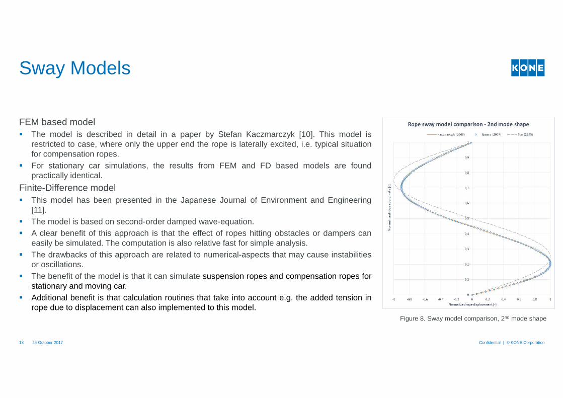
FEM based model� The model is described in detail in a paper by Stefan Kaczmarczyk [10]. This model is
restricted to case, where only the upper end the rope is laterally excited, i.e. typical situationfor compensation ropes.
� For stationary car simulations, the results from FEM and FD based models are foundpractically identical.
Finite-Difference model� This model has been presented in the Japanese Journal of Environment and Engineering
[11].� The model is based on second-order damped wave-equation.� A clear benefit of this approach is that the effect of ropes hitting obstacles or dampers can
easily be simulated. The computation is also relative fast for simple analysis.� The drawbacks of this approach are related to numerical-aspects that may cause instabilities
or oscillations.� The benefit of the model is that it can simulate suspension ropes and compensation ropes for
stationary and moving car.� Additional benefit is that calculation routines that take into account e.g. the added tension in
rope due to displacement can also implemented to this model.Figure 8. Sway model comparison, 2nd mode shape


Reference
24 October 2017 Confidential | © KONE Corporation15
[1] Denoon, R., Scott, D., & Strobel, K. (2012). Challenging Paradigms in the Wind Engineering Design of Tall Buildings. CTBUH. Shanghai. Retrieved from http://www.ctbuh.org/LinkClick.aspx?fileticket=XvYDmYzaDkw%3d&tabid=3967&language=en-US
[2] Kwok, K., Tse, K., & Campbell, S. (2011). Field Measurements of Dynamic Properties of High-Rise Buildings. Advances in Structural Engineering Vol. 14 No. 6 , 1107 - 1128.
[3] Dragovich, D., & Boggs, J. (2006). The Nature of Wind Loads and Dynamic Response.
[4] Burton, M., Kwok, K., & Abdelrazaq, A. (2015). Wind-Induced Motion of Tall Buildings: Designing for Occupant Comfort. Internation Journal of High-Rise Buildings, Vol 4, No 1, March, 1-8.
[5] Galsworthy, J., Phillips, D., Irwin, P., & Xie, J. (2012). Design of Asian Supertall Buildings for Wind. CTBUH. Shanghai. Retrieved from http://www.ctbuh.org/LinkClick.aspx?fileticket=jM5oKP%2bzRj8%3d&tabid=3967&language=en-US
[6] Horstmeyer. S. (2004). Scales of Atmospheric Motion. Retrieved 18.9. 2017 from http://www.shorstmeyer.com/msj/geo165/scales.html
[7] Denoon, R. (2015). Wind Engineering Challenges in the UAE. Retrieved from The Institution of Structural Engineers: https://www.istructe.org/downloads/near-you/uae/dubai-istructe-feb-2015_roy-denoon.pdf
[8] Denoon, R. (2014). Wind Engineering Beyond the Code. Retrieved from Structural Engineers Association of Ohio: http://seaoo.org/downloads/NCSEA_Conf_Info/2014_ncsea_slides._roy_denoon.pdf
[9] Sun, L. (1995). Building sway and elevator rope vibration. Elevator World, March, 133-135.
[10] Kaczmarczyk, S. (2008). Dynamic Response of Elevator Ropes in Buildings under Wind Loading. Symposium on the Mechanics of Slender Structures (MoSS). Thessalonika, Greece.
[11] Kimura, H., Ito, H., & Nakagawa, T. (2007). Vibration Analysis of Elevator Rope – Forced Vibration of Rope with Time-Varying Length. Journal of Environment and Engineering.Vol. 2, No 1, 87-96.