Manual Mantenimiento Celdas 8BK20
16
s Medium-Voltage Switchgear Type 8BK20 Switchgear up to 24 kV with Withdrawable Circuit-Breakers Air-Insulated, Metal-Enclosed, Metal-Clad, Single/Double Busbar Maintenance Instructions Order No.: 8BX 3220-3BA00 Issue 2000-11 Revision 01 Figure 1 Switchpanels 8BK20 (example) 1 Preventive maintenance ........................ 3 1.1 Inspection schedule ............................... 3 1.2 Cleaning .................................................... 4 1.2.1 Removing and fitting the air filter ............ 4 1.2.2 Cleaning agents ........................................ 6 1.3 Lubrication ............................................... 7 1.4 Checking the voltage indication and the coupling section ........................ 8 2 Corrective maintenance ..................... 10 2.1 Releasing the door interlock ............... 10 2.2 Emergency operation of the withdrawable section .......................... 11 2.3 Replacing fuse links ............................. 12 3 Testing the switching devices with open door ...................................... 13 3.1 Circuit-breaker ...................................... 13 3.2 Vacuum switch ..................................... 14 4 Appendix .................................................16 4.1 Replacement of parts ............................16 4.2 Disposal ..................................................16 4.3 Illustrations ........................................ 16 Contents Follow the operating instructions for the equipment installed and Catalog HA 25.21.
-
Upload
alejandro-garay-moreno -
Category
Documents
-
view
1.197 -
download
103
Transcript of Manual Mantenimiento Celdas 8BK20
s
Medium-Voltage SwitchgearType 8BK20 Switchgear up to 24 kV with Withdrawable Circuit-BreakersAir-Insulated, Metal-Enclosed, Metal-Clad, Single/Double Busbar
Maintenance Instructions Order No.: 8BX 3220-3BA00Issue 2000-11 Revision 01
Figure 1 Switchpanels 8BK20 (example)
1 Preventive maintenance ........................ 3
1.1 Inspection schedule ............................... 31.2 Cleaning .................................................... 41.2.1 Removing and fitting the air filter ............ 41.2.2 Cleaning agents ........................................ 61.3 Lubrication ............................................... 71.4 Checking the voltage indication
and the coupling section ........................ 8
2 Corrective maintenance ..................... 10
2.1 Releasing the door interlock ............... 102.2 Emergency operation of the
withdrawable section .......................... 112.3 Replacing fuse links ............................. 12
3 Testing the switching deviceswith open door ...................................... 13
3.1 Circuit-breaker ...................................... 133.2 Vacuum switch ..................................... 14
4 Appendix .................................................16
4.1 Replacement of parts ............................164.2 Disposal ..................................................164.3 Illustrations ........................................16
Contents
Follow the operating instructions for the equipment installed and Catalog HA 25.21.
2 20001101 ∗ MAINTENANCE INSTRUCTIONS ∗ 8BX 3220-3BA00
Alle Rechte vorbehalten. All rights reserved. Siemens AG 2000
Qualified personnelas used in these instructions or the warning information on the product itself means persons who are familiar with installation, assembly, commissioning, operation and maintenance of the product and have the appropriate qualifications for their work, such as
l Training and instruction or authori-zation to switch on, switch off, earth and identify circuits and equipment / systems in accordance with the relevant safety standards.
l Training or instruction in accordance with the relevant safety standards in relation to care and use of appropriate safety equipment.
l First-aid training.
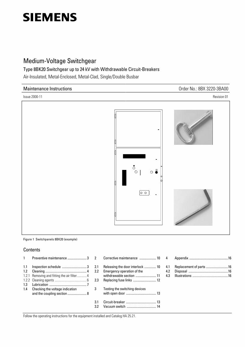
Signal terms and definitions:
DANGERas used in these instructions and in the warning information on the products themselves means that death, serious bodily injury or substantial damage to property will occur if the corresponding precautionary measures are not taken.
CAUTIONas used in these instructions and the warning information on the products themselves means that minor bodily injury or damage to property may occur if the corresponding precautionary measures are not taken.
WARNINGas used in these instructions and the warning information on the products themselves means that death, serious bodily injury or substantial damage to property may occur if the corresponding precautionary measures are not taken.
Noteas used in these instructions indicates important information on the product or the relevant part of the instructions to which particular attention must be paid.
Introduction and application of a quality management system for theMedium-Voltage Division in accordance with DIN EN ISO 9001 and DIN EN ISO 14001 Quality systems - Model for quality assurance in design, development, production, installation and servicing.Certification of the quality management systemby DQS (German Association for the Certification of Quality Management Systems)DQS registr. number: 3473-02
Evaluation the technical testing station by DATech (German Accreditation Body for Technology) in accordance with DIN EN 45 001 and accreditation of the technical testing station for the testing areas High-Voltage Switching Devices and Switchgear by DATech as Testing Laboratory Switchgear Factory Frankfurt/M., Siemens AGDAR (German Accreditation Council) registr. number: DAT-P-013/92-00and as PEHLA Testing Laboratory Frankfurt/M. DAR registr. number: DAT-P-013/92-50
1992
1995
Siemens AGPower Transmission and Distribution Group
Medium-Voltage DivisionSwitchgear Factory Frankfurt

8BX 3220-3BA00 ∗ MAINTENANCE INSTRUCTIONS ∗ 20001101 3
Maintenance
WARNINGDuring operation ofelectrical equipment andswitchgear certain parts arelive and hazardous voltagesare therefore present, andmechanical componentsmay move quickly, evenremotely controlled.
Non-observance of thesafety instructions andwarnings can result insevere personal injury orproperty damage.
Only qualified personnelshould work on or in thevicinity of this equipmentand switchgear.
Such personnel mustbecome thoroughly familiarwith all warnings containedin these instructions.
The successful and safe op-eration of this switchgear isdependent on proper trans-port, storage, installationand erection and also ondiligent operation andmaintenance.
It is advisable to call on thesupport of the competentSiemens Service Centresfor planning, erection, com-missioning andmaintenance work.
Setting-up and operation ofthis switchgear are conditio-nal on observance of thefollowing DIN VDE / IECspecifications:DIN VDE 0100 / IEC 60364;DIN VDE 0101;DIN VDE 0105.
DANGERHigh voltage!Touching the live parts willbe lethal or will result inserious bodily injury.The equipment may beoperated only by qualifiedpersonnel who are familiarwith the instructions andwho observe the warninginformation in particular.
1 Preventive maintenance
1.1 Inspection schedule(maintenance is recommendedaccording to following intervals)
Maintain and care for the installedequipment, e.g. circuit-breakers,voltage transformers, meters,protective devices etc., in accordancewith the information contained in therespective operating instructions.• Commercially available tools are
adequate for maintenance.• Perform commissioning in
accordance with the installationinstructions after maintenance.
• Maintenance and care are requiredat shorter intervals (at the user’sdiscretion) in dusty conditions or ifthe air is extremely humid andcontaminated.
• Grease make-proof earthingswitches after 500 switchingoperations: Refer to OperatingInstructions "Lubricants " 8BX 3150-3GA00.
• Irrespective of the regularmaintenance, the cause of faults andshort circuits must be determinedimmediately and any damaged partsmust be replaced.
CAUTIONDo not climb onto thepanels!
Annually (at the user’s discretion)
• General visual inspection fordamage, dust deposits, moistureand partial discharge noises.
• Check whether accessories arecomplete and in good condition (alsocentral service truck).
Every five years
WARNINGIsolate the switchgear,secure it against reclosing,check safe isolation fromsupply, earth and short-circuit the outgoing feeders(DIN VDE 0105). The busbarmust also be earthed andshort-circuited if it isplanned to work in thebusbar compartment.
Ensure that the bolts at the currenttransformer are tight (Figure 2).
Every ten years (or at the user’sdiscretion)
WARNINGIsolate the switchgear,secure it against reclosing,check safe isolation fromsupply, earth and short-circuit the outgoing feeders(DIN VDE 0105). The busbarmust also be earthed andshort-circuited if it isplanned to work in thebusbar compartment.
• Perform test operations with thecircuit-breaker, vacuum switch andearthing switch.
• Clean the switchpanels, check high-voltage connections (terminals).
• Check the operating point of thelimit switches for the motoroperating mechanisms of thewithdrawable sections.
• Check the switchpanel functions andput the switchgear back intooperation.
Current transformer
Ensure that the bolts are tight
Figure 2 Ensuring that the bolts at the current transformer are tight

4 20001101 ∗ MAINTENANCE INSTRUCTIONS ∗ 8BX 3220-3BA00
1.2 Cleaning
1.2.1 Removing and fitting the airfilter
Air filter in the lower part of the high-voltage door (Figure 3)
• Undo the fixing bolts of the tensionframe
• Remove the tension frame• Clean the filter• Refit in reverse order.
Air filter in bottom duct (Figure 4)
Air filter on the roof (Figures 5, 6, 7)• Remove the withdrawable section.
Panels with open-circuit ventilation
Removal• Undo the three nuts (6, Figure 5;
accessible in the switchcompartment) that support the airfilter directly behind the rear wall ofthe low-voltage compartment(Figure 5), hold the air filter whenundoing the last nut.
• Turn the detached longitudinal sidedown and remove the filter.
Installation• Align the air filter in the switch
compartment so that the longitudinalside with the three holes is inclinedand points at the low-voltagecompartment.
• Place the longitudinal side withoutholes on the roof above the verticalpartition wall.
• Turn the longitudinal side with thethree holes to the top and bolt ittight.
Air filterFixing bolts Tension frame
Figure 3 Air filter in the lower part of the high-voltage door (front view)
Undo 4 fixing bolts
Grip for pulling out
Figure 4 Air filter in the bottom duct
Air filter
Partition wall between busbar and switch compartment.
Roof plate
Door of low-voltage compartment
Rear wall of low-voltage compartment
Fixing nut for air filter
Figure 5 Air filter in the panel cooled by free convection

8BX 3220-3BA00 ∗ MAINTENANCE INSTRUCTIONS ∗ 20001101 5
Panels with open-circuit ventilation
Removal• Undo six fixing bolts (Figure 6) and
pull the air filter out downwards.
Installation• Align the filter− by the holes for the fixing bolts and− according to the mounting position:
plate with holes for fixing boltshorizontally, frame with wire-clothslightly inclined to the right side-wall.
• Insert the air filter from the bottomto the top and bolt tight.
Maintain the motor of the fan unit asdescribed in the associatedinstructions "Ventilator/Fans"!
• Insert the withdrawable section andmove it to the connected position.
Fixing bolts of air filter Thermostat
Fan module
Air filter
Figure 6 Fan unit in the switch compartment of the panel with forced ventilation (view from the floor to the top)
Pressure relief flap of busbar compartment
Fan module
Figure 7 Roof of a panel with forced ventilation
6 20001101 ∗ MAINTENANCE INSTRUCTIONS ∗ 8BX 3220-3BA00
1.2.2 Cleaning agents
WARNINGTo protect employees andthe environment, alwaysfollow the instructions onthe cleaning agents!
ARAL 4005 or HAKU 1025/90 (containshydrocarbons), brushes, cleaning rags,vacuum cleaner.
WARNING
Fire hazard!
No smoking!
Observe productdescriptions and safetyinstructions!
CAUTIONCleaning agents containinghydrocarbons must not beused for electricallystressed insulation parts,(e.g. epoxy resin).
HAKU 5067 (contains alcohol) or waterwith household detergent is a suitablecleaning agent for epoxy resin parts.

8BX 3220-3BA00 ∗ MAINTENANCE INSTRUCTIONS ∗ 20001101 7
1.3 Lubrication
Grease immediately after cleaningaccording to Operating Instructions"Lubricants "8BX 3150-3GA00.
Grease the central service truckspindle.
8 20001101 ∗ MAINTENANCE INSTRUCTIONS ∗ 8BX 3220-3BA00
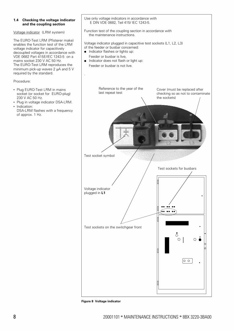
1.4 Checking the voltage indicatorand the coupling section
Voltage indicator (LRM system)
The EURO-Test LRM (Pfisterer make)enables the function test of the LRMvoltage indicator for capacitivelydecoupled voltages in accordance withVDE 0682 Part 415E/IEC 1243-5 on amains socket 230 V AC 50 Hz.The EURO-Test LRM reproduces theminimum pick-up waves 2 µA and 5 Vrequired by the standard.
Procedure:
• Plug EURO-Test LRM in mainssocket (or socket for EURO-plug)230 V AC 50 Hz.
• Plug in voltage indicator DSA-LRM.• Indication:
DSA-LRM flashes with a frequencyof approx. 1 Hz.
Use only voltage indicators in accordance with E DIN VDE 0682, Teil 415/ IEC 1243-5.
Function test of the coupling section in accordance with the maintenance instructions.
Voltage indicator plugged in capacitive test sockets (L1, L2, L3)of the feeder or busbar concerned:V Indicator flashes or lights up: Feeder or busbar is live,V Indicator does not flash or light up: Feeder or busbar is not live.
.
Test sockets on the switchgear front
Cover (must be replaced after checking so as not to contaminatethe sockets)
Voltage indicatorplugged in L1
Reference to the year of the last repeat test
Test socket symbol
Test sockets for busbars
Figure 8 Voltage indicator

8BX 3220-3BA00 ∗ MAINTENANCE INSTRUCTIONS ∗ 20001101 9
Coupling sectionThe function must be repeatedlytested and certified during inspections,latest after 6 years.
• The user of the switchgear isresponsible for:
− Performance of the supervision− Documentation of the supervision− Repairing of defective / faulty
permanent voltage indicationsystems
− Storage of documentation.
• The measured insulation resistanceand current values described have tobe documented in the report andconfirmed by signature.
• In case of deviations, the repair, ifapplicable the replacement of parts,must be arranged with repeat test.
The following tests are performed onthe complete coupling section -knowing the momentary phase-to-earth voltage - in all three phases:
• Measuring the insulation resistanceon the complete coupling section(incl. coaxial cable connection),Figure 9.
− Measuring point: Test sockets onthe switchgear front, Figure 8.
− Test voltage: 90VThe test is passed if the measuredinsulation resistance is > 20 MΩ.
• The phase of the measuring pointcarrying the measuring voltage mustbe earthed through a resistance andan ammeter with a total impedanceof: 2 MΩ + 3% or 1600 pF, and thecurrent must be measured(fígure10).
− Measuring point: Test sockets onthe switchgear front, Figure 8.
− The test is passed if the measuredcurrent is >= 3.2 µA.
− Note:These tests can be performedduring switchgear operation as afunction test!Voltage measurements at the testsocket are not suitable for thesechecks!
− On electronic measuringinstruments, observe the position ofthe earth side of the measuringinstrument!
Recommended: Insulation meter type ISOWID B 4101, make: Siemens
Figure 9 Measuring the insulation resistance at the test socket
Recommended: Multimeter MA 4E, make: METRAWATT GmbH with LRM interface test adapter (1600 pF) make: PFISTERER
Figure 10 Measuring the current at the test socket

10 20001101 ∗ MAINTENANCE INSTRUCTIONS ∗ 8BX 3220-3BA00
2 Corrective maintenance
2.1 Releasing the door interlock incase of emergency
WARNING
The interlock of the door ofthe high-voltagecompartment should onlybe released if thewithdrawable sectioncannot be racked to thedisconnected position aftera fault and the damagecannot be rectified in anyother way. Safetymeasures: Isolate theswitchgear in accordancewith DIN VDE 0105.
Procedure:Perform steps 1 to 4 as shown inFigure 11.
Insert the hexagonal socket key (DIN 911-4) in the opening and turn it clockwise until the set screw falls out on the inside.
Insert the double-bit key in the lock and turn it counter.clockwise by 90°.
Firmly tighten the set screw again after repair.
Close the eathing switch if necessary.
s
d
f
a
Lift the door knob to the stop and open the door.
Figure 11 Releasing the door interlock in case of emergency

8BX 3220-3BA00 ∗ MAINTENANCE INSTRUCTIONS ∗ 20001101 11
2.2 Emergency operation of thewithdrawable section
WARNINGSafety measures: Beforestarting to work, isolate theswitchgear, secure itagainst reclosing, checksafe isolation from supply(DIN VDE 0105), earth andshort-circuit it.Disconnect control voltages.
Procedure:• Switching device OFF.• Release the interlock of the door of
the switch compartment asdescribed in section 2.1 foremergencies, and open the door.
• After completion of the emergencyoperation, refit the set screw (Figure11, no. 4) of the door interlock onthe door.
Emergency: Releasing theelectromagnetic interlock
The withdrawable section must bemoved from the connected to thedisconnected position even though theauxiliary voltage for releasing theelectromagnetic interlock is notavailable.• Mounting location: When viewing
from the front, the electromagnet isfitted on the withdrawable sectionon the left side in the traversemechanism (Figure 12).
• Perform steps 1 to 5 as shown inFigure 12.
Insert the double-bit key in the lock.
90°
Remove the lower cover.
A
B
Housing with the coil of the electromagnet
Core of the electromagnet Interlock lever
Section A-B
Manually slide the the core of the electromagnet into the coil (in the housing), hold it and
Latch for the withdawable section - door interlock
simultaneously press down the latch for the withdrawable section - door interlock with a screwdriver and turn the double-bit key by 90° counter-clockwise.
Push the hand crank onto the hexagon, turn it counter-clockwise as far as it will go and remove it.
Turn the double-bit key counter-clockwise by 90° and remove it.
Each time when turning the double-bit key with the HV door open, pressdown the latch for the withdrawable section - door interlockusing a screwdriver.
CAUTION
s
d
f
a
g
Figure 12 Releasing the electromagnetic interlock of the withdrawable section

12 20001101 ∗ MAINTENANCE INSTRUCTIONS ∗ 8BX 3220-3BA00
Emergency:Motor operating mechanism inintermediate position
The withdrawable section must beracked out of a position between theconnected and the disconnectedposition, even though the auxiliaryvoltage for racking the withdrawablesection by motor is not available(Figure 13)
2.3 Replacing fuse links
CAUTIONSuitable are fuse links withdimensions in accordancewith DIN 43 625 and"medium" type striker pin inaccordance with IEC 282-1.
• Move the withdrawable section ontothe central service truck asdescribed in the OperatingInstructions, Section 2.4.1, unlockthe central service truck from thepanel.
• Remove the fuse links.
CAUTIONThe fuse links may be hot!
• Turn out one clip on each end(Figure 14), push down thehorizontally arranged fuse links outof the holders and remove them tothe side.
• Select and align the new fuse links:The arrow must point at thetripping/signalling mechanism
• Push the new fuse links into theholders and secure with the clips(Figure 14).
Insert a screwdriver through the opening of the carriage mechanism, release the latch . . .
. . . and simultaneously insert a second screwdriver through the opening to turn the toothed wascher until the withdrawable section reaches one of the two limitpositions .
Figure 13 Emergency operation of the motor operating mechanism in intermediate position
Clip
Figure 14 Replacing fuse links (example: withdrawable section with vacuum switch)

8BX 3220-3BA00 ∗ MAINTENANCE INSTRUCTIONS ∗ 20001101 13
3 Testing the switchingdevices with opendoor
3.1 Circuit-breaker
Charging the closing spring by hand
CAUTIONThe circuit-breaker may beoperated only with the origi-nal crank (Figure 15), inorder to avoid injuriescaused by the motorstarting suddenly.
Procedure:• Insert the hand crank through the
opening (Figure 16) directly onto thecircuit-breaker operating mechanism.
• Turn it clockwise until the symbol"Spring charged" appears in theinspection window.
• If the power supply for the motorreturns during charging, there is nodanger to the operator as the handcrank turns counter-clockwise withno load.
• Remove the hand crank.
Closing and opening• Locally using mechanical means,
with pushbuttons;− operate the pushbuttons "ON" and
"OFF" directly on the withdrawablesection (Figure 16);if necessary,charge the closing spring by handwhen the low-voltage plugconnector is disconnected from thewithdrawable section.
• Electrically from the control roomand, if necessary, locally withpushbuttons.
If the control voltage fails, the circuit-breaker can always be switched offmechanically (see above).
Hand crank
Hand crank coupling
Figure 15 Hand crank for circuit-breaker
Opening for the hand crank to charge the closing spring
"OFF" pushbutton "ON" pushbutton
Closing spring charged
Circuit-breaker ON
Closing spring not charged
Circuit-breaker OFF
Operating cycle counter00123 00123
Figure 16 Control elements and indicators for circuit-breaker 3AH

14 20001101 ∗ MAINTENANCE INSTRUCTIONS ∗ 8BX 3220-3BA00
3.2 Vacuum switch
Closing with pushbuttons:Operate "ON" pushbutton (Figure 17).
Closing with the hand crank:
CAUTIONThe vacuum switch may beoperated only with the origi-nal crank (Figure 18) inorder to avoid injuriescaused by the motorstarting suddenly.
• Insert the hand crank through theopening directly onto the switchoperating mechanism.
• Turn it clockwise until the symbol"Spring charged" appears in theinspection window.
• Remove the hand crank.
Opening:Operate "OFF" pushbutton (Figure 17).
Opening for hand crank for closing
"OFF" pushbutton"ON" pushbutton
Vacuum switch ON
Fuse links "tripped"
Fuse links "ready for operation"
Vacuum switch OFF
Figure 17 Control elements and indicators for vacuum switch 3CG
Hand crank for closing
Hand crank coupling
Figure 18 Hand crank for vacuum switch

8BX 3220-3BA00 ∗ MAINTENANCE INSTRUCTIONS ∗ 20001101 15
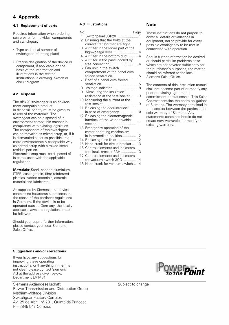
4 Appendix
4.1 Replacement of parts
Required information when orderingspare parts for individual componentsand switchgear:
• Type and serial number ofswitchgear (cf. rating plate)
• Precise designation of the device orcomponent, if applicable on thebasis of the information andillustrations in the relatedinstructions, a drawing, sketch orcircuit diagram.
4.2 Disposal
The 8BK20 switchgear is an environ-ment compatible product.In disposal, priority must be given tore-use of the materials. Theswitchgear can be disposed of inenvironment compatible manner incompliance with existing legislation.The components of the switchgearcan be recycled as mixed scrap, or, if itis dismantled as far as possible, in amore environmentally acceptable wayas sorted scrap with a mixed-scrapresidual portion.Electronic scrap must be disposed ofin compliance with the applicableregulations.
Materials: Steel, copper, aluminium,PTFE, casting resin, fibre-reinforcedplastics, rubber materials, ceramicmaterial and lubricants.
As supplied by Siemens, the devicecontains no hazardous substances inthe sense of the pertinent regulationsin Germany. If the device is to beoperated outside Germany, the locallyapplicable laws and regulations mustbe followed.
Should you require further information,please contact your local SiemensSales Office.
4.3 Illustrations
No. Page 1 Switchpanel 8BK20 .................... 1 2 Ensuring that the bolts at the
current transformer are tight ....... 3 3 Air filter in the lower part of the
high-voltage door ....................... 4 4 Air filter in the bottom duct ......... 4 5 Air filter in the panel cooled by
free convection ........................... 4 6 Fan unit in the switch
compartment of the panel withforced ventilation ........................ 5
7 Roof of a panel with forcedventilation.................................... 5
8 Voltage indicator ........................ 8 9 Measuring the insulation
resistance at the test socket ....... 910 Measuring the current at the
test socket ................................. 911 Releasing the door interlock
in case of emergency ................ 1012 Releasing the electromagnetic
interlock of the withdrawablesection ...................................... 11
13 Emergency operation of themotor operating mechanismin intermediate position.............. 12
14 Replacing fuse links ................... 1215 Hand crank for circuit-breaker .... 1316 Control elements and indicators
for circuit-breaker 3AH............... 1317 Control elements and indicators
for vacuum switch 3CG ............. 1418 Hand crank for vacuum switch... 14
Note
These instructions do not purport tocover all details or variations inequipment, nor to provide for everypossible contingency to be met inconnection with operation.
Should further information be desiredor should particular problems arisewhich are not covered sufficiently forthe purchaser’s purposes, the mattershould be referred to the localSiemens Sales Office.
The contents of this instruction manualshall not become part of or modify anyprior or existing agreement,commitment or relationship. This SalesContract contains the entire obligationsof Siemens. The warranty contained inthe contract between the parties is thesole warranty of Siemens. Anystatements contained herein do notcreate new warranties or modify theexisting warranty.
Suggestions and/or corrections
If you have any suggestions forimproving these operatinginstructions, or if anything in them isnot clear, please contact SiemensAG at the address given below,Department EV MS1
Siemens AktiengesellschaftPower Transmission and Distribution GroupMedium-Voltage DivisionSwitchgear Factory CorroiosAv. 25 de Abril. n° 201, Quinta da PrincesaP.– 2845 547 Corroios
Subject to change