Logstrup Modular System - Unit Concept
48
Transcript of Logstrup Modular System - Unit Concept
Logstrup Modular System Pls contact [email protected] for more details and pricing
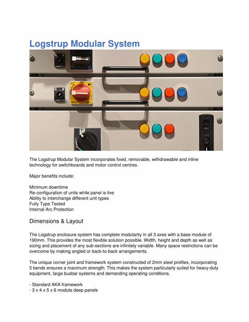
Logstrup Modular System
The Logstrup Modular System incorporates fixed, removable, withdrawable and inline
technology for switchboards and motor control centres.
Major benefits include:
Minimum downtime
Re-configuration of units while panel is live
Ability to interchange different unit types
Fully Type Tested
Internal Arc Protection
Dimensions & Layout
The Logstrup enclosure system has complete modularity in all 3 axes with a base module of
190mm. This provides the most flexible solution possible. Width, height and depth as well as
sizing and placement of any sub-sections are infinitely variable. Many space restrictions can be
overcome by making angled or back-to-back arrangements.
The unique corner joint and framework system constructed of 2mm steel profiles, incorporating
5 bends ensures a maximum strength. This makes the system particularly suited for heavy-duty
equipment, large busbar systems and demanding operating conditions.
- Standard AKA framework
- 3 x 4 x 5 x 6 module deep panels
- Standard sections for shipping which are easy to join on site
- Busbar X-Y or Z plane
- Cableway in front of busbar running throughout the whole length of the panel, top and bottom
- Easy to extend and upgrade
- Front access and rear access
Sizes: X - 5 + 6 Y - 10, 11, 12 Z - 3, 4, 5, 6
Double section of 10m X 12m can be assembled from one framework for shipping as one piece
Partly Built Options
The Logstrup Modular System can be shipped as a flat pack/loose part kits, to build up by the
customer.
An other option is to receive the product partly built. This means that structural parts and main
busbar is built up before departing from Logstrup. Cladding will follow as loose part kit as usual.
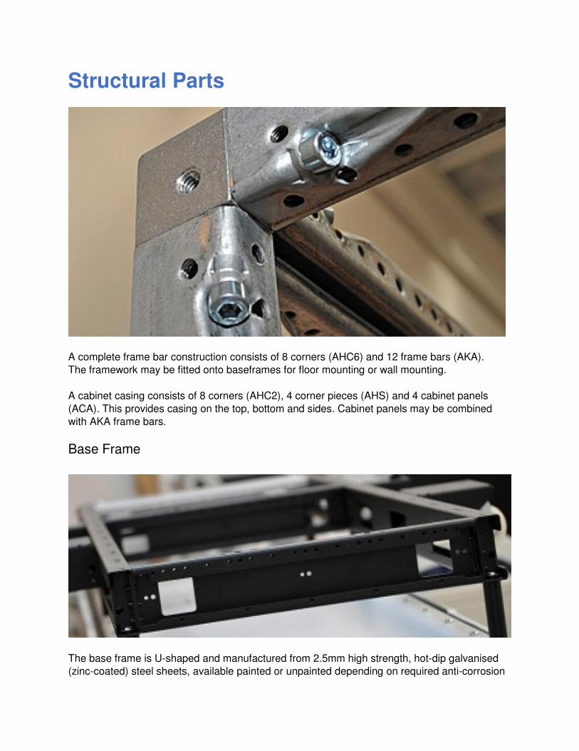
Structural Parts
A complete frame bar construction consists of 8 corners (AHC6) and 12 frame bars (AKA).
The framework may be fitted onto baseframes for floor mounting or wall mounting.
A cabinet casing consists of 8 corners (AHC2), 4 corner pieces (AHS) and 4 cabinet panels
(ACA). This provides casing on the top, bottom and sides. Cabinet panels may be combined
with AKA frame bars.
Base Frame
The base frame is U-shaped and manufactured from 2.5mm high strength, hot-dip galvanised
(zinc-coated) steel sheets, available painted or unpainted depending on required anti-corrosion
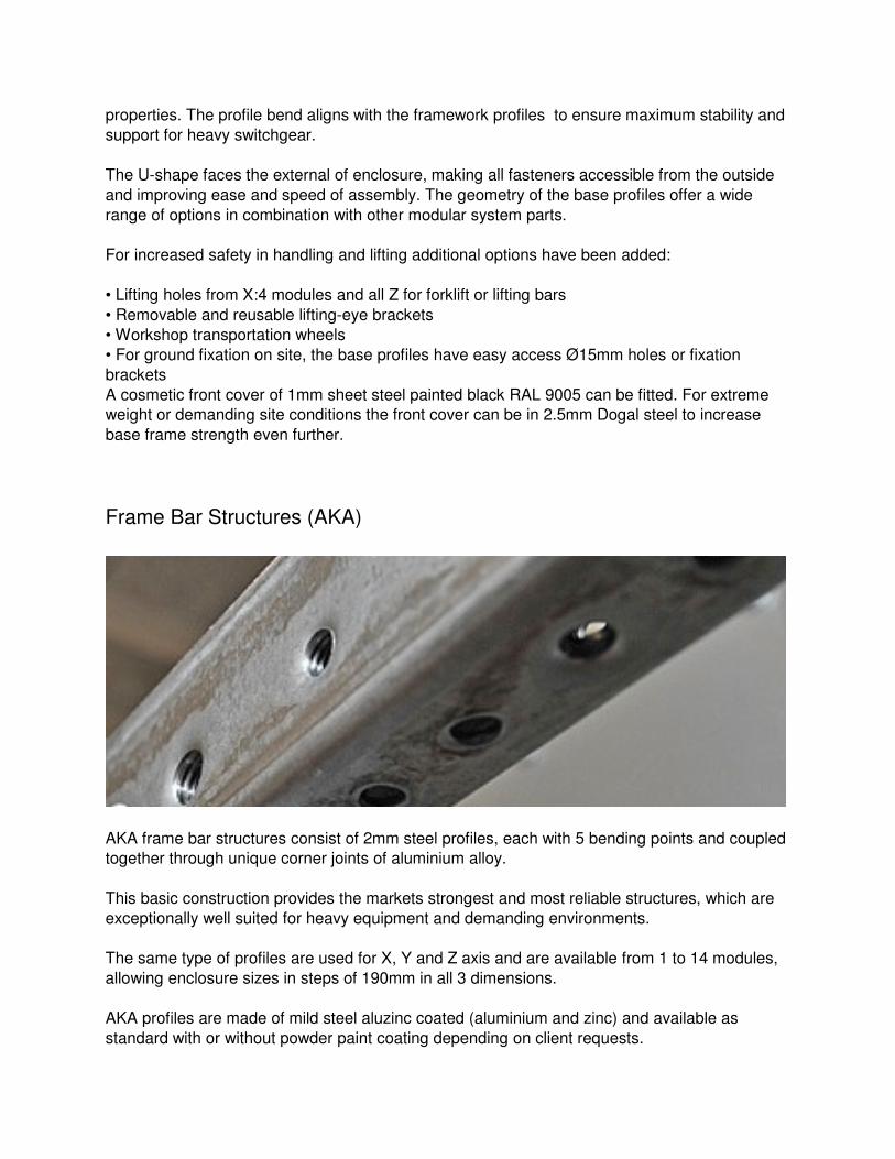
properties. The profile bend aligns with the framework profiles to ensure maximum stability and
support for heavy switchgear.
The U-shape faces the external of enclosure, making all fasteners accessible from the outside
and improving ease and speed of assembly. The geometry of the base profiles offer a wide
range of options in combination with other modular system parts.
For increased safety in handling and lifting additional options have been added:
• Lifting holes from X:4 modules and all Z for forklift or lifting bars
• Removable and reusable lifting-eye brackets
• Workshop transportation wheels
• For ground fixation on site, the base profiles have easy access Ø15mm holes or fixation
brackets
A cosmetic front cover of 1mm sheet steel painted black RAL 9005 can be fitted. For extreme
weight or demanding site conditions the front cover can be in 2.5mm Dogal steel to increase
base frame strength even further.
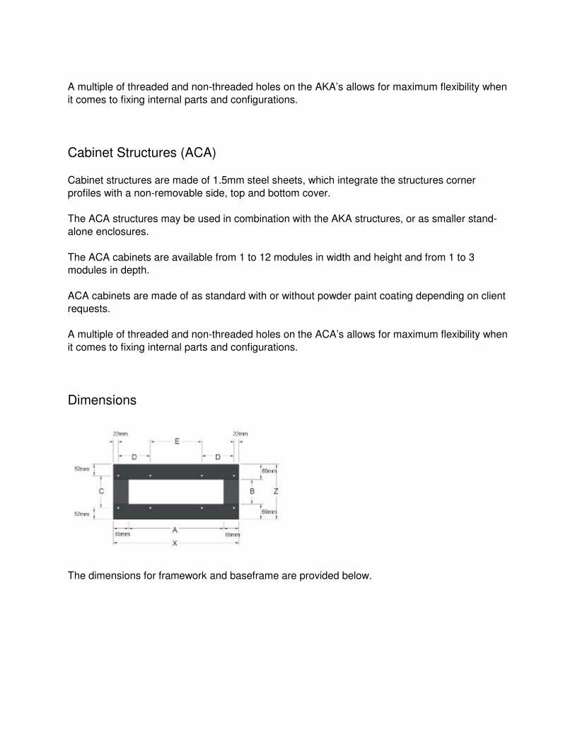
Frame Bar Structures (AKA)
AKA frame bar structures consist of 2mm steel profiles, each with 5 bending points and coupled
together through unique corner joints of aluminium alloy.
This basic construction provides the markets strongest and most reliable structures, which are
exceptionally well suited for heavy equipment and demanding environments.
The same type of profiles are used for X, Y and Z axis and are available from 1 to 14 modules,
allowing enclosure sizes in steps of 190mm in all 3 dimensions.
AKA profiles are made of mild steel aluzinc coated (aluminium and zinc) and available as
standard with or without powder paint coating depending on client requests.
A multiple of threaded and non-threaded holes on the AKA’s allows for maximum flexibility when
it comes to fixing internal parts and configurations.
Cabinet Structures (ACA)
Cabinet structures are made of 1.5mm steel sheets, which integrate the structures corner
profiles with a non-removable side, top and bottom cover.
The ACA structures may be used in combination with the AKA structures, or as smaller stand-
alone enclosures.
The ACA cabinets are available from 1 to 12 modules in width and height and from 1 to 3
modules in depth.
ACA cabinets are made of as standard with or without powder paint coating depending on client
requests.
A multiple of threaded and non-threaded holes on the ACA’s allows for maximum flexibility when
it comes to fixing internal parts and configurations.
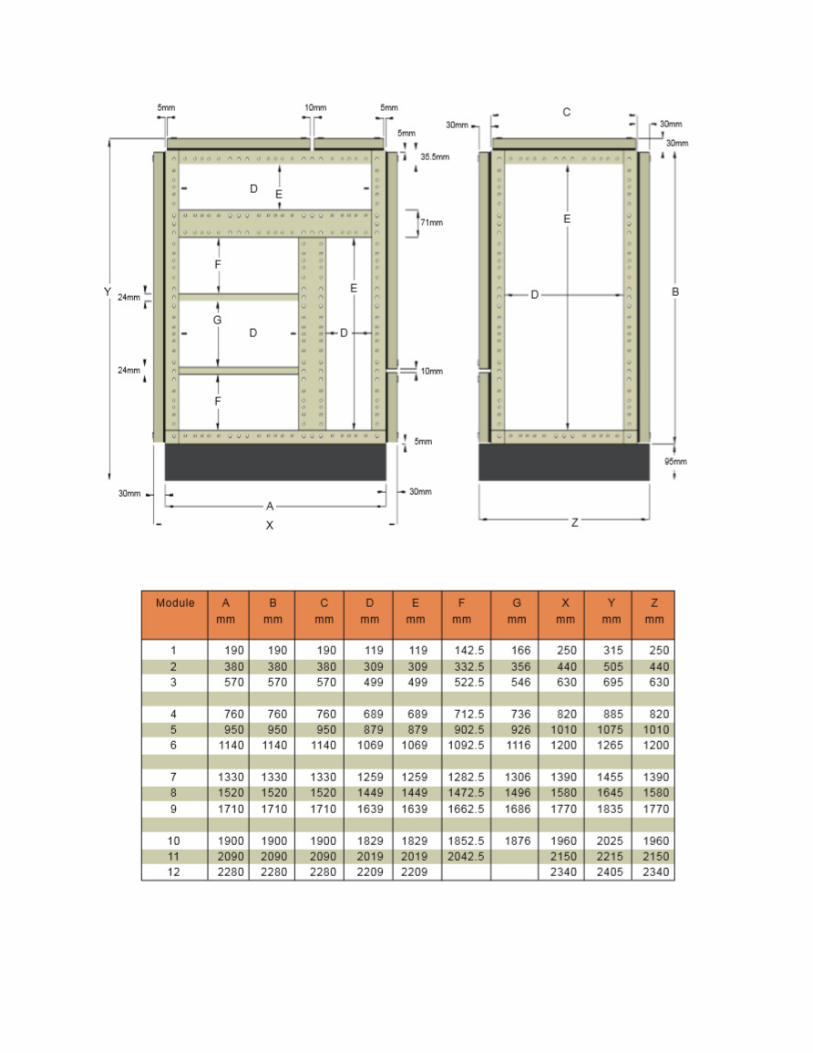
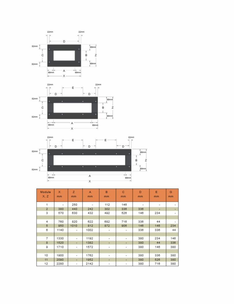
Dimensions
The dimensions for framework and baseframe are provided below.
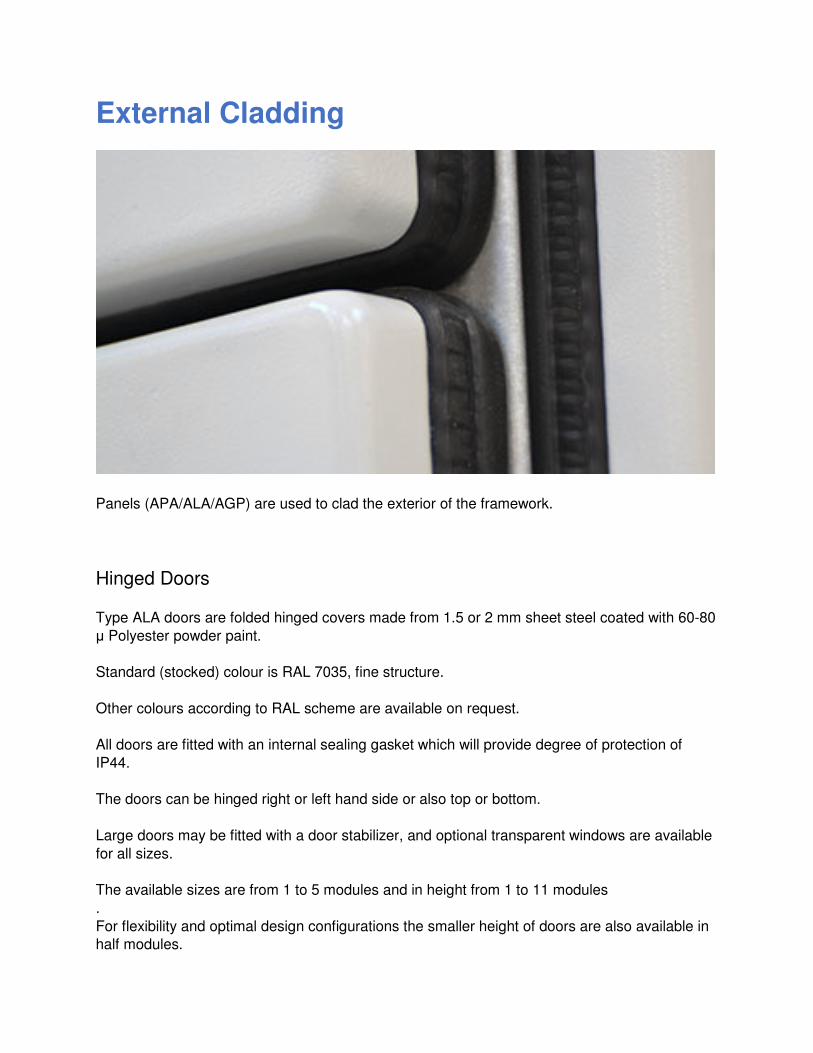
External Cladding
Panels (APA/ALA/AGP) are used to clad the exterior of the framework.
Hinged Doors
Type ALA doors are folded hinged covers made from 1.5 or 2 mm sheet steel coated with 60-80
μ Polyester powder paint.
Standard (stocked) colour is RAL 7035, fine structure.
Other colours according to RAL scheme are available on request.
All doors are fitted with an internal sealing gasket which will provide degree of protection of
IP44.
The doors can be hinged right or left hand side or also top or bottom.
Large doors may be fitted with a door stabilizer, and optional transparent windows are available
for all sizes.
The available sizes are from 1 to 5 modules and in height from 1 to 11 modules
.
For flexibility and optimal design configurations the smaller height of doors are also available in
half modules.
Panels (ALA/APA)
Type APA panels are folded fixed covers made from 1.5 or 2 mm sheet steel coated with 60-80
μ Polyester powder paint.
Standard (stocked) colour is RAL 7035, fine structure.
Other colours according to RAL scheme are available on request.
All APA panels are fitted with an internal sealing gasket which will provide degree of protection
of IP44.
The APA panels are can be fitted horizontally and vertically and range in size from 1.1 module
to 5.11.
The panels can optionally be delivered with louvers IP22 or IP42 for natural ventilation of the
enclosures.
Flat Panels (AGP)
Type AGP plates are flat covers intended to be fitted on the top or rear of enclosures.
AGP plates are made of mild steel aluzinc coated (aluminium and zinc) and available as
standard with or without powder paint coating depending on client requests.
The AGP plates may be fitted with an optional rubber gasket for IP44 protection, and can
optionally be delivered with louvers IP22 for natural ventilation of the enclosures.
Accessories
A wide range of locking devices are available, such as single or 3-point point locks, multiple key
systems or tooling to meet access control requirements.
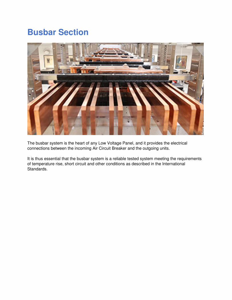
Busbar Section
The busbar system is the heart of any Low Voltage Panel, and it provides the electrical
connections between the incoming Air Circuit Breaker and the outgoing units.
It is thus essential that the busbar system is a reliable tested system meeting the requirements
of temperature rise, short circuit and other conditions as described in the International
Standards.
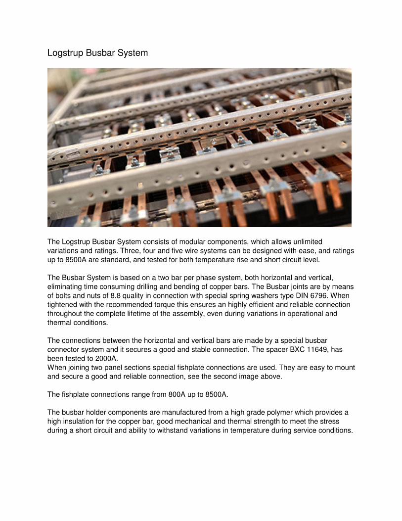
Logstrup Busbar System
The Logstrup Busbar System consists of modular components, which allows unlimited
variations and ratings. Three, four and five wire systems can be designed with ease, and ratings
up to 8500A are standard, and tested for both temperature rise and short circuit level.
The Busbar System is based on a two bar per phase system, both horizontal and vertical,
eliminating time consuming drilling and bending of copper bars. The Busbar joints are by means
of bolts and nuts of 8.8 quality in connection with special spring washers type DIN 6796. When
tightened with the recommended torque this ensures an highly efficient and reliable connection
throughout the complete lifetime of the assembly, even during variations in operational and
thermal conditions.
The connections between the horizontal and vertical bars are made by a special busbar
connector system and it secures a good and stable connection. The spacer BXC 11649, has
been tested to 2000A.
When joining two panel sections special fishplate connections are used. They are easy to mount
and secure a good and reliable connection, see the second image above.
The fishplate connections range from 800A up to 8500A.
The busbar holder components are manufactured from a high grade polymer which provides a
high insulation for the copper bar, good mechanical and thermal strength to meet the stress
during a short circuit and ability to withstand variations in temperature during service conditions.
Resistance
The contact interface between two faces of a busbar joint consists of a large number of
separate point contacts, the area of which increases as more contact pressure is applied and
the peaks are crushed.
There are two main factors which therefore affect the actual interface resistance of the contact
surfaces.
1. The condition of the surfaces.
2. The total applied pressure.
Condition of Copper Surface
The condition of the contact surface of a joint has an important bearing on its efficiency.
The surface of the copper should be flat and clean but needs not to be polished. Machining is
not usually required. Perfectly flat joint faces are not necessary since very good results can be
obtained merely by ensuring that the joint is tight and clean. This is particularly true where
extruded copper is used.
Copper like all other common metals, readily develops a very thin surface oxide film even at
ordinary temperatures and when exposed to air. Therefore it is important to clean the surface to
ensure that the oxide layer is thin enough to be broken as the contact surface peaks deform
when the contact pressure is applied.
Tinning of the contact surfaces is normally unnecessary, although advantages can be gained in
certain circumstances.
If the joint faces are very rough tinning may result in some improvement in efficiency.
Pressure
It has been proved that contact pressure resistance is dependent more on the total applied
pressure than on the area of contact. If the total applied pressure remains constant and the
contact area is varied, as is the case of a switch blade moving between spring loaded contacts,
the total contact resistance is practically constant.
The greater the applied pressure the lower will be the joint resistance and therefore for high
efficiency joints high pressure is usually necessary. This has the advantage that the high
pressure helps to prevent deterioration of the joint.
Joint resistance falls rapidly with increasing pressure, but above a pressure of 15 N/mm2 there
is little further improvement. Certain precautions must be observed to ensure that the contact
pressure is not unduly high, since it is important that the proof stress of the conductor material
or its bolts and clamps is not exceeded.
As a bar heats up under load the contact pressure in a joint with steel bolts tends to increase
because of the difference in expansion coefficients between copper and steel. It is therefore
essential that the initial contact pressure is kept to such a level so that it is not excessive when
at operating temperature. If the elastic limit of the bar is exceeded the joint will have a reduced
contact pressure when it returns to its cold state due to the joint material having deformed or
stretched.
To avoid this A/S Løgstrup - Steel prescribes the use of disc spring washers, (according to DIN
Standard 6796), whose spring rating is chosen to maintain a substantial contact pressure under
cold and hot working conditions.
The torque settings recommended by A/S Løgstrup - Steel, are applicable to high-tensile steel
bolts and nuts with unlubricated threads for normal surface finish.
Configuration
The system consists of modular components which allow unlimited variations. 3, 4, & 5 wire
systems can be created with ease, while the space between phases can be increased to ease
connection to large breakers and facilitate connections of multiple cables.
The busbar support insulators are manufactured from a high grade polymer, which can
withstand all the mechanical and thermal stresses involved. All polymers used in the system are
CFC and halogen free.
Systems up to 8000A can be assembled as standard. A 2 bar, 2x2 bar or 3x2 bar per phase
arrangement is used. This allows connections and extensions to be made without drilling or
bending of the copper.
The high short circuit level of the busbar system and the mechanical robustness of the
enclosures, guarantees a reliable, safe and long lasting system suitable for even the most
demanding environments.
Busbar Ratings
The rating is based on the DIN Standard 43671 and the conditiond as described below.
Rating table for Copper Busbars according to DIN 43671
Copper Specification according to standard EN ISO 10720 / ASTM B272
Rating at 40°C ambient temperature (average temperature over 24 hours : 35°C) and maximum
busbar temperature 120°C.
The ratings are tested values and the tests are performed in a Form 4 type panel with a degree
of protection IP 3X - 4X.
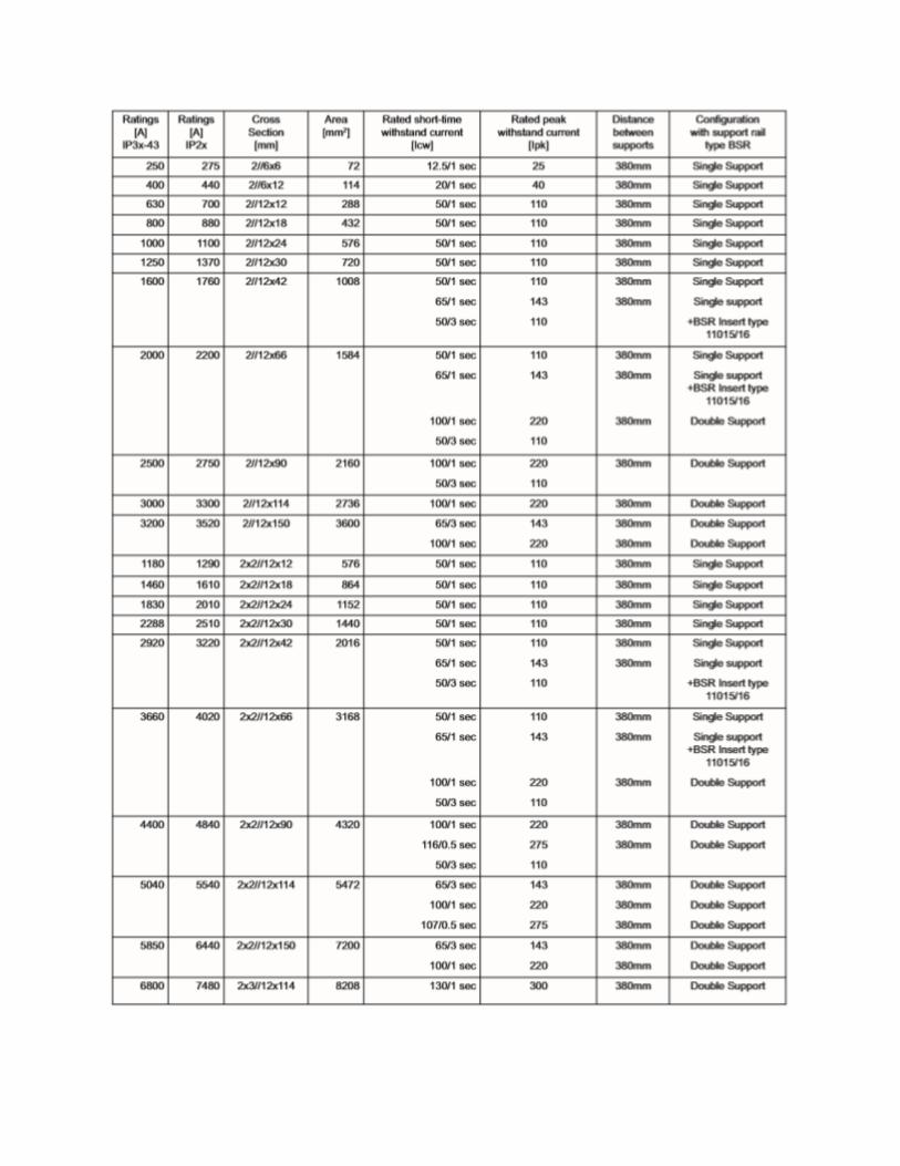
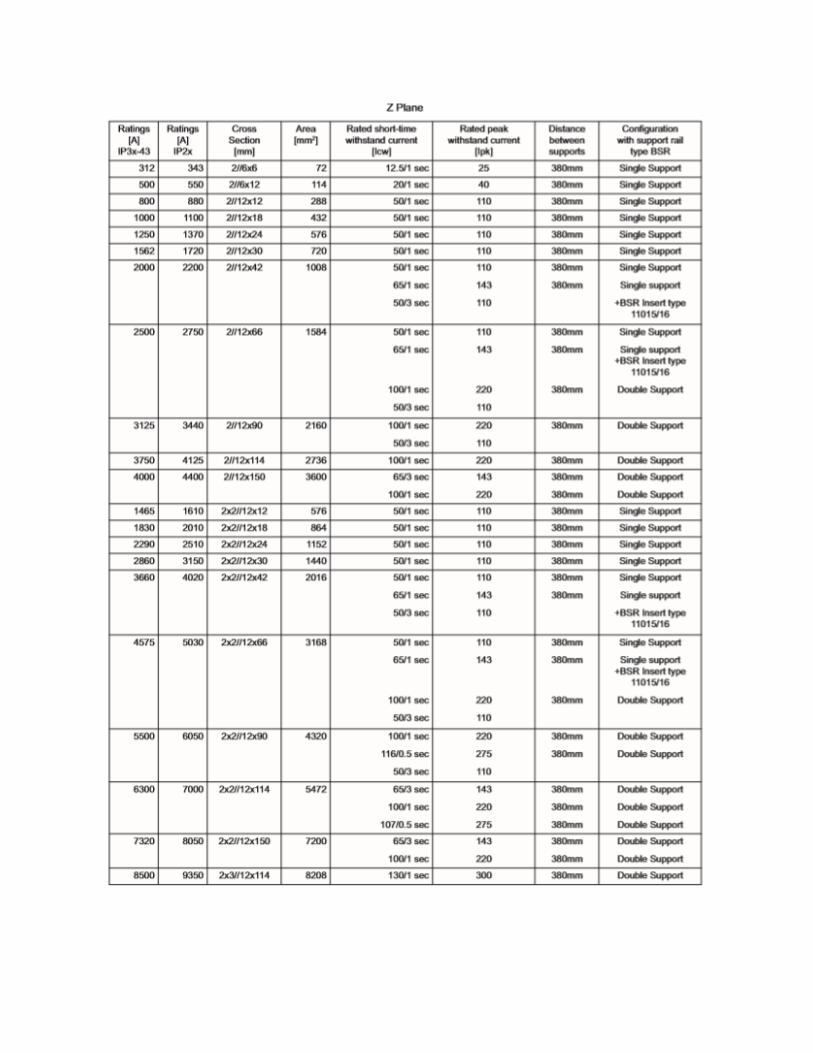
Ratings X/Y & Z Plane:
Rating at 40°C ambient temperature (average temperature over 24 hours : 35°C)
and maximum busbar temperature 120°C.
The ratings are tested values and the tests are performed in a Form 4 type panel with a degree
of protection IP 3X - 4X.
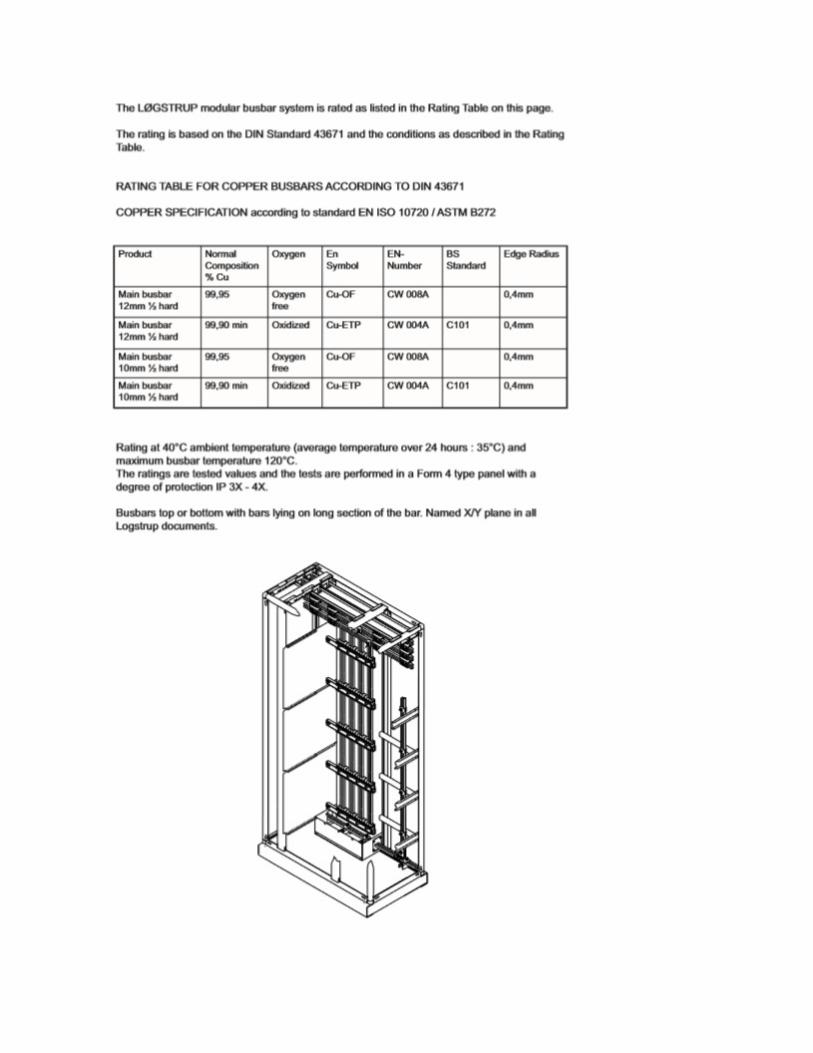
Busbars top or bottom with bars lying on long section of the bar. Named X/Y plane in all
Logstrup documents.
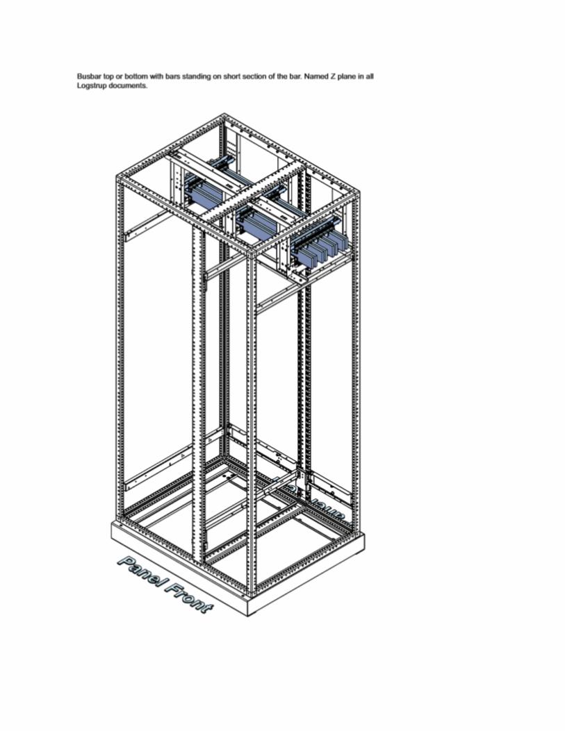
Busbar top or bottom with bars standing on short section of the bar. Named Z plane in all
Logstrup documents.
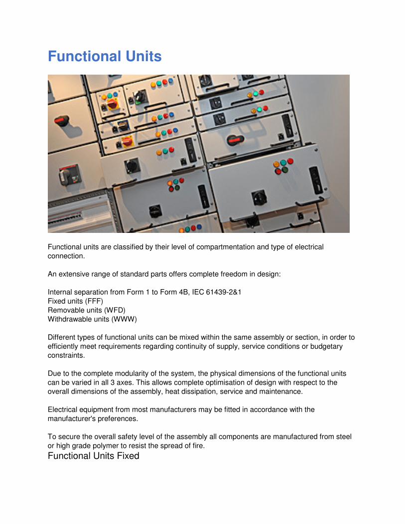
Functional Units
Functional units are classified by their level of compartmentation and type of electrical
connection.
An extensive range of standard parts offers complete freedom in design:
Internal separation from Form 1 to Form 4B, IEC 61439-2&1
Fixed units (FFF)
Removable units (WFD)
Withdrawable units (WWW)
Different types of functional units can be mixed within the same assembly or section, in order to
efficiently meet requirements regarding continuity of supply, service conditions or budgetary
constraints.
Due to the complete modularity of the system, the physical dimensions of the functional units
can be varied in all 3 axes. This allows complete optimisation of design with respect to the
overall dimensions of the assembly, heat dissipation, service and maintenance.
Electrical equipment from most manufacturers may be fitted in accordance with the
manufacturer's preferences.
To secure the overall safety level of the assembly all components are manufactured from steel
or high grade polymer to resist the spread of fire.
Functional Units Fixed
A fixed type panel is characterised as a panel mounted with components assembled and wired
on mounting plates, and connected to the main-circuit by cable or copper connections. The
panels can be designed with internal form of separation, Form 1-4 acc. to IEC 61439-2&1.
The panels can be designed with internal form of separation by steel compartmentation
according to IEC 61439-2&1, Form 1-4 and according to BS 61439-1&2.
In the case of fixed parts, the connections of main-circuits can only be established or broken
when the panel not live. In general, removal and installation of fixed parts requires the use of a
tool.
The connection or disconnection of a fixed part normally requires the disconnection of the
complete panel or part of it.
In order to prevent unauthorised operation, the switching device may be provided with means to
secure it in one or more of its positions.
- Adjustable depth mounting plates
- Non ferrous gland plates
- Metal or plastic cable box
- Sizes: 4 widths, 16 heights, 6 depths
Functional Units Draw-Out
All standard sections are equipped to fit - Removable units (RMU), Withdrawable units (WDU),
Mini withdrawable unit (MDU), Inline units (ILU)
All units fully interchangeable and upgradeable (except ILU's)
A removable type panel is characterised as a panel where a part may be removed entirely from
the panel and replaced even though the circuit to which it is connected may be live.
The removable parts shall be so designed that their electrical equipment can be safely
disconnected from or connected to the main-circuit whilst this circuit is live. Minimum clearances
and creepage distances as described in IEC 61439-2&1.
Removable parts shall have a connected position and a removed position.
A withdrawable type panel is characterised as a panel where the removable parts can be moved
to a position where an isolating distance is established, whilst remaining mechanically attached
to the panel. The isolation distance shall comply with IEC 61439-2&1 clause 7.1.2.2. The
withdrawable parts shall be so designed that their electrical equipment can be safely
disconnected or connected to the main-circuit whilst this circuit is live.
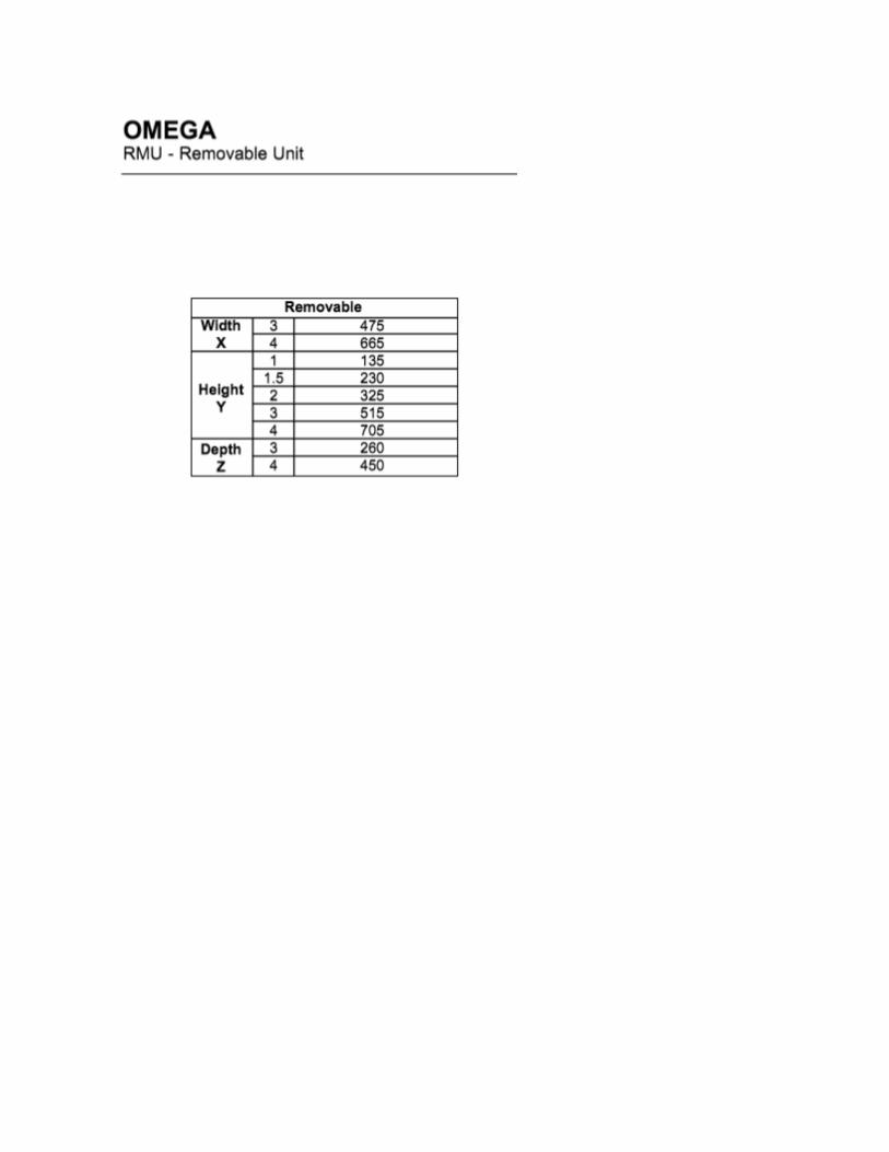
Removable Units Type
High protection against contact
Rating up to 630 A, 500 kW, 690 V
Fixed or hinged front panel
Coding system
Front or rear access
Unique safety locking mechanism
Fully re-configurable while live
Accommodates components from many manufacturers
DeviceNet & Profibus connection
Sizes: X = 3, 4 Y= 0.5, 1, 1.5, 2, 2.5, 3, 3.5, 4.
Up to 20 units per section
Withdrawable
High operational safety
Rating up to 630 A, 500 kW, 690 V
Auxiliary controls up to 46 control pins
Fully re-configurable while live
Coding system
Safe operation...IP20 protection in all positions
Front or rear access
Fixed or hinged front panel
Unique safety locking mechanism
Accommodates components from many manufacturers
DeviceNet & Profibus connection
Sizes: X = 3, 4 Y = 0.5, 1, 1.5, 2, 2.5, 3, 3.5, 4
Up to 20 units per section
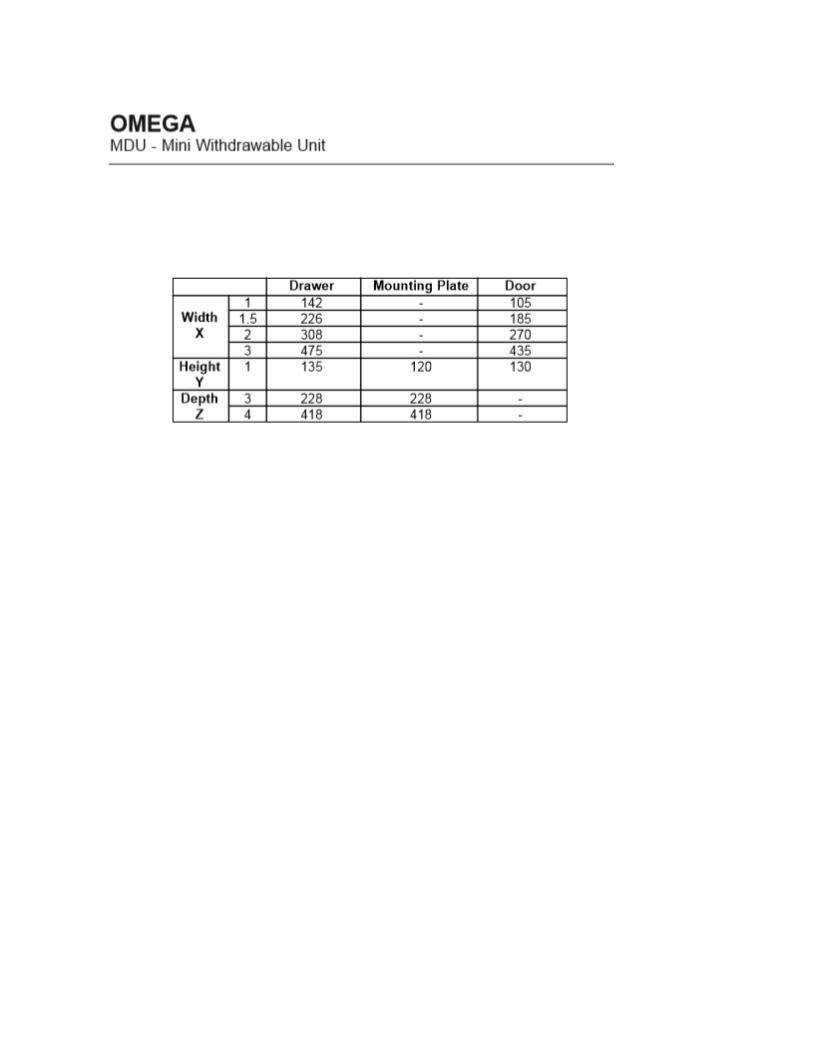
Mini-Withdrawable
High personal protection
Rating up to 80 A, 55 kW, 690 V
Auxiliary controls up to 46 control pins
Front or rear access
Removable interface box
Interface box can be prewired
Fully re-configurable while live
Unique safety locking mechanism
Accommodates components from many manufacturers
Coding system
DeviceNet & Profibus connection
Sizes: X = 1, 1.5, 2, 3 Y = 1
Up to 40 units per stack
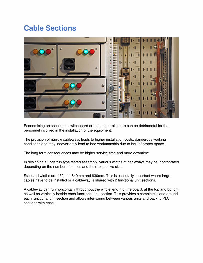
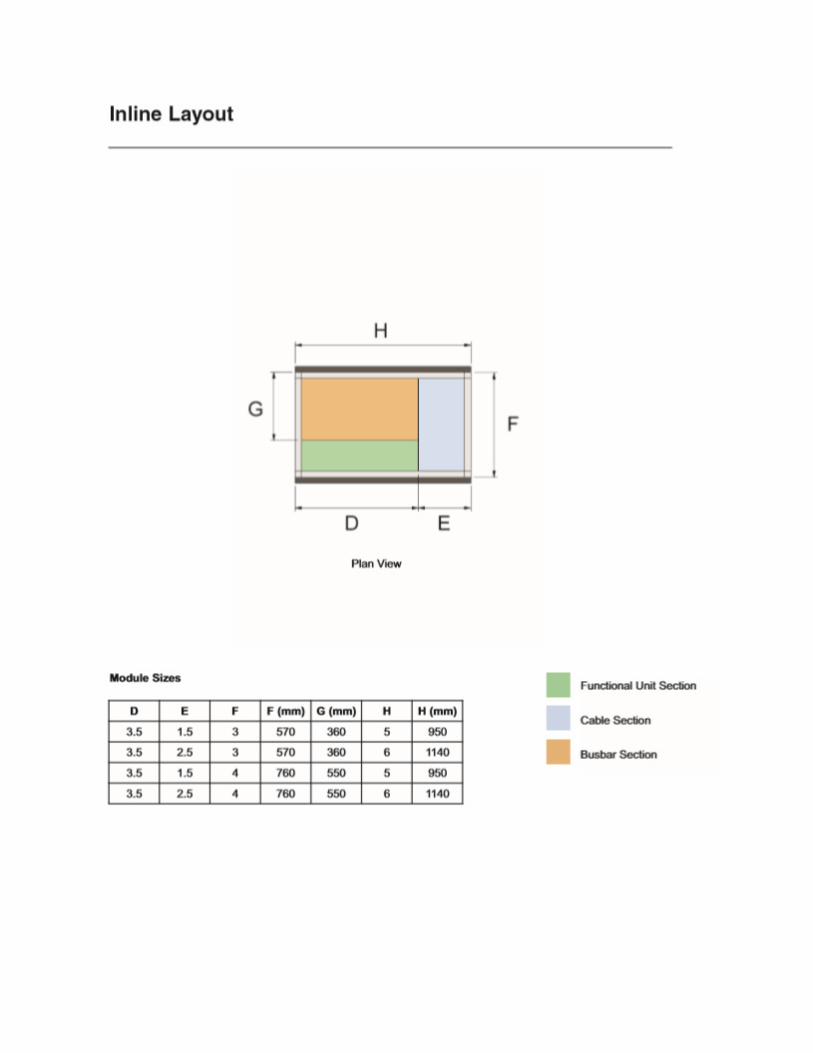
Cable Sections
Economising on space in a switchboard or motor control centre can be detrimental for the
personnel involved in the installation of the equipment.
The provision of narrow cableways leads to higher installation costs, dangerous working
conditions and may inadvertently lead to bad workmanship due to lack of proper space.
The long term consequences may be higher service time and more downtime.
In designing a Logstrup type tested assembly, various widths of cableways may be incorporated
depending on the number of cables and their respective size.
Standard widths are 450mm, 640mm and 830mm. This is especially important where large
cables have to be installed or a cableway is shared with 2 functional unit sections.
A cableway can run horizontally throughout the whole length of the board, at the top and bottom
as well as vertically beside each functional unit section. This provides a complete island around
each functional unit section and allows inter-wiring between various units and back to PLC
sections with ease.
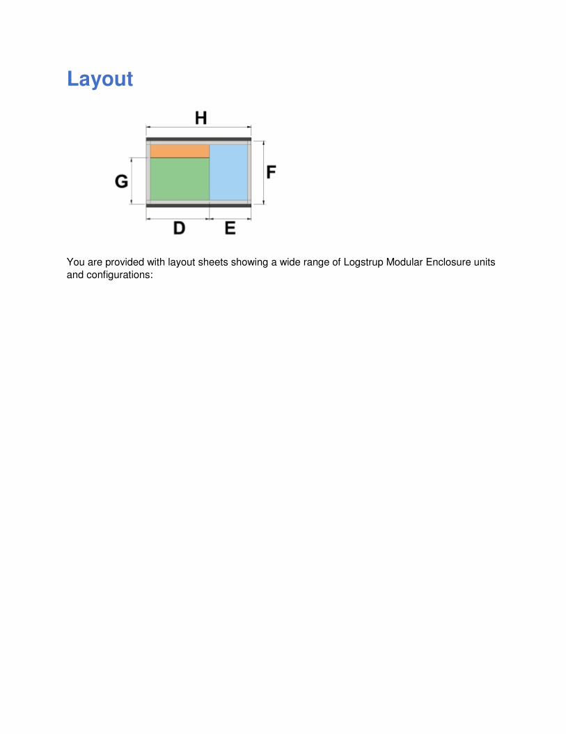
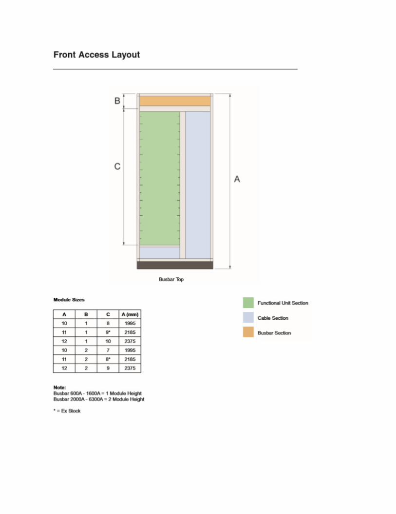
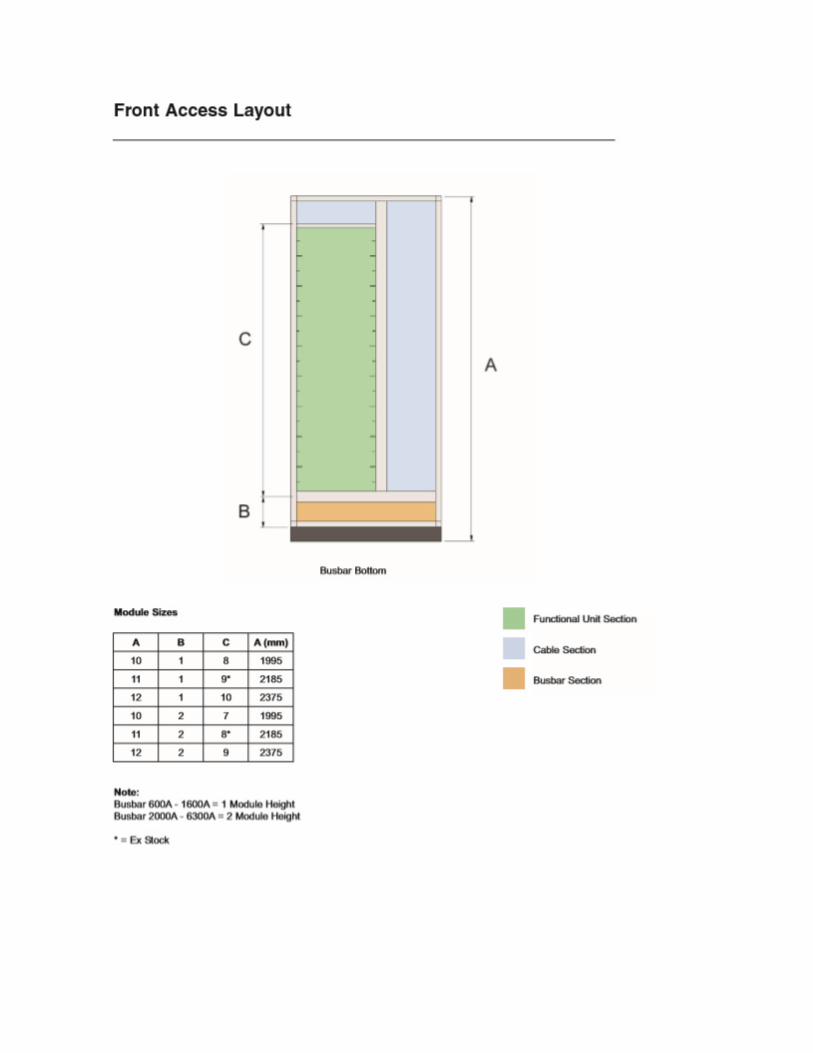
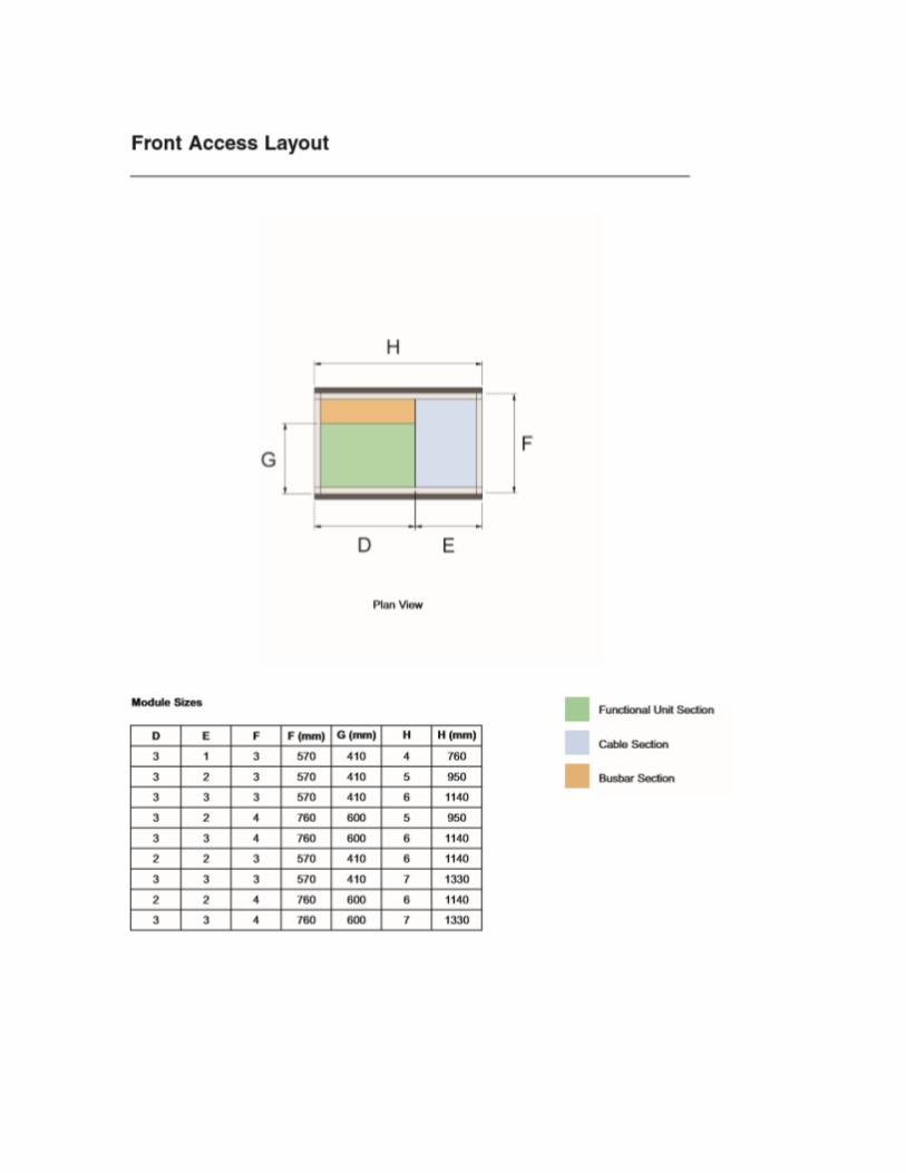
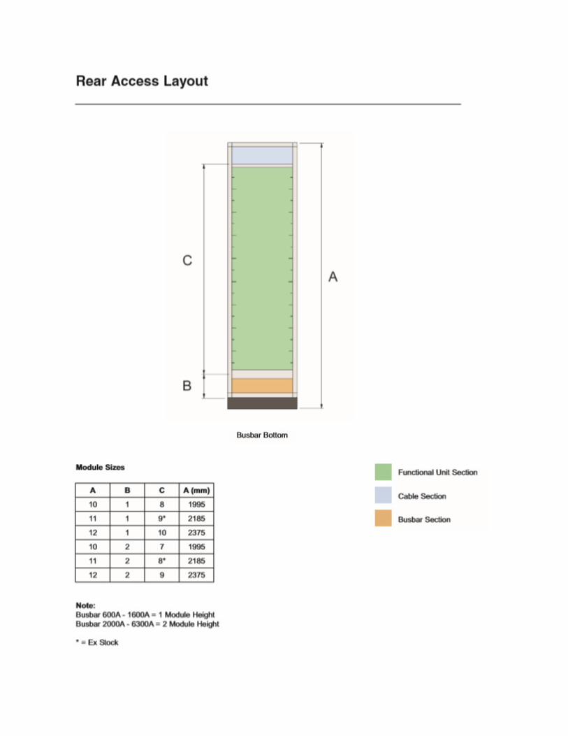
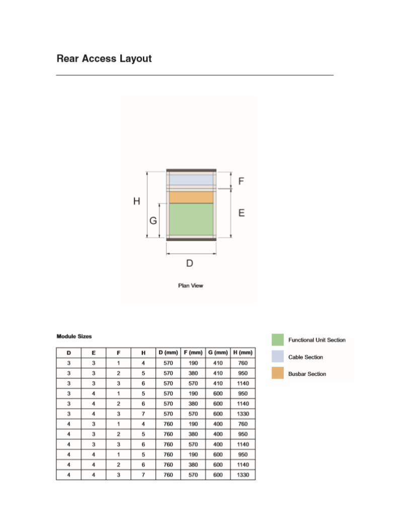
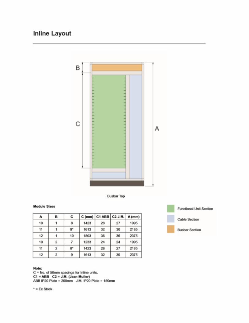
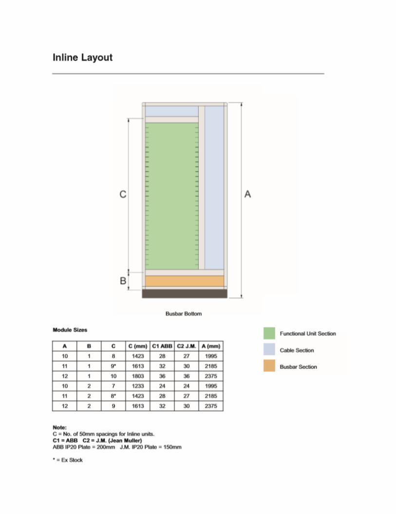
Layout
You are provided with layout sheets showing a wide range of Logstrup Modular Enclosure units
and configurations:
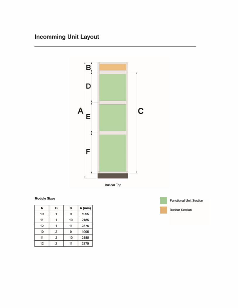
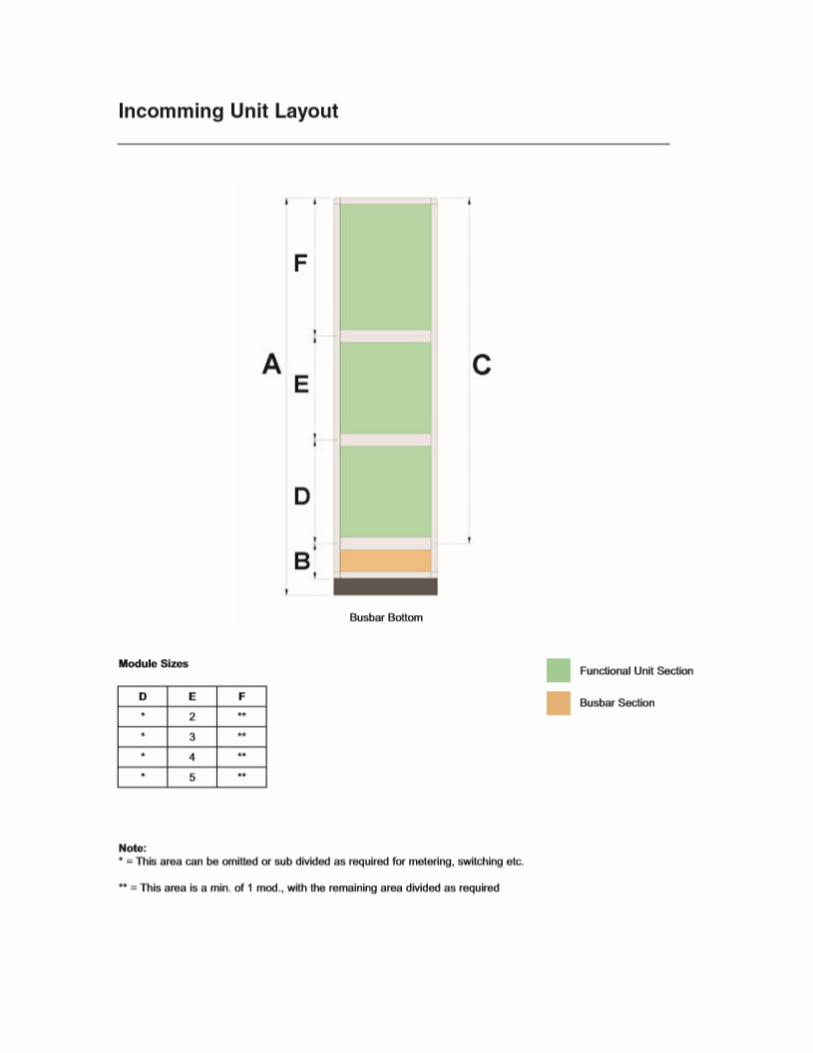
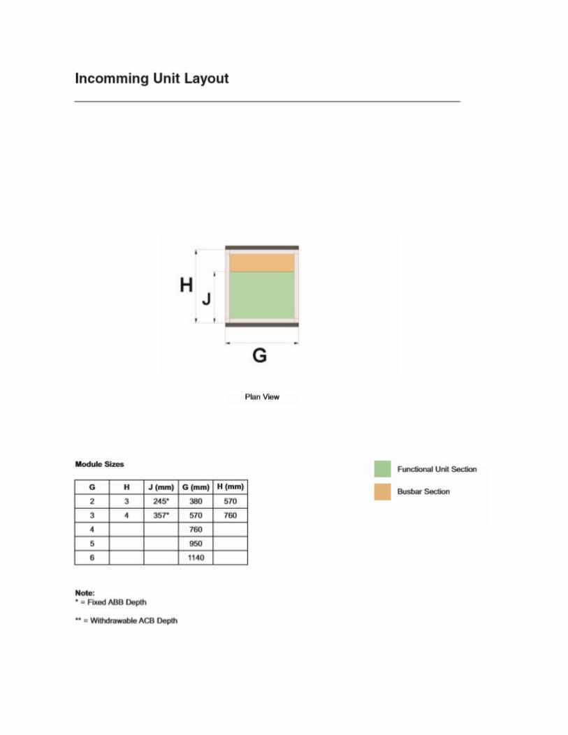
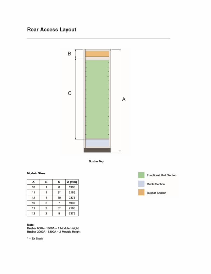
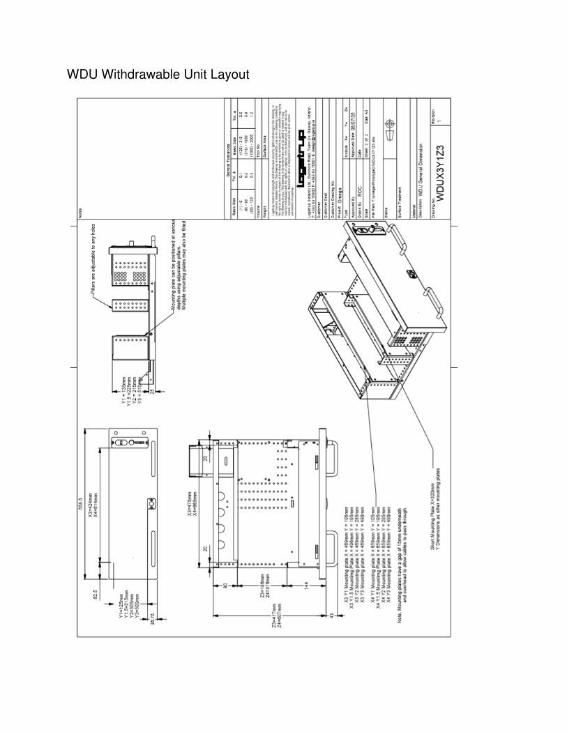
WDU Withdrawable Unit Layout

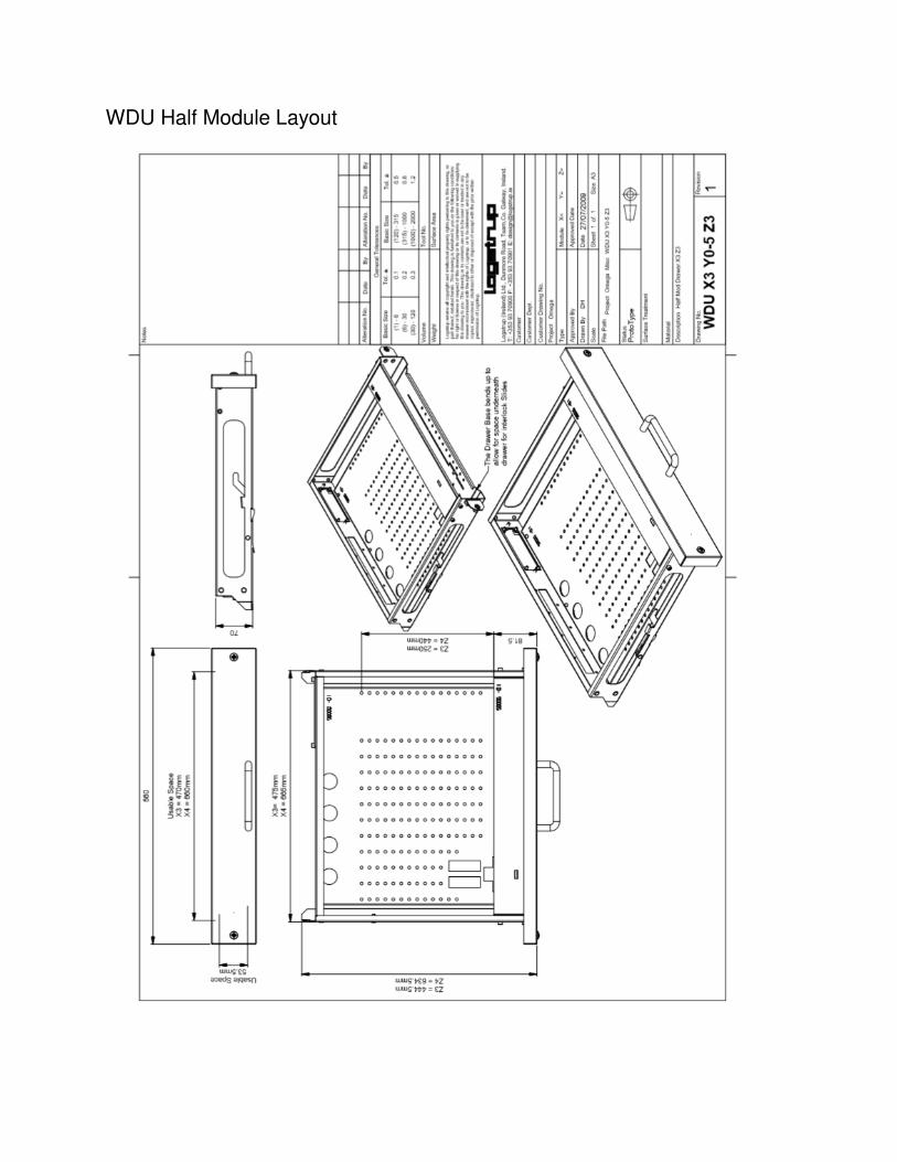
WDU Half Module Layout
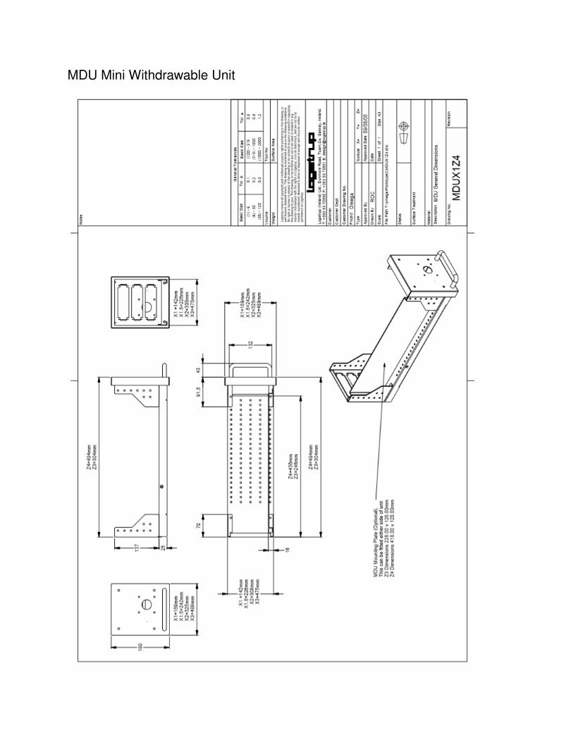
MDU Mini Withdrawable Unit
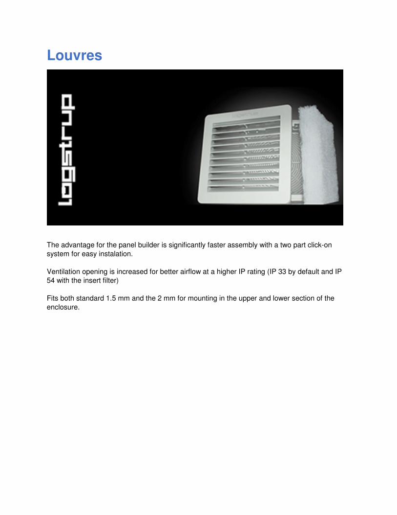
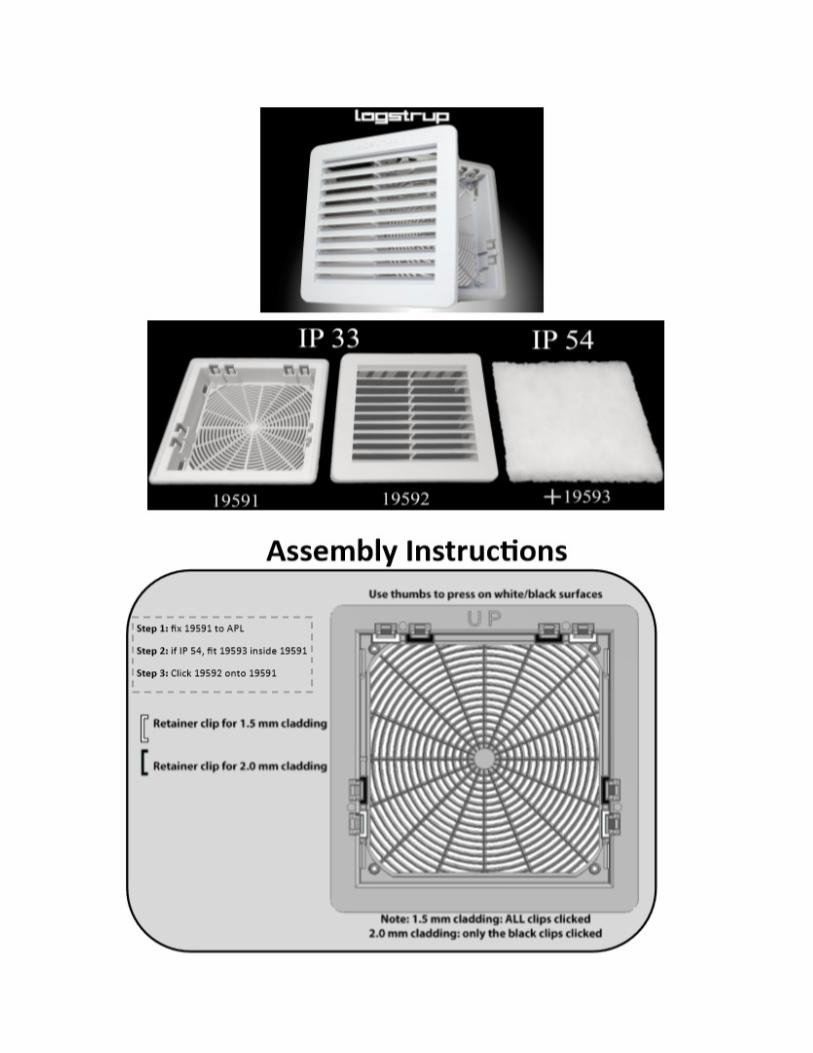
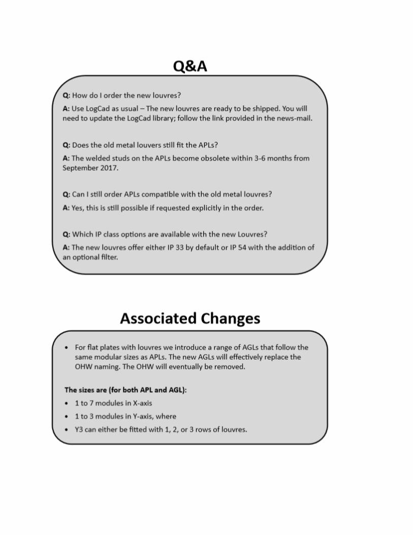
Louvres
The advantage for the panel builder is significantly faster assembly with a two part click-on
system for easy instalation.
Ventilation opening is increased for better airflow at a higher IP rating (IP 33 by default and IP
54 with the insert filter)
Fits both standard 1.5 mm and the 2 mm for mounting in the upper and lower section of the
enclosure.
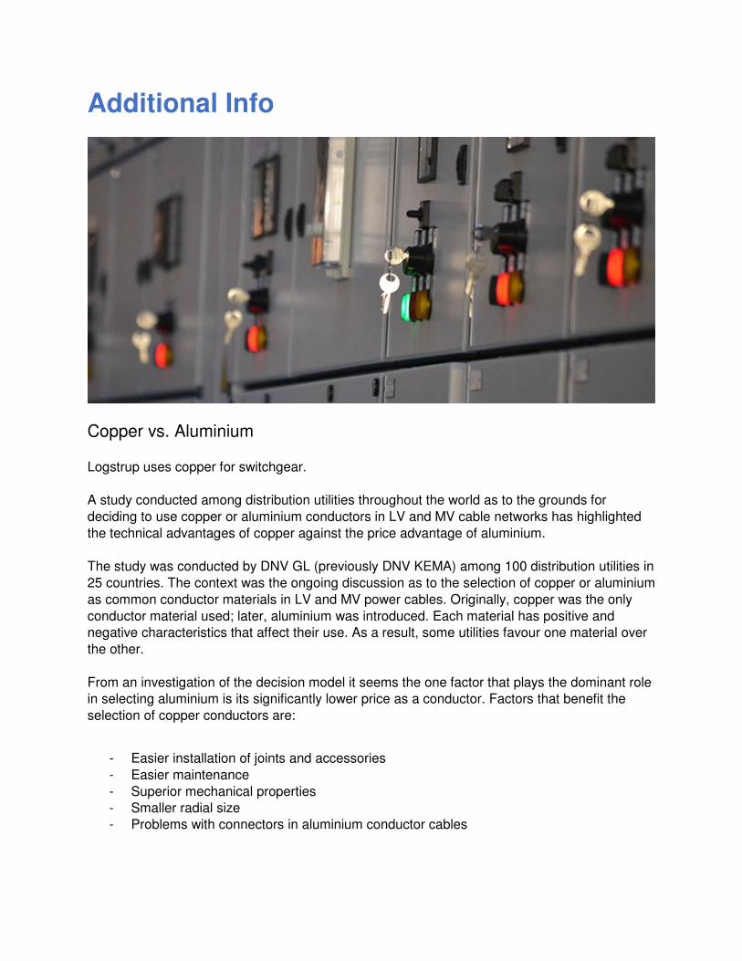
Additional Info
Copper vs. Aluminium
Logstrup uses copper for switchgear.
A study conducted among distribution utilities throughout the world as to the grounds for
deciding to use copper or aluminium conductors in LV and MV cable networks has highlighted
the technical advantages of copper against the price advantage of aluminium.
The study was conducted by DNV GL (previously DNV KEMA) among 100 distribution utilities in
25 countries. The context was the ongoing discussion as to the selection of copper or aluminium
as common conductor materials in LV and MV power cables. Originally, copper was the only
conductor material used; later, aluminium was introduced. Each material has positive and
negative characteristics that affect their use. As a result, some utilities favour one material over
the other.
From an investigation of the decision model it seems the one factor that plays the dominant role
in selecting aluminium is its significantly lower price as a conductor. Factors that benefit the
selection of copper conductors are:
- Easier installation of joints and accessories
- Easier maintenance
- Superior mechanical properties
- Smaller radial size
- Problems with connectors in aluminium conductor cables
The report also provides detailed background to the use of conductors in LV and MV power
cable networks, covering topics such as available conductors for LV and MV cables; typical
differences between copper and aluminium; and failure mechanisms related to conductors.
A number of failure mechanisms related to aluminium conductors were identified, which the
authors consider important as they should influence the decision model:
Chemical reaction between aluminium and water, resulting in the development of high pressure
hydrogen and related joint failures.
Chemical reaction between aluminium and oxygen, resulting in high transition resistances in
joints and connectors, and related joint failure.
Thermo-mechanical behaviour of aluminium due to a significantly higher coefficient of
expansion and related mechanical failure.
The authors of the report are Wim Boone and Christiaan Sonderen from global technical
advisory agency DNV GL.

Impact of welding
For environmental reasons, Logstrup switchboards are made without the use of welding. This
significantly reduces CO2 emissions, making Logstrup the greenest switchboard provider on the
market.