LOGO! - Siemensw5.siemens.com/.../logo/Documents/logo_manual_en.pdf · LOGO! software 7...
290
Preface, Contents Getting started with LOGO! 1 LOGO! installation and wiring 2 Programming LOGO! 3 LOGO! functions 4 Configuring LOGO! 5 LOGO! memory and battery cards 6 LOGO! software 7 Applications 8 Technical data A Determining the cycle time B LOGO! without display C LOGO! menu structure D Order numbers E Abbreviations F Index 07/2008 A5E01248535 -01 LOGO! Manual This manual has the order number: 6ED1050-1AA00-0BE7
-
Upload
truonghuong -
Category
Documents
-
view
222 -
download
2
Transcript of LOGO! - Siemensw5.siemens.com/.../logo/Documents/logo_manual_en.pdf · LOGO! software 7...

Preface, Contents
Getting started with LOGO!1
LOGO! installation and wiring2
Programming LOGO!3
LOGO! functions4
Configuring LOGO!5
LOGO! memory and battery cards6
LOGO! software7
Applications8
Technical data A
Determining the cycle time B
LOGO! without display C
LOGO! menu structure D
Order numbers E
Abbreviations F
Index
07/2008A5E01248535--01
LOGO!
Manual
This manual has the order number:6ED1050-1AA00-0BE7

!Danger
indicates that death or severe personal injury will result if proper precautions are not taken.
!Warning
indicates that death or severe personal injury may result if proper precautions are not taken.
!Caution
with a safety alert symbol indicates that minor personal injury can result if proper precautions are nottaken.
Caution
without a safety alert symbol indicates that property damage can result if proper precautions are nottaken.
Notice
indicates that an unintended result or situation can occur if the corresponding notice is not taken intoaccount.
If more than one degree of danger is present, the warning notice representing the highest degree ofdanger will be used. A notice warning of injury to persons with a safety alert symbol may also include awarning relating to property damage.
Qualified PersonnelThe device/system may only be set up and used in conjunction with this documentation. Commissioningand operation of a device/system may only be performed by qualified personnel. Within the context of thesafety notices in this documentation qualified persons are defined as persons who are authorized tocommission, ground and label devices, systems and circuits in accordance with established safetypractices and standards.
Prescribed UsageNote the following:
!WarningThis device and its components may only be used for the applications described in the catalog or thetechnical description, and only in connection with devices or components from other manufacturers whichhave been approved or recommended by Siemens.
Correct, reliable operation of the product requires proper transport, storage, positioning and assembly aswell as careful operation and maintenance.
TrademarksAll names identified by ® are registered trademarks of the Siemens AG.The remaining trademarks in this publication may be trademarks whose use by third parties for their ownpurposes could violate the rights of the owner.
Disclaim of LiabilityWe have reviewed the contents of this publication to ensure consistency with the hardware and softwaredescribed. Since variance cannot be precluded entirely, we cannot guarantee full consistency. However,the information in this publication is reviewed regularly and any necessary corrections are included insubsequent editions.
Safety GuidelinesThis manual contains notices you have to observe in order to ensure your personal safety, as well as toprevent damage to property. The notices referring to your personal safety are highlighted in the manual bya safety alert symbol, notices referring to property damage only have no safety alert symbol. The noticesshown below are graded according to the degree of danger.
Copyright E Siemens AG 2008Technical data subject to change
SIEMENS AGIndustry SectorPostfach 484890437 NÜRNBERGGERMANY
A5E01248535--0107/2008

3LOGO! ManualA5E01248535--01
PrefaceDear customer
We thank you for purchasing LOGO! and congratulate you on your decision. With LOGO! youhave acquired a logic module that meets the stringent quality requirements of ISO 9001.
LOGO! can be used in many fields of applications. Due to its high functionality and easyoperation, LOGO! offers you the utmost efficiency for almost any application.
Purpose of this manualThis LOGO! manual provides you with information about the creation of circuit programs, aboutthe installation and use of LOGO! 0BA6 basic modules, the LOGO! TD (Text Display) and theLOGO! expansion modules, and about their compatibility with the previous 0BA0-0BA5 versions(0BAx are the last four characters of the order number of the basic modules and differentiate thedevice series).
LOGO!’s place in information technologyThe wiring information in your LOGO! manual is also found in the LOGO! Product Info includedwith all devices. For further information on programming the LOGO! on your PC, refer to theOnline Help for LOGO!Soft Comfort.
LOGO!Soft Comfort is the programming software for PCs. It runs under WindowsR (includingWindows VistaR ), LinuxR, and Mac OS XR. It helps you to get started with LOGO! and to write,test, print out and archive your programs, independent of the LOGO!.
GuideThe manual is divided into 8 chapters:
• Getting started with LOGO!
• LOGO! installation and wiring
• Programming LOGO!
• LOGO! functions
• Configuring LOGO!
• LOGO! memory and battery cards
• LOGO! software
• ApplicationsThe manual also includes appendices A -- F, which follow the chapters.

Preface
4LOGO! Manual
A5E01248535--01
Valid range of this manualThe manual applies to devices of series 0BA6.
New features of the LOGO! 0BA6 device series
• The LOGO! TD (Text Display) provides an additional display device for messages, andcontains four cursor keys and four functions keys that can be used in the circuit program.
• The new LOGO! Battery Card and the LOGO! Combined Memory/Battery Card provideup to two years of backup time for the real-time clock. The new LOGO! Memory Cardand the Combined Memory/Battery Card provide 32 Kbytes memory space: four timesthe memory space of the LOGO! 0BA5 Memory Card.
• Additional optional analog inputs and fast digital inputs are available on some of theLOGO! 0BA6 basic modules.
• LOGO! 0BA6 menus can be displayed in nine supported languages. You have aconfiguration choice to specify the language for LOGO! menus.
• New instruction blocks are available: Pulse Width Modulator (PWM), Analog Math, andAnalog Math Error Detection.
• Message texts can tick on and off the display; can include bar graphs, can switchbetween two character sets, and can be displayed on either the LOGO! Display, theLOGO! TD, or both. Full editing capabilities are available from LOGO!Soft Comfort;editing from the LOGO! basic module is limited to simple text. See section 2.1.3 forfurther details.
• A modem interface between a PC and LOGO! 0BA6 Basic module is supported, and isconfigurable from LOGO!Soft Comfort. LOGO! 0BA6 supports the following modems:
-- INSYS Modem 336 4 1-- INSYS Modem 56K small INT 2.0
LOGO! 0BA6 supports other modems under the condition that RS232 interface pin 1provides 5 mA current to the PC cable.
• USB PC cable between a PC and LOGO! basic module is provided.
• This series supports 0/4-20 mA for the AM2 AQ analog outputs. Note that the LOGO!AM2 AQ module that supports 0/4-20 mA outputs will be released some time later thanLOGO! 0BA6 basic module.
• You can now have up to 200 program blocks in your circuit program.
Additional differences compared to previous devices (0BA0 to 0BA5)
• Extended set of reference parameters for function blocks.
• Enhancements to up/down counter, hours counter, yearly timer and analog watchdoginstruction blocks.
• You can find information on compatibility of LOGO! 0BA6 to previous devices at section2.1.3.
Additional support
http://www.siemens.com/logo
Phone: +49 (0)180 5050-222Fax: +49 (0)180 5050-223E-Mail: [email protected]

Contents
5LOGO! ManualA5E01248535--01
Contents
1 Getting started with LOGO! 9. . . . . . . . . . . . . . . . . . . . . . . . . . . . . . . . . . . . . . . . . . . . .
2 LOGO! installation and wiring 23. . . . . . . . . . . . . . . . . . . . . . . . . . . . . . . . . . . . . . . . . . .
2.1 Modular LOGO! setup 25. . . . . . . . . . . . . . . . . . . . . . . . . . . . . . . . . . . . . . . . . . .2.1.1 Maximum setup 25. . . . . . . . . . . . . . . . . . . . . . . . . . . . . . . . . . . . . . . . . . . . . . . . .2.1.2 Setup with different voltage classes 27. . . . . . . . . . . . . . . . . . . . . . . . . . . . . . . .2.1.3 Compatibility 28. . . . . . . . . . . . . . . . . . . . . . . . . . . . . . . . . . . . . . . . . . . . . . . . . . . .
2.2 Installing/removing LOGO! 29. . . . . . . . . . . . . . . . . . . . . . . . . . . . . . . . . . . . . . .2.2.1 DIN rail mounting 30. . . . . . . . . . . . . . . . . . . . . . . . . . . . . . . . . . . . . . . . . . . . . . . .2.2.2 Wall-mounting 33. . . . . . . . . . . . . . . . . . . . . . . . . . . . . . . . . . . . . . . . . . . . . . . . . .2.2.3 Mounting the LOGO! TD 34. . . . . . . . . . . . . . . . . . . . . . . . . . . . . . . . . . . . . . . . .2.2.4 Labeling LOGO! 35. . . . . . . . . . . . . . . . . . . . . . . . . . . . . . . . . . . . . . . . . . . . . . . . .
2.3 Wiring LOGO! 35. . . . . . . . . . . . . . . . . . . . . . . . . . . . . . . . . . . . . . . . . . . . . . . . . .2.3.1 Connecting the power supply 35. . . . . . . . . . . . . . . . . . . . . . . . . . . . . . . . . . . . .2.3.2 Connecting the LOGO! TD power supply 37. . . . . . . . . . . . . . . . . . . . . . . . . . .2.3.3 Connecting LOGO! inputs 38. . . . . . . . . . . . . . . . . . . . . . . . . . . . . . . . . . . . . . . .2.3.4 Connecting outputs 44. . . . . . . . . . . . . . . . . . . . . . . . . . . . . . . . . . . . . . . . . . . . . .2.3.5 Connecting the EIB bus 46. . . . . . . . . . . . . . . . . . . . . . . . . . . . . . . . . . . . . . . . . .2.3.6 Connecting the AS interface bus 47. . . . . . . . . . . . . . . . . . . . . . . . . . . . . . . . . .
2.4 Putting into operation 49. . . . . . . . . . . . . . . . . . . . . . . . . . . . . . . . . . . . . . . . . . . .2.4.1 Switching on the LOGO!/Power On 49. . . . . . . . . . . . . . . . . . . . . . . . . . . . . . . .2.4.2 Putting a CM EIB/KNX into operation 51. . . . . . . . . . . . . . . . . . . . . . . . . . . . . .2.4.3 Operating states 52. . . . . . . . . . . . . . . . . . . . . . . . . . . . . . . . . . . . . . . . . . . . . . . .
3 Programming LOGO! 55. . . . . . . . . . . . . . . . . . . . . . . . . . . . . . . . . . . . . . . . . . . . . . . . . . .
3.1 Connectors 56. . . . . . . . . . . . . . . . . . . . . . . . . . . . . . . . . . . . . . . . . . . . . . . . . . . . .
3.2 EIB inputs/outputs 58. . . . . . . . . . . . . . . . . . . . . . . . . . . . . . . . . . . . . . . . . . . . . . .
3.3 Blocks and block numbers 59. . . . . . . . . . . . . . . . . . . . . . . . . . . . . . . . . . . . . . . .
3.4 From circuit diagram to LOGO! program 62. . . . . . . . . . . . . . . . . . . . . . . . . . . .
3.5 The four golden rules for operating LOGO! 64. . . . . . . . . . . . . . . . . . . . . . . . . .
3.6 Overview of LOGO! menus 66. . . . . . . . . . . . . . . . . . . . . . . . . . . . . . . . . . . . . . .
3.7 Writing and starting the circuit program 67. . . . . . . . . . . . . . . . . . . . . . . . . . . . .3.7.1 Selecting programming mode 67. . . . . . . . . . . . . . . . . . . . . . . . . . . . . . . . . . . . .3.7.2 The first circuit program 68. . . . . . . . . . . . . . . . . . . . . . . . . . . . . . . . . . . . . . . . . .3.7.3 Circuit program input 70. . . . . . . . . . . . . . . . . . . . . . . . . . . . . . . . . . . . . . . . . . . . .3.7.4 Assigning a circuit program name 75. . . . . . . . . . . . . . . . . . . . . . . . . . . . . . . . .3.7.5 Password 76. . . . . . . . . . . . . . . . . . . . . . . . . . . . . . . . . . . . . . . . . . . . . . . . . . . . . .3.7.6 Switching LOGO! to RUN mode 79. . . . . . . . . . . . . . . . . . . . . . . . . . . . . . . . . . .3.7.7 Second circuit program 81. . . . . . . . . . . . . . . . . . . . . . . . . . . . . . . . . . . . . . . . . . .3.7.8 Deleting a block 86. . . . . . . . . . . . . . . . . . . . . . . . . . . . . . . . . . . . . . . . . . . . . . . . .3.7.9 Deleting block groups 87. . . . . . . . . . . . . . . . . . . . . . . . . . . . . . . . . . . . . . . . . . . .3.7.10 Correcting programming errors 88. . . . . . . . . . . . . . . . . . . . . . . . . . . . . . . . . . . .3.7.11 Selecting analog output values for RUN/STOP transition 88. . . . . . . . . . . . . .3.7.12 Defining the type of analog outputs 89. . . . . . . . . . . . . . . . . . . . . . . . . . . . . . . .3.7.13 Deleting the circuit program and password 90. . . . . . . . . . . . . . . . . . . . . . . . . .3.7.14 Summertime/wintertime conversion 91. . . . . . . . . . . . . . . . . . . . . . . . . . . . . . . .3.7.15 Synchronization 95. . . . . . . . . . . . . . . . . . . . . . . . . . . . . . . . . . . . . . . . . . . . . . . . .
3.8 Memory space and circuit program size 96. . . . . . . . . . . . . . . . . . . . . . . . . . . .

Contents
6LOGO! Manual
A5E01248535--01
4 LOGO! functions 101. . . . . . . . . . . . . . . . . . . . . . . . . . . . . . . . . . . . . . . . . . . . . . . . . . . . . . .
4.1 Constants and connectors -- Co 102. . . . . . . . . . . . . . . . . . . . . . . . . . . . . . . . . . .
4.2 Basic functions list -- GF 105. . . . . . . . . . . . . . . . . . . . . . . . . . . . . . . . . . . . . . . . . .4.2.1 AND 106. . . . . . . . . . . . . . . . . . . . . . . . . . . . . . . . . . . . . . . . . . . . . . . . . . . . . . . . . . .4.2.2 AND with edge evaluation 106. . . . . . . . . . . . . . . . . . . . . . . . . . . . . . . . . . . . . . . .4.2.3 NAND (not AND) 107. . . . . . . . . . . . . . . . . . . . . . . . . . . . . . . . . . . . . . . . . . . . . . .4.2.4 NAND with edge evaluation 108. . . . . . . . . . . . . . . . . . . . . . . . . . . . . . . . . . . . . . .4.2.5 OR 109. . . . . . . . . . . . . . . . . . . . . . . . . . . . . . . . . . . . . . . . . . . . . . . . . . . . . . . . . . . .4.2.6 NOR (not OR) 109. . . . . . . . . . . . . . . . . . . . . . . . . . . . . . . . . . . . . . . . . . . . . . . . . .4.2.7 XOR (exclusive OR) 110. . . . . . . . . . . . . . . . . . . . . . . . . . . . . . . . . . . . . . . . . . . . .4.2.8 NOT (Negation, Inverter) 111. . . . . . . . . . . . . . . . . . . . . . . . . . . . . . . . . . . . . . . . .
4.3 Special functions 111. . . . . . . . . . . . . . . . . . . . . . . . . . . . . . . . . . . . . . . . . . . . . . . .4.3.1 Designation of the inputs 112. . . . . . . . . . . . . . . . . . . . . . . . . . . . . . . . . . . . . . . . .4.3.2 Time response 113. . . . . . . . . . . . . . . . . . . . . . . . . . . . . . . . . . . . . . . . . . . . . . . . . .4.3.3 Backup of the real-time clock 114. . . . . . . . . . . . . . . . . . . . . . . . . . . . . . . . . . . . .4.3.4 Retentivity 114. . . . . . . . . . . . . . . . . . . . . . . . . . . . . . . . . . . . . . . . . . . . . . . . . . . . . .4.3.5 Parameter protection 114. . . . . . . . . . . . . . . . . . . . . . . . . . . . . . . . . . . . . . . . . . . .4.3.6 Calculating the gain and offset of analog values 115. . . . . . . . . . . . . . . . . . . . .
4.4 Special functions list -- SF 117. . . . . . . . . . . . . . . . . . . . . . . . . . . . . . . . . . . . . . . .4.4.1 On-delay 120. . . . . . . . . . . . . . . . . . . . . . . . . . . . . . . . . . . . . . . . . . . . . . . . . . . . . . .4.4.2 Off-delay 123. . . . . . . . . . . . . . . . . . . . . . . . . . . . . . . . . . . . . . . . . . . . . . . . . . . . . . .4.4.3 On-/Off-delay 124. . . . . . . . . . . . . . . . . . . . . . . . . . . . . . . . . . . . . . . . . . . . . . . . . . .4.4.4 Retentive on-delay 126. . . . . . . . . . . . . . . . . . . . . . . . . . . . . . . . . . . . . . . . . . . . . .4.4.5 Wiping relay (pulse output) 127. . . . . . . . . . . . . . . . . . . . . . . . . . . . . . . . . . . . . . .4.4.6 Edge triggered wiping relay 128. . . . . . . . . . . . . . . . . . . . . . . . . . . . . . . . . . . . . . .4.4.7 Asynchronous pulse generator 130. . . . . . . . . . . . . . . . . . . . . . . . . . . . . . . . . . . .4.4.8 Random generator 132. . . . . . . . . . . . . . . . . . . . . . . . . . . . . . . . . . . . . . . . . . . . . .4.4.9 Stairway lighting switch 134. . . . . . . . . . . . . . . . . . . . . . . . . . . . . . . . . . . . . . . . . .4.4.10 Multiple function switch 136. . . . . . . . . . . . . . . . . . . . . . . . . . . . . . . . . . . . . . . . . . .4.4.11 Weekly timer 139. . . . . . . . . . . . . . . . . . . . . . . . . . . . . . . . . . . . . . . . . . . . . . . . . . .4.4.12 Yearly timer 143. . . . . . . . . . . . . . . . . . . . . . . . . . . . . . . . . . . . . . . . . . . . . . . . . . . . .4.4.13 Up/down counter 149. . . . . . . . . . . . . . . . . . . . . . . . . . . . . . . . . . . . . . . . . . . . . . . .4.4.14 Hours counter 152. . . . . . . . . . . . . . . . . . . . . . . . . . . . . . . . . . . . . . . . . . . . . . . . . .4.4.15 Threshold trigger 156. . . . . . . . . . . . . . . . . . . . . . . . . . . . . . . . . . . . . . . . . . . . . . . .4.4.16 Analog threshold trigger 159. . . . . . . . . . . . . . . . . . . . . . . . . . . . . . . . . . . . . . . . . .4.4.17 Analog differential trigger 162. . . . . . . . . . . . . . . . . . . . . . . . . . . . . . . . . . . . . . . . .4.4.18 Analog comparator 165. . . . . . . . . . . . . . . . . . . . . . . . . . . . . . . . . . . . . . . . . . . . . .4.4.19 Analog watchdog 170. . . . . . . . . . . . . . . . . . . . . . . . . . . . . . . . . . . . . . . . . . . . . . . .4.4.20 Analog amplifier 173. . . . . . . . . . . . . . . . . . . . . . . . . . . . . . . . . . . . . . . . . . . . . . . . .4.4.21 Latching relay 174. . . . . . . . . . . . . . . . . . . . . . . . . . . . . . . . . . . . . . . . . . . . . . . . . . .4.4.22 Pulse relay 175. . . . . . . . . . . . . . . . . . . . . . . . . . . . . . . . . . . . . . . . . . . . . . . . . . . . .4.4.23 Message texts 177. . . . . . . . . . . . . . . . . . . . . . . . . . . . . . . . . . . . . . . . . . . . . . . . . .4.4.24 Softkey 189. . . . . . . . . . . . . . . . . . . . . . . . . . . . . . . . . . . . . . . . . . . . . . . . . . . . . . . .4.4.25 Shift register 192. . . . . . . . . . . . . . . . . . . . . . . . . . . . . . . . . . . . . . . . . . . . . . . . . . . .4.4.26 Analog Multiplexer 194. . . . . . . . . . . . . . . . . . . . . . . . . . . . . . . . . . . . . . . . . . . . . . .4.4.27 Analog Ramp 196. . . . . . . . . . . . . . . . . . . . . . . . . . . . . . . . . . . . . . . . . . . . . . . . . . .4.4.28 PI controller 200. . . . . . . . . . . . . . . . . . . . . . . . . . . . . . . . . . . . . . . . . . . . . . . . . . . .4.4.29 Pulse Width Modulator (PWM) 206. . . . . . . . . . . . . . . . . . . . . . . . . . . . . . . . . . . .4.4.30 Analog math 209. . . . . . . . . . . . . . . . . . . . . . . . . . . . . . . . . . . . . . . . . . . . . . . . . . . .4.4.31 Analog math error detection 212. . . . . . . . . . . . . . . . . . . . . . . . . . . . . . . . . . . . . .
5 Configuring LOGO! 215. . . . . . . . . . . . . . . . . . . . . . . . . . . . . . . . . . . . . . . . . . . . . . . . . . . . .
5.1 Selecting parameter assignment mode 216. . . . . . . . . . . . . . . . . . . . . . . . . . . . .
Contents
7LOGO! ManualA5E01248535--01
5.1.1 Parameters 217. . . . . . . . . . . . . . . . . . . . . . . . . . . . . . . . . . . . . . . . . . . . . . . . . . . . .5.1.2 Selecting the parameters 218. . . . . . . . . . . . . . . . . . . . . . . . . . . . . . . . . . . . . . . . .5.1.3 Modifying parameters 219. . . . . . . . . . . . . . . . . . . . . . . . . . . . . . . . . . . . . . . . . . . .
5.2 Setting the default values for LOGO! 221. . . . . . . . . . . . . . . . . . . . . . . . . . . . . . .5.2.1 Setting the time of day and date (LOGO! ... C) 222. . . . . . . . . . . . . . . . . . . . . .5.2.2 Setting the display contrast and backlight choice 223. . . . . . . . . . . . . . . . . . . . .5.2.3 Setting the menu language 224. . . . . . . . . . . . . . . . . . . . . . . . . . . . . . . . . . . . . . .5.2.4 Setting the number of AIs in the Basic Module 225. . . . . . . . . . . . . . . . . . . . . . .5.2.5 Setting the start screen 226. . . . . . . . . . . . . . . . . . . . . . . . . . . . . . . . . . . . . . . . . .
6 LOGO! memory and battery cards 227. . . . . . . . . . . . . . . . . . . . . . . . . . . . . . . . . . . . . . .
6.1 Security function (CopyProtect) 230. . . . . . . . . . . . . . . . . . . . . . . . . . . . . . . . . . .
6.2 Inserting and removing memory and battery cards 232. . . . . . . . . . . . . . . . . . .
6.3 Copying data from LOGO! to the memory card 234. . . . . . . . . . . . . . . . . . . . . .
6.4 Copying data from the memory card to LOGO! 235. . . . . . . . . . . . . . . . . . . . . .
7 LOGO! software 237. . . . . . . . . . . . . . . . . . . . . . . . . . . . . . . . . . . . . . . . . . . . . . . . . . . . . . . .
7.1 Connecting LOGO! to a PC 239. . . . . . . . . . . . . . . . . . . . . . . . . . . . . . . . . . . . . . .
8 Applications 241. . . . . . . . . . . . . . . . . . . . . . . . . . . . . . . . . . . . . . . . . . . . . . . . . . . . . . . . . . .
A Technical data 245. . . . . . . . . . . . . . . . . . . . . . . . . . . . . . . . . . . . . . . . . . . . . . . . . . . . . . . . . .
A.1 General technical data 245. . . . . . . . . . . . . . . . . . . . . . . . . . . . . . . . . . . . . . . . . . .
A.2 Technical data: LOGO! 230... 247. . . . . . . . . . . . . . . . . . . . . . . . . . . . . . . . . . . . .
A.3 Technical data: LOGO! DM8 230R and LOGO! DM16 230R 249. . . . . . . . . . .
A.4 Technical data: LOGO! 24... 251. . . . . . . . . . . . . . . . . . . . . . . . . . . . . . . . . . . . . .
A.5 Technical data: LOGO! DM8 24 and LOGO! DM16 24 253. . . . . . . . . . . . . . . .
A.6 Technical data: LOGO! 24RC... 255. . . . . . . . . . . . . . . . . . . . . . . . . . . . . . . . . . .
A.7 Technical data: LOGO! DM8 24 R and LOGO! DM16 24 R 257. . . . . . . . . . . .
A.8 Technical data: LOGO! 12/24... and LOGO! DM8 12/24R 259. . . . . . . . . . . . .
A.9 Switching capacity and service life of the relay outputs 261. . . . . . . . . . . . . . .
A.10 Technical data: LOGO! AM 2 262. . . . . . . . . . . . . . . . . . . . . . . . . . . . . . . . . . . . . .
A.11 Technical data: LOGO! AM 2 PT100 263. . . . . . . . . . . . . . . . . . . . . . . . . . . . . . .
A.12 Technical data: LOGO! AM 2 AQ 264. . . . . . . . . . . . . . . . . . . . . . . . . . . . . . . . . .
A.13 Technical data: CM EIB/KNX 265. . . . . . . . . . . . . . . . . . . . . . . . . . . . . . . . . . . . . .
A.14 Technical data: CM AS Interface 266. . . . . . . . . . . . . . . . . . . . . . . . . . . . . . . . . .
A.15 Technical data: LOGO!Power 12 V 267. . . . . . . . . . . . . . . . . . . . . . . . . . . . . . . .
A.16 Technical data: LOGO!Power 24 V 268. . . . . . . . . . . . . . . . . . . . . . . . . . . . . . . .
A.17 Technical data: LOGO! Contact 24/230 269. . . . . . . . . . . . . . . . . . . . . . . . . . . . .
A.18 Technical data: LOGO! TD (Text Display) 270. . . . . . . . . . . . . . . . . . . . . . . . . . .
A.19 Technical data: LOGO! Battery Card 270. . . . . . . . . . . . . . . . . . . . . . . . . . . . . . .

Contents
8LOGO! Manual
A5E01248535--01
B Determining the cycle time 271. . . . . . . . . . . . . . . . . . . . . . . . . . . . . . . . . . . . . . . . . . . . . .
C LOGO! without display 275. . . . . . . . . . . . . . . . . . . . . . . . . . . . . . . . . . . . . . . . . . . . . . . . . .
D LOGO! menu structure 277. . . . . . . . . . . . . . . . . . . . . . . . . . . . . . . . . . . . . . . . . . . . . . . . . .
D.1 LOGO! Basic Module 277. . . . . . . . . . . . . . . . . . . . . . . . . . . . . . . . . . . . . . . . . . . .
D.2 LOGO! TD 279. . . . . . . . . . . . . . . . . . . . . . . . . . . . . . . . . . . . . . . . . . . . . . . . . . . . .
E Order numbers 281. . . . . . . . . . . . . . . . . . . . . . . . . . . . . . . . . . . . . . . . . . . . . . . . . . . . . . . . .
F Abbreviations 283. . . . . . . . . . . . . . . . . . . . . . . . . . . . . . . . . . . . . . . . . . . . . . . . . . . . . . . . . .
Index 285. . . . . . . . . . . . . . . . . . . . . . . . . . . . . . . . . . . . . . . . . . . . . . . . . . . . . . . . . . . . . . . . . .

9LOGO! ManualA5E01248535--01
Getting started with LOGO!
Here’s LOGO!
LOGO! is a universal logic module made by Siemens that integrates:
• Controls
• Operator and display panel with background lighting
• Power supply
• Interface for expansion modules
• Interface for the memory card, battery card, combined memory/battery card or aPC cable
• Interface for an optional text display (TD) module
• Pre-configured standard functions, for example, on- and off-delays, pulse relayand softkey
• Timers
• Digital and analog flags
• Inputs and outputs, according to the device type
What LOGO! can do for you
LOGO! offers solutions for domestic and installation engineering applications suchas stairway lighting, external lighting, sun blinds, shutters, shop window lightingand more; switch cabinet engineering, as well as for mechanical and apparatusengineering such as gate control systems, air-conditioning systems, rand ainwaterpumps.
LOGO! can also be implemented for special control systems in conservatories orgreenhouses, for control signal processing and, by connecting a communicationmodule such as an AS--i module, for distributed local controlling of machines andprocesses.
Special versions without operator panel and display unit are available for seriesproduction applications in small machine, apparatus, switching cabinet andinstallation engineering.
1

Getting started with LOGO!
10LOGO! Manual
A5E01248535--01
Which devices are available?
LOGO! Basic is available in two voltage classes:
• Class 1 ± 24 V, i.e. 12 V DC, 24 V DC, 24 V AC
• Class 2 > 24 V, i.e. 115...240 V AC/DC
LOGO! Basic is available in two versions:
• With display: 8 inputs and 4 outputs
• Without display (”LOGO! Pure”): 8 inputs and 4 outputs
Each version is integrated into four subunits, is equipped with an expansioninterface and LOGO! TD interface and provides 39 pre-configured standard andspecial function blocks for the creation of your circuit program.
Which expansion modules are available?
• LOGO! digital modules DM8... are available for operation with 12 V DC, 24 VAC/DC and 115...240 V AC/DC, and are equipped with four inputs and fouroutputs.
• LOGO! digital modules DM16... are available for operation with 24 V DC and115...240 V AC/DC, and are equipped with eight inputs and eight outputs.
• LOGO! analog modules are available for operation with 24 V DC and some with12 V DC, depending on the specific module. Each is equipped with two analoginputs, two Pt100 inputs or two analog outputs.
The digital/analog modules are integrated in two or four subunits. Each one isequipped with two expansion interfaces for connecting additional modules.
Which display modules are available?
• LOGO! Basic with display
• LOGO! TD
Features of the LOGO! TD
The LOGO! TD is available with the 0BA6 series. It provides an additional displaythat is wider than the Basic module. It has four function keys that you can programin your circuit program as inputs. Like the LOGO! Basic module, it has four cursorkeys, an ESC and OK key that you can also program in your circuit program anduse for navigation on the LOGO! TD.
You can create and download a power--up screen for the LOGO! TD fromLOGO!Soft Comfort. This screen displays briefly when you initially power on theLOGO! TD. You can also upload the power--up screen from the LOGO! TD toLOGO!Soft Comfort.
The menus for the LOGO! TD are shown in Appendix section D.2. You configurethe settings for the LOGO! TD independently from the LOGO! Basic module. Thesettings can be different.

Getting started with LOGO!
11LOGO! ManualA5E01248535--01
Which communication modules are available?
• LOGO! communication module (CM) AS interface, which is described in moredetail in a separate documentation.
The communication module has four virtual inputs and outputs, and acts as aninterface between an AS-Interface system and a LOGO! system. The moduleenables four data bits to be transferred from the LOGO! Basic to theAS-Interface system and vice versa.
• LOGO! communication module (CM) EIB/KNX, which is described in more detailin a separate documentation.
CM EIB/KNX is a communication module (CM) for connecting the LOGO! to theEIB.
As an interface to EIB, CM EIB/KNX makes it possible to communicate withother EIB devices. To do this, you store a configuration in the CM EIB/KNX thatspecifies the inputs/outputs of the LOGO! to the EIB bus that are to be mapped.You can interconnect the corresponding inputs/outputs using LOGO! functions.

Getting started with LOGO!
12LOGO! Manual
A5E01248535--01
It’s your choice
The various LOGO! Basic versions, expansion modules, LOGO! TD andcommunication modules offer you a highly flexible and adaptive system to suit yourspecific tasks.
The LOGO! system offers you many solutions such as for small domesticinstallations, simple automation tasks, and even complex engineering tasksinvolving its integration into a bus system (e.g. communication module ASinterface).
Note
LOGO! Basic may only be equipped with expansion modules of the same voltageclass. Mechanical encoding pins in the housing prevent you from connectingdevices of a different voltage class.
Exception: The left-hand interface of an analog module or communication moduleis galvanically isolated.
This type of expansion module can therefore be connected to devices of a differentvoltage class. See also Chapter 2.1.
A LOGO! TD, if used, can be connected only to a LOGO! 0BA6 Basic module.
Each LOGO! Basic supports the following connections for the creation of the circuitprogram, regardless of the number of connected modules:
• Digital inputs 11 to I24
• Analog inputs AI1 to AI8
• Digital outputs Q1 to Q16
• Analog outputs AQ1 and AQ2
• Digital flag blocks M1 to M27:
-- M8: Startup flag
-- M25: Backlight flag: LOGO! Display
-- M26: Backlight flag: LOGO! TD
-- M27: Message text character set flag
• Analog flag blocks AM1 to AM6
• Shift register bits S1 to S8
• 4 cursor keys
• 16 blank outputs X1 to X16

Getting started with LOGO!
13LOGO! ManualA5E01248535--01
The LOGO! structure
LOGO!B
asic(e.g.:230RC)
12
3
I7 I8
Q1 Q2 Q3 Q4
4
L1 N
4
90
LOGO!expansion
module
(e.g.:DM8230R
)
4 Module slot with cap
I5 I6I2 I3 I4I1
Q4
Q1 Q2
L1 N I2 I3 I4I1
36
90
53
3
1
2
99 10
1
2
3 Outputs
Power supply
Inputs
8
88
10
11
56
7
4
Q3
72 55
RUN/STOP
35
1 2 1 2 1 2 1 2
35
1 2 1 2
1 2 1 2
12
5
6
RUN/STOP indicator
Control panel (not for RCo)
LCD (not for RCo)
7
8
Mechanical coding pins9
Expansion interface
10 Mechanical coding sockets
11 Slide
12 LOGO! TD Cable connector

Getting started with LOGO!
14LOGO! Manual
A5E01248535--01
LOGO!B
asic(e.g.:12/24RC) 1
2
3
I7 I8
Q1 Q2 Q3 Q4
4
L+ M
4
6
5 90
LOGO!expansion
module
(e.g.:DM812/24R
)
Module slot with cap
5
6
RUN/STOP indicator
Control panel (not for RCo)
LCD (not for RCo)
I5 I6I2 I3 I4I1
Q3 Q4
Q1 Q2
L+ M I2 I3 I4I1
90
7
8
Mechanical coding pins
3
1
2
7
99 10
9
Expansion interface
8
88
10 Mechanical coding sockets
10
11
11 Slide
4
36
35
7255
53
RUN/STOP
35
1 2 1 2
1 2 1 2
1 2 1 2 1 2 1 2
4
1
2
3 Outputs
Power supply
Inputs
12 LOGO! TD Cable connector
12
LOGO!expansion
module
(e.g.:DM16
24R)
4
5
RUN/STOP indicator
Slide
35
72
90
53
6
Mechanical coding pins
3
1
2
77 8
7
Expansion interface
1
2
3 Outputs
Power supply
Inputs
66
8 Mechanical coding sockets
4
Q2
Q6
Q1 Q2
L+ M I2 I3 I4I1
Q5 Q8
Q3
I5 I6 I8I7
Q7
Q41 2
1 2 1 2 1 2 1 2
1 2 1 2 1 2
4
5
RUN/STOP

Getting started with LOGO!
15LOGO! ManualA5E01248535--01
RUN/STOP indicator
I1
PE
INPUT2x(0..10V/0..20mA)
L+ M
90
7
8
Mechanical coding pins
1
7
99 10
9
Expansion interface
1
2
Power supply
Inputs
88
10 Mechanical coding sockets
LOGO! AM 2
11
11 Slide
M1U1 M2U2I2
PE terminal, for connectingearth and the shielding ofanalog measuring cables.
12
12
4
L+ M
2
RUN/STOP
36 53
35
RUN/STOP indicator
V1+
PE
L+ M
90
7
8
Mechanical coding pins
1
7
99 10
9
Expansion interface
1
2
Power supply
Outputs
88
10 Mechanical coding sockets
11
11 Slide
PE terminal, forconnecting earth
12
12
4
L+ M
2
M1 M2V2+
1
LOGO! AM 2 AQ
RUN/STOP 35
5336
OUTPUT 2x (0. .10V) or (0/4..20mA)
I1 I2

Getting started with LOGO!
16LOGO! Manual
A5E01248535--01
RUN/STOP indicator
+
L+ M
90
7
8
Mechanical coding pins
1
7
99 10
9
Expansion interface1
2
Power supply
88
10 Mechanical coding sockets
11
11 Slide
LED for status display ofEIB/KNX
12
12
4
2
-
1
LOGO! CM EIB/KNX
Prog.
13
13 Programming buttonEIB bus connection
RUN/STOPBUS 35
36 53

Getting started with LOGO!
17LOGO! ManualA5E01248535--01
LOGO! TD
(1) Communication interface(2) Power supply
The LOGO! TD includes a wider display area than the LOGO! Display. It includesfour programmable cursor keys, four programmable function keys, and an ESC andOK key. You use the included LOGO! TD cable to connect from the communicationinterface on the right side of the LOGO! TD to the corresponding interface on theleft side of the LOGO! Basic module.
How to identify LOGO!
The LOGO! identifier informs you of various properties:
• 12/24: 12/24 V DC version
• 230: 115...240 V AC/DC version
• R: Relay outputs (without R: solid-state outputs)
• C: Integrated weekly timer
• o: Version without display (“LOGO! Pure”)
• DM: Digital module
• AM: Analog module
• CM: Communication module (e.g. EIB/KNX module)
• TD: Text Display

Getting started with LOGO!
18LOGO! Manual
A5E01248535--01
Symbols
Version with display unit is equipped with 8 inputs and 4 outputs
Version without display unit is equipped with 8 inputs and 4 outputs
The digital module is equipped with 4 digital inputs and 4 digital outputs
The digital module is equipped with 8 digital inputs and 8 digital outputs
The analog module is equipped with 2 analog inputsor two analog outputs, according to the device type
The communication module (CM); for example, AS Interface is equipped with4 virtual inputs and 4 virtual outputs
The LOGO! TD

Getting started with LOGO!
19LOGO! ManualA5E01248535--01
Versions
The following LOGO! versions are available:
Symbol Designation Supply voltage Inputs Outputs PropertiesLOGO! 12/24 RC 12/24 V DC 8 digital (1) 4 relays
(10 A)LOGO! 24 24 V DC 8 digital (1) 4 solid state
24V / 0.3Ano clock
LOGO! 24RC (3) 24 V AC/24 V DC
8 digital 4 relays(10A)
LOGO! 230RC (2) 115...240 VAC/DC
8 digital 4 relays(10A)
LOGO! 12/24RCo 12/24 V DC 8 digital (1) 4 relays(10A)
no display unit
no keyboardLOGO! 24o 24 V DC 8 digital (1) 4 solid state
24 V / 0.3Ano display unit
no keyboard
no clock
LOGO! 24RCo (3) 24 V AC / 24 VDC
8 digital 4 relays(10A)
no display unit
no keyboardLOGO! 230RCo (2) 115...240 V
AC/DC8 digital 4 relays
(10A)no display unit
no keyboard
(1): Of those can be used alternatively: 4 analog inputs (0 ... 10V) and 4 fast digital inputs.(2): 230 V AC versions: Two groups consisting of 4 inputs each. Each input within a group must beconnected to the same phase. It is possible to interconnect groups with a different phase.(3): The digital inputs can be operated with P or N action.
Expansion modules
The following expansion modules can be connected to LOGO!:
Symbol Name Power supply Inputs Outputs
LOGO! DM 8 12/24R 12/24 V DC 4 digital 4 relays (5A)LOGO! DM 8 24 24 V DC 4 digital 4 solid state 24V
/ 0.3ALOGO! DM 8 24R (3) 24 V AC/DC 4 digital 4 relays (5A)LOGO! DM 8 230R 115...240 V AC/DC 4 digital (1) 4 relays (5A)LOGO! DM 16 24 24 V DC 8 digital 8 solid state
24V / 0.3ALOGO! DM 16 24R 24 V DC 8 digital 8 relays (5A)LOGO! DM 16 230R 115...240 V AC/DC 8 digital (4) 8 relays (5A)LOGO! AM 2 12/24 V DC 2 analog
0 ... 10V or0 ... 20mA (2)
none
LOGO! AM 2 PT100 12/24 V DC 2 Pt100--50 ˚C to+200 ˚C
none
LOGO! AM 2 AQ 24 V DC none 2 analog0 ... 10 V DC0/4...20mA (5)
(1): Different phases are not allowed within the inputs.(2): 0 ... 10 V, 0 ... 20 mA can be connected optionally.(3): Digital inputs can be operated either with P or with N action.(4): Two groups consisting of 4 inputs each. Each input within a group must be connected to the samephase. It is possible to interconnect groups with a different phase.(5): 0 ... 10 V, 0/4..20mA can be connected optionally.

Getting started with LOGO!
20LOGO! Manual
A5E01248535--01
Communication modules
The following communication modules can be connected to LOGO!:
Symbol Name Power supply Inputs Outputs
LOGO! CM AS Interface 30 V DC the next fourinputs after thephysical inputs ofLOGO!(In ... In+3)
the next fouroutputs after thephysical outputsof LOGO!(Qn ... Qn+3)
LOGO! CM EIB/KNX 24 V AC/DC max. 16 virtualdigital inputs (I);max. 8 virtualanalog inputs (AI)
max. 12 virtualdigital outputs(Q);max. 2 virtualanalog outputs(AQ)
Text Display Module
The following LOGO! TD module is available:
Symbol Name Supply voltage Display
LOGO! TD 24 V AC/DC12 V DC
LCD (128 x 64)4-row display
Certification and approvals
LOGO! is certified to cULus and FM.
• cULus Haz. Loc.Underwriters Laboratories Inc. (UL) to-- UL 508 (Industrial Control Equipment)-- CSA C22.2 No. 142 (Process Control Equipment)-- UL 1604 (Hazardous Location)-- CSA-213 (Hazardous Location)APPROVED for use inClass I, Division 2, Group A, B, C, D TxClass I, Zone 2, AEx, nC, IIC, TxClass I, Zone 2, Ex, nC, IIC, Tx
• FM ApprovalFactory Mutual Research (FM) toApproval Standard Class Number 3611, 3600, 3810APPROVED for use inClass I, Division 2, Group A, B, C, D TxClass I, Zone 2, Group IIC Tx

Getting started with LOGO!
21LOGO! ManualA5E01248535--01
Note
You will find current approvals on the rating plate of the relevant module.
LOGO! is issued with the CE Certificate of Conformity. It is compliant with IEC60730--1 and IEC 61131-2 and interference-proof to EN 55011, Limit Class B.
Marine certification has been requested.
• ABS (American Bureau of Shipping)
• BV (Bureau Veritas)
• DNV (Det Norske Veritas)
• GL (Germanischer Lloyd)
• LRS (Lloyds Register of Shipping)
• Class NK (Nippon Kaiji Kyokai)
• PRS (Polski Rejestr Statkow)
LOGO! modules are therefore suitable for use in industrial and residential areas.Use in Class I, Division 2, Group A, B, C and D locations or in non--hazardouslocations is supported.
ID for Australia
Our products carrying the label shown at the side are compliant with AS/NZS2064:1997 (Class A) standard.
!Warning
Risk of death, personal injury or property damage can occur if you do not followsafety precautions for hazardous locations.
In potentially explosive atmospheres, do not disconnect connectors when thesystem is in RUN. Always switch off the power supply to LOGO! and itscomponents before you disconnect any connectors or components.
Substitution of components can impair suitability for Class I, Division 2 locations.Combinations of equipment are subject to investigation by the local authorityhaving jurisdiction at the time of installation.
Recycling and Disposal
LOGO! units can be fully recycled, due to their low-pollutant equipment. Contact acertified electronic waste disposal center for environmentally acceptable recyclingand disposal of your old devices.

Getting started with LOGO!
22LOGO! Manual
A5E01248535--01

23LOGO! ManualA5E01248535--01
LOGO! installation and wiring
General guidelines
Please note the following guidelines for installing and wiring your LOGO!:
• Always ensure that the wiring of your LOGO! is compliant with current rules andstandards. Also, conform with all national and regional regulations when youinstall and operate the devices. For information on standards and regulationsthat apply to your specific case, contact your local authorities.
• Always switch off power before you wire or install/remove a module.
• Always use cables with appropriate conductor cross-sections for the relevantcurrent. You can wire LOGO! with cable conductor cross-sections from 1.5 mm2
to 2.5 mm2; see Chapter 2.3.
• Do not exceed the screw torque of the terminals. The maximum torque is:0.5 Nm, see Chapter 2.3.
• Keep the cabling as short as possible. If longer cables are necessary, youshould use shielded versions. You should always route your cables in pairs: i.e.one neutral conductor plus one phase conductor or signal line.
• Always keep separate:
-- The AC wiring
-- High-voltage DC circuits with high-frequency switching cycles
-- Low-voltage signal wiring
-- The EIB bus cable may also be laid in parallel to other signal lines
• Ensure that the wires are installed with appropriate strain relief.
• Provide a suitable lightning surge arrester for cables installed in hazardousareas.
• Do not connect an external power supply in parallel to the output load of a DCoutput. This could develop a reverse current at the output if you have notinstalled a diode or similar barrier device.
• Reliable functioning of the equipment is only ensured with certified components!
Note
LOGO! devices may only be installed and wired by skilled personnel who arefamiliar with and follow general engineering rules and relevant regulations andstandards.
2

LOGO! installation and wiring
24LOGO! Manual
A5E01248535--01
What you must note when installing
LOGO! is designed for fixed and enclosed installation in the housing or the controlcabinet.
!Warning
Death, serious bodily injury or considerable damage to property can occur.
Modules of a LOGO! are open facilities. This means that you must install LOGO!only in a housing or cabinet.
Allow access to the housings or cabinets only with the use of a key or a tool andonly allow access to authorized or approved personnel.
It is permissible to operate LOGO! from the front at any time.
Safety of electronic control equipmentIntroduction
The notes below apply regardless of the type or manufacturer of the electroniccontrol.
Reliability
Maximum reliability of LOGO! devices and components is achieved byimplementing extensive and cost-effective measures during development andmanufacture.
This includes the following:
• Use of high-quality components
• Worst-case design of all circuits
• Systematic and computer-aided testing of all components
• Burn-in of all large-scale integrated circuits (e.g. processors, memory, etc.)
• Measures preventing static charge when handling MOS ICs
• Visual checks at different stages of manufacture
• Continuous heat-run test at elevated ambient temperature over a period ofseveral days
• Careful computer-controlled final testing
• Statistical evaluation of all returned systems and components to enable theimmediate initiation of suitable corrective measures
• Monitoring of major control components, using online tests (cyclic interrupt forthe CPU, etc.)
These measures are referred to as basic measures.
Carrying out tests
You must, however, ensure safety in your plant.
Before finally commissioning a system, carry out complete functional testing as wellas all the necessary safety testing.
In testing, also include any predictable faults that can occur. This means that youwill avoid any danger to the plant or to people during operation.

LOGO! installation and wiring
25LOGO! ManualA5E01248535--01
Risks
In all cases where the occurrence of failures can result in material damage or injuryto persons, special measures must be taken to enhance the safety of theinstallation - and therefore also of the situation. System-specific and specialregulations exist for such applications. They must be observed on installing thecontrol system (for example, VDE 0116 for burner control systems).
For electronic control equipment with a safety function, the measures that have tobe taken to prevent or rectify faults are based on the risks involved in theinstallation. Beyond a certain degree of hazard the basic measures mentionedabove are not sufficient. Additional measures must be implemented and approvedfor the controller.
Important information
The instructions in the operating manual must be followed exactly. Incorrecthandling can render measures intended to prevent dangerous faults ineffective, orgenerate additional sources of danger.
2.1 Modular LOGO! setup
2.1.1 Maximum setup
As defined in Chapter 1, LOGO! supports a maximum of 24 digital inputs, 8 analoginputs, 16 digital outputs, and 2 analog outputs. You can achieve the maximumsetup in different ways as shown below:
Maximum setup of a LOGO! with analog inputs -- four in use(LOGO! 12/24 RC/RCo and LOGO! 24/24o)
LOGO! Basic, 4 digital modules and 2 analog modules (example)
LOGO! Basic LOGO!DM 8
LOGO!DM 8
LOGO!DM 8
LOGO!DM 8
LOGO!AM 2
LOGO!AM 2
I9...I12 I13...I16 I17...I20 I21...I24
AI5, AI6 AI7, AI8
I1,I2, I3...I6 I7, I8
Q1...Q4 Q5...Q8 Q9...Q12 Q13...Q16
LOGO! TD
AI3,AI4, AI1,AI2
Maximum setup of a LOGO! with analog inputs -- two in use(LOGO! 12/24 RC/RCo and LOGO! 24/24o)
LOGO! Basic, 4 digital modules and 3 analog modules (example)
LOGO! Basic LOGO!DM 8
LOGO!DM 8
LOGO!DM 8
LOGO!DM 8
LOGO!AM 2
LOGO!AM 2
I9...I12 I13...I16 I17...I20 I21...I24
AI3, AI4
I1,I2, I3...I6 I7, I8
Q1...Q4 Q5...Q8 Q9...Q12 Q13...Q16
LOGO! TD
AI1,AI2AI7, AI8AI5, AI6
LOGO!AM 2

LOGO! installation and wiring
26LOGO! Manual
A5E01248535--01
Maximum setup of a LOGO! without analog inputs(LOGO! 24 RC/RCo and LOGO! 230 RC/RCo)
LOGO! Basic, 4 digital modules and 4 analog modules (example)
LOGO!Basic LOGO!DM 8
LOGO!DM 8
LOGO!DM 8
LOGO!DM 8
LOGO!AM 2
LOGO!AM 2
LOGO!AM 2
I9...I12 I13...I16 I17...I20 I21...I24
AI3, AI4 AI5, AI6
I1 . . . . . . . . . . I8
AI1 ,AI2
Q1...Q4 Q5...Q8 Q9...Q12
LOGO! TD
Q13..Q16
LOGO!AM 2
AI7, AI8
With any setup, you can plug in an analog output module, which has the maximumof two analog outputs.
For LOGO! 12/24 RC/RCo and LOGO! 24/240 modules, you can configure whetherthe module uses two or four of the four possible analog inputs. AI inputs arenumbered consecutively depending on how many you configure the basic moduleto use. If you configure two inputs, they are numbered AI1 and AI2, and correspondto the I7 and I8 input terminals. Subsequent AI expansions modules would beginnumbering at AI3. If you configure four inputs, they are numbered AI1, AI2, AI3,and AI4, and correspond to I7, I8, I1, and I2 in that order. Subsequent AIexpansions modules would begin numbering at AI5. See sections 4.1 and 5.2.4.
High-speed/optimal communication performance
For optimal and high-speed communication performance between LOGO! Basicand the various modules, we recommend that you install the digital modules first,then the analog modules (examples above). (The special function PI controller isan exception: the AI used for the value PV should be on the LOGO! Basic or ananalog input module adjacent to the LOGO! Basic).
We recommend that you position the CM AS Interface on the far right-hand side.(If the AS Interface voltage fails, communication between the LOGO! system andexpansion modules that are arranged to the right of the LOGO! CM AS Interfaceexpansion module is interrupted).
The LOGO! TD module is installed separately. You connect it to the LOGO! Basicmodule with the included LOGO! TD cable.
Note
CM EIB/KNX must always be installed as the last module on the right-hand side ofLOGO! as no further interface modules may be connected to the CM EIB/KNX.

LOGO! installation and wiring
27LOGO! ManualA5E01248535--01
2.1.2 Setup with different voltage classes
Rules
Digital modules can only be directly connected to devices of the same voltageclass.
You can connect analog and communication modules to devices of any voltageclass.
You can replace two similar DM8 expansion modules by one appropriate DM16expansion module (and vice versa) without having to change the circuit program.
Note
Two DM8 12/24R can be replaced by one DM16 24R only if operated with a powersupply of 24 V DC.
Two DM8 24R can be replaced by one DM16 24R only if operated with DC andP action
Overview: Connecting an expansion module to LOGO! Basic
In the following tables, “X” means that the connection is possible; “--” means thatthe connection is not possible.
LOGO!Basic Expansion modules
DM812/24R,DM1624R
DM8 24,DM16 24
DM 824R
DM8230R,DM16230R
AM2,AM2PT100,AM2AQ
CM
LOGO! 12/24 RC x x x -- x x
LOGO! 24 x x x -- x x
LOGO! 24 RC x x x -- x x
LOGO! 230 RC -- -- -- x x x
LOGO! 12/24RCo x x x -- x x
LOGO! 24o x x x -- x x
LOGO! 24 RCo x x x -- x x
LOGO! 230 RCo -- -- -- x x x

LOGO! installation and wiring
28LOGO! Manual
A5E01248535--01
Overview: Connecting an additional expansion module to an expansion module
Expansiond l
Additional expansion modulesmodule
DM812/24R,DM1624R
DM8 24,DM16 24
DM 8 24R DM8230R,DM16230R
AM2,AM2PT100,AM2 AQ
CM
DM 8 12/24R,DM 16 24R
x x x -- x x
DM 8 24,DM 16 24
x x x -- x x
DM 8 24 R x x x -- x x
DM 8 230R,DM 16 230R
-- -- -- x x x
AM 2,AM 2 PT100,AM 2 AQ
x x x -- x x
CM AS Interface x x x -- x x
2.1.3 Compatibility
The LOGO! TD module can only be used with equipment series 0BA6.
You cannot edit message texts from the LOGO! basic module that contain any ofthe following parameters:
• Par
• Time
• Date
• EnTime
• EnDate
You can only edit such message texts from LOGO!Soft Comfort.
When using the LOGO! AM 2 AQ analog module with equipment series 0BA4 or0BA5, the functions are limited to the ones available on this equipment. You cannotuse the module with equipment series 0BA3 or earlier.
All other expansion modules are completely compatible with the basic modules ofequipment series 0BA3, 0BA4, 0BA5, and 0BA6.

LOGO! installation and wiring
29LOGO! ManualA5E01248535--01
2.2 Installing/removing LOGO!
Dimensions
The LOGO! installation dimensions are compliant with DIN 43880.
LOGO! can be snap-mounted to 35 mm DIN rails to EN 50022 or on the wall.
LOGO! width:
• LOGO! TD has a width of 128.2 mm, which corresponds to 8 subunits
• LOGO! Basic has a width of 72 mm, which corresponds to 4 subunits
• LOGO! expansion modules have a width of 36 mm or 72 mm (DM16...), whichcorresponds to 2 or 4 subunits
Note
The figure below shows you an example of the installation and removal of aLOGO! 230 RC and a digital module. The measures shown apply to all otherLOGO! Basic versions and expansion modules.
!Warning
Always switch off power before you “remove” and “insert” an expansion module.

LOGO! installation and wiring
30LOGO! Manual
A5E01248535--01
2.2.1 DIN rail mounting
Mounting
How to mount a LOGO! Basic module and a digital module onto a DIN rail:
LOGO! Basic:
1. Hook the LOGO! Basic module onto the rail.
2. Push down the lower end to snap it on. The mounting interlock at the rear mustengage.
1
2
3
4
5
6
LOGO! digital module:
3. On the right side of the LOGO! Basic/LOGO! expansion module, remove theconnector cap.
4. Place the digital module onto the DIN rail on the right-hand side of the LOGO!Basic.
5. Slide the digital module towards the left until it contacts the LOGO! Basic.

LOGO! installation and wiring
31LOGO! ManualA5E01248535--01
6. Using a screwdriver, push the interlock to the left. In its end position the slideinterlock engages in LOGO! Basic.
Repeat steps 3 through 6 to mount further expansion modules.
Note
The expansion interface on the last expansion module must be covered.

LOGO! installation and wiring
32LOGO! Manual
A5E01248535--01
Removal
To remove LOGO!:
....... if you have installed only one LOGO! Basic:
Part A
1. Insert a screwdriver into the eyelet at the bottom of the slide interlock and movethe latch downward.
2. Swing the LOGO! Basic off the DIN rail.
1
2
1
2
3
4
A B
....... if you have connected at least one expansion module to LOGO! Basic:
Part B1. Using a screwdriver, push the integrate slide interlock to the right.2. Slide the expansion module off towards the right.3. Insert a screwdriver into the eyelet at the bottom of the slide interlock and lever
it downward.4. Swing the expansion module off the profile rail.Repeat steps 1 to 4 for all other expansion modules.
Note
If you have connected more than one expansion module, it is advisable to startremoval with the last module at the right-hand side.
Make sure the slide interlock of the module to be installed/removed is not engagedin the next module.

LOGO! installation and wiring
33LOGO! ManualA5E01248535--01
2.2.2 Wall-mounting
For wall-mounting, first slide the mounting slides on the rear side of the devicestowards the outside. You can now wall-mount LOGO! by means of two mountingslides and two M4 screws (tightening torque 0.8 to 1.2 Nm).
Mounting slides
Drilling template for wall-mounting
Before you can wall-mount LOGO!, you need to drill holes using the templateshown below.
53.5 35.5
n x 35.5
98+/--0.3
1 2 2 2 3 3
--0.0+0.2
53.5 71.5--0.0+0.2
--0.0+0.2
--0.0+0.2
--0.0+0.2
All dimensions in mm
Bore hole for M4 screw, tightening torque 0.8 to 1.2 Nm
1) LOGO! Basic
2) LOGO! expansion modules, DM *..., AM...
3) LOGO! expansion modules, DM 16...

LOGO! installation and wiring
34LOGO! Manual
A5E01248535--01
2.2.3 Mounting the LOGO! TD
To prepare the mounting surface for the optional LOGO! TD and mount it, followthese steps:
1. Cut a 119.5 mm x 78.5 mm hole in the mounting surface.
2. Place the included gasket on the frontplate of the LOGO! TD.
3. Fit the LOGO! TD into the cutout you made in the mounting surface.
4. Attach the mounting brackets (included) to the LOGO! TD.
5. Tighten the mounting screws on the mounting brackets to 0.2 Nm torque tosecure the LOGO! TD.
(1) Mounting brackets(2) Mounting screws(3) Gasket
You can then use the included cable to connect the LOGO! TD to the LOGO! Basicmodule up to a distance of 2.5 meters. You can extend this distance to up to tenmeters by using a standard Sub-D cable together with the LOGO! TD cable.

LOGO! installation and wiring
35LOGO! ManualA5E01248535--01
2.2.4 Labeling LOGO!
The gray rectangular areas on the LOGO! modules are intended for labeling.
In the case of expansion modules, you can use the gray areas for labeling theinputs and outputs, for example. In this connection, you can enter a delta factor of+8 for the inputs or +4 for the outputs if the basic module already has 8 inputs or 4outputs.
2.3 Wiring LOGO!
Wire LOGO! using a screwdriver with a 3-mm blade.
You do not need wire ferrules for the terminals. You can use conductors withcross-sections of up to the following thicknesses:
• 1 x 2.5 mm2
• 2 x 1.5 mm2 for each second terminal chamber
Tightening torque: 0.4...0.5 Nm or 3...4 in--lbs.
Note
Always cover the terminals after you have completed the installation. To protectLOGO! adequately from impermissible contact to live parts, comply with localstandards.
2.3.1 Connecting the power supply
The 230-V versions of LOGO! are suitable for operation with rated voltages of115 V AC/DC and 240 V AC/DC. The LOGO! 24-V and 12-V versions can beoperated with a 24 VDC, 24 V AC or 12 V DC power supply. For information onpermissible voltage tolerances, line frequencies and power consumption, refer tothe installation instructions in the Product Information supplied with your device andto the technical data in Appendix A.
The CM EIB/KNX has been designed as a communication module for the LOGO!controller and must be supplied with a mains voltage of 12/24 V AC/DC.
The AS Interface bus requires a special AS Interface power supply (30 V DC) thatenables simultaneous transmission of data and power for the encoders via a singleline.
The LOGO! TD must be supplied with a voltage of 12 V DC or 24 V AC/DC.
LOGO! installation and wiring
36LOGO! Manual
A5E01248535--01
Note
A power failure might cause an additional edge triggering signal at the specialfunctions.
The stored data will be from the last uninterrupted cycle.
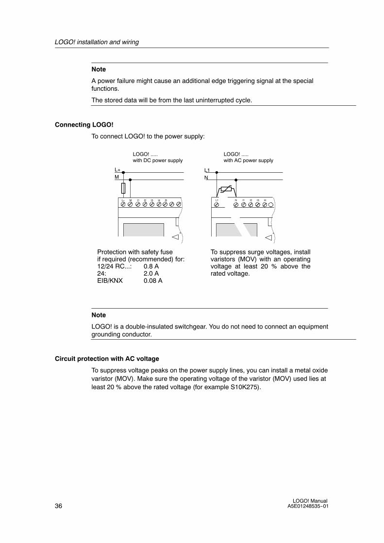
Connecting LOGO!
To connect LOGO! to the power supply:
L1L+
NM
LOGO! .....with DC power supply
LOGO! .....with AC power supply
Protection with safety fuseif required (recommended) for:12/24 RC...: 0.8 A24: 2.0 AEIB/KNX 0.08 A
To suppress surge voltages, installvaristors (MOV) with an operatingvoltage at least 20 % above therated voltage.
ML+ I1 I2 I3 I4 I5 I1 I2 I3 I4L1 N
Note
LOGO! is a double-insulated switchgear. You do not need to connect an equipmentgrounding conductor.
Circuit protection with AC voltage
To suppress voltage peaks on the power supply lines, you can install a metal oxidevaristor (MOV). Make sure the operating voltage of the varistor (MOV) used lies atleast 20 % above the rated voltage (for example S10K275).

LOGO! installation and wiring
37LOGO! ManualA5E01248535--01
2.3.2 Connecting the LOGO! TD power supply
The LOGO! TD must be connected to an external power supply that supplies avoltage of 12 V DC or 24 V AC/DC. A power connector is included with the LOGO!TD.
(1) Power supply(2) Communication interface
The power connection is non-polar; the ground can be connected on either the leftor right side.
Note
Siemens recommends that you protect the LOGO! TD with a 0.5 A safety fuse onthe power supply.

LOGO! installation and wiring
38LOGO! Manual
A5E01248535--01
2.3.3 Connecting LOGO! inputs
Requirements
At the inputs you connect sensor elements such as: momentary switches,switches, light barriers, daylight control switches etc.
Sensor characteristics for LOGO!
LOGO! 12/24 RC/RCo LOGO! 24/24o LOGO!DM812/24R
LOGO!DM8 24
I3 ... I6 I1,I2,I7,I8 I3 ... I6 I1,I2,I7,I8 I1 ... I8 I1 ... I8
Signal status 0 < 5 V DC < 5 V DC < 5 V DC < 5 V DC < 5 V DC < 5 V DC
Input current < 0.85 mA < 0.05 mA < 0.85 mA < 0.05 mA < 0.85 mA < 0.85 mA
Signal status 1 > 8.5 V DC > 8.5 V DC > 12 V DC > 12 V DC > 8.5 V DC > 12 V DC
Input current > 1.5 mA > 0.1 mA > 2 mA > 0.15 mA > 1.5 mA > 2 mA
LOGO! 24RC/RCo (AC)LOGO! DM824 R (AC)
LOGO! 24RC/RCo (DC)LOGO! DM824 R (DC)
LOGO! 230RC/RCo (AC)LOGO! DM8230 R (AC)
LOGO! 230RC/RCo (DC)LOGO! DM8230 R (DC)
Signal status 0 < 5 V AC < 5 V DC < 40 V AC < 30 V DCg
Input current < 1.0 mA < 1.0 mA < 0.03 mA < 0.03 mA
Signal status 1 > 12 V AC > 12 V DC > 79 V AC > 79 V DCg
Input current > 2.5 mA > 2.5 mA > 0.08 mA > 0.08 mA
LOGO! DM1624 R
LOGO! DM16 24 LOGO! DM16230 R (AC)
LOGO! DM16230 R (DC)
Signal status 0 < 5 V DC < 5 V DC < 40 V AC < 30 V DCg
Input current < 1.0 mA < 1.0 mA < 0.05 mA < 0.05 mA
Signal status 1 > 12 V DC > 12 V DC > 79 V AC > 79 V DCg
Input current > 2.0 mA > 2.0 mA > 0.08 mA > 0.08 mA
Note
The digital inputs of LOGO! 230 RC/RCo and of expansion module DM16 230Rare divided into two groups, each consisting of four inputs.Within the same group,all inputs must be operated on the same phase. Different phases are onlypossible between the groups.
Example: I1 to I4 on phase L1, I5 to I8 on phase L2.
Inputs within the LOGO! DM8 230R may not be connected to different phases.
LOGO! installation and wiring
39LOGO! ManualA5E01248535--01
Sensor connections
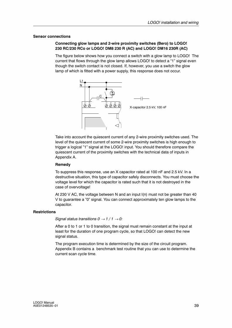
Connecting glow lamps and 2-wire proximity switches (Bero) to LOGO!230 RC/230 RCo or LOGO! DM8 230 R (AC) and LOGO! DM16 230R (AC)
The figure below shows how you connect a switch with a glow lamp to LOGO! Thecurrent that flows through the glow lamp allows LOGO! to detect a “1” signal eventhough the switch contact is not closed. If, however, you use a switch the glowlamp of which is fitted with a power supply, this response does not occur.
L1N
NL1
C
X-capacitor 2.5 kV, 100 nF
Take into account the quiescent current of any 2-wire proximity switches used. Thelevel of the quiescent current of some 2-wire proximity switches is high enough totrigger a logical ”1” signal at the LOGO! input. You should therefore compare thequiescent current of the proximity switches with the technical data of inputs inAppendix A.
Remedy
To suppress this response, use an X capacitor rated at 100 nF and 2.5 kV. In adestructive situation, this type of capacitor safely disconnects. You must choose thevoltage level for which the capacitor is rated such that it is not destroyed in thecase of overvoltage!
At 230 V AC, the voltage between N and an input I(n) must not be greater than 40V to guarantee a ”0” signal. You can connect approximately ten glow lamps to thecapacitor.
Restrictions
Signal status transitions 0 ! 1 / 1 ! 0:
After a 0 to 1 or 1 to 0 transition, the signal must remain constant at the input atleast for the duration of one program cycle, so that LOGO! can detect the newsignal status.
The program execution time is determined by the size of the circuit program.Appendix B contains a benchmark test routine that you can use to determine thecurrent scan cycle time.

LOGO! installation and wiring
40LOGO! Manual
A5E01248535--01
Special features of LOGO! 12/24 RC/RCo and LOGO! 24/24o
Fast digital inputs: I3, I4, I5 and I6:
These versions are also equipped with fast digital inputs (up/down counters,threshold triggers). The restrictions mentioned earlier do not apply to these fastdigital inputs.
Note
The fast digital inputs I3, I4, I5 and I6 are the same as in the previous versions0BA0 to 0BA5; therefore, a circuit program that is written in these versions can betransferred to the new 0BA6 devices with the programming software LOGO!SoftComfort, without any changes to these features. In contrast to this, you need tomodify circuit programs written for a LOGO!...L version (fast digital inputs I11/I12).The fast digital inputs have increased from 2 kHz to 5 kHz with the 0BA6 series.
Expansion modules do not have fast digital inputs.
Analog inputs: I1 and I2, I7 and I8:
The inputs I1, I2, I7 and I8 of LOGO! versions 12/24RC/RCo and24/24o can be used as either digital inputs or analog inputs. The input mode isdefined in the LOGO! circuit program.
The inputs I1, I2, I7 and I8 provide digital inputs, and the inputs AI3, AI4, AI1 andAI2 provide analog inputs, as described in Chapter 4.1. AI3 corresponds to theinput terminal I1; AI4 corresponds to I2; AI1 corresponds to I7; AI2 corresponds toI8. The use of AI3 and AI4 is optional. You configure your LOGO! to use either twoor four analog inputs as described in section 5.2.4.
When using inputs I1, I2, I7 and I8 as analog inputs, only the range from 0 to 10 VDC is available.
Connecting a potentiometer to inputs I1, I2, I7 and I8
To allow you to achieve 10 V as the maximum value when you completely turn thepotentiometer once, you must connect a series resistor on the potentiometer’sinput side regardless of the input voltage (see figure below).
We suggest the following sizes of potentiometers and associated series resistors:
Voltage Potentiometer Series Resistor
12 V 5 kΩ --
24 V 5 kΩ 6.6 kΩ
When using a potentiometer and 10 V input voltage as the maximum value, youmust ensure that with a connected input voltage of 24 V, 14 V must release via theseries resistor so that a maximum of 10 V are supplied when you turn thepotentiometer one full rotation. With a voltage of 12 V, this can be neglected.
LOGO! installation and wiring
41LOGO! ManualA5E01248535--01
Note
The LOGO! AM 2 expansion module provides additional analog inputs. TheLOGO! AM 2 PT100 expansion module provides Pt100 inputs.
Always use twisted and shielded cables for analog signals, and keep these asshort as possible.
Sensor connections
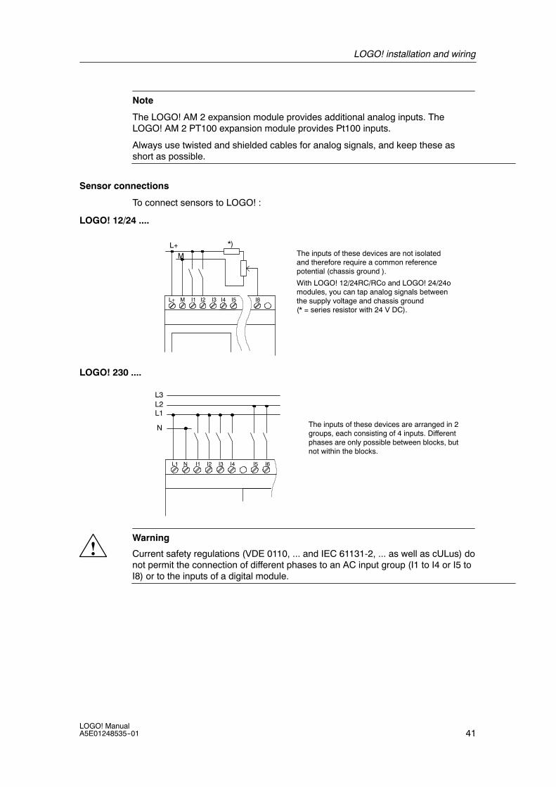
To connect sensors to LOGO! :
LOGO! 12/24 ....
L+M The inputs of these devices are not isolated
and therefore require a common referencepotential (chassis ground ).
With LOGO! 12/24RC/RCo and LOGO! 24/24omodules, you can tap analog signals betweenthe supply voltage and chassis ground(* = series resistor with 24 V DC).
ML+ I1 I2 I3 I4 I5 I8
*)
LOGO! 230 ....
L1
N
L3L2
The inputs of these devices are arranged in 2groups, each consisting of 4 inputs. Differentphases are only possible between blocks, butnot within the blocks.
NL1 I1 I2 I3 I4 I5 I6
!Warning
Current safety regulations (VDE 0110, ... and IEC 61131-2, ... as well as cULus) donot permit the connection of different phases to an AC input group (I1 to I4 or I5 toI8) or to the inputs of a digital module.

LOGO! installation and wiring
42LOGO! Manual
A5E01248535--01
LOGO! AM 2
Current measurement Voltage measurement
ML+
L+M
Current
U1 I2 M2 U2I1 M1
PE
L+M
Reference
current0...20 mA
1
2
1
PE
Earth
Cable shielding
PE terminal for connectingearth and shielding theanalog measuring cable
3 3 DIN railRUN/STOP
2
M
ML+
0 -- 10 V
The illustration above shows an example of four-wire current measurement andtwo-wire voltage measurement.
Connecting a two-wire sensor to the LOGO! AM 2
Wire up the two-wire sensor’s connecting wires as follows:
1. Connect the sensor’s output to connection U (0 ... 10 V voltage measurement)or to connection I (0 ... 20 mA current measurement) of the AM 2 module.
2. Connect the plus connector on the sensor to the 24 V supply voltage (L+).
3. Connect the ground connection on the sensor to the corresponding M input (M1or M2) on the AM 2 module.

LOGO! installation and wiring
43LOGO! ManualA5E01248535--01
LOGO! AM 2 PT100
You can connect either a 2- or 3-wire Pt100 resistive thermocouple to the module.
For a 2-wire connection, you need to short-circuit terminals M1+ and IC1 or M2+and IC2. Errors caused by the ohmic resistance of the measuring line are notcompensated for this type of connection. A line resistance of 1 Ω is proportional toa measuring error of +2.5 ˚C.
A 3-wire technique suppresses the influence of the cable length (ohmic resistance)on the result of the measurement.
M1+
PE
L+ M
RUN/STOP
L+ M
IC1 IC2M1- M2+ M2-
Pt100
M1+
PE
L+ M
RUN/STOP
L+ M
IC1 IC2M1-M2+ M2-
Pt100
2-wire technique 3-wire technique
Note
Fluctuating analog values are due to screening on the connecting wire from theanalog valuator device to the analog AM 2 / AM 2 PT100 LOGO! expansionmodule (encoder wire) that has either been mounted incorrectly or not at all.
To avoid fluctuating analog values when using these expansion modules, proceedas follows:
• Use only shielded encoder wires.
• Shorten the encoder wire as much as possible. The encoder wire must not bemore than 10 meters long.
• Clamp the encoder wire on one side only and clamp it only to the PE terminalon the AM 2 / AM 2 PT100 / AM 2 AQ expansion module.
• Connect ground on the encoder supply to the PE terminal on the expansionmodule.
• Avoid operating the LOGO! AM 2 PT100 expansion module with a powersupply that is not grounded (potential-free). If you cannot avoid this, connectthe negative output/ground output on the power supply to the shielding on theresistance thermometer’s measuring wires.

LOGO! installation and wiring
44LOGO! Manual
A5E01248535--01
2.3.4 Connecting outputs
LOGO! ...R...
The LOGO! ...R... version is equipped with relay outputs. The potential of the relaycontacts is isolated from the power supply and the inputs.
Requirements for relay outputs
You can connect various loads to the outputs, e.g. lamps, fluorescent lamps,motors, contactor relays etc. For information on the properties required for theloads connected to LOGO! ...R..., refer to Appendix A.
Connecting
This is how you connect the load to LOGO! ...R...:
Protection with automatic circuit-breaker, max. 16 A, characteristicsB16, e.g.: Power circuit-breaker 5SX2 116-6 (if required)
DM8...R
1 2Q1 Q2
1 2
Q5 Q61 2 1 2
Load Load
LOGO! with solid-state outputs
LOGO! versions with solid-state outputs can be identified by the fact that the letterR is missing from their type name. The outputs are short circuit-proof andoverload-proof. An auxiliary load voltage supply is not necessary, because LOGO!supplies the load voltage.

LOGO! installation and wiring
45LOGO! ManualA5E01248535--01
Requirements for solid-state outputs
The load connected to LOGO! must have the following characteristics:
• The maximum switched current is 0.3 A per output.
Connecting
This is how you connect the load to a LOGO! with solid-state outputs:
Load: 24 V DC, 0.3 A max.
DM8 24
Q1 Q2M M
Q5 Q6M M
Load Load
LOGO! AM 2 AQ
1 Earth
DIN rail2
V1+ V2+
RUN/STOP
M2M1
L+ ML+ M
OUTPUT 2x(0..10V) or0/4..20mA
PE
0/4--20mA0-10 V
R1 R2
1
V1, V2: 0 - 10 V DCR1: >= 5 kΩ
I1, I2: 0/4 - 20 mAR2: <= 250 Ω
2
I1 I2
L+
M
The illustration above shows an example of how to connect the voltage or currentload.

LOGO! installation and wiring
46LOGO! Manual
A5E01248535--01
2.3.5 Connecting the EIB bus
The connection is carried out via the two-pole screw terminal (+ and --).
+ -- EIB
Prog. ↓
RUN/STOP
BUS
Only the red-black core pair is used, the white-yellow core pair is not connected.
Press the button “Prog ↓” to switch the CM EIB/KNX to programming mode.
Note
The button “Prog ↓” should not be pressed too firmly.
If the bus connection is OK, the LED lights up green.
In programming mode, the LED lights up orange.
Networking on the EIB bus
The CM EIB/KNX takes over the communication between LOGO! and EIB andmakes communication available via EIB inputs/outputs.
The application of the CM EIB/KNX fills the complete LOGO! process image; thatis, inputs or outputs which are not occupied on LOGO! can be occupied on the EIB.
Note
For detailed information about the networking of LOGO! on the EIB bus pleaserefer to the LOGO! CM EIB/KNX documentation, in particular the Micro AutomationSet 8.
LOGO! installation and wiring
47LOGO! ManualA5E01248535--01
2.3.6 Connecting the AS interface bus
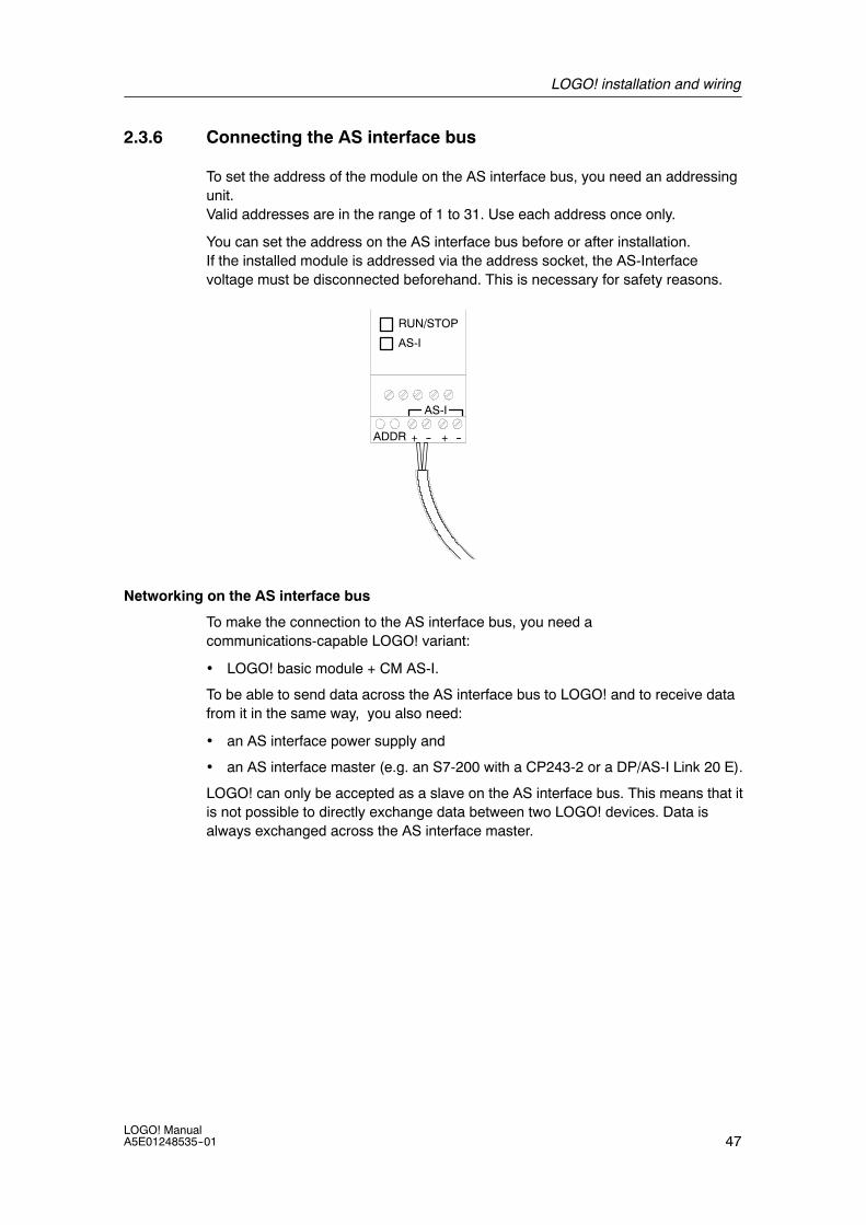
To set the address of the module on the AS interface bus, you need an addressingunit.Valid addresses are in the range of 1 to 31. Use each address once only.
You can set the address on the AS interface bus before or after installation.If the installed module is addressed via the address socket, the AS-Interfacevoltage must be disconnected beforehand. This is necessary for safety reasons.
+ --ADDR
RUN/STOP
AS-I
+ --
AS-I
Networking on the AS interface bus
To make the connection to the AS interface bus, you need acommunications-capable LOGO! variant:
• LOGO! basic module + CM AS-I.
To be able to send data across the AS interface bus to LOGO! and to receive datafrom it in the same way, you also need:
• an AS interface power supply and
• an AS interface master (e.g. an S7-200 with a CP243-2 or a DP/AS-I Link 20 E).
LOGO! can only be accepted as a slave on the AS interface bus. This means that itis not possible to directly exchange data between two LOGO! devices. Data isalways exchanged across the AS interface master.
LOGO! installation and wiring
48LOGO! Manual
A5E01248535--01
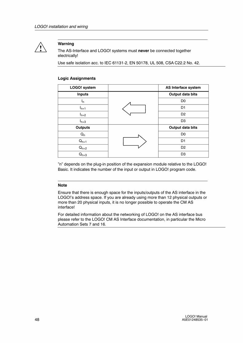
!Warning
The AS-Interface and LOGO! systems must never be connected togetherelectrically!
Use safe isolation acc. to IEC 61131-2, EN 50178, UL 508, CSA C22.2 No. 42.
Logic Assignments
LOGO! system AS Interface system
Inputs Output data bits
In D0
In+1 D1
In+2 D2
In+3 D3
Outputs Output data bits
Qn D0
Qn+1 D1
Qn+2 D2
Qn+3 D3
”n” depends on the plug-in position of the expansion module relative to the LOGO!Basic. It indicates the number of the input or output in LOGO! program code.
Note
Ensure that there is enough space for the inputs/outputs of the AS interface in theLOGO!’s address space. If you are already using more than 12 physical outputs ormore than 20 physical inputs, it is no longer possible to operate the CM ASinterface!
For detailed information about the networking of LOGO! on the AS interface busplease refer to the LOGO! CM AS Interface documentation, in particular the MicroAutomation Sets 7 and 16.

LOGO! installation and wiring
49LOGO! ManualA5E01248535--01
2.4 Putting into operation
2.4.1 Switching on the LOGO!/Power On
LOGO! does not have a power switch. The reaction of LOGO! during startupdepends on the following:
• Whether a circuit program is stored in LOGO!
• Whether a memory card or combined memory/battery card is inserted
• Whether this is a LOGO! version without display unit (LOGO!...o)
• The status of LOGO! at the time of power failure.
All possible reactions of LOGO! are described on the following page.
To ensure that the expansion module on LOGO! changes to RUN mode, check thefollowing:
• Has the sliding contact between LOGO! and the expansion module snappedinto place properly?
• Is the power supply connected to the expansion module?
• In addition, always ensure that you switch on the power supply to the expansionmodule first before activating the power supply to the LOGO! basic module (oractivate both power supplies at the same time); if you do not do this, the systemdoes not detect the expansion module when you start up the LOGO! basicmodule.

LOGO! installation and wiring
50LOGO! Manual
A5E01248535--01
>Program..Card..Setup..Start
>Program..Card..Setup..Start
2008-05-05Mo 09:00
>Program..Card..Setup..Start
2002-01-31with stored programfrom LOGO!
&
B1
Q1
No program inmemory
(empty)
(with program)
or
LOGO!in RUN mode
or
Program inmemory
with a program copiedfrom the memory card orcombined memory/batterycard in LOGO!
Before power off After power on
with stored programfrom LOGO!
with program copiedfrom the memory cardor combinedmemory/battery card inLOGO!
2003-01-27Mo 09:00
No programPress ESC
LOGO! in RUN mode
No ProgramPress ESC
Mo 09:00
I:0.. 1234567891..01234567892..01234
Q:0..1234567891..0123456
0.. 1234567891..01234567892..01234
I:
B3:
Cnt = 0028
Par = 0300
0.. 1234567891..01234567892..01234
I:
(empty)
(with program)
or
(empty)
(with program)
You can also memorize four simple rules for starting LOGO! :
1. If neither LOGO! nor the inserted memory card or combined memory/batterycard contains a circuit program, LOGO! (with display unit) reports: ’No Program/ Press ESC’.
2. A circuit program on the memory card or combined memory/battery card isautomatically copied to LOGO!. The circuit program in LOGO! is overwritten.
3. If there is a circuit program in LOGO! or on the memory card or combinedmemory/battery card, LOGO! adopts the operational state it had prior toPOWER-OFF. Versions without display unit (LOGO!...o) automatically changefrom STOP to RUN (LED changes from red to green).
4. If you have enabled retentivity for at least one function, or a function ispermanently retentive, the current values are retained at POWER-OFF.

LOGO! installation and wiring
51LOGO! ManualA5E01248535--01
Note
When a power failure occurs while you are entering a circuit program, the programin LOGO! will be deleted after power is returned.
Before you modify the circuit program, save a backup copy of your original to amemory card, a combined memory/battery card or to a computer (LOGO!SoftComfort).
2.4.2 Putting a CM EIB/KNX into operation
1. Bus voltage and supply voltage must be present.
2. Connect the PC to the serial EIB interface.
3. Start software ETS, using ETS2 version 1.2.
4. Configure the application program in ETS2, V 1.2.
5. The application program is loaded into the devices via the EIB interface. Theapplication program is available on the LOGO! home page(http://www.siemens.de/logo).
6. Click on ”Program Physical Address” in ETS.
7. Press the button of the CM EIB/KNX to switch the CM EIB/KNX to programmingmode; LED lights up orange.
Note
The button “Prog ↓” should not be pressed too firmly.
If the bus connection is OK, the LED lights up green.
In programming mode, the LED lights up orange.
8. If the LED is extinguished, the programming of the physical address hasfinished. You can now mark the physical address on the device. Composition ofthe physical address:Area / Line / Device XX / XX / XXX
9. The application program can now be run. The device is then ready foroperation.
10.If several CM EIB/KNX are installed in an EIB system, steps 1 to 9 must berepeated for each CM EIB/KNX.
11.Any further details about EIB commissioning can be found in the correspondingdocumentation.

LOGO! installation and wiring
52LOGO! Manual
A5E01248535--01
2.4.3 Operating states
LOGO! Basic operating states
LOGO! Basic/Pure knows has two operating states: STOP and RUN.
STOP RUN
• The display shows: ’No Program’(not LOGO!...o)
• Switching LOGO! to programming mode(not LOGO!...o)
• LED is red(only LOGO!...o)
• Display: Screen mask for monitoringI/Os and messages (after START in themain menu)(not LOGO!...o)
• Switching LOGO! to parameterassignment mode(not LOGO!...o)
• LED is green(only LOGO!...o)
Action of LOGO!:
• The input data is not read.
• The circuit program is not executed.
• The relay contacts are permanentlyopen or the solid-state outputs areswitched off.
Action of LOGO!:
• LOGO! reads the status of the inputs.
• LOGO! uses the circuit program tocalculate the status of the outputs.
• LOGO! switches the relay/solid-stateoutputs on or off.
Note
After switching the power on, the system briefly switches through the outputs onthe LOGO 24/24o. With an open circuit, a voltage of > 8 V can occur for up toapproximately 100 ms; when loaded, this time reduces to a matter ofmicroseconds.
LOGO! expansion modules, operating states
LOGO! expansion modules have three operating states: The LED (RUN/STOP) islit green, red or orange.
LED (RUN/STOP) is lit
Green (RUN) Red (STOP) Orange/Yellow
The expansion modulecommunicates with thedevice to the left.
The expansion module doesnot communicate with thedevice to its left.
Initialization phase of theexpansion module

LOGO! installation and wiring
53LOGO! ManualA5E01248535--01
CM AS Interface, communication states
The CM AS Interface has three communication states: The LED is lit green, red orflashes red/yellow.
LED AS-I is lit
Green Red Red/Yellow
AS Interface communicationOK
AS Interface communicationfailed
Slave has address ”0”.
CM AS Interface, behavior on communication failure
• If the AS Interface voltage fails, communication between the LOGO! system andthe expansion modules, which are arranged to the right of the LOGO! CM ASInterface expansion module, is interrupted.Recommendation: Position LOGO! CM AS Interface on the far right side.
• If communication is interrupted, the switching outputs are reset after about 40 to100 ms.
CM EIB/KNX, communication states
The CM EIB/KNX has three communication states: The LED is lit green, red ororange.
LED BUS is lit
Green Red Orange
Bus connection OK,communication OK,no programming mode
Bus connection interrupted Programming mode activeand bus connection OK
CM EIB/KNX, behavior on communication failure
• LOGO! voltage failureIf there is a power failure of LOGO! or a disruption in the communication to theLOGO! master or to the communication partner on the left side, the outputs areset to 0. The RUN/STOP LED lights up red after a second.
• LOGO! voltage recoveryLOGO! starts up again, CM EIB/KNX sends the parameterized states.
• CM EIB/KNX voltage failureAll the inputs of the LOGO! master on the EIB are set to 0 by the LOGO!master.
• CM EIB/KNX voltage recoveryAll the outputs of the LOGO! master on the EIB are updated. The inputs areread by the EIB depending on the parameterization.
• Short circuit on the bus or bus interruptionThe behavior can be parameterized in the LOGO! configuration window of theapplication program in ETS (EIB Tool Software). The red light is set after 5 s.
• Bus recoveryThe behavior can be parameterized in the LOGO! configuration window.

LOGO! installation and wiring
54LOGO! Manual
A5E01248535--01

55LOGO! ManualA5E01248535--01
Programming LOGO!
Getting started with LOGO!
Programming refers to creating a circuit program from the LOGO! Basic module.
In this chapter you will learn how to use LOGO! to create the LOGO! circuitprograms for your application.
LOGO!Soft Comfort is the LOGO! programming software that you can use on yourPC to quickly and easily create, test, modify save and print the circuit programs.The topics in this manual, however, relate only to the creation of circuit programson the actual LOGO! Basic module. The programming software LOGO!SoftComfort contains extensive online help. See also Chapter 7 for additionalinformation.
Note
LOGO! versions without a display unit; that is, the LOGO! 24o, LOGO! 12/24RCo,LOGO! 24RCo and LOGO! 230RCo versions, do not have an operator panel anddisplay unit. They are primarily designed for use in small machine and processequipment engineering systems for series production.
LOGO!...o versions are not programmed directly on the device. Instead, the circuitprogram is downloaded to the device from LOGO!Soft Comfort or from memorycards or combined memory/battery cards from other LOGO! devices.
LOGO! versions without a display cannot write data to memory cards or combinedmemory/battery cards.See Chapters 6, 7 and Appendix C.
A small example in the first part of this chapter introduces the operating principlesof LOGO!:
• You will learn the meaning of two basic terms, namely the connector and theblock.
• As the next step, you will create a circuit program based on a simpleconventional circuit.
• Lastly, you will enter this program directly in LOGO!
It will take you only a few pages of this manual to store your first executable circuitprogram in the LOGO! unit. With suitable hardware (switches etc.), you will then beable to carry out initial tests.
3

Programming LOGO!
56LOGO! Manual
A5E01248535--01
3.1 Connectors
LOGO! is equipped with inputs and outputs
Example of a configuration with several modules:
AI4
1 2 1 2 1 2 1 2
L+ M I13I14I15I16
Q11
Q9
Q12
Q10
RUN/STOP
L+ M
AI5
RUN/STOP
L+ M AI3 I3 I4 I5 I6
Q1 Q2 Q3 Q4
Inputs
Outputs
AI1 AI2 L+ M I9 I10 I11I12
Q7
Q5
Q8
Q6
RUN/STOP
M3U3AI6M4U4
Analog inputs
1 2 1 2
1 2 1 2 1 2 1 2
1 2 1 2
PE
INPUT 2x (..10 V/..20 mA)
L+ M
Each input is identified by the letter I plus a number. When you look at LOGO! fromthe front, you can see the input terminals at the top. Only analog modules LOGO!AM 2 and AM 2 PT100 have the inputs at the bottom.
Each output is identified by the letter Q plus a number (AM 2 AQ: AQ plus number).In the figure, you can see the output terminals at the bottom.
Note
LOGO! can recognize, read and switch the I/O of all expansion modulesregardless of their type. The I/Os are presented in the installation order of themodules.
The following I/Os and flag blocks are available for creating your circuit program: :I1 to I24, AI1 to AI8, Q1 to Q16, AQ1 and AQ2, M1 to M27 and AM1 to AM6. Alsoavailable are the shift register bits S1 to S8, 4 cursor keys: C Y, C ", C B and C A,four function keys on the LOGO! TD: F1, F2, F3, and F4 as well as 16 blankoutputs X1 to X16. See Chapter 4.1 for more details.
The following applies to inputs I1, I2, I7 and I8 of LOGO! 12/24.. and LOGO!24/24o versions: If you use I1, I2, I7 or I8 in the circuit program, this input signal isdigital. If you use AI3, AI4, AI1, or AI2, the input signal is analog. The numbering ofthe analog inputs is significant: AI1 and AI2 corresponded to I7 and I8 on the 0BA5module. With the addition of two new analog inputs for the 0BA6 series, thesemodules optionally use I1 for AI3 and I2 for AI4. See the graphical representationat 2.1.1. Also note that you can also use I3, I4, I5, and I6 as fast digital inputs.
The illustration above with numbered AI inputs shows the conceptual usage of theinputs, not the actual physical markings on the module.

Programming LOGO!
57LOGO! ManualA5E01248535--01
LOGO!’s connectors
The term connector refers to all connections and states in LOGO! .
The digital I/O status can be ’0’ or ’1’. Status ’0’ means that the input does not carrya specific voltage. Status ’1’ means that the input does carry a specific voltage.
The ’hi’, ’lo’ and ’x’ connectors have been introduced to make it easier for you tocreate the circuit program:’hi’ (high) is assigned the status ’1’,’lo’ (low) is assigned the status ’0’.
You do not have to use all of the connectors of a block. The circuit programautomatically assigns the unused connectors a status that ensures properfunctioning of the relevant block. If you prefer to do so, you can identify unusedconnectors with an ’x’.
For information on the meaning of the term “block”, refer to Chapter 3.3.
LOGO! has the following connectors:
ConnectorsLOGO! Basic / Pure DM AM AM2AQ
Inputs LOGO! 230RC/RCo,LOGO! 24 RC/RCo
Two groups:I1... I4 andI5 ... I8
I9 ...I24
AI1...AI8
none
LOGO!12/24RC/RCo,LOGO! 24/24o
I1,I2, I3--I6, I7, I8
AI3,AI4 ...AI1, AI2
I9 ...I24 AI5...
AI8
Outputs Q1...Q4 Q5 ...Q16
none AQ1,AQ2
lo Logical ’0’ signals (off)
hi Logical ’1’ signals (on)
x An existing connection that is not used
DM: Digital moduleAM: Analog module

Programming LOGO!
58LOGO! Manual
A5E01248535--01
3.2 EIB inputs/outputs
The application program “20 CO LOGO! 900E02” controls the communicationbetween the LOGO! and the EIB/KNX bus via the communication module CMEIB/KNX.
By configuring the application program in ETS (EIB Tool Software), the division ofthe input and output area of the LOGO! can be defined as a “hardware channel”and as a “virtual channel” on the EIB/KNX bus.This characteristic also applies for analog processing.
A communication object is assigned to each “hardware channel” and each “virtualchannel“ of LOGO! module.The real-time clock of LOGO! can be used as a master or slave via the EIB/KNXbus.
The behavior of the communication objects of the communication module CMEIB/KNX, when the status of the EIB/KNX bus changes, can also beparameterised.
A “virtual input channel“ can be used as a bus state; that is, a bus voltage failurecan be reported.
The settings for analog values in LOGO! (Offset, Gain) do not affect the analogvalues for the CM EIB/KNX communication module (the output values of the CMEIB/KNX are always the raw values between 0 and 1000). In this case, you mustparameterize customizing in the ETS.
Functions of the application program
• Specification of the hardware configuration (number of local digital inputs andoutputs, analog inputs)
• Selection of time master or slave
• Use of I24 as a bus status signal
• Behavior on bus voltage failure/recovery
• Input type as monoflop/normal for digital inputs via the EIB/KNX
• Output type as normal/dimmer/edge evaluation for digital outputs via theEIB/KNX
• Data type, adaptation, cyclical sending and sending on change in value foranalog outputs via the EIB/KNX and analog inputs on LOGO!
Any further details about configuring the application program in ETS can be foundin the current application program description.
For the application program see Siemens product database from version Jonwardsor: http://www.siemens.de/gamma
http://www.siemens.de/logo
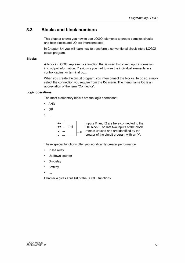
Programming LOGO!
59LOGO! ManualA5E01248535--01
3.3 Blocks and block numbers
This chapter shows you how to use LOGO! elements to create complex circuitsand how blocks and I/O are interconnected.
In Chapter 3.4 you will learn how to transform a conventional circuit into a LOGO!circuit program.
Blocks
A block in LOGO! represents a function that is used to convert input informationinto output information. Previously you had to wire the individual elements in acontrol cabinet or terminal box.
When you create the circuit program, you interconnect the blocks. To do so, simplyselect the connection you require from the Co menu. The menu name Co is anabbreviation of the term “Connector”.
Logic operations
The most elementary blocks are the logic operations:
• AND
• OR
• ...
I1
I2
x
²1Inputs I1 and I2 are here connected to theOR block. The last two inputs of the blockremain unused and are identified by thecreator of the circuit program with an ’x’.
Qx
These special functions offer you significantly greater performance:
• Pulse relay
• Up/down counter
• On-delay
• Softkey
• ....
Chapter 4 gives a full list of the LOGO! functions.

Programming LOGO!
60LOGO! Manual
A5E01248535--01
Block representation on the LOGO! display
The figure below shows a typical view of the LOGO! display. As you can see, it canshow only one block at a time. We have therefore introduced block numbers tohelp you check the circuit structure.
≥1B2I3 Q1
B1
View of the LOGO! display
x
Block number -assigned by LOGO!
Another block isconnected at this point
Input
This connector is not required OutputBlock
x
Assigning a block number
LOGO! assigns each new block in a circuit program a block number.
LOGO! uses these block numbers to indicate the block interconnections. Thismeans that these numbers are mainly an aid to your orientation in the circuitprogram.
I1I2I3
≥1
B1
B2
B2≥1
B3 Q1
B1
B1
Scrolling the circuit program using the key
I4I5I6
≥1
B1
These blocks areinterconnected
Block numbers
Q1x
B3
x
x x
The figure above shows you three views of the LOGO! display, which represent thecircuit program. As you can see, LOGO! interconnects the blocks using theirnumbers.

Programming LOGO!
61LOGO! ManualA5E01248535--01
Advantages of block numbers
You can connect almost any block to an input of the current block by means of itsblock number. In this way, you can reuse the interim results of logical or otheroperations, reduce programming effort, save memory space and clean up yourcircuit layout. To do so, however, you need to know how LOGO! has named theblocks.
Note
We advise you to create an organizational program chart. You will find this avaluable aid when you create the circuit program because you can enter in thischart all the block numbers that LOGO! assigns.
By using the LOGO!Soft Comfort software to program LOGO!, you can directlycreate a function chart of your circuit program. LOGO!Soft Comfort also allows youto assign eight-character names to up to 100 blocks, and to view these on theLOGO! display in parameter assignment mode (see Chapter 3.5).

Programming LOGO!
62LOGO! Manual
A5E01248535--01
3.4 From circuit diagram to LOGO! program
View of a circuit diagram
You know, of course, how a circuit logic is represented in a circuit diagram.Nevertheless, here is an example:
K1
S1 K1S2
E1
Load E1 is switched on and off bymeans of the switches (S1 OR S2)AND S3.
S3Relay K1 picks up when condition(S1 OR S2) AND S3 is met.
Creating this circuit with LOGO!
In LOGO! you create a circuit logic by interconnecting blocks and connectors:
S1 ... S3Wiring of the inputs
I3
xQ1
&≥1I1I2x
Circuit program in LOGO!
Wiring of the outputs
L1
N

Programming LOGO!
63LOGO! ManualA5E01248535--01
Note
Although you have four inputs available for logic operations (Basic functions, seeChapter 4.2), most of the views will only show three inputs for reasons of clarity.You program this fourth input and assign parameters just like you do with the otherthree inputs.
To create a circuit logic in LOGO!, start at the circuit output.
The output is the load or relay that is to be switched.
Convert the circuit logic into blocks by working through the circuit, starting at theoutput and ending at the input:
Step 1: The make contact S3 is interconnected in series to output Q1 and to afurther circuit element. A series connection corresponds with the AND block:
I3
xQ1
&
Step 2: S1 and S2 are connected in parallel. A parallel circuit corresponds with theOR block:
I3
xQ1
&≥1I1I2x
Unused inputs
The circuit program automatically assigns the unused connectors a status thatensures proper functioning of the relevant block. If you like, you can label unusedconnectors with an ’x’ identifier.
In our example we shall use only two inputs of the OR block and two inputs of theAND block; the relevant unused third and fourth inputs are identified at theconnector with an ’x’.
Now connect the I/Os to LOGO! .
Wiring
Connect the switches S1 to S3 to the screw terminals of your LOGO! :
• S1 to connector I1 of LOGO!
• S2 to connector I2 of LOGO!
• S3 to connector I3 of LOGO!
The output of the AND block controls the relay at output Q1. The load E1 isconnected to output Q1.

Programming LOGO!
64LOGO! Manual
A5E01248535--01
Wiring example
The following figure shows you the wiring, based on a 230 V AC version of LOGO!.
L1
N
Input wiring
Output wiring
S3S2S1
L1
N
NL1 I1 I2 I3 I4
1 2Q1
Load
3.5 The four golden rules for operating LOGO!
Rule 1Changing the operating mode
• You create the circuit program in programming mode. After power is on, andwhen the display shows “No Program / Press ESC”, press the ESC key to selectprogramming mode.
• Timer and parameter values of an existing circuit program can be edited both inparameter assignment mode and in programming mode. During parameterassignment LOGO! is in RUN mode; that is, it continues executing the circuitprogram (see Chapter 5). To work in programming mode, you need toterminate the circuit program by calling the “Stop” command.
• Select the ’Start’ command on the main menu to set RUN mode.
• When the system is in RUN, you can return to parameter assignment modeby pressing the ESC key.
• When parameter assignment mode is open and you want to return toprogramming mode, select the “Stop” command from the parameterassignment menu, and confirm “Stop Prg” prompt with “Yes”. To do so, movethe cursor to “Yes” and confirm with OK.
For more details on operating modes, refer to Appendix D.

Programming LOGO!
65LOGO! ManualA5E01248535--01
Note
The following applies to 0BA2 device versions and earlier:
• You can open programming mode by pressingA+"+OK.
• You set parameter assignment mode by pressing ESC+OK.
Rule 2Outputs and inputs
• Always create your circuit program by working from the output to the input.
• You can connect an output to several inputs, but not the same input to severaloutputs.
• Within the same program path you may not connect an output to an upstreaminput. For such internal recursions you should interconnect flags or outputs.
Rule 3Cursor and cursor movement
The following applies when you edit a circuit program:
• You can move the cursor when it appears in the form of an underscore:
-- Press , , or to move the cursor in the circuit program.
-- Press OK to change to ”Select connector/block”.
-- Press ESC to exit programming mode.
• You select a connector/block
when the cursor appears as a solid square
-- Press or to select a connector or a block.
-- Confirm with OK.
-- Press ESC to return to the previous step.
Rule 4Planning
• Before you start to create a circuit program, you should either first create adesign on paper or program LOGO! directly using LOGO!Soft Comfort.
• LOGO! can only save complete and faultless circuit programs.
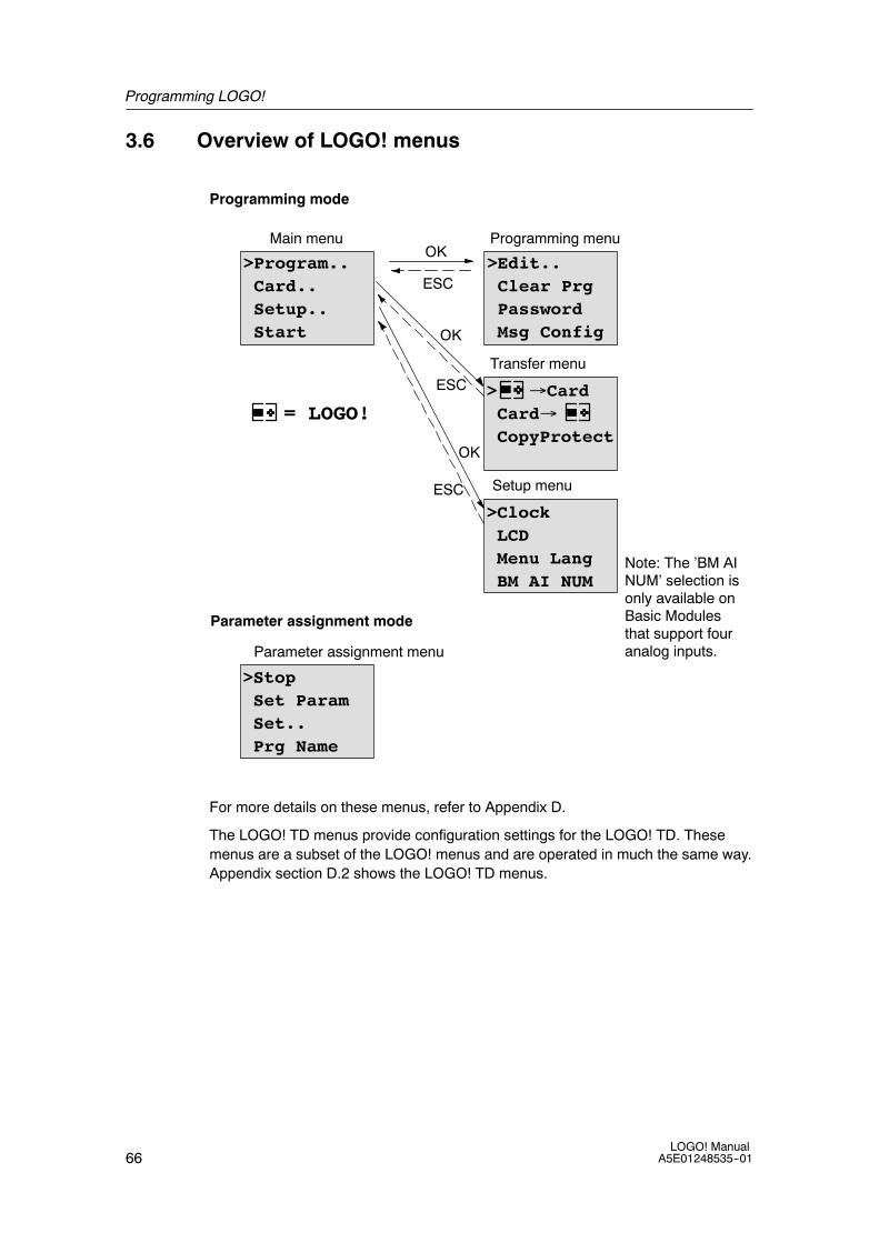
Programming LOGO!
66LOGO! Manual
A5E01248535--01
3.6 Overview of LOGO! menus
>Program..Card..Setup..Start
>Edit..Clear PrgPasswordMsg Config
> →CardCard→CopyProtect
Main menu Programming menu
Transfer menu
>StopSet ParamSet..Prg Name
OK
OK
ESC
ESC
Parameter assignment menu
Programming mode
Parameter assignment mode
= LOGO!
>ClockLCDMenu LangBM AI NUM
Setup menuESC
OK
Note: The ’BM AINUM’ selection isonly available onBasic Modulesthat support fouranalog inputs.
For more details on these menus, refer to Appendix D.
The LOGO! TD menus provide configuration settings for the LOGO! TD. Thesemenus are a subset of the LOGO! menus and are operated in much the same way.Appendix section D.2 shows the LOGO! TD menus.

Programming LOGO!
67LOGO! ManualA5E01248535--01
3.7 Writing and starting the circuit program
After you have designed a circuit, you want to write it to your LOGO! . The smallexample below shows how to do this.
3.7.1 Selecting programming mode
You have connected LOGO! to the power supply and switched it on. The displaynow shows you the message:
No ProgramPress ESC
Switch LOGO! to programming mode by pressing ESC. This will take you to themain menu of LOGO!:
>Program..Card..Setup..Start
LOGO!’s main menu
The first character in the first line is the ”>” cursor. Press and to move the ”>”cursor up and down. Move it to ”Program..” and confirm with OK. LOGO! opens theprogramming menu.
>Edit..Clear PrgPasswordMsg Config
LOGO!’s programming menu
Here you can also move the ”>” cursor by pressing and . Move the ”>” cursor to”Edit..” and confirm with OK.
>Edit PrgEdit NameAQMemory?
The Edit menu of LOGO!

Programming LOGO!
68LOGO! Manual
A5E01248535--01
Move the ”>” cursor to ”Edit Prg” (for editing the circuit program) and confirm withOK. LOGO! now shows you the first output:
The first output of LOGO!
Q1
You are now in programming mode. Press and to select the other outputs. Nowstart to edit your circuit program.
Note
Because we have not yet saved a password for the circuit program in LOGO!, youcan directly enter editing mode. When you select “Edit“ after you have saved apassword-protected circuit program, you are prompted to enter a password and toconfirm it with OK. You can only edit the program after you have entered thecorrect password (see Chapter 3.7.5.).
3.7.2 The first circuit program
Let us now take a look at the following parallel circuit consisting of two switches.
Circuit diagram
The corresponding circuit diagram:
K1
S1K1
S2
E1
The load is switched on withS1 OR S2. LOGO! interpretsthis parallel circuit as an ’OR’logic, because S1 OR S2switches on the output.
Translated into a LOGO! circuit program this means: Relay K1 is (at output Q1) iscontrolled by means of an OR block.
Circuit program
S1 is connected to the I1 and S2 to the I2 input connector of the OR block.
The corresponding layout of the circuit program in LOGO!:
I1
I2
xQ1
≥1

Programming LOGO!
69LOGO! ManualA5E01248535--01
Wiring
The corresponding wiring:
L1 N I4 I5 I6 I7 I8
Q1 Q2 Q3 Q4
L1
N
S1S2
L
N
I1I1 I3I1I1 I2
1 2 1 2 1 2 1 2
S1 switches input I1, while S2 switches input I2. The load is connected to the relayQ1.

Programming LOGO!
70LOGO! Manual
A5E01248535--01
3.7.3 Circuit program input
Let us now write the circuit program, starting at the output and working towards theinput. LOGO! initially shows the output:
The first LOGO! output
Q1
You will see an underscore below the Q in Q1, which is the cursor. The cursorindicates your current position in the circuit program. You can move the cursor bypressing the , , and keys. Now press the key. The cursor moves to theleft.
The cursor indicates your current position inthe circuit program.
Q1-
At this point you enter only the first (OR) block. Press OK to select editing mode.
The cursor is displayed as a solid square:You can now select a connector or a block
Q1Co
The cursor no longer appears in the form of an underscore; but instead as aflashing solid square. LOGO! offers you various options here.
Select GF (basic functions) by pressing the key until GF appears, and confirmwith OK. LOGO! now shows the first block from the list of basic functions:
The AND is the first block of the basicfunctions list. The solid square cursorprompts you to select a block.
&B1
Q1

Programming LOGO!
71LOGO! ManualA5E01248535--01
Now press or until the OR block appears on the display:
≥1B1
Q1The solid square cursor is stillpositioned on the block.
Press OK to confirm your entries and exit the dialog.
≥1
The display now shows:
B1
Q1
B1
≥1Q1
Your complete circuitprogram layout
Blocknumber-
You have now entered the first block. Each new block is automatically assigned ablock number. The only thing left to do is interconnect the block inputs. This is howit is done:
Press OK.
≥1
The display now shows:
B1
Q1Co
Select the Co list: Press OK
≥1
The display now shows:
B1
Q1x

Programming LOGO!
72LOGO! Manual
A5E01248535--01
The first element of the Co list is the ”Input 1” character, namely ’I1’.
Note
PressB to go the start of the Co list: I1, I2 .... to lo. PressY to go to the end ofthe Co list: lo, hi, ..... to I1.
Inputs F1, F2, F3, and F4 are new as of the 0BA6 device series. They correspondto the four function keys on the optional LOGO! TD.
≥1Q1
I1
B1
Press OK. I1 is now connected to the input of the OR block. The cursor jumps tothe next input of the OR block.
≥1
The display now shows:
B1
Q1≥1
Q1
Your complete circuit programin LOGO! up to now:
I1 I1
B1
-
Now you connect input I2 to the input of the OR block. You already know how to dothis:
1. Switch to editing mode: Press OK
2. Select the Co list: Press or
3. Confirm the Co list with: Press OK
4. Select I2: Press or
5. Apply I2: Press OK
I2 is now connected to the input of the OR block:
≥1
The display now shows:
B1
Q1≥1
Q1I1 I1
B1
I2I2
Your circuit program layout inLOGO! up to now

Programming LOGO!
73LOGO! ManualA5E01248535--01
We do not need the last two inputs of the OR block for this circuit program. You canmark the unused inputs with an ’x’. Enter the ’x’ character twice:
1. Switch to editing mode: Press OK
2. Select the Co list: Press or
3. Accept the Co list: Press OK
4. Select ’x’: Press or
5. Apply x: Press OK
The display now shows:
≥1Q1
This is the layout of yourcircuit program
I1
B1
I2Q1B1x
Note
You can invert individual inputs of the basic and special functions; that is, if aninput carries a logical “1” signal, the circuit program will output a logical “0”. On theother hand, a logical “0” is inverted into a logical “1” signal.
To invert an input, move the cursor to the relevant position, e.g.:
≥1B1
Q1I2I3x
I1
Confirm with OK.
Now pressB orY to invert this input:

Programming LOGO!
74LOGO! Manual
A5E01248535--01
Next, press ESC.
≥1B1
Q1I2I3
≥1Q1
Your circuit program layout
I2
B1
I3
xx
I1I1
You can review your first circuit program by pressing or to move the cursorthrough the circuit program.
We shall now exit circuit programming mode. This is how it is done:
Return to the programming menu: Press ESC
Note
LOGO! has now saved your circuit program to nonvolatile memory. The circuitprogram remains in the LOGO! memory until you explicitly delete it.
You can save the actual values of special functions in the case of a power outageassuming that these functions support the ”Retentive” parameter and that thenecessary program memory is available. The Retentive parameter is deactivatedwhen you insert a function; to use it, you must enable this option.

Programming LOGO!
75LOGO! ManualA5E01248535--01
3.7.4 Assigning a circuit program name
You can assign your circuit program a name that consists of up to 16uppercase/lowercase letters, numbers and special characters.
In the programming menu:
1. Move the “>” cursor to ’Edit..’: Press or
2. Accept ’Edit’: Press OK
3. Move the “>” cursor to ’Edit Name’: Press or
4. Accept ’Edit Name’: Press OK
Press and to list the alphabet, numbers and special characters, either inascending or descending order. You can select any letter, number or character.
To enter a space character, simply move the cursor with to the next position. Thischaracter is the first one in the list.
Examples:
Press once to select an “ A ”four times to select “ { ”, etc.
The following character set is available:
A B C D E F G H I J K L M N O
P Q R S T U V W X Y Z a b c d e
f g h i j k l m n o p q r s t u
v w x y z 0 1 2 3 4 5 6 7 8 9 !
” # $ % & ’ ( ) * + , -- . / : ;
< = > ? @ [ \ ] ^ _ ‘ { | } ~
Let us assume you want to name your circuit program “ABC”:
5. Select “ A”: Press
6. Move to the next letter: Press
7. Select “ B”: Press
8. Move to the next letter: Press
9. Select “ C”: Press
10.Confirm the complete name: Press OK
Your circuit program is now named “ABC”, and you are returned to theprogramming menu.
To change the name of your circuit program, proceed in the same way.
Note
You can change the name of the circuit program only in programming mode. Youcan read the name both in programming and in parameter assignment mode.
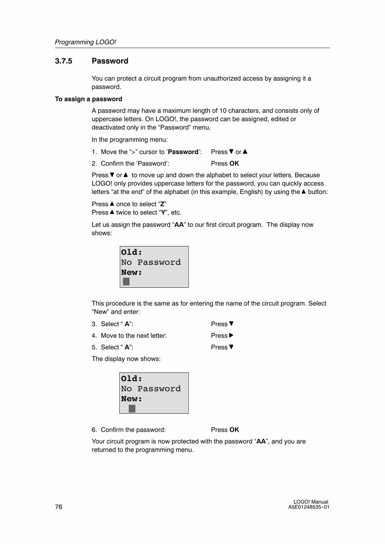
Programming LOGO!
76LOGO! Manual
A5E01248535--01
3.7.5 Password
You can protect a circuit program from unauthorized access by assigning it apassword.
To assign a password
A password may have a maximum length of 10 characters, and consists only ofuppercase letters. On LOGO!, the password can be assigned, edited ordeactivated only in the “Password” menu.
In the programming menu:
1. Move the “>” cursor to ’Password’: Press or
2. Confirm the ’Password’: Press OK
Press or to move up and down the alphabet to select your letters. BecauseLOGO! only provides uppercase letters for the password, you can quickly accessletters “at the end“ of the alphabet (in this example, English) by using the button:
Press once to select “Z”Press twice to select “Y”, etc.
Let us assign the password “AA” to our first circuit program. The display nowshows:
Old:No PasswordNew:
This procedure is the same as for entering the name of the circuit program. Select“New” and enter:
3. Select “ A”: Press
4. Move to the next letter: Press
5. Select “ A”: Press
The display now shows:
Old:No PasswordNew:
6. Confirm the password: Press OK
Your circuit program is now protected with the password “AA”, and you arereturned to the programming menu.

Programming LOGO!
77LOGO! ManualA5E01248535--01
Note
You can cancel the input of a new password with ESC. In this case, LOGO! returnsto the programming menu without saving the password.
You can also set your password using LOGO!Soft Comfort. You cannot edit apassword-protected circuit program on LOGO! or upload it to LOGO!Soft Comfortunless you enter the correct password.
To allow you to create and edit a circuit program for a protected module (Card),you first need to assign a password to this new program (see Chapter 6.1).
Changing the password
You need to know the current password in order to change it.
In the programming menu:
1. Move the ’>’ cursor to ’Password’: Press or
2. Confirm the ’Password’: Press OK
Select “Old” and enter your old password (in our case: ’AA’) by repeating steps 3through 6 as described earlier.
The display now shows:
Old:AANew:
Now you can select “New” to enter the new password, e.g. “ZZ”:
3. Select “Z”: Press
4. Move to the next letter: Press
5. Select “Z”: Press
The display now shows:
Old:AANew:ZZ
6. Confirm your new password: Press OK
Your new password “ZZ” is now set, and you are returned to the programmingmenu.
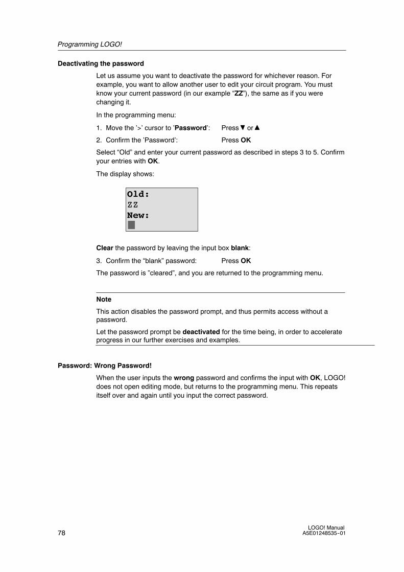
Programming LOGO!
78LOGO! Manual
A5E01248535--01
Deactivating the password
Let us assume you want to deactivate the password for whichever reason. Forexample, you want to allow another user to edit your circuit program. You mustknow your current password (in our example “ZZ”), the same as if you werechanging it.
In the programming menu:
1. Move the ’>’ cursor to ’Password’: Press or
2. Confirm the ’Password’: Press OK
Select “Old” and enter your current password as described in steps 3 to 5. Confirmyour entries with OK.
The display shows:
Old:ZZNew:
Clear the password by leaving the input box blank:
3. Confirm the “blank” password: Press OK
The password is ”cleared”, and you are returned to the programming menu.
Note
This action disables the password prompt, and thus permits access without apassword.
Let the password prompt be deactivated for the time being, in order to accelerateprogress in our further exercises and examples.
Password: Wrong Password!
When the user inputs the wrong password and confirms the input with OK, LOGO!does not open editing mode, but returns to the programming menu. This repeatsitself over and again until you input the correct password.

Programming LOGO!
79LOGO! ManualA5E01248535--01
3.7.6 Switching LOGO! to RUN mode
In the main menu, select RUN to start LOGO!.
1. Return to the main menu: Press ESC
2. Move the ’>’ cursor to ’Start’: Press or
3. Confirm ’Start’: Press OK
LOGO! runs the circuit program and shows the following display:
Display field of LOGO! in RUN mode
Start screen: Date and current time-of-day (onlyfor versions with real-time clock). This elementflashes if the date and time are not set.Or: Start screen digital inputs (see Chapter 5.2.5)
2008-05-26Mo 09:00
Press
Inputs I1 to I9I:0.. 1234567891..01234567892..01234
Inputs I20 to I24
Inputs I10 to I19
Press
Q:0.. 1234567891..0123456
Outputs Q1 to Q9
Outputs Q10 to Q16
Press
AI:1: 000002: 010003: 00253
Analog inputs AI1 to AI3
Press
AI:4: 000105: 000006: 00005
Analog inputs AI4 to AI6
Press

Programming LOGO!
80LOGO! Manual
A5E01248535--01
Press
Flags M1 to M9M:0.. 1234567891..01234567892..01234567
Flags M20 to M27
Flags M10 to M19
Press
ESC+C4 cursor keys for manual interventionin the circuit program (ESC+key)
AI:7: 000008: 00000
Analog inputs AI7 to AI8
Press
AQ:1: 000002: 01000
Analog outputs AQ1 to AQ2
What is meant by: ”LOGO! is in RUN”?
In RUN mode, LOGO! executes the circuit program. To do so, LOGO! first readsthe status at the inputs, determines the status of the outputs by means of the userprogram, and switches these on or off according to your settings.
This is how LOGO! indicates the I/O status:
Q:0.. 1234567891..0123456
Input/output status is ’1’:invertedInput/output status is ’0’: notinverted
I:
In this example, only the inputs I1, I15, Q8 and Q12 are set“high“.
0.. 1234567891..01234567892..01234
Status indication on the display
I:0.. 1234567891..01234567892..01234
L1
N
S1 S2=1When switch S1 is closed, the statusat input I1 is hi.
LOGO! computes the output statesby means of the circuit program.
Output Q1 = ’1’, in this case.
When Q1 = ’1’, LOGO! sets relayQ1, and the load connected to Q1 issupplied with voltage.
I1 I2
Q1
Let us examine thisusing our example:
Q:0.. 1234567891..0123456

Programming LOGO!
81LOGO! ManualA5E01248535--01
3.7.7 Second circuit program
Up to this point, you have successfully created your first circuit and assigned it aname and, if desired, a password. In this section we will show you how to modifyexisting circuit programs and how to use the special functions.
Using this second circuit program, we will show you how to:
• Add a block to an existing circuit program.
• Select a block for a special function.
• Assign parameters.
Modifying circuits
We shall use the first circuit program as a basis for the second, with some slightmodifications.
First of all take a look at the circuit diagram for the second circuit program:
L1
N
S1 S2
You already know the first part of thecircuit. S1 and S2 switch a relay, whichis to be used to switch on the load E1,and to switch off the load with a delayof 12 minutes.
K1
K1 E1
This is the circuit program layout in LOGO!:
≥1
Q1
I1I2x x
Par
This is thenew block
You can see the OR block and the output relay Q1 we have already used in the firstcircuit program. The only difference is the new off-delay block.
Editing the circuit program
Switch LOGO! to programming mode.
As a reminder:
1. Switch LOGO! to programming mode(in RUN: Press ESC to enter the parameter assignment mode. Select the ’Stop’command, confirm with OK, then move the ’>’ cursor to ’Yes’, and once againconfirm with OK). See Page 64.
2. On the main menu, select ”Program”
3. On the Programming menu, select “Edit”, confirm with OK. Next, select ”EditPrg” and confirm with OK.If required, enter your password at the prompt and confirm with OK.
You can now modify the current circuit program.

Programming LOGO!
82LOGO! Manual
A5E01248535--01
Adding a block to a circuit program
Move the cursor to the B in B1 (B1 is the number of the OR block):
Q1B1
To move the cursor:Press
We now insert the new block at this position.Confirm with OK.
Q1BN
LOGO! shows you the BN list
Press B to select the SF list:
Q1SF
The SF list contains the specialfunction blocks.
Press OK.
The block of the first special function is shown:
TrgPar Q1
When you select a special or basic function block,LOGO! shows you the relevant function block. Thesolid square cursor is positioned on the block.PressB orY to select the required block.
Select your block (off-delay, see the next figure), and then press OK:
R
The added block is assigned the block numberB2. The cursor is positioned at the top input ofthe added block.B1
ParQ1
B2
Before you press’OK’, this shows theentry Trg

Programming LOGO!
83LOGO! ManualA5E01248535--01
The B1 block previously connected to Q1 is automatically connected to theuppermost input of the new block. Note that you can only interconnect digital inputswith digital outputs or analog inputs with analog outputs. The ’old’ block willotherwise be lost.
The off-delay block has three inputs. At the top is the trigger input (Trg) you use tostart the off-delay time. In our example, the OR block B1 triggers the off-delay. Youreset the time and the output with a signal at the reset input. Set the off-delay timeat parameter T of the input Par.
In our example we do not use the reset input of the off-delay function, and weidentify it with an ’x’ connector.
xB1
ParQ1
B2This is what the display should now show
Assigning block parameters
Now you set the off-delay time T:
1. Move the cursor to Par, if it not already at this position: Press or
2. Switch to editing mode: Press OK
LOGO! shows the parameters in the parameter assignment window:
“+” means: The parameter isshown and can be modified in theparameter assignment mode.“R” means: Retentivity is enabledfor this block.
T: The blockparameter B2 is atime function
B2 +RT =00:00s
Time value Timebase
To change the time value:
• Press and to position the cursor.
• Press and to modify the value at the relevant position.
• Confirm your entries with OK.

Programming LOGO!
84LOGO! Manual
A5E01248535--01
Setting the time
Set the time T = 12:00 minutes:
1. Move the cursor to the first digit: Press or
2. Select the digit ’1’: Press or
3. Shift the cursor to the second digit: Press or
4. Select digit ’2’: Press or
5. Move the cursor to the unit: Press or
6. Select the timebase ’m’ (for minutes): Press or
Showing/hiding parameters -- the parameter protection mode
If you want to show/hide the parameter and allow/prevent its modification inparameter assignment mode:
1. Move the cursor to the protection mode: Press or
2. Select the protection mode: Press or
The display should now show:
Protection mode +: Thevalue of the time T can bemodified in parameter as-signment mode
Protectionmode -- : Thevalue of the time T is hid-den in parameter assign-ment mode
T=12:00mB2 +R
T=12:00mB2 -R
or
3. Confirm your entries with: OK
Enabling/disabling retentivity
To decide whether you want to retain your current data after a power failure or not:
1. Move the cursor to the retentivity setting: Press or
2. Select the retentivity setting: Press or
The display now shows:
or
Retentivity R: Currentdata is retained
Retentivity /: Currentdata is not retained
T=12:00mB2 -/
T=12:00mB2 -R
3. Confirm your entries with OK

Programming LOGO!
85LOGO! ManualA5E01248535--01
Note
For further information on the protection mode, refer to Chapter 4.3.5.
For further information on retentivity, refer to Chapter 4.3.4
You can modify the protection mode and retentivity setting only in programmingmode. This is not possible in parameter assignment mode.
In this manual, the protection mode (”+” or “--”) and retentivity (”R” or “/”) settingsare only shown in the displays where these can actually be changed.
Verification of the circuit program
This program branch for Q1 is now completed. LOGO! shows you the output Q1.You can once again view the circuit program on the display. Use the keys tobrowse the circuit program; that is, press or to move from block to block, andto move between the inputs at a block.
Closing the programming mode
Although you were shown how to exit the programming mode when you createdyour first circuit program,here is a reminder:
1. Return to the programming menu: Press ESC
2. Return to the main menu: Press ESC
3. Move the ’>’ cursor to ’Start’: Press or
4. Confirm ’Start’: Press OK
LOGO! is back in RUN mode:
You can press orto scroll the pages and to monitor the I/O states.
2008-05-26Mo 09:30
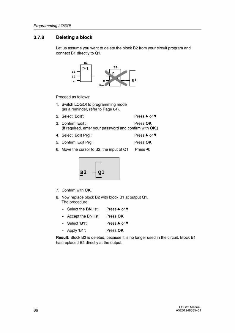
Programming LOGO!
86LOGO! Manual
A5E01248535--01
3.7.8 Deleting a block
Let us assume you want to delete the block B2 from your circuit program andconnect B1 directly to Q1.
Q1
I1
I2
x x
Par
B1
B2
Proceed as follows:
1. Switch LOGO! to programming mode(as a reminder, refer to Page 64).
2. Select ’Edit’: Press or
3. Confirm ’Edit’: Press OK(If required, enter your password and confirm with OK.)
4. Select ’Edit Prg’: Press or
5. Confirm ’Edit Prg’: Press OK
6. Move the cursor to B2, the input of Q1 Press :
B2 Q1
7. Confirm with OK.
8. Now replace block B2 with block B1 at output Q1.The procedure:
-- Select the BN list: Press or
-- Accept the BN list: Press OK
-- Select ’B1’: Press or
-- Apply ’B1’: Press OK
Result: Block B2 is deleted, because it is no longer used in the circuit. Block B1has replaced B2 directly at the output.

Programming LOGO!
87LOGO! ManualA5E01248535--01
3.7.9 Deleting block groups
Let us assume you want to delete the blocks B1 and B2 from the following circuitprogram (corresponds with the circuit program in Chapter 3.7.7).
Q1
I1
I2
x x
Par
B1
B2
Proceed as follows:
1. Switch LOGO! to programming mode(as a reminder, refer to page 64).
2. To select ’Edit’: Press or
3. To confirm ’Edit’: Press OK(If required, enter your password and confirm with OK.)
4. To select ’Edit Prg’: Press or
5. To confirm ’Edit Prg’: Press OK
6. To move the cursor to the input of Q1; that is, to B2,press :
B2 Q1
7. Confirm with OK.
8. Now set the connector ’x’ at output Q1 instead of block B2. To do so:
-- Select the Co list: Press or
-- Accept the Co list: Press OK
-- Select ’x’: Press or
-- Apply ’x’: Press OK
Result: Block B2 is deleted, because it is no longer used in the circuit. Thisincludes all blocks connected to B2. In this example, block B1 also.

Programming LOGO!
88LOGO! Manual
A5E01248535--01
3.7.10 Correcting programming errors
Programming errors can be corrected easily in LOGO! :
• Provided editing mode is not yet closed, you can revert by one step by pressingESC.
• If you have already configured all inputs, simply reconfigure the faulty input:
1. Move the cursor to the faulty position
2. Change to editing mode. Press OK
3. Enter the correct input circuit
You can only replace a block with a block that has exactly the same number ofinputs. However, you can delete the old block and then insert a new one. You canchoose any new block.
3.7.11 Selecting analog output values for RUN/STOP transition
You can select the analog values that are output at the two analog outputs whenLOGO! changes from RUN mode to STOP mode.
In the programming menu:
1. Move the “>” cursor to ’Edit..’: Press or
2. Select ’Edit’: Press OK
3. Move the “>” cursor to ’AQ’: Press or
4. Selectt ’AQ’: Press OK
5. Move the “>” cursor to ’AQ in Stop’: Press or
6. Select ’AQ in Stop’: Press OK
LOGO! shows the following display:
>DefinedLast
AQ in StopLast
The first two rows show your choices. The bottom row shows the current setting forthe analog output channels. The default setting is ’Last’.
You can select either ’Defined’ or ’Last’. ’Last’ means that the analog output valuesare held at their last value and ’Defined’ means that the analog output values areset to specific values. When LOGO! changes from RUN mode to STOP mode, thevalues of the analog outputs change as well, depending on the setting.
7. Select the desired output setting: Press or .
8. Confirm your entry: Press OK

Programming LOGO!
89LOGO! ManualA5E01248535--01
Defining a specific analog output value
To output a specific analog value at the two analog outputs:
9. Move the ’>’ cursor to ’Defined’: Press or
10.Confirm ’Defined’: Press OK
The display shows:
AQ1: 00.00AQ2: 00.00
11.Enter a specific output value for each of the two analog outputs.
12.To confirm your entry: Press OK
3.7.12 Defining the type of analog outputs
Analog outputs can be either 0..10V/0..20mA, which is the default, or 4..20mA.
To define the type of analog outputs, follow these steps starting from theprogramming menu:
1. Move the “>” cursor to ’Edit..’: Press or
2. Select ’Edit’: Press OK
3. Move the “>” cursor to ’AQ’: Press or
4. Select ’AQ’: Press OK
5. Move the “>” cursor to ’AQ type’: Press or
6. Select ’AQ type’: Press OK
LOGO! shows the following display, for example:
AQ1:defaultAQ2:4..20mA
The defined type for each analog channel is shown. To change the type, continueas follows
7. Move to the AQthat you want to change. Press or
8. Select either default (0..10V/0..20mA)or 4..20mA. Press or
9. Confirm your selection. Press OK

Programming LOGO!
90LOGO! Manual
A5E01248535--01
3.7.13 Deleting the circuit program and password
To delete a circuit program and the password if one is defined:
1. Switch the LOGO! to programming mode (main menu).
LOGO! opens the main menu>Program..Card..Setup..Start
2. On the main menu, press or to move the ’>’ cursor to ’Program’. Press OK.
>Edit..Clear PrgPasswordMsg Config
LOGO! changes to the programming menu
3. On the programming menu, move the ’>’ cursor to ’Clear Prg’:Press or
4. Confirm ’Clear Prg’: Press OK
Clear Prg>NoYes

Programming LOGO!
91LOGO! ManualA5E01248535--01
To cancel deletion of the circuit program, leave the ’>’ cursor at ’No’ and press OK.
If you are sure that you want to delete the circuit program from memory:
5. Move the ’>’ cursor to ’Yes’: Press or
6. Press OK.
Password?ZZ
To prevent unintentional deletion ofyour circuit program, you areprompted to enter your password(provided you have assigned one).
7. Enter your password.
8. Press OK. The circuit program and the password are deleted.
Note
Although you may have forgotten your password, you can still delete the circuitprogram and password by entering the wrong password three times.
3.7.14 Summertime/wintertime conversion
You can enable or disable automatic summertime/wintertime conversion
• in parameter assignment mode by calling the “Set..” menu command
• in programming mode by calling the “Setup” menu command.
To enable/disable automatic S/W Time conversion in programming mode:
1. Switch LOGO! to programming mode.
2. You are now in the main menu and want to select the ’Setup’ menu command:Press or
3. Confirm ’Setup’: Press OK
4. Move the ’>’ cursor to ’Clock’: Press or
5. Confirm ’Clock’: Press OK
6. Move the ’>’ cursor to ’S/W Time’: Press or
7. Confirm ’S/W Time’: Press OK
LOGO! shows the following display:
>OnOff
S/W Time:Off
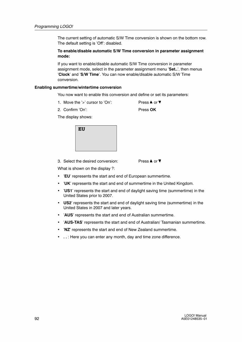
Programming LOGO!
92LOGO! Manual
A5E01248535--01
The current setting of automatic S/W Time conversion is shown on the bottom row.The default setting is ’Off’: disabled.
To enable/disable automatic S/W Time conversion in parameter assignmentmode:
If you want to enable/disable automatic S/W Time conversion in parameterassignment mode, select in the parameter assignment menu ’Set..’, then menus’Clock’ and ’S/W Time’. You can now enable/disable automatic S/W Timeconversion.
Enabling summertime/wintertime conversion
You now want to enable this conversion and define or set its parameters:
1. Move the ’>’ cursor to ’On’: Press or
2. Confirm ’On’: Press OK
The display shows:
EU
3. Select the desired conversion: Press or
What is shown on the display ?:
• ’EU’ represents the start and end of European summertime.
• ’UK’ represents the start and end of summertime in the United Kingdom.
• ’US1’ represents the start and end of daylight saving time (summertime) in theUnited States prior to 2007.
• US2’ represents the start and end of daylight saving time (summertime) in theUnited States in 2007 and later years.
• ’AUS’ represents the start and end of Australian summertime.
• ’AUS-TAS’ represents the start and end of Australian/ Tasmanian summertime.
• ’NZ’ represents the start and end of New Zealand summertime.
• . . : Here you can enter any month, day and time zone difference.

Programming LOGO!
93LOGO! ManualA5E01248535--01
The table below lists the preset conversions:
Start of summertime End of summertime Time zonedifference ∆
EU Last Sunday in March:02:00---->03:00
Last Sunday in October:03:00---->02:00
60 Min.
UK Last Sunday in March:01:00---->02:00
Last Sunday in October:02:00---->01:00
60 Min.
US1 First Sunday in April:02:00---->03:00
Last Sunday in October:02:00---->01:00
60 Min.
US2 Second Sunday in April:02:00---->03:00
First Sunday in November:02:00---->01:00
60 Min.
AUS Last Sunday in October:02:00---->03:00
Last Sunday in March:03:00---->02:00
60 Min.
AUS-TAS
First Sunday in October:02:00---->03:00
Last Sunday in March:03:00---->02:00
60 Min.
NZ First Sunday in October:02:00---->03:00
Third Sunday in March:03:00---->02:00
60 Min.
.. Customized month andday; 02:00---->02:00 +Time zone difference
Customized month andday; Time zone difference:03:00---->03:00 -- Timezone difference
User-defined(resolution inminutes)
Note
You can specify a time zone difference ∆ between 0 and 180 minutes.
Let us assume you want to enable European summertime/wintertime conversion:
4. Move the ’>’ cursor to ’EU’: Press or
5. Confirm ’EU’: Press OK
LOGO! shows the following display:
>OnOff
S/W Time:On→EU
LOGO! indicates that European S/W Time conversion is enabled.

Programming LOGO!
94LOGO! Manual
A5E01248535--01
User-defined parameters
If none of the parameters/conversions apply to your country, you can customizethese under menu item ’. .’. To do so:
1. Confirm ’On’ once again: Press OK
2. Move the ’>’ cursor to ’. .’: Press or
3. Confirm the menu item ’. .’ : PressOK
The display shows:
MM-DD+ : 01-01- : 01-01∆ =000min
Month (MM) and Day (DD)
Start of summertime
End of summertime
The desired time zone difference in[min]
0
Cursor / solid square
Let us assume you want to configure the following parameters: Start ofsummertime = 31st March, end of summertime = 1st November, time difference of120 minutes.
This is how you can enter your data:
• Press or to move the solid square/cursor.
• Press and to change the value at the cursor position.
The display shows:
MM-DD+ : 03-31- : 11-01∆ =120min
31. March
1. November
Time difference of 120 min
• Confirm all your entries with OK.
You have now customized the summertime/wintertime conversion. The LOGO!display now shows:
>OnOff
S/W Time:On→..
LOGO! indicates that summertime/wintertime conversion is enabled, and thatuser-defined parameters ( ’..’ ) have been set.

Programming LOGO!
95LOGO! ManualA5E01248535--01
Note
To disable summertime/wintertime conversion in this menu, you merely confirm’Off’ with OK.
Note
Summertime/wintertime conversion only functions when LOGO! is operating (inRUN or STOP status). It does not function when LOGO! is in buffered operation(see Chapter 4.3.3).
3.7.15 Synchronization
Time synchronization between LOGO! and a connected communication moduleEIB/KNX (version 0AA1 upwards!) can be enabled/disabled
• in parameter assignment mode by means of the set menu (“Clock” menu item)
• in programming mode by means of the setup menu (“Clock” menu item).
When synchronization is enabled, LOGO! can receive the time-of-day from acommunication module EIB/KNX (version 0AA1 upwards).
Whether synchronization is enabled or disabled, the time-of-day is always sent tothe expansion modules at power-up, every hour (STOP mode or RUN mode), andwhen the TOD is changed (after a ’Set Clock’ is executed or after asummertime/wintertime conversion).
Note
When using a LOGO! basic module with digital or analog expansion modules, butwithout communication module EIB/KNX (version 0AA1 upwards), timesynchronization must not be activated! You must check whether timesynchronization is deactivated (’Sync’ must be set to ’Off’).
To enable/disable synchronization in programming mode:
1. Switch LOGO! to programming mode.
2. You are now in the main menu, and want to select ’Setup’: Press or
3. Confirm ’Setup’: Press OK
4. Move the ’>’ cursor to ’Clock’: Press or
5. Confirm ’Clock’: Press OK
6. Move the ’>’ cursor to ’Sync’: Press or
7. Apply ’Sync’: Press OK

Programming LOGO!
96LOGO! Manual
A5E01248535--01
LOGO! shows the following display:
>OnOff
Sync:Off
The current setting of the automatic synchronization function is displayed on thebottom row. The default setting is ’Off’; that is, disabled.
To enable/disable synchronization in parameter assignment mode:
If you want to enable/disable automatic synchronization in parameter assignmentmode, select in the parameter assignment menu ’Set..’, then menus ’Clock’ and’Sync’. You can now enable/disable automatic synchronization.
Enabling synchronization
You want to enable synchronization:
1. Move the ’>’ cursor to ’On’: Press or
2. Confirm ’On’: Press OK
LOGO! shows the following display:
>OnOff
Sync:On
3.8 Memory space and circuit program size
The size of a circuit program in LOGO! is limited by the memory space (memoryused by the blocks).
Memory areas
• Program memory:LOGO! allows only a limited number of blocks in your circuit program.The second limitation is based on the maximum number of bytes a circuitprogram may contain. The total number of bytes used can be determined byadding up the number of bytes used for the relevant function blocks.
• Retentive memory (Rem):In this area, LOGO! stores values which need to be retentive, for example, thehours counter value. Blocks with optional retentivity use this memory area only ifthis function is actually enabled.

Programming LOGO!
97LOGO! ManualA5E01248535--01
Resources available in LOGO!
A circuit program in LOGO! can occupy the following maximum resources:
Bytes Blocks REM
3800 200 250
LOGO! monitors memory utilization, and offers only those functions from the listsfor which it can actually provide sufficient memory space.
Memory requirements
The table below shows an overview of the memory requirements for the basic andspecial function blocks:
Function Programmemory
Remmemory*
Basic functions
AND 12 --
AND with edge evaluation 12 --
NAND (not AND) 12 --
NAND with edge evaluation 12 --
OR 12 --
NOR (not OR) 12 --
XOR (exclusive OR) 8 --
NOT (Negation) 4 --
Special functions
Timers
On-delay 8 3
Off-delay 12 3
On-/Off-delay 12 3
Retentive on-delay 12 3
Wiping relay (pulse output) 8 3
Edge triggered wiping relay 16 4
Asynchronous pulse generator 12 3
Random generator 12 --
Stairway lighting switch 12 3
Multiple function switch 16 3
Weekly timer 20 --
Yearly timer 12 --
Counters
Up/down counter 28 5
Hours counter 28 9
Threshold trigger 16 --

Programming LOGO!
98LOGO! Manual
A5E01248535--01
Function Remmemory*
Programmemory
Analog
Analog threshold trigger 16 --
Analog differential trigger 16 --
Analog comparator 24 --
Analog value monitoring 20 --
Analog amplifier 12 --
Pulse Width Modulator (PWM) 24 --
Analog math 20 --
Analog math error detection 12 1
Analog multiplexer 20 --
Analog ramp 36 --
PI controller 40 2
Others
Latching relay 8 1
Pulse relay 12 1
Message texts 8 --
Softkey 8 2
Shift register 12 1
*: Bytes in the Rem memory area if retentivity is enabled.
Utilization of memory areas
The system indicates that there is insufficient memory space by not allowing you toadd a further block to your circuit program. LOGO! offers you only the blocks forwhich it can provide sufficient memory space. If LOGO! memory space isinsufficient to hold any further blocks you select from a block list, the system willdeny access to this list.
If memory space is fully occupied, optimize your circuit program or install a secondLOGO!

Programming LOGO!
99LOGO! ManualA5E01248535--01
Calculating memory requirements
When calculating the memory requirements of a circuit, you must always take intoaccount all individual areas of memory.
Example:
Q1xI2
B1B2
B3
x
B4
--20
No 1No 2No 3
I1Par
B5B6
Par Q2
I3I4x
REMBytes
--12REMBytes
The sample circuit program contains:
Block no. Function Memory area
Bytes Blocks REM
B1 OR 12 1 --
B2 AND 12 1 --
B3 Weekly timer 20 1 --
B4 On-delay* 8 1 3
B5 Stairway lighting switch 12 1 0
B6 AND 12 1 --
Resources used by the circuit program 76 6 3
Memory space limits in LOGO! 3800 200 250
Still available in LOGO! 3724 194 247
*: Configured with retentivity.
This means that this circuit program fits in LOGO!.

Programming LOGO!
100LOGO! Manual
A5E01248535--01
Indication of available memory space
LOGO! shows you the amount of free memory space.
Proceed as follows:
1. Switch LOGO! to programming mode(as a reminder, refer to page 64).
2. Select ’Edit’: Press or
3. Accept ’Edit’: Press OK
4. Select ’Memory?’: Press or
5. Accept ’Memory?’: Press OK
The display now shows:
Free Memory:Byte =3724Block= 194Rem = 247

101LOGO! ManualA5E01248535--01
LOGO! functions
Organization
LOGO! provides you with various elements in programming mode. In order tomaintain the overview, we have organized the elements in ’Lists’. These lists are:
• ↓Co: Connector list (Connector)(see Chapter 4.1)
• ↓GF: List of the basic functions AND, OR, ...(refer to Chapter 4.2)
• ↓SF: List of the special functions(refer to Chapter 4.4)
• ↓BN: List of reusable blocks configured in the circuit program
List contents
All lists show the elements available in LOGO! Usually, this includes all connectors,basic functions, and special functions. The ↓BN list shows all the blocks that youhave created in LOGO!.
If not all is shown
LOGO! does not show all elements if:
• No further blocks may be added.
This is either an indication of insufficient memory space or that the maximumnumber of blocks has been reached.
• A specific block’s memory space requirement would exceed the space availablein LOGO!
See Chapter 3.8.
4
LOGO! functions
102LOGO! Manual
A5E01248535--01
4.1 Constants and connectors -- Co
Constants and connectors (= Co) represent inputs, outputs, flags and constantvoltage levels (constants).
Inputs:
1) Digital inputs
Digital inputs are identified with an I. The number of the digital inputs (I1, I2, ...)corresponds to the number of the input connectors of the LOGO! Basic and of theconnected digital modules, in the order of their installation. The fast digital inputsI3, I4, I5, and I6 of the LOGO! versions LOGO! 24, LOGO! 24o, LOGO! 12/24RCand LOGO! 12/24RCo can be used as fast counters.
2) Analog inputs
The LOGO! versions LOGO! 24, LOGO! 24o, LOGO! 12/24RC andLOGO! 12/24RCo are equipped with the inputs I1, I2, I7 and I8, which can also beprogrammed for use as AI3, AI4, AI1 and AI2 inputs. As described in section 5.2.4,you can configure these modules to use either two analog inputs (AI1 and AI2), orall four. Signals at the I1, I2, I7 and I8 inputs are interpreted as digital values, andthose at the AI3, AI4, AI1 and AI2 inputs are interpreted as analog values. Notethat AI3 corresponds to I1 and AI4 corresponds to I2. This numbering preservesthe previous correspondence of AI1 to I7 and AI2 to I8 that was available with the0BA5 series.The inputs of a connected analog module are numbered according tothe already existing analog inputs. See section 2.1.1 for example setups. Inprogramming mode, when you select the input signal of a special function thattakes an analog input, LOGO! offers the analog inputs AI1...AI8, analog flagsAM1...AM6, analog outputs AQ1 and AQ2, and the block numbers of functions withanalog outputs.
Outputs:
1) Digital outputs
Digital outputs are identified by the character Q. The output numbers (Q1, Q2, ...Q16) correspond with the numbers of the output connectors at the LOGO! Basicand with those of the expansion modules, in their order of installation. See thefollowing figure.
There are also 16 blank outputs available. These are identified with an x andcannot be reused in a circuit program (in contrast to flags, for example). The listshows all programmed blank outputs, and one blank output which is not yetconfigured. A blank output, for example, is useful for the special function ”Messagetexts” (see Chapter 4.4.23), if only the message text is of significance to a circuitprogram.

LOGO! functions
103LOGO! ManualA5E01248535--01
2) Analog outputs
Analog outputs are identified by the letters AQ. Two analog outputs are available,namely AQ1 and AQ2. An analog output can only be connected with the analoginput of a function, an analog flag AM or an analog output connector.
The following figure shows an example LOGO! configuration and the numbering ofthe inputs and outputs for the circuit program.
L+ M I13I14I15 I16
Q11
Q9
Q12
Q10
RUN/STOP
L+ M
AI5
RUN/STOP
L+ M AI3 AI4 I3 I4 I5 I6
Q1 Q2 Q3 Q4
Inputs
Outputs
AI1 AI2 L+ M I9 I10I11I12
Q7
Q5
Q8
Q6
RUN/STOP
M3U3AI6M4U4
Analog inputs
1 2 1 2
1 2 1 21 2 1 2 1 2 1 2
1 2 1 2
1 2 1 2
PE
INPUT 2x (..10V/..20mA)
L+ M L+ M
RUN/STOP
M1 I1 I2V1+
L+ M
PE
OUTPUT 2x(0..10V/0/4..20mA)
M2V2+
Analog outputs
AQ1 AQ2
Flag blocks
Flag blocks are identified by the letters M or AM . These are virtual outputs, whichoutput the value of their inputs. LOGO! provides 27 digital flags M1 ... M27 and 6analog flags AM1 ... AM6.
Startup flag
Flag M8 is set in the first cycle of the user program and can thus be used in yourcircuit program as a startup flag. This signal is automatically reset after the circuitprogram has completed its first cycle.
The M8 flag can be used in all further cycles for setting, deletion and evaluationprocedures in the same way as other flags.
Backlight flags M25 and M26
The M25 flag controls the backlight of the LOGO! Display. The M26 flag controlsthe backlight of the LOGO! TD.
Note: The backlight lifetime of the LOGO! TD is 20,000 hours.
Message text character set flag M27
The M27 flag selects between the two character sets that LOGO! uses to displaymessage texts. State 0 corresponds to Character Set 1, and state 1 corresponds toCharacter Set 2. If M27=0 (low), only message texts configured for Character Set 1will display; If M27=1 (high), only message texts configured for Character Set 2 willdisplay. If you do not include M27 in the circuit program, message texts display inthe character set that you selected from either the Msg Config menu or fromLOGO!Soft Comfort.

LOGO! functions
104LOGO! Manual
A5E01248535--01
Note
The output of the flag always carries the signal of the previous program cycle. Thisvalue does not change within the same program cycle.
Shift register bits
LOGO! provides the shift register bits S1 to S8, which are assigned the read-onlyattribute in the circuit program. The content of shift register bits can only bemodified by means of the ”Shift register” special function (see Chapter 4.4.25).
Cursor keys
Up to four cursor keys are available to you, namely C Y, C ", C B and C A (”C” =”Cursor”). Cursor keys are programmed for the circuit program in the same way asother inputs. You can set the cursor keys in the corresponding display while thesystem is in RUN (see Chapter 3.7.6), and in an active message text (ESC + Key).Cursor keys can save switches and inputs, and allow operator control of the circuitprogram. Cursor key inputs from the LOGO! TD are identical to cursor key inputsfrom the LOGO! module.
LOGO! TD function keys
The LOGO! TD has four function keys that you can use in your circuit program. Youprogram these keys in the same way as other inputs. Like the cursor keys, you canpress these keys when LOGO! is in RUN mode to affect the behavior of the circuitprogram, and to save switches and inputs. They are identified as F1, F2, F3, andF4.
Levels
Voltage levels are designated hi and lo. A constant ”1” = hi or ”0” = lo status at theblock can be set by means of a permanent voltage level or constant value hi or lo.
Open connectors
Unused block connectors can be identified with an x.

LOGO! functions
105LOGO! ManualA5E01248535--01
4.2 Basic functions list -- GF
Basic functions represent simple logical elements of Boolean algebra.
You can invert the inputs of individual basic functions, that is, the circuit programinverts a logical ”1” at a relevant input to a logical ”0”; if ”0” is set at the input, theprogram sets a logical ”1”. A programming example is found in Chapter 3.7.3.
The GF list contains the basic function blocks you can use for your circuit program.The following basic functions are available:
View in the circuit diagram View in LOGO! Name of the basicfunction
Series circuitmake contact
AND
(see page 106)
AND with edge evaluation
(see page 106)
Parallel circuit withbreak contacts
NAND(not AND)
(see page 107)
NAND with edge evaluation
(see page 108)
Parallel circuit with makecontacts
OR
(see page 109)
Series circuit withbreak contacts
NOR(not OR)
(see page 109)
Doublechangeovercontact
XOR(exclusive OR)
(see page 110)
Breakcontact
NOT(negation, inverter)
(see page 111)

LOGO! functions
106LOGO! Manual
A5E01248535--01
4.2.1 AND
Circuit diagram of a seriescircuit with several makecontacts:
Symbol in LOGO!:
The output of the AND is only 1 if all inputs are 1, i.e. all contacts are closed.
At an unused block input (x): x = 1.
AND function logic table
1 2 3 4 Q0 0 0 0 00 0 0 1 00 0 1 0 00 0 1 1 00 1 0 0 00 1 0 1 00 1 1 0 00 1 1 1 01 0 0 0 01 0 0 1 01 0 1 0 01 0 1 1 01 1 0 0 01 1 0 1 01 1 1 0 01 1 1 1 1
4.2.2 AND with edge evaluation
Symbol in LOGO!:
The output of an edge triggered AND is only 1 if all inputs are 1 and if at least oneinput was low in the previous cycle.
At an unused block input (x): x = 1.
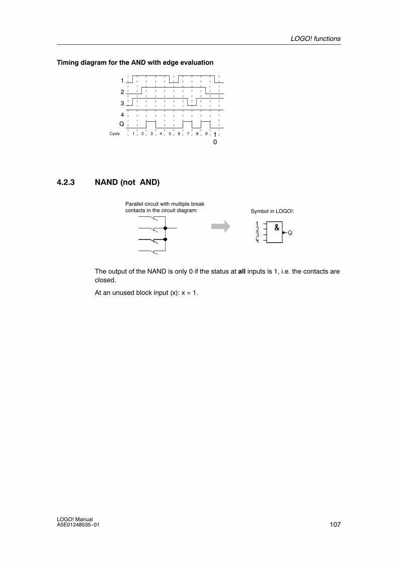
LOGO! functions
107LOGO! ManualA5E01248535--01
Timing diagram for the AND with edge evaluation
1
Cycle
3
Q
2
1 2 3 4 5 6 7 8 9 10
4
4.2.3 NAND (not AND)
Parallel circuit with multiple breakcontacts in the circuit diagram: Symbol in LOGO!:
The output of the NAND is only 0 if the status at all inputs is 1, i.e. the contacts areclosed.
At an unused block input (x): x = 1.
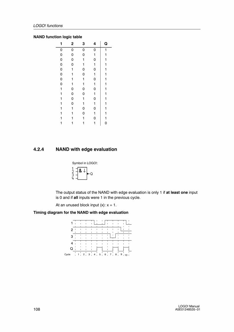
LOGO! functions
108LOGO! Manual
A5E01248535--01
NAND function logic table
1 2 3 4 Q0 0 0 0 10 0 0 1 10 0 1 0 10 0 1 1 10 1 0 0 10 1 0 1 10 1 1 0 10 1 1 1 11 0 0 0 11 0 0 1 11 0 1 0 11 0 1 1 11 1 0 0 11 1 0 1 11 1 1 0 11 1 1 1 0
4.2.4 NAND with edge evaluation
Symbol in LOGO!:
The output status of the NAND with edge evaluation is only 1 if at least one inputis 0 and if all inputs were 1 in the previous cycle.
At an unused block input (x): x = 1.
Timing diagram for the NAND with edge evaluation
1
Cycle
3
Q
2
1 2 3 4 5 6 7 8 9 10
4
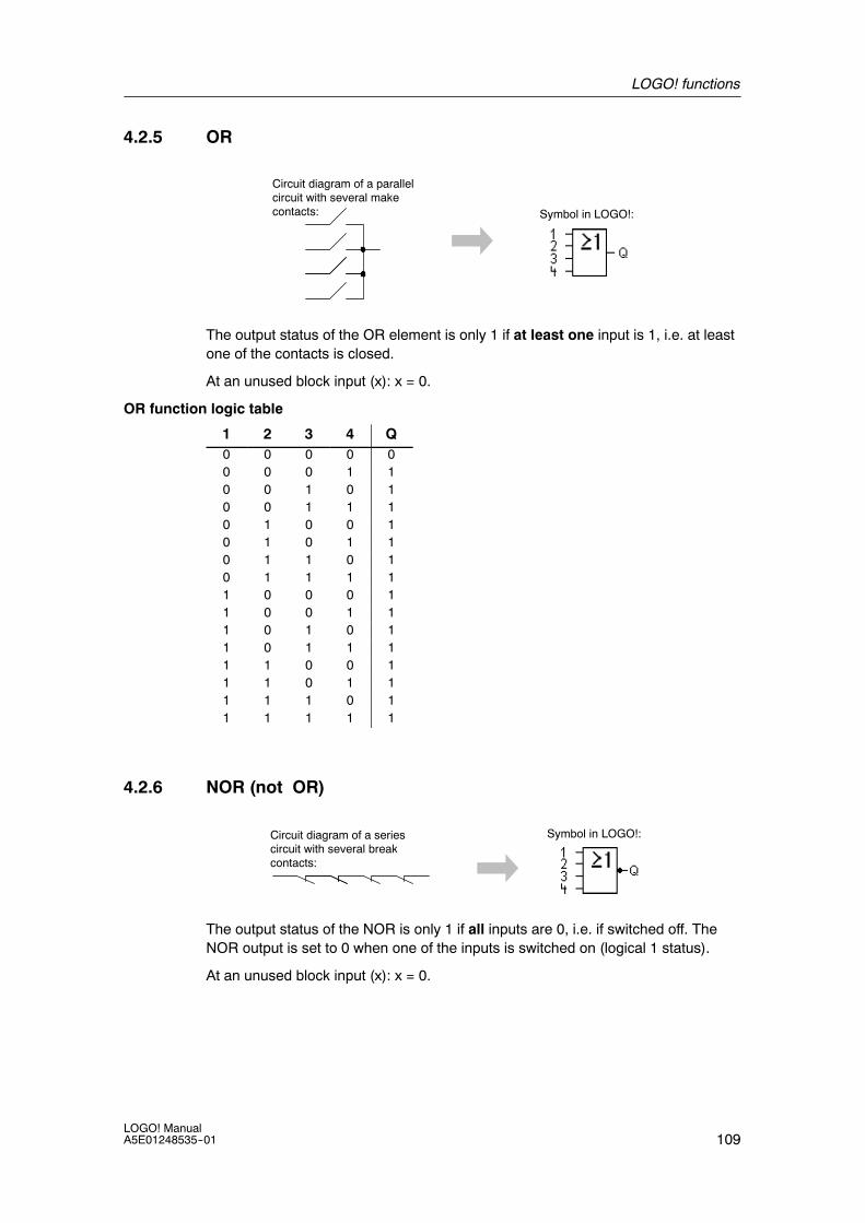
LOGO! functions
109LOGO! ManualA5E01248535--01
4.2.5 OR
Circuit diagram of a parallelcircuit with several makecontacts: Symbol in LOGO!:
The output status of the OR element is only 1 if at least one input is 1, i.e. at leastone of the contacts is closed.
At an unused block input (x): x = 0.
OR function logic table
1 2 3 4 Q0 0 0 0 00 0 0 1 10 0 1 0 10 0 1 1 10 1 0 0 10 1 0 1 10 1 1 0 10 1 1 1 11 0 0 0 11 0 0 1 11 0 1 0 11 0 1 1 11 1 0 0 11 1 0 1 11 1 1 0 11 1 1 1 1
4.2.6 NOR (not OR)
Circuit diagram of a seriescircuit with several breakcontacts:
Symbol in LOGO!:
The output status of the NOR is only 1 if all inputs are 0, i.e. if switched off. TheNOR output is set to 0 when one of the inputs is switched on (logical 1 status).
At an unused block input (x): x = 0.

LOGO! functions
110LOGO! Manual
A5E01248535--01
NOR function logic table
1 2 3 4 Q0 0 0 0 10 0 0 1 00 0 1 0 00 0 1 1 00 1 0 0 00 1 0 1 00 1 1 0 00 1 1 1 01 0 0 0 01 0 0 1 01 0 1 0 01 0 1 1 01 1 0 0 01 1 0 1 01 1 1 0 01 1 1 1 0
4.2.7 XOR (exclusive OR)
The XOR in a circuit diagram,shown as series circuit with 2changeover contacts:
Symbol in LOGO!:
The output status of the XOR is 1 if the inputs are not equivalent.
At an unused block input (x): x = 0.
XOR function logic table
1 2 Q
0 0 00 1 11 0 11 1 0

LOGO! functions
111LOGO! ManualA5E01248535--01
4.2.8 NOT (Negation, Inverter)
A break contact in the circuitdiagram:
Symbol in LOGO!:
The output status is 1 if the input is 0. The NOT block inverts the input status.
Advantage of the NOT block, for example: LOGO! does not require break contacts.You simply use a make contact and the NOT block to convert these into a breakcontact.
NOT function logic table
1 Q
0 1
1 0
4.3 Special functions
Because of their different input designation, you can see right away that there is adifference between the special functions and basic functions. SFs contain timerfunctions, retentive functions and various parameter assignment options, whichallow you to adapt the circuit program to suit your own requirements.
This section provides you with a brief overview of input designations and with someparticular background information on SFs. The SFs in particular are described inChapter 4.4.
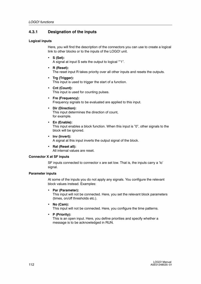
LOGO! functions
112LOGO! Manual
A5E01248535--01
4.3.1 Designation of the inputs
Logical inputs
Here, you will find the description of the connectors you can use to create a logicallink to other blocks or to the inputs of the LOGO! unit.
• S (Set):A signal at input S sets the output to logical “”1”.
• R (Reset):The reset input R takes priority over all other inputs and resets the outputs.
• Trg (Trigger):This input is used to trigger the start of a function.
• Cnt (Count):This input is used for counting pulses.
• Fre (Frequency):Frequency signals to be evaluated are applied to this input.
• Dir (Direction):This input determines the direction of count,for example.
• En (Enable):This input enables a block function. When this input is ”0”, other signals to theblock will be ignored.
• Inv (Invert):A signal at this input inverts the output signal of the block.
• Ral (Reset all):All internal values are reset.
Connector X at SF inputs
SF inputs connected to connector x are set low. That is, the inputs carry a ’lo’signal.
Parameter inputs
At some of the inputs you do not apply any signals. You configure the relevantblock values instead. Examples:
• Par (Parameter):This input will not be connected. Here, you set the relevant block parameters(times, on/off thresholds etc.).
• No (Cam):This input will not be connected. Here, you configure the time patterns.
• P (Priority):This is an open input. Here, you define priorities and specify whether amessage is to be acknowledged in RUN.

LOGO! functions
113LOGO! ManualA5E01248535--01
4.3.2 Time response
Parameter T
At some of the SFs it is possible to configure a time value T. When you preset thistime, note that your input values are based on the timebase set:
Timebase _ _ : _ _
s (seconds) seconds : 1/100 seconds
m (minutes) minutes : seconds
h (hours) hours : minutes
B1 +T =04:10h
Setting a time T of 250 minutes:
Unit in hours h:04:00 hours 240 minutes00:10 hours +10 minutes= 250 minutes
Note
Always specify a time T in≥ 0.02 s. The time T is not defined for T<0.02 s.
Accuracy of T
Because of slight tolerances in the characteristics of electronic components, the settime T may deviate. LOGO! has a maximum tolerance of 0.02 %.When 0.02 % of the time T is less than 0.02 seconds, the maximum deviation is0.02 seconds.
Example:
The maximum tolerance per hour (3600 seconds) is 0.02 %, which isproportional to 0.72 seconds.The maximum tolerance per minute (60 seconds) is 0.02 seconds.
Accuracy of the timer (weekly/yearly timer)
To prevent timing inaccuracy of the real-time clock in C versions caused by thisdeviation, the timer value is continuously compared with a high-precision timebaseand corrected. The resultant maximum timing inaccuracy is±5 s/day.

LOGO! functions
114LOGO! Manual
A5E01248535--01
4.3.3 Backup of the real-time clock
Because the internal real-time clock of a LOGO! is backed up, it continuesoperation after a power failure. The ambient temperature influences the backuptime. At an ambient temperature of 25˚C , the typical backup time is 80 hours.
If there is a power outage of a LOGO! for more than 80 hours, the internal clockresponds, dependent on the equipment series, as shown below:
• Equipment series 0BA0:On restarting, the clock is set to ”Sunday 00:00 1 January”. The time starts torun. Due to this, the system processes the time switches, which trigger actions ifnecessary.
• Equipment series 0BA1 and later:On restarting, the clock is set to ”Sunday 00:00 1 January”. The time is stoppedand flashes. LOGO! is back in the status that it was in before the power outage.In the RUN status, the system processes the counters that were parameterizedwith the time above. The clock is, however, still stopped.
• Equipment series 0BA6:If you are using the optional LOGO! Battery card, or combined LOGO!Memory/Battery card, LOGO! can retain the clock time for up to two years.These cards are available for equipment series 0BA6.
4.3.4 Retentivity
The switching states and counter values of SFs can be set retentive. This meansthat current data are retained after a power failure, and that the block resumesoperation at the break point. The timer is not reset, but resumes operation until thetime-to-go has expired, for example.
To enable this response, however, the relevant functions must be set retentive. Twooptions are available:
R: The data is retained./: Current data is not retained (default). See the example on Page 84.
SFs hours counter, weekly timer, yearly timer and PI controller are alwaysretentive.
4.3.5 Parameter protection
In the parameter protection settings, you can determine whether or not theparameters can be displayed and edited in LOGO! parameter assignment mode.Two options are available:
+: The parameter attribute permits read/write access in parameter assignmentmode (default).--: The parameter settings are read-/write-protected in parameter assignmentmode, and can be edited only in programming mode. See the example on Page 84.

LOGO! functions
115LOGO! ManualA5E01248535--01
4.3.6 Calculating the gain and offset of analog values
A sensor is connected to the analog input and converts a process variable into anelectrical signal. This value of signal lies within the typical range of this sensor.
LOGO! always converts the electrical signals at the analog input into digital valuesfrom 0 to 1000.
A voltage of 0 to 10 V at input AI is transformed internally into a range of valuesfrom 0 to 1000. An input voltage exceeding 10 V is shown as internal value 1000.
Because you cannot always process the range of values from 0 to 1000 aspredetermined by LOGO!, you can multiply the digital values by a gain factor andthen shift the zero of the range of values (offset). This allows you to output ananalog value to the LOGO! display, which is proportional to the actual processvariable.
Parameter Minimum Maximum
Input voltage (in V) 0 ≥ 10
Internal value 0 1000
Gain --10.00 +10.00
Offset --10000 +10000
Mathematical rule
Actual value Ax =(internal value at input Ax ¡ gain) + offset
Gain and offset calculation
The gain and offset is calculated based on the relevant high and low values of thefunction.
Example 1:
The available thermocouples have the following technical data: --30 to +70_C, 0 to10 V DC (i.e. 0 to 1000 in LOGO!).
Actual value = (internal value ¡ gain) + offset, thus
--30 = (0 ¡ A) + B, i.e. offset B = --30
+70 = (1000 ¡ A) --30, i.e. gain A = 0.1
Example 2:
A pressure sensor converts a pressure of 1000 mbar into a voltage of 0 V, and apressure of 5000 mbar into a voltage of 10 V.
Actual value = (internal value ¡ gain) + offset, thus
1000 = (0 ¡ A) + B, i.e. offset B = 1000
5000 = (1000 ¡ A) +1000, i.e. gain A = 4

LOGO! functions
116LOGO! Manual
A5E01248535--01
Example of analog values
Process variable Voltage (V) Internal value Gain Offset Value shown (Ax)
--30_ C0_ C
+70_ C
0310
03001000
0.10.10.1
--30--30--30
--30070
1000 mbar
3700 mbar
5000 mbar
0
6.75
10
0
675
1000
4
4
4
1000
1000
1000
1000
3700
5000
0510
05001000
0.010.010.01
000
0510
0510
05001000
111
000
05001000
0510
05001000
101010
000
0500010000
0510
05001000
0.010.010.01
555
51015
0510
05001000
111
500500500
50010001500
0510
05001000
111
--200--200--200
--200300800
010
01000
1010
--10000--10000
--100000
0.020.020.020.02
2222
0.010.1110
0000
00220
A sample application is found in the description of the ”Analog comparator” SF onPage 165.
For further information on analog inputs, refer to Chapter 4.1.

LOGO! functions
117LOGO! ManualA5E01248535--01
4.4 Special functions list -- SF
When you create your circuit program in LOGO!, you find the special functionblocks in the SF list.
You can invert the inputs of SFs individually, that is, the circuit program converts alogical ”1” at the input into a logical ”0”; a logical ”0” it converts into a logical ”1”. Anexample of the program code is found in Chapter 3.7.3.
The table also specifies whether the relevant function can be set retentive (Rem).The following SFs are available:
View in LOGO! Name of the special function Rem
Times
On-delay(see page 120)
REM
Off-delay
(see page 123)
REM
On-/Off-delay
(see Page 124)
REM
Retentive on-delay
(see page 126)
REM
Wiping relay (pulse output)
(see page 127)
REM
Edge triggered wiping relay
(see page 128)
REM
Asynchronous pulse generator
(see Page 130)
REM
Random generator(see page 132)
Stairway lighting switch
(see page 134)
REM

LOGO! functions
118LOGO! Manual
A5E01248535--01
View in LOGO! RemName of the special functionMultiple function switch
(see page 136)
REM
Weekly timer
(see Page 139)
Yearly timer(see Page 143)
Counter
Up/down counter
(see Page 149)
REM
Hours counter
(see page 152)
REM
Fre
Threshold trigger
(see Page 156)
Analog
Analog threshold trigger
(see page 159)
Analog differential trigger
(see page 162)
Analog comparator
(see Page 165)
Analog value monitoring
(see Page 170)
Analog amplifier
(see Page 173)

LOGO! functions
119LOGO! ManualA5E01248535--01
View in LOGO! RemName of the special functionAnalog multiplexer
(see Page 194)
Pulse Width Modulator (PWM)
(see Page 206)
Analog math
(see Page 209)
Analog ramp
(see Page 196)
A/MR
PVPar
AQ
PI controller
(see Page 200)
REM
Miscellaneous
Latching relay
(see Page 174)
REM
Pulse relay
(see Page 175)
REM
P
Message texts
(see Page 177)
EnPar Q
Softkey
(see Page 189)
REM
Shift register
(see Page 192)
REM
Analog math error detection
(see Page 212)

LOGO! functions
120LOGO! Manual
A5E01248535--01
4.4.1 On-delay
Short description
The output is only set after a configurable on-delay time has expired.
Symbol in LOGO! Wiring Description
Input Trg A signal at input Trg (Trigger) triggers theon-delay timer.
Parameter T represents the time after which the output isswitched on (0 to 1 transition of the outputsignal).
Retentivity:/ = no retentivityR = the status is retentive.
Output Q Q is switched on when the set time T hasexpired, provided Trg is still set.
Parameter T
Note the defaults for parameter T in Chapter 4.3.2.
The time for parameter T can also be preset based on the actual value of another,already-configured function. You can use the actual values of the followingfunctions:
• Analog comparator (actual value Ax -- Ay, see Chapter 4.4.18)
• Analog threshold trigger (actual value Ax, see Chapter 4.4.16)
• Analog amplifier (actual value Ax, see Chapter 4.4.20)
• Analog multiplexer (actual value AQ, see Chapter 4.4.26)
• Analog ramp (actual value AQ, see Chapter 4.4.27)
• Analog math (actual value AQ, see Chapter 4.4.30)
• PI controller (actual value AQ, see Chapter 4.4.28)
• Counter (actual value Cnt, see Chapter 4.4.13)
Select the required function by the block number. The timebase is adjustable.Please note the following listing:
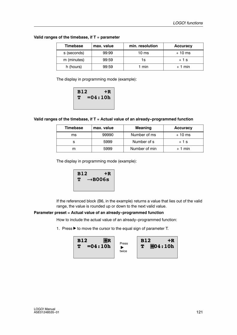
LOGO! functions
121LOGO! ManualA5E01248535--01
Valid ranges of the timebase, if T = parameter
Timebase max. value min. resolution Accuracy
s (seconds) 99:99 10 ms + 10 ms
m (minutes) 99:59 1s + 1 s
h (hours) 99:59 1 min + 1 min
The display in programming mode (example):
B12 +RT =04:10h
Valid ranges of the timebase, if T = Actual value of an already--programmed function
Timebase max. value Meaning Accuracy
ms 99990 Number of ms + 10 ms
s 5999 Number of s + 1 s
m 5999 Number of min + 1 min
The display in programming mode (example):
B12 +RT !B006s
If the referenced block (B6, in the example) returns a value that lies out of the validrange, the value is rounded up or down to the next valid value.
Parameter preset = Actual value of an already--programmed function
How to include the actual value of an already--programmed function:
1. Press to move the cursor to the equal sign of parameter T.
T =04:10hB12 +RT =04:10hB12 +R B12 +RB12 +R
Press"twice
T =04:10hT =04:10h

LOGO! functions
122LOGO! Manual
A5E01248535--01
2. Press to change the equal sign into an arrow. If it exists, the last referencedblock and its timebase is shown.
B12 +RT !B006s
3. Press to move the cursor to the ”B” of the shown block, and then press toselect the required block number.
4. Press to move the cursor to the block’s timebase and press to select therequired timebase.
B12 +RT !B006m
The view in parameter assignment mode (example):
T =04:10hT =04:10
Ta =02:00h
B12or
B12T !B006m
Ta =02:00hcurrenttime
Timing diagram
Trg
T TTa expires
Q
The bold section ofthe timing diagram isalso shown in theon-delay icon.
Functional description
The time Ta is triggered with a 0 to 1 transition at input Trg (Ta is the current LOGO!time).
If the status of input Trg is 1 at least for the duration of the configured time T, theoutput is set to 1 on expiration of this time (the output follows the input withon-delay).
The time is reset when the status at input Trg returns to 0 before the time T hasexpired.
The output is reset to 0 when the signal at input Trg is 0.
If retentivity is not set, output Q and the expired time are reset after a power failure.

LOGO! functions
123LOGO! ManualA5E01248535--01
4.4.2 Off-delay
Short description
When an on-delay is set, the output is reset when the configured time has expired.
Symbol in LOGO! Wiring Description
Input Trg The off-delay timer starts with a negative edge(1 to 0 transition) at input Trg (Trigger)
Input R A signal at input R resets the on-delay time andthe output.
Parameter The output switches off (transitions from1 to 0)when the delay time T expires.
Retentivity:/ = No retentivityR = The status is retentive.
Output Q Q is set with a signal at input Trg. It holds thisstate until T has expired.
Parameter T
Note the parameter T defaults specified in Chapter 4.3.2.
The time for parameter T can be based on the actual value of another,already-configured function. You can use the actual value of the following functions:
• Analog comparator (actual value Ax -- Ay, see Chapter 4.4.18)
• Analog threshold trigger (actual value Ax, see Chapter 4.4.16)
• Analog amplifier (actual value Ax, see Chapter 4.4.20)
• Analog multiplexer (actual value AQ, see Chapter 4.4.26)
• Analog ramp (actual value AQ, see Chapter 4.4.27)
• Analog math (actual value AQ, see Chapter 4.4.30)
• PI controller (actual value AQ, see Chapter 4.4.28)
• Up/down counter (actual value Cnt, see Chapter 4.4.13)
Select the required function by the block number. The timebase is configurable. Forinformation on valid timebase ranges and parameter preset, refer to Chapter 4.4.1.
Timing diagram
Trg
TTTa expires
Q
R
The bold section ofthe timing diagramalso appears in theoff-delay symbol.

LOGO! functions
124LOGO! Manual
A5E01248535--01
Functional description
Output Q is set to hi immediately when the input Trg changes to hi.
The actual time Ta in LOGO! is retriggered at the 1 to 0 transition of Trg. The outputremains set. Output Q is reset to 0 with off-delay when Ta reaches the valueconfigured at T (Ta=T).
The time Ta is retriggered with a one-shot at input Trg.
You can set input R (Reset) to reset the time Ta and the output before Ta hasexpired.
If retentivity is not set, output Q and the expired time are reset after a power failure.
4.4.3 On-/Off-delay
Short description
The on-/off-delay function sets the output after the set on-delay time has expired,and resets it upon expiration of the off-delay time.
Symbol in LOGO! Wiring Description
Input Trg A positive edge (0 to 1 transition) at input Trg(Trigger) triggers the on-delay time TH.
A negative edge (1 to 0 transition) at input Trg(Trigger) triggers the off-delay time TL.
Parameter TH is the time after which the output is set hi(output signal transition 0 to 1).
TL is the time after which the output is reset (output signal transition 1 to 0).
Retentivity:/ = No retentivityR = The status is retentive.
Output Q Q is set when the configured time TH hasexpired and Trg is still set. It is reset onexpiration of the time TL, if the trigger Trg hasnot been set again.

LOGO! functions
125LOGO! ManualA5E01248535--01
Parameters TH and TL
Note the preset values for the parameters TH and TL in Chapter 4.3.2.
The on--delay and off--delay times for parameters TH and TL can be based on theactual value of another, already-configured function. You can use the actual valuesof the following functions:
• Analog comparator (actual value Ax -- Ay, see Chapter 4.4.18)
• Analog threshold trigger (actual value Ax, see Chapter 4.4.16)
• Analog amplifier (actual value Ax, see Chapter 4.4.20)
• Analog multiplexer (actual value AQ, see Chapter 4.4.26)
• Analog ramp (actual value AQ, see Chapter 4.4.27)
• Analog math (actual value AQ, see Chapter 4.4.30)
• PI controller (actual value AQ, see Chapter 4.4.28)
• Up/down counter (actual value Cnt, see Chapter 4.4.13)
Select the required function by the block number. The timebase is configurable. Forinformation on valid timebase ranges and parameter preset, refer to Chapter 4.4.1.
Timing diagram
Trg
TH TH
Ta expires
Q
TL
Ta expiresTL
TH
TL
The bold sectionof the timingdiagram is alsoshown in theon/off-delaysymbol.
Functional description
The time TH is triggered with a 0 to 1 transition at input Trg.
If the status at input Trg is 1 at least for the duration of the time TH, the output is setto 1 on expiration of the time TH (the output follows the input with on-delay).
The time is reset when the signal at input Trg is reset to 0 before the time TH hasexpired..
A 1 to 0 transition at input Trg triggers the time TL.
If the status at input Trg is 0 at least for the duration of the signal TL, the output isset to 0 on expiration of the time TL (the output follows the input with off-delay).
The time is reset when the signal at input Trg changes to 1 again before the timeTL has expired.
If retentivity is not set, output Q and the expired time are reset after a power failure.

LOGO! functions
126LOGO! Manual
A5E01248535--01
4.4.4 Retentive on-delay
Short description
A one-shot at the input triggers a configurable on-delay time. The output is setwhen this time has expired.
Symbol in LOGO! Wiring Description
Input Trg A signal at input Trg (Trigger) triggers theon-delay timer.
Input R A signal at input R resets the on-delay time andthe output.
Parameter T represents the on-delay time for the output(output status transition 0 to 1).
Retentivity:/ = no retentivityR = The status is retentive.
Output Q Q is set after the time T has expired.
Parameter T
Note the defaults specified in Chapter 4.3.2.
The time for parameter T can be provided by the actual value of anotheralready--programmed function. You can use the actual values of the followingfunctions:
• Analog comparator (actual value Ax - Ay, see Chapter 4.4.18)
• Analog threshold trigger (actual value Ax, see Chapter 4.4.16)
• Analog amplifier (actual value Ax, see Chapter 4.4.20)
• Analog multiplexer (actual value AQ, see Chapter 4.4.26)
• Analog ramp (actual value AQ, see Chapter 4.4.27)
• Analog math (actual value AQ, see Chapter 4.4.30)
• PI controller (actual value AQ, see Chapter 4.4.28)
• Up/down counter (actual value Cnt, see Chapter 4.4.13)
Select the required function by the block number. The timebase is configurable. Forinformation on valid ranges and parameter defaults, refer to Chapter 4.4.1.
Timing diagram
Trg
TTa expires
Q
R
T
The bold section of the timing diagram is also shown in the symbol ofthe retentive on-delay.
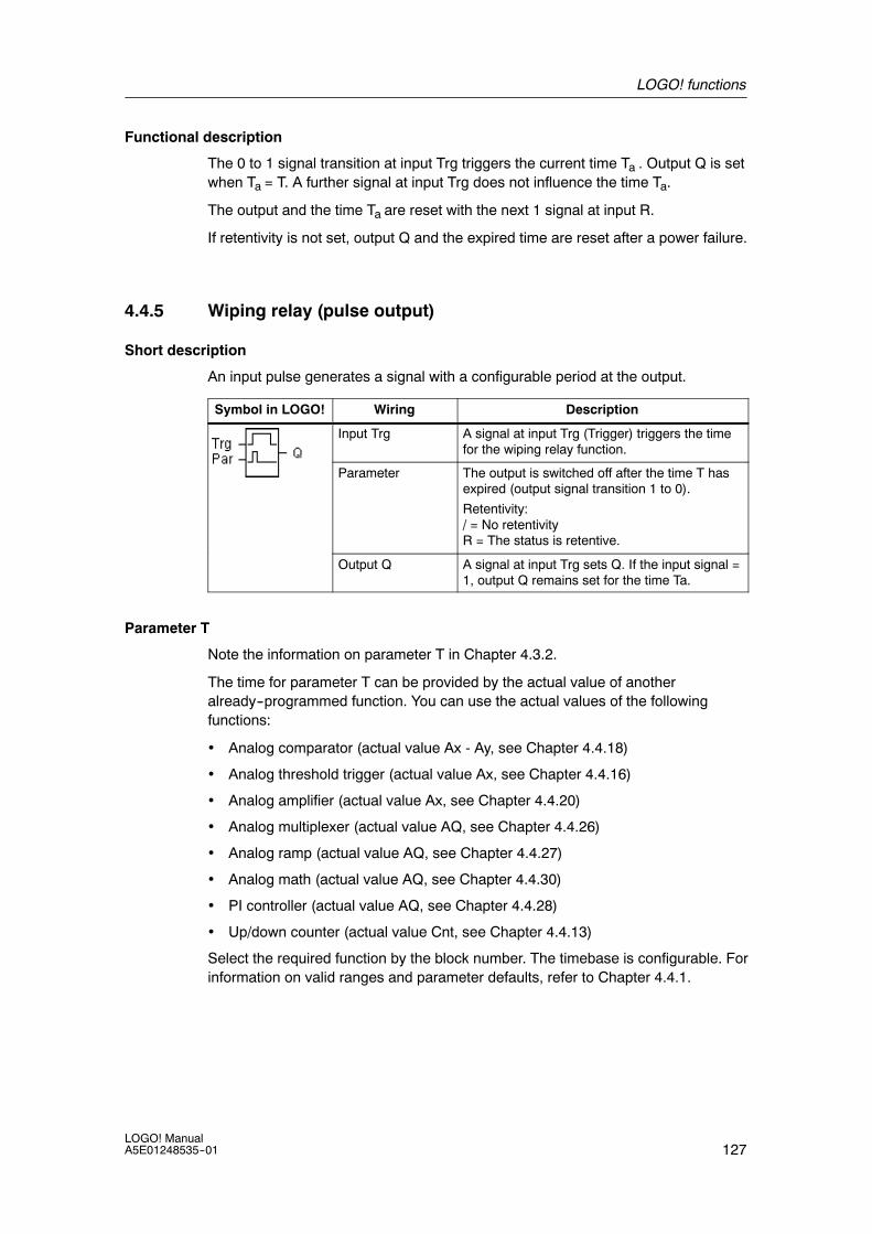
LOGO! functions
127LOGO! ManualA5E01248535--01
Functional description
The 0 to 1 signal transition at input Trg triggers the current time Ta . Output Q is setwhen Ta = T. A further signal at input Trg does not influence the time Ta.
The output and the time Ta are reset with the next 1 signal at input R.
If retentivity is not set, output Q and the expired time are reset after a power failure.
4.4.5 Wiping relay (pulse output)
Short description
An input pulse generates a signal with a configurable period at the output.
Symbol in LOGO! Wiring Description
Input Trg A signal at input Trg (Trigger) triggers the timefor the wiping relay function.
Parameter The output is switched off after the time T hasexpired (output signal transition 1 to 0).
Retentivity:/ = No retentivityR = The status is retentive.
Output Q A signal at input Trg sets Q. If the input signal =1, output Q remains set for the time Ta.
Parameter T
Note the information on parameter T in Chapter 4.3.2.
The time for parameter T can be provided by the actual value of anotheralready--programmed function. You can use the actual values of the followingfunctions:
• Analog comparator (actual value Ax - Ay, see Chapter 4.4.18)
• Analog threshold trigger (actual value Ax, see Chapter 4.4.16)
• Analog amplifier (actual value Ax, see Chapter 4.4.20)
• Analog multiplexer (actual value AQ, see Chapter 4.4.26)
• Analog ramp (actual value AQ, see Chapter 4.4.27)
• Analog math (actual value AQ, see Chapter 4.4.30)
• PI controller (actual value AQ, see Chapter 4.4.28)
• Up/down counter (actual value Cnt, see Chapter 4.4.13)
Select the required function by the block number. The timebase is configurable. Forinformation on valid ranges and parameter defaults, refer to Chapter 4.4.1.

LOGO! functions
128LOGO! Manual
A5E01248535--01
Timing diagram
Trg
T has not expiredTa is expiring
Q
The bold section of the timingdiagram also appears in the symbolof the wiping relay.
T
Functional description
A 0 to 1 transition at input Trg sets the output, and triggers a time Ta during whichthe output remains set.
Output Q is reset to lo (pulse output) when Ta reaches the value preset at T (Ta =T).
The output is immediately reset if there is a 1 to 0 transition at input Trg before thespecified time has expired.
If retentivity is not set, output Q and the expired time are reset after a power failure.
4.4.6 Edge triggered wiping relay
Short description
An input pulse generates a preset number of output pulses with a definedpulse/pause ratio (retriggerable), after a configured delay time has expired.
Symbol in LOGO! Wiring Description
Input Trg A signal at input Trg (Trigger) triggers the timesfor the edge triggered wiping relay.
Input R A signal at input R resets the current time (Ta)and the output.
Parameter The interpulse width TL and the pulse width THare configurable.
N determines the number of pulse/pause cyclesTL/TH:
Range of values: 1...9
Retentivity:/ = No retentivityR = The status is retentive.
Output Q Q is set after TL has expired, and reset afterTH has expired.

LOGO! functions
129LOGO! ManualA5E01248535--01
Parameters TH and TL
Note the information on parameter T in Chapter 4.3.2.
The pulse width TH and the interpulse width TL can be provided by the actualvalue of another already--programmed function. You can use the actual values ofthe following functions:
• Analog comparator (actual value Ax - Ay, see Chapter 4.4.18)
• Analog threshold trigger (actual value Ax, see Chapter 4.4.16)
• Analog amplifier (actual value Ax, see Chapter 4.4.20)
• Analog multiplexer (actual value AQ, see Chapter 4.4.26)
• Analog ramp (actual value AQ, see Chapter 4.4.27)
• Analog math (actual value AQ, see Chapter 4.4.30)
• PI controller (actual value AQ, see Chapter 4.4.28)
• Up/down counter (actual value Cnt, see Chapter 4.4.13)
Select the required function by the block number. The timebase is configurable. Forinformation on valid ranges and parameter defaults, refer to Chapter 4.4.1.
Timing diagram A
Trg
Ta is running
Q
The bold section of the timingdiagram also appears in thesymbol of the edge triggeredwiping relay.TH TH N=1
TL=0
Timing diagram B
Trg
N=2
Q
TL THTL TH TL THTL TH
Timing diagram for the sampleconfiguration
Functional description
A 0 to 1 transition at input Trg triggers the time TL (Time Low). After the time TL hasexpired, output Q is set for the duration of TH (Time High).
If there is a further 0 to 1 transition (retriggering pulse) at input Trg before thepreset time (TL + TH) has expired, Ta is reset and the pulse/pause cycle isrestarted.
If retentivity is not set, output Q and the time are reset after a power failure.
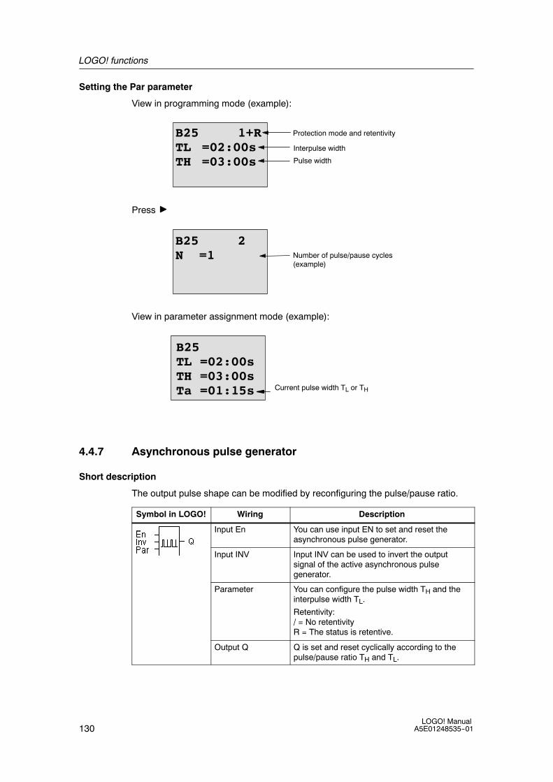
LOGO! functions
130LOGO! Manual
A5E01248535--01
Setting the Par parameter
View in programming mode (example):
B25 1+RTL =02:00sTH =03:00s
Protection mode and retentivity
Interpulse width
Pulse width
Press
B25 2N =1 Number of pulse/pause cycles
(example)
View in parameter assignment mode (example):
B25TL =02:00sTH =03:00sTa =01:15s Current pulse width TL or TH
4.4.7 Asynchronous pulse generator
Short description
The output pulse shape can be modified by reconfiguring the pulse/pause ratio.
Symbol in LOGO! Wiring Description
Input En You can use input EN to set and reset theasynchronous pulse generator.
Input INV Input INV can be used to invert the outputsignal of the active asynchronous pulsegenerator.
Parameter You can configure the pulse width TH and theinterpulse width TL.
Retentivity:/ = No retentivityR = The status is retentive.
Output Q Q is set and reset cyclically according to thepulse/pause ratio TH and TL.

LOGO! functions
131LOGO! ManualA5E01248535--01
Parameters TH and TL
Note the information on parameter T in Chapter 4.3.2.
The pulse width TH and the interpulse width TL can be provided by the actualvalue of another already--programmed function. You can use the actual values ofthe following functions:
• Analog comparator (actual value Ax - Ay, see Chapter 4.4.18)
• Analog threshold trigger (actual value Ax, see Chapter 4.4.16)
• Analog amplifier (actual value Ax, see Chapter 4.4.20)
• Analog multiplexer (actual value AQ, see Chapter 4.4.26)
• Analog ramp (actual value AQ, see Chapter 4.4.27)
• Analog math (actual value AQ, see Chapter 4.4.30)
• PI controller (actual value AQ, see Chapter 4.4.28)
• Up/down counter (actual value Cnt, see Chapter 4.4.13)
Select the required function by the block number. The timebase is configurable. Forinformation on valid ranges and parameter defaults, refer to Chapter 4.4.1.
Timing diagram
En
Inv
TH
Q
TL THTL TH TLTH
Functional description
You can configure the pulse/interpulse width at the TH (Time High) and TL (TimeLow) parameters.
Input Inv can be used to invert the output signal, provided the block is enabled witha signal at input EN.
If retentivity is not set, output Q and the expired time are reset after a power failure.

LOGO! functions
132LOGO! Manual
A5E01248535--01
4.4.8 Random generator
Short description
The output of the random generator is set or reset within a configured time.
Symbol in LOGO! Wiring Description
Input En A positive edge ( 0 to 1 transition) at input En(Enable) triggers the on-delay time of therandom generator.
A negative edge ( 1 to 0 transition) at input En(Enable) triggers the off-delay time of therandom generator.
Parameter The on-delay is set at random to a valuebetween 0 s and TH.
The off-delay is set at random to a valuebetween 0 s and TL.
Output Q Output Q is set when the on-delay has expiredand if En is still set. It is reset when theoff-delay has expired, provided En was not setagain meanwhile.
Parameter TH and TL
Note the defaults of the TH and TL parameters listed in Chapter 4.3.2.
The on--delay time TH and the off--delay time TL can be provided by the actualvalue of another already--programmed function. You can use the actual values ofthe following functions:
• Analog comparator (actual value Ax - Ay, see Chapter 4.4.18)
• Analog threshold trigger (actual value Ax, see Chapter 4.4.16)
• Analog amplifier (actual value Ax, see Chapter 4.4.20)
• Analog multiplexer (actual value AQ, see Chapter 4.4.26)
• Analog ramp (actual value AQ, see Chapter 4.4.27)
• Analog math (actual value AQ, see Chapter 4.4.30)
• PI controller (actual value AQ, see Chapter 4.4.28)
• Up/down counter (actual value Cnt, see Chapter 4.4.13)
Select the required function by the block number. The timebase is configurable. Forinformation on valid ranges and parameter defaults, refer to Chapter 4.4.1.
Timing diagram
En
T isbusy
Q
TLTH
The bold section ofthe timing diagramalso appears in thesymbol of the randomgenerator.

LOGO! functions
133LOGO! ManualA5E01248535--01
Functional description
The 0 to 1 transition at input En triggers a random on-delay time between 0 s andTH. The output is set when the on-delay time has expired and if the signal at inputEn remains hi at least for the duration of this time.
The time is reset if input En is reset before the on-delay time has expired.
A 1 to 0 transition at input EN triggers a random off-delay time between 0 s and TL.
The output is reset after the off-delay time has expired, provided input En remainslo at least for the duration of this time.
The time is reset if the signal at input En changes to 1 again before the off-delaytime has expired.
The time expired is reset after a power failure.

LOGO! functions
134LOGO! Manual
A5E01248535--01
4.4.9 Stairway lighting switch
Short description
An input edge triggers a configurable and retriggerable time. The output is resetafter this time has expired. A warning signal can be output before this time hasexpired to warn of the impending shutdown.
Symbol in LOGO! Wiring Description
Input Trg A signal at input Trg (Trigger) triggers theoff-delay time for the stairway lighting switch.
Parameter T represents the off-delay time of the output(output signal transition 1 to 0).
T! determines the triggering time for thepre-warning.
T!L determines the length of the pre-warningsignal.
Retentivity:/ = No retentivityR = The status is retentive.
Output Q Q is reset after the time T has expired. Awarning signal can be output before this timehas expired.
Parameter T, T! and T!L
Note the defaults of the T parameters listed in Chapter 4.3.2.
The off--delay time T, the pre--warning time T! and the pre--warning period T!L canbe provided by the actual value of another already--programmed function. You canuse the actual values of the following functions:
• Analog comparator (actual value Ax - Ay, see Chapter 4.4.18)
• Analog threshold trigger (actual value Ax, see Chapter 4.4.16)
• Analog amplifier (actual value Ax, see Chapter 4.4.20)
• Analog multiplexer (actual value AQ, see Chapter 4.4.26)
• Analog ramp (actual value AQ, see Chapter 4.4.27)
• Analog math (actual value AQ, see Chapter 4.4.30)
• PI controller (actual value AQ, see Chapter 4.4.28)
• Up/down counter (actual value Cnt, see Chapter 4.4.13)
Select the required function by the block number. The timebase is configurable. Forinformation on valid ranges and parameter defaults, refer to Chapter 4.4.1.
Timing diagram
Ta is busy
T
Q
Trg
T!LT!

LOGO! functions
135LOGO! ManualA5E01248535--01
Functional description
A 0 to 1 signal transition at input Trg sets output Q. The next 1 to 0 transition at Trgretriggers the current time Ta, and output Q remains set.
Output Q is reset when Ta = T. You can output a warning signal before the off-delaytime (T -- T!) has expired to reset Q for the time of the pre-warning period T!L.
A further one-shot at input Trg during Ta retriggers the time Ta .
If retentivity is not set, output Q and the expired time are reset after a power failure.
Setting the Par parameter
Note the defaults specified in Chapter 4.3.2.
Note
All times must have the same timebase.
View in programming mode (example):
B9 1+RT =60:00s
Protection mode and retentivity
Off-delay time
Press
B9 2T! =05:00sT!L =00:10s
Start of the off-warning period(T -- T!)Off-warning time
View in parameter assignment mode (example):
B9 1T =60:00s
Ta =06:00s Current value of T

LOGO! functions
136LOGO! Manual
A5E01248535--01
4.4.10 Multiple function switch
Short description
Switch with two different functions:
• Pulse switch with off-delay
• Switch (permanent lighting)
Symbol in LOGO! Wiring Description
Input Trg A signal at input Trg (Trigger) sets output Q(permanent light) or resets Q with an off-delay.When active, output Q can be reset with asignal at input Trg.
Input R A signal at input R resets the current time Taand resets the output.
Parameter T represents the off--delay time. The output isreset (1 to 0 transition) when time T expires.
TL represents the time during which the outputmust be set to enable the permanent lightfunction.
T! represents the on--delay for the prewarningtime.
T!L represents the length of the prewarning timeperiod.
Retentivity:/ = No retentivityR = The status is retentive.
Output Q A signal at Trg switches on output Q.Depending on the length of the input at Trg, theoutput is switched off again or switched onpermanently, or it is reset with a further signalat Trg.
Parameters T, TL, T! and T!L
Note the defaults of the T parameters listed in Chapter 4.3.2.
The off--delay time T, the permanent light time TL, the on--delay prewarning time T!and the prewarning time period T!L can be provided by the actual value of anotheralready--programmed function. You can use the actual values of the followingfunctions:
• Analog comparator (actual value Ax - Ay, see Chapter 4.4.18)
• Analog threshold trigger (actual value Ax, see Chapter 4.4.16)
• Analog amplifier (actual value Ax, see Chapter 4.4.20)
• Analog multiplexer (actual value AQ, see Chapter 4.4.26)
• Analog ramp (actual value AQ, see Chapter 4.4.27)
• Analog math (actual value AQ, see Chapter 4.4.30)
• PI controller (actual value AQ, see Chapter 4.4.28)
• Up/down counter (actual value Cnt, see Chapter 4.4.13)
Select the required function by the block number. The timebase is configurable. Forinformation on valid ranges and parameter defaults, refer to Chapter 4.4.1.

LOGO! functions
137LOGO! ManualA5E01248535--01
Timing diagram
Ta is busy
T
Q
TrgTLTL
T!LT!
Functional description
A 0 to 1 transition at input Trg sets output Q.
If output Q = 0, and input Trg is set hi at least for the duration of TL, the permanentlighting function is enabled and output Q is set accordingly.
The off-delay T is triggered when input Trg returns to 0 before TL has expired.
Output Q is reset when Ta = T.
You can output an off-warning signal prior to the expiration of the off-delay time(T -- T!) that resets Q for the duration of the prewarning time period T!L. Asubsequent signal at Trg always resets T and the output Q.
If retentivity is not set, output Q and the expired time are reset after a power failure.
Setting the Par parameter
Note the defaults specified in Chapter 4.3.2.
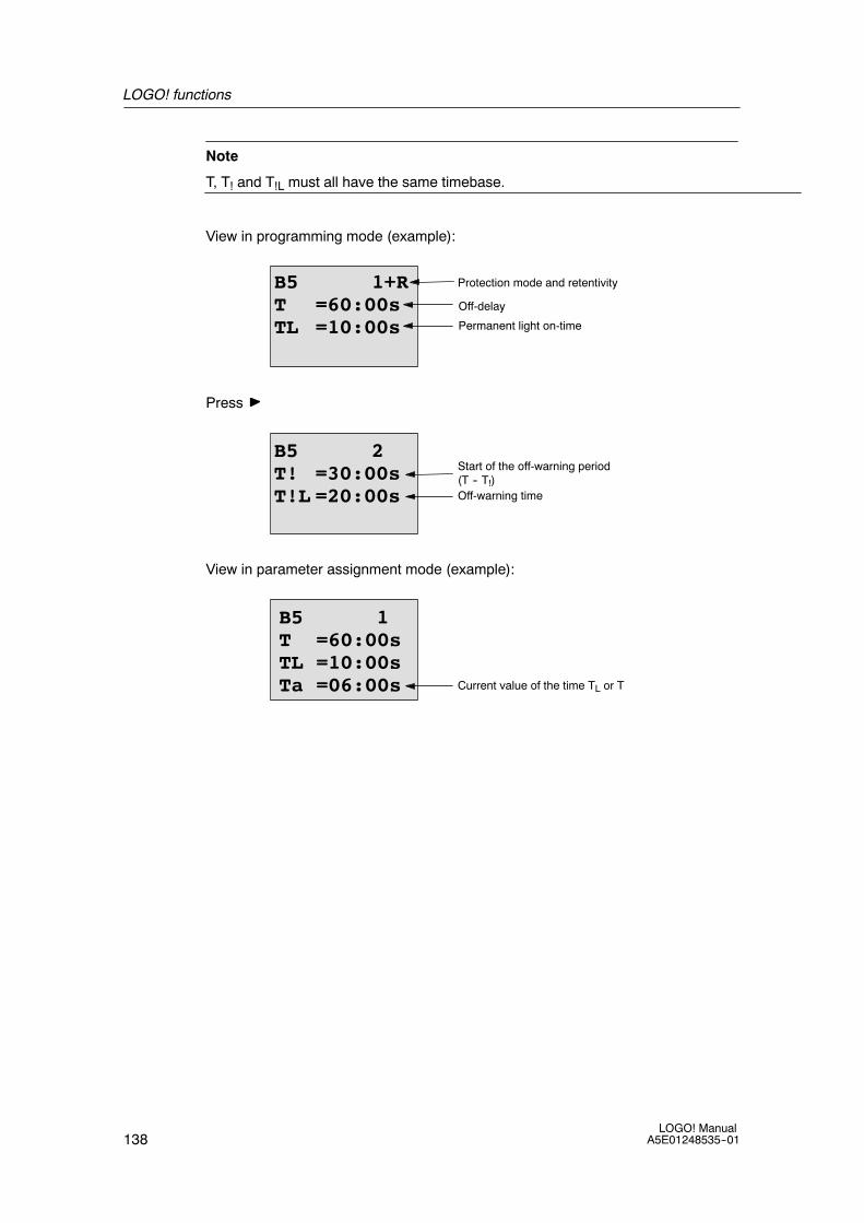
LOGO! functions
138LOGO! Manual
A5E01248535--01
Note
T, T! and T!L must all have the same timebase.
View in programming mode (example):
B5 1+RT =60:00sTL =10:00s
Protection mode and retentivity
Off-delay
Permanent light on-time
Press
B5 2T! =30:00sT!L =20:00s
Start of the off-warning period(T -- T!)Off-warning time
View in parameter assignment mode (example):
B5 1T =60:00sTL =10:00sTa =06:00s Current value of the time TL or T

LOGO! functions
139LOGO! ManualA5E01248535--01
4.4.11 Weekly timer
Short description
The output is controlled by means of a configurable on/off date. The functionsupports any combination of weekdays. You select the active weekdays by hidingthe inactive days.
Note
Because the LOGO! 24/24o does not have a real-time clock, the weekly timerfunction is not available for this version.
Symbol inLOGO!
Wiring Description
Camparameters 1,2, and 3
At the Cam parameters, you set the on- and off-timesof the weekly timer for each Cam switch. Here youalso configure the days and the time-of-day.
Par You specify whether the timer pulses on for one cyclewhen activated and then reset. The pulse settingapplies to all three cams.
Output Q Q is set when the configured cam is actuated.
Timing diagram (three examples)
1Cam
Monday WednesdayTuesday Saturday
FridayThursday
Sunday
1 31 2 3
Q
1 1 11
Cam 1: Daily: 06:30 h to 8:00 h
Cam 2: Tuesday: 03:10 h to 04:15 h
Cam 3: Saturday and Sunday: 16:30 h to 23:10 h
Functional description
Each weekly timer has three cams you can use to configure a time hysteresis. Youspecify the on- and off-times at the Cam parameters. The weekly timer sets theoutput at a certain on-time, if this is not already set.
The weekly timer resets the output at a certain off-time if you configured anoff--time, or at the end of the cycle if you specified a pulse output. You will cause aconflict if the on- and off-times you set for the weekly timer are identical, though seton different cams. In this case, cam3 takes priority over cam2, whereas cam2takes priority over cam1.
The switching state of the weekly timer is determined by the status of all threecams.
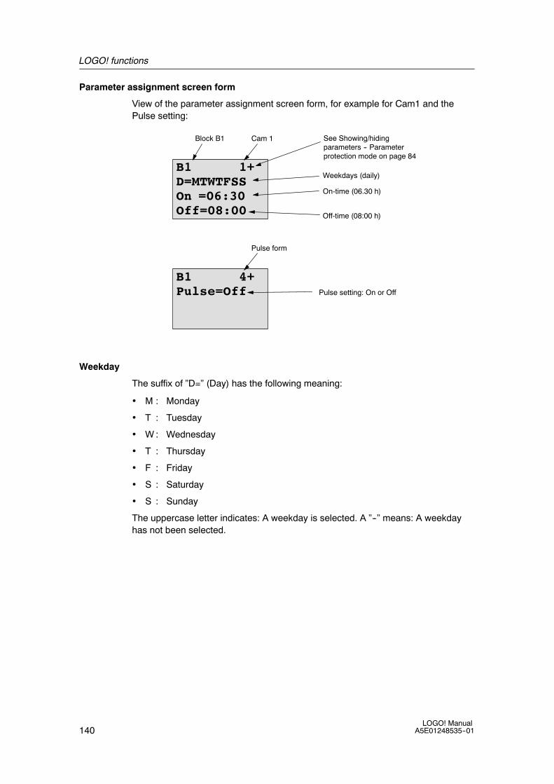
LOGO! functions
140LOGO! Manual
A5E01248535--01
Parameter assignment screen form
View of the parameter assignment screen form, for example for Cam1 and thePulse setting:
B1 1+D=MTWTFSSOn =06:30Off=08:00
On-time (06.30 h)
See Showing/hidingparameters -- Parameterprotection mode on page 84
Off-time (08:00 h)
Block B1 Cam 1
Weekdays (daily)
B1 4+Pulse=Off
Pulse form
Pulse setting: On or Off
Weekday
The suffix of ”D=” (Day) has the following meaning:
• M : Monday
• T : Tuesday
• W : Wednesday
• T : Thursday
• F : Friday
• S : Saturday
• S : Sunday
The uppercase letter indicates: A weekday is selected. A ”--” means: A weekdayhas not been selected.
LOGO! functions
141LOGO! ManualA5E01248535--01
On-/Off-times
Any time between 00:00 h and 23:59 h is possible.You can also configure the ontime to be a pulse signal. The timer block will be activated at the specified time forone cycle and then the output is reset.----:---- means: No on-/off-times set.
Setting the weekly timer
To set the on-/off-times:
1. Move the cursor to one of the Cam parameters of the timer (e.g. No1).
2. Press OK. LOGO! opens the Cam parameter assignment screen form. Thecursor is positioned on the weekday.
3. Press and to select one or several weekdays.
4. Press to move the cursor to the first position of the on-time.
5. Set the on-time.Modify the value at the respective position, using the keys and . Move to thecursor to the various positions, using the keys and . At the first position, youcan only select the value ----:----(----:---- means: No on-/off-times set).
6. Press to move the cursor to the first position of the off-time.
7. Set the off-time (in same way as in step 5).
8. Confirm your entries with OK.
The cursor is now positioned on the No2 parameter (Cam2) and you canconfigure a further cam.
Note
For information on timer accuracy, refer to the technical data and to Chapter 4.3.2.
Weekly timer: Example
The output of the weekly timer switch is to be set daily from 06:30 h to 08:00 h. Theoutput should also be set every Tuesday from 03:10 h to 04:15 h, and on theweekends from 16:30 h to 23:10 h.
This requires three cams.
Here are the parameter assignment screen forms of the cams No 1, 2 and 3, basedon the timing diagram shown earlier.

LOGO! functions
142LOGO! Manual
A5E01248535--01
Cam1
Cam No1 must set the output of the weekly timer daily from 06:30 h to 08:00 h.
B1 1+D=MTWTFSSOn =06:30Off=08:00
Cam2
Cam No2 must set the output of the weekly timer every Tuesday from 03:10 h to04:15 h.
B1 2D=-T-----On =03:10Off=04:15
Cam3
Cam No3 must set the output of the weekly timer switch every Saturday andSunday from 16:30 h to 23:10 h.
B1 3D=-----SSOn =16:30Off=23:10
Result
1Cam
Monday WednesdayTuesday Saturday
FridayThursday
Sunday
1 31 2 3
Q
1 1 11

LOGO! functions
143LOGO! ManualA5E01248535--01
4.4.12 Yearly timer
Short description
The output is controlled by means of a configurable on/off date. You can configurethe timer to activate on a yearly, monthly, or user-defined time basis. With anymode, you can also configure the timer to pulse the output during the defined timeperiod. The time period is configurable within the date range of January 1, 2000 toDecember 31, 2099
Note
Because LOGO! 24/24o does not have a real-time clock, the yearly timer is notavailable for this version.
Symbol in LOGO! Wiring Description
Cam parameter At the Cam parameter, you configure the timermode, the on-/off-times for the timer, andwhether the output is a pulse output.
Output Q Q is set when the configured cam is switchedon.
Timing diagrams
Example 1: Yearly mode on, Monthly mode off, Pulse Off, On Time = 2000--06--01,Off Time = 2099--08--31: Every year on June 1 the timer output switches on andremains on until August 31.
B6 2+ON :YYYY-MM-DD2000-06-01
B6 1+Yearly = OnMonthly=OffPulse =Off
B6 3+OFF :YYYY-MM-DD2099-08-31

LOGO! functions
144LOGO! Manual
A5E01248535--01
Example 2: Yearly mode on, Monthly mode off, Pulse on, On Time = 2000--03--15,Off Time = 2099--**--**: Every year on March 15, the timer switches on for onecycle.
B6 2+ON :YYYY-MM-DD2000-03-15
B6 1+Yearly = OnMonthly=OffPulse = On
B6 3+OFF :YYYY-MM-DD2099-**-**
Example 3: Yearly mode on, Monthly mode off, Pulse off, On Time = 2008--06--01,Off Time = 2010--08--31: On June 1 of 2008, 2009, and 2010 the timer outputswitches on and remains on until August 31.
B6 2+ON :YYYY-MM-DD2008-06-01
B6 1+Yearly = OnMonthly=OffPulse =Off
B6 3+OFF :YYYY-MM-DD2010-08-31

LOGO! functions
145LOGO! ManualA5E01248535--01
Example 4: Yearly mode on, Monthly mode off, Pulse on, On Time = 2008--03--15,Off Time = 2010--**--**: On March 15 of 2008, 2009, and 2010, the timer outputswitches on for one cycle.
B6 2+ON :YYYY-MM-DD2008-03-15
B6 1+Yearly = OnMonthly=OffPulse = On
B6 3+OFF :YYYY-MM-DD2010-**-**
Example 5: Yearly mode off, Monthly mode off, Pulse off, On Time = 2008--06--01,Off Time = 2008--08--31: On June 1, 2008 the timer output switches on andremains on until August 31, 2010.
B6 2+ON :YYYY-MM-DD2008-06-01
B6 1+Yearly =OffMonthly=OffPulse =Off
B6 3+OFF :YYYY-MM-DD2010-08-31

LOGO! functions
146LOGO! Manual
A5E01248535--01
Example 6: Yearly mode off, Monthly mode off, Pulse selected, On Time =2008--03--15, Off Time = ****--**--**: On March 15, 2008 the timer output switcheson for one cycle. Because the timer does not have a monthly action or yearlyaction, the timer output pulses only one time at the specified On Time.
B6 2+ON :YYYY-MM-DD2008-03-15
B6 1+Yearly =OffMonthly=OffPulse =On
B6 3+OFF :YYYY-MM-DD****-**-**
Example 7: Yearly mode on, Monthly mode off, Pulse off, On Time = 2008--12--15,Off Time = 2010--01--07: On December 15 of 2008 and 2009, the timer outputswitches on and remains on until January 7 of the following year. When the timeroutput turns off on January 7, 2010 it does NOT turn on again the followingDecember 15.
B6 2+ON :YYYY-MM-DD2008-12-15
B6 1+Yearly = OnMonthly=OffPulse =Off
B6 3+OFF :YYYY-MM-DD2010-01-07

LOGO! functions
147LOGO! ManualA5E01248535--01
Example 8: Yearly mode on, Monthly mode on, On Time = 2008--**--01, Off Time =2010--**--05: Starting in 2008, on the first day of each month the timer outputswitches on and switches off on the fifth day of the month. The timer continues inthis pattern through the last month of 2010.
B6 2+ON :YYYY-MM-DD2008-**-01
B6 1+Yearly =OnMonthly=OnPulse =Off
B6 3+OFF :YYYY-MM-DD2010-**-05
Functional description
The yearly timer sets and resets the output at specific on and off dates. Sets andresets are executed at 00:00. If your application requires a different time, use aweekly timer together with a yearly timer in your circuit program.
The on time specifies when the timer is activated. The off time specifies when theoutput is reset again. For the on and off times, note the order of the fields: The firstfield defines the year, the second the month and the third the day.
If you set the Monthly mode on, the timer output switches on each month at thespecified day of the on time and remains on until the specified day of the off time.The on time specifies the initial year in which the timer is activated. The off timedefines the last year in which the timer turns off. The maximum year is 2099.
If you set the Yearly mode on, the timer output switches on each year at thespecified month and day of the on time and remains on until the specified monthand day of the off time. The on time specifies the initial year in which the timer isactivated. The off time defines the last year in which the timer turns off. Themaximum year is 2099.
If you set Pulse output, the timer output switches on at the specified on time for onecycle and then the timer output is reset. You can choose to pulse a timer on amonthly or yearly basis, or just a single time.
If you set none of the Monthly, Yearly, or Pulse modes on, you can define a specifictime period with the on time and off time. It can span any time period that youchoose.
For a process action that is to be switched on and off at multiple but irregular timesduring the year, you can define multiple yearly timers with the outputs connected byan OR function block.

LOGO! functions
148LOGO! Manual
A5E01248535--01
Backup of the real--time clock
The internal real--time clock of LOGO! is buffered against power failure. Thebuffering time is influenced by the ambient temperature, and is typically 80 hours atan ambient temperature of 25˚C. If you are using the optional LOGO! Battery card,or combined LOGO! Memory/Battery card, LOGO! can retain the clock time for upto two years.
Sample configuration
The output of a LOGO! is to be set annually on March 1, reset on April 4, set againon July 7, and reset again on November 19. You need to configure two yearlytimers with corresponding on-times. Then logically link the outputs by means of anOR block.
Yearly Timer 1
On-time Mar 1
Off-time Apr 4
B1 2+ON :YYYY-MM-DD2000-03-01
B1 1+Yearly = OnMonthly=OffPulse =Off
B1 3+OFF :YYYY-MM-DD2099-04-04
Yearly Timer 2
On-time Jul 7
Off-time Nov 19
B2 2+ON :YYYY-MM-DD2000-07-07
B2 1+Yearly = OnMonthly=OffPulse =Off
B2 3+OFF :YYYY-MM-DD2099-11-19
Result
On
Off
March 1at 00:00 h
April 4at 00:00 h
B1 B2
July 7at 00:00 h
November 19at 00:00 h

LOGO! functions
149LOGO! ManualA5E01248535--01
4.4.13 Up/down counter
Short description
An input pulse increments or decrements an internal value, depending on theparameter setting. The output is set or reset when a configured threshold isreached. The direction of count can be changed with a signal at input Dir.
Symbol in LOGO! Wiring Description
Input R A signal at input R resets the internal countvalue to zero.
Input Cnt The function counts the 0 to 1 transitions atinput Cnt. 1 to 0 transitions are not counted.
Use
• inputs I3, I4, I5, and I6 for fast counting(only LOGO! 12/24 RC/RCo and LOGO!24/24o): max. 5 kHz.
• any other input or circuit component forcounting low frequency signals (typ. 4 Hz).
Input Dir You set the direction of count at input Dir:
Dir = 0: Up countDir = 1: Down count
Parameter On: On thresholdRange of values:0...999999
Off: Off thresholdRange of values:0...999999
StartVal: Initial value from which to begincounting either down or up.
Retentivity for internal counter value Cnt:/ = No retentivityR = The status is retentive.
Output Q Q is set or reset, depending on the currentvalue at Cnt and the set thresholds.
Parameters On and Off
The on threshold On and the off threshold Off can be provided by the actual valueof another already--programmed function. You can use the actual values of thefollowing functions:
• Analog comparator (actual value Ax - Ay, see Chapter 4.4.18)
• Analog threshold trigger (actual value Ax, see Chapter 4.4.16)
• Analog amplifier (actual value Ax, see Chapter 4.4.20)
• Analog multiplexer (actual value AQ, see Chapter 4.4.26)
• Analog ramp (actual value AQ, see Chapter 4.4.27)
• Analog math (actual value AQ, see Chapter 4.4.30)
• PI controller (actual value AQ, see Chapter 4.4.28)
• Up/down counter (actual value Cnt, see Chapter 4.4.13)
Select the required function by the block number.

LOGO! functions
150LOGO! Manual
A5E01248535--01
Timing diagram
R
Dir
On=Off=5
Cnt
StartVal
Internalcount valueCnt
Q
Functional description
The internal counter increments (Dir = 0) or decrements (Dir = 1) by one count withevery positive edge at input Cnt.
You can use input R to reset the internal count value to the start value. As long asR = 1, the output is also 0 and the pulses at input Cnt are not counted.
If retentivity is not set, output Q and the expired time are reset after a power failure.
Q is set or reset depending on the current value at Cnt and the set thresholds. Seethe calculation rule below.
Calculation rule
• If the On threshold ² Off threshold, then:Q = 1, if Cnt ² OnQ = 0, if Cnt < Off.
• If the On threshold < Off threshold, then Q = 1,if On ± Cnt < Off.
Note
The system scans the counter limit value cyclically.
Thus, if the pulse frequency at the fast digital inputs I3, I4, I5 or I6 is faster than thecycle time, the special function might not switch until after the specified limit valueis exceeded
Example: Up to 100 pulses per cycle can be counted; 900 pulses have beencounted so far. On = 950; Off = 10000. The output is set in the next cycle, after thevalue has reached 1000. (The output would not be set at all if the value Off = 980.)

LOGO! functions
151LOGO! ManualA5E01248535--01
View in programming mode (example):
B3 1+ROn =001234Off=000000
or
B3 1+ROn =123456Off!B021
To set the start value, press or to access the following screen form:
B3 2+RSTV =0100
If the referenced block (B021, in the example) returns a value that lies out of thevalid range, the value is rounded to the next valid value.
The view in parameter assignment mode (example):
B3On =001234Off=000000Cnt=000120
orB3On =123456Off!B021Cnt=000120Current
count value

LOGO! functions
152LOGO! Manual
A5E01248535--01
4.4.14 Hours counter
Short description
A configured time is triggered with a signal at the monitoring input. The output isset when this time has expired.
Symbol in LOGO! Wiring Description
Input R A positive edge (0 to 1 transition) at input Rresets output Q and sets a configured value MIat the counter for the duration of the time-to-go(MN).
Input En En is the monitoring input. LOGO! scans theon-time of this input.
Input Ral A positive edge at input Ral (Reset all) resetsthe hours counter (OT) and the output, and setsthe time-to-go value (MN) tothe maintenanceinterval MI:
• output Q = 0,
• measured operating time OT = 0 and
• the time-to-go of the maintenance intervalMN = MI.
Parameter MI: Maintenance interval to be preset in units ofhours and minutesRange of values:0000...9999 h, 0...59 m
OT: The accumulated total operating time; youcan specify an offset in hours andminutesRange of values:00000...99999 h, 0...59 m
Q!0:
• When ”R” is selected:Q = 1, if MN = 0;Q = 0, if R = 1 or Ral = 1
• When ”R+En” is selected:Q = 1, if MN = 0;Q = 0, if R = 1 or Ral = 1 or En = 0.
Output Q The output is set when the time-to-go MN = 0(see timing diagramm).
The output is reset:
• When ”Q!0:R+En”, ifR = 1 or Ral = 1 or En = 0
• When ”Q!0:R”, if R = 1 or Ral = 1.
MI = Configured time intervalMN= Time-to-goOT= Total time expired since the last hi signal at input RalThese values are always retentive!
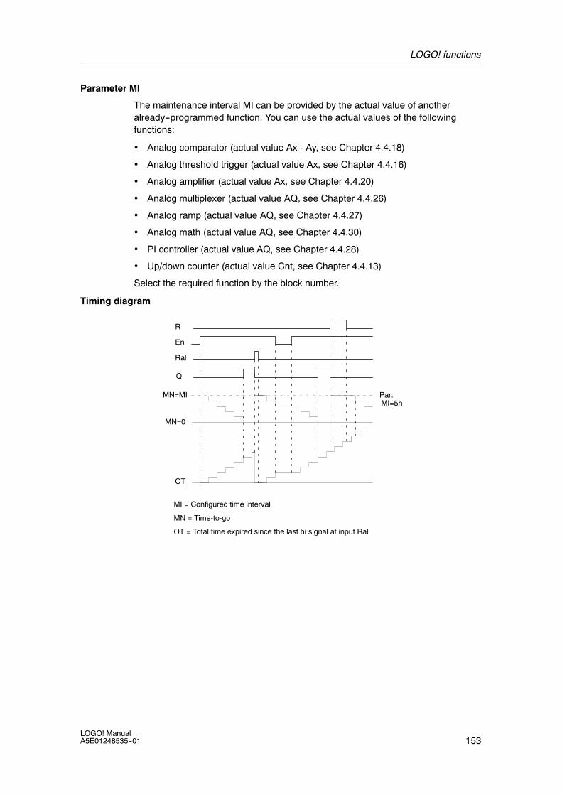
LOGO! functions
153LOGO! ManualA5E01248535--01
Parameter MI
The maintenance interval MI can be provided by the actual value of anotheralready--programmed function. You can use the actual values of the followingfunctions:
• Analog comparator (actual value Ax - Ay, see Chapter 4.4.18)
• Analog threshold trigger (actual value Ax, see Chapter 4.4.16)
• Analog amplifier (actual value Ax, see Chapter 4.4.20)
• Analog multiplexer (actual value AQ, see Chapter 4.4.26)
• Analog ramp (actual value AQ, see Chapter 4.4.27)
• Analog math (actual value AQ, see Chapter 4.4.30)
• PI controller (actual value AQ, see Chapter 4.4.28)
• Up/down counter (actual value Cnt, see Chapter 4.4.13)
Select the required function by the block number.
Timing diagram
MI = Configured time interval
MN = Time-to-go
OT = Total time expired since the last hi signal at input Ral
Par:
Q
R
Ral
En
MN=MI
OT
MN=0
MI=5h
LOGO! functions
154LOGO! Manual
A5E01248535--01
Functional description
The hours counter monitors input En. When En = 1, LOGO! computes the timeexpired and the time-to-go MN. LOGO! shows these times in parameterassignment mode. Output Q is set when the time-to-go MN = 0.
A signal at reset input R resets output Q and sets the preset value of MI at thecounter for the duration of MN. The hours counter OT is not affected.
With a signal at the reset input Ral, you reset output Q and set the preset value ofMI at the counter for the duration of MN. The hours counter OT is reset to zero.
Depending on your configuration of parameter Q, the output is either reset with asignal at inputR or Ral (”Q!0:R”), or when a reset signal is set hi, or the En signal is set lo(”Q!0:R+En”).
Viewing the MI, MN and OT values
• LOGO! Basic with display unit: You can open the parameter assignment modewhen the system is in RUN to view the actual values of MI, MN and OT.
• LOGO! Basic without display unit: In LOGO!Soft Comfort, you can use theOnline Test to read these values (for further information, see Chapter 7).
Limit value of OT
The value of the operating hours in OT are retained when you reset the hourscounter with a signal at input R. The hours counter OT continues the count as longas En = 1, irrespective of the status at the reset input R.
The counter limit of OT is 99999 h.The hours counter stops when it reaches this value.
In programming mode, you can set the initial value of OT. The counter startsoperation at any value other than zero. MN is automatically calculated at theSTART, based on the MI and OT values(Example: MI is a reference parameter to the actual value of Block 1, which is 100.OT = 30, the result is MN = 70).

LOGO! functions
155LOGO! ManualA5E01248535--01
Setting the Par parameter
View in programming mode:
B16 1+RB16 1+RMI-> B001hMI = 0100h
00 m
B16 2+ROT =00030h
00 m
B16 3+RQ!0:R+En
MI is the configurable time interval. The permissible range of values is 0 to 9999hours.
For information on how to assign the actual value of another already--programmedfunction to a parameter, see section 4.4.1
View in parameter assignment mode:
B16 1MI = 0100h
00 mTime interval
B16 2OT =00083h
15 mTotal operating hours
B16 3MN = 0016h
45 mTime-to-go

LOGO! functions
156LOGO! Manual
A5E01248535--01
4.4.15 Threshold trigger
Short description
The output is set and reset with two configurable threshold triggers.
Symbol in LOGO! Wiring Description
FreInput Fre The function counts the 0 to 1 transitions at
input Fre. 1 to 0 transitions are not counted.
Use
• inputs I3, I4, I5, I6 for fast counting (onlyLOGO! 12/24 RC/RCo and LOGO! 24/24o):max. 5 kHz.
• any other input or circuit component forcounting low frequency signals (typ. 4 Hz).
Parameter On: On thresholdRange of values:0000...9999
Off: Off thresholdRange of values:0000...9999
G_T: Time interval or gate time during whichthe input pulses are measured.Range of values:00:05 s...99:99 s
Output Q Q is set and reset at the thresholds.
Parameter G_T
The gate time G_T can be provided by the actual value of anotheralready--programmed function. You can use the actual values of the followingfunctions:
• Analog comparator (actual value Ax - Ay, see Chapter 4.4.18)
• Analog threshold trigger (actual value Ax, see Chapter 4.4.16)
• Analog amplifier (actual value Ax, see Chapter 4.4.20)
• Analog multiplexer (actual value AQ, see Chapter 4.4.26)
• Analog ramp (actual value AQ, see Chapter 4.4.27)
• Analog math (actual value AQ, see Chapter 4.4.30)
• PI controller (actual value AQ, see Chapter 4.4.28)
• Up/down counter (actual value Cnt, see Chapter 4.4.13)
Select the required function by the block number.
Timing diagram
Q
Off = 5fa = 9 fa = 10 fa = 8 fa = 4
G_T
Fre On = 9
fa = Input frequency

LOGO! functions
157LOGO! ManualA5E01248535--01
Functional description
The threshold trigger measures the signals at input Fre. The pulses are recordedacross a configurable time G_T.
Output Q is set and reset in accordance with the set thresholds. See the calculationrule below.
Calculation rule
• If the On threshold ² Off threshold, then:Q = 1, if fa > OnQ = 0, if fa ± Off.
• If the On threshold < Off threshold, then Q = 1 ifOn ± fa < Off.
Setting the Par parameter
Note
The system scans the counter limit value once per interval G_T.
View in programming mode (example):
B15 1+On =0009Off =0005
Parameter protection mode
On threshold
Off threshold
Press
B15 2G_T=01:00s Time interval for pulses
(example)

LOGO! functions
158LOGO! Manual
A5E01248535--01
Note
The ”seconds” timebase is here set as permanent default.
When you preset a time G_T of 1 s, LOGO! returns the current frequency inparameter fa in Hz.
View in parameter assignment mode (example):
B15On =0009Off =0005fa =0010
On threshold
Off threshold
Q = 1 (fa > On)
Note
fa always represents the total pulses measured per time unit G_T.

LOGO! functions
159LOGO! ManualA5E01248535--01
4.4.16 Analog threshold trigger
Short description
The output is set and reset at two configurable thresholds.
Symbol in LOGO! Wiring Description
Input Ax You apply the analog signal to be analyzed atinput Ax.
Use the analog inputs AI1...AI8 (*), the analogflags AM1...AM6, the block number of afunction with analog output, or the analogoutputs AQ1 and AQ2.
Parameter A: GainRange of values:¦10.00
B: Zero offsetRange of values:¦10,000
On: On thresholdRange of values:¦20,000
Off: Off thresholdRange of values:¦20,000
p: Number of decimalsRange of values:0, 1, 2, 3
Output Q Q is set or reset by the threshold triggers.
* AI1...AI8: 0...10 V corresponds with 0...1000 (internal value).
Gain and offset parameters
Please note the information on gain and offset parameters in Chapter 4.3.6.
Parameters On and Off
The On and Off parameters can be provided by the actual value of anotheralready--programmed function. You can use the actual values of the followingfunctions:
• Analog comparator (actual value Ax - Ay, see Chapter 4.4.18)
• Analog threshold trigger (actual value Ax, see Chapter 4.4.16)
• Analog amplifier (actual value Ax, see Chapter 4.4.20)
• Analog multiplexer (actual value AQ, see Chapter 4.4.26)
• Analog ramp (actual value AQ, see Chapter 4.4.27)
• Analog math (actual value AQ, see Chapter 4.4.30)
• PI controller (actual value AQ, see Chapter 4.4.28)
• Up/down counter (actual value Cnt, see Chapter 4.4.13)
Select the required function by the block number.
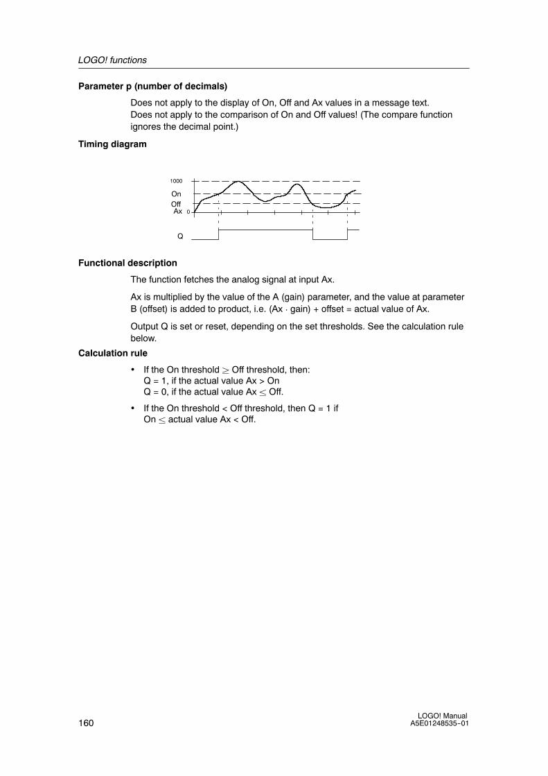
LOGO! functions
160LOGO! Manual
A5E01248535--01
Parameter p (number of decimals)
Does not apply to the display of On, Off and Ax values in a message text.Does not apply to the comparison of On and Off values! (The compare functionignores the decimal point.)
Timing diagram
Q
1000
0Ax
OnOff
Functional description
The function fetches the analog signal at input Ax.
Ax is multiplied by the value of the A (gain) parameter, and the value at parameterB (offset) is added to product, i.e. (Ax ¡ gain) + offset = actual value of Ax.
Output Q is set or reset, depending on the set thresholds. See the calculation rulebelow.
Calculation rule
• If the On threshold ² Off threshold, then:Q = 1, if the actual value Ax > OnQ = 0, if the actual value Ax ± Off.
• If the On threshold < Off threshold, then Q = 1 ifOn ± actual value Ax < Off.

LOGO! functions
161LOGO! ManualA5E01248535--01
Setting the Par parameter
The gain and offset parameters are used to adapt the sensors to the relevantapplication.
View in programming mode (example):
B3 1+On =+04000Off =+02000
Parameter protection mode
On threshold
Off threshold
Press
Decimals in the message text
B3 2A =01.00B =+00000p =2
Offset
Gain
View in parameter assignment mode (example):
B3On =+04000Off =+02000Ax =+05000
On threshold
Off threshold
Q = 1 (Ax > On)
View in the message text (example):
+050.00 Ax, when p = 2
Q = 1 (Ax > On)

LOGO! functions
162LOGO! Manual
A5E01248535--01
4.4.17 Analog differential trigger
Short description
The output is set and reset depending on a configurable threshold and a differentialvalue.
Symbol in LOGO! Wiring Description
Input Ax You apply the analog signal to be analyzed atinput Ax.
Use the analog inputs AI1...AI8 (*), the analogflags AM1...AM6, the block number of afunction with analog output, or the analogoutputs AQ1 and AQ2.
Parameter A: GainRange of values:¦10.00
B: Zero offsetRange of values:¦10,000
On: On/Off thresholdRange of values:¦20,000
n: Differential value forcalculating the offparameterRange of values:¦20,000
p: Number of decimalsRange of values:0, 1, 2, 3
Output Q Q is set or reset, depending on the thresholdand difference values.
* AI1...AI8: 0...10 V corresponds with 0...1000 (internal value).
Gain and offset parameters
Please note the information on gain and offset parameters in Chapter 4.3.6.

LOGO! functions
163LOGO! ManualA5E01248535--01
Parameter p (number of decimals)
Does not apply to the display of On, Off and Ax values in a message text.
Timing diagram A: Function with negative difference n
Q
O
n
Ax
Off = On + n
Timing diagram B: Function with positive difference n
Q
Off = On + n
Ax
On
Functional description
The function fetches the analog signal at input Ax.
Ax is multiplied by the value of the A (gain) parameter, and the value at parameterB (offset) is added to product, i.e. (Ax ¡ gain) + offset = actual value of Ax.
Output Q is set or reset, depending on the set (On) thresold and difference value(n). The function automatically calculates the Off parameter: Off = On + n,whereby n may be positive or negative. See the calculation rule below.
Calculation rule
• When you set a negative differential value n, the On threshold ² Off threshold,and:Q = 1, if the actual value Ax > OnQ = 0, if the actual value Ax ± Off.See the timing diagram A.
• When you set a positive differential value n, the On threshold < the Offthreshold, and Q = 1, if:On ± actual value Ax < Off.See the timing diagram B.

LOGO! functions
164LOGO! Manual
A5E01248535--01
Setting the Par parameter
The gain and offset parameters are used to adapt the sensors to the relevantapplication.
View in programming mode (example):
B3 1+On =+04000n =-02000
Parameter protection mode
On/off threshold
Differential value for the on/offthreshold
Press
Decimals in the message text
B3 2A =01.00B =+00000p =2
Offset
Gain
View in parameter assignment mode (example):
B3On =+04000n =-02000Ax =+05000
On thresholdDifferential value for theoff threshold
Q = 1 (Ax > On)
Press
B3Off =+02000 Off threshold

LOGO! functions
165LOGO! ManualA5E01248535--01
4.4.18 Analog comparator
Short description
The output is set and reset depending on the difference Ax -- Ay and on twoconfigurable thresholds.
Symbol in LOGO! Wiring Description
Inputs Ax and Ay You apply the analog signals the difference ofwhich you want to analyze at the inputs Ax andAy.
Use the analog inputs AI1...AI8 (*), the analogflags AM1...AM6, the block number of afunction with analog output, or the analogoutputs AQ1 and AQ2.
Parameter A: GainRange of values:¦10.00
B: Zero offsetRange of values:¦10,000
On: On thresholdRange of values:¦20,000
Off: Off thresholdRange of values:¦20,000
p: Number of decimalsRange of values:0, 1, 2, 3
Output Q Q is set or reset, depending on the differenceAx -- Ay and the set thresholds..
* AI1...AI8: 0...10 V corresponds with 0...1000 (internal value).
Gain and offset parameters
For more information on the gain and offset parameters, refer to Chapter 4.3.6.
Parameters On and Off
The on threshold On and the off threshold Off can be provided by the actual valueof another already--programmed function. You can use the actual values of thefollowing functions:
• Analog comparator (actual value Ax - Ay, see Chapter 4.4.18)
• Analog threshold trigger (actual value Ax, see Chapter 4.4.16)
• Analog amplifier (actual value Ax, see Chapter 4.4.20)
• Analog multiplexer (actual value AQ, see Chapter 4.4.26)
• Analog ramp (actual value AQ, see Chapter 4.4.27)
• Analog math (actual value AQ, see Chapter 4.4.30)
• PI controller (actual value AQ, see Chapter 4.4.28)
• Up/down counter (actual value Cnt, see Chapter 4.4.13)
Select the required function by the block number.

LOGO! functions
166LOGO! Manual
A5E01248535--01
Parameter p (number of decimals)
Does not apply to Ax, Ay, On, Off and n values displayed in a message text.Does not apply to the comparison of on and off values! (The compare functionignores the decimal point.)
Timing diagram
Q
for Ax - Ay > 200,if On = Off = 200
Ax
1000
0
Ay
1000
0
Ax--Ay
1000
0200
Functional description
The function fetches the analog values from the inputs Ax and Ay.
Ax and Ay are each multiplied by the value of the A (gain) parameter, and the valueat parameter B (offset) is then added to the relevant product, i.e.(Ax ¡ gain) + offset = actual value Ax or(Ay ¡ gain) + offset = actual value Ay.
The function forms the difference (”n”) between the actual values Ax -- Ay.
Output Q is set or reset, depending on difference of the actual values Ax -- Ay andthe set thresholds. See the calculation rule below.
Calculation rule
• If the On threshold ² Off threshold, then:Q = 1, if:(actual value Ax -- actual value Ay) > OnQ = 0, if:(actual value Ax -- actual value Ay) ± Off.
• If the On threshold < Off threshold, then Q = 1, if:On ± (actual value Ax -- actual value Ay) < Off.

LOGO! functions
167LOGO! ManualA5E01248535--01
Setting the Par parameter
The gain and offset parameters are used to adapt the sensors to the relevantapplication.
View in programming mode:
B3 1+On =+00000Off =+00000
Parameter protection mode
On threshold
Off threshold
Press
Decimals in the message text
B3 2A =00.00B =+00000p =0
Offset
Gain
Example
In a heating control system, the supply Tv and return line temperatures Tr are to becompared, for example with a sensor at AI2.
A control signal is to be triggered (for example ”heater On”) when the differencebetween the supply and return line temperatures is greater than 15 _. The controlsignal is reset when the difference is less than 5 _C.
The process variable of the temperature is to be shown in parameter assignmentmode.
The thermocouples available have the the following technical data: --30 to +70_C, 0to 10 VDC.
Application Internal mapping
--30 to +70 _C = 0 to 10 V DC 0 to 1000
0 _C 300
! Offset = --30
Range of values:
--30 to +70 _C = 100
1000
! Gain = 100/1000 = 0.1
On threshold = 15 _C Threshold = 15
Off threshold = 5 _C Threshold = 5
See also Chapter 4.3.6.
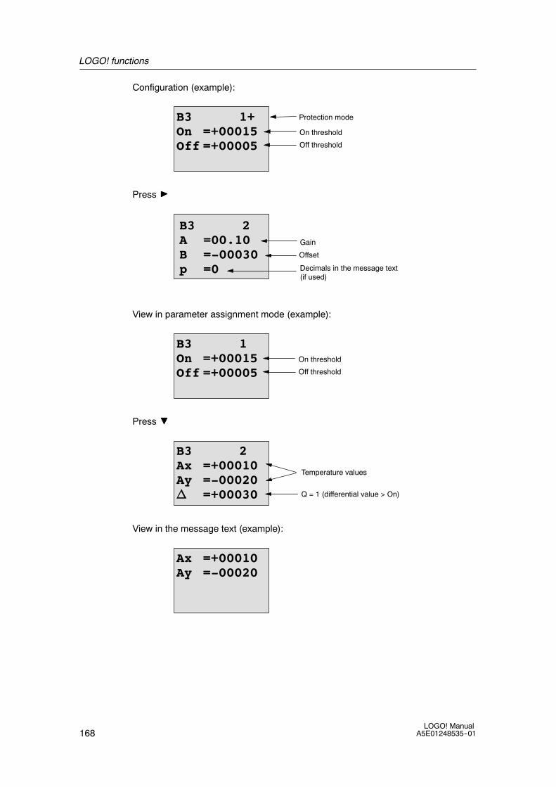
LOGO! functions
168LOGO! Manual
A5E01248535--01
Configuration (example):
B3 1+On =+00015Off =+00005
Protection mode
On threshold
Off threshold
Press
Decimals in the message text(if used)
B3 2A =00.10B =-00030p =0
Offset
Gain
View in parameter assignment mode (example):
B3 1On =+00015Off =+00005
On threshold
Off threshold
Press
B3 2Ax =+00010Ay =-00020n =+00030 Q = 1 (differential value > On)
Temperature values
View in the message text (example):
Ax =+00010Ay =-00020

LOGO! functions
169LOGO! ManualA5E01248535--01
Reducing the input response of the analog comparator
You can selectively delay the output of an analog comparator by means of the”On-delay” and ”Off-delay” special functions. With on-delay, output Q is only set ifthe pulse width of the triggering signal at input Trg (=analog comparator output) islonger than the on-delay time.
Using this method, you will obtain a virtual hysteresis and reduce the inputresponse to short signals.
Function block diagram
Q1
AI
nA
AI
AI1
AI2
B1
B2
B3
Analog comparator
On-delay
Off-delay

LOGO! functions
170LOGO! Manual
A5E01248535--01
4.4.19 Analog watchdog
Short description
This special function saves the process variable of an analog input to memory, andsets the output when the output variable exceeds or drops below this stored valueplus a configurable offset.
Symbol in LOGO! Wiring DescriptionInput En A positive edge (0 to 1 transition) at input En
saves the analog value at input Ax (”Aen”) tomemory and starts monitoring of the analogrange Aen --n2 to Aen+ n1
Input Ax You apply the analog signal to be monitored atinput Ax.
Use the analog inputs AI1...AI8 (*), the analogflags AM1...AM6, the block number of afunction with analog output, or the analogoutputs AQ1 and AQ2.
Parameter A: GainRange of values:¦10.00
B: Zero offsetRange of values: ¦10,000
n1:Difference value above Aen:on/off thresholdRange of values: 0--20,000
n2:Difference value belowAen: on/off thresholdRange of values: 0--20,000
p: Number of decimalsRange of values:0, 1, 2, 3
Output Q Q is set/reset, depending on the stored analogvalue and the offset.
* AI1...AI8: 0...10 V corresponds with 0...1000 (internal value).
Gain and offset parameters
For more information on gain and offset parameters, refer to Chapter 4.3.6.
Parameters Delta1 and Delta2
The Delta1 and Delta2 parameters can be provided by the actual value of anotheralready--programmed function. You can use the actual value of the followingfunctions:
• Analog comparator (actual value Ax - Ay, see Chapter 4.4.18)• Analog threshold trigger (actual value Ax, see Chapter 4.4.16)• Analog amplifier (actual value Ax, see Chapter 4.4.20)• Analog multiplexer (actual value AQ, see Chapter 4.4.26)• Analog ramp (actual value AQ, see Chapter 4.4.27)• Analog math (actual value AQ, see Chapter 4.4.30)• PI controller (actual value AQ, see Chapter 4.4.28)• Up/down counter (actual value Cnt, see Chapter 4.4.13)Select the required function by the block number.
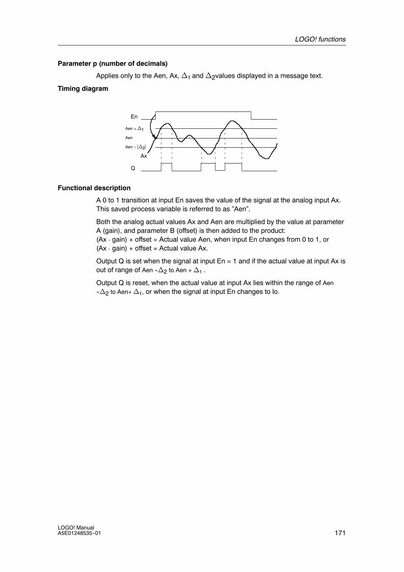
LOGO! functions
171LOGO! ManualA5E01248535--01
Parameter p (number of decimals)
Applies only to the Aen, Ax, n1 and n2values displayed in a message text.
Timing diagram
Q
Aen + n1
Ax
En
Aen -- jn2j
Aen
Functional description
A 0 to 1 transition at input En saves the value of the signal at the analog input Ax.This saved process variable is referred to as ”Aen”.
Both the analog actual values Ax and Aen are multiplied by the value at parameterA (gain), and parameter B (offset) is then added to the product:(Ax ¡ gain) + offset = Actual value Aen, when input En changes from 0 to 1, or(Ax ¡ gain) + offset = Actual value Ax.
Output Q is set when the signal at input En = 1 and if the actual value at input Ax isout of range of Aen --n2 to Aen + n1 .
Output Q is reset, when the actual value at input Ax lies within the range of Aen--n2 to Aen+ n1, or when the signal at input En changes to lo.
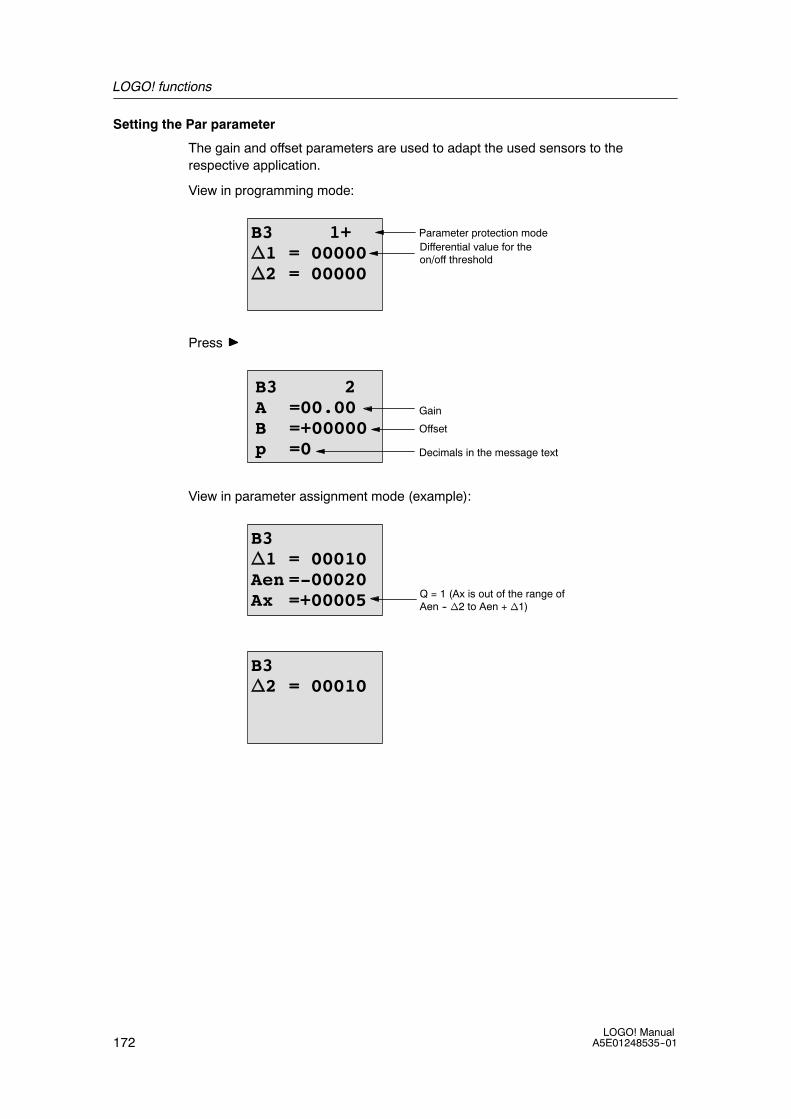
LOGO! functions
172LOGO! Manual
A5E01248535--01
Setting the Par parameter
The gain and offset parameters are used to adapt the used sensors to therespective application.
View in programming mode:
B3 1+n1 = 00000n2 = 00000
Parameter protection modeDifferential value for theon/off threshold
Press
Decimals in the message text
B3 2A =00.00B =+00000p =0
Offset
Gain
View in parameter assignment mode (example):
B3n1 = 00010Aen =-00020Ax =+00005 Q = 1 (Ax is out of the range of
Aen -- n2 to Aen + n1)
B3n2 = 00010
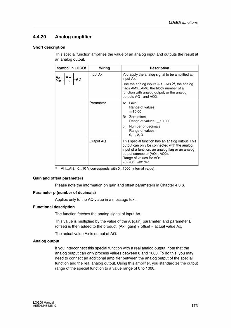
LOGO! functions
173LOGO! ManualA5E01248535--01
4.4.20 Analog amplifier
Short description
This special function amplifies the value of an analog input and outputs the result atan analog output.
Symbol in LOGO! Wiring Description
Input Ax You apply the analog signal to be amplified atinput Ax.
Use the analog inputs AI1...AI8 (*), the analogflags AM1...AM6, the block number of afunction with analog output, or the analogoutputs AQ1 and AQ2.
Parameter A: GainRange of values:¦10.00
B: Zero offsetRange of values: ¦10,000
p: Number of decimalsRange of values:0, 1, 2, 3
Output AQ This special function has an analog output! Thisoutput can only be connected with the analoginput of a function, an analog flag or an analogoutput connector (AQ1, AQ2).Range of values for AQ:--32768...+32767
* AI1...AI8: 0...10 V corresponds with 0...1000 (internal value).
Gain and offset parameters
Please note the information on gain and offset parameters in Chapter 4.3.6.
Parameter p (number of decimals)
Applies only to the AQ value in a message text.
Functional description
The function fetches the analog signal of input Ax.
This value is multiplied by the value of the A (gain) parameter, and parameter B(offset) is then added to the product: (Ax ¡ gain) + offset = actual value Ax.
The actual value Ax is output at AQ.
Analog output
If you interconnect this special function with a real analog output, note that theanalog output can only process values between 0 and 1000. To do this, you mayneed to connect an additional amplifier between the analog output of the specialfunction and the real analog output. Using this amplifier, you standardize the outputrange of the special function to a value range of 0 to 1000.

LOGO! functions
174LOGO! Manual
A5E01248535--01
Scaling an analog input value
You can influence the analog input value of a potentiometer by interconnecting ananalog input with an analog amplifier and an analog flag.
• Scale the analog value at the analog amplifier for further use.
• Connect, for example, the time base for parameter T of a time function (e.g.On-/Off-delay, Chapter 4.4.3) or the on and/or off limit specification of anup/down counter (Chapter 4.4.13) to the scaled analog value.
For more information with programming examples refer to the online help forLOGO!Soft Comfort.
Setting the Par parameter
The gain and offset parameters are used to adapt the sensors to the relevantapplication.
View in programming mode (example):
Decimals in the message text
B3 +A =02.50B =-00300p =0
Offset
Gain
View in parameter assignment mode (example):
B3A =02.50B =-00300AQ =-00250
4.4.21 Latching relay
Short description
Input S sets output Q, input R resets output Q again.
Symbol in LOGO! Wiring Description
Input S You set output Q with a signal at input S.
Input R You reset output Q with a signal at input R. If SandR = 1, the output is reset.
Parameter Retentivity:/ = No retentivityR = The status is retentive.
Output Q Q is set with a signal at input S, and reset witha signal at input R.
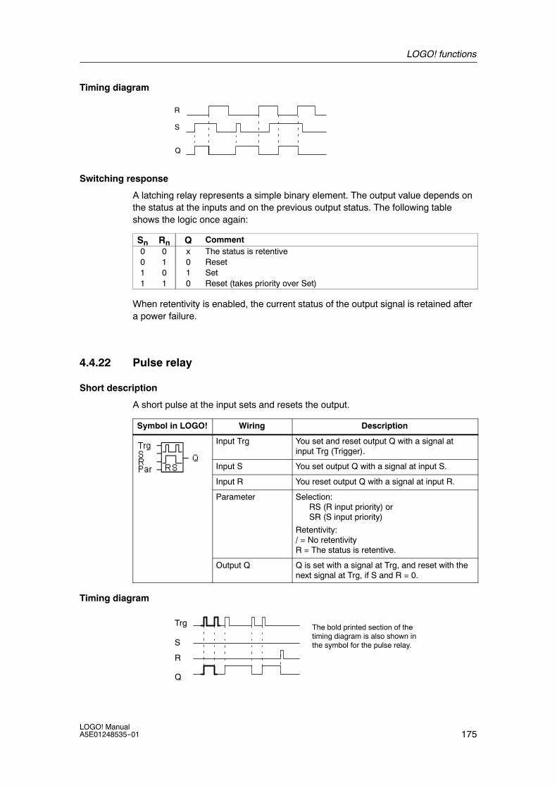
LOGO! functions
175LOGO! ManualA5E01248535--01
Timing diagram
S
R
Q
Switching response
A latching relay represents a simple binary element. The output value depends onthe status at the inputs and on the previous output status. The following tableshows the logic once again:
Sn Rn Q Comment0 0 x The status is retentive0 1 0 Reset1 0 1 Set1 1 0 Reset (takes priority over Set)
When retentivity is enabled, the current status of the output signal is retained aftera power failure.
4.4.22 Pulse relay
Short description
A short pulse at the input sets and resets the output.
Symbol in LOGO! Wiring Description
Input Trg You set and reset output Q with a signal atinput Trg (Trigger).
Input S You set output Q with a signal at input S.
Input R You reset output Q with a signal at input R.
Parameter Selection:RS (R input priority) orSR (S input priority)
Retentivity:/ = No retentivityR = The status is retentive.
Output Q Q is set with a signal at Trg, and reset with thenext signal at Trg, if S and R = 0.
Timing diagram
Trg
Q
R
The bold printed section of thetiming diagram is also shown inthe symbol for the pulse relay.S
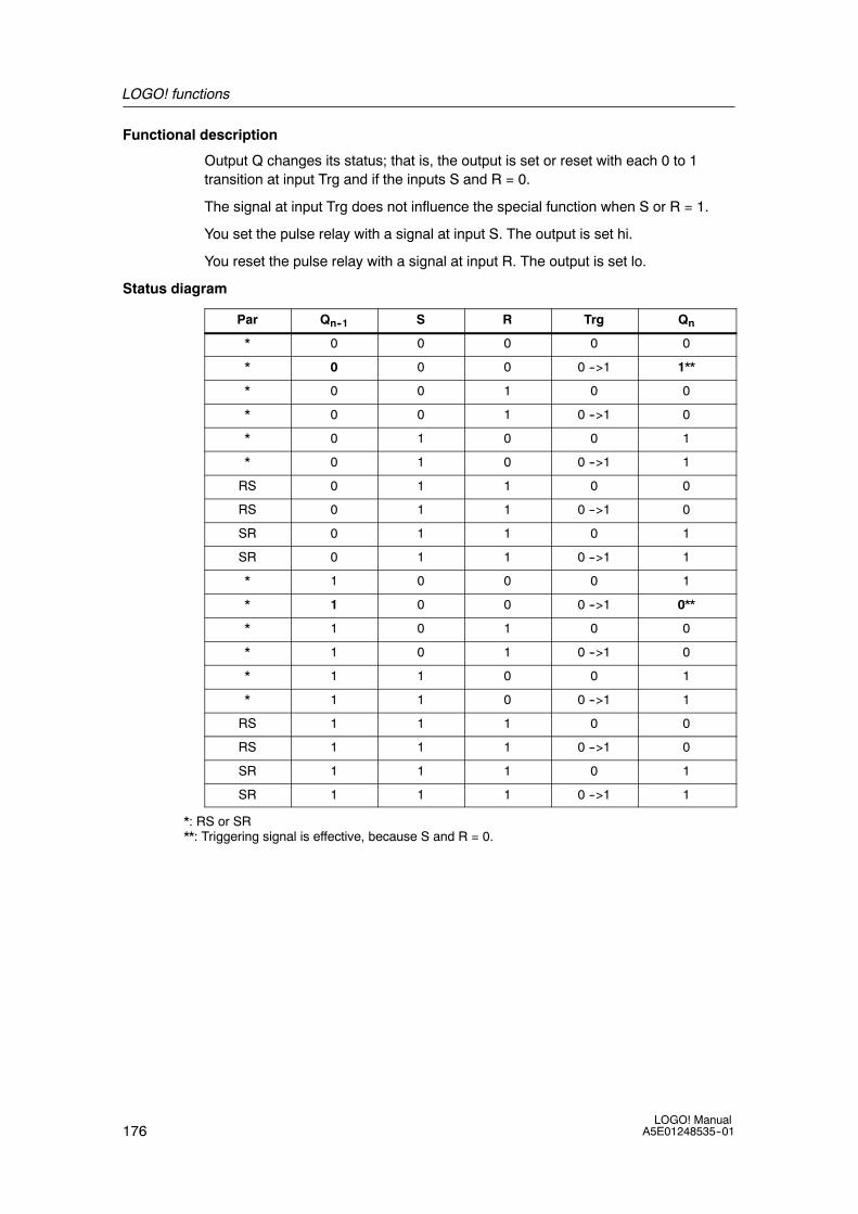
LOGO! functions
176LOGO! Manual
A5E01248535--01
Functional description
Output Q changes its status; that is, the output is set or reset with each 0 to 1transition at input Trg and if the inputs S and R = 0.
The signal at input Trg does not influence the special function when S or R = 1.
You set the pulse relay with a signal at input S. The output is set hi.
You reset the pulse relay with a signal at input R. The output is set lo.
Status diagram
Par Qn--1 S R Trg Qn
* 0 0 0 0 0
* 0 0 0 0 -->1 1**
* 0 0 1 0 0
* 0 0 1 0 -->1 0
* 0 1 0 0 1
* 0 1 0 0 -->1 1
RS 0 1 1 0 0
RS 0 1 1 0 -->1 0
SR 0 1 1 0 1
SR 0 1 1 0 -->1 1
* 1 0 0 0 1
* 1 0 0 0 -->1 0**
* 1 0 1 0 0
* 1 0 1 0 -->1 0
* 1 1 0 0 1
* 1 1 0 0 -->1 1
RS 1 1 1 0 0
RS 1 1 1 0 -->1 0
SR 1 1 1 0 1
SR 1 1 1 0 -->1 1
*: RS or SR**: Triggering signal is effective, because S and R = 0.

LOGO! functions
177LOGO! ManualA5E01248535--01
Depending on your configuration, either input R takes priority over input S ( input Sis not effective when R = 1), or vice versa (input R is not effective when S = 1).
After a power failure, the pulse relay and output Q are reset if you have notenabled retentivity.
View in programming mode:
B29 RPar=RS
B29 RPar=SR
PressB orY
This special function is not available in parameter assignment mode.
Note
If Trg = 0 and Par = RS, the special function ”Pulse relay” corresponds with thespecial function ”Latching relay” (see Chapter 4.4.21).
4.4.23 Message texts
Short description
With the message text function block, you can configure a message that includestext and other parameters for LOGO! to display in RUN mode.
You can configure simple message texts from the LOGO! Display. LOGO!SoftComfort provides an extended set of features for message texts: bar graphrepresentation of data, names for digital I/O states and more. Refer to theLOGO!Soft Comfort documentation for information on these features.
Global Message Text Settings
You configure global parameters that apply to all message texts from the MsgConfig selections on the Programming menu:
• Analog Time: refresh rate in milliseconds that specifies how frequently analoginputs in message texts are updated
• Tick time: frequency at which message texts scroll on and off the displayThere are two ways that a message text can tick on and off the screen: line byline, or character by character, which are described in more detail below. A lineof a text message, or each character of a text message in turn will tick on andoff the LOGO! Display based on the tick time. For a message that ticks line byline, the actual tick time is ten times the configured tick time. For messages thattick character by character, the actual tick time is the configured tick time.

LOGO! functions
178LOGO! Manual
A5E01248535--01
• CharSets: The primary and secondary character sets from which you canconfigure message texts. CharSet1 and CharSet2 can be any of the supportedcharacter sets for LOGO!:
Character Setin LOGO!
CommonName
Supports Languages Internet Reference
ISO8859--1 Latin--1 English, German,Italian, Spanish(partly), Dutch (partly)
http://en.wikipedia.org/wiki/ISO/IEC_8859--1
ISO8859--5 Cyrillic Russian http://en.wikipedia.org/wiki/ISO/IEC_8859--5
ISO8859--9 Latin--5 Turkish http://en.wikipedia.org/wiki/ISO/IEC_8859--9
ISO8859--16 Latin--10 French http://en.wikipedia.org/wiki/ISO/IEC_8859--16
GB--2312 Chinese Chinese http://en.wikipedia.org/wiki/GB2312
• Current Character Set: which character set is selected for the display ofmessage texts
Of the fifty possible message texts that you can configure, you can select anynumber of them to be from the first language and any number from the secondlanguage. For example, you could configure fifty message text function blocks thathave a single message text for Character Set 1. Alternatively, you could configuretwenty--five message text function blocks, each of which has two message texts:one for Character Set 1 and one for Character Set 2. Any combination is valid suchthat the total does not exceed fifty.
Within a single message text, the text must be from one character set. You can editmessage texts in any of the supported character sets from LOGO!Soft Comfort.From the LOGO! Basic Module, you can only edit text using characters from theISO8859--1 character set.
The language and therefore character set of a message text is independent of thelanguage setting for the LOGO! display menus. They can be different.
Chinese Character Set
The LOGO! Basic module and LOGO! TD support the Chinese character set(GB--2312) for the People’s Republic of China. The devices use Microsoft Windowsencoding for this character set. The Windows encoding allows the devices todisplay the same characters as shown in the LOGO!Soft Comfort message texteditor when you are using a Chinese emulator or a Chinese version of MicrosoftWindows.
The Chinese character set requires a Chinese version of Windows or a Chineseemulator to properly display Chinese characters in the LOGO!Soft Comfortmessage text editor. You must start the Chinese emulator before you open the themessage text function block in LOGO!Soft Comfort.

LOGO! functions
179LOGO! ManualA5E01248535--01
Programming Global Message Text Parameters
-->
Press
Select digit position to modify.(You cannot modify the last twodigits.)
Pressor
Pressor
Set theAnalogRefreshTime
EditClear PrgPassword>Msg Config
>Analog TimeTick timeCharSetsCurrCharSet
100ms
Set.1s.....1s
zzzzzzzl
Step through values of 100, 200,400, 800 or 1000 ms to increaseor decrease the analog inputrefresh time. LOGO! updates thevalue and cursor positionbetween .1s and 1s to show yourcurrent selection.
00200msAnalog Time>Tick timeCharSetsCurrCharSet
Analog TimeTick time>CharSetsCurrCharSet
Analog TimeTick timeCharSets>CurrCharSet
ISO8859-1ISO8859-5ISO8859-9ISO8859-16GB-2312
Set the CharSet1 orCharSet2 selection
PressOK
PressOK
Press
Press
PressOK
PressOK
PressOK
Pressor
Pressor
Set theTick Time
SelectCharacterSets
SelectCurrentCharacterSet
Select value from 0 to 9 for thecurrent position. Minimum ticktime is 100 ms. Maximum ticktime is 10000 ms.
>CharSet1CharSet2 Press
OK
Pressor
Select betweenCharSet1 andCharSet2
>CharSet1CharSet2 Press
orSelect CharSet1 or CharSet2for the current character set
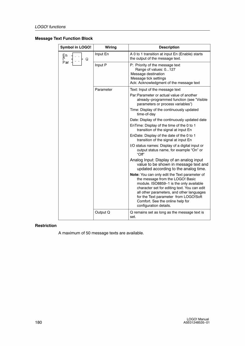
LOGO! functions
180LOGO! Manual
A5E01248535--01
Message Text Function Block
Symbol in LOGO! Wiring Description
Input En A 0 to 1 transition at input En (Enable) startsthe output of the message text.
Input P P: Priority of the message textRange of values: 0...127
Message destinationMessage tick settingsAck: Acknowledgment of the message text
Parameter Text: Input of the message text
Par:Parameter or actual value of anotheralready--programmed function (see ”Visibleparameters or process variables”)
Time: Display of the continuously updatedtime-of-day
Date: Display of the continuously updated date
EnTime: Display of the time of the 0 to 1transition of the signal at input En
EnDate: Display of the date of the 0 to 1transition of the signal at input En
I/O status names: Display of a digital input oroutput status name, for example “On” or“Off”
Analog Input: Display of an analog inputvalue to be shown in message text andupdated according to the analog time.
Note: You can only edit the Text parameter ofthe message from the LOGO! Basicmodule. ISO8859--1 is the only availablecharacter set for editing text. You can editall other parameters, and other languagesfor the Text parameter from LOGO!SoftComfort. See the online help forconfiguration details.
Output Q Q remains set as long as the message text isset.
Restriction
A maximum of 50 message texts are available.

LOGO! functions
181LOGO! ManualA5E01248535--01
Functional description
When LOGO! is in RUN mode, LOGO! displays the message text that you haveconfigured along with its parameter values upon a 0 to 1 transition of the signal atinput En.
Based on your setting for the message destination, the message text displays onthe LOGO! Display, the LOGO! TD, or both.
If you use flag M27 in your circuit program, then if M27=0 (low) then LOGO!displays the message text only if it is from the primary character set (Character Set1). If M27=1 (high), then LOGO! displays the message text only if is from thesecondary character set (Character Set 2). (See the M27 flag description in section4.1).
If you have configured message ticking, the message will tick on and off the displayaccording to your specifications, either a character at a time, or a line at a time.
If acknowledgment is disabled (Ack = Off), the message text is hidden when thestatus of the signal at input En changes from 1 to 0.
If acknowledgment is enabled (Ack = On) and the status of the signal at input Enchanges from 1 to 0, the message text is output until it is acknowledged with OK.When En = 1, you cannot acknowledge the message text.
When multiple message text functions are triggered with En=1, LOGO! displays themessage text with the highest priority (0 = lowest, 127 = highest). This also meansthat LOGO! displays a newly activated message text only if its priority is higherthan that of previously activated message texts.
After a message text is disabled or acknowledged, the function automaticallyshows the previously active message text that takes the highest priority.
You can change the view and the message texts by pressing the keys and .
Example
This is how two message texts could be shown:
Display field of LOGO! in RUN mode
Date and current time-of-day(only for versions with real-timeclock).2003-01-27
Mo 09:00
Key
Motor 23000hoursMAINTENANCE!
Example: Message text withpriority 10
Motor 5STOP AT10:12!!Action!!
Example: Message text withpriority 30
Press
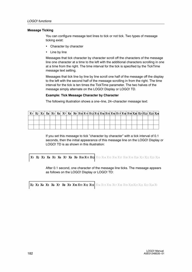
LOGO! functions
182LOGO! Manual
A5E01248535--01
Message Ticking
You can configure message text lines to tick or not tick. Two types of messageticking exist:
• Character by character
• Line by line
Messages that tick character by character scroll off the characters of the messageline one character at a time to the left with the additional characters scrolling in oneat a time from the right. The time interval for the tick is specified by the TickTimemessage text setting.
Messages that tick line by line by line scroll one half of the message off the displayto the left with the second half of the message scrolling in from the right. The timeinterval for the tick is ten times the TickTime parameter. The two halves of themessage simply alternate on the LOGO! Display or LOGO! TD.
Example: Tick Message Character by Character
The following illustration shows a one--line, 24--character message text:
If you set this message to tick ”character by character” with a tick interval of 0.1seconds, then the initial appearance of this message line on the LOGO! Display orLOGO! TD is as shown in this illustration:
After 0.1 second, one character of the message line ticks. The message appearsas follows on the LOGO! Display or LOGO! TD:

LOGO! functions
183LOGO! ManualA5E01248535--01
Example: Tick Message Line by Line
The following example uses the same message configuration as the previousexample:
If you set this message to tick ”line by line” with a tick interval of 0.1 seconds, thenthe initial appearance of this message on the LOGO! Display or LOGO! TD is theleft half of the message as shown in this illustration:
After 1 second (10 x 0.1 second), the message ticks to show the right half of themessage as shown in this illustration:
The screen display alternates between the two message halves every second.
You can configure each individual line of a message text to tick or not tick. The”character by character” or ”line by line” setting applies to all lines that youconfigure to tick.
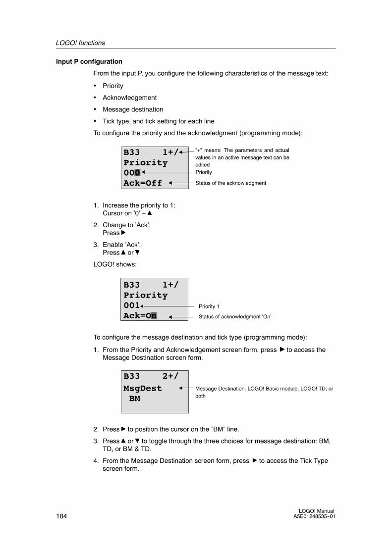
LOGO! functions
184LOGO! Manual
A5E01248535--01
Input P configuration
From the input P, you configure the following characteristics of the message text:
• Priority
• Acknowledgement
• Message destination
• Tick type, and tick setting for each line
To configure the priority and the acknowledgment (programming mode):
Priority
Status of the acknowledgment
”+” means: The parameters and actualvalues in an active message text can beedited
B33 1+/Priority000Ack=Off
1. Increase the priority to 1:Cursor on ’0’ +
2. Change to ’Ack’:Press
3. Enable ’Ack’:Press or
LOGO! shows:
B33 1+/Priority001Ack=On
Priority 1
Status of acknowledgment ’On’
To configure the message destination and tick type (programming mode):
1. From the Priority and Acknowledgement screen form, press to access theMessage Destination screen form.
MsgDestBM
Message Destination: LOGO! Basic module, LOGO! TD, orboth
B33 2+/
2. Press to position the cursor on the ”BM” line.
3. Press or to toggle through the three choices for message destination: BM,TD, or BM & TD.
4. From the Message Destination screen form, press to access the Tick Typescreen form.

LOGO! functions
185LOGO! ManualA5E01248535--01
TickTypeCh by Ch
Tick Type: Character by Character (Ch byCh) or Line by Line (Ln by Ln)
B33 3+/
5. If your message text has lines that tick, press to position the cursor on the ”Chby Ch” line and then press or to select either ”Ch by Ch” or ”Ln by Ln” forthe TickType.
6. From the Tick T ype screen, press to enable or disable ticking for each line ofthe message text. LOGO! displays the following screen form:
1 = No2 = No
Tick settings:No: Line does not tickYes: Line does tick
B33 4+/
7. Press or to choose between ”No” and ”Yes” to define whether line 1 ticks.
8. Press to move the cursor to the second line, and press or to choosebetween ”No” and ”Yes” for line 2. From the last line press to go to the screenfrom for lines 3 and 4. Configure line ticking for lines 3 and 4 in the same way asfor lines 1 and 2.
3 = No4 = No
Tick settings:No: Line does not tickYes: Line does tick
B33 5+/
9. Press OK to confirm the complete message text configuration.
Visible parameters or process variables
The following parameters or process variables can be displayed in a message text,as either numerical values or bar--graph representations of values:
Special function Parameter or process variable visible ina message text
Timers
On-delay T, Ta
Off-delay T, Ta
On-/Off-delay Ta, TH, TL
Retentive on-delay T, Ta
Wiping relay(pulse output)
T, Ta
Edge triggeredwiping relay
Ta, TH, TL
Asynchronous pulse generator Ta, TH, TL

LOGO! functions
186LOGO! Manual
A5E01248535--01
Special function Parameter or process variable visible ina message text
Random generator TH, TL
Stairway lighting switch Ta, T, T!, T!L
Multiple function switch Ta, T, TL, T!, T!L
Weekly timer 3*on/off/day
Yearly timer On, Off
Counter
Up/down counter Cnt, On, Off
Hours counter MI, Q, OT
Threshold trigger fa, On, Off, G_T
Analog
Analog threshold trigger On, Off, A, B, Ax
Analog differential trigger On, n, A, B, Ax, Off
Analog comparator On, Off, A, B, Ax, Ay, nA
Analog value monitoring n, A, B, Ax, Aen
Analog amplifier A, B, Ax
Analog multiplexer V1, V2, V3, V4, AQ
Analog ramp L1, L2, MaxL, StSp, Rate, A, B, AQ
PI controller SP, Mq, KC, TI, Min, Max, A, B, PV, AQ
Analog math V1, V2, V3, V4, AQ
PWM (Pulse Width Modulator) A, B, T, Ax amplified
Miscellaneous
Latching relay --
Pulse relay --
Message texts --
Softkey On/Off
Shift register --
For timers, a message text can also display the remaining time. “Remaining time”refers to how much time of the parameter setting remains.
Bar graphs can be either horizontal or vertical representations of the current oractual value scaled between the minimum and maximum value. For moreinformation on configuring and displaying bar graphs in message texts, refer to theLOGO!Soft Comfort online help.
LOGO! functions
187LOGO! ManualA5E01248535--01
Editing message texts
Only simple message texts can be edited from the LOGO! Basic module. Textmessages created in LOGO!Soft Comfort that make use of new features such asbar graphs, I/O status names, and others can not be edited from the LOGO! Basicmodule.
Also, you cannot edit message texts from the LOGO! Basic module that containany of the following parameters:
• Par
• Time
• Date
• EnTime
• EnDate
You can only edit such message texts from LOGO!Soft Comfort.
Changing parameters in the active message text
When the message text is active, press ESC to select the editing mode.
Note
You must keep the ESC key pressed for at least one second
Press and to select the relevant parameter. Press OK to change theparameter. Use the and keys to edit a parameter.
Confirm your changes with OK. You can now edit further parameters in themessage text (if any exist). Press ESC to exit editing mode.
Key input simulation in the active message text
You can enable the four cursor keys C Y, C ", C B and C A in an active messagetext by pressing ESC plus the relevant cursor key.

LOGO! functions
188LOGO! Manual
A5E01248535--01
Setting the Par parameter
View in programming mode:
..
..
..
..
Parameter assignment
screen form for Par
Press to select a line for the message text.
Press and to select the letter to be displayed in the text. To move the cursorfrom one position to the other, press and .
The list of available characters is the same as for the circuit program name. Thecharacter set is found in Chapter 3.7.4. When you enter message text from theLOGO! Basic module, you can only enter characters from the ISO8859--1 characterset. To enter text from another language, you must enter the text in LOGO!SoftComfort.
Note that the number of characters per line of message text can be greater thanthe number of character positions on the LOGO! Display.
Press OK to confirm your changes, and press ESC to exit the editing mode.

LOGO! functions
189LOGO! ManualA5E01248535--01
4.4.24 Softkey
Short description
This special function has the effect of a mechanical pushbutton or switch.
Symbol in LOGO! Wiring Description
EnPar Q
Input En Output Q is set with a 0 to 1 transition of thesignal at input En (Enable), and if ’Switch=On’was confirmed in parameter assignment mode.
Parameter Programming mode:Selecting the function for pushbutton action forthe duration of one cycle, or for switchingaction.
Start: On or off state, initialized at the first startof the program if retentivity is disabled.
Retentivity:/ = No retentivityR = The status is retentive.
Parameter assignment mode (RUN mode):Switch: Switches the momentary pushbutton(switch) on or off.
Output Q Switches on if En=1 and Switch=On wasconfirmed with OK.
Factory setting
The default parameter setting is switching action.
Timing diagram
Switch
En
Q
Functional description
In parameter assignment mode, the output is set with a signal at input En, if the’’Switch’ parameter is set to ’On’ and confirmed with OK. Whether the function wasconfigured for pushbutton or switching action is of no concern here.
The output is reset to ’0’ in the following three cases:
• After a 1 to 0 transition at input En
• When the function was configured for momentary pushbutton action, and onecycle has expired since it was switched on
• When the position ’Off’ was selected at the ’Switch’ parameter and confirmedwith OK in parameter assignment mode
If retentivity is not set, output Q is initialized after a power failure according to yourconfiguration at the ”Start” parameter.

LOGO! functions
190LOGO! Manual
A5E01248535--01
Setting the Par parameter
View in programming mode (example):
1. Select the ’Softkey’ function.
2. Select input En and confirm with OK. The cursor is now positioned below ’Par’.
3. Change to the input mode of ’Par’:Confirm with OK(the cursor is now positioned to ’On’)
B33 +/On=Start=On
The function is set for ’momentarypushbutton’ action
The status is not retentive
Q is set in the first cycle after theprogram start
To change ’Par’ to ’Switch’ action and the initialization status after the programstart:
4. To select ’Momentary pushbutton’ or ’Switch’ action:
Press or
B33 +/On/OffStart=On
’Switch’ function
The status is not retentive
Q is set in the first cycle after theprogram start
5. To change to the start state:Press or
6. To change the start state:
Press or
B33 +/On/OffStart=Off
’Switch’function
The status is not retentive
Q is reset in the init cycle after theprogram start
7. Confirm your entries with
OK

LOGO! functions
191LOGO! ManualA5E01248535--01
View in parameter assignment mode (example):
Here, you can set or reset the ’Switch’ parameter (On/Off). When in RUN, LOGO!shows the following display:
B33
Switch=Off The pushbutton/switch here is switched off
Let us assume you want to set ’Switch’ (On).
1. Change to the editing mode:Confirm with OK(the cursor is now positioned on ’Off’)
2. To change from ’Off’ to ’On’:Press or
3. Confirm your entries with
Press OK
B33
Switch=OnThe momentary pushbutton/switchis here switched on

LOGO! functions
192LOGO! Manual
A5E01248535--01
4.4.25 Shift register
Short description
You can use the shift register function to read the value of an input and to shift itsbits left or right. The output value corresponds with the configured shift register bit.The shifting direction can be changed at a special input.
Symbol in LOGO! Wiring Description
Input In Input read at the start of the function.
Input Trg A positive edge (0 to 1 transition) at input Trg(Trigger) starts the special function.1 to 0 transitions are irrelevant.
Input Dir The signal at input Dir determines the shiftingdirection for the shift register bits S1...S8:
Dir = 0: Shift up (S1 >> S8)
Dir = 1: Shift down (S8 >> S1)
Parameter Shift register bit that determines the value atoutput Q.
Possible settings:S1 ... S8
Retentivity:/ = No retentivityR = The status is retentive.
Output Q The output value corresponds with theconfigured shift register bit.
Functional description
The function reads the value at input In with a positive edge (0 to 1 transition) atinput Trg (Trigger).
This value is applied to shift register bit S1 or S8, depending on the shiftingdirection:
• Shift up: The value at input In is set at S1; the previous value at S1 is shifted toS2; the previous value at S2 is shifted to S3 etc.
• Shift down: The value at input In is set at S8; the previous value at S8 is shiftedto S7; the previous value at S7 is shifted to S6 etc.
Output Q returns the value of the configured shift register bit.
If retentivity is disabled, the shift function restarts at S1 or S8 after a power failure.When enabled, retentivity always applies to all shift register bits.
Note
The special function shift register can be used only once in the circuit program.

LOGO! functions
193LOGO! ManualA5E01248535--01
Timing diagram
Trg
In
Q
Dir
S1 0 1 0 1 1 0 1S2 0 0 1 0 1 1 1S3 0 0 0 1 0 1 0S4 0 0 0 0 1 0 1S5 1 0 0 0 0 1 0S6 1 1 0 0 0 0 0S7 0 1 1 0 0 0 0S8 0 0 1 1 0 0 1
S4 = Q (example)
Shift up Shift down
Setting the Par parameter
View in programming mode:
Preset
Retentivity enabledB3 RQ=S8
Press
B3 RQ=S7
etc. You can select S8...S1.
This special function is not available in parameter assignment mode.
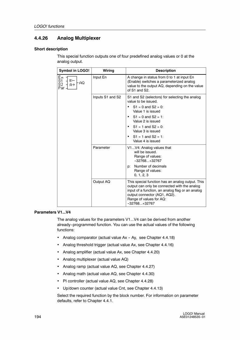
LOGO! functions
194LOGO! Manual
A5E01248535--01
4.4.26 Analog Multiplexer
Short description
This special function outputs one of four predefined analog values or 0 at theanalog output.
Symbol in LOGO! Wiring Description
Input En A change in status from 0 to 1 at input En(Enable) switches a parameterized analogvalue to the output AQ, depending on the valueof S1 and S2.
Inputs S1 and S2 S1 and S2 (selectors) for selecting the analogvalue to be issued.
• S1 = 0 and S2 = 0:Value 1 is issued
• S1 = 0 and S2 = 1:Value 2 is issued
• S1 = 1 and S2 = 0:Value 3 is issued
• S1 = 1 and S2 = 1:Value 4 is issued
Parameter V1...V4: Analog values thatwill be issued.Range of values:--32768...+32767
p: Number of decimalsRange of values:0, 1, 2, 3
Output AQ This special function has an analog output. Thisoutput can only be connected with the analoginput of a function, an analog flag or an analogoutput connector (AQ1, AQ2).Range of values for AQ:--32768...+32767
Parameters V1...V4
The analog values for the parameters V1...V4 can be derived from anotheralready--programmed function. You can use the actual values of the followingfunctions:
• Analog comparator (actual value Ax -- Ay, see Chapter 4.4.18)
• Analog threshold trigger (actual value Ax, see Chapter 4.4.16)
• Analog amplifier (actual value Ax, see Chapter 4.4.20)
• Analog multiplexer (actual value AQ)
• Analog ramp (actual value AQ, see Chapter 4.4.27)
• Analog math (actual value AQ, see Chapter 4.4.30)
• PI controller (actual value AQ, see Chapter 4.4.28)
• Up/down counter (actual value Cnt, see Chapter 4.4.13)
Select the required function by the block number. For information on parameterdefaults, refer to Chapter 4.4.1.
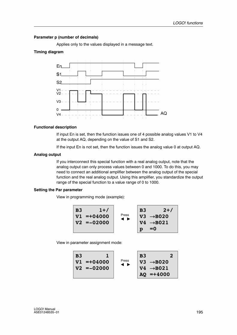
LOGO! functions
195LOGO! ManualA5E01248535--01
Parameter p (number of decimals)
Applies only to the values displayed in a message text.
Timing diagram
En
SS1
S2
AQ
V1
V3
V2
V40
Functional description
If input En is set, then the function issues one of 4 possible analog values V1 to V4at the output AQ, depending on the value of S1 and S2.
If the input En is not set, then the function issues the analog value 0 at output AQ.
Analog output
If you interconnect this special function with a real analog output, note that theanalog output can only process values between 0 and 1000. To do this, you mayneed to connect an additional amplifier between the analog output of the specialfunction and the real analog output. Using this amplifier, you standardize the outputrange of the special function to a value range of 0 to 1000.
Setting the Par parameter
View in programming mode (example):
B3 1+/V1 =+04000V2 =-02000
B3 2+/V3 !B020V4 !B021p =0
PressA "
View in parameter assignment mode:
B3 1V1 =+04000V2 =-02000
B3 2V3 !B020V4 !B021AQ =+4000
PressA "
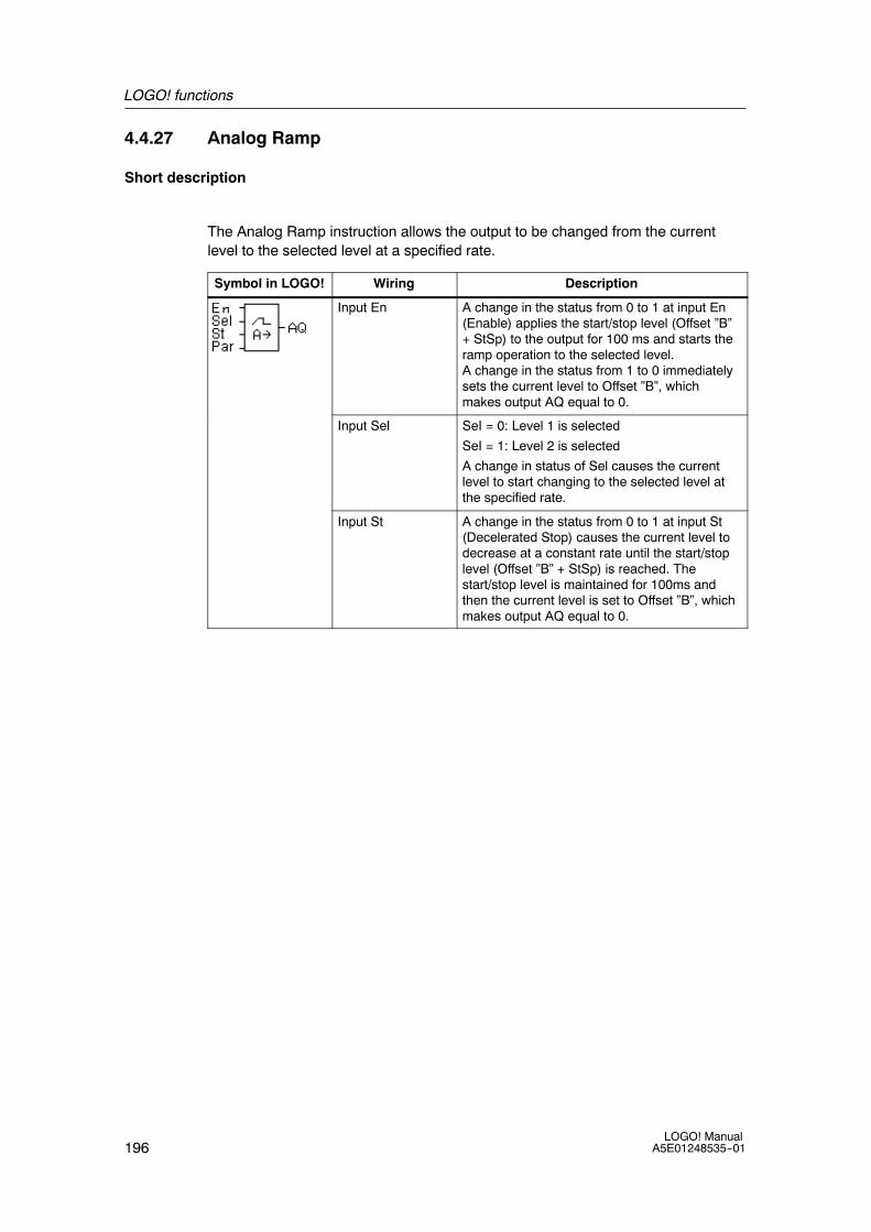
LOGO! functions
196LOGO! Manual
A5E01248535--01
4.4.27 Analog Ramp
Short description
The Analog Ramp instruction allows the output to be changed from the currentlevel to the selected level at a specified rate.
Symbol in LOGO! Wiring Description
Input En A change in the status from 0 to 1 at input En(Enable) applies the start/stop level (Offset ”B”+ StSp) to the output for 100 ms and starts theramp operation to the selected level.A change in the status from 1 to 0 immediatelysets the current level to Offset ”B”, whichmakes output AQ equal to 0.
Input Sel SeI = 0: Level 1 is selected
SeI = 1: Level 2 is selected
A change in status of Sel causes the currentlevel to start changing to the selected level atthe specified rate.
Input St A change in the status from 0 to 1 at input St(Decelerated Stop) causes the current level todecrease at a constant rate until the start/stoplevel (Offset ”B” + StSp) is reached. Thestart/stop level is maintained for 100ms andthen the current level is set to Offset ”B”, whichmakes output AQ equal to 0.
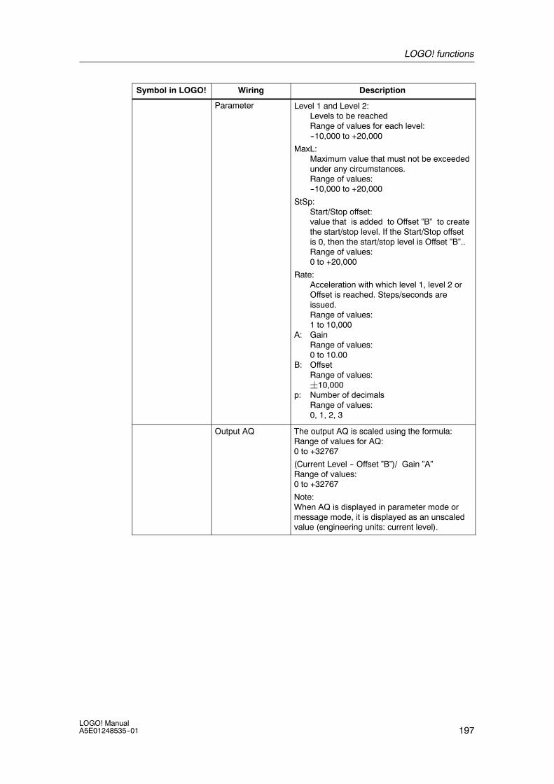
LOGO! functions
197LOGO! ManualA5E01248535--01
Symbol in LOGO! DescriptionWiring
Parameter Level 1 and Level 2:Levels to be reachedRange of values for each level:--10,000 to +20,000
MaxL:Maximum value that must not be exceededunder any circumstances.Range of values:--10,000 to +20,000
StSp:Start/Stop offset:value that is added to Offset ”B” to createthe start/stop level. If the Start/Stop offsetis 0, then the start/stop level is Offset ”B”..Range of values:0 to +20,000
Rate:Acceleration with which level 1, level 2 orOffset is reached. Steps/seconds areissued.Range of values:1 to 10,000
A: GainRange of values:0 to 10.00
B: OffsetRange of values:¦10,000
p: Number of decimalsRange of values:0, 1, 2, 3
Output AQ The output AQ is scaled using the formula:Range of values for AQ:0 to +32767
(Current Level -- Offset ”B”)/ Gain ”A”Range of values:0 to +32767
Note:When AQ is displayed in parameter mode ormessage mode, it is displayed as an unscaledvalue (engineering units: current level).
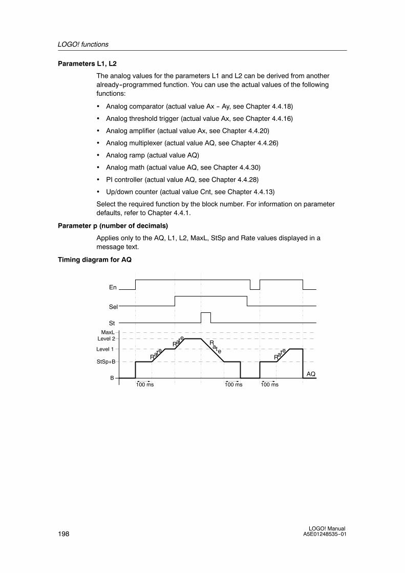
LOGO! functions
198LOGO! Manual
A5E01248535--01
Parameters L1, L2
The analog values for the parameters L1 and L2 can be derived from anotheralready--programmed function. You can use the actual values of the followingfunctions:
• Analog comparator (actual value Ax -- Ay, see Chapter 4.4.18)
• Analog threshold trigger (actual value Ax, see Chapter 4.4.16)
• Analog amplifier (actual value Ax, see Chapter 4.4.20)
• Analog multiplexer (actual value AQ, see Chapter 4.4.26)
• Analog ramp (actual value AQ)
• Analog math (actual value AQ, see Chapter 4.4.30)
• PI controller (actual value AQ, see Chapter 4.4.28)
• Up/down counter (actual value Cnt, see Chapter 4.4.13)
Select the required function by the block number. For information on parameterdefaults, refer to Chapter 4.4.1.
Parameter p (number of decimals)
Applies only to the AQ, L1, L2, MaxL, StSp and Rate values displayed in amessage text.
Timing diagram for AQ
En
Sel
Level 2
Level 1
Rate
Rate
Rate
Rate
St
StSp+B
100 ms 100 ms 100 ms
MaxL
BAQ

LOGO! functions
199LOGO! ManualA5E01248535--01
Functional description
If the input En is set, then the function sets the current level to StSp + Offset ”B” for100 ms.
Then, depending on the connection of Sel, the function runs from the level StSp +Offset ”B” to either level 1 or level 2 at the acceleration set in Rate.
If the input St is set, the function runs to a level of StSp + Offset ”B” at theacceleration set in Rate. Then the function holds the level at StSp + Offset ”B” for100 ms. After 100 ms, the level is set to Offset ”B”. The scaled value (output AQ) is0.
If the input St is set, the function can only be restarted after the inputs St and Enhave been reset.
If input Sel has been changed, depending on the connection of Sel, the functionruns from the current target level to the new target level at the rate that is specified.
If the input En is reset, the function immediately sets the current level to Offset ”B”.
The current level is updated every 100 ms. Note the relationship between outputAQ and the current level:
Output AQ = (current level -- Offset ”B” / Gain ”A”)
Note
For further information on analog value processing please refer to the online helpfor LOGO!Soft Comfort.
Setting the Par parameter
View in programming mode (example):
B3 1+/L1 =+04000L2 !B020
B3 2+/MaxL=+7000StSp=00222Rate=00500
PressA "
PressA "
Decimals in the message text
B3 3+/A =02.50B =-00300p =0
Offset
Gain
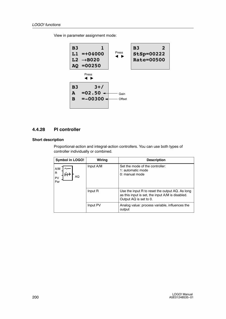
LOGO! functions
200LOGO! Manual
A5E01248535--01
View in parameter assignment mode:
B3 1L1 =+04000L2 !B020AQ =00250
B3 2StSp=00222Rate=00500
PressA "
PressA "
B3 3+/A =02.50B =-00300 Offset
Gain
4.4.28 PI controller
Short description
Proportional-action and integral-action controllers. You can use both types ofcontroller individually or combined.
Symbol in LOGO! Wiring Description
A/MR
PVPar
AQ
Input A/M Set the mode of the controller:1: automatic mode0: manual mode
Input R Use the input R to reset the output AQ. As longas this input is set, the input A/M is disabled.Output AQ is set to 0.
Input PV Analog value: process variable, influences theoutput
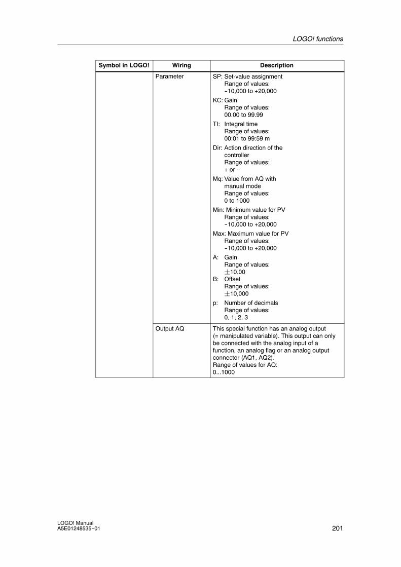
LOGO! functions
201LOGO! ManualA5E01248535--01
Symbol in LOGO! DescriptionWiring
Parameter SP: Set-value assignmentRange of values:--10,000 to +20,000
KC: GainRange of values:00.00 to 99.99
TI: Integral timeRange of values:00:01 to 99:59 m
Dir: Action direction of thecontrollerRange of values:+ or --
Mq: Value from AQ withmanual modeRange of values:0 to 1000
Min: Minimum value for PVRange of values:--10,000 to +20,000
Max: Maximum value for PVRange of values:--10,000 to +20,000
A: GainRange of values:¦10.00
B: OffsetRange of values:¦10,000
p: Number of decimalsRange of values:0, 1, 2, 3
Output AQ This special function has an analog output(= manipulated variable). This output can onlybe connected with the analog input of afunction, an analog flag or an analog outputconnector (AQ1, AQ2).Range of values for AQ:0...1000

LOGO! functions
202LOGO! Manual
A5E01248535--01
Parameters SP and Mq
The set--value SP and the value for Mq can be provided by anotheralready--programmed function. You can use the actual values of the followingfunctions:
• Analog comparator (actual value Ax -- Ay, see Chapter 4.4.18)
• Analog threshold trigger (actual value Ax, see Chapter 4.4.16)
• Analog amplifier (actual value Ax, see Chapter 4.4.20)
• Analog multiplexer (actual value AQ, see Chapter 4.4.26)
• Analog ramp (actual value AQ, see Chapter 4.4.27)
• Analog math (actual value AQ, see Chapter 4.4.30)
• PI controller (actual value AQ)
• Up/down counter (actual value Cnt, see Chapter 4.4.13)
Select the required function by the block number. For information on parameterdefaults, refer to Chapter 4.4.1.
Parameters KC, TI
Please note:
• If parameter KC has value 0, the ”P” function (proportional control) will not beexecuted.
• If parameter TI has value 99:59 m, the ”I” function (integral-action control) willnot be executed.
Parameter p (number of decimals)
Applies only to the PV, SP, Min and Max values displayed in a message text.

LOGO! functions
203LOGO! ManualA5E01248535--01
Timing diagram
The nature, manner and speed with which the AQ changes depend on theparameters KC and TI. Thus, the course of AQ in the diagram is merely anexample. A control action is continuous; therefore the diagram portrays just anextract.
1 2 3
A/M
R
Dir
AQMq
500 ms
Min
Max
PVSP
/+
/--
Q
1. A disturbance causes the PV to drop, as Dir is positioned upwards, AQincreases until PV corresponds again to SP.
2. A disturbance causes the PV to drop, as Dir is positioned downwards, AQdecreases until PV corresponds again to SP.It is not possible to change the direction (Dir) at runtime of the function. Thechange is shown here for illustrative purposes only.
3. As AQ is set to 0 by means of the input R, PV changes. This is based on thefact that PV increases, which on account of Dir = upwards causes AQ to drop.

LOGO! functions
204LOGO! Manual
A5E01248535--01
Functional description
If the input A/M is set to 0, then the special function issues output AQ with thevalue that you set with parameter Mq.
If the input A/M is set to 1, then automatic mode commences. As an integral sumthe value Mq is adopted, the controller function begins the calculations.
Note
For further information on the controller basics please refer to the online help forLOGO!Soft Comfort.
The updated value PV is used to calculate in the formulas:
Updated value PV = (PV ¡ gain) + offset
• If the updated value PV = SP, then the special function does not change thevalue of AQ.
• Dir = upwards (+) (timing diagram numbers 1. and 3.)
-- If the updated value PV > SP, then the special function reduces the value ofAQ.
-- If the updated value PV < SP, then the special function increases the valueof AQ.
• Dir = downwards (--) (timing diagram number 2.)
-- If the updated value PV > SP, then the special function increases the valueof AQ.
-- If the updated value PV < SP, then the special function reduces the value ofAQ.
With a disturbance, AQ continues to increase / decrease until the updated valuePV again corresponds to SP. The speed with which AQ changes depends on theparameters KC and TI.
If the input PV exceeds the parameter Max, then the updated value PV is set to thevalue of Max. If the PV falls short of the parameter Min, then the updated value PVis set to the value of Min.
If the input R is set to 1, then the AQ output is reset. As long as R is set, the inputA/M is disabled.
Sampling time
The sampling time is fixed at 500 ms.

LOGO! functions
205LOGO! ManualA5E01248535--01
Parameter sets
For more information and application examples with application-related parametersets for KC, TI and Dir refer to the online help for LOGO!Soft Comfort.
Setting the Par parameter
View in programming mode (example):
B3 1+/SP !B020
B3 2+/KC =10.00TI =01:00Dir=+
PressA "
PressA "
B3 4+/A =02.50B =-00300p =0
B3 2+/KC =10.00TI =01:00Dir=+
B3 3+/Mq !B021Min=-05000Max=+05000
PressA "
View in parameter assignment mode:
B3 1SP !B020PV = 0AQ =+0250
B3 2KC =10.00TI =01:00Dir=+
PressA "
PressA "
B3 4A =02.50B =-00300
B3 3Mq !B021Min=-05000Max=+05000
PressA "

LOGO! functions
206LOGO! Manual
A5E01248535--01
4.4.29 Pulse Width Modulator (PWM)
Short description
The Pulse Width Modulator (PWM) instruction modulates the analog input value Axto a pulsed digital output signal. The pulse width is proportional to the analog valueAx.
Symbol in LOGO! Wiring Description
Input Ax Analog signal to be modulated to a pulseddigital output signal.
Parameter A: GainRange of values: +-- 10.00
B: Zero offsetRange of values: +-- 10,000
T: Periodic time over which the digital outputis modulated
p: Number of decimalsRange of values: 0, 1, 2, 3
Output Q Q is set or reset for the proporition of each timeperiod according to the proportion of thestandardized value Ax to the analog valuerange.
Parameter T
Note the defaults of the T parameters listed in Chapter 4.3.2.
The periodic time T can be provided by the actual value of anotheralready--programmed function. You can use the actual value of the followingfunctions:
• Analog comparator (actual value Ax - Ay, see Chapter 4.4.18)
• Analog threshold trigger (actual value Ax, see Chapter 4.4.16)
• Analog amplifier (actual value Ax, see Chapter 4.4.20)
• Analog multiplexer (actual value AQ, see Chapter 4.4.26)
• Analog ramp (actual value AQ, see Chapter 4.4.27)
• Analog math (actual value AQ, see Chapter 4.4.30)
• PI controller (actual value AQ, see Chapter 4.4.28)
• Up/down counter (actual value Cnt, see Chapter 4.4.13).
Select the required function by the block number. The timebase is configurable. Forinformation on valid ranges and parameter defaults, refer to Chapter 4.4.1.
Parameters p (number of decimals)
Parameter p applies only to the display of the Ax value in a message text

LOGO! functions
207LOGO! ManualA5E01248535--01
Functional description
The function reads the value of the signal at the analog input Ax.This value is multiplied by the value of parameter A (gain). Parameter B (offset) isadded to the product, as follows:
(Ax * Gain) + Offset = Actual value Ax
The function block calculates the proportion of the actual value Ax to the range.The block sets the digital output Q high for the same proportion of the T (periodictime) parameter, and sets Q low for the remainder of the time period.
Examples with Timing Diagrams
The following examples show how the PWM instruction modulates a digital outputsignal from the analog input value:
1. An analog value of 500 (range 0...1000) as the value for Ax must be modulatedto a digital signal string. The user--defined T (periodic time) parameter is 4seconds. At the digital output of the PWM function the digital signal string is 2seconds high, 2 seconds low, 2 seconds high, 2 seconds low and continues inthat pattern as long as parameter En = high.
2. An analog value of 300 (range 0...1000) as the value for Ax must be modulatedto a digital signal string. The user--defined T (periodic time) parameter is 10seconds. At the digital output of the PWM function the digital signal string is 3seconds high, 7 seconds low, 3 seconds high, 7 seconds low and continues inthat pattern as long as parameter ”En” = high.

LOGO! functions
208LOGO! Manual
A5E01248535--01
Calculation rule
Q = 1, for (Ax -- Min)/ (Max -- Min) of time period T, when Min < Ax < MaxQ = 0, for PT -- [ (Ax -- Min) / (Max -- Min) ] of time period T.
Note: Ax in this calculation refers to the actual value Ax as calculated using theGain and Offset.
Setting the Par Parameter
The following illustration shows the view in programming mode that corresponds tothe first example:
B1 1+/Min=+00000Max=+01000A=+01.00
PressA "
B1 2+/B=+00000T=00:04sP=2
Use the and keys to navigate to the Min, Max, A, B, T and P parameters. Foreach digit of a value, use the and keys to scroll through value choices. Usethe key to navigate to the second screen from the last line of the first screen,and the key to navigate from the top line of the second screen to the first screen.Use the OK key to accept changes.
View in parameter assignment mode:
PressA "
B1 2B =+00000T =00:04s
B1 1Min=+00000Max=+01000A = 1.00

LOGO! functions
209LOGO! ManualA5E01248535--01
4.4.30 Analog math
Short description
The analog math block calculates the value AQ of an equation formed from theuser--defined operands and operators.
Symbol in LOGO! Wiring Description
Input En A change in the status from 0 to 1 at input En(Enable) enables the analog math functionblock.
Parameter V1: First operand valueV2: Second operand valueV3: Third operand valueV4: Fourth operand value
Op1: First operatorOp2: Second operatorOp3: Third operator
Pr1: Priority of first operationPr2: Priority of second operationPr3: Priority of third operation
Qen!0: 0: Reset value of AQ to 0 when En=01: Retain last value of AQ when En=0
p: Number of decimalsRange of values: 0, 1, 2, 3
Output AQ The output AQ is the result of the equationformed from the operand values and operators.AQ will be set to 32767 if a divide by 0 oroverflow occurs, and --32768 if a negativeoverflow (underflow) occurs.
Parameters V1...V4
The analog values for the parameters V1...V4 can be derived from anotheralready--programmed function. You can use the actual values of the followingfunctions:
• Analog comparator (actual value Ax -- Ay, see Chapter 4.4.18)
• Analog threshold trigger (actual value Ax, see Chapter 4.4.16)
• Analog amplifier (actual value Ax, see Chapter 4.4.20)
• Analog multiplexer (actual value AQ)
• Analog ramp (actual value AQ, see Chapter 4.4.27)
• Analog math (actual value AQ, see Chapter 4.4.30)
• PI controller (actual value AQ, see Chapter 4.4.28)
• Up/down counter (actual value Cnt, see Chapter 4.4.13).
Select the required function by the block number. For information on parameterdefaults, refer to Chapter 4.4.1.

LOGO! functions
210LOGO! Manual
A5E01248535--01
Parameters p (number of decimals)
Parameter p applies only to the display of Value1, Value2, Value3, Value4 and AQin a message text.
Functional Description
The analog math function combines the four operands and three operators to forman equation. The operator can be any one of the four standard operators: +, --, *, or/. For each operator, you must set a unique priority of High (H), Medium(M), orLow(L). The high operation will be performed first, followed by the mediumoperation, and then by the low operation. You must have exactly one operation ofeach priority. The operand values can reference another previously--definedfunction to provide the value.
The number of operand values is fixed at four and the number of operators is fixedat 3. If you need to use fewer operands, use constructions such as + 0 or * 1 to fillthe remaining parameters.
You can also configure the behavior of the function when the Enable parameterEn=0. The function block can either retain its last value, or be set to 0. If theparameter Qen!0 = 0, then the function sets AQ to 0 when En=0. If the parameterQen!0 = 1, then the function leaves AQ at its last value when En=0.
Possible errors: Zero division and overflow
If the analog math function block execution results in zero division or overflow, itsets internal bits that indicate the type of error that occurred. You can program ananalog math error detection function block in your circuit program to detect theseerrors, and to control the program behavior as needed. You program one analogmath error detection function block to reference one specific analog math functionblock.
Examples
The following tables show some simple example analog math block parameters,and the resulting equations and output values:
V1 Op1(Pr1)
V2 Op2(Pr2)
V3 Op3(Pr3)
V4
12 + (M) 6 / (H) 3 -- (L) 1
Equation: (12 + (6 / 3)) -- 1Result: 13
V1 Op1(Pr1)
V2 Op2(Pr2)
V3 Op3(Pr3)
V4
2 + (L) 3 * (M) 1 + (H) 4
Equation: 2 + (3 * (1 + 4))Result: 17

LOGO! functions
211LOGO! ManualA5E01248535--01
V1 Op1(Pr1)
V2 Op2(Pr2)
V3 Op3(Pr3)
V4
100 -- (H) 25 / (L) 2 + (M) 1
Equation: (100 -- 25) / (2 + 1)Result: 25
Setting the Par parameter
The following illustration shows the view in programming mode that corresponds tothe first example (12 + (6 / 3)) -- 1:
B1 1+/V1=+00012OP1= +PR1=M
PressA "
PressA "
B1 4+/V4=+00001Qen!0: 0p =0
B1 2+/V2=+0006OP2=/PR2=H
B1 3+/V3=+00003OP3=-PR3=L
PressA "
Use the and keys to navigate between the operand value, operator, andoperation priority. To change a value, use the and keys to scroll through valuechoices for each value. Use the key to navigate from one screen to the previousscreen when the cursor is on the V1..V4 line, and the key to navigate to the nextscreen from the PR1..PR3 line. Use the OK key to accept changes.

LOGO! functions
212LOGO! Manual
A5E01248535--01
4.4.31 Analog math error detection
Short description
The analog math error detection block sets an output if an error has occurred in thereferenced analog math function block.
Symbol in LOGO! Wiring Description
Input En A change in the status from 0 to 1 at input En(Enable) enables the analog math errordetection block.
Input R A signal at input R resets the output.
Parameter MathBN: block number of an analog mathinstruction
Err: ZD: Divide by 0 errorOF: Overflow errorZD/OF: (Divide by 0 error) OR
(Overflow error)
AutoRst: Reset the output before the nextexecution of the analog math error functionblock. Y = yes; N = no
Output Q Q is set high if the error to detect occurred inthe last exectution referenced analog mathfunction block
Parameter MathBN
The value for the MathBN parameter references be the block number of analready--programmed analog math function block.
Functional description
The analog math error detection block sets the output when the referenced analogmath function block has an error. You can program the function to set the output ona zero division error, an overflow error, or when either type of error occurs.
If AutoRst is set, the output is reset prior to the next execution of the function block.If AutoRst is not set, then whenever the output is set it remains set until the analogmath error detection block is reset with the R parameter. This way, even if the errorsubsequently clears, the circuit program still has knowledge that an error did occurat some point.
In any scan cycle, if the referenced analog math function block executes before theanalog math error detection function block, the error is detected in the same scancycle. if the referenced analog math function block executes after the analog matherror detection function block, the error is detected in the next scan cycle

LOGO! functions
213LOGO! ManualA5E01248535--01
Analog math error detection logic table
In the table below, Err represents the parameter of the analog math error detectioninstruction that selects which type of error to detect. ZD represents the zerodivision bit set by the analog math instruction at the end of its execution: 1 if theerror occurred, 0 if not. OF represents the overflow bit set by the analog mathinstruction: 1 if the error occurred, 0 if not. The ZD/OF Err parameter representsthe logical OR of the zero division bit and overflow bit of the referenced analogmath instruction. Q represents the output of the analog math error detectionfunction. An ”x” indicates that the bit can be either 0 or 1 with no influence on theoutput.
Err ZD OF Q
ZD 1 x 1ZD 0 x 0OF x 1 1OF x 0 0
ZD/OF 1 0 1ZD/OF 0 1 1ZD/OF 1 1 1ZD/OF 0 0 0
If the MathBN parameter is null, then the output Q is always 0.
Setting the Par parameter
The parameters MathBN, AutoRst, and Err can be set in programming mode orparameter assignment mode.
View in programming mode (example):
ZD, OF, or ZD/OF
Auto Reset (Y or N)
Block number of an already--programmed analogmath instruction
B3 +/MathBN=B001AutoRst=NErr=ZD/OF
Use the and keys to navigate between the MathBN, AutoRst, and Errparameters. To change a value, use the and keys to scroll through valuechoices for each value. Use the OK key to accept changes.
View in parameter assignment mode (example):
ZD, OF, or ZD/OF
Block number of an analog math instruction
B3MathBN=B001AutoRst=NErr=ZD/OF
Auto Reset (Y or N)

LOGO! functions
214LOGO! Manual
A5E01248535--01

215LOGO! ManualA5E01248535--01
Configuring LOGO!
Parameter assignment refers to the configuration of the block parameters. You canset delay times for time functions, the switching times of timers, counter thresholdvalues, the monitoring interval of an hours counter, the on and off thresholds of thetrigger, and more.
You can configure the parameters
• In programming mode
• In parameter assignment mode
In programming mode, the author of the circuit program also sets the parameters
Parameter assignment mode allows the editing of parameters without having tomodify the circuit program. This feature is available so that you can edit parameterswithout having to change to programming mode. The advantage: The circuitprogram remains protected, but can be adapted by the user to meet specificrequirements.
Note
In parameter assignment mode, LOGO! continues execution of the circuit program.
5

Configuring LOGO!
216LOGO! Manual
A5E01248535--01
5.1 Selecting parameter assignment mode
Press ESC to change from RUN to parameter assignment mode:
... Press2008-05-26Mo 09:00
ESC
Note
The following applies to earlier device versions up to 0BA2:• You open parameter assignment mode by pressing ESC+OK.
LOGO! changes to parameter assignment mode and opens the parameterassignment menu:
>StopSet ParamSet..Prg Name
Description of the four menu items of the parameter assignment menu
• Stop
You select this command to stop your circuit program and thus change to the mainmenu of programming mode. To do so:
1. To move the ’>’ cursor to ’Stop’: Press or
2. To confirm ’Stop’: Press OK
Stop Prg>NoYes
3. To move the ’>’ cursor to ’Yes’: Press or
4. To confirm ’Yes’: Press OK
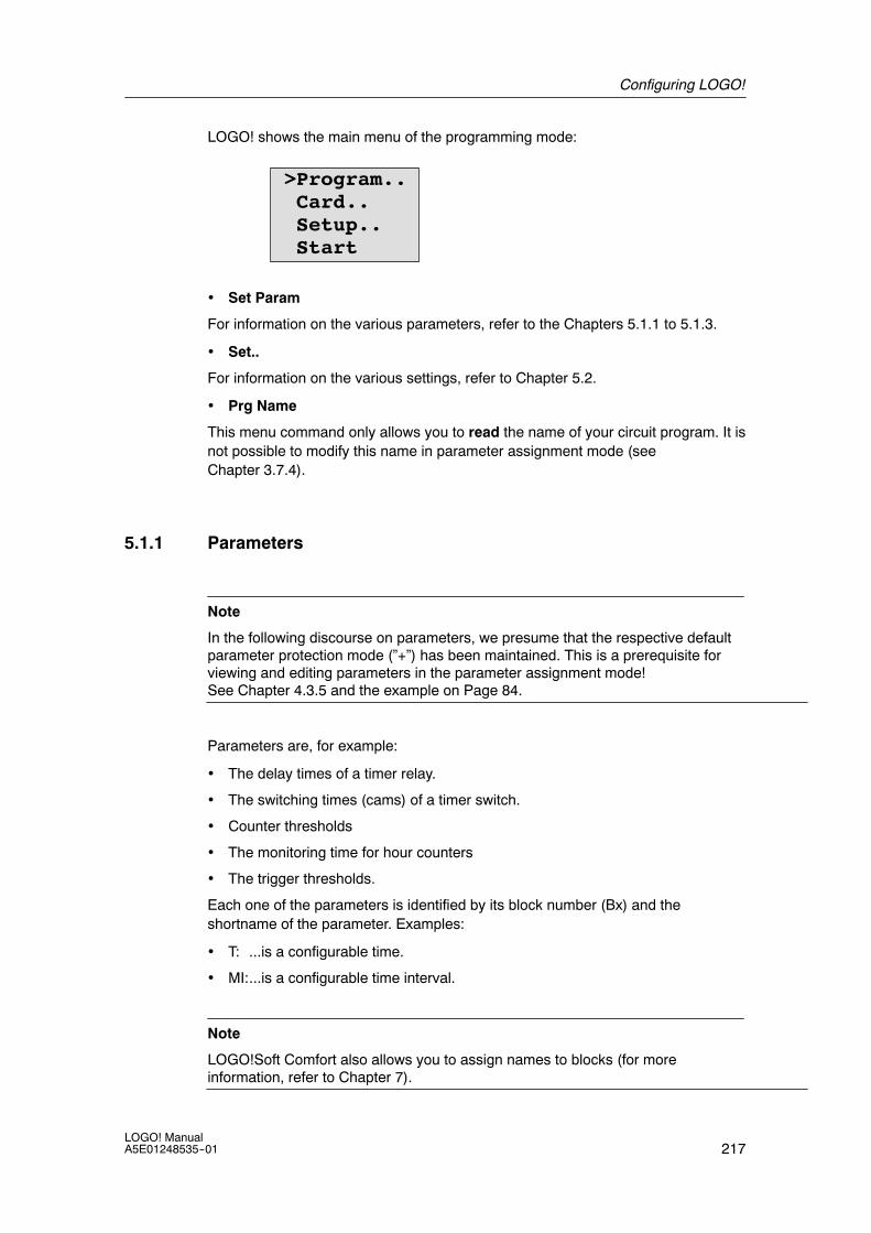
Configuring LOGO!
217LOGO! ManualA5E01248535--01
LOGO! shows the main menu of the programming mode:
>Program..Card..Setup..Start
• Set Param
For information on the various parameters, refer to the Chapters 5.1.1 to 5.1.3.
• Set..
For information on the various settings, refer to Chapter 5.2.
• Prg Name
This menu command only allows you to read the name of your circuit program. It isnot possible to modify this name in parameter assignment mode (seeChapter 3.7.4).
5.1.1 Parameters
Note
In the following discourse on parameters, we presume that the respective defaultparameter protection mode (”+”) has been maintained. This is a prerequisite forviewing and editing parameters in the parameter assignment mode!See Chapter 4.3.5 and the example on Page 84.
Parameters are, for example:
• The delay times of a timer relay.
• The switching times (cams) of a timer switch.
• Counter thresholds
• The monitoring time for hour counters
• The trigger thresholds.
Each one of the parameters is identified by its block number (Bx) and theshortname of the parameter. Examples:
• T: ...is a configurable time.
• MI:...is a configurable time interval.
Note
LOGO!Soft Comfort also allows you to assign names to blocks (for moreinformation, refer to Chapter 7).

Configuring LOGO!
218LOGO! Manual
A5E01248535--01
5.1.2 Selecting the parameters
To select a parameter:
1. On the parameter assignment menu, select’Set Param’: Press or
Stop>Set ParamSet..Prg Name
2. Confirm with OK.LOGO! shows the first parameter. If no parameter can be set, you can pressESC to return to the parameter assignment menu.
B9 1 Display number for functions with several displays
The value set at parameter T (Time)
The current time in LOGO!
Press ESCNo Param No parameters for editing:
Press ESC to return to the parameterassignment menu
T =60:00s
Ta =06:00s
Block number
3. Now, select the desired parameter: Press or .
4. Select the parameter you want to edit, and press OK.
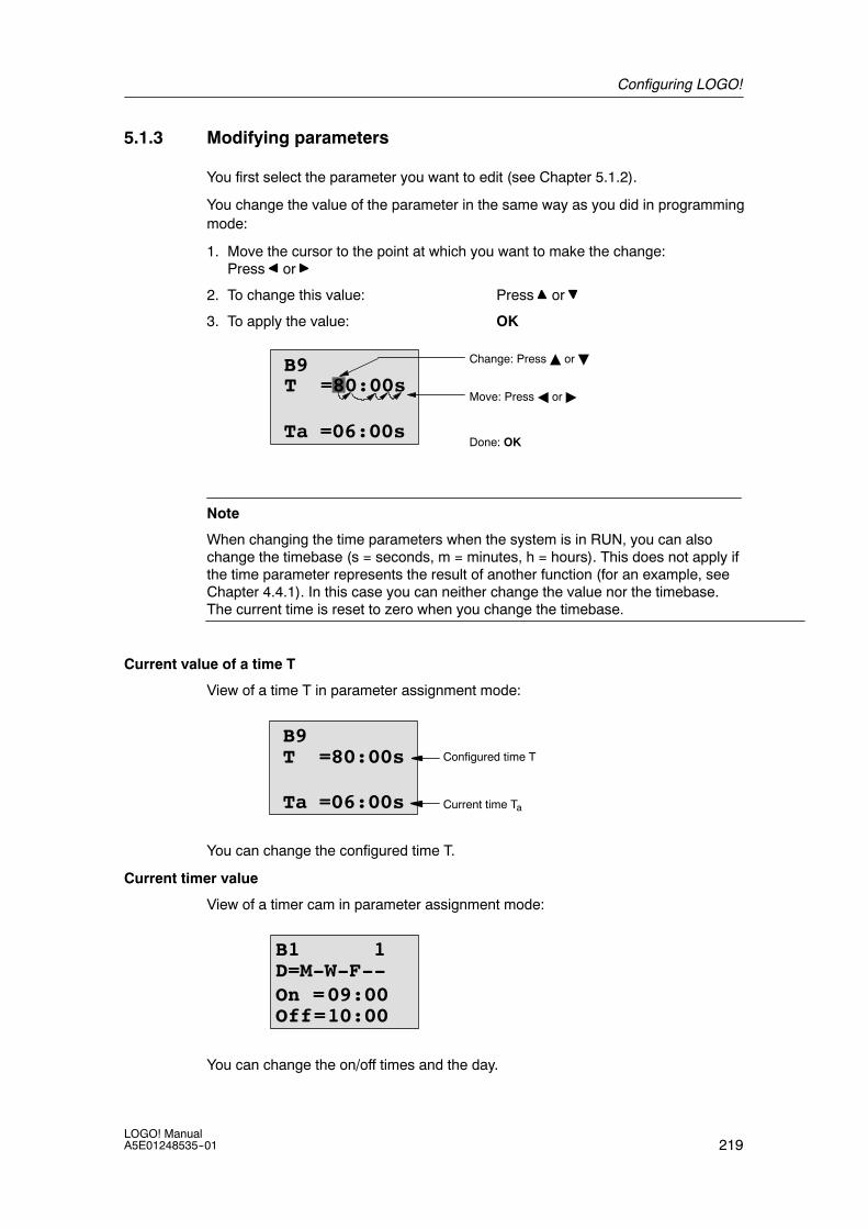
Configuring LOGO!
219LOGO! ManualA5E01248535--01
5.1.3 Modifying parameters
You first select the parameter you want to edit (see Chapter 5.1.2).
You change the value of the parameter in the same way as you did in programmingmode:
1. Move the cursor to the point at which you want to make the change:Press or
2. To change this value: Press or
3. To apply the value: OK
B9
Ta =06:00s
Move: PressA or"
Done: OK
T =80:00sChange: PressY orB
Note
When changing the time parameters when the system is in RUN, you can alsochange the timebase (s = seconds, m = minutes, h = hours). This does not apply ifthe time parameter represents the result of another function (for an example, seeChapter 4.4.1). In this case you can neither change the value nor the timebase.The current time is reset to zero when you change the timebase.
Current value of a time T
View of a time T in parameter assignment mode:
B9
Ta =06:00s
T =80:00s Configured time T
Current time Ta
You can change the configured time T.
Current timer value
View of a timer cam in parameter assignment mode:
B1 1
Off=10:00
D=M-W-F--On =09:00
You can change the on/off times and the day.

Configuring LOGO!
220LOGO! Manual
A5E01248535--01
Current value of a counter
View of a counter parameter in parameter assignment mode:
B3On =001234Off=000000Cnt=000120
orB3On =123456Off!B021Cnt=000120Current
count value
You can change the on/off threshold. This does not apply if the on or off thresholdrepresents the result of another function (in the example in section 4.4.13, this isB021 ).
Current value of an hour counter
View of an hour counter parameter in parameter assignment mode:
B16 1MI = 0100h
00 mTime interval
B16 2OT =00083h
15 mTotal operating hours
B16 3MN = 0016h
45 mTime-to-go
You can edit the configured time interval MI.
Current value of a threshold trigger
View of the parameter of a threshold trigger in parameter assignment mode:
B15On =0009Off =0005fa =0010
On threshold
Off threshold
Process variable
You can change the on/off threshold.

Configuring LOGO!
221LOGO! ManualA5E01248535--01
5.2 Setting the default values for LOGO!
You can set the following default values for a LOGO! Basic module:
Clock settings
You can set the default values for time-of-day and date, summertime/wintertimeconversion and synchronization:
• in parameter assignment mode by means of the set menu (“Clock” menu item)
• in programming mode by means of the setup menu (“Clock” menu item).
Time-of-day and date see Chapter 5.2.1.
Summertime/wintertime conversion see Chapter 3.7.14.
Synchronization see Chapter 3.7.15.
Contrast and backlight settings
You can set the default values for the display contrast and backlight:
• in parameter assignment mode by means of the set menu (“LCD” menu item)
• in programming mode by means of the setup menu (“LCD” menu item).
See Chapter 5.2.2.
Menu Language
You can set the language in which the LOGO! menus will be displayed:
• in parameter assignment mode by means of the set menu (“Menu Lang” menuitem)
• in programming mode by means of the setup menu (“Menu Lang” menu item)
Number of Basic Module Analog Inputs
The LOGO! Basic Modules LOGO! 24/o, and LOGO! 12/24RC/o support fouranalog inputs. Formerly they supported two. You can choose whether to use two orfour analog inputs on these modules:
• in parameter assignment mode by means of the set menu (“BM AI NUM” menuitem)
• in programming mode by means of the setup menu (“BM AI NUM” menu item)
Start screen settings
You can select the default setting for the start screen that displays on LOGO! andthe LOGO! TD when LOGO! transitions to RUN mode:
• in parameter assignment mode by means of the set menu (“StartScreen” menuitem)
See Chapter 5.2.5.
Message Text settings
You can select settings that apply to all message text function blocks from theProgramming menu. See Chapter 4.4.23.

Configuring LOGO!
222LOGO! Manual
A5E01248535--01
5.2.1 Setting the time of day and date (LOGO! ... C)
You can set the time of day and the date
• in parameter assignment mode by means of the set menu (“Clock” menu item)
• in programming mode by means of the setup menu (“Clock” menu item)
To set the TOD and the date in parameter assignment mode:
1. Select parameter assignment mode (see Chapter 5.1.)
2. On the parameter assignment menu, select ’Set..’: Press or
StopSet Param
>Set..Prg Name
3. Confirm ’Set..’: Press OK
4. Move the ’>’ cursor to ’Clock’: Press or
5. Confirm ’Clock’: Press OK
6. Move the ’>’ cursor to ’Set Clock’: Press or
7. Apply ’Set Clock’: Press OK
Note
The ’Set Clock’ command is only executed if your LOGO! is equipped with areal-time clock (LOGO!..C). You set the real-time clock of LOGO! by means of the’Set Clock’ command.
LOGO! shows the following display.
Set ClockMo 15:30YYYY-MM-DD2008-05-26
The cursor is positionedon the weekday.
8. Select the day of the week: Press or
9. Move the cursor to the next position: Press or
10.To change the value: Press or
11.To set the correct TOD, repeat steps 9. and 10.
12.To set the correct date, repeat steps 9. and 10.
13.To confirm your entries: Press OK

Configuring LOGO!
223LOGO! ManualA5E01248535--01
To set the TOD and the date in programming mode:
If you want to set the TOD and the date in programming mode, select ’Setup’ in themain menu, then menus ’Clock’ and ’Set Clock’. You can now set the weekdayand the time as described earlier (as of step 8.).
5.2.2 Setting the display contrast and backlight choice
You can set the default value for the display contrast
• in parameter assignment mode by means of the set menu (“LCD” menu item)
• in programming mode by means of the setup menu (“LCD” menu item).
To set the display contrast in parameter assignment mode:
1. Select parameter assignment mode (see Chapter 5.1.)
2. On the parameter assignment menu,select ’Set’: Press or
3. Confirm ’Set..’: Press OK
4. On the Set menu, select ’LCD’: Press or
5. Confirm ’LCD..’: Press OK
6. By default, the cursor points to Contrast.If not, move the ’>’ cursor to ’Contrast’: Press or
7. Confirm ’Contrast’: Press OK
LOGO! shows the following display:
Contrast
-.... ....+
8. To change the display contrast: Press or
9. To confirm your entry: Press OK
To set the display contrast in programming mode:
If you want to set the display contrast in programming mode, select ’Setup’ in themain menu, then menu ’Contrast’. You can now set the display contrast asdescribed earlier (as of step 8.).

Configuring LOGO!
224LOGO! Manual
A5E01248535--01
To set the back light choice in parameter assignment mode:
1. Select parameter assignment mode (see Chapter 5.1.)
2. On the parameter assignment menu,select ’Set’: Press or
3. Confirm ’Set..’: Press OK
4. On the Set menu, select ’LCD’: Press or
5. Confirm ’LCD..’: Press OK
6. Move the ’>’ cursor to ’Back light’: Press or
7. Confirm ’Back light’: Press OK
8. Move the ’>’ cursor to ’Default’or ’alwaysOn’: Press or
The default is that the back light is not on. To set the back light to always be on,select the ’alwaysOn’ choice.
To set the back light choice in programming mode:
If you want to set the backlight choice in programming mode, select ’Setup’ in themain menu, then menu ’LCD’. You can now set the back light choice as describedearlier (as of step 6.).
Note: The backlight lifetime of the LOGO! TD is 20,000 hours.
5.2.3 Setting the menu language
The language of the LOGO! menus can be one of nine predefined languages:
CN (Chinese) DE (German) EN (English) ES (Spanish) FR (French)
IT (Italian) NL (Dutch) RU (Russian) TR (Turkish)
To set the menu language in parameter assignment mode:
1. Select parameter assignment mode (see Chapter 5.1.)
2. On the parameter assignment menu,select ’Set’: Press or
3. Confirm ’Set..’: Press OK
4. On the Set menu, select ’Menu Lang’: Press or
5. Confirm ’Menu Lang’: Press OK
6. Move the ’>’ cursor to the languageof your choice: Press or
7. Confirm language selection. Press OK

Configuring LOGO!
225LOGO! ManualA5E01248535--01
To set the menu language in programming mode:
If you want to set the menu language in programming mode, select ’Setup’ in themain menu, then menu ’Menu Lang’. You can now set the menu language asdescribed earlier (as of step 6.).
5.2.4 Setting the number of AIs in the Basic Module
The first two input terminals of some LOGO! Basic modules can be used as eitherdigital inputs or as two additional analog inputs. If you choose to use them asanalog inputs, they are AI3 and AI4 respectively. Otherwise the module has onlyAI1 and AI2 on the rightmost input terminals. The LOGO! Basic Modules thatsupport the two additional optional AIs provide a menu setting for you to definewhether the module is to be used with two or four analog inputs. LOGO! BasicModules that do not support up to four analog inputs do not have this menuselection.
To set the number of AIs in parameter assignment mode:
1. Select parameter assignment mode (see Chapter 5.1.)
2. On the parameter assignment menu,select ’Set’: Press or
3. Confirm ’Set..’: Press OK
4. On the Set menu, select ’BM AI NUM’: Press or
5. Confirm ’BM AI NUM’: Press OK
6. Move to ’2AI’ or ’4AI’: Press or
7. Confirm selection. Press OK
To set the number of AIs in programming mode:
If you want to set the number of AIs in programming mode, select ’Setup’ in themain menu, then menu ’BM AI NUM’. You can now set the number of AIs asdescribed earlier (as of step 6.).
If you change the number of analog inputs, LOGO! restarts automatically.

Configuring LOGO!
226LOGO! Manual
A5E01248535--01
5.2.5 Setting the start screen
You can select the default setting for the start screen that LOGO! and the LOGO!TD will display in RUN mode. You make this selection from the parameterassignment mode by means of the set menu (“StartScreen” menu item).
To select the start screen:
1. Select parameter assignment mode (see Chapter 5.1.)
2. On the parameter assignment menu,select ’Set..’: Press or
3. Confirm ’Set..’: Press OK
4. Move to ’StartScreen’: Press or
5. Confirm ’StartScreen’: Press OK
LOGO! shows the following display:
>ClockInput DI
StartScreenClock
The current setting of the start screen is shown in the bottom row. The defaultsetting is ’Clock’.
You can choose between the display of the current time-of-day and date, or thevalues of the digital inputs:
6. Select the desired default setting: Press or .
7. To confirm your entry: Press OK
LOGO! displays your selection.
Power the LOGO! Basic module off then on to make your changes take effect.When LOGO! is in RUN mode, both LOGO! and the LOGO! TD will display thestart screen that you selected.

227LOGO! ManualA5E01248535--01
LOGO! memory and battery cards
LOGO! provides the following cards for program storage and real--time clockbackup:
• LOGO! Memory Card
• LOGO! Battery Card
• LOGO! Memory/Battery Card
Each of the three cards is color--coded to make them easily distinguishable fromone another. They also vary in size. The LOGO! Memory Card (purple)provides storage for the circuit program. The LOGO! Battery Card (green) providesbattery backup of the real--time clock for up to two years. The LOGO!Memory/Battery card (dark brown) provides both circuit program storage andbattery backup of the real--time clock.
!Warning
Risk of death, personal injury or property damage can occur if you use the batterycard or combined memory/battery card in a hazardous location.Use the battery card or combined memory/battery card only in non--hazardouslocations.
The LOGO! 0BA6 Memory Card and the LOGO! 0BA6 Memory/Battery Cardprovide 32 Kbytes memory space: four times the memory space of the LOGO!0BA5 Memory Card.
LOGO! allows you to store only one circuit program in its memory. If you want tomodify the circuit program or create an additional one without deleting the first, youmust archive it somewhere.
You can copy the LOGO! circuit program to a LOGO! Memory Card or LOGO!Memory/Battery card. You can then insert this card in another LOGO! in order tocopy the circuit program. This enables you to manage your programs in thefollowing ways:
• Archive circuit programs
• Reproduce circuit programs
• Send circuit programs by mail
• Write and test your circuit program at the office, and then transfer it to a LOGO!in the switching cabinet
LOGO! is supplied with a hood. The LOGO! Memory Card, LOGO! Battery Cardand LOGO! Memory/Battery Card are supplied separately.
6

LOGO! memory and battery cards
228LOGO! Manual
A5E01248535--01
Note
You do not need a memory card or combined memory/battery card to backup thecircuit program in your LOGO!.The LOGO! circuit program is automatically stored in nonvolatile memory whenyou exit the programming mode.
The memory card or combined memory/battery card can backup all data in theLOGO! circuit program memory. The order numbers are found in the appendix.

LOGO! memory and battery cards
229LOGO! ManualA5E01248535--01
Compatibility (Old memory cards in newer LOGO! modules)
... to earlier versions (0BA4 and 0BA5 devices):
Data written to the memory card in an 0BA5 version can be read in all 0BA6versions. 0BA4 memory cards cannot be read by 0BA6 versions.
... to earlier versions (0BA0 to 0BA3 devices):
A memory card that contains data written in earlier versions (0BA0...0BA3 devices)cannot be used in LOGO! devices of the 0BA4 and later generations. When theLOGO! system detects such an ’old’ memory card, the message “Unknown Card /Press ESC” is output to the display.
Vice versa, an 0BA4 or later memory card cannot be used in LOGO! devices of the0BA0...0BA3 family.
Compatibility (New memory, battery, or combined memory/battery cards in older LOGO!modules)
The LOGO! 0BA6 memory card can be used in 0BA4 or 0BA5 devices to store acircuit program but cannot be used in 0BA0..0BA3 devices.
A LOGO! 0BA6 Memory Card or LOGO! 0BA6 Memory/Battery Card that alreadyhas a LOGO! 0BA6 circuit program stored on it cannot be used in any device otherthan a LOGO! 0BA6 device.
A LOGO! 0BA6 Battery Card or LOGO! 0BA6 Memory/Battery Card can only beused in 0BA6 devices.
Upward compatibility of circuit programs
Circuit programs written for the previous versions 0BA0...0BA5 can be transferredto 0BA6 units from LOGO!Soft Comfort.
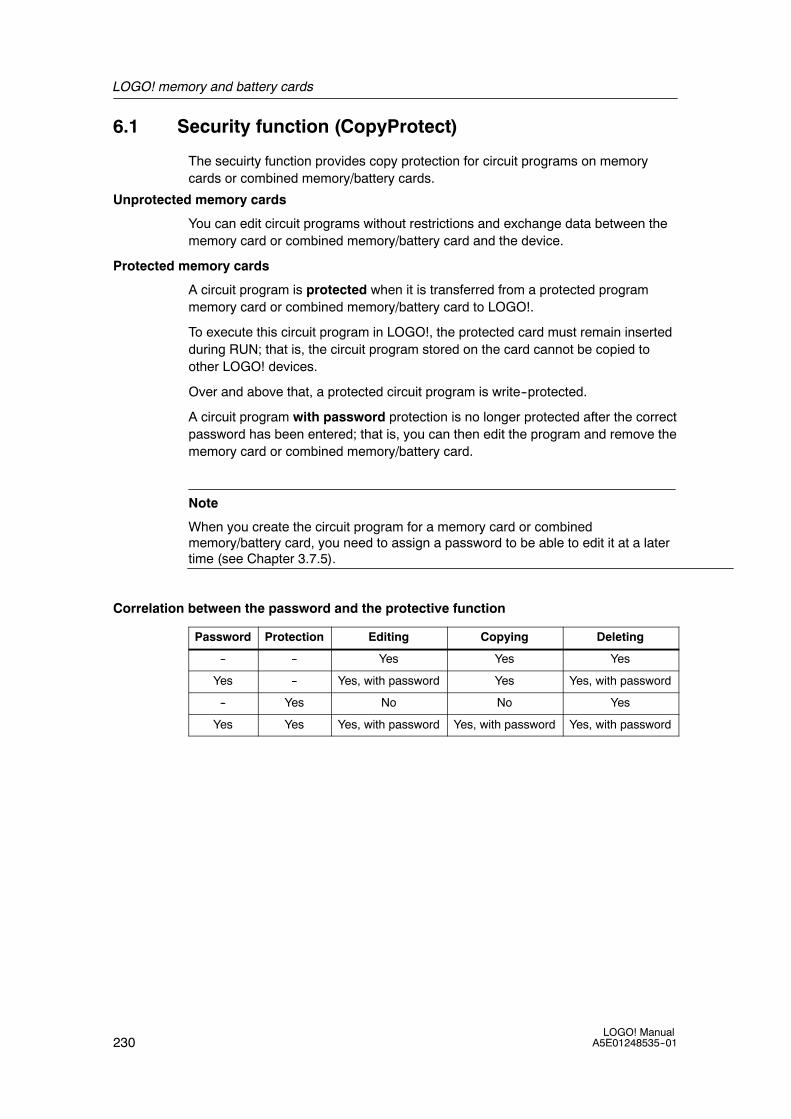
LOGO! memory and battery cards
230LOGO! Manual
A5E01248535--01
6.1 Security function (CopyProtect)
The secuirty function provides copy protection for circuit programs on memorycards or combined memory/battery cards.
Unprotected memory cards
You can edit circuit programs without restrictions and exchange data between thememory card or combined memory/battery card and the device.
Protected memory cards
A circuit program is protected when it is transferred from a protected programmemory card or combined memory/battery card to LOGO!.
To execute this circuit program in LOGO!, the protected card must remain insertedduring RUN; that is, the circuit program stored on the card cannot be copied toother LOGO! devices.
Over and above that, a protected circuit program is write--protected.
A circuit program with password protection is no longer protected after the correctpassword has been entered; that is, you can then edit the program and remove thememory card or combined memory/battery card.
Note
When you create the circuit program for a memory card or combinedmemory/battery card, you need to assign a password to be able to edit it at a latertime (see Chapter 3.7.5).
Correlation between the password and the protective function
Password Protection Editing Copying Deleting
-- -- Yes Yes Yes
Yes -- Yes, with password Yes Yes, with password
-- Yes No No Yes
Yes Yes Yes, with password Yes, with password Yes, with password
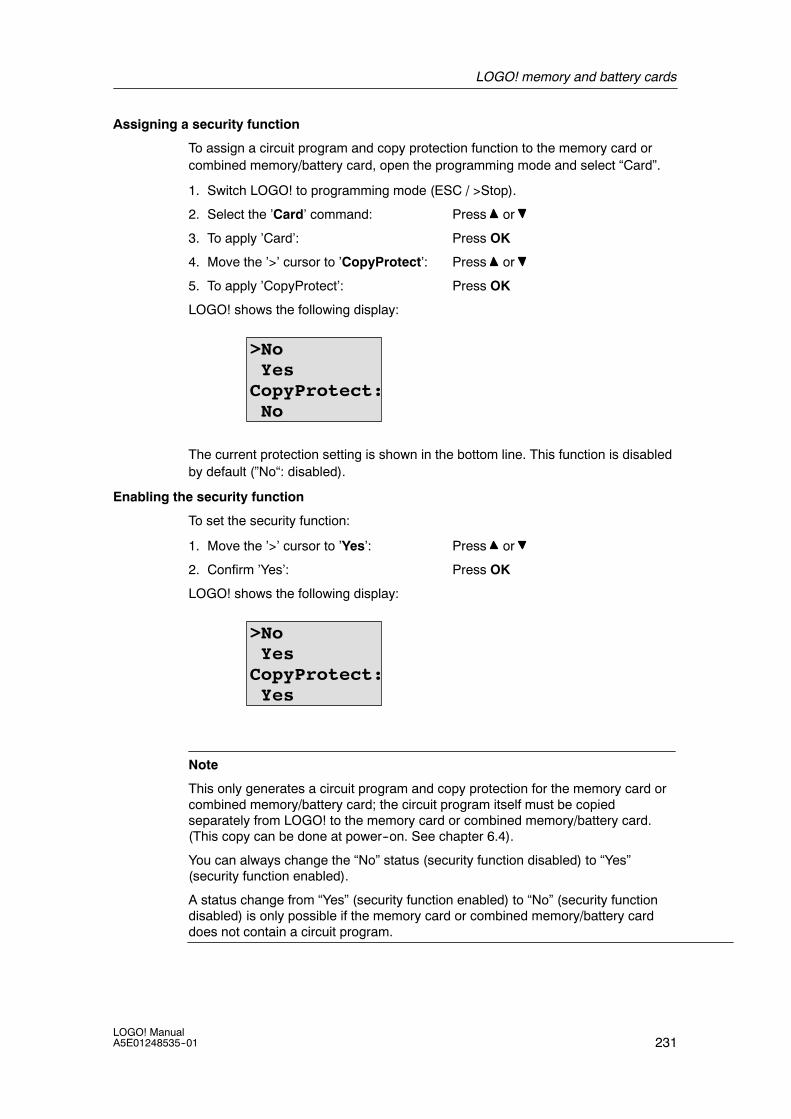
LOGO! memory and battery cards
231LOGO! ManualA5E01248535--01
Assigning a security function
To assign a circuit program and copy protection function to the memory card orcombined memory/battery card, open the programming mode and select “Card”.
1. Switch LOGO! to programming mode (ESC / >Stop).
2. Select the ’Card’ command: Press or
3. To apply ’Card’: Press OK
4. Move the ’>’ cursor to ’CopyProtect’: Press or
5. To apply ’CopyProtect’: Press OK
LOGO! shows the following display:
>NoYes
CopyProtect:No
The current protection setting is shown in the bottom line. This function is disabledby default (”No“: disabled).
Enabling the security function
To set the security function:
1. Move the ’>’ cursor to ’Yes’: Press or
2. Confirm ’Yes’: Press OK
LOGO! shows the following display:
>NoYes
CopyProtect:Yes
Note
This only generates a circuit program and copy protection for the memory card orcombined memory/battery card; the circuit program itself must be copiedseparately from LOGO! to the memory card or combined memory/battery card.(This copy can be done at power--on. See chapter 6.4).
You can always change the “No” status (security function disabled) to “Yes”(security function enabled).
A status change from “Yes” (security function enabled) to “No” (security functiondisabled) is only possible if the memory card or combined memory/battery carddoes not contain a circuit program.

LOGO! memory and battery cards
232LOGO! Manual
A5E01248535--01
6.2 Inserting and removing memory and battery cards
When you remove a memory card or combined memory/battery card that containsa circuit program with copy protection attributes, note the following: The circuitprogram stored on the card can only be executed if the card remains insertedduring system runtime.
After you have removed the memory card or combined memory/battery card,LOGO! outputs the message ’No Program’. A removal of the card during RUN willlead to impermissible operating states.
Always heed the following warning:
!Warning
Do not touch the open slot of the memory card with your fingers or with a metallicor conductive object.The memory card socket might be under voltage if the polarity is accidentallyreversed at L1 and N.The memory card, battery card or combined memory/battery card must only beremoved by qualified personnel.

LOGO! memory and battery cards
233LOGO! ManualA5E01248535--01
Removing the memory card, battery card or combined memory/battery card
To remove the memory card, carefully insert a screwdriver into the groove on theupper end of the card, and lever the module partially out of the slot. You can nowremove the memory card.
To remove a battery card, or combined memory/battery card, slide a screwdriverinto the slot on the upper surface of the card until it engages in the back, then withthe screwdriver engaged, pull the card out with your hand.
Inserting a memory card, battery card or combined memory/battery card
The entry of the memory card, battery card and the combined memory/battery cardslot is chamfered on its bottom right. The edge of the cards are chamferedaccordingly. This encoding prevents you from inserting cards the wrong way. Insertthe memory card, battery card or combined memory/battery card into the slot andpush it in until it engages.

LOGO! memory and battery cards
234LOGO! Manual
A5E01248535--01
6.3 Copying data from LOGO! to the memory card
To copy the circuit program to the memory card or combined memory/battery card:
1. Insert the memory card or combined memory/battery card into the slot.
2. Switch LOGO! to programming mode (ESC / >Stop).
>Program..Card..Setup..Start
LOGO! main menu
3. The main menu opens. To select the ’Card’ command: Press or
4. Press OK. The transfer menu opens.
> →CardCard→CopyProtect
= LOGO!
5. Move the ’>’ cursor to ’LOGO→ Card’ (if required): Press or
6. Press OK.
LOGO! now copies the circuit program to the memory card or combinedmemory/battery card. (If the memorycard is from an incompatible 0BA0..0BA4version, LOGO! displays this message: “Unknown Card / Press ESC” .)
When LOGO! has finished copying, it automatically returns you to the main menu:
>Program..Card..Setup..Start
The circuit program backup is now stored on your memory card or combinedmemory/battery card and you can remove the card. Do not forget to replace thecap.
If power fails while LOGO! is copying the circuit program, repeat the process afterPower On.
Note
The password of a protected circuit program in LOGO! also applies to the copiedprogram version on your memory card or combined memory/battery card.

LOGO! memory and battery cards
235LOGO! ManualA5E01248535--01
6.4 Copying data from the memory card to LOGO!
You can copy a circuit program from a compatible memory card or combinedmemory/battery card to LOGO! in one of two ways:
• Automatically during the startup of LOGO! (POWER ON)
• By means of the “Card” menu of LOGO!
Note
If the program on the module/card is protected with a password, the copiedprogram in LOGO! is also protected with the same password.
Automatic copying during the startup of LOGO!
Proceed as follows:
1. Switch off the power supply to LOGO! (POWER OFF)
2. Remove the slot cover.
3. Insert the program module/card into the relevant slot.
4. Switch on the power supply to LOGO!
LOGO! copies the program from the program module/card to LOGO!. (If thememorycard is from an incompatible 0BA0..0BA3 version, LOGO! displays thismessage: “Unknown Card / Press ESC” .)
When LOGO! has finished copying, it opens the main menu:
>Program..Card..Setup..Start
Note
Before you switch LOGO! to RUN, you must ensure that the system you arecontrolling with LOGO! does not represent a source of hazard.
1. Move the ’>’ cursor to ’Start’: Press or
2. Press OK.
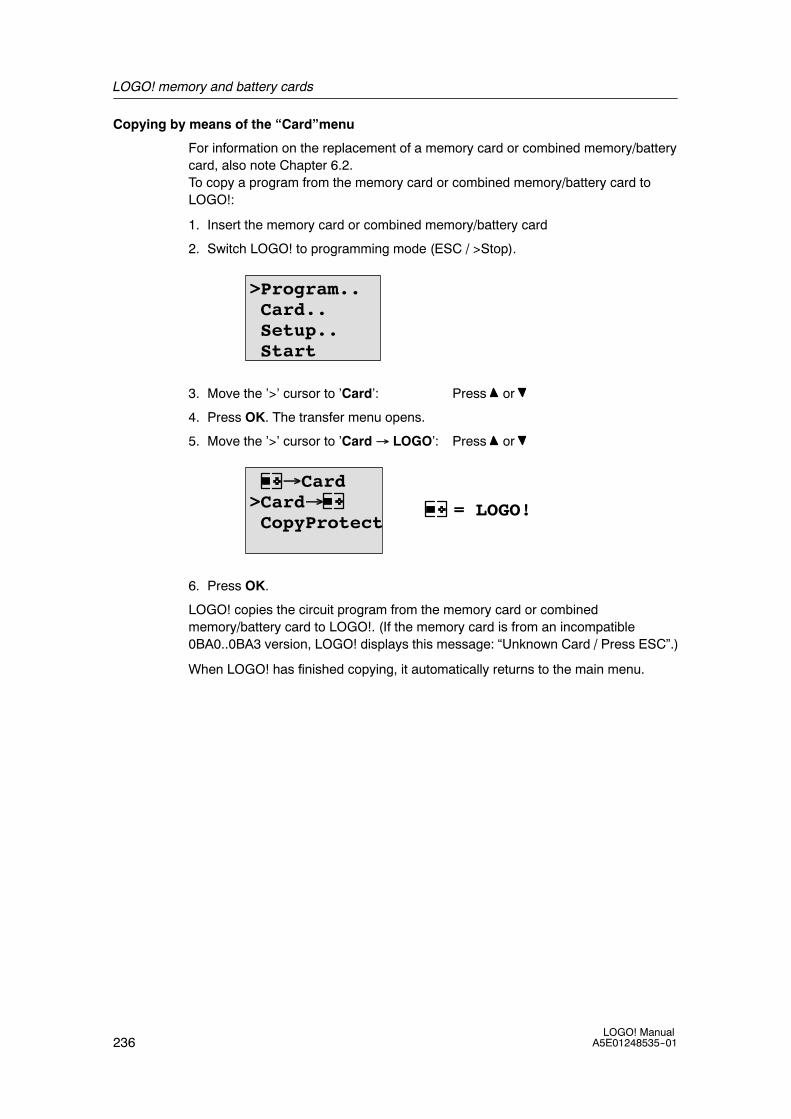
LOGO! memory and battery cards
236LOGO! Manual
A5E01248535--01
Copying by means of the “Card”menu
For information on the replacement of a memory card or combined memory/batterycard, also note Chapter 6.2.To copy a program from the memory card or combined memory/battery card toLOGO!:
1. Insert the memory card or combined memory/battery card
2. Switch LOGO! to programming mode (ESC / >Stop).
>Program..Card..Setup..Start
3. Move the ’>’ cursor to ’Card’: Press or
4. Press OK. The transfer menu opens.
5. Move the ’>’ cursor to ’Card→ LOGO’: Press or
= LOGO!
→Card>Card→CopyProtect
6. Press OK.
LOGO! copies the circuit program from the memory card or combinedmemory/battery card to LOGO!. (If the memory card is from an incompatible0BA0..0BA3 version, LOGO! displays this message: “Unknown Card / Press ESC”.)
When LOGO! has finished copying, it automatically returns to the main menu.

237LOGO! ManualA5E01248535--01
LOGO! software
LOGO!Soft Comfort is available as a programming package for the PC. Thissoftware provides many features, for example:
• A graphic interface for offline creation of your circuit program by means ofLadder Diagram (contact chart / circuit diagram) or Function Block Diagram(function chart)
• Simulation of your circuit program on the PC
• Generating and printing of an overview chart for the circuit program
• Saving a backup of the circuit program on the hard drive or other media
• Comparing circuit programs
• Easy configuration of blocks
• Transferring the circuit program in both directions:
-- from LOGO! to the PC
-- from the PC to LOGO!
• Reading the values of the hour counter
• Setting the time of day
• Summertime/wintertime conversion
• Online test: Display of status changes and process variables of LOGO! in RUNmode:
-- Status of a digital I/O, flags, shift register bits and cursor keys
-- The values of all analog I/Os and flags
-- The results of all blocks
-- The current values (including the times) of selected blocks
• Starting and stopping circuit program execution via the PC (RUN, STOP)
The LOGO! alternatives
As you can see, LOGO!Soft Comfort represents an alternative to conventionalengineering methods, with several advantages:
• You can develop the circuit program on your PC.
• You simulate the circuit program on your computer and verify its functionsbefore you actually implement it in your system.
• You can add comments to the circuit program and create hardcopies.
• You can save a copy of your circuit program to the file system on your PC, tomake it directly available for modifications.
• It takes only a few key actions to download the circuit program to LOGO!.
7

LOGO! software
238LOGO! Manual
A5E01248535--01
LOGO!Soft Comfort
LOGO!Soft Comfort runs under Windows VistaR, Windows 98R, Windows NT 4.0R,Windows MeR, Windows 2000R, Windows XPR, LinuxRand Mac OS XR.LOGO!Soft Comfort is capable of client/server operation and offers you a highdegree of freedom and comfort for creating your circuit program.
LOGO!Soft Comfort V6.0
This is the current version of LOGO!Soft Comfort. You will find all the functions andthe functionality of the devices described in this manual in the version 6.0.
Upgrading previous LOGO!Soft Comfort versions
You can use the Upgrade to LOGO!Soft Comfort V6.0 software to upgradeLOGO!Soft Comfort V1.0, V2.0, V3.0, V4.0 or V5.0 to V6.0.
Order numbers are in Appendix E.
Note
If a full version is not installed, you can carry out an upgrade as follows:
• Install the software from the CD.
• When the system prompts you for the previous version, place the oldLOGO!Soft Comfort CD in the CD drive.
• Point your browser to the “...\Tools\Application” directory on the CD.
Updates and info
You can download demo versions of the software free of charge from the Internetaddress specified in the preface.
For detailed information on updates, upgrades and the LOGO!Soft Comfort UpdateCenter, refer to the LOGO!Soft Comfort online help.

LOGO! software
239LOGO! ManualA5E01248535--01
7.1 Connecting LOGO! to a PC
Connecting the PC cable
To connect LOGO! to a PC, you need the LOGO! PC cable (Appendix E lists theorder number).
Turn the power off to the LOGO! Basic module. Remove the cap, memory card, orcombined memory/battery card from your LOGO! and connect the cable to thissocket. Connect the other end of the cable to the serial port of your PC.
Connecting the USB PC cable
You can also connect LOGO! to the PC with the LOGO! USB PC cable (AppendixE lists the order number).
Remove the cap or memory card, battery card, or combined memory/battery cardfrom your LOGO! and connect the cable to this socket.Connect the other end of thecable to a USB port of your PC.
Switching LOGO! to PC↔LOGO mode
Switch the LOGO! with/without display to STOP from your PC (refer to theLOGO!Soft Comfort online help), or select the ESC / >Stop command on a devicewith display and confirm the entry with ’Yes’.
When LOGO! is in STOP and online with the PC, the following PC commands areaccepted:
• Switch LOGO! to RUN
• Read/write the circuit program
• Read/write the summertime/wintertime
When you start the upload/download in STOP, the following display appearsautomatically:
PC↔ = LOGO!

LOGO! software
240LOGO! Manual
A5E01248535--01
Note
You can switch earlier versions up to 0BA3 with/without display to PC↔LOGOmode as follows:
1. Switch off the power supply to LOGO!.
2. Remove the cover or the memory, battery, or combined memory/battery cardand connect the cable to this socket.
3. Switch on power.
LOGO! switches automatically to PC↔ LOGO mode.
The PC can now access LOGO! For information on this function, refer to theLOGO!Soft Comfort Online Help.
For more information on LOGO! versions without display, refer to Appendix C.
Closing the PC↔LOGO mode
When the data transfer is completed, the connection to the PC is shut downautomatically.
Note
If the circuit program created with LOGO!Soft Comfort is password protected, boththe circuit program and the password are downloaded to LOGO!. The passwordprompt is enabled at the end of the data transfer.
The upload of a password protected program created in LOGO! is only possibleafter the correct password is entered in LOGO!Soft Comfort.

241LOGO! ManualA5E01248535--01
Applications
Note
LOGO! sample applications are available to all our customers free of charge on theInternet at
http://www.siemens.com/logo
(go to Products & Solutions --> Applications --> Application Examples).
The examples provided are not guaranteed to be error--free; they serve as generalinformation about the fields of application for LOGO!, and may be different fromuser-specific solutions. Siemens reserves the right to make changes.
The user operates the system at his own responsibility. For safety concerns, referto the relevant national standards and system-related installation regulations.
On the Internet you can find the following sample applications, tips for furtherapplications, and more:
• Irrigation system for greenhouse plants
• Conveyor control system
• Bending machine control system
• Shop window lighting
• Bell system (e.g. in a school)
• Parking lot surveillance
• Outdoor lighting
• Shutter control system
• Domestic outdoor and indoor lighting system
• Control system of a cream stirrer
• Sports hall lighting
• Constant load on 3 consumers
• Sequential control system for cable-welding machines for large cross-sections
• Step switch (e.g. for fans)
• Sequential control for boilers
• Control system for several pump sets with centralized operator control
• Cutting device (e.g. for detonating fuses)
• Monitoring periods of utilization, for example of a solar energy system
8

Applications
242LOGO! Manual
A5E01248535--01
• Intelligent foot switches, for example for speed preselection)
• Elevating platform controls
• Impregnation of textiles, heating and conveyor belt controls
• Silo-filling system
• Fill station with message text on the LOGO! TD that displays the sum ofcounted objects
On the Web you can also find descriptions and the corresponding circuit diagramsof the applications. You can read these *.pdf files with the Adobe AcrobatReader. Ifyou have installed LOGO!Soft Comfort on your computer, you can simply click thedisk icon to download the relevant circuit programs, which you can then adapt tosuit your application and download to LOGO! directly via the PC cable.
Benefits of LOGO!
LOGO! is a particularly useful feature
• For replacing auxiliary switchgear with the integrated LOGO! functions
• For saving wiring and installation work - because LOGO! keeps the wiring ”in itshead”.
• For reducing space requirements for components in the controlcabinet/distribution box. A smaller control cabinet/distribution box may providesufficient space.
• For adding or changing functions, without having to install additional switchgearor change the wiring.
• For offering your customers new, additional functions for domestic andcommercial housing installations. Examples:
-- Domestic security systems: LOGO! switches on a lamp at regular intervals oropens and closes the shutters while you are on holiday.
-- Central heating: LOGO! runs the circulation pump only when water orheating is actually required.
-- Refrigerating systems: LOGO! can defrost refrigerating systems at regularintervals to save energy costs.
-- You can illuminate aquaria and terraria on a time-dpendent basis.
Last but not least you can:
• Use commonly available switches and pushbuttons, which makes it easy toinstall a domestic system.
• Connect LOGO! directly to your domestic installation; the integrated powersupply makes it possible.

Applications
243LOGO! ManualA5E01248535--01
Do you want more Info?
For more information about LOGO!, see our web page (see the preface for theURL).
Do you have any suggestions?
There are definitely many more useful applications for LOGO! . If you know of one,why not write to us? We will collect all the suggestions made and distribute asmany of them as we can. No matter whether your LOGO! circuit is particularlycomplex or simple, simply write to us. We shall be delighted to receive all yoursuggestions.
Write to:
Siemens AGA&D AS FA PS4PO box 48 48
D-90327 Nuremberg

Applications
244LOGO! Manual
A5E01248535--01

245LOGO! ManualA5E01248535--01
Technical data
A.1 General technical data
Criterion Tested in accordance with Values
LOGO!Basic
Dimensions (WxHxD) 72 x 90 x 55 mmWeight Approx. 190 g
Installation on a 35 mm profile rail4 module widthsor wall mounting
LOGO! expansion modulesDM8..., AM...Dimensions (WxHxD) 36 x 90 x 53 mm
Weight Approx. 90 g
Installation on a 35 mm profile rail2 module widthsor wall mounting
LOGO! TD (Text Display) 128.2 x 86 x 38.7 mm
Approx. 220g
Bracket mounting
LOGO! expansion modules DM16...
Dimensions (WxHxD) 72 x 90 x 53 mm
Weight Approx. 190 gInstallation on a 35 mm profile rail
4 module widthsor wall mounting
Climatic conditions
Ambient temperature
Horizontal installation
Low temperature to IEC60068-2-1 0 ... 55 ˚CHorizontal installation
Vertical installation
60068 2 1High temperature to IEC60068-2-2
0 ... 55 C
0 ... 55 ˚C
Storage/shipping -40 ˚C ... +70 ˚CRelative humidity IEC 60068-2-30 From 10 to 95 %
no condensationAir pressure 795 ... 1080 hPa
Pollutants IEC 60068-2-42
IEC 60068-2-43
SO2 10 cm3 /m3, 10 days
H2S 1 cm3 /m3, 10 daysAmbient mechanical conditions
Degree of protection IP 20 for LOGO! Basic modulefront panelIP 65 for LOGO! TD front panel
A

Technical data
246LOGO! Manual
A5E01248535--01
Criterion ValuesTested in accordance withVibrations: IEC 60068-2-6 5 ... 8.4 Hz
(constant amplitude 3.5 mm)
8.4 ... 150 Hz(constant acceleration 1 g)
Shock IEC 60068-2-27 18 shocks(half-sine wave 15g/11 ms)
Free fall (packaged) IEC 60068-2-32 0.3 m
Electromagnetic compatibility (EMC)
Noise emission EN 55011/AEN 55022/B
EN 50081-1(domestic area)
Limit class B group 1
Electrostatic discharge IEC 61000-4-2
Severity 3
8 kV air discharge
6 kV contact dischargeElectromagnetic fields IEC 61000-4-3 Field strength 1 V/m and 10 V/mHF currents on cables and cableshielding
IEC 61000-4-6 10 V
Burst pulses IEC 61000-4-4Severity 3
2 kV (supply and signal lines)
High-energy surge pulse(applies only toLOGO! 230 ...)
IEC 61000-4-5Severity 3
1 kV (power lines)symmetrical
2 kV (power lines)asymmetrical
Safety to IEC
Clearance and creepage distancerating
IEC 60664,IEC 61131-2, EN 50178cULus to UL 508, CSAC22.2 No. 142With LOGO!230 R/RC,also IEC60730--1
Fulfilled
Insulation strength IEC 61131-2 Fulfilled
Cycle time
Cycle time per function < 0.1 ms
Startup
Startup time at power-up typ. 9 s

Technical data
247LOGO! ManualA5E01248535--01
A.2 Technical data: LOGO! 230...
LOGO! 230 RCLOGO! 230 RCo
Power supply
Input voltage 115...240 V AC/DC
Permissible range 85 ... 265 V AC100 ... 253 V DC
Permissible mains frequency 47 ... 63 Hz
Power consumption
• 115 V AC 15 ... 40 mA
• 240 V AC 15 ... 25 mA
• 115 V DC 10 ... 25 mA
• 240 V DC 6 ... 15 mA
Voltage failure buffering
• 115 V AC/DC typ 10 ms• 115 V AC/DC typ. 10 ms
• 240 V AC/DC
yp
typ 20 ms• 240 V AC/DC typ. 20 ms
Power loss at
• 115 V AC 1.7 ... 4.6 W
• 240 V AC 3.6 ... 6.0 W
• 115 V DC 1.1... 2.9 W
• 240 V DC 1.4 ... 3.6 W
Backup of the real-time clock at 25 _C typ. 80 hours without battery cardtyp. 2 years with battery card
Accuracy of the real-time clock typ.2 s / day
Digital inputs
Number 8
Electrical isolation No
Input voltage L1
• Signal 0
• Signal 1
< 40 V AC
> 79 V AC• Signal 1
• Signal 0
• Signal 1
> 79 V AC
< 30 V DC
> 79 V DC
Input current at
• Signal 0
• Signal 1
• Signal 0
• Signal 1
< 0.03 mA AC> 0.08 mA AC
< 0.03 mA DC
> 0.12 mA DC
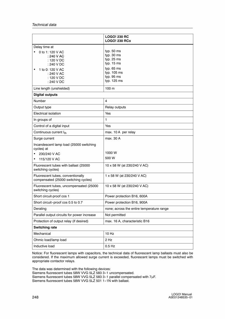
Technical data
248LOGO! Manual
A5E01248535--01
LOGO! 230 RCLOGO! 230 RCo
Delay time at
• 0 to 1: 120 V AC: 240 V AC
typ. 50 mstyp. 30 ms: 240 V AC
: 120 V DC: 240 V DC
• 1 to 0: 120 V AC
yptyp. 25 mstyp. 15 ms
typ. 65 mst 105
1 to 0: 120 V AC: 240 V AC: 120 V DC: 240 V DC
typ. 105 mstyp. 95 mstyp. 125 ms
Line length (unshielded) 100 m
Digital outputs
Number 4
Output type Relay outputs
Electrical isolation Yes
In groups of 1
Control of a digital input Yes
Continuous current Ith max. 10 A per relay
Surge current max. 30 A
Incandescent lamp load (25000 switchingcycles) at
• 230/240 V AC
• 115/120 V AC
1000 W
500 W
Fluorescent tubes with ballast (25000switching cycles)
10 x 58 W (at 230/240 V AC)
Fluorescent tubes, conventionallycompensated (25000 switching cycles)
1 x 58 W (at 230/240 V AC)
Fluorescent tubes, uncompensated (25000switching cycles)
10 x 58 W (at 230/240 V AC)
Short circuit-proof cos 1 Power protection B16, 600A
Short circuit--proof cos 0.5 to 0.7 Power protection B16, 900A
Derating none; across the entire temperature range
Parallel output circuits for power increase Not permitted
Protection of output relay (if desired) max. 16 A, characteristic B16
Switching rate
Mechanical 10 Hz
Ohmic load/lamp load 2 Hz
Inductive load 0.5 Hz
Notice: For fluorescent lamps with capacitors, the technical data of fluorescent lamp ballasts must also beconsidered. If the maximum allowed surge current is exceeded, fluorescent lamps must be switched withappropriate contactor relays.
The data was determined with the following devices:Siemens fluorescent tubes 58W VVG 5LZ 583 3--1 uncompensated.Siemens fluorescent tubes 58W VVG 5LZ 583 3--1 parallel compensated with 7μF.Siemens fluorescent tubes 58W VVG 5LZ 501 1--1N with ballast.
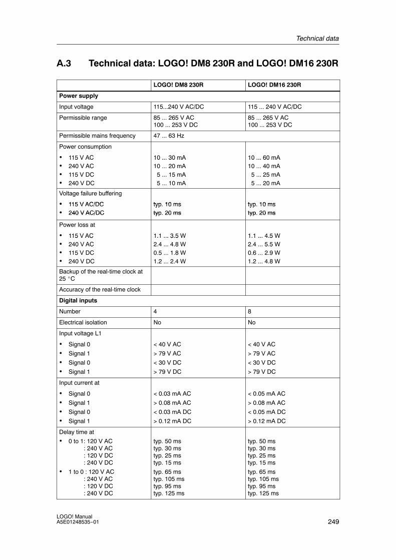
Technical data
249LOGO! ManualA5E01248535--01
A.3 Technical data: LOGO! DM8 230R and LOGO! DM16 230R
LOGO! DM8 230R LOGO! DM16 230R
Power supply
Input voltage 115...240 V AC/DC 115 ... 240 V AC/DC
Permissible range 85 ... 265 V AC100 ... 253 V DC
85 ... 265 V AC100 ... 253 V DC
Permissible mains frequency 47 ... 63 Hz
Power consumption
• 115 V AC 10 ... 30 mA 10 ... 60 mA115 V AC• 240 V AC
10 ... 30 mA10 ... 20 mA
10 ... 60 mA10 ... 40 mA0 C
• 115 V DC0 05 ... 15 mA
0 05 ... 25 mA
• 240 V DC 5 ... 10 mA 5 ... 20 mA
Voltage failure buffering
• 115 V AC/DC typ 10 ms typ 10 ms• 115 V AC/DC typ. 10 ms typ. 10 ms• 240 V AC/DC
yptyp. 20 ms
yptyp. 20 ms• 240 V AC/DC typ. 20 ms typ. 20 ms
Power loss at
• 115 V AC 1.1 ... 3.5 W 1.1 ... 4.5 W115 V AC• 240 V AC
1.1 ... 3.5 W2.4 ... 4.8 W
1.1 ... 4.5 W2.4 ... 5.5 W0 C
• 115 V DC8
0.5 ... 1.8 W5 5
0.6 ... 2.9 W• 240 V DC 1.2 ... 2.4 W 1.2 ... 4.8 W
Backup of the real-time clock at25 _C
Accuracy of the real-time clock
Digital inputs
Number 4 8
Electrical isolation No No
Input voltage L1
• Signal 0
• Signal 1
• Signal 0
• Signal 1
< 40 V AC
> 79 V AC
< 30 V DC
> 79 V DC
< 40 V AC
> 79 V AC
< 30 V DC
> 79 V DC
Input current at
• Signal 0
• Signal 1
< 0.03 mA AC
> 0.08 mA AC
< 0.05 mA AC
> 0.08 mA ACg
• Signal 0
• Signal 1
< 0.03 mA DC
> 0.12 mA DC
< 0.05 mA DC
> 0.12 mA DC
Delay time at
• 0 to 1: 120 V AC: 240 V AC: 120 V DC: 240 V DC
• 1 to 0 : 120 V AC: 240 V AC: 120 V DC: 240 V DC
typ. 50 mstyp. 30 mstyp. 25 mstyp. 15 ms
typ. 65 mstyp. 105 mstyp. 95 mstyp. 125 ms
typ. 50 mstyp. 30 mstyp. 25 mstyp. 15 ms
typ. 65 mstyp. 105 mstyp. 95 mstyp. 125 ms

Technical data
250LOGO! Manual
A5E01248535--01
LOGO! DM16 230RLOGO! DM8 230R
Line length (unshielded) 100 m 100 m
Digital outputs
Number 4 8
Output type Relay outputs Relay outputs
Electrical isolation Yes Yes
In groups of 1 1
Control of a digital input Yes Yes
Continuous current Ith max. 5 A per relay max. 5 A per relay
Surge current max. 30 A max. 30 A
Incandescent lamp load (25000switching cycles) at
230/240 V AC
115/120 V AC
1000 W
500 W
1000 W
500 W
Fluorescent tubes with ballast(25000 switching cycles)
10 x 58 W(at 230/240 V AC)
10 x 58 W (at 230/240 V AC)
Fluorescent tubes,conventionally compensated(25000 switching cycles)
1 x 58 W(at 230/240 V AC)
1 x 58 W (at 230/240 V AC)
Fluorescent tubes,uncompensated (25000switching cycles)
10 x 58 W (at 230/240 V AC) 10 x 58 W (at 230/240 V AC)
Short circuit-proof cos 1 Power protection B16, 600A Power protection B16, 600A
Short circuit--proof cos 0.5 to 0.7 Power protection B16, 900A Power protection B16, 900A
Derating none; across the entiretemperature range
none; across the entiretemperature range
Parallel output circuits for powerincrease
Not permitted Not permitted
Protection of output relay(if desired)
max. 16 A,characteristic B16
max. 16 A,characteristic B16
Switching rate
Mechanical 10 Hz 10 Hz
Ohmic load/lamp load 2 Hz 2 Hz
Inductive load 0.5 Hz 0.5 Hz
Notice: For fluorescent lamps with capacitors, the technical data of fluorescent lamp ballasts must also beconsidered. If the maximum allowed surge current is exceeded, fluorescent lamps must be switched withappropriate contactor relays.
The data was determined with the following devices:Siemens fluorescent tubes 58W VVG 5LZ 583 3--1 uncompensated.Siemens fluorescent tubes 58W VVG 5LZ 583 3--1 parallel compensated with 7μF.Siemens fluorescent tubes 58W VVG 5LZ 501 1--1N with ballast.

Technical data
251LOGO! ManualA5E01248535--01
A.4 Technical data: LOGO! 24...
LOGO! 24LOGO! 24o
Power supply
Input voltage 24 V DC
Permissible range 20.4 ... 28.8 V DC
Reverse polarity protection Yes
Permissible mains frequency not applicable for this module
Power consumption from 24 V DC 40 ... 75 mA
0.3 A per output
Voltage failure buffering
Power loss at 24 V 1.0 ... 1.8 W
Backup of the real-time clock at 25 _C no clock available
Accuracy of the real-time clock no clock available
Digital inputs
Number 8
Electrical isolation No
Input voltage L+
• Signal 0 < 5 V DCg
• Signal 1 > 12 V DC
Input current at
• Signal 0 < 0.85 mA (I3...I6)< 0.05 mA (I1, I2, I7, I8)
• Signal 1
( , , , )
> 2 mA (I3... I6)> 0.15 mA (I1, I2, I7, I8)
Delay time at
• 0 to 1 typ. 1.5 ms<1.0 ms (I3 ... I6)
• 1 to 0 typ. 1.5 ms<1.0 ms (I3 ... I6)
Line length (unshielded) 100 m
Analog inputs
Number 4 (I1=AI3, I2=AI4, I7=AI1, I8=AI2)
Range 0 ... 10 V DCinput impedance 72 kΩ
Cycle time for analog value generation 300 ms
max. input voltage 28.8 V
Line length (shielded and twisted) 10 m
Error limit +/-- 1.5% at FS
Digital outputs
Number 4

Technical data
252LOGO! Manual
A5E01248535--01
LOGO! 24LOGO! 24o
Output type Transistor,current-sourcing (1)
Electrical isolation No
In groups of
Control of a digital input Yes
Output voltage ≙ Supply voltage
Output current max. 0.3 A
Short circuit-proof and overload-proof Yes
Short circuit current limitation Approx. 1 A
Derating none; across the entire temperature range
Short circuit-proof cos 1 not applicable for this module
Short circuit--proof cos 0.5 to 0.7 not applicable for this module
Parallel output circuit for power increase Not permitted
Protection of output relay (if desired)
Switching rate (2)
Mechanical not applicable for this module
Electrical 10 Hz
Ohmic load/lamp load 10 Hz
Inductive load 0.5 Hz
(1): When LOGO! 24, LOGO! 24o, LOGO! DM8 24 or LOGO! DM16 24 are switched on, signal 1 is sent to the digitaloutputs for about 50 microseconds. Take this into account, especially when using devices that react to short pulses.(2): The maximum switching rate is only dependent on the switching program’s cycle time.

Technical data
253LOGO! ManualA5E01248535--01
A.5 Technical data: LOGO! DM8 24 and LOGO! DM16 24
LOGO! DM8 24 LOGO! DM16 24
Power supply
Input voltage 24 V DC 24 V DC
Permissible range 20.4 ... 28.8 V DC 20.4 ... 28.8 V DC
Reverse polarity protection Yes Yes
Permissible mains frequency not applicable for this module not applicable for this module
Power consumption from 24 VDC
30 ... 45 mA
0.3 A per output
30 ... 45 mA
0.3 A per output
Voltage failure buffering
Power loss at 24 V 0.8 ... 1.1 W 0.8 ... 1.7 W
Backup of the real-time clock at25 _C
no clock available no clock available
Accuracy of the real-time clock no clock available no clock available
Digital inputs
Number 4 8
Electrical isolation No No
Input voltage L+ L+
• Signal 0 < 5 V DC < 5 V DCg
• Signal 1 > 12 V DC > 12 V DC
Input current at
• Signal 0 < 0.85 mA < 0.85 mAg
• Signal 1 > 2 mA > 2 mA
Delay time at
• 0 to 1 typ. 1.5 ms typ. 1.5 ms
• 1 to 0
yp
typ. 1.5 ms
yp
typ. 1.5 ms
Line length (unshielded) 100 m 100 m
Digital outputs
Number 4 8
Output type Transistor,current-sourcing (1)
Transistor,current-sourcing (1)
Electrical isolation No No
In groups of
Control of a digital input Yes Yes
Output voltage ≙ Supply voltage ≙ Supply voltage
Output current max. 0.3 A max. 0.3 A
Short circuit-proof andoverload-proof
Yes Yes
Short circuit current limitation Approx. 1 A Approx. 1 A
Derating none; across the entiretemperature range
none; across the entiretemperature range

Technical data
254LOGO! Manual
A5E01248535--01
LOGO! DM16 24LOGO! DM8 24
Short circuit-proof cos 1 not applicable for this module not applicable for this module
Short circuit--proof cos 0.5 to 0.7 not applicable for this module not applicable for this module
Parallel output circuit for powerincrease
Not permitted Not permitted
Protection of output relay (ifdesired)
Switching rate
Mechanical
Electrical 10 Hz 10 Hz
Ohmic load/lamp load 10 Hz 10 Hz
Inductive load 0.5 Hz 0.5 Hz
(1): When LOGO! 24, LOGO! 24o, LOGO! DM8 24 or LOGO! DM16 24 are switched on, signal 1 is sentto the digital outputs for about 50microseconds. Take this into account, especially when using devices thatreact to short pulses.

Technical data
255LOGO! ManualA5E01248535--01
A.6 Technical data: LOGO! 24RC...
LOGO! 24RCLOGO! 24RCo
Power supply
Input voltage 24 V AC/DC
Permissible range 20.4 ... 26.4 V AC20.4 ... 28.8 V DC
Reverse polarity protection not applicable for this module
Permissible mains frequency 47 ... 63 Hz
Power consumption
• 24 V AC
• 24 V DC
45 ... 130 mA
40 ... 100 mA
Voltage failure buffering typ. 5 ms
Power loss
• 24 V AC
• 24 V DC
1.1... 3.1 W
1.0 ... 2.4 W
Backup of the real-time clock at 25 _C typ. 80 hours without battery cardtyp. 2 years with battery card
Accuracy of the real-time clock typ.2 s / day
Digital inputs
Number 8,optional P action or N action
Electrical isolation No
Input voltage L
• Signal 0 < 5 V AC/DCg
• Signal 1 > 12 V AC/DC
Input current at
• Signal 0 < 1.0 mAg
• Signal 1 > 2.5 mA
Delay time at
• 0 to 1 typ. 1.5 ms
• 1 to 0
yp
typ. 15 ms
Line length (unshielded) 100 m
Analog inputs
Number
Range
max. Input voltage
Digital outputs
Number 4
Output type Relay outputs
Electrical isolation Yes
In groups of 1

Technical data
256LOGO! Manual
A5E01248535--01
LOGO! 24RCLOGO! 24RCo
Control of a digital input Yes
Continuous current Ith max. 10 A per relay
Surge current max. 30 A
Incandescent lamp load (25000 switchingcycles) at
1000 W
Fluorescent tubes with ballast (25000switching cycles)
10 x 58 W
Fluorescent tubes, conventionallycompensated (25000 switching cycles)
1 x 58 W
Fluorescent tubes, uncompensated (25000switching cycles)
10 x 58 W
Derating none; across the entire temperature range
Short circuit-proof cos 1 Power protection B16, 600A
Short circuit--proof cos 0.5 to 0.7 Power protection B16, 900A
Parallel output circuits for power increase Not permitted
Protection of output relay(if desired)
max. 16 A,characteristic B16
Switching rate
Mechanical 10 Hz
Ohmic load/lamp load 2 Hz
Inductive load 0.5 Hz
Notice: For fluorescent lamps with capacitors, the technical data of fluorescent lamp ballasts must also beconsidered. If the maximum allowed surge current is exceeded, fluorescent lamps must be switched withappropriate contactor relays.
The data was determined with the following devices:Siemens fluorescent tubes 58W VVG 5LZ 583 3--1 uncompensated.Siemens fluorescent tubes 58W VVG 5LZ 583 3--1 parallel compensated with 7μF.Siemens fluorescent tubes 58W VVG 5LZ 501 1--1N with ballast.

Technical data
257LOGO! ManualA5E01248535--01
A.7 Technical data: LOGO! DM8 24 R and LOGO! DM16 24 R
LOGO! DM8 24 R LOGO! DM16 24R
Power supply
Input voltage 24 V AC/DC 24 V DC
Permissible range 20.4 ... 26.4 V AC20.4 ... 28.8 V DC 20.4 ... 28.8 V DC
Reverse polarity protection not applicable for this module not applicable for this module
Permissible mains frequency 47 ... 63 Hz
Power consumption
• 24 V AC
• 24 V DC
40 ... 110 mA
20 ... 75 mA 30 ... 90 mA
Voltage failure buffering typ. 5 ms typ. 5 ms
Power loss
• 24 V AC
• 24 V DC
0.9 ... 2.7 W
0.4 ... 1.8 W 0.7 ... 2.5 W
Backup of the real-time clock at25 _C
Accuracy of the real-time clock
Digital inputs
Number 4, optional P action or N action 8
Electrical isolation No No
Input voltage L
• Signal 0 < 5 V AC/DC < 5 V DCg
• Signal 1 > 12 V AC/DC > 12 V DC
Input current at
• Signal 0 < 1.0 mA < 1.0 mAg
• Signal 1 > 2.5 mA > 2.0 mA
Delay time at
• 0 to 1 typ. 1.5 ms typ. 1.5 ms
• 1 to 0
yp
typ. 15 ms
yp
typ. 1.5 ms
Line length (unshielded) 100 m 100 m
Digital outputs
Number 4 8
Output type Relay outputs Relay outputs
Electrical isolation Yes Yes
In groups of 1 1
Control of a digital input Yes Yes
Continuous current Ith max. 5 A per relay max. 5 A per relay
Surge current max. 30 A max. 30 A
Incandescent lamp load (25000switching cycles) at
1000 W 1000 W

Technical data
258LOGO! Manual
A5E01248535--01
LOGO! DM16 24RLOGO! DM8 24 R
Fluorescent tubes with ballast(25000 switching cycles)
10 x 58 W 10 x 58 W
Fluorescent tubes,conventionally compensated(25000 switching cycles)
1 x 58 W 1 x 58 W
Fluorescent tubes,uncompensated (25000switching cycles)
10 x 58 W 10 x 58 W
Derating none; across the entiretemperature range
none; across the entiretemperature range
Short circuit-proof cos 1 Power protection B16, 600A Power protection B16, 600A
Short circuit--proof cos 0.5 to 0.7 Power protection B16, 900A Power protection B16, 900A
Parallel output circuits for powerincrease
Not permitted Not permitted
Protection of output relay (ifdesired)
max. 16 A,characteristic B16
max. 16 A,characteristic B16
Switching rate
Mechanical 10 Hz 10 Hz
Ohmic load/lamp load 2 Hz 2 Hz
Inductive load 0.5 Hz 0.5 Hz
Notice: For fluorescent lamps with capacitors, the technical data of fluorescent lamp ballasts must also beconsidered. If the maximum allowed surge current is exceeded, fluorescent lamps must be switched withappropriate contactor relays.
The data was determined with the following devices:Siemens fluorescent tubes 58W VVG 5LZ 583 3--1 uncompensated.Siemens fluorescent tubes 58W VVG 5LZ 583 3--1 parallel compensated with 7μF.Siemens fluorescent tubes 58W VVG 5LZ 501 1--1N with ballast.

Technical data
259LOGO! ManualA5E01248535--01
A.8 Technical data: LOGO! 12/24... and LOGO! DM8 12/24R
LOGO! 12/24RCLOGO! 12/24RCo
LOGO! DM8 12/24R
Power supply
Input voltage 12/24 V DC 12/24 V DC
Permissible range 10.8 ... 28.8 V DC 10.8 ... 28.8 V DC
Reverse polarity protection Yes Yes
Power consumption
• 12 V DC
• 24 V DC
60 ... 175 mA
40 ... 100mA
30 ... 140 mA
20 ... 75 mA
Voltage failure buffering
• 12 V DC
• 24 V DC
typ. 2 ms
typ. 5 ms
typ. 2 ms
typ. 5 ms
Power loss
• 12 V DC
• 24 V DC
0.7 ... 2.1 W
1.0 ... 2.4 W
0.3 ... 1.7 W
0.4 ... 1.8 W
Backup of the real-time clock at25 _C
typ. 80 hours without battery cardtyp. 2 years with battery card
Accuracy of the real-time clock typ.2 s / dayElectrical isolation No No
Digital inputs
Number 8 4
Electrical isolation No No
Input voltage L+
• Signal 0 < 5 V DC < 5 V DCg
• Signal 1 > 8.5 V DC > 8.5 V DC
Input current at
• Signal 0
• Signal 1
< 0.85 mA (I3...I6)< 0.05 mA (I1, I2, I7, I8)
> 1.5 mA (I3... I6)> 0.1 mA (I1, I2, I7, I8)
< 0.85 mA
> 1.5 mA
Delay time at typ. 1.5 ms<1 0 ms (I3 I6)
typ. 1.5 ms
• 0 to 1
• 1 to 0
<1.0 ms (I3 ... I6)
typ. 1.5 ms typ. 1.5 ms• 1 to 0 typ. 1.5 ms<1.0 ms (I3 ... I6)
typ. 1.5 ms
Line length (unshielded) 100 m 100 m
Analog inputs
Number 4 (I1=AI3, I2=AI4, I7=AI1,I8=AI2)
Range 0 ... 10 V DCinput impedance 72 kΩ
Cycle time for analog valuegeneration
300 ms
max. Input voltage 28.8 V DC
Line length (shielded andtwisted)
10 m
Error limit +/-- 1.5 % at FS

Technical data
260LOGO! Manual
A5E01248535--01
LOGO! DM8 12/24RLOGO! 12/24RCLOGO! 12/24RCo
Digital outputs
Number 4 4
Output type Relay outputs Relay outputs
Electrical isolation Yes Yes
In groups of 1 1
Control of a digital input Yes Yes
Continuous current Ith (per terminal) max. 10 A per relay max. 5 A per relay
Surge current max. 30 A max. 30 A
Incandescent lamp load (25000switching cycles) at
1000 W 1000 W
Fluorescent tubes with ballast(25000 switching cycles)
10 x 58 W 10 x 58 W
Fluorescent tubes,conventionally compensated(25000 switching cycles)
1 x 58 W 1 x 58 W
Fluorescent tubes,uncompensated (25000switching cycles)
10 x 58 W 10 x 58 W
Derating none; across the entiretemperature range
none; across the entiretemperature range
Short circuit-proof cos 1 Power protection B16, 600A Power protection B16, 600A
Short circuit--proof cos 0.5 to 0.7 Power protection B16, 900A Power protection B16, 900A
Parallel output circuits for powerincrease
Not permitted Not permitted
Protection of output relay(if desired)
max. 16 A, characteristic B16 max. 16 A, characteristic B16
Switching rate
Mechanical 10 Hz 10 Hz
Ohmic load/lamp load 2 Hz 2 Hz
Inductive load 0.5 Hz 0.5 Hz
Notice: For fluorescent lamps with capacitors, the technical data of fluorescent lamp ballasts must also beconsidered. If the maximum allowed surge current is exceeded, fluorescent lamps must be switched withappropriate contactor relays.
The data was determined with the following devices:Siemens fluorescent tubes 58W VVG 5LZ 583 3--1 uncompensated.Siemens fluorescent tubes 58W VVG 5LZ 583 3--1 parallel compensated with 7μF.Siemens fluorescent tubes 58W VVG 5LZ 501 1--1N with ballast.

Technical data
261LOGO! ManualA5E01248535--01
A.9 Switching capacity and service life of the relay outputs
Switching capacity and service life of the contacts with ohmic load (heating):
Switching cycles/million
Switched current/A
0.1
0.2
0.3
0.4
0.5
2 4 6 8 10
Maximum 10 AMaximum 10 AMaximum 10 A
Maximum 0.2 AMaximum 0.1 A
12/24 V AC/DC115/120 V AC230/240 V AC
120 V DC240 V DC
Switching capacity and service life of the contacts with high inductive load to IEC947--5--1 DC 13/AC 15 (contactors, solenoid coils, motors)
Switching cycles/million
Switched current/A
0.10.20.30.40.5
321
0.60.70.80.91.0
Maximum 2 AMaximum 3 AMaximum 3 A
Maximum 0.2 AMaximum 0.1 A
12/24 V AC/DC115/120 V AC230/240 V AC
120 V DC240 V DC

Technical data
262LOGO! Manual
A5E01248535--01
A.10 Technical data: LOGO! AM 2
LOGO! AM 2
Power supply
Input voltage 12/24 V DC
Permissible range 10.8 ... 28.8 V DC
Power consumption 25 ... 50 mA
Voltage failure buffering typ. 5 ms
Power loss at
• 12 V
• 24 V
0.3 ... 0.6 W
0.6 ... 1.2 W
Electrical isolation No
Reverse polarity protection Yes
Ground terminal for connecting ground and shielding of the analogmeasuring line
Analog inputs
Number 2
Type Unipolar
Input range 0 ... 10 V DC (input impedance 76 kΩ) or0 ... 20 mA (input impedance <250 Ω)
Resolution 10 bit, normalized to 0 ... 1000
Cycle time for analog value generation 50 ms
Electrical isolation No
Line length (shielded and twisted) 10 m
Encoder supply voltage none
Error limit +/-- 1.5 %
Interference frequency suppression 55 Hz

Technical data
263LOGO! ManualA5E01248535--01
A.11 Technical data: LOGO! AM 2 PT100
LOGO! AM 2 PT100
Power supply
Input voltage 12/24 V DC
Permissible range 10.8 ... 28.8 V DC
Power consumption 25 ... 50 mA
Voltage failure buffering typ. 5 ms
Power loss at
• 12 V
• 24 V
0.3 ... 0.6 W
0.6 ... 1.2 W
Electrical isolation No
Reverse polarity protection Yes
Ground terminal for connecting ground and shielding of the measuring line
Sensor inputs
Number 2
Type RTD Pt100
Connection of sensors
• 2-wire technique
• 3-wire technique
Yes
Yes
Measurement range --50 ˚C... +200 ˚C--58 ˚F ... +392 ˚F
Settings for the measurement display on thebasic module:
• 1 ˚C steps
• 0.25 ˚C steps(rounded to one decimal)
• 1 ˚C steps
• 0.25 ˚C steps(rounded to one decimal)
Offset: --200, Gain: 25
Offset: --200, Gain: 250
Offset: --128, Gain: 45
Offset: --128, Gain: 450
Curve linearization No
Measuring current Ic 1.1 mA
Measurement rate depends on the installation
typical: 50 ms
Resolution 0.25 ˚C
Error limits
• 0 ˚C ... +200 ˚C• ---50 ˚C ... +200 ˚C
of the final measured value:
+/-- 1.0 %
+/-- 1.5 %
Electrical isolation No
Cable length (shielded) 10 m
Interference frequencysuppression
55 Hz
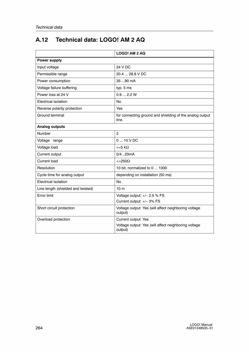
Technical data
264LOGO! Manual
A5E01248535--01
A.12 Technical data: LOGO! AM 2 AQ
LOGO! AM 2 AQ
Power supply
Input voltage 24 V DC
Permissible range 20.4 ... 28.8 V DC
Power consumption 35 ...90 mA
Voltage failure buffering typ. 5 ms
Power loss at 24 V 0.9 ... 2.2 W
Electrical isolation No
Reverse polarity protection Yes
Ground terminal for connecting ground and shielding of the analog outputline.
Analog outputs
Number 2
Voltage range 0 ... 10 V DC
Voltage load >=5 kΩ
Current output 0/4...20mA
Current load <=250Ω
Resolution 10 bit, normalized to 0 ... 1000
Cycle time for analog output depending on installation (50 ms)
Electrical isolation No
Line length (shielded and twisted) 10 m
Error limit Voltage output: +/-- 2.5 % FS
Current output: +/-- 3% FS
Short circuit protection Voltage output: Yes (will affect neighboring voltageoutput)
Overload protection Current output: Yes
Voltage output: Yes (will affect neighboring voltageoutput)

Technical data
265LOGO! ManualA5E01248535--01
A.13 Technical data: CM EIB/KNX
CM EIB/KNX
Mechanical data
Dimensions (WxHxD)
Weight
Installation
36 x 90 x 55 mm
Approx. 107 g
on a 35 mm profile rail2 module widthsor wall mountingmust be mounted as the last module on the right ofLOGO!
Power supply
Input voltage 24 V AC/DC
Permissible range --15% ... +10% AC--15% ... +20% DC
Power consumption from power supply max. 25 mA
Power consumption via bus 5 mA
EIB data transmission rate 9600 baud
Connections
Digital inputs (I) virtual max. 16
Digital outputs (Q) virtual max. 12
Analog inputs (AI) virtual max. 8
Analog outputs (AQ) virtual max. 2
Group addresses max. 56
Associations max. 56
Climatic conditions
Climatic withstand capability EN 50090-2-2
Ambient operating conditions 0 ... 55 ˚C natural convection
Storage and transport temperature -40 ˚C ... +70 ˚C
Relative humidity 95 % at +25 ˚C (not condensing)
Electrical safety
Degree of protection IP 20 (in accordance with EN 60529)
Interference suppression EN 55011 (limit class B)
Certification IEC 60730-1
IEC 61131-2
Overvoltage protection Slow-blowing fuse 80 mA (recommended)
Electromagnetic compatibility (EMC)
EMC requirements Complies with EN 61000-6-1 and EN 61000-6-2
Approval
KNX/EIB certified
UL 508
FM
CE mark
In accordance with the EMC guideline (residential andfunctional buildings), low voltage guideline

Technical data
266LOGO! Manual
A5E01248535--01
A.14 Technical data: CM AS Interface
CM AS Interface
Mechanical data
Dimensions (WxHxD)
Weight
Installation
36 x 90 x 58 mm
Approx. 90 g
on a 35 mm profile rail2 module widthsor wall mountingmust be mounted as the last module on the right ofLOGO!
Power supply
Input voltage 30 V DC
Permissible range 19.2 ... 28.8 V DC
Reverse polarity protection Yes
Total current drain Itot max. 70 mA
Connections
Digital inputs (I) the next four inputs after the physical inputs of LOGO!(In ... In+3)
Digital outputs (Q) the next four outputs after the physical outputs of LOGO!(Qn ... Qn+3)
I/O configuration (hex) 7
ID code (hex) F
ID1 code (hex) F (default, variable from 0 ... F)
ID2 code (hex) F
Bus connection AS interface in accordance with specification
Analog inputs (AI) none
Analog outputs (AQ) none
Climatic conditions
Ambient operating conditions 0 ˚C ... +55 ˚C
Storage temperature -40 ˚C ... +70 ˚C
Electrical safety
Electrical data to AS interface specification
Degree of protection IP 20
Interference suppression Limit class A
Approval
IEC 61131-2
EN 50178
cULus to UL 508
CSA C22.2 No. 142

Technical data
267LOGO! ManualA5E01248535--01
A.15 Technical data: LOGO!Power 12 V
LOGO! Power 12 V is a primary-switched power supply unit for LOGO! devices.Two current ranges are available.
LOGO! Power12 V / 1.9 A
LOGO! Power12 V / 4.5 A
Input data
Input voltage 100 ... 240 V AC
Permissible range 85 ... 264 V AC
Permissible mains frequency 47 ... 63 Hz
Voltage failure buffering > 40 ms (at 187 V AC)
Input current 0.53 ... 0.3 A 1.13 ... 0.61 A
Make current (25˚C) ≤ 15 A ≤ 30 A
Device protection Internal
Recommended circuit breaker(IEC 898) in mains line
≥ 16 A characteristic B≥ 10 A characteristic C
Output data
Output voltageOverall toleranceAdjustment rangeResidual ripple
12 V DC+/--3 %10.5 ... 16.1 V DC< 200/300 mVpp
Output currentOvercurrent limiting
1.9 Atyp. 2.5 A
4.5 Atyp. 5.9 A
Efficiency typ. 80 % typ. 85 %
Parallel circuit for power increase Yes
Electromagnetic compatibility
Interference suppression EN 50081-1, Class B to EN 55022
Interference immunity EN 61000-6-2, EN 61000-4-2/-3/-4/-5/-6/-11
Safety
Electrical isolation,primary/secondary
Yes, SELV (to EN 60950 and EN 50178)
Safety class II
Degree of protection IP 20 (to EN 60529)
CE markingUL/cUL certificationFM approvalGL approval
YesYes; UL 508 / UL 60950Yes; Class I, Div. 2, T4Yes
General details
Ambient temperature range --20 ... +55˚C, natural convection
Storageand shipping temperature --40 ... +70˚C
Connections at input One terminal (1 x 2.5 mm2 or 2 x 1.5 mm2) per L1 and N
Connections at output Two terminals (1x.2.5 mm2 or 2 x 1.5 mm2) per + and --
Installation On 35 mm DIN rail, snap-on
Dimensions in mm (WxHxD) 54 x 80 x 55 72 x 90 x 55
Approx. weight 0.2 kg 0.3 kg

Technical data
268LOGO! Manual
A5E01248535--01
A.16 Technical data: LOGO!Power 24 V
LOGO! Power 24 V is a primary-switched power supply module for LOGO! devices.Two current ranges are available.
LOGO! Power24 V / 1.3 A
LOGO! Power24 V / 2.5 A
Input data
Input voltage 100 ... 240 V AC
Permissible range 85 ... 264 V AC
Permissible mains frequency 47 ... 63 Hz
Voltage failure buffering 40 ms (at 187 V AC)
Input current 0.70 ... 0.35 A 1.22 ... 0.66 A
Inrush current (25˚C) < 15 A < 30 A
Device protection Internal
Recommended circuit breaker(IEC 898) in mains line
≥ 16 A characteristic B≥ 10 A characteristic C
Output data
Output voltageOverall toleranceAdjustment rangeResidual ripple
24 V DC+/- 3 %22.2 ... 26.4 V DC< 200/300 mVpp
Output current
Overcurrent limiting
1.3 A
typ. 2.0 A
2.5 A
typ. 3.4 A
Efficiency > 82 % > 87 %
Parallel circuit for power increase Yes
Electromagnetic compatibility
Interference suppression EN 50081-1, Class B to EN 55022
Interference immunity EN 61000-6-2,EN 61000-4-2/-3/-4/-5/-6/-11
Safety
Electrical isolation,primary/secondary
Yes, SELV (to EN 60950 and EN 50178)
Safety class II
Degree of protection IP 20 (to EN 60529)
CE markingUL/cUL certificationFM approvalGL approval
YesYes; UL 508 / UL 60950Yes; Class I, Div. 2, T4Yes
General details
Ambient temperature range --20 ... +55˚C, natural convection
Storageand shipping temperature --40 ... +70˚C
Connections at input One terminal (1 x. 2.5 mm2 or 2 x 1.5 mm2) per L1 and N
Connections at output Two terminals (1x.2.5 mm2 or 2 x 1.5 mm2) per + and --
Installation On 35 mm DIN rail, snap-on
Dimensions in mm (WxHxD) 54 x 80 x 55 72 x 90 x 55
Approx. weight 0.2 kg 0.3 kg

Technical data
269LOGO! ManualA5E01248535--01
A.17 Technical data: LOGO! Contact 24/230
LOGO! Contact 24 and LOGO! Contact 230 are switching modules for directswitching of ohmic loads up to 20 Amps and motors up to 4 kW (without noiseemission, hum-free).
LOGO!Contact 24
LOGO!Contact 230
Operating voltage 24 V DC 230 V AC;50/60 Hz
Switching capacity
Utilization category AC-1: Switching of ohmic loads at 55˚COperating current at 400 V
Output with three-phase loads at 400 V
20 A
13 kW
Utilization category AC-2, AC-3: Motor with slip ring induction/cagearmature
Operating current at 400 V
Output with three-phase loads at 400 V
8.4 A
4 kW
Short-circuit protection:
Assignment type 1
Assignment type 2
25 A
10 A
Connecting leads Fine-wire with wire end ferrules
Solid wire
2 x (0.75 to 2.5) mm2
2 x (1 to 2.5) mm2
1 x 4 mm2
Dimensions (WxHxD) 36 x 72 x 55
Ambient temperature -25 ... +55˚C
Storage temperature -50 ... +80˚C

Technical data
270LOGO! Manual
A5E01248535--01
A.18 Technical data: LOGO! TD (Text Display)
LOGO! TD
Mechanical data
Dimensions (WxHxD)
Weight
Installation
128.2 x 86 x 38.7 mm
Approx. 220 g
Bracket mounting
Power supply
Input voltage 24 V AC/DC12 V DC
Permissible range 20.4 ... 26.4 V AC10.2 ... 28.8 V DC
Permissible mains frequency 47 ... 63 Hz
Power consumption
• 12 V DC
• 24 V DC
• 24 V AC
typ. 65 mA
typ. 40 mA
typ. 90 mA
LCD Display and Backlight
Backlight lifetime1 20,000 hours
Display lifetime2 50,000 hours
1 Backlight lifetime is defined as: The final brightness is 50% of the original brightness.2 Display lifetime is calculated under ordinary operating and storage conditions: room temperature (20
+/--8˚ C), normal humidity below 65% relative humidity, and not in exposure to direct sunlight.
A.19 Technical data: LOGO! Battery
LOGO! Battery
Manufacturer Panasonic
Type BR1220/1VCE
Voltage 3V
Capacity 35mAh
Mechanical data
Dimensions
Weight
12.5mm x 1.6mm
0.9g

271LOGO! ManualA5E01248535--01
Determining the cycle time
The program cycle is the complete execution of the circuit program, that is,primarily the reading in of the inputs, the processing of the circuit program and thesubsequent reading out of the outputs. The cycle time is the time required toexecute a circuit program once in full.
The time required for a program cycle can be determined using a short testprogram. This test program is created in LOGO! and returns a value during itsexecution in parameter assignment mode from which the current cycle time isderived.
B
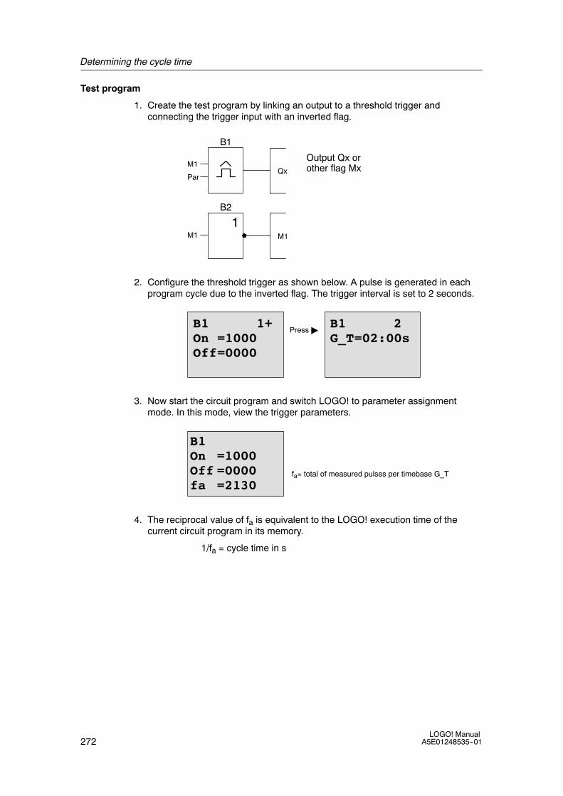
Determining the cycle time
272LOGO! Manual
A5E01248535--01
Test program
1. Create the test program by linking an output to a threshold trigger andconnecting the trigger input with an inverted flag.
ParQx
B1
Output Qx orother flag MxM1
M1M11
B2
2. Configure the threshold trigger as shown below. A pulse is generated in eachprogram cycle due to the inverted flag. The trigger interval is set to 2 seconds.
B1 1+On =1000Off=0000
B1 2G_T=02:00s
Press"
3. Now start the circuit program and switch LOGO! to parameter assignmentmode. In this mode, view the trigger parameters.
B1On =1000Off =0000fa =2130
fa= total of measured pulses per timebase G_T
4. The reciprocal value of fa is equivalent to the LOGO! execution time of thecurrent circuit program in its memory.
1/fa = cycle time in s

Determining the cycle time
273LOGO! ManualA5E01248535--01
Explanation
The inverted flag block changes its output signal at each program execution. Thus,one logic level (high or low) width is exactly equivalent to the length of one cycle.Hence, a period lasts 2 cycles.
The threshold trigger indicates the ratio of periods per 2 seconds, which results inthe ratio of cycles per second.
Edge transition of the inverted flag ateach circuit program execution
Cycle time
Period
1 period = 1 pulse = 2 cycles

Determining the cycle time
274LOGO! Manual
A5E01248535--01

275LOGO! ManualA5E01248535--01
LOGO! without display
Because some specific applications do not require operator control and monitoringunits such as buttons or a display, we provide the LOGO! 12/24RCo, LOGO! 24o,LOGO! 24RCo and LOGO! 230RCo versions without display.
View of a LOGO! 230RCo, for example:
I4 I5 I6
Q1 Q2 Q3 Q4
L1 N
RUN/STOP
I7 I8I1 I2 I3I1 I2 I3I1 I2 I3I1 I2 I3I1 I2 I3I1 I2 I3I1 I2 I3I1 I2 I3
1 2 1 2 1 2 1 2
Less is definitely more!
The versions without display offer you the following benefits:
• Even more cost-effective without the operating element
• Requires less switch cabinet space than conventional hardware
• Substantial benefits with regard to flexibility and prime costs compared tostand-alone electronic switchgear
• Of advantage even for applications in which merely two or three conventionalswitching devices can be replaced
• Very easy to use
• Access protected
• Compatible to LOGO! versions with display
• Offers the option to read data by means of LOGO!Soft Comfort
C

LOGO! without display
276LOGO! Manual
A5E01248535--01
Creating a circuit program without operator panelThere are two ways to create a circuit program for a LOGO! without display:
• You create the circuit program with LOGO!Soft Comfort on your PC and thendownload it to LOGO!(see Chapter 7).
• You download the circuit program from a LOGO! memory card or combinedmemory/battery card to your LOGO! without display(see Chapter 6).
Operating characteristicsLOGO! is ready for operation when power is switched on. Switching off a LOGO!without display is equivalent to disconnecting the power supply, e.g. as if you wereremoving the plug.
The circuit program of LOGO!...o versions cannot be started or stopped by meansof buttons. This is why the LOGO!...o versions have other startup characteristics:
Startup characteristicsIf there is no circuit program in LOGO! or on the inserted memory card or combinedmemory/battery card, LOGO! remains in STOP.
If there is a valid circuit program in LOGO! memory, the LOGO! automaticallyswitches from STOP to RUN when power is switched on.
The circuit program on an inserted memory card or combined memory/battery cardis automatically copied to LOGO!, immediately after power is switched on. Theexisting circuit program in LOGO! memory is overwritten. The system automaticallychanges from STOP to RUN.
Provided the PC cable is connected to LOGO!, you can download the circuitprogram to LOGO! and start it by means of LOGO!Soft Comfort PC software(see Chapter 7.1).
Operating status indicationOperating states, e.g. Power On, RUN and STOP are indicated by an LED on thefront hood.
• Red LED: Power On/STOP• Green LED: Power On/RUNThe red LED is lit after Power On and in all LOGO! states other than RUN. Thegreen LED is lit when LOGO! is in RUN mode.
Reading current dataLOGO!Soft Comfort (see Chapter 7) provides an online test for reading the currentdata of all functions while the system is in RUN.
If your LOGO! without display holds a protected memory card or combinedmemory/battery card, you cannot read the current data unless you enter the correctpassword for the circuit program. The circuit program is otherwise deleted fromLOGO! memory when you remove the memory card or combined memory/batterycard to connect the PC cable. (See Chapter 6.1).
Deleting the circuit programUse LOGO!Soft Comfort to delete the circuit program and password if a passwordexists.

277LOGO! ManualA5E01248535--01
LOGO! menu structure
D.1 LOGO! Basic Module
>StopSet ParamSetPrg Name
>Stop/>Yes
>Memory? Show available memory space (Chapter 3.8)
>AQ
>Edit Name
>Edit Prg Editing the program (Chapter 3.7 cont.)
>Clear Prg
>Password
>Msg Config
>Edit.. Password?
>ProgramCardSetupStart
Programmingmenu (ESC / >Stop >Program)
Menu overview
See “Main menu”
Mo 09:002008-05-26
See “Start menu“
Press ESCNo Program
Circuit program isbusy (RUN)
No Program
Parameter setting (Chapter 5.1.1 cont.)Default values setting (Chapter 5.2 cont.)Display of the program name
>Yes
Parameter assignment menu
Main menu (ESC / >Stop)
See “Programming menu”>Edit..> ->Card>Clock
See “Transfer menu”See “Setup menu”See “Start menu“
Mo 09:002008-05-26
Editing the program name (Chapter 3.7.4)
Selecting analog output values and type(Chapters 3.7.11 and 3.7.12)
Deleting the program (Chapter 3.7.13)
Input/change of password (Chapter 3.7.5)
Configure global parameters for message texts (Chapter 4.4.23)
>ProgramCardSetupStart
D
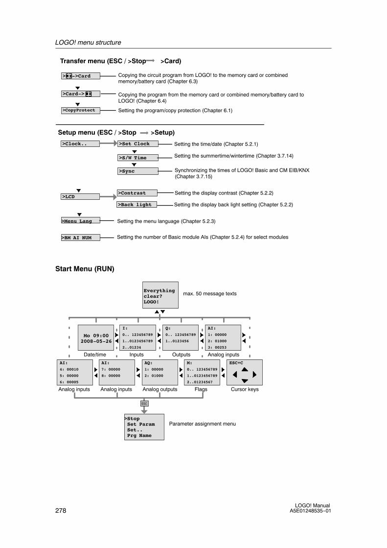
LOGO! menu structure
278LOGO! Manual
A5E01248535--01
>Card->
> ->Card
>CopyProtect
>Clock..
>LCD
>BM AI NUM
>Menu Lang
>Set Clock
>Sync
>S/W Time
>Contrast
>Back light
Transfer menu (ESC / >Stop >Card)
Setup menu (ESC / >Stop >Setup)
Copying the program from the memory card or combined memory/battery card toLOGO! (Chapter 6.4)
Setting the program/copy protection (Chapter 6.1)
Copying the circuit program from LOGO! to the memory card or combinedmemory/battery card (Chapter 6.3)
Setting the summertime/wintertime (Chapter 3.7.14)
Synchronizing the times of LOGO! Basic and CM EIB/KNX(Chapter 3.7.15)
Setting the display contrast (Chapter 5.2.2)
Setting the time/date (Chapter 5.2.1)
Setting the display back light setting (Chapter 5.2.2)
Setting the menu language (Chapter 5.2.3)
Setting the number of Basic module AIs (Chapter 5.2.4) for select modules
Start Menu (RUN)
>StopSet ParamSet..Prg Name
Everythingclear?LOGO!
Mo 09:002008-05-26
Date/time
max. 50 message texts
Inputs
I:0.. 123456789
1..0123456789
2..01234
Cursor keys
Q:0.. 123456789
1..0123456
AI:1: 00000
2: 01000
3: 00253
Outputs Analog inputs
Parameter assignment menu
AI:4: 00010
5: 00000
6: 00005
AI:7: 00000
8: 00000
AQ:1: 00000
2: 01000
M:0.. 123456789
1..0123456789
2..01234567
ESC+C
FlagsAnalog inputs Analog inputs Analog outputs
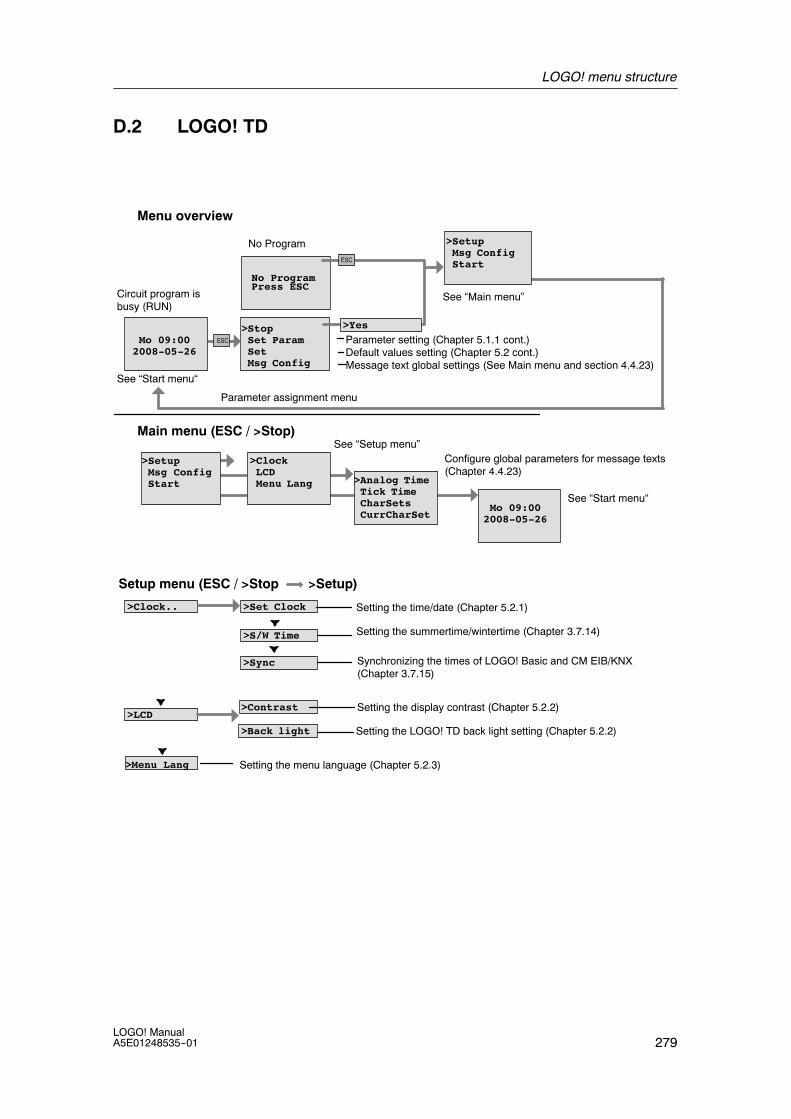
LOGO! menu structure
279LOGO! ManualA5E01248535--01
D.2 LOGO! TD
Press ESCNo Program
>StopSet ParamSetMsg Config
>ClockLCDMenu Lang
>SetupMsg ConfigStart
Menu overview
See “Main menu”
Mo 09:002008-05-26
See “Start menu“
Circuit program isbusy (RUN)
No Program
Parameter setting (Chapter 5.1.1 cont.)Default values setting (Chapter 5.2 cont.)Message text global settings (See Main menu and section 4.4.23)
>Yes
Parameter assignment menu
Main menu (ESC / >Stop)See “Setup menu”
See “Start menu“Mo 09:00
2008-05-26
>SetupMsg ConfigStart
Configure global parameters for message texts(Chapter 4.4.23)
>Analog TimeTick TimeCharSetsCurrCharSet
>S/W Time
>Set Clock
>Sync
>Contrast
>Back light
Setup menu (ESC / >Stop >Setup)
>Clock..
>LCD
Setting the summertime/wintertime (Chapter 3.7.14)
Synchronizing the times of LOGO! Basic and CM EIB/KNX(Chapter 3.7.15)
Setting the display contrast (Chapter 5.2.2)
Setting the time/date (Chapter 5.2.1)
Setting the LOGO! TD back light setting (Chapter 5.2.2)
>Menu Lang Setting the menu language (Chapter 5.2.3)

LOGO! menu structure
280LOGO! Manual
A5E01248535--01
Start Menu (Basic module in RUN)
>StopSet ParamSetMsg Config
Everythingclear?LOGO!
Mo 09:002008-05-26
Date/time
max. 50 message texts
Inputs
I:0.. 123456789
1..0123456789
2..01234
Cursor keys
Q:0.. 123456789
1..0123456
AI:1: 00000
2: 01000
3: 00253
Outputs Analog inputs
Parameter assignment menu
AI:4: 00010
5: 00000
6: 00005
AI:7: 00000
8: 00000
AQ:1: 00000
2: 01000
M:0.. 123456789
1..0123456789
2..01234567
ESC+C
FlagsAnalog inputs Analog inputs Analog outputs
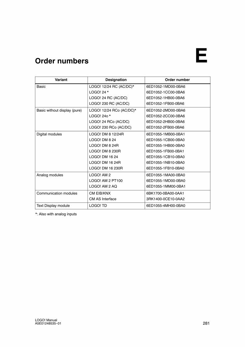
281LOGO! ManualA5E01248535--01
Order numbers
Variant Designation Order number
Basic LOGO! 12/24 RC (AC/DC)*
LOGO! 24 *
LOGO! 24 RC (AC/DC)
LOGO! 230 RC (AC/DC)
6ED1052-1MD00-0BA6
6ED1052-1CC00-0BA6
6ED1052-1HB00-0BA6
6ED1052-1FB00-0BA6
Basic without display (pure) LOGO! 12/24 RCo (AC/DC)*
LOGO! 24o *
LOGO! 24 RCo (AC/DC)
LOGO! 230 RCo (AC/DC)
6ED1052-2MD00-0BA6
6ED1052-2CC00-0BA6
6ED1052-2HB00-0BA6
6ED1052-2FB00-0BA6
Digital modules LOGO! DM 8 12/24R
LOGO! DM 8 24
LOGO! DM 8 24R
LOGO! DM 8 230R
LOGO! DM 16 24
LOGO! DM 16 24R
LOGO! DM 16 230R
6ED1055-1MB00-0BA1
6ED1055-1CB00-0BA0
6ED1055-1HB00-0BA0
6ED1055-1FB00-0BA1
6ED1055-1CB10-0BA0
6ED1055-1NB10-0BA0
6ED1055-1FB10-0BA0
Analog modules LOGO! AM 2
LOGO! AM 2 PT100
LOGO! AM 2 AQ
6ED1055-1MA00-0BA0
6ED1055-1MD00-0BA0
6ED1055-1MM00-0BA1
Communication modules CM EIB/KNX
CM AS Interface
6BK1700-0BA00-0AA1
3RK1400-0CE10-0AA2
Text Display module LOGO! TD 6ED1055-4MH00-0BA0
*: Also with analog inputs
E

Order numbers
282LOGO! Manual
A5E01248535--01
Accessories Designation Order number
Software LOGO!Soft Comfort V6.0
Upgrade to LOGO!Soft Comfort V6.0
6ED1058-0BA02-0YA0
6ED1058-0CA02-0YE0
Memory card LOGO! Memory Card 6ED1056-1DA00-0BA0
Battery card LOGO! Battery card 6ED1 056-6XA00-0BA0
Combined memory/batterycard
LOGO! Combined Memory/Battery Card 6ED1 056-7DA00-0BA0
Switching modules LOGO!Contact 24 V
LOGO!Contact 230 V
6ED1057-4CA00-0AA0
6ED1057-4EA00-0AA0
Power modules LOGO!Power 12V/1.9A
LOGO!Power 12V/4.5A
LOGO!Power 24V/1.3A
LOGO!Power 24V/2.5A
LOGO!Power 24V/4A
LOGO!Power 5V/3A
LOGO!Power 5V/6.3A
LOGO!Power 15V/1.9A
LOGO!Power 15V/4A
6EP1321-1SH02
6EP1322-1SH02
6EP1331-1SH02
6EP1332-1SH42
6EP1332-1SH51
6EP1311-1SH02
6EP1311-1SH12
6EP1351-1SH02
6EP1352-1SH02
Others PC cable
USB PC cable
Modem cable
Manual
6ED1057-1AA00-0BA0
6ED1057-1AA01-0BA0
6ED1057-1CA00-0BA0
6ED1050-1AA00-0AE7
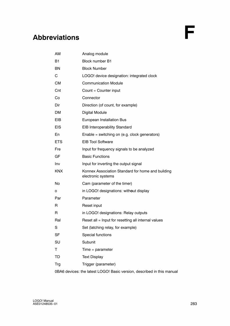
283LOGO! ManualA5E01248535--01
Abbreviations
AM Analog module
B1 Block number B1
BN Block Number
C LOGO! device designation: integrated clock
CM Communication Module
Cnt Count = Counter input
Co Connector
Dir Direction (of count, for example)
DM Digital Module
EIB European Installation Bus
EIS EIB Interoperability Standard
En Enable = switching on (e.g. clock generators)
ETS EIB Tool Software
Fre Input for frequency signals to be analyzed
GF Basic Functions
Inv Input for inverting the output signal
KNX Konnex Association Standard for home and buildingelectronic systems
No Cam (parameter of the timer)
o in LOGO! designations: without display
Par Parameter
R Reset input
R in LOGO! designations: Relay outputs
Ral Reset all = Input for resetting all internal values
S Set (latching relay, for example)
SF Special functions
SU Subunit
T Time = parameter
TD Text Display
Trg Trigger (parameter)
0BA6 devices: the latest LOGO! Basic version, described in this manual
F

Abbreviations
284LOGO! Manual
A5E01248535--01

Index
285LOGO! ManualA5E01248535--01
IndexAAbbreviations, 283AIs in Basic Module, 225AM. See Analog moduleAmplifier, analog, 173Analog
comparator, 165values, 115
Analog amplifier, 173Analog differential trigger, 162Analog math error detection, 212Analog module, 10, 18Analog multiplexer, 194Analog output type, 89Analog output values, 88Analog outputs, 45Analog math, 209Analog ramp, 196Pulse Width Modulator (PWM), 206PWM, 206Analog threshold trigger, 159Analog value monitoring, 170Analog watchdog, 170AND, 106Applications, 241AQ in Stop, 88AQ type, 89AS interface, 11AS interface bus
communication failure, 53communication states, 53connecting, 47networking, 47
Asynchronous pulse generator, 130
BBacklight, 223Backlight flags, 103Backlight lifetime, LOGO! TD, 270Basic functions, 105
AND, 106with edge, 106
NAND, 107with edge, 108
NOR, 109NOT, 111OR, 109XOR, 110
Basics on special functions, 111 Battery, 270
Battery card, 227BF, 101Blank outputs, 56blank outputs, 102Block, 59
deleting, 86block groups, 87
inserting, 82number, 59
assigning, 60BM AI NUM, 225BN, 101
CCap, 30Card. See Program module (card)CE label, 21Certification, 20Ch by Ch ticking, 182Character set flag, 103Character sets, 178Chinese character set, 178Circuit diagram, 62Circuit program, input, 70circuit program, 96
deleting, 90Circuit program name, assigning, 75Circuit program size, 96Circuit programs
archiving, 227reproduce, 227send by mail, 227
Closing the programming mode, 85CM. See Communications moduleCo, 101, 102Combined memory/battery card, 227Communication module
AS interface, 11EIB/KNX, 11
Communication modules, 11Communications module, AS interface, 18Compatibility, Versions, 229Compatiblity, Expansion modules, 28Configuring, EIB bus, 58Connecting
AS interface bus, 47EIB bus, 46Inputs, 38outputs, 44

Index
286LOGO! Manual
A5E01248535--01
Connector, 30Connectors, 56, 102
hi, 57inputs, 57lo, 57LOGO!’s, 57open, 104outputs, 57unused, 57, 63x, 57, 63, 112
Constants, 102Control panel, 13, 14Conversion, Summertime and wintertime, 91Correcting typing errors, 88Counter
Operating hours, 152Up/down, 149
CSA, 20cULus , 20Cursor, 65Cursor keys, 56, 104, 187Cursor movement, 65Cycle time, 271
DDefault values, 221Demo versions, 238Detection of math error, Analog amplifier, 212Device types, LOGO!, 10Digital module, 10, 18Dimensions, 29DIN rail, 29Display, 60Display contrast, 223Display lifetime, LOGO! TD, 270Display modules, 10Display view, 60Disposal, 21Divide by 0 error, 212DM8.... See Digital module
EEarth connection, 36Edge evaluation, 106, 108Editing, 81EIB bus
communication failure, 53communication states, 53configuring, 58connecting, 46networking, 46
EIB/KNX, 11
Errors, analog math, 212exclusive OR, 110Expansion modules, 10, 56
Analog, 10analog, 57digital, 10, 57operating state, 52
FFlag blocks, 103FM, 20Four golden rules, 64Function blocks, 59Function keys, 10Functions, 101
GGain, 115GB--2312, 178GF, 105Golden rules, 64Guidelines, 23
HHiding, 84high--speed counting, 40Hours counter, 152
Reading the MN and OT values, 154Hysteresis, 169
IInputs, 102
Analog inputs, 40, 102connection, 38Cursor keys, 56, 104Digital Inputs, 102Groups, 38inverting, 73, 105, 117LOGO! TD function keys, 56unused, 63
inputs, High--speed inputs, 40Inserting, 82Installation guidelines, 23Installing, LOGO! TD, 34Interlock, 32Internet address, 4Inverter, 111ISO8859--1, 178ISO8859--16, 178

Index
287LOGO! ManualA5E01248535--01
ISO8859--5, 178ISO8859--9, 178
LLabeling, 35Language, menu, 224Latching relay, 174LCD, 13, 14LCD lifetime, LOGO! TD, 270LED, 276Levels, 104List
BF, 101BN, 101Co, 101, 102SF, 101, 117
List , GF, 105Ln by Ln ticking, 183Logic module, 9Logical inputs, 112LOGO!
connecting to PC, 239guidelines, 23identifying, 17Installing, 29labeling, 35memory and battery cards, 227menus, 66, 277operating states, 52removing, 29software, 237structure of, 13switching on, 49versions, 19wiring, 35without display, 275
LOGO! TD, 10Backlight lifetime, 270Display lifetime, 270function keys, 10installing, 34menus, 279power supply, 37power--up screen, 10display, 20voltage, 20
LOGO!Soft Comfort, 238
MMath error, analog, 212
Memoryareas, 96free, 100limitation, 96requirements, 97space, 96
Memory card, 227Card ----> LOGO, 236CopyProtect, 231LOGO ----> Card, 234
Memory/battery card, 227Menu language, 224Menu structure
LOGO!, 277LOGO! TD, 279
MenusMain menu, 66Parameter assignment menu, 66Programming menu, 66Setup menu, 66Transfer menu, 66
Message text charset flag, 103Message texts, 177
character set, 178Message ticking, 182Mode
parameter assignment, 66, 216PC--LOGO, 239programming, 66
Modems, 4Mounting
DIN rail mounting, 30Drilling template, 33LOGO! TD, 34Wall--mounting, 33
Multiple function switch, 136
NName, 75NAND, 107Negation, 111
of a BF input, 105of an input, 73of an SF input, 117
NetworkingAS interface bus, 47EIB bus, 46
NOR , 109NOT , 111NOT OR, 109Number of AIs, 225
Index
288LOGO! Manual
A5E01248535--01
OOff--delay, 123Off--time, 141Offset, 115On--/Off--delay, 124On--delay, 120
retentive, 126On--time, 141Open connectors, 104Operating
characteristics, 276Status indication, 276
Operating modeChanging the operating mode, 64Programming mode, 67
OR, 109Order numbers, 281Outputs, 102
Analog outputs, 103blank, 56, 102connecting, 44Digital outputs, 102
Overflow error, 212
PParameter, 217
Inputs, 112selecting, 218Set Param, 217setting, 215T, 113
Parameter assignment, 83Parameter assignment menu, 216Parameter assignment screen form, 140, 181Parameter protection, 114Parameters, modifying, 219parameters, showing/hiding, 84Password
assigning, 76changing, 77deactivating, 78wrong, 78
PC cable, 239USB, 239
PC--LOGO, 239PI controller, 200Planning, 65Power, on/off, 49Power supply
connecting, 35LOGO! TD, 37
Program memory, 96Program chart, 61
Program cycle, 271Program module (card)
copying, 235Enabling the security function, 231inserting, 232, 233removing, 232, 233Security function, 230
Program namechange, 75character set, 75read, 217
Programming menuAQ in Stop, 88AQ type, 89Clear Prg, 90Edit Name, 75Edit Prg, 68Password, 76
Programs, modifying, 81Protection mode, 84Pulse
Pause, 129width, 129
pulse generator, Asynchronous , 130Pulse output, 127Pulse relay, 175
RRandom generator, 132Recycling, 21Relay outputs, 44, 261
service life, 261switching capacity, 261
Removal, 32Resources, 97Retentive memory, 96Retentive on--delay, 126Retentivity, 114
enabling/disabling, Retentivity setting, 84Rules, four golden, 64RUN mode, 79
SSensor Characteristics, 38Sensor connections, 41Set clock, 222Setting
Default values, 221Display contrast, 223, 224, 225Start screen, 226time, 84Time--of--day and date, 222
Index
289LOGO! ManualA5E01248535--01
Setting the date, 221, 222Setting the time--of--day, 222Settings, 217Setup, 25
Maximum setup, 25with different voltage classes, 27
SF, 101, 117SFs, Delay, On, 120Shift register, 192Shift register bits, 56, 104Showing, 84Signal status transitions, 39Simulation, 237Softkey, 189Software, 237Solid--state outputs, 44
Special functions, 117Analog amplifier, 173Analog comparator, 165Analog differential trigger, 162Analog math error detection, 212Analog multiplexer, 194Analog math, 209Analog ramp, 196Pulse Width Modulator (PWM), 206Analog threshold trigger, 159Analog value monitoring, 170Analog watchdog, 170Basics, 111Counter
Hours counter, 152Up/down, 149
DelayOff, 123On/Off, 124
Message texts, 177PI controller, 200Pulse generator, asynchronous, 130Random generator, 132Relay
latch, 174pulse, 175
Retentive On--delay, 126Shift register, 192Softkey, 189Switch
Comfort, 136Stairway lighting, 134
Threshold trigger, Frequency, 156Timer
Week, 139Year, 143
Trigger, Analog threshold, 159Wiping relay
edge triggered, 128Pulse output, 127
Stairway lighting switch, 134Start, 79Start screen, 226Startup characteristics, 276Startup flag, 103Stop, 216Subunits, 29Summertime, 91Summertime/wintertime conversion, 91, 221
Clock, 91disabling, 95enabling, 92S/W Time, 91user--define parameters, 94

Index
290LOGO! Manual
A5E01248535--01
SwitchMultiple function, 136Stairway lighting, 134
Switched current, maximum, 45Symbols, 17Synchronization, 95, 221
Clock, 95enabling, 96Sync, 95
TT, Parameter, 113Technical data, 245
CM AS interface, 266CM EIB/KNX, 265general, 245LOGO! 12..., 259LOGO! 230...., 247LOGO! 24/24o, 251LOGO! 24RC/24RCo, 255LOGO! AM 2, 262LOGO! AM 2 AQ, 264LOGO! AM 2 PT100, 263LOGO! Battery Card, 270LOGO! DM16 230R, 249LOGO! DM16 24, 253LOGO! DM16 24R, 257LOGO! DM8 12/24R, 259LOGO! DM8 230R, 249LOGO! DM8 24, 253LOGO! DM8 24R, 257LOGO! TD, 270LOGO!Contact, 269LOGO!Power 12 V, 267
Text Display (TD), 10Threshold trigger, Frequencies, 156Ticker, 182Time, Accuracy of, 113Time response, 113Timebase, 83, 113, 120Timer, 9
accuracy, 113Timing inaccuracy , 113Trigger
Analog differential, 162Analog threshold, 159
UUnderflow error, 212Unused connectors, 57, 63Unused inputs, 63Up/down counter, 149Upgrade, 238Upward compatibility, 229URL, 4USB, 239
VVerification, 85Voltage levels , 104Voltage supply, connecting, Circuit protection,
36
WWeekday, 140Weekly timer, 17, 139, 141
Examples, 141setting, 141
Wintertime, 91Wiping relay
edge triggered, 128Pulse output, 127
Wire ferrules, 35without display
PC--LOGO mode, 239reading current data, 276
XXOR , 110
YYearly timer, 143
ZZero division error, 212Zero offset, 115