Logic Controller N. Elias and N. M. Yahya ABSTRACT
12
International Journal of Automotive and Mechanical Engineering ISSN: 2229-8649 (Print); ISSN: 2180-1606 (Online) Volume 15, Issue 4 pp. 5989-6000 Dec 2018 © Universiti Malaysia Pahang, Malaysia 5989 Simulation Study for Controlling Direct Current Motor Position Utilising Fuzzy Logic Controller N. Elias * and N. M. Yahya Faculty of Manufacturing Engineering, Universiti Malaysia Pahang, 26600 Pekan, Pahang, Malaysia * Email: [email protected] Phone: +601397972754; Fax: +6094245888 ABSTRACT A fuzzy logic controller (FLC) modelled with MATLAB toolbox that is implemented for position control of a direct current (DC) motor is presented in this paper. The position control is an adaptation of an assisted lifting device system. Due to the existing assisted lifting device problems that lift the load slowly and having lack of accuracy, this research is conducted to improve current assisted lifting device with the introduction of a DC motor and a fuzzy logic controller (FLC) that can improve position accuracy, especially when loading the loads. The DC motor was modelled, converted to a subsystem in Simulink and then the MATLAB toolbox is used to design the FLC. The methodology covers the simulation and modelling of the DC motor, fuzzy logic controller and different transfer functions for DC motor model as a benchmark to the performance of the fuzzy system. The outcomes acquired from the scope of the simulation was analysed. Parameters such as the rise and settling time in seconds and maximum overshoot in percentage are observed to be compared with different types of transfer functions that are used for the dynamic response of the closed-loop system and system with and without a controller that was used as references. The overall performance shows that a system with FLC performs well compared to the system without FLC. Keywords: Fuzzy logic; position control; DC motor; transfer function; Simulink. INTRODUCTION The electric device that converts electrical energy into mechanical energy is known as electric motor. Alternating Current (AC) sources such as generators, power grid, or inverters, or Direct Current (DC) sources, such as from rectifiers and batteries are used for the functioning of the electric motor [1]. A DC motor has been selected as the platform to do the experiment because the position and speed are needed especially in electronic devices, manufacturing applications, and automated utilisation. The DC motor can be controlled by a wide range of devices, making DC motor application development relatively accessible and flexible. It also has speed variation and torque [1]. DC motor may be a brushed or brushless, but brushless DC motor is chosen in this study because current, voltage, torque and rpm are linearly related. Other than that, the brushless DC motor can eliminate ionizing sparks, has a long operating life and noiseless operation, as well as high in efficiency and speed ranges [2]. The range for simulating the study is by mimicking the position control of the assisted lifting device. With advances in computational capability, sensing and also control technology, assisted lifting device is introduced to eliminate these highly
Transcript of Logic Controller N. Elias and N. M. Yahya ABSTRACT
International Journal of Automotive and Mechanical Engineering
ISSN: 2229-8649 (Print); ISSN: 2180-1606 (Online)
Volume 15, Issue 4 pp. 5989-6000 Dec 2018
© Universiti Malaysia Pahang, Malaysia
5989
Simulation Study for Controlling Direct Current Motor Position Utilising Fuzzy
Logic Controller
N. Elias* and N. M. Yahya
Faculty of Manufacturing Engineering, Universiti Malaysia Pahang,
26600 Pekan, Pahang, Malaysia *Email: [email protected]
Phone: +601397972754; Fax: +6094245888
ABSTRACT
A fuzzy logic controller (FLC) modelled with MATLAB toolbox that is implemented for
position control of a direct current (DC) motor is presented in this paper. The position
control is an adaptation of an assisted lifting device system. Due to the existing assisted
lifting device problems that lift the load slowly and having lack of accuracy, this research
is conducted to improve current assisted lifting device with the introduction of a DC
motor and a fuzzy logic controller (FLC) that can improve position accuracy, especially
when loading the loads. The DC motor was modelled, converted to a subsystem in
Simulink and then the MATLAB toolbox is used to design the FLC. The methodology
covers the simulation and modelling of the DC motor, fuzzy logic controller and different
transfer functions for DC motor model as a benchmark to the performance of the fuzzy
system. The outcomes acquired from the scope of the simulation was analysed.
Parameters such as the rise and settling time in seconds and maximum overshoot in
percentage are observed to be compared with different types of transfer functions that are
used for the dynamic response of the closed-loop system and system with and without a
controller that was used as references. The overall performance shows that a system with
FLC performs well compared to the system without FLC.
Keywords: Fuzzy logic; position control; DC motor; transfer function; Simulink.
INTRODUCTION
The electric device that converts electrical energy into mechanical energy is known as
electric motor. Alternating Current (AC) sources such as generators, power grid, or
inverters, or Direct Current (DC) sources, such as from rectifiers and batteries are used
for the functioning of the electric motor [1]. A DC motor has been selected as the platform
to do the experiment because the position and speed are needed especially in electronic
devices, manufacturing applications, and automated utilisation. The DC motor can be
controlled by a wide range of devices, making DC motor application development
relatively accessible and flexible. It also has speed variation and torque [1]. DC motor
may be a brushed or brushless, but brushless DC motor is chosen in this study because
current, voltage, torque and rpm are linearly related. Other than that, the brushless DC
motor can eliminate ionizing sparks, has a long operating life and noiseless operation, as
well as high in efficiency and speed ranges [2].
The range for simulating the study is by mimicking the position control of the
assisted lifting device. With advances in computational capability, sensing and also
control technology, assisted lifting device is introduced to eliminate these highly

Simulation Study for Controlling Direct Current Motor Position Utilising Fuzzy Logic Controller
5990
repetitive lifting of heavy awkward loads and unnatural motions [3]. Assisted lifting
devices are increasingly being used around the world to assist industrial workers
especially in material handling system (MHS) environments [4]. The assisted lifting
devices address the need for a solution that bridges the limitation of conventional MHS
and the high capital costs of robots in industrial environments. The most typical kinds of
assisted lifting device that is used to lift loads on an adjustable height thus reducing the
risk of a repetitive stress injury and bringing the loads into the power zone are hydraulic
lift tables, pneumatic lift tables, and ball screw lift tables [5]. Pneumatic lift tables are
powered by an air compressor to transport goods for ease of loading and unloading [6]. It
usually uses several kinds of airbag; either one, two, or multiple relying upon the capacity
and its application. The pneumatic lift tables are commonly applied in light-duty
operations with lower maximum capacity, where a large vertical lift is required, or if the
exact placement is demanded [6]. The ball screw scissor lift table requires an electric
motor that shifts a horizontal or vertical ball screw that mobilises the scissors and platform
up and down [7]. Hydraulic lift tables which are most widely available in the market are
known to adjust the height of an object to enable a standing person to easily handle the
object. The lifting table includes bottom and top platforms with a scissors link mechanism
connecting with the straight movement whether upward or downward of the top platform
[8].
The hydraulic lift table functions when pressurised hydraulic fluids power a linear
actuator to raise the table. Therefore, an accompanying hydraulic pump is required. A
hydraulic cylinder activates the lift platform inserted in the centre of a pair of parallel
shafts located at the upper and lower part. The lift table offers the mechanical upward and
downward motion in a vertical plane [9]. The lift table brings the loads closer to the
worker and thus reduces reaching and back flexion. However, in operations that demand
accurate and exact positioning despite the load, the hydraulic lift tables are either
awkward to move at the needed height or have too much “bounce” when loads are being
altered or switched [10]. Besides that, there is also a 3-axis assisted device that is capable
to guide human motions via virtual surfaces. Virtual surfaces are like rulers, user-
programmable and multi-dimensional [11]. The multi-axes (x, y, and z) use a servo-
operated trolley to move the assisted lifting device. Therefore, the workers should be
designated in which direction the loads are moving and then the system will provide force
to speed up and slow down the device [11]. Either one or two axes could be powered, as
needed. However, the time needed to speed up and slow down the assisted lifting device
increases the cycle times, especially when accurate positioning is demanded [12]. Besides
that, the device collisions are a major problem when the device is powered by the actuator
because the worker needs to operate the device at a higher speed. The classical repulsive
algorithm to avoid collisions was discovered to be unstable in the multi-axis lifting device
[13]. Other than that, a Four-Degree of Freedom (DOF) heavy-lift assist device is one of
the existing assisted lifting devices. The elbow, base, and wrist DOF are powered by DC
servomotors to reduce the physical labour required by the operator while operating the
device. Closed loop control is applied to operate the manipulator [14]. Multi-axis motion
control board is used to direct the servomotors. But, due to the controller problem, the
position of the lift assist device is not accurate. The time delays, nonlinearities and high
orders make it difficult to tune the PID gains properly.
While such existing lifting table performs quite satisfactorily, a more ergonomic
and intelligent alternative is frequently needed. Hydraulic lift table is chosen compared
to other assisted lifting device because of the stability and simple to assemble [15]. The
existing hydraulic lift table still lifts slowly especially during the loading process [16].

Elias & Yahya / International Journal of Automotive and Mechanical Engineering 15(4) 2018 5989-6000
5991
The hydraulic lift table also lifts slowly when a weightier load is placed on it. Some of
the lift tables also did not lift the right adjusting height. So, due to the existing hydraulic
lift table problems that lift the load slowly and not having position accuracy, this research
is done to improve the existing hydraulic lift table with an introduction of the fuzzy logic
controller (FLC) into the DC motor that can boost speed and also improve position
accuracy, especially when loading the loads. By using the controller, the position can be
adjusted until it gets like the desired output that user needs. Fuzzy logic is reviewed as
the substitute for typical control theory in the complex nonlinear plants in control system
since the exact mathematical modelling is hard and problematic [17]. The mathematical
modelling is unnecessary for designing of the controller because it is one of the superior
features of fuzzy logic compared to the traditional control approach. The control rules are
stationed fundamentally on knowledge of the system behaviour and the experience of the
control engineer. Considering that the fuzzy logic controller demands simple
mathematical works compared to other classical controllers, its application needed low-
speed processors.
Therefore, for this research, MATLAB/Simulink is chosen as a platform to
simulate and design the fuzzy logic controller. The simulation of a different model of DC
motor is part of this study so that it differentiated based on the performance. The novelty
of this research compared to others is that the fuzzy logic controller designed is compared
with different types of transfer function for the DC motor, and the controller uses the
centroid method to be optimised.
MATERIAL AND METHOD
In order to achieve the research objective, the flow of work must be planned. The research
methodology can be divided into 2 phases. The first phase involved the design of the
fuzzy logic controller (FLC). The second phase is the simulation of proposed FLC on
DC motor position control. The results of the simulations are elaborate and discussed in
the Result section. The types of response that are considered is the response to sudden
load increment and also decrement.
Fuzzy Logic Controller
A fuzzy logic controller (FLC) has four crucial elements that need to be implemented,
namely fuzzification, inference mechanism, rule base and defuzzification [18]. The
controller functioning and also membership function structure plays an important role as
the number of fuzzy sets that establish linguistic variables, mapping of the measurements
onto the support sets and regulation of protocol. Thus, the tuning of FLC can be done by
altering the parameters and also replacing the membership functions or the designing
rules [19]. The FLC is designed in the Matlab toolbox and then was called back in the
Simulink. The name of the FLC that is built in the Matlab toolbox must be the same as in
the Simulink.
Fuzzy logic controller (FLC) is an example of control methods known as the
multi-rule-based variable’s consideration. This method gives quicker outcomes when
comparing to other traditional and conventional control methods such as Proportional-
Integral-Derivative (PID) and Neural Networks. Being nimble and steadfast are the main
reasons for selecting FLC in controlling the intent in the recent study. Compared to any
other controller, FLC required some inputs to develop some control signal. For this
research, there are two inputs and one output. The inputs of FLC, namely an error (e) and

Simulation Study for Controlling Direct Current Motor Position Utilising Fuzzy Logic Controller
5992
change of error (ce), are selected based on the variances in position. The parameters
chosen is based on the minimisation of error for the input so that the reference’s value
that was inserted can be plus or minus in getting more accurate position, and also to
improve robustness of the overall system. Equations (1) and (2) indicate the selected
inputs for the FLC system.
e (t) = wref- wmeasured
wref
(1)
ce (t) = ∆ e(t)
∆t = e(t) – e (t-1)
(2)
To implement the FLC in a problem, different steps of this rule based must be
taken as follows:
i. Fuzzification: The input constructed in the Matlab toolbox needed to be fuzzified
by the membership functions. The membership function gives a value of μ to each
of the input values. The centroid method was picked for building the required
triangle type of the membership function. The variables for input and output for
the FLC consist of seven fuzzy sets, namely NL (negative large), NM (negative
medium), NS (negative small), ZE (zero), PS (positive small), PM (positive
medium) and PL (positive large).
ii. Inference diagram: According to Mamdani [18], the rule base should be tested
into the membership function that has been achieved. The rule table is tabulated
and shown in Table 1. The surface viewer also can be attained when MATLAB
FLC Inference is applied.
Table 1. Rules table of the fuzzy logic controller.
𝑐𝑒 ∆ e
NL NM NS ZE PS PM PL
NL NL NL NL NL NM NS ZE
NM NL NL NL NM NS ZE PS
NS NL NL NM NS ZE PS PM
ZE NL NM NS ZE PS PM PL
PS NM NS ZE PS PM PL PL
PM NS ZE PS PM PL PL PL
PL ZE PS PM PL PL PL PL
DC Motor Model
A DC motor is generally adopted in the control system process due to advantages such as
preciseness, smooth application, faster adaption, electrically efficient and high-power
density [20]. DC motors are superb for many adjustable position controls and also
purposely applied in a broad area of position drivers. A superb position control system
makes the DC motor applicable in adjustable position variations, for example in this study
as assisted lifting devices that are mostly used in the manufacturing industry. The DC
motor is designed using the Simulink block diagram.

Elias & Yahya / International Journal of Automotive and Mechanical Engineering 15(4) 2018 5989-6000
5993
For this study, three different transfer functions are used for representing the motor
model. The main reasons for the difference are the model of DC motor and also the
parameter that is used. In armature control of separately excited DC motors, the voltage
used for the motor armature is adjusted without changing the voltage applied to the field.
Figure 1 shows the same model of a separately excited DC motor.
Figure 1. DC motor model.
The relation between rotor shaft speed and applied armature voltage is represented
by the transfer function:
W(s)
Va(s)=
KT
La. Jm.s2+(Ra. Jm+ La. Bm).s+ (Ra. Bm+ Kb. KT)
(3)
The relation between position and speed is given in Eq. (4). Then the transfer
function between shaft position and armature voltage at no load is in Eq. (5).
θ (s)=1
s W(s)
(4)
θ(s)
Va(s)=
KT
La. Jm.s3+(Ra. Jm+ La. Bm).s2+ (KT.Kb+ Ra. Bm). s
(5)
where va= armature voltage (V), Ra= armature resistance (Ω), La= armature inductance
(H), Ia = armature current (A), Eb= back emf (V), w = angular speed (rad/s), Tm= motor
torque (Nm), ᶿ = angular position of rotor shaft (rad), Jm= rotor inertia (kgm2), Bm=
viscous friction coefficient (Nms/rad), KT= torque constant (Nm/A) and Kb= back emf
constant (Vs/rad).
RESULTS AND DISCUSSION
When the fuzzy logic controller is fully constructed, and a 3D input-output is achieved
from the Surface Viewer, the MATLAB Simulink model has been built for simulating the
fuzzy logic controller and evaluating the performance of the system. The rules that set in
the fuzzy logic controller act as a “brain” – controller for the whole system. The
performance of the designed system was simulated throughout the output Scope of the
Simulink model. The fuzzy logic controller blocks existed in MATLAB Simulink
Library. The output actuator in the Simulink model used was the DC motor. The DC
motor transfer function that is used in the Simulink model represents the output actuators.
Simulation Study for Controlling Direct Current Motor Position Utilising Fuzzy Logic Controller
5994
The result from scope were compared either by using the controller or without the
controller for both transfer functions. The first transfer function was in 1-in 1-out
subsystem while for the other transfer function was 2-in 2-out subsystem used for the DC
motor position control. Finally, the transfer function that is mostly used for the DC motor
was simulated.
1-in 1-out Subsystem
The performance of the system was evaluated by the simulation results from MATLAB
Fuzzy Logic Toolbox and MATLAB Simulink. For the first block diagram, a 1-in 1-out
subsystem is used for the DC motor block diagram. The system is named as Motor_pos1
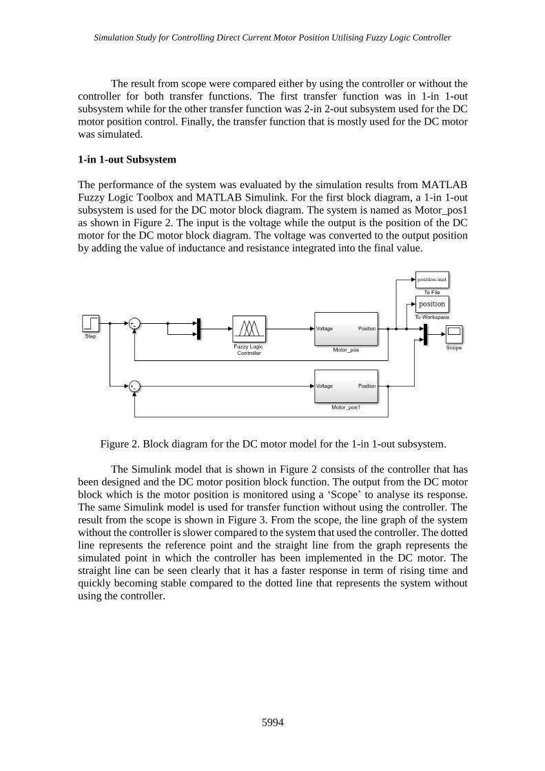
as shown in Figure 2. The input is the voltage while the output is the position of the DC
motor for the DC motor block diagram. The voltage was converted to the output position
by adding the value of inductance and resistance integrated into the final value.
Figure 2. Block diagram for the DC motor model for the 1-in 1-out subsystem.
The Simulink model that is shown in Figure 2 consists of the controller that has
been designed and the DC motor position block function. The output from the DC motor
block which is the motor position is monitored using a ‘Scope’ to analyse its response.
The same Simulink model is used for transfer function without using the controller. The
result from the scope is shown in Figure 3. From the scope, the line graph of the system
without the controller is slower compared to the system that used the controller. The dotted
line represents the reference point and the straight line from the graph represents the
simulated point in which the controller has been implemented in the DC motor. The
straight line can be seen clearly that it has a faster response in term of rising time and
quickly becoming stable compared to the dotted line that represents the system without
using the controller.

Elias & Yahya / International Journal of Automotive and Mechanical Engineering 15(4) 2018 5989-6000
5995
Figure 3. Step response results for Simulink model without and with a fuzzy logic
controller.
2-in 2-out Subsystem
For the second block diagram, a 2-in 2-out subsystem is used for the DC motor block
diagram. The system is named as DC Motor as shown in Figure 4. The input ports were
armature voltage, Va, and load torque, Tload, while the output ports are angular speed, w,
and position , θ. For the load torque, the value is zero since the response for the speed was
ignored because the aim for the research is only to get the response from the position.
Figure 4. Block diagram for the DC motor model for the 2-in 2-out subsystem.
The results for the step response for the Simulink model that used 2-in 2-out
subsystem is shown in Figure 5. The dotted line from the graph represents the reference

Simulation Study for Controlling Direct Current Motor Position Utilising Fuzzy Logic Controller
5996
point while the straight line is the desired point which is the DC motor that has been
implemented with the fuzzy logic controller. The amplitude for the dotted line is bigger
compared to the amplitude in the straight line of the graph. Therefore, the curve of the
dotted line is less steep compared to the curve in the straight-line graph. The steeper the
graph means that the rise time is faster compared to the less steep one. The obtained result
is important since it clearly shows that the system without the controller that is
represented by dotted line has less response compared to the system that used the
controller which is represented by the straight line.
Figure 5. Step response results for Simulink model without and with a fuzzy logic
controller
Typical Type of DC Motor Transfer Function
For the third block diagram, a commonly used transfer function for the DC motor block
diagram is chosen. The system is named as DC Position Motor as shown in Figure 6. The
motor parameters in the transfer function are achieved from the armature resistance,
armature inductance, torque constant, and rotor inertia of the typical brushless DC motor
A2208. All values are obtained from the product specifications of the brushless DC motor.
Figure 6. Block diagram for the DC motor model for the typical brushless DC motor

Elias & Yahya / International Journal of Automotive and Mechanical Engineering 15(4) 2018 5989-6000
5997
The results for the step response for the Simulink model that used a typical DC
motor is shown in Figure 7. The dotted line from the graph represents the reference point
while the straight line is the desired point in which the DC motor has been implemented
with a fuzzy logic controller. The line that represents the system that used the controller
becomes faster in stationary state compared to the dotted line that represents the system
without using the controller. Although there is an overshoot in the system that used the
controller, the time to raise the response is faster compared to the system without the
controller.
Figure 7. Step response results for Simulink model without and with a fuzzy logic
controller.
Comparative Results
The simulated results were interpreted as shown in Table 2. The values of the response
parameters such as rise time, settling time and percentage overshoot are tabulated. The
simulation results show that the subsystems that used fuzzy logic controller have faster
response than the system without a controller, which was expected. However, the system
without a controller works better than the system that used a controller in terms of having
lower overshoot. Since overshoot is important to achieve better rising time and speed up
the performance, the value is neglected. The most important part to be observed is the rise
time and the settling time. For the three different transfer functions of the DC motor
position control block, the values of rising time and settling time for the system using the
fuzzy logic controller is less compared to the system that does not use the controller.
Conclusively, the fuzzy logic controller reduced rise time, increased the overshoot and
decreased the settling time by a small amount.

Simulation Study for Controlling Direct Current Motor Position Utilising Fuzzy Logic Controller
5998
Table 2. Simulation results comparison.
Metrics Values
Controller
1-in 1-out subsystem 2-in 2-out subsystem A typical DC motor
Without
controller
Fuzzy
logic
controller
Without
controller
Fuzzy
logic
controller
Without
controller
Fuzzy
logic
controller
Rise time
(s) 0.07 0.05 0.13 0.11 0.07 0.06
Settling
time (s) 0.19 0.17 0.60 0.50 0.19 0.16
Overshoot
(%) 0.08 0.20 0 0 0.1 0.20
CONCLUSION
The objective of this study was achieved as the fuzzy logic controller (FLC) that was
designed performed well depending on the demand from a user (fuzzy rules) and can be
simulated for different types of transfer functions. For the 1-in 1-out subsystem and
typical DC motor transfer function, although the percentage of overshoot is higher, the
time of rising and settling that represents the system with the fuzzy logic controller is
faster compared with the one without using the controller. The overall performance in
rising time, settling time and having no overshoot for the 2-in 2-out subsystem is better
for the system using the controller compared to the system without using the controller.
The output actuators motor’s position with a fuzzy logic controller is accomplished with
good performance, steady and precise as the desired set point compared to the system
without using the fuzzy logic controller. Despite the better performance achieved, there
are still some improvements that can be done to obtain better results. For this reason,
some recommendations are added to establish better results and improve future works.
An experimental work which includes a controller’s prototype in a real condition for
assisted lifting device should be developed. The limitation of this study is not having real
data analysis for the DC motor position control for assisted lifting devices. Thus, it is
recommended that future work be done combining simulation and actual experiments to
achieve better results.
ACKNOWLEDGEMENT
This research is funded by the University Malaysia Pahang under research grant
RDU180386. The authors would like to thank University Malaysia Pahang for
encouraging this research.
REFERENCES
[1] Namzov M, Basturk O. DC motor position control using fuzzy proportional-
derivative controllers with different defuzzification method. Official Journal of
Turkish Fuzzy System Association 2010; 1(1): 36-54.
[2] Nasser T. Design and Applications of Fuzzy Logic for the Speed Control of a
Direct-Drive DC Motor. In: 4th International Conference on Control and Systems,
Amman, Jordan, pp. 117-212; 2002.

Elias & Yahya / International Journal of Automotive and Mechanical Engineering 15(4) 2018 5989-6000
5999
[3] Burnfield JM, Shu Y, Buster TW, Taylor AP, McBride MM, Krause ME.
Kinematic and electromyographic analyses of normal and device-assisted sit-to-
stand transfers. Gait & posture. 2012; 36(3): 516-22.
[4] Frost DM, Abdoli-EM, Stevenson JM. PLAD (personal lift assistive device)
stiffness affects the lumbar flexion/extension moment and the posterior chain
EMG during symmetrical lifting tasks. Journal of Electromyography and
Kinesiology. 2009; 19(6): 403-12.
[5] Gupta AK, Arora SK. World-class warehousing and material handling. Industrial
automation and robotics. New Delhi: Laxmi Publication; 2009.
[6] Keir PJ, MacDonell CW. Muscle activity during patient transfers: a preliminary
study on the influence of lift assists and experience. Ergonomics. 2004; 47(3):296-
306.
[7] Zhang W, Zhang C, Zhao J, Du C. A Study on the Static Stability of Scissor Lift.
The Open Mechanical Engineering Journal. 2015: 954-60.
[8] Horino S. Environmental factors and work performance of foundry workers.
Journal of human ergology. 1977; 6(2): 159-66.
[9] Corrado A, Polini W, Canale L, Cavaliere C. To design a belt drive scissor lifting
table. International Journal of Engineering and Technology. 2016; 8(1): 515–525.
[10] Majewski M, Kacalak W. Smart control of lifting devices using patterns and
antipatterns. In Computer Science On-line Conference, pp. 486-493; 2017.
[11] Miądlicki K, Pajor M. Overview of user interfaces used in load lifting devices.
International Journal of Scientific & Engineering Research. 2015; 6(9):1215-20.
[12] Naito K, Kanno T, Miyazaki T, Kawashima K. Development of minimally
invasive lifting device using extension and flexion of pneumatic soft actuator for
laparoscopic surgery. InSystem Integration (SII), 2017 IEEE/SICE International
Symposium, pp. 565-570; 2017.
[13] Campeau-Lecours A, Foucault S, Laliberté T, Mayer-St-Onge B, Gosselin C. A
cable-suspended intelligent crane assist device for the intuitive manipulation of
large payloads. 2016; 21(4): 2073-2084.
[14] Flores-Morán E, Yánez-Pazmiño W, Barzola-Monteses J. Genetic algorithm and
fuzzy self-tuning PID for DC motor position controllers. In 19th International
Carpathian Control Conference (ICCC), pp. 162-168; 2018.
[15] Haselsteiner AF, Ohlendorf JH, Oelker S, Ströer L, Thoben KD, Wiedemann K,
De Ridder E, Lehmann S. Lifting wind turbine components from a floating vessel:
A review on current solutions and open problems. In ASME 2018 37th
International Conference on Ocean, Offshore and Arctic Engineering, pp. 17-117;
2018.
[16] Kulak O. A decision support system for fuzzy multi-attribute selection of material
handling equipment. Expert systems with applications. 2005; 29(2): 310-9.
[17] Williams T. Fuzzy logic simplify complex control problems. Computer design.
1991: 90-102.
[18] Mamdani EH. Application of fuzzy logic to approximate reasoning using
linguistic synthesis. In: 6th Proceedings of the symposium on Multiple-valued
logic, pp. 196-202; 1976.
[19] Elias N, Yahya NM, Sing EH. Numerical Analysis of Fuzzy Logic Temperature
and Humidity Control System in Pharmaceutical Warehouse Using MATLAB
Fuzzy Toolbox. In: Hassan MHA, editors. Intelligent Manufacturing &
Mechatronics. Singapore: Springer Singapore; 2018: 623-629.

Simulation Study for Controlling Direct Current Motor Position Utilising Fuzzy Logic Controller
6000
[20] Islam MS, Mir S, Sebastian T. Issues in reducing the cogging torque of mass-
produced permanent-magnet brushless DC motor. IEEE Transactions on Industry
Applications. 2004; 40(3): 813-20.