Lab Intersection Project · Labs for InRoads V8i SS2 Chapter 2 - Intersection Project 8. The dialog...
42
Colorado Department of Transportation Page 659 Labs for InRoads V8i SS2 Chapter 2 - Intersection Project Chapter 2 - Intersection Project This intersection lab is based on the Federal Blvd. and 6 th Ave. interchange reconstruction project. The lab focuses on the reconstruction of the intersection at Federal Blvd. and 5 th Avenue. It describes the tools and techniques for modeling an intersection. Chapter Objectives: Describe the procedures and techniques used to create an at-grade intersection Improve proficiency in creating corridors Practice creating design surfaces Introduce the student to the multi-centered curve tool used to develop geometry for curb returns Learn how to use point controls in typical sections to model curb returns Reinforce techniques for combining surfaces to create a final surface Project Overview The scope of work for the Federal Blvd. and 5 th Ave. intersection project is a complete reconstruction. Key features of the reconstruction are: Federal Blvd. (the mainline) is being widened from 4 to 6 lanes 5 th Ave. (the crossing street) is being realigned to accommodate the on ramp to 6 th Ave. Federal Blvd. uses a concrete pavement design 5 th Ave. uses an asphalt pavement design 5 th Ave. switches to a concrete pavement prior to the intersection. 5 th Ave has a taper on the south side to facilitate right turns. Project Data The following data is provided for this project: Federal @ 5thAve.alg - This file contains predefined horizontal and vertical alignments for Federal Blvd. and the horizontal alignment 5 th Ave. The student will create a vertical alignment for 5 th Ave. in addition to geometry for each of the curb returns. 16628_Existing.dtm – This file represents the surveyed surface data of the existing intersection. Federal_and_5th.itl – This file contains predefined templates for Federal Blvd. and 5 th Ave. InRoads Design Process Below is an outline of the InRoads procedures used to create the intersection design model:
Transcript of Lab Intersection Project · Labs for InRoads V8i SS2 Chapter 2 - Intersection Project 8. The dialog...

Colorado Department of Transportation Page 659
Labs for InRoads V8i SS2 Chapter 2 - Intersection Project
Chapter 2 - Intersection Project
This intersection lab is based on the Federal Blvd. and 6th Ave. interchange reconstruction project. The lab
focuses on the reconstruction of the intersection at Federal Blvd. and 5th Avenue. It describes the tools and techniques for modeling an intersection.
Chapter Objectives:
Describe the procedures and techniques used to create an at-grade intersection
Improve proficiency in creating corridors
Practice creating design surfaces
Introduce the student to the multi-centered curve tool used to develop geometry for curb returns
Learn how to use point controls in typical sections to model curb returns
Reinforce techniques for combining surfaces to create a final surface
Project OverviewThe scope of work for the Federal Blvd. and 5th Ave. intersection project is a complete reconstruction. Key features of the reconstruction are:
Federal Blvd. (the mainline) is being widened from 4 to 6 lanes
5th Ave. (the crossing street) is being realigned to accommodate the on ramp to 6th Ave.
Federal Blvd. uses a concrete pavement design
5th Ave. uses an asphalt pavement design
5th Ave. switches to a concrete pavement prior to the intersection.
5th Ave has a taper on the south side to facilitate right turns.
Project DataThe following data is provided for this project:
Federal @ 5thAve.alg - This file contains predefined horizontal and vertical alignments
for Federal Blvd. and the horizontal alignment 5th Ave. The student will create a vertical
alignment for 5th Ave. in addition to geometry for each of the curb returns.
16628_Existing.dtm – This file represents the surveyed surface data of the existing intersection.
Federal_and_5th.itl – This file contains predefined templates for Federal Blvd. and 5th Ave.
InRoads Design ProcessBelow is an outline of the InRoads procedures used to create the intersection design model:

Page 660 Colorado Department of Transportation
Chapter 2 - Intersection Project Labs for InRoads V8i SS2
1. Create the initial mainline design surface
2. Create the vertical alignment for crossing street and match the mainline design surface through the intersection
3. Create the initial crossing street design surface
4. Add geometry for each curb return
5. Update the crossing street corridor to include curb returns
6. Update mainline corridor to include curb returns and features from the crossing street.
7. Create the final intersection Surface
Initial ModelingSection Objectives:
Federal Blvd. is considered the mainline and should be modeled first. Use this initial Federal
Blvd. design surface to assist in defining the vertical alignment for 5th Ave., the intersecting
street. Using the new vertical alignment and the predefined template for 5th Ave., create the initial design surface for the crossing street. At this point there will be two separate design surfaces, one for the mainline and one for the crossing street.
Create the Initial Federal Blvd. Design SurfaceUse the following procedure to create the initial design surface for Federal Blvd.:
♦ Load project data
♦ Create the Federal Blvd. corridor
♦ Add template drops
♦ Generate the initial mainline design surface
Load Project Data
1. Open the Federal @ 5thAve.alg geometry file.
2. Open the Federal_and_5th.itl template library.
3. Open the 16628_Existing.dtm surface.
Create the Federal Blvd. Corridor
The Federal Blvd. alignment runs from south of 5th Ave to north of the ramps for eastbound 6th Ave. Because this lab is concerned with the intersection at 5th Ave., the first 300 feet of the Federal Blvd. alignment is used.
1. Select Modeler > Roadway Designer from the InRoads menu bar. This displays the Roadway Designer dialog box.
2. In the Roadway Designer dialog box, select Corridor > Corridor Management or
<D> the button. This displays the Manage Corridors dialog box.

Colorado Department of Transportation Page 661
Labs for InRoads V8i SS2 Chapter 2 - Intersection Project
3. In the Manage Corridors dialog box, key in Federal Blvd for the Name.
4. Set the Surface Symbology to D_Finished-Grade.
5. Set the Type to Alignment.
6. Select Federal CL as the Horizontal Alignment.
7. Select Federal CL_V as the Vertical Alignment.
8. Toggle on Station in the Limits area.
9. Key in 0+00.00 for the Start station.
10. Key in 3+00.00 for the Stop station.
11. <D> Add to complete the corridor.
12. <D> Close to dismiss the Manage Corridors dialog box.
Add Federal Blvd. Template Drops
1. In the Roadway Designer dialog box, select Corridor > Template Drops or <D> the button. This displays the Template Drops dialog box.
2. In the Template Drops dialog box, Key in 0+00.00 for the Station.
3. Key in 25 for the Interval.
4. In the Library Templates area, expand the 1 – Templates folder.

Page 662 Colorado Department of Transportation
Chapter 2 - Intersection Project Labs for InRoads V8i SS2
5. Highlight the Federal Blvd template.
6. <D> Add and <D> Close.
Create the Initial Federal Blvd. Design Surface
The surface created here will be used in conjunction with the existing ground to lay out the vertical alignment for 5th Ave. Having the Federal Blvd. surface makes it easier to match it’s cross slope with the 5th Ave vertical alignment.
1. In the Roadway Designer dialog box, select Corridor > Create Surface or <D> the button. This displays the Create Surface dialog box.
2. Key in Federal Blvd for the Name.
3. Select Proposed for the Default Preference.
Note: If Proposed is not found in the list, make sure the standard CDOT_Civil.xin file is loaded.

Colorado Department of Transportation Page 663
Labs for InRoads V8i SS2 Chapter 2 - Intersection Project
4. Verify the remaining settings match the illustration below.
5. <D> Apply and <D> Close.
Note: If the Report Lock is On, the Results dialog box will appear with information about the creation of the surface. This can be dismissed.
Roadway Designer is exited at this point. Save the ird file so that it can be used in later steps.
6. Select File > Save from the Roadway Designer menu bar.
7. Key in Federal_and_5th.ird for the file name.
8. <D> Save then <D> Cancel in the Save As dialog box.
9. Close the Roadway Designer dialog box.
Changing the symbology for the cross sections and profiles makes it easier to differentiate between surfaces. To change the symbology:
10. From the InRoads menu bar, select Surface > Surface Properties. This displays the Surface Properties dialog box.
Page 664 Colorado Department of Transportation
Chapter 2 - Intersection Project Labs for InRoads V8i SS2
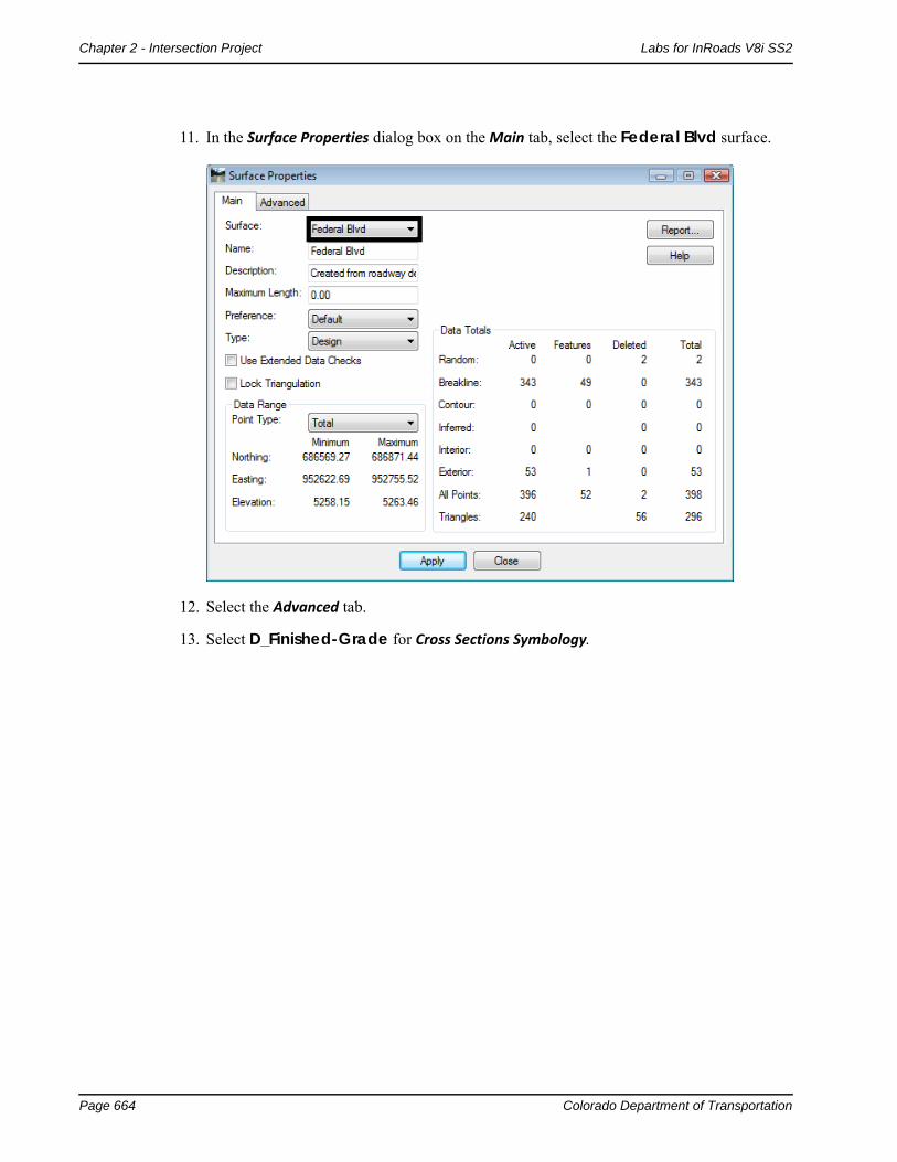
11. In the Surface Properties dialog box on the Main tab, select the Federal Blvd surface.
12. Select the Advanced tab.
13. Select D_Finished-Grade for Cross Sections Symbology.

Colorado Department of Transportation Page 665
Labs for InRoads V8i SS2 Chapter 2 - Intersection Project
14. Select D_Finished-Grade for Profile Symbology.
15. <D> Apply.
16. <D> Close.
This completes the initial design of Federal Blvd.
Create the 5th Ave Vertical AlignmentThe vertical alignment for 5th Ave. is created at this point. Using the initial Federal Blvd surface and the existing ground surface, the vertical alignment for 5th Ave. can be tied into Federal Blvd. properly.
♦ Create the crossing street profile
♦ Define the crossing street vertical alignment
Create a Profile for 5th Ave.
In order to define a vertical alignment, a profile window is required. The existing surface along with the initial Federal Blvd. surface is displayed in this profile.
1. In MicroStation, move to an area to the right of the alignments.
2. Verify the 5th_Ave horizontal alignment is active.
3. On the InRoads main menu, select Evaluation > Profile > Create Profile. This displays the Create Profile dialog box.

Page 666 Colorado Department of Transportation
Chapter 2 - Intersection Project Labs for InRoads V8i SS2
The 5x Vertical preference is used here so that the slopes are easier to see.
4. <D> Preferences and highlight the preference 5x Vertical from the list.
Note: Because there are so many settings that control the look and feel of a profile, several CDOT preferences have been created that can save the end user a significant amount of time setting up and creating a profile. Be sure to use a standard preference as much as possible.
5. <D> Load to load the preference and then <D> Close.
6. On the General leaf, enter 5th_Ave for the Set Name.
7. Toggle on Right to Left in the Direction area.
8. Toggle on the 16628_Existing and Federal Blvd surfaces.
9. <D> on the Controls leaf.
10. Toggle on Use in the Station area.
Because this lab is concerned with just the intersection, the vertical alignment (and the profile) is constructed to cover just the area of the intersection.
11. Key in 6+00.00 for the Start station.

Colorado Department of Transportation Page 667
Labs for InRoads V8i SS2 Chapter 2 - Intersection Project
12. Key in 9+98.50 for the Stop station.
13. Toggle on Apply in the Window Clearance area.
14. Key in 25 for both the Top: and Bottom.
15. <D> Apply.
16. <D> in the MicroStation view window to identify the profile’s location. Because the Direction was set to Right to Left, the profile will be place to the right of the data point.
17. The profile should look similar to the following:
18. <D> Close on the Create Profile dialog box to dismiss it.

Page 668 Colorado Department of Transportation
Chapter 2 - Intersection Project Labs for InRoads V8i SS2
Define the 5th Ave Vertical Alignment
1. Select the Geometry bottom tab from the InRoads Explorer.
2. Expand the Federal@5thAve geometry project to show the 5th_Ave horizontal alignment.
3. <R> on the 5th_Ave horizontal alignment and select New from the menu.
4. In the New dialog Box, set the Type to Vertical Alignment.
5. In the Name field, key in 5th_Ave-V.
6. In the Description field, key in 5th Ave Vertical Alignment.
7. Set the Style to ALG_PRO_Vert. (This stands for Alignment Proposed Vertical)
Colorado Department of Transportation Page 669
Labs for InRoads V8i SS2 Chapter 2 - Intersection Project
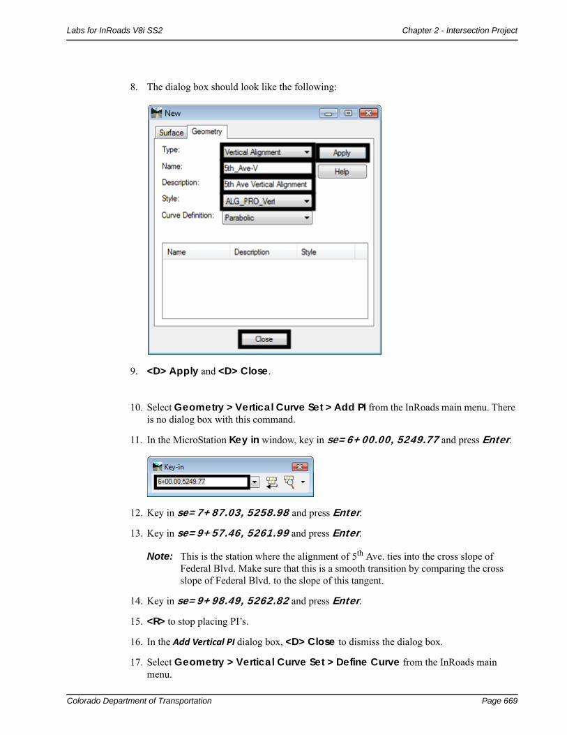
8. The dialog box should look like the following:
9. <D> Apply and <D> Close.
10. Select Geometry > Vertical Curve Set > Add PI from the InRoads main menu. There is no dialog box with this command.
11. In the MicroStation Key in window, key in se=6+00.00, 5249.77 and press Enter.
12. Key in se=7+87.03, 5258.98 and press Enter.
13. Key in se=9+57.46, 5261.99 and press Enter.
Note: This is the station where the alignment of 5th Ave. ties into the cross slope of Federal Blvd. Make sure that this is a smooth transition by comparing the cross slope of Federal Blvd. to the slope of this tangent.
14. Key in se=9+98.49, 5262.82 and press Enter.
15. <R> to stop placing PI’s.
16. In the Add Vertical PI dialog box, <D> Close to dismiss the dialog box.
17. Select Geometry > Vertical Curve Set > Define Curve from the InRoads main menu.
Page 670 Colorado Department of Transportation
Chapter 2 - Intersection Project Labs for InRoads V8i SS2
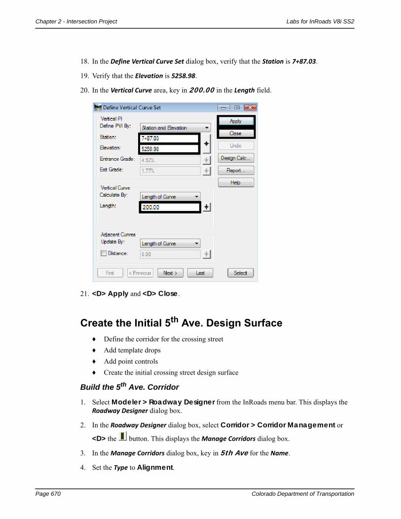
18. In the Define Vertical Curve Set dialog box, verify that the Station is 7+87.03.
19. Verify that the Elevation is 5258.98.
20. In the Vertical Curve area, key in 200.00 in the Length field.
21. <D> Apply and <D> Close.
Create the Initial 5th Ave. Design Surface♦ Define the corridor for the crossing street
♦ Add template drops
♦ Add point controls
♦ Create the initial crossing street design surface
Build the 5th Ave. Corridor
1. Select Modeler > Roadway Designer from the InRoads menu bar. This displays the Roadway Designer dialog box.
2. In the Roadway Designer dialog box, select Corridor > Corridor Management or
<D> the button. This displays the Manage Corridors dialog box.
3. In the Manage Corridors dialog box, key in 5th Ave for the Name.
4. Set the Type to Alignment.

Colorado Department of Transportation Page 671
Labs for InRoads V8i SS2 Chapter 2 - Intersection Project
5. Select 5th_Ave as the Horizontal Alignment.
6. Select 5th_Ave -V as the Vertical Alignment.
7. Toggle off Station in the Limits area.
8. <D> Add to complete the corridor.
9. <D> Close to dismiss the Manage Corridors dialog box.
Add 5th Ave. Template Drops
The pavement for 5th Ave. needs to change from an asphalt pavement to a concrete pavement as it approaches Federal Blvd. This takes place at Sta. 8+30.00. Therefore, the asphalt template is
used from the beginning of the 5th Ave. corridor to station 8+29.99. The concrete template is used from station 8+30.00 to the end of the project. Switching templates in 1/100 of a foot gives a clean change between templates.
1. In the Roadway Designer dialog box, select Corridor > Template Drops or <D> the button. This displays the Template Drops dialog box.
2. Verify the Corridor is set to 5th Ave.
3. In the Template Drops dialog box, Key in 6+00.00 for the Station.

Page 672 Colorado Department of Transportation
Chapter 2 - Intersection Project Labs for InRoads V8i SS2
4. Key in 25 for the Interval.
5. In the Library Templates area, expand the 1 – Templates folder.
6. Highlight the 5th_Ave_Asphalt template.
7. <D> Add.
8. Key in 8+29.99 for the Station.
9. Highlight the 5th_Ave_Asphalt template.
10. <D> Add.
11. Key in 8+30.00 for the Station.
12. Highlight the 5th_Ave_Concrete template.
13. <D> Add.

Colorado Department of Transportation Page 673
Labs for InRoads V8i SS2 Chapter 2 - Intersection Project
14. The template drops appear in the dialog box as shown below:
15. <D> Close.
Add 5th Ave. Point Controls
The templates are defined to be used “as is” at the beginning of the alignment and are to widen out as Federal Blvd. is approached. The point controls used here reflect the area of widening where 5th Ave. approaches Federal Blvd.
Because the asphalt template and the concrete template use different point names, point controls have to be defined for each template. This first set of point controls define the widening on the right side of 5th Ave. This widening is constant through the corridor.
1. In the Roadway Designer dialog box, select Corridor > Point Controls or <D> the button. This displays the Point Controls dialog box.
2. In the Control Description field, key in 5th Ave Rt Asph EOP Control.
3. In the Point Controls dialog box, set the Point to RT_HMA_Lift1_Laneline-Top using the
drop down menu or the Button.
4. Toggle on Horizontal in the Mode area.
5. Set the Control Type to Alignment.

Page 674 Colorado Department of Transportation
Chapter 2 - Intersection Project Labs for InRoads V8i SS2
6. Set the Horizontal Alignment to 5th_Ave.
Note: The settings made in steps 3 through 5 are used for setting up all of the point controls that follow.
7. In the Station Limits area, key in 6+00.00 for the Start station.
8. Key in 8+29.99 for the Stop station.
9. In the Horizontal Offsets area, key in 23.89 for the Start and Stop offsets.
10. <D> Add.
11. Advance the Station to 8+30.00 in the Roadway Designer plan view window.
12. In the Control Description field, key in 5th Ave Rt Conc EOP Control.
13. In the Point Controls dialog box, set the Point to RT_Conc_Laneline-Top using the
drop down menu or the button.
14. In the Station Limits area, key in 8+30.00 for the Start station.
15. Key in 9+98.50 for the Stop station.
16. In the Horizontal Offsets area, key in 23.89 for the Start and Stop offsets.
17. <D> Add.
This set of point controls define the widening on the left side of 5th Ave. It is constant from the beginning of the corridor to station 8+30.00 (where the templates change). From here it transitions out to provide the additional width for right turns. The additional width is maintained to the end of the corridor.

Colorado Department of Transportation Page 675
Labs for InRoads V8i SS2 Chapter 2 - Intersection Project
18. In the Control Description field, key in 5th Ave Lt Asph EOP Control.
19. Set the Point to LT_HMA_Lift1_Laneline-Top.
20. In the Station Limits area, key in 6+00.00 for the Start station.
21. Key in 8+29.99 for the Stop station.
22. In the Horizontal Offsets area, key in -12.45 for the Start and Stop offsets.
23. <D> Add.
The next series of steps define the tapered area of the widening.
24. In the Control Description field, key in 5th Ave Lt Conc EOP Transition Control.
25. Set the Point to LT_Conc_Laneline-Top.
26. In the Station Limits area, key in 8+30.00 for the Start station.
27. Key in 9+00.48 for the Stop station.
28. In the Horizontal Offsets area, key in -12.45 for the Start offset.
29. Key in -15.87 for the Stop offset.
30. <D> Add.
For the final point control use the following steps:
31. In the Control Description field, key in 5th Ave Lt Conc EOP Full Width Control.
32. In the Station Limits area, key in 9+00.48 for the Start station.
33. Key in 9+98.50 for the Stop station.
34. In the Horizontal Offsets area, key in -15.87 for the Start and Stop offsets.
35. <D> Add.
Page 676 Colorado Department of Transportation
Chapter 2 - Intersection Project Labs for InRoads V8i SS2
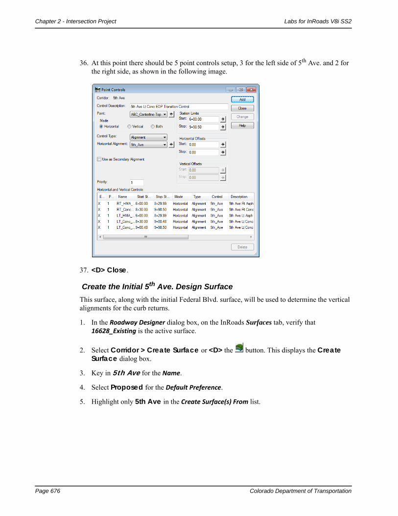
36. At this point there should be 5 point controls setup, 3 for the left side of 5th Ave. and 2 for the right side, as shown in the following image.
37. <D> Close.
Create the Initial 5th Ave. Design Surface
This surface, along with the initial Federal Blvd. surface, will be used to determine the vertical alignments for the curb returns.
1. In the Roadway Designer dialog box, on the InRoads Surfaces tab, verify that 16628_Existing is the active surface.
2. Select Corridor > Create Surface or <D> the button. This displays the Create Surface dialog box.
3. Key in 5th Ave for the Name.
4. Select Proposed for the Default Preference.
5. Highlight only 5th Ave in the Create Surface(s) From list.

Colorado Department of Transportation Page 677
Labs for InRoads V8i SS2 Chapter 2 - Intersection Project
6. The remaining settings should be correct. If not, set them to match the illustration below.
7. <D> Apply.
8. <D> Close.
9. Select File > Save from the Roadway Designer menu bar.
10. Close the Roadway Designer dialog box.
11. From the InRoads menu bar, select Surface > Surface Properties. This displays the Surface Properties dialog box.
12. In the Surface Properties dialog box on the Main tab, select the 5th Ave surface.
13. Select the Advanced tab.
14. Select D_Finished-Grade for Cross Sections Symbology.
15. Select D_Finished-Grade for Profile Symbology.
16. <D> Apply and <D> Close.
Section Summary:
At this point there are two initial design surfaces created; a mainline and the crossing street. In order for these surfaces to match up through the intersection additional, geometry will need to be created.

Page 678 Colorado Department of Transportation
Chapter 2 - Intersection Project Labs for InRoads V8i SS2
Additional GeometrySection Objectives:
Create horizontal and vertical geometry for curb returns
In this section the two initial design surfaces are used to create smooth vertical alignment transitions around the corners of the intersection. Horizontal and vertical geometry for each curb return is defined with the InRoads Create Multicenter Curves tool. The new geometry will be used to create the final design surface.
Curb ReturnsBecause this example is a T-intersection there are only two curb returns to model. In a typical intersection there are four returns to model. The steps shown below can also be used to develop curb returns for an intersection with more than one crossing street.
Create Northeast Curb Return
1. From the InRoads menu bar, select Geometry > Utilities > Multicenter Curve… This displays the Multicenter Curve dialog box.
2. On the Main tab of the Multicenter Curve dialog box, set the Curve Type to One Center.
3. In the Radii area, key in 75 for Radius 1.
4. In the Widths area, key in 23.89 for Width 1. This is the width of 5th Ave. from its centerline to the right edge of pavement.

Colorado Department of Transportation Page 679
Labs for InRoads V8i SS2 Chapter 2 - Intersection Project
5. Key in 41 for Width 2. This is the width of Federal Blvd. from its centerline to the right edge of pavement.
Important! Use the graphic in the Example area to determine how to enter your curb data. This graphic changes according to the Curve Type:. As an example, when prompted by the software to choose the first alignment, choose the alignment that is associated with Width 1.
6. <D> the Advanced tab.
The steps below define the properties of the horizontal alignment representing the northeast curb return.
7. In the Name field of the Alignment area, key in 5th_Ave_NE-Quadrant.
8. In the Description field, key in NE Return for Federal & 5th.
9. Set the Style to ALG_OTHER.
The following steps define the vertical alignment for the curb return. Because the 5th Ave. width was entered in Width 1 previously, 5th Ave. data must be used in the First Selected Alignment fields here. The Federal Blvd. data is used in the Second Selected Alignment fields.

Page 680 Colorado Department of Transportation
Chapter 2 - Intersection Project Labs for InRoads V8i SS2
10. Toggle on Create Vertical Alignment.
11. In the First Selected Alignment area, toggle on Surface.
12. Select 5th Ave for the surface.
13. In the Second Selected Alignment area, toggle on Surface.
14. Select Federal Blvd for the surface.
The dialog box should now look like the image below.
15. <D> Apply.
Important! Now you must select the alignments in the same order that they were defined in the dialog box.
The following message is displayed in the lower left corner of the MicroStation window:

Colorado Department of Transportation Page 681
Labs for InRoads V8i SS2 Chapter 2 - Intersection Project
16. <D> on the 5th_Ave alignment in the MicroStation view window. The following message is displayed:
17. <D> on the Federal CL alignment. The following message is displayed:
18. <D> above the 5th_Ave alignment and to the right of the Federal CL alignment. The curb return alignment is displayed.
19. <D> one more time to Accept the creation of the new alignment.
Create Southeast Curb Return
Again, the 5th Ave. data is used first to create the southeast curb return.
1. From the InRoads menu bar, select Geometry > Utilities > Multicenter Curve…
2. On the Main tab, in the Radii area, key in 60 for Radius 1.
3. In the Widths area, key in 15.87 for Width 1.
Page 682 Colorado Department of Transportation
Chapter 2 - Intersection Project Labs for InRoads V8i SS2
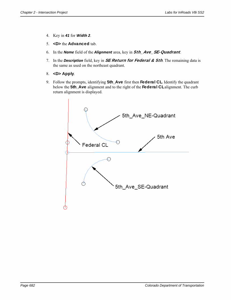
4. Key in 41 for Width 2.
5. <D> the Advanced tab.
6. In the Name field of the Alignment area, key in 5th_Ave_SE-Quadrant.
7. In the Description field, key in SE Return for Federal & 5th. The remaining data is the same as used on the northeast quadrant.
8. <D> Apply.
9. Follow the prompts, identifying 5th_Ave first then Federal CL. Identify the quadrant below the 5th_Ave alignment and to the right of the Federal CL alignment. The curb return alignment is displayed.

Colorado Department of Transportation Page 683
Labs for InRoads V8i SS2 Chapter 2 - Intersection Project
10. Verify that the new alignments show up in the Geometry tab of InRoads Explorer as shown below.
Section Summary:
The Multicenter Curve tool created smooth horizontal and vertical alignments from the surface of the cross street to the surface of the mainline. You may need to modify these alignments depending on the actual design needs for the flowline.
Final Design ModelingSection Objectives:
Revise the point controls and template drops for 5th Ave using new curb return alignments.
Use Target Aliasing to match the surface of Federal Blvd to the surface of 5th Ave.
Update the 5th Ave surface
Update Federal Blvd. template drops and add point controls
Create a complete final combined surface
Create the Final 5th Ave. Corridor SurfaceThe 5th Ave. design surface is created first so that a feature in that surface can be used to control
the edge of Federal Blvd. through the intersection. The 5th Ave. corridor is used to clip the Federal Blvd. corridor, removing the curb and gutter through the intersection that would normally be placed by the Federal Blvd. template.

Page 684 Colorado Department of Transportation
Chapter 2 - Intersection Project Labs for InRoads V8i SS2
Edit 5th Ave. Corridor Definition
The 5th Ave corridor is going to clip out portions of the Federal Blvd. corridor when the final surface is created. If the 5th Ave. corridor clips any of the driving lane components in the Federal Blvd. template, those components will be lost for calculating volumes. In order to prevent this from occurring, The corridor for 5th Ave. is stopped before it reaches the edge of the Federal Blvd. template.
1. Select Modeler > Roadway Designer from the InROads main menu.
2. In the Roadway Designer dialog box, select Corridor > Corridor Management or
<D> the button. This displays the Manage Corridors dialog box.
3. Highlight 5th Ave in the Corridors list.
4. Toggle on Station in the Limits area.
5. Key in 9+40.00 for the Stop station. This station was selected because it is about halfway through the curb returns and before the edge of Federal Blvd.
6. <D> Change.
7. <D> Close.
Edit 5th Ave. Template Drops
1. In the Roadway Designer dialog box, select Corridor > Template Drops or <D> the button. This displays the Template Drops dialog box.
2. Verify that the Corridor is set to 5th Ave.
3. In the Template Drops dialog box, Key in 8+80.00 for the Station.

Colorado Department of Transportation Page 685
Labs for InRoads V8i SS2 Chapter 2 - Intersection Project
4. Key in 1 for the Interval
Note: An interval of 1 is used here in order to sufficiently model the surface around the curb returns.
5. In the Library Templates area, expand the 1 – Templates folder.
6. Highlight the 5th_Ave_Concrete template.
7. <D> Add.
8. <D> Close.
5th Ave. Point Controls for Curb Returns
Additional point controls are added to the 5th Ave. corridor to use the curb return alignments. The existing point controls for the concrete pavement must also be modified so that they do not overlap the curb returns.
1. In the Roadway Designer dialog box, select Corridor > Point Controls or <D> the button.
2. In the Control Description field, key in 5th Ave Rt Conc EOP Return Control.
3. Set the Point to RT_Conc_Laneline-Top using the drop down menu or the button.

Page 686 Colorado Department of Transportation
Chapter 2 - Intersection Project Labs for InRoads V8i SS2
4. Toggle on Both in the Mode area.
5. Set the Control Type to Alignment.
6. Set the Horizontal Alignment to 5th_Ave_NE-Quadrant.
Note: Selecting the 5th_Ave_NE-Quadrant alignment automatically sets the Station Limits to cover that alignment.
7. Toggle on Use as Secondary Alignment.
8. <D> Add.
Important! The entry is displayed in orange, indicating that there is a conflict with another point control. The point control entered during the initial modeling is now too long, so its end station must be adjusted.
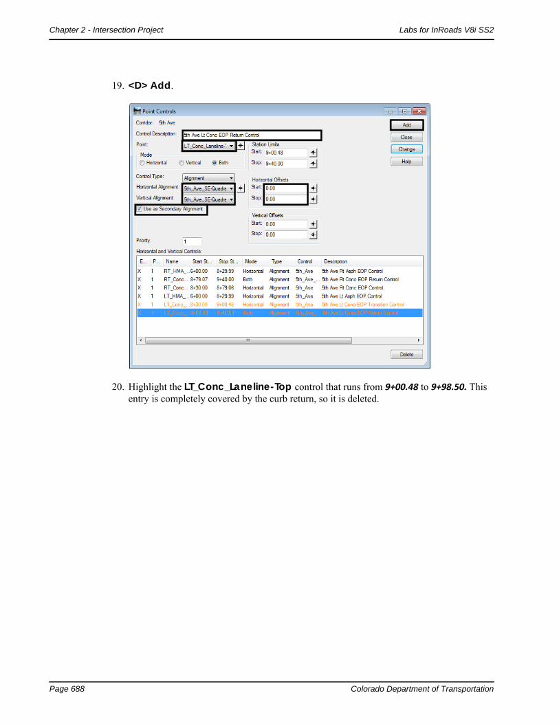
9. Highlight the RT_Conc_Laneline-Top control that runs from 8+30.00 to 9+98.50.
10. In the Station Limits area, key in 8+79.06 for the Stop station. This stops the point control where the curb return control starts.

Colorado Department of Transportation Page 687
Labs for InRoads V8i SS2 Chapter 2 - Intersection Project
11. <D> Change.
12. In the Control Description field, key in 5th Ave Rt Conc EOP Return Control.
13. Set the Point to LT_Conc_Laneline-Top using the drop down menu or the button.
14. Toggle on Both in the Mode area.
15. Set the Control Type to Alignment.
16. Set the Horizontal Alignment to 5th_Ave_SE-Quadrant.
17. Toggle on Use as Secondary Alignment. This is so that the curb component is placed perpendicular to the curb return alignment.
18. In the Horizontal Offsets area, key in 0 for the Start and Stop offsets.
Page 688 Colorado Department of Transportation
Chapter 2 - Intersection Project Labs for InRoads V8i SS2
19. <D> Add.
20. Highlight the LT_Conc_Laneline-Top control that runs from 9+00.48 to 9+98.50. This entry is completely covered by the curb return, so it is deleted.

Colorado Department of Transportation Page 689
Labs for InRoads V8i SS2 Chapter 2 - Intersection Project
21. <D> Delete.
The illustration below shows the list of point controls used on the Final 5th Ave. corridor.
Page 690 Colorado Department of Transportation
Chapter 2 - Intersection Project Labs for InRoads V8i SS2
22. Close the Point Control dialog box.
23. Select File > Save from the Roadway Designer menu bar.998
Create the Final 5th Ave. Design Surface
The 5th Ave. surface is remodeled to incorporate the corridor changes made above and to generate the feature that will control the edge of pavement for Federal Blvd.
The target aliasing is set up so that the 5th Ave corridor will clip the Federal Blvd. corridor when the final surface is created.
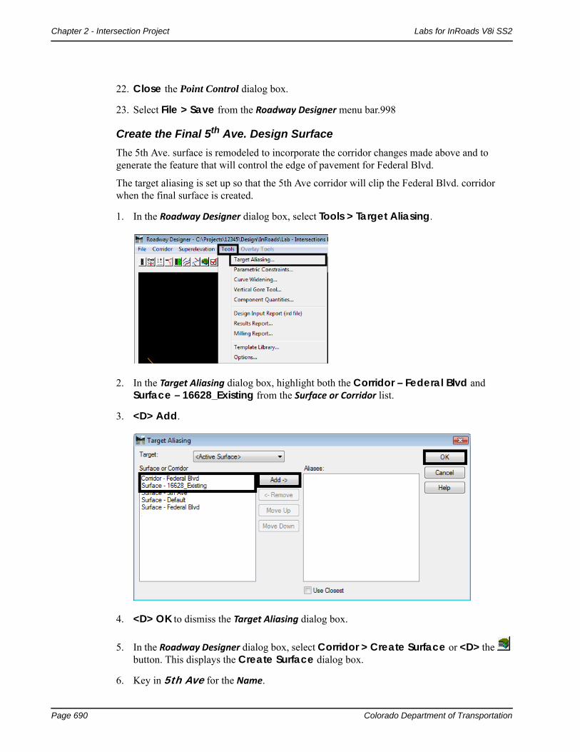
1. In the Roadway Designer dialog box, select Tools > Target Aliasing.
2. In the Target Aliasing dialog box, highlight both the Corridor – Federal Blvd and Surface – 16628_Existing from the Surface or Corridor list.
3. <D> Add.
4. <D> OK to dismiss the Target Aliasing dialog box.
5. In the Roadway Designer dialog box, select Corridor > Create Surface or <D> the button. This displays the Create Surface dialog box.
6. Key in 5th Ave for the Name.

Colorado Department of Transportation Page 691
Labs for InRoads V8i SS2 Chapter 2 - Intersection Project
7. Select Proposed for the Default Preference.
8. Highlight only 5th Ave in the Create Surface(s) From list.
Transverse features run perpendicular to the corridor alignment and are placed at each template drop. The last transverse feature created on the 5th Ave. corridor will be used to control the edge of Federal Blvd. through the intersection.
9. Toggle on Add Transverse Features.
10. Set the transverse feature Style to DTM_Transverse.
11. Toggle on Display Features in Plan View. (These features will be used to identify important stationing for Federal Blvd. template drops.
12. <D> Apply and <D> Close.
13. If necessary, click Fit View to see the new graphics.
Final Federal Blvd. Corridor SurfaceAdditional template drops and point controls are required on Federal Blvd. as well. The template drops change the interval to model smoothly around the curb returns. The point controls are used to model the remaining parts of the curb returns and the intersection driving surface.

Page 692 Colorado Department of Transportation
Chapter 2 - Intersection Project Labs for InRoads V8i SS2
Section Objectives:
♦ Add template drops to tie into 5th Ave corridor
♦ Add point controls
Collect Station Information for Template Drops
The locations for the template drops and point controls are determined using tracking.
1. In the InRoads main dialog box, set the InRoads Explorer to the Geometry tab.
2. Set the Federal CL as the active alignment.
3. <R> on the Federal@5thAve geometry project and select View All Horizontals from the menu.
4. In the MicroStation view window, zoom in around the intersection.
5. Select Tools > Tracking > Tracking from the InRoads menu bar.
6. In the Tracking dialog box, <D> the Activate button.
7. <T> to each of the points indicated in the illustration below and write down the Station for each.

Colorado Department of Transportation Page 693
Labs for InRoads V8i SS2 Chapter 2 - Intersection Project
These stations are (from bottom to top):
♦ 0+57.22
♦ 1+00.73
♦ 1+86.15
♦ 2+30.80
Template drops are required at the first an last stations. The first station starts the one foot intervals around the SE curb return. The last station is at the end of the intersection and goes back to a 25 foot interval.
8. In the Roadway Designer dialog box, select Corridor > Template Drops or <D> the button. This displays the Template Drops dialog box.
9. Verify the Corridor is set to Federal Blvd.
10. In the Template Drops dialog box, key in 0+57.22 for the Station.
11. Key in 1 for the Interval.
12. Highlight Federal Blvd in the Library Templates list.
13. <D> Add.
14. Key in 2+30.80 for the Station.
15. Key in 25 for the Interval.

Page 694 Colorado Department of Transportation
Chapter 2 - Intersection Project Labs for InRoads V8i SS2
16. <D> Add. The list of template drops is illustrated below.
17. <D> Close.
Federal Blvd. Point Controls for Curb Returns
All four of the stations located above are used for point controls. The first and second stations create a control for the SE curb return. The second and third stations create a point control that follows the last transverse feature in the 5th Ave. surface. The third and fourth stations create a control for the NE curb return.
1. In the Roadway Designer dialog box, select Corridor > Point Controls or <D> the button.
2. In the Control Description field, key in Federal EOP SE Quad Return Control.
3. Set the Point to RT_Conc_Laneline-Top6 using the drop down menu or the button.
4. Toggle on Both in the Mode area.
5. Set the Control Type to Alignment.
6. Set the Horizontal Alignment to 5th_Ave_SE-Quadrant.
7. Toggle on Use as Secondary Alignment.
Colorado Department of Transportation Page 695
Labs for InRoads V8i SS2 Chapter 2 - Intersection Project
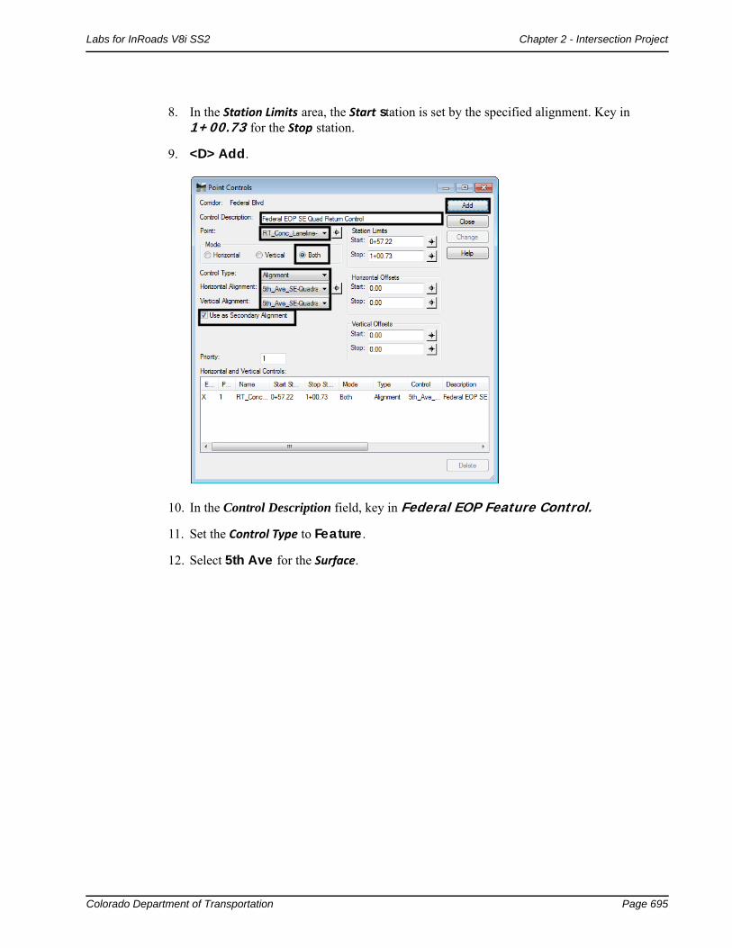
8. In the Station Limits area, the Start station is set by the specified alignment. Key in 1+00.73 for the Stop station.
9. <D> Add.
10. In the Control Description field, key in Federal EOP Feature Control.
11. Set the Control Type to Feature.
12. Select 5th Ave for the Surface.

Page 696 Colorado Department of Transportation
Chapter 2 - Intersection Project Labs for InRoads V8i SS2
13. Select 9+40.00 for the Feature.
14. In the Station Limits area, key in 1+00.73 for the Start station.
15. Key in 1+86.15 for the Stop station.

Colorado Department of Transportation Page 697
Labs for InRoads V8i SS2 Chapter 2 - Intersection Project
16. <D> Add.
17. In the Control Description field, key in Federal EOP NE Quad Control.
18. Set the Control Type to Alignment.
19. Set the Horizontal Alignment to 5th_Ave_NE-Quadrant.18In the Station Limits area, key in 1+86.15 for the Start station. The Stop station is set by the selected alignment.

Page 698 Colorado Department of Transportation
Chapter 2 - Intersection Project Labs for InRoads V8i SS2
20. <D> Add. and <D> Close.
Create the Final Intersection Design Surface
After creating the point controls for Federal Blvd. (using features from the 5th Ave. design surface), both corridors are used to create the design surface of the entire intersection.
1. Verify that 16628_Existing is the active surface.
Note: If the Existing surface is not the active surface several template drop errors will be listed in the Results dialog box indicating problems with the final surface.
2. In the Roadway Designer dialog box, select Corridor > Create Surface or <D> the button. This displays the Create Surface dialog box.
3. Key in Federal and 5th Intersection for the Name.
4. Select Proposed for the Default Preference.
5. Highlight both 5th Ave and Federal Blvd in the Create Surface(s) From: list.
6. <D> the Clipping Options button.
7. Verify that the Clipping Option is set to Clip All.
8. <D> OK on the Clipping Options dialog box.
9. Toggle on Add Transverse Features.
10. Set the transverse feature Style to DTM_Transverse.

Colorado Department of Transportation Page 699
Labs for InRoads V8i SS2 Chapter 2 - Intersection Project
11. Toggle on Display Features in Plan View. This displays the surface features in the dgn file for review.
12. <D> Apply and <D> Close.
13. Select File > Save from the Roadway Designer menu bar.
14. <D> Close to dismiss the Roadway Designer dialog box.

Page 700 Colorado Department of Transportation
Chapter 2 - Intersection Project Labs for InRoads V8i SS2
15. Examine the features displayed in the MicroStation view window. The illustrations below show the finished intersection.
16. Use the rotate view command to see the features in 3D

![A Practical Guide for Using MicroStation V8i SS2[1]](https://static.fdocuments.in/doc/165x107/55cf98d0550346d03399d256/a-practical-guide-for-using-microstation-v8i-ss21.jpg)