L-861T LED ELEVATED TAXIWAY EDGE LIGHT
32
Y3-01-0149 Rev (F) April 18, 2013 INSTALLATION AND MAINTENANCE MANUAL L-861T LED ELEVATED TAXIWAY EDGE LIGHT PN 861T-L-B-066-XX-X Lot # 5408-74 and higher ASTRONICS DME CORPORATION 6830 N.W. 16 th TERRACE FT. LAUDERDALE, FLORIDA 33309
Transcript of L-861T LED ELEVATED TAXIWAY EDGE LIGHT
Y3-01-0149 Rev (F)
April 18, 2013
INSTALLATION AND MAINTENANCE MANUAL
L-861T LED ELEVATED TAXIWAY
EDGE LIGHT
PN 861T-L-B-066-XX-X
Lot # 5408-74 and higher
ASTRONICS DME CORPORATION
6830 N.W. 16th TERRACE FT. LAUDERDALE, FLORIDA 33309

Y3-01-0149 Rev (F)
ii
April 18, 2013
This page intentionally left blank.

Y3-01-0149 Rev (F)
iii
April 18, 2013
RECORD OF CHANGES
Version Number Date Description
(-) 8-23-07 ECO #16511 Original Issue
(A) 7-1-08 ECO #17155
(B) 3-23-09 ECO #17720
(C) 7-28-09 ECO #18015
(D) 9-30-10 ECO #18756
(E) 11-21-12 ECO #19893
(F) 4-18-13 ECO #20087

Y3-01-0149 Rev (F)
iv
April 18, 2013
This page intentionally left blank.

Y3-01-0149 Rev (F)
v
April 18, 2013
LIST OF EFFECTIVE PAGES
Page Number Issue Page Number Issue
Title April 18, 2013
ii thru vi April 18, 2013
1-1 thru 1-6 April 18, 2013
2-1 thru 2-2 April 18, 2013
3-1 thru 3-2 April 18, 2013
4-1 thru 4-4 April 18, 2013
5-1 thru 5-2 April 18, 2013
6-1 thru 6-4 April 18, 2013
7-1 thru 7-4 April 18, 2013

Y3-01-0149 Rev (F)
vi
April 18, 2013
This page intentionally left blank.
Y3-01-0149 Rev (F)
vii
April 18, 2013
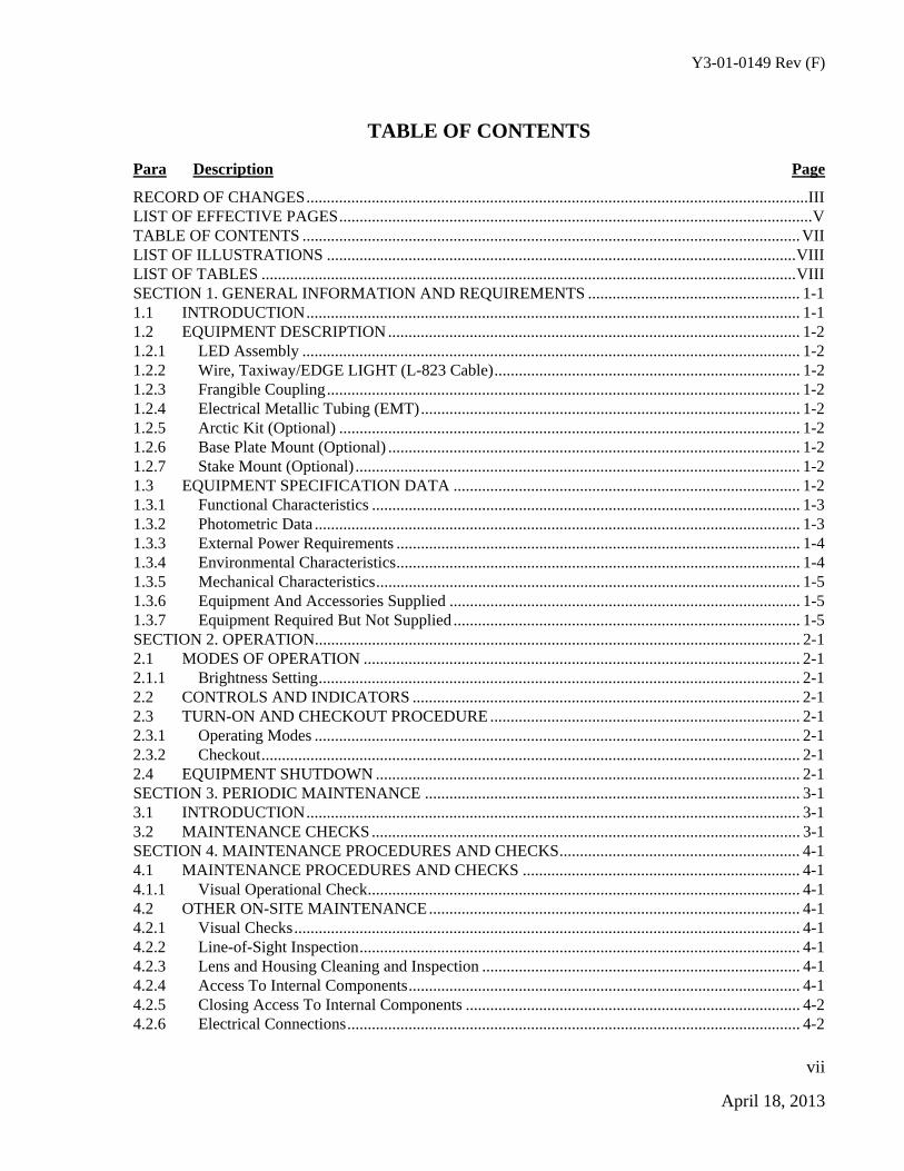
TABLE OF CONTENTS
Para Description Page
RECORD OF CHANGES ........................................................................................................................... III LIST OF EFFECTIVE PAGES .................................................................................................................... V TABLE OF CONTENTS .......................................................................................................................... VII LIST OF ILLUSTRATIONS ................................................................................................................... VIII LIST OF TABLES ................................................................................................................................... VIII SECTION 1. GENERAL INFORMATION AND REQUIREMENTS .................................................... 1-1 1.1 INTRODUCTION ......................................................................................................................... 1-1 1.2 EQUIPMENT DESCRIPTION ..................................................................................................... 1-2 1.2.1 LED Assembly .......................................................................................................................... 1-2 1.2.2 Wire, Taxiway/EDGE LIGHT (L-823 Cable) ........................................................................... 1-2 1.2.3 Frangible Coupling .................................................................................................................... 1-2 1.2.4 Electrical Metallic Tubing (EMT) ............................................................................................. 1-2 1.2.5 Arctic Kit (Optional) ................................................................................................................. 1-2 1.2.6 Base Plate Mount (Optional) ..................................................................................................... 1-2 1.2.7 Stake Mount (Optional) ............................................................................................................. 1-2 1.3 EQUIPMENT SPECIFICATION DATA ..................................................................................... 1-2 1.3.1 Functional Characteristics ......................................................................................................... 1-3 1.3.2 Photometric Data ....................................................................................................................... 1-3 1.3.3 External Power Requirements ................................................................................................... 1-4 1.3.4 Environmental Characteristics ................................................................................................... 1-4 1.3.5 Mechanical Characteristics ........................................................................................................ 1-5 1.3.6 Equipment And Accessories Supplied ...................................................................................... 1-5 1.3.7 Equipment Required But Not Supplied ..................................................................................... 1-5 SECTION 2. OPERATION ....................................................................................................................... 2-1 2.1 MODES OF OPERATION ........................................................................................................... 2-1 2.1.1 Brightness Setting ...................................................................................................................... 2-1 2.2 CONTROLS AND INDICATORS ............................................................................................... 2-1 2.3 TURN-ON AND CHECKOUT PROCEDURE ............................................................................ 2-1 2.3.1 Operating Modes ....................................................................................................................... 2-1 2.3.2 Checkout .................................................................................................................................... 2-1 2.4 EQUIPMENT SHUTDOWN ........................................................................................................ 2-1 SECTION 3. PERIODIC MAINTENANCE ............................................................................................ 3-1 3.1 INTRODUCTION ......................................................................................................................... 3-1 3.2 MAINTENANCE CHECKS ......................................................................................................... 3-1 SECTION 4. MAINTENANCE PROCEDURES AND CHECKS ........................................................... 4-1 4.1 MAINTENANCE PROCEDURES AND CHECKS .................................................................... 4-1 4.1.1 Visual Operational Check .......................................................................................................... 4-1 4.2 OTHER ON-SITE MAINTENANCE ........................................................................................... 4-1 4.2.1 Visual Checks ............................................................................................................................ 4-1 4.2.2 Line-of-Sight Inspection ............................................................................................................ 4-1 4.2.3 Lens and Housing Cleaning and Inspection .............................................................................. 4-1 4.2.4 Access To Internal Components ................................................................................................ 4-1 4.2.5 Closing Access To Internal Components .................................................................................. 4-2 4.2.6 Electrical Connections ............................................................................................................... 4-2
Y3-01-0149 Rev (F)
viii
April 18, 2013
4.2.7 Electrical Component Inspection ............................................................................................... 4-2 4.2.8 LED Head Assembly Removal .................................................................................................. 4-3 4.2.9 LED Head Assembly Installation .............................................................................................. 4-3 SECTION 5. CORRECTIVE MAINTENANCE ...................................................................................... 5-1 5.1 CORRECTIVE MAINTENANCE ................................................................................................ 5-1 5.1.1 Introduction ............................................................................................................................... 5-1 5.1.2 Test Equipment Required .......................................................................................................... 5-1 5.1.3 Troubleshooting Procedures ...................................................................................................... 5-1 SECTION 6. PARTS LIST ....................................................................................................................... 6-1 6.1 GENERAL .................................................................................................................................... 6-1 6.1.1 Name of Part and Description ................................................................................................... 6-1 6.1.2 Part Number ............................................................................................................................... 6-1 6.1.3 Ordering Information ................................................................................................................. 6-1 SECTION 7. INSTALLATION ................................................................................................................ 7-1 7.1 INTRODUCTION ......................................................................................................................... 7-1 7.2 UNPACKING ................................................................................................................................ 7-1 7.3 PLACEMENT ............................................................................................................................... 7-1 7.4 INSTALLATION .......................................................................................................................... 7-1 7.4.1 Base Mounting ........................................................................................................................... 7-1 7.4.2 Light Base Mounting ................................................................................................................. 7-1 7.4.3 Light Fixture Leveling ............................................................................................................... 7-3 7.4.4 Stake Mounting (Optional) ........................................................................................................ 7-3
LIST OF ILLUSTRATIONS
Figure Title Page
Figure 1-1 L-861 Elevated Taxiway Edge LED Light .............................................................................. 1-1 Figure 6-1 L-861T Elevated Taxiway Edge LED light ............................................................................. 6-2
LIST OF TABLES
Table Title Page
Table 1-1 Functional Characteristics ......................................................................................................... 1-3 Table 1-2 Photometric Data ....................................................................................................................... 1-3 Table 1-3 Three (3) Step Constant Current Regulator (CCR) ................................................................... 1-4 Table 1-4 External Power Requirements ................................................................................................... 1-4 Table 1-5 Environmental Characteristics .................................................................................................. 1-4 Table 1-6 Mechanical Characteristics ....................................................................................................... 1-5 Table 1-7 Equipment and Accessories Supplied ....................................................................................... 1-5 Table 1-8 Equipment and Accessories Required Not Supplied ................................................................. 1-5 Table 1-9 Isolation Transformers Not Supplied ........................................................................................ 1-6 Table 3-1 Maintenance Checks ................................................................................................................. 3-1 Table 5-1 Troubleshooting Procedures ...................................................................................................... 5-1 Table 6-1 Parts List ................................................................................................................................... 6-3

Y3-01-0149 Rev (F)
1-1
April 18, 2013
SECTION 1. GENERAL INFORMATION AND REQUIREMENTS
1.1 INTRODUCTION
This manual is applicable to L-861T Fixtures Lot # 5408-77 and higher only. Refer to DME Document #Y3-01-0158 Addendum to L-861T Elevated Taxiway Edge LED Light Installation and Maintenance Manual for additional information on L-861T Fixtures Lot # 5408-76 and below.
This section describes the DME Corporation L-861T Elevated Taxiway Edge Light Emitting Diode (LED) light.
The L-861T Elevated Taxiway Edge LED light is used to delineate the edges of airport taxiways, holding bays, and aprons. These elevated lights, Part Numbers (PN) 861T-L-B-066-XX-0, 861T-L-B-066-XX-1, 861T-L-B-066-XX-2, and 861T-L-B-066-XX-3 are Electrical Testing Labs (ETL) certified according to FAA specification AC 150/5345-46C, and FAA LED specifications and PNs 861T-L-B-066-XX-4, 861T-L-B-066-XX-5, 861T-L-B-066-XX-6, and 861T-L-B-066-XX-7 are certified according to FAA specification AC 150/5345-46D and FAA LED specifications. The DME Corporation L-861T fixture is available in aviation blue.
LED ASSEMBLY
FRANGIBLE COUPLING AND L-823 CABLE
L-867 BASE PLATE (Not Supplied)
EMT
CLAMP
Figure 1-1 L-861 Elevated Taxiway Edge LED Light

Y3-01-0149 Rev (F)
1-2
April 18, 2013
1.2 EQUIPMENT DESCRIPTION
The main items in the L-861T Elevated Taxiway Edge LED light are listed below and shown in Figure 1-1.
1.2.1 LED ASSEMBLY
The major components of the LED Assembly consists of the LED housing assembly, LED head assembly, clamp, frangible coupling, cable assembly, and aviation blue lens shown in Figure 1-1.
1.2.2 WIRE, TAXIWAY/EDGE LIGHT (L-823 CABLE)
The wire consists of an L823 cable, the strain relief and fast receptacle connectors are then attached to the cable.
1.2.3 FRANGIBLE COUPLING
The frangible coupling is used to connect the EMT to the base plate.
1.2.4 ELECTRICAL METALLIC TUBING (EMT)
The EMT is used to connect the LED Assembly to the frangible coupling. The cable assembly runs through the EMT and connects to the power source. The EMT comes in various sizes to provide an overall height from 14 inches to 30 inches in 2-inch increments. The measurements for the various sizes are taken from the grade to the top of the fixture.
1.2.5 ARCTIC KIT (OPTIONAL)
The Arctic Kit is an optional kit to melt ice and snow that may have collected on the lens. See Figure 6-1.
1.2.6 BASE PLATE MOUNT (OPTIONAL)
The L-861T LED Taxiway light is typically installed on the L-867 base plate. Base mounting is recommended because maintenance is easier to perform. Optional mounting can be on stake mounted 30 inch galvanized steel stake.
1.2.7 STAKE MOUNT (OPTIONAL)
Optional stake mounting of the L-861T Elevated Taxiway Edge LED light is detailed in paragraph 7.4.4. Stake-mounted lights require transformer, cables, and connectors that are designed for direct earth burial.
1.3 EQUIPMENT SPECIFICATION DATA
Table 1-1 through Table 1-8 illustrate pertinent reference data on the L-861T Elevated Taxiway Edge LED light. Included are tables containing functional characteristics, external power requirements, environmental characteristics, equipment and accessories supplied, and equipment required for operation and maintenance, but not supplied by DME Corporation.
Y3-01-0149 Rev (F)
1-3
April 18, 2013
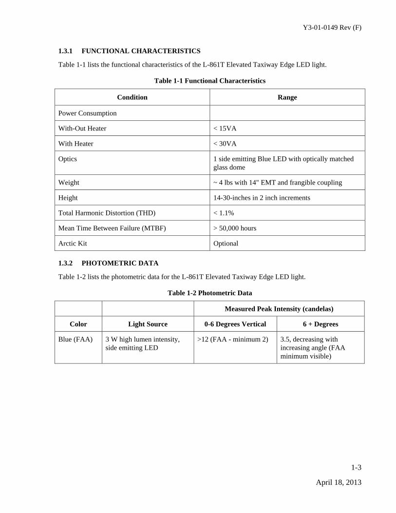
1.3.1 FUNCTIONAL CHARACTERISTICS
Table 1-1 lists the functional characteristics of the L-861T Elevated Taxiway Edge LED light.
Table 1-1 Functional Characteristics
Condition Range
Power Consumption
With-Out Heater < 15VA
With Heater < 30VA
Optics 1 side emitting Blue LED with optically matched glass dome
Weight ~ 4 lbs with 14" EMT and frangible coupling
Height 14-30-inches in 2 inch increments
Total Harmonic Distortion (THD) < 1.1%
Mean Time Between Failure (MTBF) > 50,000 hours
Arctic Kit Optional
1.3.2 PHOTOMETRIC DATA
Table 1-2 lists the photometric data for the L-861T Elevated Taxiway Edge LED light.
Table 1-2 Photometric Data
Measured Peak Intensity (candelas)
Color Light Source 0-6 Degrees Vertical 6 + Degrees
Blue (FAA) 3 W high lumen intensity, side emitting LED
>12 (FAA - minimum 2) 3.5, decreasing with increasing angle (FAA minimum visible)
Y3-01-0149 Rev (F)
1-4
April 18, 2013
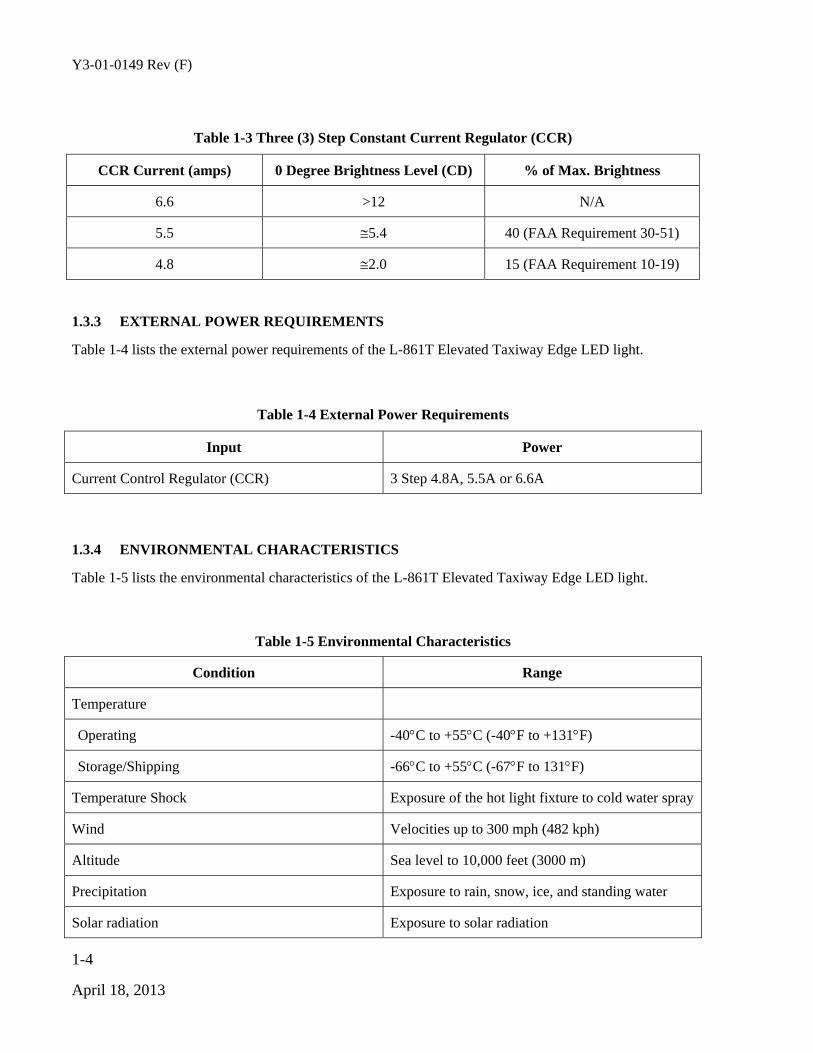
Table 1-3 Three (3) Step Constant Current Regulator (CCR)
CCR Current (amps) 0 Degree Brightness Level (CD) % of Max. Brightness
6.6 >12 N/A
5.5 5.4 40 (FAA Requirement 30-51)
4.8 2.0 15 (FAA Requirement 10-19)
1.3.3 EXTERNAL POWER REQUIREMENTS
Table 1-4 lists the external power requirements of the L-861T Elevated Taxiway Edge LED light.
Table 1-4 External Power Requirements
Input Power
Current Control Regulator (CCR) 3 Step 4.8A, 5.5A or 6.6A
1.3.4 ENVIRONMENTAL CHARACTERISTICS
Table 1-5 lists the environmental characteristics of the L-861T Elevated Taxiway Edge LED light.
Table 1-5 Environmental Characteristics
Condition Range
Temperature
Operating -40C to +55C (-40F to +131F)
Storage/Shipping -66C to +55C (-67F to 131F)
Temperature Shock Exposure of the hot light fixture to cold water spray
Wind Velocities up to 300 mph (482 kph)
Altitude Sea level to 10,000 feet (3000 m)
Precipitation Exposure to rain, snow, ice, and standing water
Solar radiation Exposure to solar radiation

Y3-01-0149 Rev (F)
1-5
April 18, 2013
1.3.5 MECHANICAL CHARACTERISTICS
Table 1-6 lists the mechanical characteristics of the L-861T Elevated Taxiway Edge LED light.
Table 1-6 Mechanical Characteristics
Condition Range
Yield Device The L-861 has a yield point near the point or position where the light attaches to the base plate. The yield point is 1-1/2 inches (38.10 mm) above grade, and will give way before any other part of the fixture is damaged, and will withstand a bending moment of 150 foot-pounds (203 Newton-meters (N-m)) without failure.
Insulation Resistance Resistance of 50 meg-ohms lead-to-case
1.3.6 EQUIPMENT AND ACCESSORIES SUPPLIED
Table 1-7 lists the equipment and accessories supplied for the L-861T Elevated Taxiway Edge LED light.
Table 1-7 Equipment and Accessories Supplied
Description Quantity
Elevated light fixture (with optical lens, clamp, EMT, frangible coupling, and LED head assembly)
1
Installation and Maintenance Manual 1 (with each order)
1.3.7 EQUIPMENT REQUIRED BUT NOT SUPPLIED
Table 1-8 and Table 1-9 list the equipment and accessories supplied for the L-861T Elevated Taxiway Edge LED light.
Table 1-8 Equipment and Accessories Required Not Supplied
Description Quantity
Cross point screwdriver 1
Isolation transformer for series circuit 1

Y3-01-0149 Rev (F)
1-6
April 18, 2013
Table 1-9 Isolation Transformers Not Supplied
Circuit Transformer Arctic Kit Installed
6.6 A, 60Hz, series circuit L-830-16 (10/15W) No
6.6 A, 60Hz, series circuit L-830-17 (20/25W) Yes
6.6 A, 50Hz, series circuit L-831-1 (30/45W) Yes or No
20 A/6.6 A, 50 Hz series circuit L-831-2 (30/45W) Yes or No
Fixture Load
L-861T Fixture Load (Watts)
Without Arctic Kit 12
With Artic Kit (max) 24
Y3-01-0149 Rev (F)
2-1
April 18, 2013
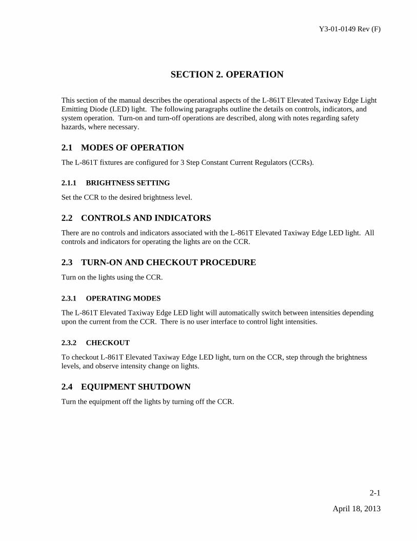
SECTION 2. OPERATION
This section of the manual describes the operational aspects of the L-861T Elevated Taxiway Edge Light Emitting Diode (LED) light. The following paragraphs outline the details on controls, indicators, and system operation. Turn-on and turn-off operations are described, along with notes regarding safety hazards, where necessary.
2.1 MODES OF OPERATION
The L-861T fixtures are configured for 3 Step Constant Current Regulators (CCRs).
2.1.1 BRIGHTNESS SETTING
Set the CCR to the desired brightness level.
2.2 CONTROLS AND INDICATORS
There are no controls and indicators associated with the L-861T Elevated Taxiway Edge LED light. All controls and indicators for operating the lights are on the CCR.
2.3 TURN-ON AND CHECKOUT PROCEDURE
Turn on the lights using the CCR.
2.3.1 OPERATING MODES
The L-861T Elevated Taxiway Edge LED light will automatically switch between intensities depending upon the current from the CCR. There is no user interface to control light intensities.
2.3.2 CHECKOUT
To checkout L-861T Elevated Taxiway Edge LED light, turn on the CCR, step through the brightness levels, and observe intensity change on lights.
2.4 EQUIPMENT SHUTDOWN
Turn the equipment off the lights by turning off the CCR.

Y3-01-0149 Rev (F)
2-2
April 18, 2013
This page intentionally left blank.
Y3-01-0149 Rev (F)
3-1
April 18, 2013
SECTION 3. PERIODIC MAINTENANCE
3.1 INTRODUCTION
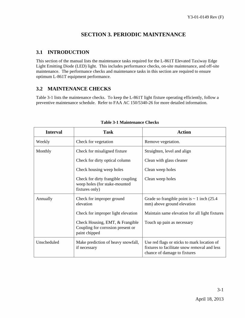
This section of the manual lists the maintenance tasks required for the L-861T Elevated Taxiway Edge Light Emitting Diode (LED) light. This includes performance checks, on-site maintenance, and off-site maintenance. The performance checks and maintenance tasks in this section are required to ensure optimum L-861T equipment performance.
3.2 MAINTENANCE CHECKS
Table 3-1 lists the maintenance checks. To keep the L-861T light fixture operating efficiently, follow a preventive maintenance schedule. Refer to FAA AC 150/5340-26 for more detailed information.
Table 3-1 Maintenance Checks
Interval Task Action
Weekly Check for vegetation Remove vegetation.
Monthly Check for misaligned fixture
Check for dirty optical column
Check housing weep holes
Check for dirty frangible coupling weep holes (for stake-mounted fixtures only)
Straighten, level and align
Clean with glass cleaner
Clean weep holes
Clean weep holes
Annually Check for improper ground elevation
Check for improper light elevation
Check Housing, EMT, & Frangible Coupling for corrosion present or paint chipped
Grade so frangible point is ~ 1 inch (25.4 mm) above ground elevation
Maintain same elevation for all light fixtures
Touch up pain as necessary
Unscheduled Make prediction of heavy snowfall, if necessary
Use red flags or sticks to mark location of fixtures to facilitate snow removal and less chance of damage to fixtures

Y3-01-0149 Rev (F)
3-2
April 18, 2013
This page intentionally left blank.
Y3-01-0149 Rev (F)
4-1
April 18, 2013
SECTION 4. MAINTENANCE PROCEDURES AND CHECKS
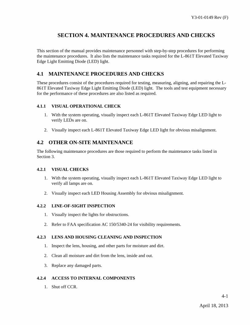
This section of the manual provides maintenance personnel with step-by-step procedures for performing the maintenance procedures. It also lists the maintenance tasks required for the L-861T Elevated Taxiway Edge Light Emitting Diode (LED) light.
4.1 MAINTENANCE PROCEDURES AND CHECKS
These procedures consist of the procedures required for testing, measuring, aligning, and repairing the L-861T Elevated Taxiway Edge Light Emitting Diode (LED) light. The tools and test equipment necessary for the performance of these procedures are also listed as required.
4.1.1 VISUAL OPERATIONAL CHECK
1. With the system operating, visually inspect each L-861T Elevated Taxiway Edge LED light to verify LEDs are on.
2. Visually inspect each L-861T Elevated Taxiway Edge LED light for obvious misalignment.
4.2 OTHER ON-SITE MAINTENANCE
The following maintenance procedures are those required to perform the maintenance tasks listed in Section 3.
4.2.1 VISUAL CHECKS
1. With the system operating, visually inspect each L-861T Elevated Taxiway Edge LED light to verify all lamps are on.
2. Visually inspect each LED Housing Assembly for obvious misalignment.
4.2.2 LINE-OF-SIGHT INSPECTION
1. Visually inspect the lights for obstructions.
2. Refer to FAA specification AC 150/5340-24 for visibility requirements.
4.2.3 LENS AND HOUSING CLEANING AND INSPECTION
1. Inspect the lens, housing, and other parts for moisture and dirt.
2. Clean all moisture and dirt from the lens, inside and out.
3. Replace any damaged parts.
4.2.4 ACCESS TO INTERNAL COMPONENTS
1. Shut off CCR.
Y3-01-0149 Rev (F)
4-2
April 18, 2013
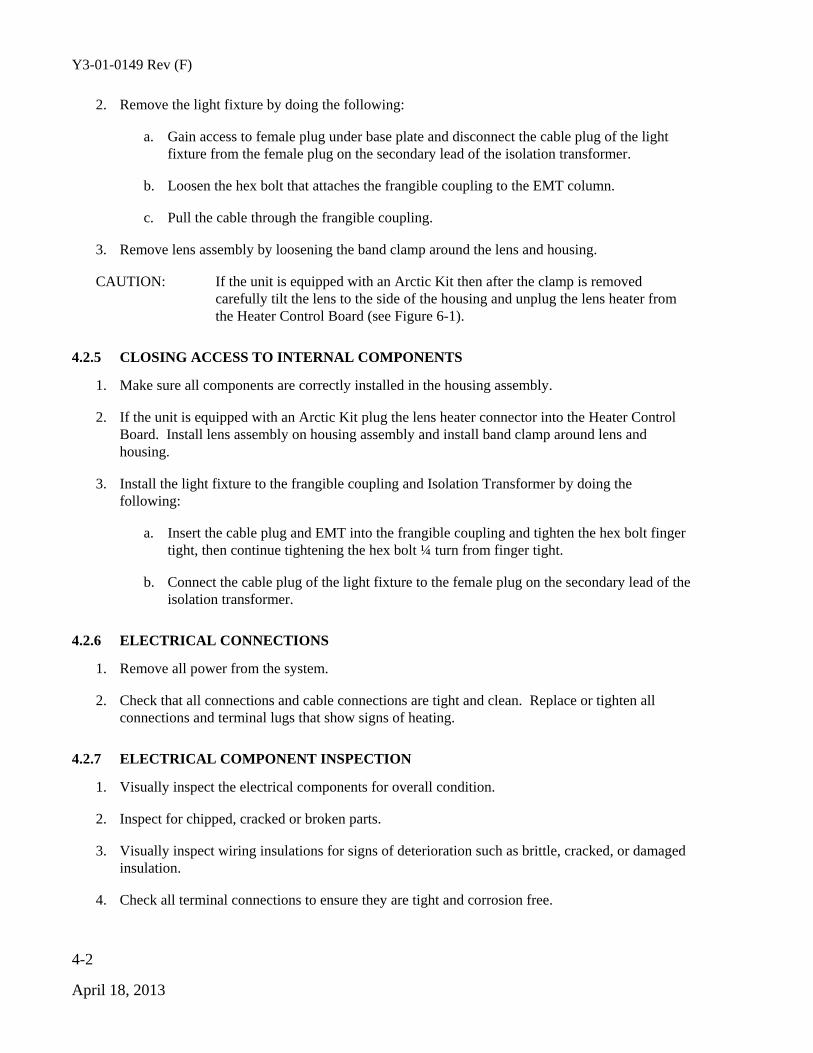
2. Remove the light fixture by doing the following:
a. Gain access to female plug under base plate and disconnect the cable plug of the light fixture from the female plug on the secondary lead of the isolation transformer.
b. Loosen the hex bolt that attaches the frangible coupling to the EMT column.
c. Pull the cable through the frangible coupling.
3. Remove lens assembly by loosening the band clamp around the lens and housing.
CAUTION: If the unit is equipped with an Arctic Kit then after the clamp is removed carefully tilt the lens to the side of the housing and unplug the lens heater from the Heater Control Board (see Figure 6-1).
4.2.5 CLOSING ACCESS TO INTERNAL COMPONENTS
1. Make sure all components are correctly installed in the housing assembly.
2. If the unit is equipped with an Arctic Kit plug the lens heater connector into the Heater Control Board. Install lens assembly on housing assembly and install band clamp around lens and housing.
3. Install the light fixture to the frangible coupling and Isolation Transformer by doing the following:
a. Insert the cable plug and EMT into the frangible coupling and tighten the hex bolt finger tight, then continue tightening the hex bolt ¼ turn from finger tight.
b. Connect the cable plug of the light fixture to the female plug on the secondary lead of the isolation transformer.
4.2.6 ELECTRICAL CONNECTIONS
1. Remove all power from the system.
2. Check that all connections and cable connections are tight and clean. Replace or tighten all connections and terminal lugs that show signs of heating.
4.2.7 ELECTRICAL COMPONENT INSPECTION
1. Visually inspect the electrical components for overall condition.
2. Inspect for chipped, cracked or broken parts.
3. Visually inspect wiring insulations for signs of deterioration such as brittle, cracked, or damaged insulation.
4. Check all terminal connections to ensure they are tight and corrosion free.

Y3-01-0149 Rev (F)
4-3
April 18, 2013
4.2.8 LED HEAD ASSEMBLY REMOVAL
1. Gain access to internal components. Refer to paragraph 4.2.4.
2. Pull LED head assembly from housing assembly.
3. Disconnect 2 power wires from bottom of LED head assembly.
4.2.9 LED HEAD ASSEMBLY INSTALLATION
1. If the unit IS NOT equipped with an Arctic Kit connect power wires to electrical connectors (tabs) on bottom of head assembly. If the unit IS equipped with an Arctic Kit connect 1 power wire to LED head assembly and 1 power wire to wire from Heater Control Board with male (tab) connector. The wire from the Artic Kit with a female connector is connected to the other male connector tab on the LED head assembly.
2. Close access to internal components. Refer to paragraph 4.2.5.

Y3-01-0149 Rev (F)
4-4
April 18, 2013
This page intentionally left blank.

Y3-01-0149 Rev (F)
5-1
April 18, 2013
SECTION 5. CORRECTIVE MAINTENANCE
5.1 CORRECTIVE MAINTENANCE
5.1.1 INTRODUCTION
This section of the manual provides onsite corrective procedures in order to diagnose, isolate, and repair malfunctions and faults that may be found in the L-861T Elevated Taxiway Edge Light Emitting Diode (LED) light in its operational environment. Field repair is limited to the replacement of easily replaceable components.
5.1.2 TEST EQUIPMENT REQUIRED
The following test equipment is required to perform the onsite corrective maintenance procedures:
Standard tool kit
Multi-meter
5.1.3 TROUBLESHOOTING PROCEDURES
The L-861T Elevated Taxiway Edge LED light must be operated as described in Section 2. When a fault or malfunction occurs, corrective maintenance is required by an onsite technician to isolate and correct the problem. The following items should be checked/verified before other troubleshooting/maintenance procedures are performed:
Check all cables are connected
Check all AC power connections are intact
If the above do not correct the malfunction, refer to Table 5-1.
CAUTION: When removing and replacing the electronics module, handle with care to avoid damage to discrete components that can be caused by electrostatic discharge. To avoid voltage overload, make sure the power is turned off when the replacement of a module is required.
Table 5-1 Troubleshooting Procedures
Problem Possible Cause Corrective Action
LED not lighting Defective electronic module
Loose wire connection
Deteriorated wire insulation
Replace the head assembly
Tighten wire connections
Replace wires

Y3-01-0149 Rev (F)
5-2
April 18, 2013
Problem Possible Cause Corrective Action
Moisture present in fixture Open and dry the housing assembly. Replace any damaged items
LED too dim Dirty lens
Service life of LED exceeded
Clean lens
Replace head assembly
Ice forming on lens (Optional Arctic Kit Installed)
Defective arctic kit Replace arctic kit

Y3-01-0149 Rev (F)
6-1
April 18, 2013
SECTION 6. PARTS LIST
6.1 GENERAL
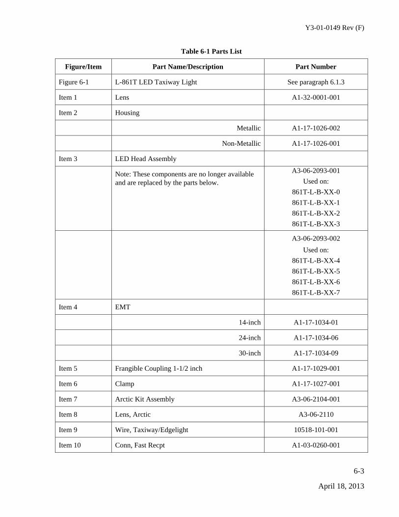
This section of the manual contains the source data of all electrical and selected mechanical replacement parts of the L-861T Elevated Taxiway Edge Light Emitting Diode (LED) light (Table 6-1).
6.1.1 NAME OF PART AND DESCRIPTION
A brief electrical or mechanical description of each component is given in this column.
6.1.2 PART NUMBER
This column gives the designation assigned to a component.
6.1.3 ORDERING INFORMATION

Y3-01-0149 Rev (F)
6-2
April 18, 2013
Figure 6-1 L-861T Elevated Taxiway Edge LED light
1
6
3
2
8
7
4
5
9
Optional Artic Kit
10
11
Y3-01-0149 Rev (F)
6-3
April 18, 2013
Table 6-1 Parts List
Figure/Item Part Name/Description Part Number
Figure 6-1 L-861T LED Taxiway Light See paragraph 6.1.3
Item 1 Lens A1-32-0001-001
Item 2 Housing
Metallic A1-17-1026-002
Non-Metallic A1-17-1026-001
Item 3 LED Head Assembly
Note: These components are no longer available and are replaced by the parts below.
A3-06-2093-001
Used on:
861T-L-B-XX-0
861T-L-B-XX-1
861T-L-B-XX-2
861T-L-B-XX-3
A3-06-2093-002
Used on:
861T-L-B-XX-4
861T-L-B-XX-5
861T-L-B-XX-6
861T-L-B-XX-7
Item 4 EMT
14-inch A1-17-1034-01
24-inch A1-17-1034-06
30-inch A1-17-1034-09
Item 5 Frangible Coupling 1-1/2 inch A1-17-1029-001
Item 6 Clamp A1-17-1027-001
Item 7 Arctic Kit Assembly A3-06-2104-001
Item 8 Lens, Arctic A3-06-2110
Item 9 Wire, Taxiway/Edgelight 10518-101-001
Item 10 Conn, Fast Recpt A1-03-0260-001

Y3-01-0149 Rev (F)
6-4
April 18, 2013
Figure/Item Part Name/Description Part Number
Item 11 Strain Relief Bushing D5975012-013

Y3-01-0149 Rev (F)
7-1
April 18, 2013
SECTION 7. INSTALLATION
7.1 INTRODUCTION
This section of the manual contains general instructions for installation of an L-861T Elevated Taxiway Edge Light Emitting Diode (LED) light at a typical site. Refer to the airport project plans and specifications for the specific installation instructions.
7.2 UNPACKING
The equipment is shipped ready for installation. Handle equipment very carefully to prevent component damage. Unpack the carton upon receipt and check the contents and their condition. Note any exterior damage to the carton that may lead to detection of equipment damage.
7.3 PLACEMENT
This subsection describes the placement of the L-861T light fixtures. Follow he guidelines below, along with FAA specification AC 150/5340-24 and site plans, when placing the L-861T light fixture.
The L-861T light fixture is normally positioned a maximum of 10 feet (3.048m) off the edge of the hard surface of the taxiway, and in a straight line with all other light fixtures on the same side of the runway.
The longitudinal spacing of the light fixtures should not exceed 200 feet (60.96 m) to define the lateral limits of the taxiing paths. The longitudinal spacing of the lights is influenced by the physical layout of the taxiways.
Closer spacing of the light should be provided on short taxiway sections, curves, and entrances to taxiways from runways or aprons.
7.4 INSTALLATION
This subsection provides installation instruction for the L-861T light fixtures.
7.4.1 BASE MOUNTING
L-861T light fixtures can be mounted on an L-867 base plate with a diameter and bolt-hole corresponding to either a 12 inch (304.8 mm) diameter L-867B base or a 16 inch (406.4 mm) diameter L-867D base plate per FAA AC 150/5345-46. The base plate is designed to receive a frangible coupling using a female thread. The standard coupling thread is 1-1/2-12. A gasket is supplied wit the base plate to form a watertight seal between the base plate and the L-867 light base per FAA AC 150-5345-42.
NOTE: Install the base according to FAA Advisory Circular AC 150-5340-24 and site plans.
7.4.2 LIGHT BASE MOUNTING
1. Install the L-867 base on undisturbed soil. If the soil is unsuitable, remove soil to an adequate depth and replace with compacted acceptable material.
Y3-01-0149 Rev (F)
7-2
April 18, 2013
NOTE: In closed duct systems, install in soil conditions with good drainage. Use light bases having a drain hole to prevent water accumulation.
2. Orient the cable entrance hubs of the light base in the proper directions according to site plans
3. Level the light base so that the mounting flange surface is level with the finished grade.
4. With the base at the proper orientation and held at proper elevation, place approximately 4 inches (101.6 mm) of concrete backfill around the outside base.
NOTE: If the concrete backfill is omitted, the earth backfill must be compacted to maintain proper elevation and orientation of the base.
5. Slope the top of the concrete away from the flange portion of the base so the sloped outer edges of the concrete are a surface grade.
6. Connect the field circuit to the appropriate isolation transformer. Refer to Table 1-9.
NOTE: Use a brick to raise the transformer about 3 inches above the bottom surface of the L-867 light base to avoid the possibility of the transformer being partially immersed in water in case water accumulates above the level of the ducts or pipes.
After connecting transformer, check the continuity of the series loop.
7. Wrap the connector joints in the primary circuit with at least one layer of rubber or synthetic rubber tape and one layer of plastic tape one-half lapped, extending at least 1-1/2 inches (3.81 cm) on each side of the joint.
8. Clamp the female secondary plug from the isolation transformer to the L-867 base plate fitting using the clamp device supplied with the base plate.
9. Bolt the base plate with the base plate gasket to the L-867 base using six 3/8-16 stainless steel bolts. Apply a drop of thread lock to each bolt thread, and torques bolts to 100-110 inch-lbs. (11.3Nt-m).
10. Once the base plate is installed, the light fixture assembly is ready to install.
11. Connect the male plug from the light fixture to the female plug on the secondary lead of the isolation transformer by first loosening the frangible coupling hex screw until the coupling if free. Then retighten the hex screw finger tight.
12. Plug the cable into the mating isolation transformer secondary lead.
13. Loosen the hex screw on the coupling to free the coupling. Hand screw the coupling into the base plate hub. Finish tightening the coupling with a wrench.
CAUTION: Do not tighten the coupling if the coupling hex screw is still tight. Damage to the cable connection to the transformer will occur.
14. Tighten the coupling screw that secures the column to the frangible coupling and the adjustable head.
Y3-01-0149 Rev (F)
7-3
April 18, 2013
15. Level the light fixture. Refer to 7.4.3.
7.4.3 LIGHT FIXTURE LEVELING
NOTE: Level the light fixture only after mounting it on the base.
1. Remove clamp and lens, refer to 4.2.4, step 3. Slightly loosen the three cross point screws on the bottom of the housing.
CAUTION: If the Arctic kit is installed, use care when removing the LED lens assembly. There are two wires attached from the heater assembly in the LED housing to the heater element attached to the lens that must be disconnected.
2. Place a level on top of the housing. Level the housing by adjusting the three cross point leveling screws.
3. Install lens and clamp, refer to 4.2.5, step 2.
7.4.4 STAKE MOUNTING (OPTIONAL)
Mount the column light fixtures on 30 inch (762 mm) galvanized steel stake with a fitting attached to the top of each stake to receive the male thread of the frangible coupling. Stake mounting requires cable and connections that are designed for direct earth burial. Install according to appropriate FAA and local contractor specifications.
1. Assemble the stake by attaching the stake hub to the metal stake using two 3/8-16 x ¾ inch hex head screws and 3/8 inch lock washers.
2. Install the stake in 6 inch diameter holes in the ground at a depth of 30 inches so the mounting hub of the stake is level.
NOTE: The top of the stake should be even with the ground within one degree of the vertical. In areas where frost may cause heaving, anchor the stake with concrete and use a permeable backfill material such as sand around the buried electrical components. Cover the top surface with an impervious material to reduce moisture penetration.
CAUTION: Do not drive stakes. Driving stakes may damage the stake and cause light fixture misalignment. Refer to FAA specification AC 150/5340-24.
3. Backfill around the stake with compacted earth passing a 1 inch (25.4 mm) sieve.
NOTE: Use a level to make sure the stake is vertical before backfilling around the stake. Backfill with concrete in case of unstable soil conditions.
4. Make electrical connections by installing the transformer primary cables to the field circuit. Then insert the transformer secondary plug in the cable connectors supports forked tine and attach the cable connector support to the stake hub using ¼-20 x ¾ inch hex head screw and ¼ inch lockwasher.
NOTE: The small hole at the lower end of the stake is provided for a counter poise wire connection.

Y3-01-0149 Rev (F)
7-4
April 18, 2013
5. Install the light fixture on the stake.
6. Level the light fixture, refer to 7.4.3.