A. Runway/Taxiway System · A. Runway/Taxiway System ... - Medium Intensity Approach Lights System...
25
I I ! I i I I I i I ! ! i i ! i i i II. DESCRIPTION OF AIRPORT FACILITIES This chapter describes existing conditions on the airport and in the areas of the City adjacent to the airport. The "existing conditions" described are those which were identified during a comprehensive inventory conducted in October 1987, updated in some key areas to June 1989. Recent studies in connection with the planning of Terminal 4, and in development of the Noise Compatibility Program under Federal Aviation Regulation (FAR) Part 150, have been extensively drawn upon. The reader should be aware that the airport is going through a period of particularly dynamic growth and change; the conditions as described are basically those which pertained in the Fail of 1987; by the time that the report is read, they will most certainly have changed in detail. 1. AIRFIELD A description of each of the components of the airfield is summarized in this section. Included are the airfield pavement system comprising the runway, taxiway and the apron network; the landing and navigational aids associated with specific runways; terminal navigational aids; and runway clear zones, safety areas, and obstacles to air navigation. A. Runway/Taxiway System Runways. The existing airfield consists of two parallel runways: 8L-26R and 8R-26L, oriented east/west with a separation of 3565 feet. The runways and other physical facilities are shown in Figure No. II-1. Runway 8L-26R is 11,000 feet long by 150 feet wide. Runway 8R-26L is 10,300 feet in length. A 200-foot blast pad is provided at Runways 8L, 26R and 8R; and Runway 26L has a 1000 foot blast pad/overrun. The Effective Runway Gradient (ERG) of both runways is 0.23 %. Runway safety areas (ideally 1000 feet by 500 feet according to FAA guidelines) are provided at varying length at each runway end. At the approach end of Runway 8R, a 500 foot by 900 foot safety area is currently maintained; Runway 26L has a 500 foot by 1000 foot safety area; Runway 26R currently has a 500 foot by 680 foot safety area; and Runway 8L currently maintains a 500 foot by 970 foot safety area. II-1
-
Upload
duongtuong -
Category
Documents
-
view
235 -
download
8
Transcript of A. Runway/Taxiway System · A. Runway/Taxiway System ... - Medium Intensity Approach Lights System...

I I !
I i I I I i I ! !
i i !
i i i
II. DESCRIPTION OF AIRPORT FACILITIES
This chapter describes existing conditions on the airport and in the areas of the City adjacent to the airport.
The "existing conditions" described are those which were identified during a comprehensive inventory conducted in October 1987, updated in some key areas to June 1989. Recent studies in connection with the planning of Terminal 4, and in development of the Noise Compatibility Program under Federal Aviation Regulation (FAR) Part 150, have been extensively drawn upon. The reader should be aware that the airport is going through a period of particularly dynamic growth and change; the conditions as described are basically those which pertained in the Fail of 1987; by the time that the report is read, they will most certainly have changed in detail.
1. AIRFIELD
A description of each of the components of the airfield is summarized in this section. Included are the airfield pavement system comprising the runway, taxiway and the apron network; the landing and navigational aids associated with specific runways; terminal navigational aids; and runway clear zones, safety areas, and obstacles to air navigation.
A. Runway/Taxiway System
Runways. The existing airfield consists of two parallel runways: 8L-26R and 8R-26L, oriented east/west with a separation of 3565 feet. The runways and other physical facilities are shown in Figure No. II-1.
Runway 8L-26R is 11,000 feet long by 150 feet wide. Runway 8R-26L is 10,300 feet in length. A 200-foot blast pad is provided at Runways 8L, 26R and 8R; and Runway 26L has a 1000 foot blast pad/overrun.
The Effective Runway Gradient (ERG) of both runways is 0.23 %.
Runway safety areas (ideally 1000 feet by 500 feet according to FAA guidelines) are provided at varying length at each runway end. At the approach end of Runway 8R, a 500 foot by 900 foot safety area is currently maintained; Runway 26L has a 500 foot by 1000 foot safety area; Runway 26R currently has a 500 foot by 680 foot safety area; and Runway 8L currently maintains a 500 foot by 970 foot safety area.
II-1

Taxiwa)rs. Both runways are served by parallel taxiways a.pd a series of exit taxiways to facilitate efficient ground movements of aird-aft.' Taxiway "X' , located east of Terminal 3, is an existing crossover taxiway connecting the north side and south side of the al~eld. New crossover Taxiway "W" connecting the eastern ends of the runways, is under construction.
Aprons. There are approximately 64,000 SY of apron associated with the 12 gates atTerminal 1, approximately-*, ,q 120,000 SY serving the 18 gates at Terminal 2 and approximately 278,000 SY serving the 34 gates at Terminal 3. A large apron area is located between the east cargo building and Terminal 1; this meets the needs of cargo aircraft using the east cargo building, and provides overflow parking for passenger aircraft.
General aviation apron areas for the FBO's are ~ two locations. The first is on the northwest side of the airport, just south of Runway 8L-26R and adjacent to the two FBO facilities (Sawyer Aviation and JIMSAIR). Both Sawyer Aviation and JIMSAIR have apron areas of approximately 44,000 SY.
The second FBO apron area is located on the southwest side of the airport, south of Runway 8R-26L and adjacent to Cutter Aviation facilities. There is a 29,000 SY apron associated with this facility.
There are additional GA apron areas located on the northwest side of .the airport, north of Runway 8L-26R, including tie-down, corporate hangar and T-hangar apron areas. The aprons to the south of Runway 8L-26R, and adjacent to the FBO's are leased to the FBO's.
The Air National Guard, located on the south side of the airport, main ,tains an apron adjacent to those facilities.
Pavement Strength, Conditions, and Markings. Both runways have a grooved asphalt surface and are in good condition. Runway 8R-26L has precision instrument approach markings, and Runway 8L-26R has non-precision instrument approach markings.
Table II. 1 shows the individual runway strengths for the two runways.
B. Landing and Navigational Aids
Information on the existing landing and navigational aids (NAVAIDS) at the airport was obtained from the FAA Airway Facilities personnel. Three specific components of NAVAIDS are addressed - instrument approaches and visual landing aids for specific runways, terminal navigational aids, and lighting.
1 Runway 8L/26R has a dual parallel taxiway from Taxiway "X" to the general aviation transient parking area opposite intersecting Taxiway B3. Runway 8R-26L currently has a single parallel taxiway; however, the Master Plan Update will address the provision of unrestricted two-way taxiway flows.
II-2
I I I I I I I I I I I I I I I I I I
I I I I I I i I I I I I I !
i I I I
" ', ', : ', ,~.1 . . . . . . . . . I ] l . . . . . . . ' ' . . . . . . . t ~ .- : T : [ I [ / I I [ E . . . . . . . . . I i i i i i i , , ~ . . . . . . . . . . . . ~ - i~ -~ - -L~ , . ~ ,. .. [ :
, , ~ x ~ [] ~ ~ " , [] _UyLI L.J ^,,?,~< ~ . .- . ~ \ - - . . ~ _- I : . . . . . . . . I - - - - - T - - ~' "' ~" I L .................................................................. ;..:.:.., 1 % " % , ~ I
' ~ . . . . . o o o o ~. " ° { ~ ~ ~ ~ ~ < ~ j ....................................................................................... ~ ~ , , ..................... o o ~olF_7, ' ~ l \ i ~ : ' " " ~ ~,~ ,:
~ ~ ~ ° °z/ ~ t ' .----- ..... ~------' ~i 3 ° , ......... , i ~ - - - "-,. / - . . . . . . . . . . . . . . ' ( " ~ ' ~ ] ,..";: ' ~ ' " . ~
J//lll B.R,L.- TAXIWAY BB - - - . , , . ~ , B ,~, L, . . . . L - - - - ' . . . . . ~ . . . . J : ] . . . . . r -
" - ~ ~ . . . . . . . . . . . . . . . . ~ . . . ~ . -- P . . . . . . 1 ~ ~ ~li " ~ Y
- • : .~t-:. ,,~ ' , { ~ , , r-~ ~ : "" ~ ....... ~ "" ' ~ '~
~ 3 - - - - ~ ~ .......... i .......... ::::-:..'. = - ..................... ,...:. .................. ,.~- ............ , ....................... ...<:... .......... ~ " . . . . . . . . . ;<' ........................................................................................... H F...- . . . . . . . . " ................
AIR I ~ . . . . . . . . . , . . . . . . . . ~ ~ l ~ . . . . L ~ % ~ ~ ~ - - ~ %~'%" %%%
_ = L I . . . . ~ . & L _ - ~ - ', I AIR CAR~O ~ ~ ~ "~ ~
~ ~ , ' - " ~ ~ .,
. . . . . . . . . . . . I ,o° o o - 0 - ° 0 - : ° o . . . . . . . . . . . . . . ~ o o ~ ° ~7 ' o- ] ( o- o o - ? . / . . . . . . ~ , . ,
_ ~ - - - - - ~ . . . L T - ' ~ ~ - - ~ M . . . . , . . . . . . . . - . . . . . . . / ~ - - = ~ - - ~ - - - ~
~ L :~%~EI~L L
~ + - 0(0 CUITER AVIATION ' . i I / + / + "
OLD TO~
800 16(10 OI I i ; I [
400 1200 /
P H O E N I X S K Y H A R B O R I N T E R N A T I O N A L A I R P O R T M A S T E R P L A N U P D A T E
E x i s t i n g A i r p o r t F a c i l i t i e s
F i g u r e I I - 1
, ! v

I I I
Table II.l
PAVEMENT STRENGTHS
Runway
I I I
Wheel Configuration 8R-26L 8L-26R
Single 30,000 30,000
Dual 200,000 200,000
Dual Tandem 400,000 400,000
Dual Dual Tandem 620,000 620,000
I I I
Source: Airpo r t /Fac i l i t y Directory, U.S. Department of Commerce, October 1987.
Table 11.2
LANDING AND NAVIGATIONAL AIDS
Designated Runway Existing Facility (I*
8L REIL, VASI-4 MLS
8R ILS CAT I, MALSR REIL, VOR/DME
26L REIL, VASI-6, L0C BC, V0R
26R REIL, VASI-4, VOR MLS MALSR
Future FAA Facility Plan
I I I I I I
Legends: REIL MALSR VASI ILS MLS VOR DME BC LOC
- Runway End Identifier Lights - Medium Intensity Approach Lights System with Sequence - Visual Approach Slope Indicators - Instrument Landing System - Microwave Landing System - VHF Omnidirectional Range - Distance Measuring Equipment - Back Course - Localizer
(t) As of October 1987.
II-3
Navigational Aids by Runway. There are five published instrument approach procedui'es for PHx serving specific runways utilizing both on-site and off-site NAVAIDS. A listing of the navigational facilities for each runway is provided in Table 11.2.
Runway 8L. The visual runway landing aids include a 4-bar Visual Approach Slope Indicator System (VASI-4), and Runway End Identifier Lights (REIL). The runway is scheduled for installation of a Microwave Landing System (MLS).
Runway 8R. This runway is provided with a Category I Instrument Landing System (ILS). A Medium Intensity Approach Systemwith Sequence Flashers (MALSR) also serves as a component of the ILS, in addition to the REIL.
Runway 26L. This runway includes a VASI-6 system and REIL.
Runway 26R. The visual runway landing aids include a VASI-4 system and REIL. The runway is scheduled to receive a MALSR, and an MLS in the 1989-90 timeframe.
Lighting. Runway 8L-26R is equipped with Medium Intensity Runway Edge Lighting (MIRL), and Runway 8R-26L is equipped with High Intensity Runway Edge Lighting (HIRL).
All taxiways are equipped with Medium Intensity Edge Lighting (MITL).
Terminal Aids. NAVAIDS in the airport vicinity include the Salt River VORTAC (SRP), 6-1/2 miles to the east, and the Papago (PQO) and Rio Salado (RSZ) Non-Directional Beacons 1 and 4 miles east, respectively.
The terminal aids also include an Airport Surveillance Radar (ASR). The present ASR-8 is to be replaced by a ASR-9 in the near future.
The low level wind shear alert system (LLWAS) currently includes seven sensors; however, five additional sensors are planned.
The Airport has three remote transmitter/receiver facilities (RTR). The first RTR is located on the roof of Terminal 3. The second RTR currently near 22nd Street is to be relocated to an undetermined site, and the third is located on the southside of the airport, east of Taxiway E.
C. Obstacles and Clear Zones
FAR Part 77 defines the standards used for determining obstructions in navigable airspace around an airport. The obstructions are defined as objects which penetrate the imaginary surfaces around the airport, as established in Part 77. Imaginary surfaces include approach surfaces, primary surfaces, horizontal surfaces, conical surfaces and transition surfaces. The dimensions of the approach and primary surfaces are defined based on the type of runway to which they relate.
II-4
i I I I I I I I I I i I I I
I I I I I

I I I I i !
I I I I !
i I I I !
I I I
(Existing Runway 8R is a precision instrument runway, Runways 26L and 26R are • instrument non-precision runways, and Runway 8L is a visual runway.)
The most recent Obstruction Chart (OC 322) for the airport was published in October 1987. Information from this chart is presented in Table 11.3, which identifies obstructions located within the approach surfaces of individual runways and within the primary surfaces.
2. PASSENGER TERMINALS
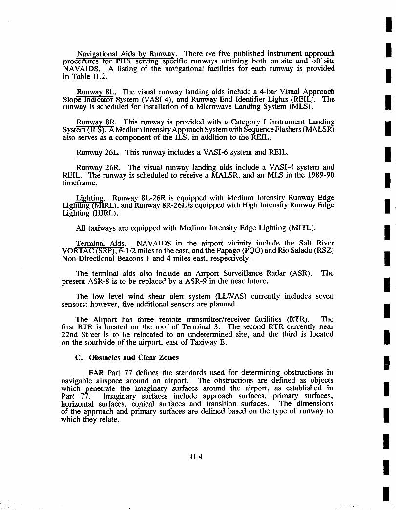
The existing terminal area at the airport includes three domestic unit terminals and an international terminal facility. The terminals are located along an east-west axis between the two parallel runways that serve the airport. The terminals are connected by Sky Harbor Boulevard and by a pedestrian walkway, portions of which are covered. The location of the terminal buildings is shown in Figure No. 11-2.
The domestic terminals are numbered from west to east; their numbers reflect ..... their relative ages. Terminal 1, dedicated in 1952, is the smallest and oldest of the domestic terminals, followed by Terminal 2, which opened in 1962. Both have since undergone major expansion and renovation. The international terminal, a facility which also houses airport police, ground transportation, and security offices, is located between Terminal 2 and Terminal 3, the newest and largest of the unit terminals, dedicated in 1979. A new Terminal 4 is under construction on a site east of Terminal 3; the first phase of Terminal 4 is scheduled to open in late 1990.
The existing terminals collectively contain approximately one million square feet of functional floor area. Drawings and tenant lease data furnished by the airport were assembled and the approximate sizes of existing functional spaces in each domestic terminal were scaled off. Also, design development plans for Phase 1 of the future Terminal 4 were reviewed to determine the approximate areas which that facility would provide. The results of the inventory of existing space and of planned future facilities are presented in Table 11.4 in a format which categorizes functions according to their usage and revenue producing potential.
A. Terminal 1
Terminal I is a one-level facility consisting of an older main building enclosing ticketing and concession functions, and a series of newer passenger holdrooms that are connected to the main building and connected to each other by a secure, exterior covered walkway. Baggage handling and baggage claim functions occur outside the main building, largely under the shelter of metal canopies.
11-5

Table II.3
OBSTRUCTIONS TO IMAGINARY SURFACES
I I !
Obstructions (feet MSL)
Runway Approach S u r f a c e Primary Surface
8L (34:1) Tree (1150) 2 Light Standards (1138 highest) 0L Hangar (1123)
OL Blast Fence (1116)
Vent on Building (1126)
26R (50:1)
(34:1)
Tree (1203) 2 Roads (1153 highest) Ground (1135) Light Standard (1162) 3 Poles (1204 highest) Antenna on OL Tower (1471)
Ground (1135) Road (1142)
8R (50:1) None Ground (1108)
26L (50:1)
(34:1)
Antenna on Tower (1548)
None
!
I I I !
I I !
Note: OL = O b s t r u c t i o n Light
II-6
I I I I I !
I i

I
I
I
RAL AVIATION--.~~L . ~ ~ ~ ~ ~ - /
C " ) c ' )c _ _ . TAXIWAY "BB" _ _ . TAXIWAY "BB" B.R.L.
~ TRACON EXECUTIVE . . ~ T E R M I NAL
~ b ~ ~ - - - - - - - t ~ " - " ~ , ~ h - - h - n <
- - X - -
AIR CARGO BUILDING
PARKING STRUCTURE
- ,
APRON ~il~ TE~
B.R.~.
TAXIWAY "C"
B. R. L__. _ _
-- S "~ "~ ~ --~ "-~ ---- ~ -- --I
I PARK I NG
(
uJ
, _ _ , = \ \ \ \ \ \ ,, ~ ~ 1 ~ i = = ' _ L ;
r--- ~ J
, i - - ,=, - - ,
____ I~ i I,.
--9
B . R . L . ~, :
EMPLOYEE PARKING
X X
f o' ; 2 " i " " £ =
7
!lgl
J /
/
P H O E N I X S K Y H A R B O R I N T E R N A T I O N A L A I R P O R T M A S - r - E R P L A N U P O A T E Existing Terminal Facilities
Figure 11-2

m m m m m m n m n m mm m
Table II. 4
EXISTING AND ~ D DO~STIC TKII~I, FACIT.'rT'rES I
• i ,i, ml I I mm m
Existing Existing Existing Future
Terminal 1 Terminal 2 Terminal 3 Terminal 4
Phase 12
L.F. S.F. L.F. S.F. L.F. S.F. L.F. S°F.
AIRLINE REVENUE SPACE
Ticket Counter 198 1,728
Ticket Counter Passenger Queuing 1,498
Ticket Office and Support Space 7,523
Outbound Baggage 5873
Baggage Claim/Claim Office 240 4,9603
Inbound Baggage Delivery 8002
Operations and Maintenance 9,007
Departure Holdrooms 19,284
VIP /Airline Clubs 0
270
3904
2,700 363 3,630 344 3,440
2,700 5,289 5,160
7,127 13,996 12,760
9,225 34,320 50,756
9,2604 550 19,420 690 21,482
3,256 25,790 36,026
29,270 71,5385 82,555 35,982 82,106 50,300
5,078 12,357 3,640
Subtotal--Airline Revenue 45,387 104,598 268,446 266,119
NON-AIRLINE REVENUE SPACE
Food and Beverage:
Food Preparation
Restaurant and Snack Bar
Cocktail Lounge
Misc. Food and Bey.
876 9,522 19,551
797 9,998 12,603
797 6,231 8,915
209 915 1,268
Total Food Service 2,679 26,666 42,337
other Concessions:
News and Tobacco 0 0 2,551
Gift and Apparel 1,160 3,676 9,381
Barber Shop & Shoe Shine 30 530 72
Bank 88 700 255
Rental Car Counter/Offices 60 768 168 1,665 180 2,147
Advertising Displays 108 165 576
Flight Insurance 0 0 136
Lockers 25 100 138
Telephones 449 707 1,386
Other 1,789 9,573 11,461
180
Subtotal--Non-Airline Revenue 7,096 43,782 70,440 46,737
Total--Revenue Space 52,483 148,380 338,886 312,856
1As of October 1987.
2Based on Design Development report by DWL Architects Planners, Inc., June 1987.
3Exterior covered space. This does not include the proposed U.S. Air extension scheduled for 1988.
4Does not include baggage claim area expansion of approximately 7,000 square feet under construction.
totals do include the "temporary" concourse, scheduled for removal when Terminal 4 is opened.
5Does not include America West baggage transfer facilities under construction.
The

Table II.4 (Cont'd)
EXISTING ANDPLARNED DOMESTIC TERMINAL FACILITIES 1
Existing Existing Existing
Terminal 1 Terminal 2 Terminal 3
L.F. S.F. L.F. S.F. L.F. S.F.
Future
Terminal 4
Phase 12 L.F. S.F.
PUBLIC NON-REVENUE SPACE
Circulation:
Ticket Counter
Baggage Claim
Concourse
Other (non-secure)
Public Restrooms:
Secure Restrooms
Non-secure Restrooms
Other Public Areas:
USO and Traveler's Aid
Nursery
1,866 4,320 8,960 7,200
8003 4,855 7,194 19,800
1,187 44,239 69,456 70,200
9,025 19,890 87,952 100,371
1,500 2,560 7,040 7,200
1,370 2,926 3,705 4,260
300
Total--Public Non-Revenue Space
NON-PUBLIC NON-REVENUE SPACE
Airport Administration
Airport Police/Security
Fire Exits
Bldg. Maintenance and Mechanical
Building Structure
Unfinished Space
15,748 78,790 184,607 209,031
- 1,313 22,097 -
560 1,152 18,021 24,576
362 24,847 67,291 85,245
3,485 7,635 18,927 20,219
- - - 22,054
Total--Non-Public Non-Revenue 4,380 34,947 126,336 152,094
Total Terminal Building Area 72,611 262,117 649,829 673,981
1As of October 1987.
2Based on Design Development report by DWL Architects Planners, Inc., June 1987.
3Exterior covered space.
m m m m mm m m m m m m m m m m m mm m m

I ! !
I !
i I !
I I I I !
I I I !
I I
At the time of inventory (October 1987), Terminal 1 served Southwest Airlines, which at the time operated nine jet carder gates. Three regional airlines -- Golden Pacific, States West, and Mesa -- also operated in Terminal 1, but did not require secure holdrooms because their commuter passengers do not undergo security screening. These commuter passengers, relatively few in number, waited in the commuter ticket lobby until ground level boarding at Gates 10 and 11 at the west end of the terminal. Southwest's passengers, in contrast, boarded jet aircraft through ground-level application loading bridges which extend from the holdrooms to the planes. The number of gates has since been increased to 12.
B. Terminal 2
Terminal 2 consists of a linear two-level building accommodating ticketing and baggage claim areas, a central three-level concessions building, and a long concourse pier with a second level along roughly half its length.
Ticketing and baggage claim occurs at the enplaning/deplaning roadway level, while outbound and inbound baggage is handled at a lower level, accessible by tugs to the aircraft apron via ramped service drives that tunnel under portions of the terminal.
The concessions lobby connects the ticketing/baggage claim terminal element to the concourse pier, and provides a large area for seating and circulation within a perimeter of retail shops and food and beverage concessions. The lobby has a mezzanine level for offices and airline clubs. A lower basement level contains concessions service and storage space.
Improvements recently completed in Terminal 2 include extension of 2nd level concourse, a new addition to the baggage claim lobby (approximately 7,000 square feet) and renovation and upgrading of the baggage conveyor systems.
C. Terminal 3
Terminal 3, the newest and largest of the existing terminals is a five-level building accommodating passenger processing, a two-level concourse extending to the north, a two-level concourse extending to the south, and a temporary one- and two-level concourse connected to and parallel to the south concourse.
The main passenger processing building contains ticketing and baggage claim lobbies on its lowest level, the "street. level" (the same level as the enplaning/deplaning roadway that skirts the length of the building on the north and south sides).
The second level of the building includes baggage handling facilities, mechanical and storage space. The third level the "passenger level," provides concessions and circulation to and from the concourses. The fourth level consists of office area mezzanines surrounding the two-story high spaces of the circulation/concession lobbies below; airport administration offices are located
II-9

on this mezzanine level. accessible to vehicles from building.
The fifth level is the roof parking deck, which is the multi-leveled parking garage that adjoins the
Escalators and elevators convey passengers between the street level and the passenger level of the terminal. Bridges connect the passenger level to the north and south concourses. The third and most recently-constructed concourse, that which exclusively serves America West Airlines, is connected at its north end by a long walkway to the north end of the south concourse. Motorized carts are operated by America West to convey passengers along the 600-foot length of the walkway.
In 1989, six airlines and two regional carders operated in Terminal 3. Of the terminal's 34 gates, almost half were operated by America West.
The two concourses on the south side are occupied by American Airlines and America West. The north concourse serves Continental, Delta, Eastern, and Northwest Airlines. The 80,000 square foot temporary concourse is scheduled for removal when Terminal 4 opens.
To facilitate America West's baggage transfer in its hubbing operation, a new baggage transfer facility has been constructed adjacent to the connector between the America West concourse and the south concourse.
D. Terminal 4
The Terminal 4 complex currently under construction is located between cross Taxiways X and W. It was planned and committed prior to commencement of the master plan update. The terminal complex is configured as a four level unit terminal serving multiple two-story pier concourses along its north and south sides.
The Terminal 4 core building is positioned between the east and westbound lanes of Sky Harbor Boulevard and is served by two level enplaning and deplaning curbsides along its north and south elevations. Baggage claim and rental car functions are located at the lower curbside level. Enplaning, ticketing and baggage check are located at the second or mid level of the terminal. The third level provides passenger circulation to the concourses and contains food, beverage, and retail concessions.
Enclosed passenger transfer bridges, spanning the two-level curbsides, provide circulation from the third level to multiple two story airside pier concourses, on the north and south sides of the terminal. Security checkpoints are located in the entrances to the transfer bridges.
Eight two-story pier concourses are ultimately planned for T-4 in a configuration providing 4 concourses along the north and 4 concourses along the south sides of the terminal core. The concourses are interconnected by elevated, enclosed transfer bridges with moving walkways and circulation aisles for airline carts. These bridges intersect with the main connector bridges
II-10
I I !
I ! i i i
I
I !
I !
I I I I I I I I

I I
I I I I i I i i !
I i I
i I I !
I
linking the terminal and concourses. The apron level of the pier concourses houses airline ramp operations in accordance with the requirements of the various carriers. The second level of the concourses is devoted to passenger departure lounges, concessions and public restrooms.
Phase I development of Terminal 4 proposes construction of the terminal core building, including three levels of parking structure above the terminal, and the development of two north and two south pier concourses.
E. International Terminal
The international terminal, located between Terminal 2 and Terminal 3, contains approximately 10,800 square feet of enclosed building area, includin.g a small inspection facility which is used for processing international arnwng passengers. Due to the limited number of international flights arriving at Sky Harbor today, much of the space in this building is used for other purposes, including office space for customs and airport police, security badging and ground transportation.
3. SURFACE TRANSPORTATION SYSTEM
A. Regional Access
Existing Facilities
The terminal facilities and primary landside components at the airport are located between the parallel east-west runways along a "spine" road system which runs from one end of the airport to the other. Access from points west of the airport is via 24th Street, a north-south arterial which forms the western boundary of the airport and intersects with various east-west streets leading to the downtown and north and west Phoenix. Access from 1-17/I-10 from the southwest and southeast, respectively, is by 24th Street with ramps at Buckeye Road which provides east-west entrance into the airport. The primary existing highway facilities are shown in Figure No. 11-3.
Traffic from the east and north approach the airport from the Hohokam Expressway (44th Street and 48th Street) which forms the eastern boundary of the airport.
The growth of the Phoenix metropolitan area has resulted in a nearly even distribution of traffic entering via the east and west entrances. This represents a change from only four years ago when 60 percent of the traffic entered by the west entrance (24th Street), with 40 percent from the east (40th Street).
II-11

Future Facilities
The major expansion of the Phoenix freeway system already in various stages of planning, design, or construction will result in significant changes to the access system to Phoenix Sky Harbor International Airport.
As a result of the completion of Squaw Peak Expressway/I-10 west of the airport, traffic from northwest and downtown Phoenix approaches the airport by a freeway spur off of 1-10 directly into the airport by Buckeye Road. Traffic from the north approaches the airport from the Squaw Peak Expressway/l-10 and utilizes the same grade separated spur into the airport. As a result, the use of 24th Street, which is scheduled to be relocated approximately 1,300 feet to the west of its present alignment, will no longer be a primary route into the airport. Access from the southwest (1-17) would continue to be via the ramps off of 1-10 which intersect with Buckeye Road.
Access from the east is by Sky Harbor Boulevard, intersecting with 40th Street and the Hohokam Expressway. Major changes are anticipated in the roadway configurations in this area, changes which are currently under design (1989).
B. Terminal Area Circulation
The principle public roadway traversing the airport is Sky Harbor Boulevard which provides access to the terminals. Sky Harbor Boulevard is 2.5 miles long and links Squaw Peak Parkway/l- 10 on the west with the Hohokam Expressway on the east. From 1-10 to Terminal 3, Sky Harbor Boulevard consist of four lanes--two in each direction. From Terminal 3 eastward to the Hohokam Expressway, Sky Harbor Boulevard has three lanes in each direction.
Although Sky Harbor Boulevard has been configured with conventional traffic flow at each entrance, the center segment has been developed with east-bound roadways on the north side of the terminal and west-bound roadways on the south side of the terminal. This facilitates a crossing of the roadways approximately one mile east of the 1-10 interchange and one mile west of the Hohokam Expressway.
Access to Terminal l is provided by a series of roadways which lead from Sky Harbor Boulevard eastbound and westbound and form a two-lane, one-way loop roadway. Egress to the west is via Buckeye Road, while traffic headed to the east must exit by bypassing Terminal 2 before rejoining Sky Harbor Boulevard.
Terminal 2 is served in a manner similar to that of Terminal 1 with roadways which exit off of Sky Harbor boulevard, approach the terminal and then rejoin Sky Harbor Boulevard in order to exit the airport eastbound or westbound.
Terminal 3 is centered between the eastbound and westbound roadways of Sky Harbor Boulevard. To provide for the return movement, loop roadways are provided at each end of the terminal.
II-12
I I I I I !
i I I I I !
I i i I I !
I

I I I !
I I I I I I I I I I I I I I
I I I I I I I I I 1 I I I . . . . . . . . I I : : : ; ' ' ' - : - ' . - ' ; ; : i : , : : : : = : : : : : : : : : : l ::::=l]:::e:::::~,iillliiiilfllil:::~:::::iJr:.il...:::: :_ ~:t
r ~ = ~ n ,~UST,,~ DEVE,_0,,Zm LC S~ A,~A U. ,_....==-___~ ~ [ GENERAL AVIATION I] . .R-Z¢':-- . . . . . . . . . . . .
........................................................................................
o o o o o o ~ o o o o o o
- * t - - - - - # - - - - - -
FENCE B R L TAXIWAY "BB" B L.. TAXIWAY "BB" i ....... i
~ @@00 ~ ~ T.ACO. ExECUT,wTERMINAL 2 S T R U C T U R E 2 ,232 SPACES . ; - ; . . . . . . . . "- ~ - ~ T E R M I N A L 4 " TE"i~L __ . . . . . . . . . . . . . . . . ~- -=~" PA,~ ,G UNDER C O N S T R U C T I O N
~ xk\\\, f, _ HARBOR ~ .~N~,
• [ ~ ] . . - l ....................... ::::" " - ~ }'~ ; .......... ... .................... ;: .................. ; ;~ '-, ........... ' ' ° ~ ; ; ~ , ~ r ..... " "~:' "-'::::~: ................................ i I
- - ] 1 ~ , ' ~ -
- - - ' - ~ , , ~ _ ~ ..... v y ~ - - ~ ~ r ~ " ~ - ~ - ~ ~ > .................... :::::::::::::::::::::: ............................................... :!~ /
~ i r ] ~ I I I . . . . . . . . . . . A P R ~ 'd~L~ ~ L ~ERMINAL 2 ~ ! ~ _ j ~ ' ~ X , / P~N~LOIY~£E : [--]
RTV ~ r l L r l i ~ - i ~ - - x - - f - x ; - ~ - ~ - - , ~ ' ,. T E R M I N A L I L O T "~L ~l~.l~ j ' k , / . o
~ ~1~:] I ~= ' : f ' - - ......... ~ T I N A L 3 STRUCTURE HIGH PROFILE V E H I C L E LOT:, ~ ,..- \ ~ ' " ) TAX'" '~ "C" 2 ,316 SPACES 2 , 2 5 2 SPACES ~ '
. . . . . . . ~ i - - 0 0 - - - - i l i - - - - - o ~ 0 - - 0 -- ~-~--. --0 . - - - -~ - -~ - - - - - - ~ . . . . . . . . . . . . . . . . . . . . . . . . . ' . . . . * . . . . . . . . . . . . . . . . . . . . . . . . _ ~ _ _ ~ _ _ _ _ . _ _ _ _ ~ _ _ _ _ _ ~ m _ _ - - ~ m . . . . _~__
0 , - j~c, , , , z A : ~ . . ~ s ~ . . ,~,c - ' ..... -
_ _ - . . . . v ( ~ I , t - - . . . . . . . . ~ . . ~ : - - . . . . . . '~. <
~ . .~=
0 8 0 0 1 6 0 0 I i I ; I [
400 1200
P H O E N I X S K Y H A R B O R I N T E R N A T I O N A L A I R P O R T M A S T I : : I q P L A N U P D A T E
Airport Access System and Parking Facilities
Figure 11-3

I I I I I I !
I i i i i i i I I !
I
In addition to Sky Harbor Boulevard and the terminal roadways, numerous other roads, including Buckeye Road and various "frontage" roads, provide access to the cargo area, remote public parking lots, the general aviation terminal and FBO's and various employee parking lots.
C. Curbside
Each of the three existing terminals has an independent curbside system tailored to the specific configuration of the terminal (See Figure No. 1I-4). The two lane roadway leading to Terminal 1 widens to provide two through lanes plus a wide curb lane on the terminal side and on an outer lane for public transportation vehicles. A single curb of approximately 470 lineal feet is available for private vehicle with the initial segment serving the departing passengers while the second segment serves arriving passengers. The outer lane on the left side of the two through lanes has a total of 360 lineal feet for taxis, limousines, buses, vans, and courtesy vehicles.
At Terminal 2, the approach roadway widens to form two roadways--an inner roadway for direct access to the terminal by private car and an outer roadway to serve bypassing traffic and various courtesy and shuttle bus services. The inner roadway provides two through lanes and one loading/unloading zone. The effective curb length for privately operated vehicles is 680 feet in length with the first segment opposite the ticket counters serving departing passengers and the second segment adjacent the bag claim area serving the arriving passengers. The outer curb is used by shuttle buses serving the remote parking lots, the inter-terminal shuttle, and off-airport rental cars, and hotels. In addition to these curbs, an additional curbside area is provided just east of the terminal to serve taxicabs, and scheduled, shared ride vans. These two curb areas provide a total of 960 lineal feet for public transportation vehicles at Terminal 2.
Terminal 3 is a two-sided terminal with curb space provided on both the north (eastbound) side of the terminal as well as on the south (westbound) side. On the north side, the initial segment of the available 450 lineal feet serves the departing passenger while the second segment serves the arriving passengers for the traffic approaching from the west.
Along the westbound roadway on the south side, the configuration is reversed with the initial segment being signed for "arriving" passengers and the second segment for "departing" passengers. This configuration is due to the fact that in Terminal 3, the west half of the terminal is occupied by airline ticketing while the east half is used for bag claim. In addition to the curbside roadway, the curb along the outer roadway is used for the inter-terminal shuttle, taxis, unscheduled limousines, and scheduled, shared ride vans. All other vehicles use in the inside curb. This use of the outer curb plus curb length along the parking structure to the east provide a total of 940 feet to serve public transportation vehicles.
11-13

D. Parking
The development of three, and soon four, independent terminals at Sky Harbor International Airport, has resulted in a dispersal of the public parking facilities throughout the airport. At Terminal 1, a 422 space surface lot is available w i t ch the loop roadway serving the terminal.
At Terminal 2, a two-level parking structure was completed in i985. A portion of this structure on the lower level is set aside for short term (hourly) parking. As a result, there are 560 spaces for hourly parkers and 1,672 spaces for daily (longer term) parkers.
The largest single concentration of public parking is currently available at Terminal 3--the busiest terminal. The parking structure just east of the terminal, together with rooftop parking on top of the terminal has a total of 2,316 hourly parking spaces available to serve those arriving and departing Terminal 3. An additional 252 spaces are provided in a "high profile vehicle" surface lot just east of the parking structure.
At the time of inventory, there were two satellite/shuttle lots in use, Lot C located south of Buckeye at the westend of the airport, and the larger east lot north of Sky Harbor Boulevard at 40~h Street. These lots have since been closed, and a replacement, 3,000 space shuttle lot has been opened west of 24th Street at the west end of the airport. Free shuttle bus service connects to the terminals.
In addition to these on-airport public parking facilities totaling 8,102 spaces, numerous companies, primarily located west and northeast of the airport offer off-airport parking at generally reduced rates with free shuttle bus service to the airport.
E. Rental Car Operation
Five rental car companies currently lease rental car counters in each of the three terminals. As part of their leases, four of these companies are allotted a fixed number of ready car and return spaces in parking facilities adjacent to each of the three terminals. This permits an air passenger returning a rental car to pick-up and return a car directly at any terminal rather than to a central, remote location. At present, there are a total of 590 ready-car/return spaces shared by the four companies at Terminals 1, 2 and 3. In addition to those ready-car/return lots, a washing and fueling station for each of the companies is located on the ground floor of the parking structure adjacent to Terminal 3.
The primary maintenance and vehicle storage area for three of the companies is located "off airport", west of 24th Street. Only one company currently operates its service and storage facility on airport--west of the terminals near the cargo complex.
II-14
I I i i I ! !
I I !
I ! !
I I I !
I

I I I I I I I I I I I I I I I I I I
In addition to these on-airport rental car companies, there are many smaller companies located off airport--generally to the west and northwest.
F. Commercial Service
Numerous companies provide other types of ground transportation services, These include taxicabs, and unscheduled and scheduled, shared ride limousines which vary from a schedule time/scheduled route method of operation to an "on demand" service to any destination (much akin to a taxicab system of operation but at a lower charge per person). Because of the relatively low population density of Phoenix and the extent of the metropolitan area, these services are used by only a minor segment of those arriving and departing the Airport.
4. CARGO FACILITIES
Air cargo/freight facilities at the airport are located on the west side of the airport, just to the north of Runway 8R-26L. The facilities include two 780' x 80' north-south buildings, with approximately 62,000 SY apron adjacent to the west. A third building oriented east-west was constructed on the north side of the apron subsequent to the October 1987 Inventory.
The majority of tenants truck freight back and forth from passenger aircraft parked at the terminal buildings. Several of the tenants of the west building fly all-cargo aircraft into PHX and park on the cargo apron adjacent to their facilities. This latter group includes Federal Express, Burlington Northern, Airborne Freight, and Emery Air Freight. These cargo aircraft park on the apron areas to the west of the west cargo building and to the east of the east cargo building.
5. AIR NATIONAL GUARD
The 161st Air Refueling Group of the Arizona Air National Guard (ANG) is located on a 50-acre site on the south side of the airport, south of Runwa), 8R/26L. The unit has a mission of providing air refueling support to aircralt operating out of Luke AFB, Davis AFB, Kirkland AFB, March AFB, and Tucson International Airport, as well as keeping one aircraft on 24-hour alert as part of the Strategic Air Command national defense program.
The unit is equipped with 8 KC-135E tanker aircraft, which flew approximately 160 operations per month, or 2000 operations per year of a total of 7597 operations by military aircraft at PHX in 1986.
Facilities include 2 large hangars (Total 107,300 SF) which are equipped to provide full maintenance services for the unit. Other facilities include administration, recreation, and health services in support of the 913 personnel, 265 of whom are full-time personnel. The apron area is approximately 53,000 SY. A "hush-house" for out-of- frame engine tests was completed in 1985.
II-15

6. GENERAL AVIATION
Three major FBO facilities operate at the airport: YlMSAIR, Sawyer Aviation, and Cutter Aviation. YlMSAIR and Sawyer Aviation facilities are located on the west side of the airport, just south of Runway 8L-26R; and Cutter Aviation is located on the south side of the airport, just south of Runway 8R-26L and west of the ANG facility. (See Figure No. II-~.) The facilities available in each of these areas are detailed in Table II.5.
In addition to these FBO's, an Executive Terminal, owned and operated by the Airport, is located at the east end of the G.A. terminal area south of 8L-26R.
At the time of the inventory, these four facilities accommodated approximately 56 based aircraft.
The airport owns genera~ aviation facility on the north side of the airport, north of Runway 8L-26R. There are 32 existing executive hangars and 10 corporate hangars m this complex, with six new executive hangars p~anned for future construction.
The airport also provides storage for genera~ aviation based aircraft. There are 128 T-Hangars, consisting of 100 small T-hangars and 28 large T-hangars (all occupied), located on the west side of the airport both north and south of Runway 8L-26R. There are 25 covered tie-downs (all occupied) and 153 tie-downs (112 occupied).
7. ,OTHER AIRPORT FACILITIES
A. Airport Rescue and Firefighting Facility (ARFF)
The airport ARFF facility (formerly called the CFR facifity} is located directly to the east of the Terminal 3 parking structure, alongside Taxiway "X". (See Figure No. II-1.) The faci|ity includes a five-bay structure and adjacent canopy. Operations at the airport require tbiat the ARFF facility provides an Index D capability, according to FAA criteria. The apparatus currently housed at the facility surpasses Index D requirements, and actually meets Index E requirements, which would suffice for increased operations by B-747 aircraft.
a FAR Part 139 establishes requirements for ARFF vehicles, response times, and agent discharge rates, according to the size of aircraft served. Index D covers aircraft less than 200 feet long in regular service (5 scheduled departures).
11-16
I I I I I I I I I I I I I I I I I I I

Table 11.5
INVENTORY OF GENERAL AVIATION FACILITIES I
Tenant FBO's
JIMSAIR
Office Space
6,915 SF
Hangar Space
33,148 SF
Apron Space
44,000 SY
Based Aircraft
30
Sawyer Aviation
C u t t e r Aviation
8,460 SF 29,870 SF 44,000 SY
19,300 SF 68,000 SF 29,000 SY
29
22
1 !
i
Total FBO Space 34,675 SF
Executive Hangars by lease:
8 - 3000 SF
ii - 3600 SF
3 - 3900 SF
131,018 SF
24,000 SF
39,600 SF
11,700 SF
117,000 SY
Min. of 1 in each
Min. of 1 in each
Min. of 1 in each
6 - 5690 SF = 2,640 SF
Total Executive Hangar Space 2,640 SF
Corporate Hangars by lease:
31,500 SF
106,800 SF
SRP 4,326 SF 12,154 SF
FBI 3 7,382 SF 2,450 SF
DPS 4,326 SF 12,154 SF
AMCOR 4 3,553 SF 15,600 SF
6
4
PMAir 2,376 SF
Greyhound (2 Hangars)
APS 0
3,830 SF
17,800 SF
13,000 SF
ii
2
2
City Hangar- In-Common 96 SF 12,816 SF 5
!
I I
Vacant Hangar 1,848 SF
Total Corporate Hangar Space 22,059 SF
i00 Small T-Hangars 28 large T-Hangars
153 Tie-Downs 25 Covered Tie-Downs
3,039 SF
92,843 SF
I00 28
105 25
IAs of October 1987. mConstruction to be completed in 1987/88. 30ffice space is vacant. 4Land lease only. AMCOR owns the hangar.
II-17

B. Air Traffic Control Tower and Other FAA Facilities
The Air Traffic Control Tower (ATCT) is located in a separate building directly to the west of Terminal 3. (See Figure No. I1-1.) The facility includes a one story structure housing the tower administrative offices, and a 183-foot tall structure including a tower cab of 400 SF.
The FAA Terminal Radar Approach Control (TRACON) facility is located in a separate building at a site on the west side of the airport. (See Figure No. II-1.)
C. Fuel Storage and Distribution
The fuel supply is located in three separate fuel storage areas. The principal airline, facility, located in the northeast corner of the airport, includes two 30,000 barrel Jet-A tanks (2,520,000 total gallor~s). This facility, owned by the airlines, is operated by a third party (DynAir). New airlines at the airport pay ,an entry fee to gain access to the system. Fuel from the facility is piped underground to hydrant pits located at all gates at Termhnals 2 and 3 and to 4 gates in Terminal 1. Approximately 4.5 - 5.0 million gallons of fuel is pumped from the facility in a typical month. The only scheduled airline not using the facility at the time of inventory was Southwest, which bought its fuel directly from the City, and fueled its aircraft by tanker trucks.
The City's fuel facilities include two above ground and four below ground areas. The capacity of each of these areas is presented in Table II.6. The total City storage capability is ~2,774,000 gallons. Monthly flowage is approximately 1 million gallons (July 1986 - Jtme 1987).
D. Airport Equipment Maintenance Facilities
The existing City maintenance function occupies a 6.5 acre site on the west side of the airport. This facility is recognized as inadequate to meet maintenance needs, and a new facility at the Mechtronics site is under preparation.
8. AIRSPACE AND, A .~ TRAFFIC CONTROL
The primary concern is the extent to which airspace constraints or operational requirements limit the use of the runway system, ,and hence the operational capacity of the airport. The following description of the airspace environment draws extensively on the FAR Part ~50 Noise Compatibility Program report, pp. 1-14 t~ough 1-17.
I I I I I I I I ! !
! ! ! ! !
II-18
! ! !

I I I
Table 11.6
INVENTORY OF AIRLINE AND CITY FUEL STORAGE FACILITIES I
I l ! !
I I I I I !
I
Location/ No. of Operator Supplier Tanks
Airlines NE Corner
Type of Fuel
City Near DynAir hangar/Chevron
Jet-A
City Near DynAir Hangar/Shell
City
City
North of Air Cargo Ramp-Near Gate 207/ ARCO
City
West of ARC0 Facility Next to Gate 207
South of ARC0 Facility, Near Gate 2071Chevron
Total Storage Capacity (Gallons)
2-30,000 barrel 2,520,000
4-20,000 gallons 80,000
2-20,000 gallons 40,000
4-20,000 gallons 2-50,000 gallons
80,000 100,000
2-25,000 gallons 50,000
2-16,000 gallons 32,000
TOTAL JET-A 2,902,000
AVGAS City South of ARC0 Facility, Near Gate 207/Chevron
4-15,000 gallons 100LL
2-15,000 gallons 80 octane
60,000
30,000
TOTAL AVGAS 90,000
! !
I !
IAs of October 1987.
II-19
A. Airspace Management System
The Federal Aviation Administration has the ultimate responsibi|ity for maintaining a safe and efficient flow of air traffic, and for decisions pertaining to air traffic control at the airport. The elements in FAA's management system are:
,, Albuquerque Air Route Traffic Control Center (ARTCC), usually referred to as Cen te r , controls aircraft flying Instrument Flight Rules .(IFR)across the
multi-state area. The Center has assigned a section of airspace within its area to the Phoenix Terminal Radar Approach Control (TRACON) facifity. The responsibility of this facility, located at the airport, is to control IFR traffic in the Phoenix Airport Radar Service Area (ARSA), which includes Sky Harbor together with civilian and military airports in the area. These are:
Scottsdale Municipal Phoenix-Deer Valley Falcon Field Municipal Chandler Municipal Stellar Airpark Casa Grande Municipal Williams AFB Luke AFB Luke AF Auxiliary Field Number One
The area to the east International MSL.
within 5 miles of Sky Harbor and on the instrument approach areas and west of the airport, constitutes the Phoenix Sky Harbor Airport Control Zone which extends to ,an elevation of 14,5,00 feet
B. Air Traf~e Flows
After entering the ARSA, arriving IFR traffic (which includes most airline and military aircraft, even under VFR conditions) is handed off to TRACON control. TRACON contro|lers direct aircraft to fly either Standard Terminal Arrival Routes (STAR) or specified radar headings.
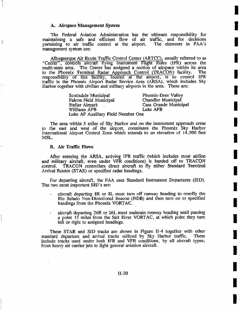
For departing aircraft, the FAA uses Standard Instrument Departures (SID). The two most important SID's are:
aircraft departing 8R or 8L must turn off runway heading to overfly the Rio Salado Non-Directional Beacon (NDB) and then turn on to specified h e a ~ g s from the Phoenix VORTAC.
aircraft departing 26R or 26L must maintain runway heading until passing a point 13 miles from the Salt River VORTAC, at which point they turn left or right to assigned h e a ~ g s .
These STAR and SID tracks are shown in Figure 11-4 together with other standard departure and arrival tracks utilized by Sky Harbor traffic. These include tracks used under both IFR and VFR conditions, by all aircraft types, from heavy air ,cartier jets to light general aviation aircraft.
I1-20'
i !
I I I !
I ! !
I I !
I i I I I I

I I i I !
I i I i !
I !
I I !
i I I
In the same way that aircraft arriving at Sky Harbor are passed by the Center to the local TRACON for control into the local airports, upon passing out of the TRACON airspace or upon climbing through 17,000 feet MSL, departing aircraft are handed off from TRACON to the Center.
C. Other Airports
The TRACON is responsible not only for IFR traffic arriving and departing Sky Harbor International, but also at the region's other airports listed above. Potential interactions between local traffic at these airports and Sky Harbor traffic are described below.
Williams AFB (see Figure II-4) had 536,000 operations in 1986 on three parallel runways aligned in the 12-30 direction, mostly by high performance military training aircraft. Williams protected airspace and traffic patterns overlap those of Sky Harbor.
Luke AFB (see Figure II-4) has two parallel 3-21 runways and experienced 224,000 operations in 1986, including training activity by supersonic jet aircraft. Significant interactions occur between civilian VFR traffic using the Buckeye flyway or the V-16 airway, and military traffic to the south of the AFB.
Scottsdale Municipal Airport is a busy general aviation reliever airport (190,000 operations in 1986). The only instrument approach to the airport from the south, the VOR-A, conflicts with the Payso Hi Two and Drake Eight departure procedures at Sky Harbor.
Stellar Airpark is a privately owned airport located 9 miles southeast of Sky Harbor, and under the Standfield SID departure route. Missed approaches at Stellar could potentially conflict with traffic on the east side of Sky Harbor.
D. Other Airspace Factors
The two major military airfields, Luke and Williams, each have blocks of airspace designated Military Operations Areas (MOA) assigned to them. These are areas of intense military training activity; the designations "MOA" are designed to separate this activity from civilian IFR traffic and to alert civilian VFR traffic that this is an area where concentrated jet training is performed. Prior analyses have indicated that operations to the east of Sky Harbor are constrained by Williams AFB MOA 1.
Additional data on the airspace structure in the Phoenix region is available in the MAG publication "Phase II - Airspace Analysis, Regional Aviation System Plan Update", October, 1984.
II-21

F
I I x \ !
: j .r i , i I ~, @ i
~ " " eCA.E ' . . /
I I \ dJJll~r~ I ~ \ ' b " , /
I ~ A-231 ~ _ "%' ' r. It I . , " , .,, I r ' t ' / / " ".,1 j i i I i SC01 ISDALE t ~ . ~ : , I~K ) \ M,.,,~,,,A,. / l
I LO.E O L E N O A < ~ ' ; : / ~ : ~ \ ~ . , , ~ , ~ . . . . - - - - T I AF6 MUNICIPAL, ' ' ~ I
' + ' ' I ' ' ~' Ttr[ • ~ ~,, t - - , r ~ _ . . . . . = ' , - i - I . .
_ _ +. . . . . . . ,, . . . . . . . , . . ~ 11 , ,~ , . , . f ~ . , . , , . , / / ~ " .._ . . . . . , : i - j I! !LL" ~11"- ]%. P A P A G O I " iijlr'.lJ~lf/ MESA-FALCON
i I ~ + ~" J"-m;_' "" . - \A.M~, Ouw.o~ i " - " ~ i l ' ~ @F,,: .o
~.t "N, ",.A ' S K Y H~I.RBoR T M i.~;.; l
i . / . ~ % / ~ ME DRIAL ~ - - "Fill
I ~ -.oC:= Z~;u.,c,..< / I + I ' \ ~ - . . : \ 5 0 5 10
i R e p r o d u c e d from E x h i b i t ]E Sky H a r b o " I n t e r n a t i o n a l ' ' . . . r n , ~ ~ . ~ . G P IC ~ A L I IN NAUTICAL MILI:S
A i r p o r t N o i s e C o m p a t l b d i t y S t u d y
I , I f P H O E N I X S K Y H A R B O l a I N T E R N A T I O N A L A I F I P O ~ T M A S T E R P L A N U P D A T E
, r , . v . . o e . , . u , e + u . e . I ' ) " __Z'_ S t e t e l l n t e r l t l t e Highways ~ M O A ( M i l i t a r y Operations Ares)
0 A i r p o r t s W i t h o u t H l r d - S u r f s c e d ~ A l e r t A r e a
Runways m S t a n d a r d Instrument Departure i O Airports With Control Towers Route
(~ Airports Without Control Towers m S t a n d a r d T e r m i n a l A r r i v a l
VORTAC Route ~ l N o n d i r e c t i o n a l R a d i o B e a c o n " - - ~ ' V i s u a l A p p r o a c h R o u t e Figure 1 1 - 4