
KTA 3902 (2020-12) Design of Lifting Equipment in Nuclear ...
69
Safety Standards of the Nuclear Safety Standards Commission (KTA) KTA 3902 (2020-12) Design of Lifting Equipment in Nuclear Power Plants (Auslegung von Hebezeugen in Kernkraftwerken) Previous versions of this Safety Standard were issued 1975-11, 1978-06, 1983-11, 1992-06, 1999-06 and 2012-11 If there is any doubt regarding the information contained in this translation, the German wording shall apply. Editor: KTA-Geschaeftsstelle c/o Bundesamt fuer die Sicherheit der nuklearen Entsorgung (BASE) • Willy-Brandt-Strasse 5 • 38226 Salzgitter • Germany Telephone +49-30-18-4321-2907 • E-Mail [email protected]
Transcript of KTA 3902 (2020-12) Design of Lifting Equipment in Nuclear ...

Safety Standards
of the Nuclear Safety Standards Commission (KTA)
KTA 3902 (2020-12)
Design of Lifting Equipment in Nuclear Power Plants
(Auslegung von Hebezeugen in Kernkraftwerken)
Previous versions of this Safety Standard were issued 1975-11, 1978-06, 1983-11, 1992-06, 1999-06 and 2012-11
If there is any doubt regarding the information contained in this translation, the German wording shall apply.
Editor:
KTA-Geschaeftsstelle c/o Bundesamt fuer die Sicherheit der nuklearen Entsorgung (BASE) • Willy-Brandt-Strasse 5 • 38226 Salzgitter • Germany Telephone +49-30-18-4321-2907 • E-Mail [email protected]


KTA SAFETY STANDARD
December 2020
Design of Lifting Equipment in Nuclear Power Plants KTA 3902
CONTENTS
Basic principles ............................................................ 5
1 Scope .................................................................... 5
2 Definitions ............................................................. 5
3 General provisions ................................................ 5
4 Special provisions ................................................. 5
4.1 Lifts in reactor containments ................................. 5
4.2 Cranes, winches, trolleys and load carrying devices with additional requirements .................... 5
4.3 Cranes, winches, trolleys and load carrying devices with increased requirements .................... 6
4.4 Refueling machines for light water reactors .......... 6
4.5 External events (EVA) ........................................... 6
4.6 Ambient conditions ................................................ 6
4.7 Ergonomics requirements ..................................... 6
5 Lifts in reactor containments ................................. 6
5.1 General requirements............................................ 6
5.2 Passenger lifts and lifts used for transporting goods and passengers .......................................... 6
5.3 Lift shaft................................................................. 6
6 Additional requirements for cranes, winches, trolleys and load carrying devices ......................... 8
6.1 Structures .............................................................. 8
6.2 Hoists .................................................................... 9
6.3 Lateral transport drives........................................ 10
6.4 Load carrying devices ......................................... 11
6.5 Electrical equipment ............................................ 12
7 Increased requirements for cranes, winches, trolleys and load carrying devices ....................... 14
7.1 Structures ............................................................ 14
7.2 Hoists .................................................................. 15
7.3 Lateral transport drives ........................................ 16
7.4 Load carrying devices .......................................... 16
7.5 Electrical equipment ............................................ 17
8 Requirements for refueling machines for light water reactors ...................................................... 17
8.1 Structures ............................................................ 17
8.2 Hoists .................................................................. 18
8.3 Lateral transport drives ........................................ 19
8.4 Load carrying devices .......................................... 20
8.5 Electrical equipment ............................................ 20
Annex A: Examples for classification of lifting equipment .................................................. 21
Annex B: Load cases and analytical proofs for lifting equipment ........................................ 23
Annex C: Stress-number diagram for the fatigue analysis of the materials S235 and S355 according to DIN EN 10025-2 .......... 42
Annex D: Stress analysis and stress-number diagrams for the fatigue analysis of the steels 1.4541, 1.4306 and 1.4571 according to DIN EN 10088-2 or DIN EN 10088-3 ............................................... 48
Annex E: Required Performance Levels according to DIN EN ISO 13849-1 for function of safety-related parts of control systems ......................................... 55
Annex F: Regulations and literature referred to in this Safety Standard .................................. 63
Annex G: Changes with respect to the edition 2012-11 and explanations (informative) .... 67
PLEASE NOTE: Only the original German version of this safety standard represents the joint resolution of the 35-member Nuclear Safety Standards Commission (Kerntechnischer Ausschuss, KTA). The German version was made public in the Federal Gazette (Bundesanzeiger) on January 20th, 2021. Copies of the German versions of the KTA safety standards may be mail-ordered through the Wolters Kluwer Deutschland GmbH ([email protected]). Downloads of the English translations are available at the KTA website (http://www.kta-gs.de).
All questions regarding this English translation should please be directed to the KTA office:
KTA-Geschaeftsstelle c/o BASE, Willy-Brandt-Str. 5, D-38226 Salzgitter, Germany or [email protected]

Comments by the editor:
Taking into account the meaning and usage of auxiliary verbs in the German language, in this translation the fol-lowing agreements are effective:
shall indicates a mandatory requirement,
shall basically is used in the case of mandatory requirements to which specific exceptions (and only those!) are permitted. It is a requirement of the KTA that these exceptions - other than those in the case of shall normally - are specified in the text of the Safety Standard,
shall normally indicates a requirement to which exceptions are allowed. However, the exceptions used, shall be substantiated during the licensing procedure,
should indicates a recommendation or an example of good practice,
may indicates an acceptable or permissible method within the scope of this Safety Standard.
KTA 3902 Page 5
Basic principles
(1) The Safety Standards of the Nuclear Safety Standards Commission (KTA) have the objective to specify safety-related requirements, compliance of which provides the necessary precautions in accordance with the state of the art in science and technology against damage arising from the construction and operation of the facility (Sec. 7 para. 2 subpara. 3 Atomic Energy Act - AtG) in order to achieve the fundamental safety functions specified in the Atomic Energy Act, the Radiation Protection Act (StrlSchG) and the Radiological Protection Ordinance (StrlSchV) and further detailed in the Safety Re-quirements for Nuclear Power Plants (SiAnf) as well as in the Interpretations on the Safety Requirements for Nuclear Power Plants.
(2) Based on the Safety Requirements for Nuclear Power Plants (SiAnf) and the Interpretations of the Safety Require-ments for Nuclear Power Plants, this Safety Standard speci-fies the design criteria for lifting equipment. Additionally, lifting equipment shall be erected and operated in accordance with the valid federal and state safety regulations as well as with the regulations of the official accident insurance institutions.
(3) Regarding the danger potential, the design shall be based on
a) additional requirements or
b) increased requirements
for lifting equipment which exceed the general provisions,
as well as
c) requirements for lifts in reactor containments and
d) requirements for refuelling machines
as specified in this Safety Standard in detail.
(4) General requirements regarding quality assurance are specified in Safety Standard KTA 1401.
(5) The requirements for inspection, testing and operation, including specific requirements for quality assurance, are laid down in KTA 3903.
1 Scope
This Safety Standard applies to the design of lifts, cranes, winches, trolleys, load carrying devices and refueling ma-chines of light water reactors, collectively called lifting equip-ment in the following, in as far as they are used in nuclear pow-er plants and meet the special provisions of section 4.
2 Definitions
(1) Parts in the load path
In this Safety Standard, parts shall be deemed to be “within the load path” if they
a) can directly lead to an inadmissible impairment of the lifting capacity of lifting equipment in case of their failure,
or
b) are welded on to a part as per a), where only the area of the welded on component, that influences the stress curve within the component according to a), is considered to be within the load path.
(2) Maximum operational load
The maximum operational load is the load which is moved with the lifting equipment during specified normal operation.
(3) Refueling machines for light water reactors
A refueling machine for light water reactors is that equipment which is directly used to charge the reactor core with fuel assemblies or control rods (e.g. shim or shutdown rods), or to discharge these from the core.
(4) Lifting load
The lifting load is the sum of maximum erection load or maxi-mum operational load and the dead weights of the compo-nents to take up the load to be handled, e.g. bottom block, lifting beam, and the weight of the supporting means, e.g. of the rope.
(5) Load carrying device
Load carrying devices are supporting means, load suspension devices and lifting accessories. They are defined in DIN 15003.
(6) Load shifting
Load shifting is an event where due to failure of one part with-in the double drive mechanism chain or due to failure of a redundant part of the rope drive within a drive chain with safe-ty brake an additional load is applied on the lifting equipment.
(7) Machine parts
Machine parts are axles, shafts, bolts, tie rods and similar parts.
(8) Maximum erection load
The maximum erection load is the maximum load which may be moved by the lifting equipment during the erection phase until commencement of licensed nuclear operation.
3 General provisions
(1) Lifting equipment shall be erected in accordance with the valid general safety regulations, especially the federal and state work protection regulations and the regulations of the official accident insurance institutions.
(2) Lifting equipment shall at least comply with the generally accepted engineering standards.
4 Special provisions
4.1 Lifts in reactor containments
Lifts in reactor containments shall, in addition to the general provisions of section 3, comply with the requirements of sec-tion 5 if their specified normal use extends to the transporta-tion of persons.
4.2 Cranes, winches, trolleys and load carrying devices with additional requirements
(1) If, in the course of transportation of nuclear fuel, other radioactive substances, radioactive components or other loads, a failure of the lifting equipment is expected to lead
a) to the immediate danger of a release of radioactivity with a subsequent radioactive exposure of persons in the plant subjected to an effective dose by inner exposure exceed-ing 1 mSv or to an external exposure exceeding 5 mSv
or
b) to a loss of reactor coolant which cannot be isolated, or to a detrimental effect on, and going beyond the redundancy of, the safety equipment which is necessary to shut down the reactor at any time, to maintain the reactor in the shut-down condition or to remove residual heat, and no dangers as per section 4.3 need be expected.
then, in order to provide adequate protection against damage, the cranes, winches, trolleys and load carrying devices shall meet the additional requirements of section 6 exceeding the requirements of the general provisions of section 3.
(2) The classification of lifting equipment with regard to addi-tional requirements shall be specified within the nuclear licens-ing and supervisory procedure. Examples for this classification and for the procedural steps of classification are given in Annex A.
KTA 3902 Page 6
4.3 Cranes, winches, trolleys and load carrying devices with increased requirements
(1) If, in the course of transportation of nuclear fuel, other radioactive substances, radioactive components or other loads, a failure of the lifting equipment is expected to lead
a) to a criticality accident
or
b) to the danger of a release of radioactivity where the maxi-mum allowable discharge into the atmosphere may be ex-ceeded as laid down in the license or the radioactive expo-sure of individual persons of the population in the nuclear power plant environment may exceed the limit values of the Radiological Protection Ordinance (StrlSchV)
then, in order to provide adequate protection against damage, the cranes, winches, trolleys and load carrying devices shall meet the increased requirements of section 7 exceeding the requirements of the general provisions of section 3.
(2) The classification of lifting equipment with regard to in-creased requirements shall be specified within the nuclear licensing and supervisory procedure. Examples for this classi-fication and for the procedural steps of classification are given in Annex A.
4.4 Refueling machines for light water reactors
Refueling machines for light water reactors shall, in addition to the general provisions of section 3, meet the requirements of section 8.
4.5 External events (EVA)
(1) An analytical proof of the adequate protection of lifting equipment against external events is required provided such requirement also exists for the building.
(2) Exceptions are permitted if it is demonstrated that no effects and damage resulting from the lifting equipment can affect the functional capability of any plant component that is designed against external events.
(3) The adequacy of the protection against external events shall be analytically proven for the lifting equipment without load.
(4) If the lifting equipment is designed for a definite parking position, then the analytical proof is only required for this posi-tion.
(5) The general principles of KTA 2201.4 apply to all exter-nal events.
4.6 Ambient conditions
(1) Ambient conditions, e.g., pressure, temperature, medium, radiological exposure, shall be considered in the design.
(2) The possibility for decontamination, e.g. of the structures, shall be considered in the structural design.
4.7 Ergonomics requirements
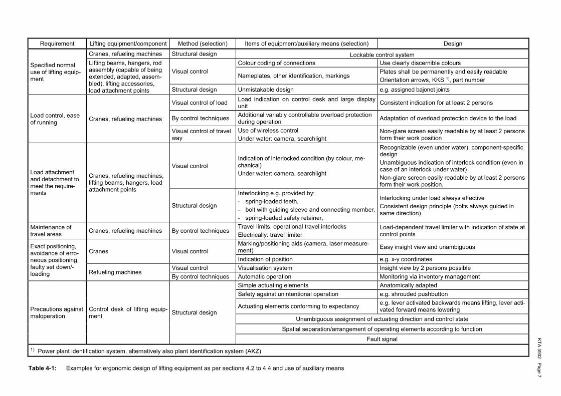
Lifting equipment as per sections 4.2 to 4.4 shall satisfy the design principles of DIN EN 894-1 and DIN EN ISO 12100 leading e.g. to the following requirements:
a) Load carrying devices and their detachable individual items shall be constructed or identified such that confusion of items is excluded.
b) The command, control and monitoring devices as well as identification markings, actuating, connecting and safety elements shall be designed such that
ba) they are compatible both with the usual expectations and the current practice (conformity of expectation),
bb) the operating personnel is able to safely perform and monitor the handling processes at any time.
c) Signals and indications shall be handled to comply with their safety-relevant priority.
d) The safe handling as well as safe attachment and detach-ment of loads shall be supported by technical measures.
Table 4-1 shows typical examples. The technical measures shall be supplemented by administrative measures as regards the organisation of transports as per section 9.2 of KTA 3903.
5 Lifts in reactor containments
5.1 General requirements
Lifts shall meet the requirements of the Directive 2014/33/EU and be provided with a safety level according to DIN EN 81-20.
5.2 Passenger lifts and lifts used for transporting goods and passengers
Passenger lifts and lifts used for transporting goods and pas-sengers shall be
a) connected to a emergency power supply,
b) connected to the alarm system of the nuclear power plant,
c) connected to the intercommunication system such that it is possible to communicate from the cabin with the pertinent permanently manned location,
d) equipped with a specially marked easy-to-open emergency exit.
5.3 Lift shaft
The lift shaft shall be
a) equipped with pressure-equalization openings to all rooms accessible from the lift shaft; the lift cage or the pressure-equalization openings shall be designed against raised ex-ternal pressure such that they can withstand the dangers in accordance with sub-clause 4.3 (1) b),
b) equipped with devices for an emergency exit from which each lift-shaft door is easily accessible,
c) equipped with lift-shaft doors which can be easily unlocked from the inside,
d) designed such that the escape route can be easily recog-nized, and
e) equipped with emergency lighting connected to a continu-ous emergency power supply.
KT
A 3
902
Pa
ge
7
Requirement Lifting equipment/component Method (selection) Items of equipment/auxiliary means (selection) Design
Specified normal use of lifting equip-ment
Cranes, refueling machines Structural design Lockable control system
Lifting beams, hangers, rod assembly (capable of being extended, adapted, assem-bled), lifting accessories, load attachment points
Visual control
Colour coding of connections Use clearly discernible colours
Nameplates, other identification, markings Plates shall be permanently and easily readable
Orientation arrows, KKS 1), part number
Structural design Unmistakable design e.g. assigned bajonet joints
Load control, ease of running
Cranes, refueling machines
Visual control of load Load indication on control desk and large display unit
Consistent indication for at least 2 persons
By control techniques Additional variably controllable overload protection during operation
Adaptation of overload protection device to the load
Visual control of travel way
Use of wireless control
Under water: camera, searchlight Non-glare screen easily readable by at least 2 persons form their work position
Load attachment and detachment to meet the require-ments
Cranes, refueling machines, lifting beams, hangers, load attachment points
Visual control Indication of interlocked condition (by colour, me-chanical)
Under water: camera, searchlight
Recognizable (even under water), component-specific design
Unambiguous indication of interlock condition (even in case of an interlock under water)
Non-glare screen easily readable by at least 2 persons form their work position.
Structural design
Interlocking e.g. provided by:
- spring-loaded teeth,
- bolt with guiding sleeve and connecting member,
- spring-loaded safety retainer,
Interlocking under load always effective
Consistent design principle (bolts always guided in same direction)
Maintenance of travel areas
Cranes, refueling machines By control techniques Travel limits, operational travel interlocks
Electrically: travel limiter Load-dependent travel limiter with indication of state at control points
Exact positioning, avoidance of erro-neous positioning, faulty set down/-loading
Cranes Visual control Marking/positioning aids (camera, laser measure-ment)
Easy insight view and unambiguous
Indication of position e.g. x-y coordinates
Refueling machines Visual control Visualisation system Insight view by 2 persons possible
By control techniques Automatic operation Monitoring via inventory management
Precautions against maloperation
Control desk of lifting equip-ment
Structural design
Simple actuating elements Anatomically adapted
Safety against unintentional operation e.g. shrouded pushbutton
Actuating elements conforming to expectancy e.g. lever activated backwards means lifting, lever acti-vated forward means lowering
Unambiguous assignment of actuating direction and control state
Spatial separation/arrangement of operating elements according to function
Fault signal
1) Power plant identification system, alternatively also plant identification system (AKZ)
Table 4-1: Examples for ergonomic design of lifting equipment as per sections 4.2 to 4.4 and use of auxiliary means
KTA 3902 Page 8
6 Additional requirements for cranes, winches, trolleys and load carrying devices
6.1 Structures
This section applies to the supporting structures of cranes, trolleys and winches.
6.1.1 Design
(1) For the application of this Safety Standard, two verifica-tion methods are permitted:
a) method using a global safety factor (σzul concept) accord-ing to DIN 15018-1
and
b) method using partial safety factors according to the stand-ard series DIN EN 13001.
(2) The simultaneous use of both methods within the entire verification process for a lifting device is allowed only if the parts in question are clearly separated from each other and the transmittal of internal forces within the overall structure can be gathered entirely as well as the load bearing character-istics of the entire structure are ascertained correctly. Where an analytical proof regarding external events is to be carried out, clause 4.5 (5) shall be taken into account.
(3) The following data shall be specified for dimensioning the supporting structures:
a) erection loads including the corresponding working cycles over the intended deployment duration,
b) operational loads including the corresponding working cycles over the intended deployment duration,
c) loads from external events in accordance with section 4.5,
d) ambient conditions in accordance with section 4.6.
6.1.2 Analytic proof
6.1.2.1 Analytic proof using the global safety factor concept according to DIN 15018-1
(1) The stress analysis shall be performed in accordance with Annex B, section B 1.1.1.
(2) The supporting structures shall be classified with re-spect to
a) the maximum erection load: lifting class H1 and loading level group B2 in accordance with DIN 15018-1.
b) the maximum operational load: lifting class H3 and loading level group B3 in accordance with DIN 15018-1.
(3) Where a dynamic factor1 less than that resulting from (2) is to be used, the maximum dynamic load factor occurring during one working cycle shall be determined by means of calculation or experimentally in each individual case. As re-gards the determination of the dynamic factor this dynamic load factor shall be multiplied by a safety factor of 1.12.
(4) A verification of service strength need not be carried out if it can be demonstrated that the number of stress cycles is below 2·104. The number of stress cycles shall be determined in accordance with Annex B, section B 1.2.1.2.
(5) In the case of connections made with preloaded bolts to be re-assembled upon disassembly, the following applies in addition to (4):
a) Where a verification of service strength is to be carried out as per (4), the stress cycles resulting from disassembly
1 In DIN 15018-1 the term “nominal load spectrum factor” is used instead of “dynamic factor”.
and re-assembly operations shall be taken into account in the analysis.
b) Where no verification of service strength is required as per sub-clause (4) and a maximum of 10 disassembly and reassembly operations is carried out, a verification of ser-vice strength may be waived.
c) Where more than 10 disassembly and re-assembly opera-tions are carried out, a verification of service strength shall be carried out independently of the requirements of subcl. (4). In this case, both the stress cycles from operational loadings and from disassembly and re-assembly opera-tions shall be taken into account.
6.1.2.2 Analytical proof using the partial safety factors concept according to the standard series DIN EN 13001
(1) The stress analysis shall be performed in accordance with Annex B, section B 1.1.2.
(2) The supporting structures shall be classified with re-spect to
a) the maximum erection load: stress history class S1 accord-ing to DIN EN 13001-3-1,
b) the maximum operational load: stress history class S3 according to DIN EN 13001-3-1.
(3) The fatigue analysis need not be carried out if the condi-tions according to section 6.3.3 of DIN EN 13001-3-1 so per-mit. The number of stress cycles shall be determined in ac-cordance with Annex B, section B 1.2.1.2.
(4) In the case of connections made with preloaded bolts to be re-assembled upon disassembly, the following applies in addition to (3):
a) Where a fatigue analysis is to be carried out as per (3), the stress cycles resulting from disassembly and re-assembly operations shall be taken into account in the analysis.
b) Where no fatigue analysis is required as per subcl. (3) and a maximum of 10 disassembly and re-assembly operations is carried out, a fatigue analysis may be waived.
c) Where more than 10 disassembly and re-assembly opera-tions are carried out, an analysis for cyclic operation shall be carried out independently of the conditions according to section 6.3.3 of DIN EN 13001-3-1. In this case, both the stress cycles from operational loadings and from disas-sembly and re-assembly operations shall be taken into ac-count.
6.1.3 Design and structural requirements
N o t e s :
(1) Requirements for the design of supporting structures and structural requirements are also contained in DIN EN 1090-2.
(2) Requirements for the structural design of rails, rail connec-tions, track bedding and rail fasteners are also contained in VDI 3576.
(1) When using the global safety factor concept together with an analytical proof according to DIN 15018-1, the design shall be based on DIN 15018-2.
(2) When using the partial safety factor concept together with an analytical proof according to the standard series DIN EN 13001, the design shall be based on the relevant stipulations of this standard series.
(3) Dynamically loaded weld seams shall meet the require-ments of quality level B according to DIN EN ISO 5817 or DIN EN ISO 13919-1. Weld seams primarily subject to static loadings shall satisfy the requirements of quality level C of DIN EN ISO 5817 or DIN EN ISO 13919-1.

KTA 3902 Page 9
(4) Hollow spaces in supporting structures of lifting equip-ment inside the containment shall be equipped with pressure equalization openings for the case of raised external pressure or shall be dimensioned to withstand these pressure conditions.
(5) The preloading of preloaded bolted connections shall be carried out according to the guideline DASt 024 of the German Committee for Steel Construction. The calculated preloading force shall be limited to the nominal minimum preloading force Fp,C* = 0,7 ⋅ fyb ⋅ As.
6.2 Hoists
This section applies to drive mechanisms and rope drives.
6.2.1 Drive mechanisms
This section applies to gear boxes, series gear boxes, series electric hoists, couplings and brakes.
6.2.1.1 Design
(1) The following data shall be specified for the design of drive mechanisms:
a) erection loads including the pertinent working cycles over the intended deployment duration,
b) operational loads including the pertinent working cycles over the intended deployment duration,
c) dead load of the load suspension devices and supporting means,
d) special loads, e.g. loads from the acceptance test, from in-service inspections, from test runs of the gear box, from actuation of the brakes, including the corresponding work-ing cycles over the intended deployment duration,
N o t e :
When using systems to ascertain the braking effect without test load for in-service inspection, see also KTA 3903, Annex D, section D 3.1.
e) duty cycle of the hoist under erection load, operational load and dead load as well as pertinent average hoisting speed and average travel path,
f) ambient conditions in accordance with section 4.6.
(2) The dimensioning of series-produced parts like brakes, brake discs, couplings, shall be based on the design data to be determined in accordance with the corresponding forms of KTA 3903, Annex C.
(3) The roller bearings shall be dimensioned on the basis of the calculation principles of the roller bearing manufacturer. Dynamic loads may be subjected to cubic averaging methods which shall be based on a probability of failure of 3 % to be taken with a1 = 0.44. The maximum test load shall be consid-ered to be the static (continuous) load.
6.2.1.2 Analytic proofs
The analytic proofs shall be performed in accordance with Annex B, section B 1.2.
6.2.1.3 Design and structural requirements
6.2.1.3.1 General
(1) Hoists shall be equipped with an overload protection device which shall be adjusted to no more than 1.1 times the maximum operational load. The tolerance of the overload protection response level relating to the maximum operational load shall not exceed ± 5 %.
(2) Hoists shall be equipped with a meter for counting the running hours or the load collectives. A meter for monitoring
the load collectives is required if the analytic proofs are based on a load collective.
N o t e :
It is presumed that the parameters counted with the load collective meter are adjusted to or transferrable to the assumptions of the design by analysis.
When using a meter that only counts the running time during which the drive mechanism is in motion, 50 % of the indicated time shall be considered full-load hours. When using a meter for load collectives, all loads greater than 10 % of the maxi-mum operational load shall be recorded.
(3) If the weight of the supporting means amounts to more than 30 % of the maximum operational load, then the entire running time of the drive mechanism shall be recorded.
(4) Grey-cast iron bearing housings are not permitted.
6.2.1.3.2 Gear boxes
(1) Shaft-hub linkages with flat, hollow, sunk, tangent and gib-head keys are not allowed.
(2) Shaft hub connections with press fit assembly are permit-ted for series-production hoist gear boxes and series-production electric hoists with rope if they are designed and constructed according to the state-of-the-art.
(3) The offset between two fitting keys shall be at least 120°. The value of the bearing length of the key used in the analysis shall not exceed 1.2 times the shaft diameter.
(4) The design and construction of transmission gears shall meet the following requirements:
a) When calculating the load bearing capacity in accordance with DIN 3990-11, the limits of application and require-ments of this DIN standard shall be taken into account.
b) When calculating the load bearing capacity according to the method of Niemann [2] in accordance with Annex B the following requirements ba) to bg) shall be taken into ac-count.
ba) The ratio of useable face width to pitch circle diameter, b/dw1 shall be smaller than or equal to 1.2 for the case of a rigid pinion shaft supported at both ends.
bb) Longitudinal crowning and profile reduction are permit-ted provided they stay within the size of tooth defor-mation.
bc) In case of a floating support of the transmission gears or if the bearings of the gear transmission are located on the supporting structure or if the requirement under ba) cannot be met, the width factor shall be deter-mined by measurement or by a correspondingly accu-rate numerical analysis.
This numerical analysis shall take into account any de-formation and relocation that are essential with regard to load distribution over the gear width. Furthermore, the numerical analysis shall consider any fabrication deviations and corrections with their true sign.
bd) The normal modulus mn for transmission gears shall normally be equal to or greater than 1/25 of the usea-ble face width, b. If the bearings of the gear transmis-sion are located on the supporting structure or in the case of a floating support of the pinions, the normal modulus mn shall be larger than b/25.
be) No grinding recess is allowed on the side of the tooth.
bf) In the case of ground teeth, protuberance profiles shall be used or the grinding shall be carried out down to the bottom of the tooth with a rounded-off tool head.
bg) Sufficient lubrication shall be ensured. It shall be en-sured that the lubrication has an adequate viscosity at the operating temperature.

KTA 3902 Page 10
(5) Grey-cast iron gear box housings are not allowed except for series-produced electric hoists. The weld seams of welded gear box housings shall satisfy the requirements of quality level C of DIN EN ISO 5817 or DIN EN ISO 13919-1.
(6) The gear box quality shall be chosen such that at zero load the tooth bearing
a) in the case of non-crowned teeth, is at least 60 % of the useable face width in counter direction to the deformation tendency under load
and
b) in the case of longitudinally crowned teeth, is at least 40 % of the useable face width beginning about at the centre of the tooth face and running in counter direction to the de-formation tendency under load.
6.2.1.3.3 Brakes
(1) Two brakes (service brake and auxiliary brake) shall be located on the drive side upstream of the output transmission which shall act independently of each other.
(2) The brakes shall satisfy the requirements of DIN 15434-1. The required braking torque of each brake shall be designed for the maximum operational load.
(3) It shall be ensured that upon standstill of the drive mech-anisms, the maximum operational load is held alone by the service or the auxiliary brake and that the maximum erection load is held by the service and the auxiliary brake, and in both cases with a 2-fold safety. The brakes shall be capable of withstanding the thermal and dynamic operational conditions.
(4) If the service brake fails, the auxiliary brake shall be capable of safely absorbing the increased energy of the sys-tem resulting from the failure condition.
(5) Where the drive is of the non-converter type, the auxiliary brake shall engage during any operational braking after a certain time delay with respect to the service brake. The delay time shall be fixed such that during operational braking at full lowering speed and maximum operational load the auxiliary brake engages at the latest when the lowering speed has reached a residual value of 5 %.
6.2.2 Rope drives
The section applies to ropes, rope sheaves, rope drums, rope end terminations and rope drum hinge connections.
6.2.2.1 Design
(1) The rope drives shall be classified in accordance with DIN 15020-1, in which case the larger of the resulting rope diameters shall be used:
a) for the maximum erection load at least drive mechanism group 1Bm according to DIN 15020-1. If the ratio of rope minimum breaking strength to static rope traction force is at least 3.5, and if ropes are used whose individual strands have a nominal strength up to 1960 N/mm2, the design may be based on drive mechanism group 1Em.
b) for the maximum operational load at least drive mecha-nism group 2m for dangerous transports.
(2) The dimensioning of rope sheaves and wedge sockets shall be based on the design data to be determined in accord-ance with the corresponding forms of KTA 3903, Annex C.
(3) The diameter of the rope drums, rope sheaves and com-pensating pulleys shall be dimensioned at least in accordance with drive mechanism group 2m according to DIN 15020-1.
(4) The rope end terminations shall be dimensioned in ac-cordance with DIN 15020-1.
(5) The rope drum wall thickness shall be calculated using the maximum prevalent dynamic force Smax from the load col-lective of operational conditions in accordance with Annex B, sub-clauses B 1.2.1.1 (2) a) to c). Stress peaks which occur rarely and for only very short periods of time need not be con-sidered since they affect only a fraction of one rope wrap.
(6) Rope drum hinge connections shall be dimensioned on the basis of the load collective of operational conditions in accordance with Annex B, sub-clauses B 1.2.1.1 (2) a) to c) and shall be analyzed in accordance with the design principles of the manufacturer.
(7) The rope clips shall be dimensioned in accordance with SEB 666211 Suppl. Sheet 1, taking the structural circum-stances into account.
6.2.2.2 Analytical proofs
The analytical proofs shall be performed in accordance with Annex B, section B 1.2.4.
6.2.2.3 Design and structural requirements
(1) Grey-cast iron rope sheaves and rope compensating pulleys are only allowed if they are series-produced and are protected against mechanical damage.
(2) The wire rope ends may be fastened as follows:
a) metal socketing in accordance with DIN EN 13411-4.
b) ferrules according to DIN EN 13411-3 provided the ropes have steel cores,
c) asymmetrical wedge sockets with a clamping angle of about 14°, a clamping length equal to 5 times the rope di-ameter and a bending radius at the rope key equal to 1.5 times the rope diameter. The rope key shall be marked with the rope diameter. The wedge socket shall have a breaking strength of at least 85 % of the minimum breaking strength of the rope.
d) clamping plates for fastening rope ends on the drum in accordance with section 6.4 of DIN 15020-1.
(3) The number of wraps assumed during design, but at least two safety windings of rope shall remain on the drum when the load hook is in its lowest position.
(4) Rope drums shall be of the single-layer winding type only. The orderly winding of the rope shall be monitored or be ensured by structural design measures (e.g. rope guide rings).
(5) The weld seams of welded rope drums shall satisfy the requirements of quality level B of DIN EN ISO 5817 or DIN EN ISO 13919-1.
6.3 Lateral transport drives
This section applies to the wheel bearings and wheels, wheel axles and shafts.
6.3.1 Design
The following data shall be specified for the dimensioning of lateral transport drives:
a) running time classification in accordance with Table 5 of the DIN calculation principles for drive mechanisms in lift-ing equipment [7],
b) standard load collective in accordance with Table 6 of the DIN calculation principles for drive mechanisms in lifting equipment [7],
c) running time of the drive motor (in terms of 1 h) in accord-ance with Table 4 of DIN 15070,
d) ambient conditions corresponding to section 4.6.
KTA 3902 Page 11
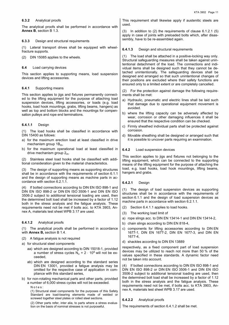
6.3.2 Analytical proofs
The analytical proofs shall be performed in accordance with Annex B, section B 1.3.
6.3.3 Design and structural requirements
(1) Lateral transport drives shall be equipped with wheel-fracture supports.
(2) DIN 15085 applies to the wheels.
6.4 Load carrying devices
This section applies to supporting means, load suspension devices and lifting accessories.
6.4.1 Supporting means
This section applies to jigs and fixtures permanently connect-ed to the lifting equipment for the purpose of attaching load suspension devices, lifting accessories, or loads (e.g. load hooks, load hook mountings, grabs, lifting beams, hangers) as well as top and bottom blocks and the mountings for compen-sation pulleys and rope end terminations.
6.4.1.1 Design
(1) The load hooks shall be classified in accordance with DIN 15400 as follows:
a) for the maximum erection load at least classified in drive mechanism group 1Bm,
b) for the maximum operational load at least classified in drive mechanism group 2m.
(2) Stainless steel load hooks shall be classified with addi-tional consideration given to the material characteristics.
(3) The design of supporting means as supporting structures shall be in accordance with the requirements of section 6.1.1 and the design of supporting means as machine parts in ac-cordance with section 6.2.1.1.
(4) If bolted connections according to DIN EN ISO 898-1 and DIN EN ISO 898-2 or DIN EN ISO 3506-1 and DIN EN ISO 3506-2 subject to additional tensional loading are used, then the determined bolt load shall be increased by a factor of 1.12 both in the stress analysis and the fatigue analysis. These requirements need not be met if bolts acc. to KTA 3903, An-nex A, materials test sheet WPB 3.17 are used.
6.4.1.2 Analytical proofs
(1) The analytical proofs shall be performed in accordance with Annex B, section B 1.4.
(2) A fatigue analysis is not required
a) for structural steel components
aa) which are designed according to DIN 15018-1, provided a number of stress cycles Nσ = 2 ⋅ 104 will not be ex-ceeded,
ab) which are designed according to the standard series DIN EN 13001, provided a fatigue analysis may be omitted for the respective case of application in com-pliance with this standard series,
b) for non-rotating mechanical parts and other parts, provided a number of 6,000 stress cycles will not be exceeded.
N o t e s : (1) Structural steel components for the purposes of this Safety Standard are load-bearing elements made of welded or screwed together steel plates or rolled steel sections.
(2) Other parts refer, inter alia, to parts where a stress evalua-tion on the basis of nominal stresses is not purposeful.
This requirement shall likewise apply if austenitic steels are used.
(3) In addition to (2) the requirements of clause 6.1.2.1 (5) apply in case of joints with preloaded bolts which, after disas-sembly, have to be re-assembled again.
6.4.1.3 Design and structural requirements
(1) The load shall be attached in a positive-locking way only. Structural safeguarding measures shall be taken against unin-tentional detachment of the load. The connections and indi-vidual items shall be designed such that they cannot be de-tached unintentionally. The safeguarding devices shall be designed and arranged so that such unintentional changes of their positions are excluded where their safety functions are ensured only to a limited extent or are completely cancelled.
(2) For the protection against damage the following require-ments shall be met:
a) Hydraulic, pneumatic and electric lines shall be laid such that damage due to operational equipment movement is avoided.
b) where the lifting capacity can be adversely affected by wear, corrosion or other damaging influences it shall be ensured that the respective condition can be checked.
c) Firmly sheathed individual parts shall be protected against corrosion.
d) Movable sheathing shall be designed or arranged such that it is possible to uncover parts requiring an examination.
6.4.2 Load suspension devices
This section applies to jigs and fixtures not belonging to the lifting equipment, which can be connected to the supporting means of the lifting equipment for the purpose of attaching the load, e.g. load hooks, load hook mountings, lifting beams, hangers and grabs.
6.4.2.1 Design
(1) The design of load suspension devices as supporting structures shall be in accordance with the requirements of section 6.1.1 and the design of load suspension devices as machine parts in accordance with section 6.2.1.1.
(2) Section 6.4.1.1 applies to load hooks.
(3) The working load limit of
a) rope slings acc. to DIN EN 13414-1 and DIN EN 13414-2,
b) chain slings according to DIN EN 818-4,
c) components for lifting accessories according to DIN EN 1677-1, DIN EN 1677-2, DIN EN 1677-3, and DIN EN 1677-4,
d) shackles according to DIN EN 13889
respectively, as a fixed component part of load suspension devices may be utilized to reach not more than 50 % of the values specified in these standards. A dynamic factor need not be taken into account.
(4) If bolted connections according to DIN EN ISO 898-1 and DIN EN ISO 898-2 or DIN EN ISO 3506-1 and DIN EN ISO 3506-2 subject to additional tensional loading are used, then the determined bolt load shall be increased by a factor of 1.12 both in the stress analysis and the fatigue analysis. These requirements need not be met, if bolts acc. to KTA 3903, An-nex A, materials test sheet WPB 3.17 are used.
6.4.2.2 Analytical proofs
The requirements of section 6.4.1.2 shall be met.

KTA 3902 Page 12
6.4.2.3 Design and structural requirements
(1) The requirements of section 6.4.1.3 shall be met.
(2) The use of rope slings and chain slings as fixed compo-nent parts of load suspension devices is permitted provided they meet the requirements of DIN EN 13414-1 and DIN EN 13414-2 as well as DIN EN 818-4, respectively, and if both are designed without sheaving and with defined load transmission points.
(3) Fibre ropes and woven bands are not permitted.
(4) Only chains according to DIN EN 818-2 and with an inside width b1 = 1.3 ⋅ d are permitted.
(5) DIN EN 1677-1, DIN EN 1677-2, DIN EN 1677-3, and DIN EN 1677-4 shall apply to the components of lifting acces-sories.
(6) Chain attachment elements and connection parts shall be designed to be irremovable from the hanger and end links.
(7) The elements connecting the rope slings and chain slings to the load attachment points shall be designed to be unambiguously identifiable, where confusion of elements may lead to an unacceptable condition.
(8) Any surface treatment procedure used on chain slings shall be such that no damage occurs to the base material (e.g. hydrogen inclusion).
6.4.3 Lifting accessories
6.4.3.1 General
(1) This section applies to rope slings and chain slings.
(2) Lifting accessories shall be clearly assigned to fixed transport operations and shall only be used for operations they are assigned to.
6.4.3.2 Design
The working load limit of
a) rope slings acc. to DIN EN 13414-1 and DIN EN 13414-2,
b) chain slings according to DIN EN 818-4,
c) components for lifting accessories according to DIN EN 1677-1, DIN EN 1677-2, DIN EN 1677-3, and DIN EN 1677-4,
d) shackles according to DIN EN 13889
may be utilized to reach not more than 50 % of the values specified in these standards. A dynamic factor need not be taken into account.
6.4.3.3 Design and structural requirements
(1) Only rope slings according to DIN EN 13414-1 and DIN EN 13414-2 and chain slings that meet the requirements of DIN EN 818-4 as well as components for lifting accessories according to DIN EN 1677-1, DIN EN 1677-2, DIN EN 1677-3, and DIN EN 1677-4 are permitted.
(2) Rope slings and chain slings are permitted only if both are designed without sheaving and with defined load trans-mission points.
(3) The requirements specified in section 6.4.1.3 shall be met.
(4) The requirements specified in para 6.4.2.3 (3) through (8) shall be taken into account.
6.5 Electrical equipment
6.5.1 General
(1) Safety functions shall be provided which, in case of in-admissible operating conditions or inadmissible excess of
limitations (travel, speed and loads, or a combination thereof), shall effect shutdown of the pertinent drives and prevent drives from starting up. The shutdown of a drive shall include the release of the required brakes.
(2) The control system shall be subdivided into an opera-tional control system and a safety-related control system. The latter shall be independent of the operational control such that in case of specified normal operation, malfunction or failure of the operational control system, the function of the safety-related control system remains effective. In such case, the following shall be satisfied:
a) Functions required for lifting equipment operation, which do not monitor the occurrence of inadmissible operating conditions or inadmissible excess of limitations e.g. travel-ling control command shall be part of the operational con-trol system.
b) The safety-related control system shall monitor the ob-servance of all safety-relevant limit values of lifting equip-ment and, in the case of inadmissible operating conditions or inadmissible excess of limitations, shall transfer the lift-ing equipment to safe condition. Functions classified into Performance Levels c, d and e according to Annex E, shall be part of the safety-related control system.
c) Whenever software-based safety-related control systems are employed, only software shall be used, that has been developed and established satisfying the requirements for the software of class 2 I&C systems acc. to DIN EN IEC 62138, section 6.
(3) When realizing the functions required for safe operation of lifting equipment the requirements of DIN EN ISO 13849-1 shall basically be met, in which case the Performance Levels shall be determined to Annex E, section E 2. Table E-1 as-signs Performance Levels to the respective typical functions. Deviations from the Performance Level laid down in Table E-1 shall be justified in each individual case.
N o t e :
The requirements of DIN EN ISO 13849-1 include that the failure behavior of mechanical components used for connection and ac-tuation of sensors involved in the execution of safety functions shall be taken into account.
In lieu of the Performance Levels laid down in Table E-1 ac-cording to DIN EN ISO 13849-1, the Safety Integrity Levels (SIL) defined in the standard series DIN EN 61508 may be used, in which case the requirements as per SIL 2 according to DIN EN 61508 are deemed to be equivalent to the require-ments as per Performance Level “d“ according to DIN EN ISO 13849-1 and the requirements as per SIL 3 are deemed to be equivalent to the requirements as per Performance Level “e“.
(4) Safety-related functions of Performance Level “c“ to “e“ according to DIN EN ISO 13849-1 shall be effective inde-pendently of the operational control functions. Faults in opera-tional control functions shall not render these safety-related functions ineffective. Safety-related functions of Performance Level “d“ shall be effective at least in category 3 and safety-related functions of Performance Level “e“ in category 4 ac-cording to DIN EN ISO 13849-1. The reaction times of all safe-ty-related functions shall be sufficiently short to fulfil the re-spective safety task.
(5) When planning, designing and executing the safety-related functions of Performance Levels “c” to “e” according to DIN EN ISO 13849-1 the requirements contained in DIN IEC 61513 for functions of category B shall be met.
(6) For all limiting and interlocking functions required by this Safety Standard positively opening control switches operating to the closed-circuit current principle or another technique shall be used to obtain equivalent safety like in the case of positively opening control switches.

KTA 3902 Page 13
(7) Closed working cabins and operating cabins in cranes inside the controlled area shall be connected to the alarm system and the safety illumination system of the nuclear pow-er plant such that alarms are perceived and escape routes are discernible.
(8) Measures shall be taken to make possible the unambig-uous identification of the current version of hardware and software utilized for functions classified into Performance Levels c, d and e according to Annex E.
(9) Measures shall be taken to ensure that the in-service functional tests in accordance with KTA 3903 can be per-formed without manipulation of the electrical equipment (e.g. loosening of wire connections, removal of equipment parts). In this case, it shall be ensured that the entire signal path can be covered by the in-service functional tests.
Testing equipment shall be provided with an access-enable program so that it can be activated by authorized personnel only.
Where testing equipment not provided with automatic return is used, its activation shall be annunciated by a signal. De-activated testing equipment shall not have any influence on the safety-related functions of Performance Levels “c” through “e” according to DIN EN ISO 13849-1 even in the case of fault.
For the in-service tests of safety travel limiters of hoists and lateral transport drives a release device shall be provided which, when activated, makes it possible for the crane opera-tor, upon release of the travel limiter, to leave the travel way in opposite direction of movement at creep speed. The release device for leaving the safety travel limiter shall be of the lock-ing-type and be provided with automatic return (e.g. key-operated pushbutton) and be positioned such that a second person (within the sense of the 4-eyes principle) can be em-ployed to operate the release device.
6.5.2 Requirements for the electrical equipment
(1) It shall be possible to activate the crane switch only if it has been released by means of a key-operated switch or a similarly safeguarded switching device.
(2) The three-phase current supply shall be equipped with a phase-sequence relays and a phase conductor monitor. Where these monitoring devices respond, it shall not be pos-sible to switch in the crane switch, and where the lifting equipment is operating, the crane switch shall switch off. The response of these monitoring devices shall initiate an alarm signal at the control points.
(3) The response of overcurrent protective devices shall switch off only the pertinent motor branch circuit, unless sev-eral motors are available for the same function which must be switched off simultaneously. The coils of hoist motors shall be equipped with sensors for monitoring the temperature. The response of overcurrent protective devices shall trigger an alarm signal at the control points.
(4) The actuation of the overload protection shall interrupt the hoist movement and trigger an alarm signal at the control points. Upon acknowledgement of the alarm signal lowering shall be possible.
The overload protection shall be set at no more than 1.1 times the maximum operational load.
The response tolerance of the overload protection relating to the maximum operational load shall not exceed ± 5 %.
For the putting of lifting equipment into operation the switching threshold shall be adapted to the swinging behaviour when lifting the load.
(5) The hoists shall be equipped with a meter for monitoring the running time or the load collective in accordance with section 6.2.1.3.1. Measures shall be taken to prevent data
loss (e.g. by redundant data storage, storage on fail-safe me-dium or regular data saving).
(6) It must be possible to actuate the hoist brakes individual-ly and independently of each other; the brakes shall be con-nected to all phases. In the case of non-converter operated drives, the auxiliary brake in accordance with para. 6.2.1.3.3 (5) shall engage after a certain time delay after the service brake.
A warning shall be triggered at the control points if the brake lining thickness of the service brake is less than the minimum thickness and if the service or the auxiliary brake do not open or close (activity of the brake bleeding device). In case of electromagnetic compact brakes it is permitted to derive the indication that the brake does not open or close from one switch only. Sliding rotor motors with integrated brakes are exempted from the requirement regarding a non-opening or non-closing alarm.
N o t e : When using systems to ascertain the braking effect without test load for in-service inspection, see also KTA 3903, Annex D, sec-tion D 3.1.
(7) If non-converter drives are used, the lateral transport drives and hoists shall have at least one creep speed aside from the nominal speed. Accelerations and decelerations shall be kept low when changing speed.
(8) In the case of converter drives, monitoring shall be re-quired such that the lifting equipment is stopped at zero posi-tion of the control system and maintained at standstill and that, at activation of the control system, movement is in the right direction.
(9) In the case of electrically driven load suspension devices respective position indications shall be provided at the control points (e.g. grab opened, grab closed).
(10) It shall be ensured by means of electrical interlock that the control command for detachment of an attached load (e.g. control signal “Open grab“ cannot be released unintentionally or at positions which are not permitted as regards safety.
(11) Where the orderly winding up of the rope on the drum cannot be ensured by structural measures, monitoring is re-quired. Where monitoring shows an inadmissible deviation, a standstill shall be effected and an alarm signal be released at the control points.
6.5.3 Limiting functions
(1) To limit the crane and trolley movement as well as the lifting and lowering movement, operational travel limiters in accordance with Table E-1 shall be provided. Additional safety travel limiters shall be provided in accordance with Table E-1.
a) for lateral transport drives where no mechanical travel way end limiters are provided,
b) for hoists at the top and bottom end of hoist travel way.
(2) Where electronic travel way measuring systems are used for safety-related functions of Performance Levels “c” through “e” according to DIN EN ISO 13849-1,
a) the adjustment function (preset) of these systems shall be released by technical measures (e.g. key-operated switch-es),
b) redundant travel way measuring systems shall basically be designed and arranged such that a simultaneous mechan-ically caused failure of the transmitters is excluded,
c) a monitoring device for the detection of a sensor failure due to mechanical reasons is required in the case of re-dundant travel way measuring systems that cannot meet the requirement according to b) and in the case of non-redundant travel way measuring systems,
d) a slip-free drive is required if absolute value encoders are used.

KTA 3902 Page 14
(3) Where the operational travel limiter responds, its slow-ing-down path shall be dimensioned such that drive standstill is effected prior to reaching the safety travel limiter position. Upon response of the operational travel limiter, movement in the respective opposite direction shall be possible.
(4) As long as the safety travel limiter is actuated, no move-ment of the lateral transport drive or hoist shall be possible. For in-service inspections measures shall be taken to make movement in opposite direction possible upon running into the safety travel limiter. The response of the safety travel limiter shall trigger an alarm signal at the control points.
(5) It shall be ensured by technical measures that mechani-cal travel limiters and safety travel limiters can only be ap-proached with the allowable speed. Measures to limit and monitor the allowable speed at the lateral transport drive and hoist end positions are not required if
a) for lateral transport drives
aa) the mechanical travel way end limiter is designed for the nominal speed
or
ab) the slowing-down path provided for at response of the safety travel limiter is dimensioned such that the me-chanical travel limiter is not approached or only at the allowable speed,
b) for hoists the slowing-down path provided for at response of the safety travel limiter is adequately dimensioned.
(6) If, for safety reasons, the lifting and lateral movements need be partially or entirely restricted (e.g. movements above the fuel pool), this shall be ensured by a respective interlock function. The activation of the interlock shall trigger an alarm at the control points.
6.5.4 Control and alarm systems
6.5.4.1 Control system
(1) An interlock shall be provided to ensure that no drives are started up when activating lifting equipment (even in the case of an activated control device).
(2) In the case of drives with specific speed levels, the speed controls for the hoists and lateral transport drives shall be designed such that the maximum speed can only be set by passing through the individual speed levels starting at zero. The individual speed levels shall be displayed at the controls.
(3) The controls shall be designed not to be self-locking. Mechanical controls shall be designed to self-reset into normal position. This is not required if a release switch in the control mechanism initiates the resetting procedure electronically.
(4) At the controls, the direction of movement shall be clearly discernible and identical to the markings on the lifting equip-ment or building.
(5) All control points shall be equipped with an "emergency-off" switch for all-pole disconnection which turns off all drives. This switch shall remain operative even at inactivated control points. The emergency-off function shall be designed accord-ing to DIN EN 60204-32 in stop category “0“ or stop category “1“. Where stop category “1” is used, the delayed safe shut-off (less than 0.5 seconds) shall be initiated independently of the drive standstill reached.
(6) For transport operations according to KTA 3903, sub-clause 9.2 (10) a switch-off device, e.g. an additional “emer-gency-off switch” shall be provided for all-pole disconnection of drives by the supervising person. The position of this switch-off device shall make a sufficient overview on the respective work area possible.
(7) Where several control points are available, they shall be interlocked such that the lifting equipment is controllable from only one point.
(8) Wireless controls shall meet the requirements of DIN EN 60204-32, section 9.2.7.
6.5.4.2 Signalling systems
(1) The signalling systems shall differentiate between report signals, e.g. operational conditions or interlocks, warning sig-nals, e.g. changes or imminent changes of operational condi-tions, and alarm signals effecting switching off.
(2) The report signals shall be optically displayed, warning and alarm signals both as optical and as acoustic signals.
(3) It shall be possible to test the optical displays and sound generators by actuating a test button.
(4) Optical displays shall remain actuated until the corre-sponding condition has been eliminated. When warning sig-nals and alarm signals have been acknowledged, the optical displays shall change from blinking to continuous light and the acoustic signal shall be muted. Any subsequent warning or alarm signal shall reactivate the acoustic signal.
7 Increased requirements for cranes, winches, trolleys and load carrying devices
7.1 Structures
This section applies to the supporting structures of cranes, trolleys and winches.
7.1.1 Design
(1) For the application of this Safety Standard, two verifica-tion methods are permitted:
a) method using a global safety factor (σzul concept) accord-ing to DIN 15018-1
and
b) method using partial safety factors according to the stand-ard series DIN EN 13001.
(2) The simultaneous use of both methods within the entire verification process for a lifting device is allowed only if the parts in question are clearly separated from each other and the transmittal of internal forces within the overall structure can be gathered entirely as well as the load bearing character-istics of the entire structure are ascertained correctly. Where an analytical proof regarding external events is to be carried out, clause 4.5 (5) shall be taken into account.
(3) The following data shall be specified for dimensioning the supporting structures:
a) erection loads including the corresponding working cycles over the intended deployment duration,
b) operational loads including the corresponding working cycles over the intended deployment duration,
c) loads from external events in accordance with section 4.5,
d) ambient conditions in accordance with section 4.6.
7.1.2 Analytical proof
7.1.2.1 Analytical proof using the global safety factor con-cept according to DIN 15018-1
(1) The analytical proof shall be performed in accordance with Annex B, section B 2.1.1.
(2) The supporting structures shall be classified with re-spect to
a) the maximum erection load: lifting class H1 and loading level group B2 according to DIN 15018-1.
KTA 3902 Page 15
b) the maximum operational load: lifting class H4 and loading level group B4 according to DIN 15018-1.
(3) Where a dynamic factor less than that resulting from (2) is to be used, the maximum dynamic load factor occurring during one working cycle shall be determined by means of calculation or experimentally in each individual case. As re-gards the determination of the dynamic factor this dynamic load factor shall be multiplied by a safety factor of 1.25.
(4) The loading resulting from shifting load shall be consid-ered a special load case in accordance with DIN 15018-1 for the supporting structure.
(5) A verification of service strength need not be carried out if it can be demonstrated that the number of stress cycles is below 2·104. The number of stress cycles shall be determined in accordance with Annex B, section B 1.2.1.2.
(6) In the case of connections made with preloaded bolts to be re-assembled upon disassembly the following applies in addition to (5):
a) Where a verification of service strength is to be carried out as per (5), the stress cycles resulting from disassembly and re-assembly operations shall be taken into account in the analysis.
b) Where no verification of service strength is required as per subclause (5) and a maximum of 10 disassembly and re-assembly operations is carried out, a verification of service strength may be waived.
c) Where more than 10 disassembly and re-assembly opera-tions are carried out, a verification of service strength shall be carried out independently of the requirements of sub-clause (5). In this case, both the stress cycles from opera-tional loadings and from disassembly and re-assembly op-erations shall be taken into account.
7.1.2.2 Analytical proof using the partial safety factors con-cept according to the standard series DIN EN 13001
(1) The stress analysis shall be performed in accordance with Annex B, section B 2.1.2.
(2) The supporting structures shall be classified with re-spect to
a) the maximum erection load: stress history class S1 accord-ing to DIN EN 13001-3-1,
b) the maximum operational load: stress history class S4 according to DIN EN 13001-3-1.
(3) The fatigue analysis need not be carried out if the condi-tions according to section 6.3.3 of DIN EN 13001-3-1 so per-mit. The number of stress cycles shall be determined in ac-cordance with Annex B, section B 1.2.1.2.
(4) In the case of connections made with preloaded bolts to be re-assembled upon disassembly, the following applies in addition to (3):
a) Where a fatigue analysis is to be carried out as per (3), the stress cycles resulting from disassembly and re-assembly operations shall be taken into account in the analysis.
b) Where no fatigue analysis is required as per subcl. (3) and a maximum of 10 disassembly and re-assembly operations is carried out, the fatigue analysis may be waived.
c) Where more than 10 disassembly and re-assembly opera-tions are carried out, an analysis for cyclic operation shall be carried out independently of the conditions according to section 6.3.3 of DIN EN 13001-3-1. In this case, both the stress cycles from operational loadings and from disas-sembly and re-assembly operations shall be taken into ac-count.
7.1.3 Design and structural requirements
The requirements of section 6.1.3 shall be met.
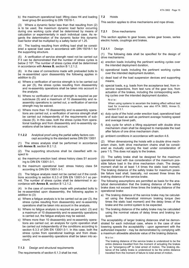
7.2 Hoists
This section applies to drive mechanisms and rope drives.
7.2.1 Drive mechanisms
This section applies to gear boxes, series gear boxes, series electric hoists, couplings and brakes.
7.2.1.1 Design
(1) The following data shall be specified for the design of drive mechanisms:
a) erection loads including the pertinent working cycles over the intended deployment duration,
b) operational loads including the pertinent working cycles over the intended deployment duration,
c) dead load of the load suspension devices and supporting means,
d) special loads, e.g. loads from the acceptance test, from in-service inspections, from test runs of the gear box, from actuation of the brakes, including the corresponding work-ing cycles over the intended deployment duration,
N o t e :
When using systems to ascertain the braking effect without test load for in-service inspection, see also KTA 3903, Annex D, section D 3.1.
e) duty cycle of the hoist under erection load, operational load and dead load as well as pertinent average hoisting speed and average travel path,
f) duty cycle for which a lifting equipment with double drive mechanism chain shall be designed to manipulate the load after failure of one drive mechanism chain.
g) ambient conditions in accordance with section 4.6.
(2) When dimensioning the hoists with a double drive mech-anism chain, both drive mechanism chains shall be consid-ered as mutually carrying the load under consideration of para 1 f). This does not apply to the brakes.
(3) The safety brake shall be designed for the maximum operational load with due consideration of the maximum pos-sible failure load in the drive mechanism chain. The design moment shall be at least 1.4 times the static load moment. The braking distance of the safety brake for maximum possi-ble failure load shall, basically, not exceed three times the braking distance of the service brake.
The following assumptions are permitted as basis for the ana-lytical demonstration that the braking distance of the safety brake does not exceed three times the braking distance of the operational brake:
a) The braking distance of the service brake may be calculat-ed using the theoretical minimum braking torque (two times the static load moment) and the delay times of the brake and the control system to be expected.
b) The braking distance of the safety brake may be calculated using the nominal values of delay times and braking tor-ques.
The acceptability of larger braking distances shall be demon-strated for each individual case, where in the case of slow lowering speeds the acceptability - upon agreement with the authorized inspector - may be demonstrated by complying with a maximum allowable absolute value of the braking distance.
N o t e :
The braking distance of the service brake is understood to be the entire distance travelled from the moment of actuating the brakes by an "emergency-off" to total arrest of motion. The braking dis-tance of the safety brake is understood to be the entire distance travelled from the moment of failure to total arrest of motion.

KTA 3902 Page 16
(4) The dimensioning of series-produced parts like brakes, brake discs, couplings, shall be based on the design data to be determined in accordance with the corresponding forms of KTA 3903, Annex C.
(5) The roller bearings shall be dimensioned on the basis of the calculation principles of the roller bearing manufacturer. Dynamic loads may be subjected to cubic averaging methods which shall be based on a probability of failure of 1 % to be taken with a1 = 0.21. The maximum test load shall be consid-ered to be the static (continuous) load.
7.2.1.2 Analytical proofs
The analytical proofs shall be performed in accordance with Annex B, section B 2.2.
7.2.1.3 Design and structural requirements
7.2.1.3.1 General
(1) Section 6.2.1.3.1 applies to hoists.
(2) In addition, hoists shall be equipped with a double drive mechanism chain or with a single drive mechanism chain with a safety brake.
(3) In the case of hoists with a double drive mechanism chain, redundancy is required for all mechanical parts in the load path according to sub-clause 2 (1) a), as well as for the brakes. This requirement does not apply to load hooks and the supporting structures of the top and bottom blocks.
(4) It shall be possible even during non-stationary operation to define the static condition of both drive mechanism chains.
(5) In the case of a single drive mechanism chain with safety brake, redundancy is required for the ropes and rope sheaves.
(6) The failure of a part within a double drive mechanism chain or within a single drive mechanism chain with safety brake shall initiate shutdown of the drive mechanism.
(7) If systems and auxiliary media (liquids, gases) are in-stalled to take up or dampen a load shifting pulse, this system shall be monitored (e.g. pressure, filling level). Any impermis-sible deviation shall initiate shutdown of the drive mecha-nisms.
(8) In case of hoists for handling
a) fuel elements, rod cluster control elements and core in-strumentation lances in pressurised water reactors,
b) fuel elements, control rods and fuel channels in boiling water reactors,
c) enclosures of core components
the loads arising at the load attachment points of these core components due to load shifting shall be limited.
The design shall ensure that the loads arising from load shifting do not lead to more unfavourable loadings at the load attach-ment points than those arising from the dead weight of the core component, multiplied by a load intensification factor of 4.
7.2.1.3.2 Gear boxes
Section 6.2.1.3.2 applies to the gear boxes.
7.2.1.3.3 Brakes
(1) Section 6.2.1.3.3 applies to brakes.
(2) In case of a break of the shaft or gear box, the safety brake shall engage on the rope drum or at the end of the drive mechanism chain. It shall be possible to safely set down the load by means of devices or operational measures.
7.2.2 Rope drives
This section applies to ropes, rope sheaves, rope drums, rope end terminations and the rope drum hinge connection.
7.2.2.1 Design
(1) Section 6.2.2.1 applies to the design of rope drives.
(2) In addition, the following applies: If the maximum opera-tional load is applied in consideration of the dynamic loading upon failure of a part in a rope drive, then the rope diameter shall be such that after failure of a part in one rope drive a minimum safety against failure of 2.5 with respect to the rope minimum breaking strength is demonstrated in the other load-carrying rope drive.
(3) The design forces and moments for the rope drum hinge connections shall be increased by 20 %.
7.2.2.2 Analytical proofs
The analytical proofs shall be performed in accordance with Annex B, section B 2.2.4.
7.2.2.3 Design and structural requirements
(1) Section 6.2.2.3 applies to rope drives.
(2) In addition, in case of a single drive mechanism chain with a safety brake each rope drum shall be equipped with a support bearing that is designed such that the safety brake remains effective in the case of a break in the shaft or gear box and that the load can be safely set down in the case of a failure of a drum bearing or break of the drum trunnion.
7.3 Lateral transport drives
This section applies to the wheel bearings and wheels, wheel axles and shafts.
7.3.1 Design
Section 6.3.1 applies to the design of lateral transport drives.
7.3.2 Analytical proofs
The analytical proofs shall be performed in accordance with Annex B, section B 1.3.
7.3.3 Design and structural requirements
Section 6.3.3 applies to the design and structural require-ments of lateral support drives.
7.4 Load carrying devices
This section applies to supporting means, load suspension devices and lifting accessories.
7.4.1 Supporting means
This section applies to jigs and fixtures permanently connect-ed to the lifting equipment for the purpose of attaching load suspension devices, lifting accessories, or loads (e.g. load hooks, load hook mountings, grabs, lifting beams, hangers as well as top and bottom blocks and the mountings for compen-sation pulleys and rope end terminations.
7.4.1.1 Design
(1) The load hooks shall be classified with respect to the drive mechanism groups in accordance with sub-clauses

KTA 3902 Page 17
6.4.1.1 (1) and (2), however, with respect to the operational load at least in drive mechanism group 3m.
(2) The design of supporting means as supporting structures shall be in accordance with the requirements of section 7.1.1 and the design of supporting means as machine parts in ac-cordance with section 7.2.1.1.
(3) In the case of non-redundant supporting means 1.25 times the dynamic factor shall be used in the analysis. Para. 1 applies to the load hook.
(4) If bolted connections according to DIN EN ISO 898-1 and DIN EN ISO 898-2 or DIN EN ISO 3506-1 and DIN EN ISO 3506-2 subject to additional tensional loading are used, then the required number of bolts shall be doubled or the deter-mined bolt load shall be increased by a factor of 1.5 both in the stress analysis and the fatigue analysis. These require-ments need not be met if bolts according to KTA 3903, Annex A, materials test sheet WPB 3.17 are used.
7.4.1.2 Analytical proofs
(1) The analytical proofs shall be performed in accordance with Annex B, section B 2.4.
(2) The stipulations of clauses 6.4.1.2 (2) and 6.4.1.2 (3) apply.
7.4.1.3 Design and structural requirements
The requirements of section 6.4.1.3 apply.
7.4.2 Load suspension devices
This section applies to jigs and fixtures not belonging to the lifting equipment, which can be connected to the supporting means of the lifting equipment for the purpose of attaching the load, e.g. load hooks, load hook mountings, lifting beams, hangers and grabs.
7.4.2.1 Design
(1) The design of load suspension devices as supporting structures shall be in accordance with the requirements of section 7.1.1 and the design of load suspension devices as machine parts in accordance with section 7.2.1.1.
(2) Section 7.4.1.1 applies to load hooks.
(3) In the case of non-redundant load suspension devices 1.25 times the dynamic factor shall be used in the analysis.
(4) The requirements of sub-clauses 6.4.2.1 (3) and of 7.4.1.1 (4) apply.
7.4.2.2 Analytical proofs
The requirements of section 7.4.1.2 apply.
7.4.2.3 Design and structural requirements
The requirements of section 6.4.2.3 apply.
7.4.3 Lifting accessories
The requirements of section 6.4.3 apply.
7.5 Electrical equipment
The requirements of section 6.5 shall be met. In addition to section 6.5, the following applies:
a) The loss of one outer conductor of the hoist motor or drive converter power supply shall automatically lead to an all-
phase switch-off of the hoist motor. The loss of one outer conductor shall trigger an alarm signal at the control points.
b) In the case of hoists with a single drive mechanism chain a monitoring device shall be provided to engage the safety brake in case of damage caused by break of the shaft or gear box. Where, in case of failure of this function, an event beyond the accident planning reference levels of § 104 of the Radiation Protection Ordinance is to be as-sumed and where the function is provided by means of software-based systems, monitoring of hoists with a maxi-mum operational load greater than 5 t shall be ensured by two independent and varying devices (for examples see Figures E-2 and E-4). In this case, one of the monitoring devices shall detect the break of the shaft or gear box by continuous comparison of rotational movement of the drive motor and the rope drum. The engagement of the safety brake at hoist movement shall be recorded by a meter. The non-disengaging of the safety brake shall be moni-tored.
c) The reinstatement to operation after failure of a part in one drive mechanism chain shall only be possible by means of a key switch in the electrical operation room.
d) Where, in case of failure of the safety travel limiter at the hoist gear travel end, an event beyond the accident plan-ning reference levels of § 104 of the Radiation Protection Ordinance is to be assumed and where the function is to be provided by means of software-based systems, switch-ing-off in case of excess of the allowable speed and of the safety travel limiter shall be effected by two independent and varying devices (for examples see Figures E-1, E-3 and E-4).
e) The failure of a part in a double drive mechanism chain or in a drive mechanism chain with safety brake shall lead to a shutdown of the drive mechanism and shall trigger an alarm signal at the control points.
f) If systems and auxiliary media (liquids, gases) are provid-ed to take up or dampen a load shifting pulse, this system shall be monitored (e.g. pressure, filling level). Any imper-missible deviation shall initiate arrest of motion and shall trigger an alarm signal at the control points.
g) A continuous load indicator shall be provided at the control points.
h) If for certain transports a limitation of the load in the part-load area of the maximum operational load is required, it shall be ensured in addition to the overload protection as per 6.5.2 (4) that further limit values for overload can be adjusted.
8 Requirements for refueling machines for light water reactors
8.1 Structures
This section applies to the supporting structures of cranes and trolleys.
8.1.1 Design
(1) For the application of this Safety Standard, two verifica-tion methods are permitted:
a) method using a global safety factor (σzul concept) accord-ing to DIN 15018-1
and
b) method using partial safety factors according to the stand-ard series DIN EN 13001.
(2) The simultaneous use of both methods within the entire verification process for a lifting device is allowed only if the

KTA 3902 Page 18
parts in question are clearly separated from each other and the transmittal of internal forces within the overall structure can be gathered entirely as well as the load bearing character-istics of the entire structure are ascertained correctly. Where an analytical proof regarding external events is to be carried out, clause 4.5 (5) shall be taken into account.
(3) The following data shall be specified for dimensioning the supporting structures:
a) operational loads including the pertinent working cycles over the intended deployment duration,
b) loads from external events in accordance with section 4.5,
c) ambient conditions in accordance with section 4.6.
8.1.2 Analytical proof
8.1.2.1 Analytical proof using the global safety factor con-cept according to DIN 15018-1
(1) The analytical proof shall be performed in accordance with Annex B, section B 2.1.1.
(2) The supporting structures shall be classified with respect to the maximum operational load in lifting class H4 and load-ing level group B4 in accordance with DIN 15018-1.
(3) Where a dynamic factor less than that resulting from (2) is to be used, the maximum dynamic load factor occurring during one working cycle shall be determined by means of calculation or experimentally in each individual case. As re-gards the determination of the dynamic factor this dynamic load factor shall be multiplied by a safety factor of 1.25.
(4) The loadings resulting from load shifting shall be consid-ered a special load case in accordance with DIN 15018-1 for the supporting structure.
(5) A verification of service strength need not be carried out if it can be demonstrated that the number of stress cycles is below 2·104. The number of stress cycles shall be determined in accordance with Annex B, section B 1.2.1.2.
(6) In the case of connections made with preloaded bolts to be re-assembled upon disassembly the following applies in addition to (5):
a) Where a verification of service strength is to be carried out as per (5), the stress cycles resulting from disassembly and re-assembly operations shall be taken into account in the analysis.
b) Where no verification of service strength is required as per subclause (5) and a maximum of 10 disassembly and re-assembly operations is carried out, a verification of service strength may be waived.
c) Where more than 10 disassembly and re-assembly opera-tions are carried out, a verification of service strength shall be carried out independently of the requirements of sub-clause (5). In this case, both the stress cycles from opera-tional loadings and from disassembly and re-assembly op-erations shall be taken into account.
8.1.2.2 Analytical proof using the partial safety factors concept according to the standard series DIN EN 13001
(1) The stress analysis shall be performed in accordance with Annex B, section B 2.1.2.
(2) The supporting structures shall be classified with respect to the maximum operational load: stress history class S4 ac-cording to DIN EN 13001-3-1.
(3) The fatigue analysis need not be carried out if the condi-tions according to section 6.3.3 of DIN EN 13001-3-1 so per-
mit. The number of stress cycles shall be determined in ac-cordance with Annex B, section B 1.2.1.2.
(4) In the case of connections made with preloaded bolts to be re-assembled upon disassembly, the following applies in addition to (3):
a) Where a fatigue analysis is to be carried out as per (3), the stress cycles resulting from disassembly and re-assembly operations shall be taken into account in the analysis.
b) Where no fatigue analysis is required as per subcl. (3) and a maximum of 10 disassembly and re-assembly operations is carried out, the fatigue analysis may be waived.
c) Where more than 10 disassembly and re-assembly opera-tions are carried out, an analysis for cyclic operation shall be carried out independently of the conditions according to section 6.3.3 of DIN EN 13001-3-1. In this case, both the stress cycles from operational loadings and from disassem-bly and re-assembly operations shall be taken into account.
8.1.3 Design and structural requirements
(1) The requirements of section 6.1.3 apply.
(2) The refueling machines shall be constructed such that corresponding compensation measures counteract the deflec-tion of the bridge girders in order to make vertical lifting possi-ble during insertion and removal of fuel assemblies.
8.2 Hoists
This section applies to drive mechanisms and rope drives.
8.2.1 Drive mechanisms
This section applies to gear boxes, series gear boxes, cou-plings and brakes.
8.2.1.1 Design
(1) The following data shall be specified for the design of drive mechanisms:
a) operational loads including the pertinent working cycles over the intended deployment duration,
b) dead load of the load carrying device,
c) special loads, e.g. loads from the acceptance test, from in-service inspections, from test runs of the transmission, from actuation of the brakes, including the corresponding working cycles over the intended deployment duration,
N o t e :
When using systems to ascertain the braking effect without test load for in-service inspection, see also KTA 3903, Annex D, section D 3.1.
d) duty cycle of the hoist under operational load and dead load as well as pertinent average hoisting speed and aver-age travel paths,
e) duty cycle for which a lifting equipment with double drive mechanism chain shall be designed to manipulate the load after failure of one drive mechanism chains.
f) ambient conditions in accordance with section 4.6.
(2) When dimensioning the hoists with a double drive mech-anism chain, both drive mechanism chains shall be consid-ered as mutually carrying the load under consideration of para. (1) e). This does not apply to the brakes.
(3) The safety brake shall be designed for the maximum operational load with due consideration of the maximum pos-sible failure load in the drive mechanism chain. The design moment shall be at least 1.4 times the static load moment. The braking distance of the safety brake for maximum possi-

KTA 3902 Page 19
ble failure load shall basically not exceed three times the brak-ing distance of the service brake.
The following assumptions are permitted as basis for the ana-lytical demonstration that the braking distance of the safety brake does not exceed three times the braking distance of the service brake:
a) The braking distance of the service brake may be calculat-ed using the theoretical minimum braking torque (two times the static load moment) and the delay times of the brake and the control system to be expected.
b) The braking distance of the safety brake may be calculated using the nominal values of delay times and braking tor-ques.
The acceptability of larger braking distances shall be demon-strated for each individual case, where in the case of slow lowering speeds the acceptability - upon agreement with the authorized inspector - may be demonstrated by complying with a maximum allowable absolute value of the braking distance.
N o t e : The braking distance of the service brake is understood to be the entire distance travelled from the moment of actuating the brakes by an "emergency-off" to total arrest of motion. The braking dis-tance of the safety brake is understood to be the entire distance travelled from the moment of failure to total arrest of motion.
(4) The dimensioning of series-produced parts like brakes, brake discs, couplings, shall be based on the design data to be determined in accordance with the corresponding forms of KTA 3903, Annex C.
(5) The roller bearings shall be dimensioned on the basis of the calculation principles of the roller bearing manufacturer. Dynamic loads may be subjected to cubic averaging methods which shall be based on a probability of failure of 1 % to be taken with a1 = 0.21. The maximum test load shall be consid-ered to be the static (continuous) load.
8.2.1.2 Analytical proofs
The analytical proofs shall be performed in accordance with Annex B, section B 2.2.
8.2.1.3 Design and structural requirements
8.2.1.3.1 General
(1) Section 6.2.1.3 applies to hoists.
(2) In addition, hoists shall be equipped with a double drive mechanism chain or with a single drive mechanism chain with a safety brake.
(3) In the case of hoists with a double drive mechanism chain, redundancy is required for all mechanical parts in the load path according to sub-clause 2 (1) a), as well as for the brakes. This requirement does not apply to grabs and their load guides.
(4) It shall be possible even during non-stationary operation to define the static condition of both drive mechanism chains.
(5) In the case of a single drive mechanism chain with safety brake, redundancy is required for the ropes and rope sheaves.
(6) The failure of a part within a double drive mechanism chain or within a single drive mechanism chain with safety brake shall initiate shutdown of the drive mechanism.
(7) Slack rope monitoring shall be carried out and equipment for a continuous measurement of the load be provided.
(8) It must be possible to set down the fuel assembly in a safe position, even in the case of power failure or failure of a part in the drive mechanism.
(9) The movements of all manually operated parts, with the exception of the emergency drives, shall be limited in a relia-ble way.
(10) If systems and auxiliary media (liquids, gases) are in-stalled to take up or dampen a load shifting pulse, this system shall be monitored (e.g. pressure, filling level). Any impermis-sible deviation shall initiate arrest of motion.
(11) In case of hoists for handling
a) fuel elements, rod cluster control elements and core in-strumentation lances in pressurised water reactors,
b) fuel elements, control rods and fuel channels in boiling water reactors,
c) enclosures of core components
the loads arising at the load attachment points of these core components due to load shifting shall be limited.
The design shall ensure that the loads arising from load shift-ing do not lead to more unfavourable loadings at the load attachment points than those arising from the dead weight of the core component, multiplied by a load intensification factor of 4.
8.2.1.3.2 Gear boxes
Section 6.2.1.3.2 applies to the gear boxes.
8.2.1.3.3 Brakes
(1) Section 6.2.1.3.3 applies to brakes.
(2) In the case of a break of the shaft or gear box, the safety brake shall engage on the rope drum or at the end of the drive mechanism chain. It shall be possible to safely set down the load by means of devices or operational measures.
8.2.2 Rope drives
This section applies to ropes, rope sheaves, rope drums, rope end terminations and the rope drum hinge connection.
8.2.2.1 Design
(1) Section 6.2.2.1 applies to the design of rope drives.
(2) In addition to section 6.2.2.1, if the maximum operational load is applied in consideration of the dynamic loading upon failure of a part in a rope drive, then the rope diameter shall be such that after failure of a part in one rope drive a minimum safety against failure of 2.5 with respect to the rope minimum breaking strength is demonstrated in the other load-carrying rope drive.
(3) The design forces and moments for the rope drum hinge connections shall be increased by 20 %.
8.2.2.2 Analytical proofs
The analytical proofs shall be performed in accordance with Annex B, section B 2.2.4.
8.2.2.3 Design and structural requirements
(1) Section 6.2.2.3 applies to rope drives.
(2) In addition, each rope drum shall be equipped with a support bearing that is designed such that the safety brake remains effective in the case of a break in the shaft or gear box or that the load can be safely set down in the case of a failure of a drum bearing or break of the drum trunnion.

KTA 3902 Page 20
8.3 Lateral transport drives
This section applies to the wheel bearings and wheels, wheel axles and shafts.
8.3.1 Design
Section 6.3.1 applies to the design of lateral transport drives.
8.3.2 Analytical proofs
The analytical proofs shall be performed in accordance with Annex B, section B 1.3.
8.3.3 Design and structural requirements
Section 6.3.3 applies to the design and structural require-ments of lateral support drives.
8.4 Load carrying devices
This section applies to grabs and load guides of refueling machines, e.g. telescoping mast and guide tube.
8.4.1 Design
(1) The design of load guides as supporting structures shall be in accordance with the requirements of section 8.1 and the design of grabs in accordance with section 8.2.
(2) For non-redundant parts 1.25 times the dynamic factor shall used in the analysis.
(3) If bolted connections according to DIN EN ISO 898-1 and DIN EN ISO 898-2 or DIN EN ISO 3506-1 and DIN EN ISO 3506-2 subject to additional tensional loading are used, then the required number of bolts shall be doubled or the deter-mined bolt load shall be increased by a factor of 1.5 both in the stress analysis and the fatigue analysis. These require-ments need not be met if bolts according to KTA 3903, Annex A, materials test sheet WPB 3.17 are used.
8.4.2 Analytical proofs
(1) The analytical proofs shall be performed in accordance with Annex B, section B 2.4.
(2) The stipulations of clauses 6.4.1.2 (2) apply.
8.4.3 Design and structural requirements
(1) The load shall be attached in a positive-locking way only.
(2) The grabs shall be interlocked in two independent ways against unintentional opening and opening in locations that are non-permissible for safety reasons. This also applies in the case of complete or partial power failure (electricity, hy-draulics, pneumatics).
(3) It must be possible to set down the fuel assembly in a safe position, even in the case of a power failure.
8.5 Electrical equipment
The requirements of sections 6.5 and 7.5 shall be met, how-ever, the realization of the safety functions as per sub-clause 7.5 b) or 7.5 d) is not required by means of two different sys-tems. In addition to the requirements of sections 6.5 and 7.5, the following applies:
a) The end positions "open" and "closed" of the grabs and all related interlocks shall be optically displayed at the control points. No movement of the hoist shall be possible before any of the two end positions is reached.
b) It shall not be possible to actuate the switch for the power supply to the refueling machine unless this actuation has been released, either by means of a key-operated switch or similarly safe switching means from the reactor control room or from a location comparable from a safety point of view. Communication shall be possible between this loca-tion and all control points, either directly or through an in-tercommunication system connected to a continuous power supply. The action of taking back the clearance may not trigger turning-off of the power supply switch; it shall, how-ever, prevent a reactivation of the power supply switch af-ter it has been turned off.
c) The position of the fuel assembly grabs shall be displayed with all coordinates.
d) The continuous load measurement device on the control console shall be equipped with a display of the actual load attached to the rope. For certain assigned loads, e.g. fuel assemblies or control rods, specifically assigned limit val-ues depending on the type of operation shall automatically be activated in the case of overload or underload and switch off the hoist.
e) The response of any limit load monitor and the response of the slack-rope monitor shall trigger an alarm signal at the control points.
f) Lateral movements shall be interlocked such that they are only possible if the grab has reached the allowable altitude permitted for the respective operation.
g) In order to limit the lateral movements to the travel area per-mitted with regard to safety which is defined by the contour of the reactor and fuel pool areas as well as by fixed inter-nals, an independent safety travel limiter shall be provided in addition to the operational travel limiter according to clause 6.5.3 (1).
h) If parts of the refueling machine can be moved both manu-ally and by motors, turning on of the motor drive is not al-lowed and shall be made impossible as long as a manual movement can be performed.
i) In the case of hoists with telescope mast the correct se-quence of mast sections during extension and retraction of the telescope mast shall be monitored. In the case of hoists with double grab the correct sequence during exten-sion and retraction of the movable parts (centring bell, fuel assembly grabs, control rod grabs) shall be monitored.
In case of failure the hoist shall be switched off.
j) The setting down of a transported load (e.g. fuel element) on an already occupied position in the fuel pool or reactor core shall be prevented by an interlock.
k) The electrical interlock according to clause 6.5.2 (10) shall be designed such that the control command for the de-tachment of the load can only be executed at simultaneous release of two independent criteria (e.g. hoisting height and load).
l) It shall be ensured by interlocking that, when passing over the BWR flooding compensator or the PWR reactor vessel cavity seal, no lifting or lowering movement of the main hoist is possible.

KTA 3902 Page 21
Annex A
Examples for classification of lifting equipment
A 1 Examples for classification of lifting equipment in
Pressurized Water Reactor plants
Serial number
Lifting equipment
Additional require-ments in
accordance with
section 4.2
Increased require-ments in
accordance with
section 4.3
1 Reactor building crane except for maintenance hoist
X
2 Semi-gantry crane X
3 Walking crane inside the reactor building X
4 Crane in new fuel stor-age X
5 Auxiliary hoist on the refueling machine
X
6 Lifting beam for radiation protection slabs above the reactor pool and set-down pool
X
7 Lifting beam for the cov-er of the reactor pressure vessel
X
8 Lifting beam for the irra-diated fuel shipping cask
X
9 Lifting beam for the ship-ping cask for fresh UO2 fuel assemblies
X
10 Lifting beam for the me-tallic contamination pro-tection shroud
X
11 Lifting beam for reactor pressure vessel inter-nals:
- upper core structure X
- lower core structure X
12 Lifting beam for refueling slot gates
X
13 Lifting beam for the stud tensioner of the reactor pressure vessel cover
X
A2 Examples for classification of lifting equipment in Boiling Water Reactor plants
Serial number
Lifting equipment
Additional require-ments in
accordance with
section 4.2
Increased require-ments in
accordance with
section 4.3
1 Reactor building crane except for maintenance hoist
X
2 Crane in new fuel storage X
3 Auxiliary hoist on the refueling machine
X
4 Winch for handling irra-diated fuel assemblies in the storage pool
X
5 Lifting beam for the cov-er of the reactor pressure vessel and containment and for the flooding compensator
X
6 Lifting beam for radiation protection slabs of the reactor pool and set-down pool
X
7 Lifting beam for refueling slot gates
X
8 Lifting beam for steam separator and steam dryer
X
9 Lifting beam for the irra-diated fuel shipping cask inside the reactor building
X
10 Lifting beam for the ship-ping cask for fresh UO2 fuel assemblies inside the reactor building
X
11 Lifting beam for the me-tallic contamination pro-tection shroud
X
12 Lifting beam for the stud tensioner of the reactor pressure vessel cover
X
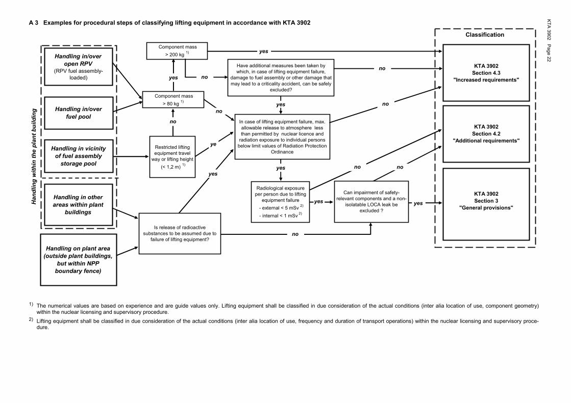
KT
A 3
902
Pa
ge
22
A 3 Examples for procedural steps of classifying lifting equipment in accordance with KTA 3902
yes
no
yes
no
no
Have additional measures been taken by which, in case of lifting equipment failure,
damage to fuel assembly or other damage that may lead to a criticality accident, can be safely
excluded?
no
Restricted lifting equipment travel
way or lifting height
(< 1,2 m) 1)
Component mass
> 200 kg 1)
Component mass
> 80 kg 1)
Classification
no
Can impairment of safety-relevant components and a non-
isolatable LOCA leak be excluded ?
yes no
yesHa
nd
lin
g w
ith
in t
he
pla
nt
bu
ild
ing
no
In case of lifting equipment failure, max. allowable release to atmosphere less than permitted by nuclear licence and
radiation exposure to individual persons below limit values of Radiation Protection
Ordinance
Is release of radioactive substances to be assumed due to
failure of lifting equipment?
KTA 3902
Section 4.3
"Increased requirements"
KTA 3902
Section 4.2
"Additional requirements"
KTA 3902
Section 3
"General provisions"
Handling in/over
open RPV
(RPV fuel assembly-loaded)
Handling in/over
fuel pool
Handling in vicinity
of fuel assembly
storage pool
Handling in other
areas within plant
buildings
Handling on plant area
(outside plant buildings,
but within NPP
boundary fence)
yes
ye
s
yes
yes
no
Radiological exposure per person due to lifting
equipment failure
- external < 5 mSv 2)
- internal < 1 mSv 2)
1) The numerical values are based on experience and are guide values only. Lifting equipment shall be classified in due consideration of the actual conditions (inter alia location of use, component geometry) within the nuclear licensing and supervisory procedure.
2) Lifting equipment shall be classified in due consideration of the actual conditions (inter alia location of use, frequency and duration of transport operations) within the nuclear licensing and supervisory proce-dure.

KTA 3902 Page 23
Annex B
Load cases and analytical proofs for lifting equipment
B 1 Load cases and analytical proofs for cranes, winches, trolleys as well as load carrying devices under section 6 ...................................................................................................................................... 23
B 1.1 Structures .............................................................................................................................................. 23
B 1.2 Hoists ..................................................................................................................................................... 24
B 1.3 Lateral transport drives .......................................................................................................................... 28
B 1.4 Load carrying devices ............................................................................................................................ 31
B 2 Load cases and analytical proofs for cranes, winches, trolleys as well as load carrying devices under section 7 and for refueling machines under section 8 .................................................................. 32
B 2.1 Structures .............................................................................................................................................. 32
B 2.2 Hoists ..................................................................................................................................................... 33
B 2.3 Lateral transport drives .......................................................................................................................... 38
B 2.4 Load carrying devices ............................................................................................................................ 38
B 3 Analytical proof using the finite element method.................................................................................... 38
B 3.1 General .................................................................................................................................................. 38
B 3.2 Stress analysis for structures using the global safety factor concept in proofs according to DIN 15018-1 and for non-rotating machine parts ................................................................................... 38
B 3.3 Stress analysis for structures using the partial safety factors concept according to DIN EN 13001-3-1 ................................................................................................................................. 39
B 4 Nomenclature and physical quantities ................................................................................................... 40
B 1 Load cases and analytical proofs for cranes, winch-
es, trolleys as well as load carrying devices under section 6
B 1.1 Structures
B 1.1.1 Analytical proof using the global safety factor concept according to DIN 15018-1
(1) The erection and operational load cases shall be calcu-lated in accordance with DIN 15018-1. For structural mem-bers made of the austenitic steels 1.4541, 1.4306 and 1.4571 according to DIN EN 10088-2 or DIN EN 10088-3 the allowable stresses shall be taken from section D 1.
(2) The verification procedure according to section 4.3 of KTA 3205.1 shall be used for all external events.
(3) Where the operating conditions are exactly known, e.g. the actually occurring loadings and stress cycles, the verifica-tion of service strength may be performed for a single-step or multi-step load collective on the basis of a stress-number diagram according to Annex C for the steels S235 and S355, or on the basis of a stress-number diagram according to sec-tion D 2 for the austenitic steels 1.4541, 1.4306 and 1.4571.
N o t e :
The relationship between number of stress cycles and number of working cycles can be derived from section B 1.2.1.2.
The analytical proof based on a multi-step stress-number diagram shall be performed in due consideration of a damage-equivalent stress to the linear damage rule (Miner rule) ac-cording to formula (B 1-14).
The following safety factor as regards the allowable maximum stress shall be observed:
σσ=ν /D ≥ 1.12. (B 1-1)
B 1.1.2 Analytical proof using the partial safety factors con-cept
(1) The erection and operational load cases shall be calcu-lated in accordance with DIN EN 13001-3-1 in conjunction with DIN EN 13001-1 and DIN EN 13001-2 using the specifications given in (2).
A design of structural members using austenitic steels within the partial safety factors concept is permitted only in those cases where the fatigue analysis may be waived according to section 6.3.3 of DIN EN 13001-3-1, in which case the number of stress cycles shall be determined according to section B 1.2.1.2.
(2) The procedure of proof according to DIN EN 13001-3-1 in conjunction with DIN EN 13001-1 and DIN EN 13001-2 shall be conducted in compliance with the following requirements:
a) Regardless of the specific conditions of crane design and operation, the dynamic factor Φ2 used in the proof accord-ing to DIN 13001-2 shall be calculated by applying the fol-lowing formulae:
aa) for operational loads: Φ2 = 1.3 + 0.396 ⋅ vh,max
ab) for erection loads: Φ2 = 1.1 + 0.132 ⋅ vh,max
For vh,max the maximum hoisting speed relevant for the load case in question shall be inserted.
b) Where a dynamic factor less than that resulting from a) is to be used, the maximum dynamic load factor occurring during one working cycle shall be determined by means of calculation or experimentally in each individual case. For the determination of the dynamic factor this dynamic load factor shall be multiplied by a safety factor of 1.12.
c) When calculating the loads due to skewed running, the coefficient of friction for cleaned rails shall be used:
µ0 = 0.3.

KTA 3902 Page 24
d) Where a verification of loads due to wind during crane operation is required, the wind loads shall be calculated using the wind state “normal”.
e) It shall be ensured that during a buffer impact no negative wheel loads can occur due to a presumed load resulting from 1.1 times the buffer force, the forces due to driven masses of dead loads and the lifting load, if any.
f) The specific resistance factor for material γsm shall be used as specified in section 5.2.2 of DIN EN 13001-3-1, howev-er, a value of at least 1.0 shall be applied.
g) When determining the limit design stresses of bolted con-nections loaded in tension, a load introduction factor of αL = 1 shall be used. The specific resistance factor of slip-resistance connections γss shall be selected as specified in Table 6 of DIN EN 13001-3-1 assuming that a hazard is created in the case of connection slippage.
h) The test loads shall be as follows:
ha) for cranes, winches, trolleys, load suspending devices and refueling machines as specified in KTA 3903 Ta-ble 8-1 ser. no. 1.4,
hb) for load suspension devices and lifting accessories as specified in KTA 3903 Table 8-1 ser. no. 2.4.
The proof shall be performed in accordance with the re-quirements in section 4.2.4.3 of DIN EN 13001-2 using the test loads as specified under ha) and hb) and the dynamic factor as specified under a).
i) The fatigue strength specific resistance factor γmf in the fatigue analysis according to DIN EN 13001-3-1 shall be taken as γmf = 1.25 for parts and welded connections as well as for bolted connections which are not hot dip galvanised, and as γmf = 1.5 for hot dip galvanised bolted connections.
j) Based on the specifications as per a) through i), the risk coefficient γn according to DIN EN 13001-2 may be taken as 1.0.
(3) The following procedures shall be used to demonstrate the safety against all external events:
a) either the procedure according to DIN EN 13001-3-1 using the following resistance and partial safety factors
γm = 1.0
γP = 1.0
where in the case of parts and welded connections made of austenitic steels the Rp1.0 proof stress may be used as fy instead of the Rp0.2 proof stress,
or
b) the procedure according to section 4.2 of KTA 3205.1.
(4) Where the operating conditions are exactly known, e.g. the actually occurring loadings and stress cycles, the fatigue analysis may be performed for a single-step or multi-step load collective in accordance with the requirements of DIN EN 13001-3-1 and the specifications in (2).
N o t e :
The relationship between the number of stress cycles and the number of working cycles can be derived from section B 1.2.1.2.
The analytical proof based on a multi-step stress-number diagram shall be performed in due consideration of a damage-equivalent stress to the linear damage rule (Miner rule) ac-cording to formula (B 1-14).
The following safety factor as regards the allowable stress range shall be observed:
12.1Sd
Rd ≥σ∆
σ∆=ν . (B 1-2)
B 1.1.3 Alternative ways of analytical proof
(1) Analytical proofs may be performed either by calculation or experimentally or as a combination of calculation and ex-periments.
(2) The stress analysis or fatigue analysis may be performed by calculation using the Finite Element Method in compliance with the requirements specified in section B 3, e.g. because the complexity of a structural member so requires.
(3) If types of analytical proof are used, which differ from the approach according to DIN 15018-1 and the standard series DIN EN 13001, it shall be ensured that the safety level is not lower than required by these standards.
B 1.2 Hoists
B 1.2.1 Design parameters
B 1.2.1.1 Determination of moments and forces
(1) The moments specified in Table B 1-1 shall be deter-mined for the design of parts of the drive mechanism chain, starting with the service brake and ending with the rope drum.
N o t e :
When using systems to ascertain the braking effect without test load for in-service inspection, see also KTA 3903, Annex D, sec-tion D 3.1.
(2) The calculation of the moments $TM , $TB , 0T̂ and $TSO shall
be based on the following operational conditions and shall be
performed for the individual intersection:
a) Acceleration during lifting:
( )$T T T T T T TJ
J JBS L R s R Mot L Rab
ab an= − + ⋅ ⋅ + − − ⋅
+
ϕ 2
(B 1-3)
where TMot is the largest motor moment created during the stepwise switching-up of the motor for drives with three-phase current slip-ring rotor motors. If this is not exactly known, then, in case of automatic switching-up with time or frequency relays, a value of 2/3 of the motor breakdown torque, and in case of manual switching-up the full motor breakdown torque shall be used. In the case of drives with squirrel-cage rotor motors, the start-up moment upon turn-ing on the motor shall be used. In the case of converter drives, the motor moment at the upper current limit shall be used.
b) Deceleration during lowering:
( )$T T T T T TJ
J JBR L R s Bre L Rab
ab an= + + ⋅ − − ⋅
+ϕ , (B 1-4)
with ϕs = 2
c) Lifting of a set-down load:
( ) ψ⋅+= RLAN TTT̂ (B 1-5)
N o t e :
The dynamic factor ψ is chosen in accordance with the classifi-cation of the supporting structure.
The following rule shall apply to the directional sense:
All torques shall be given a positive sign if, on the input side of the drive shaft analysed, they act in the direction of motion and, on the output side in the direction of motion of the drive shaft counter to the direction of motion.
(3) The design forces for the non-rotating mechanical parts between rope drum and load shall be determined from the above moments.

KTA 3902 Page 25
Load case no.
Mo-ments
Nomenclature Type of proof
1 TM
$TM
Static moment for the maxi-mum erection load
Dynamic moment for the maximum erection load TM (largest value of $TBS , $TBR , $TAN )
Fatigue analysis and static stress analysis for the first step of the load collective
2 TB $TB
Static moment for the maxi-mum operational load
Dynamic moment for the maximum operational load TB (largest value of $TBS , $TBR , $TAN )
3 T0
0T̂
Static moment for idling runs if the dead weight of half the supporting means plus load suspension device plus lifting accessory is larger than 30 % of the maximum load
Dynamic moment for dead weight TO (largest value of $TBS , $TBR , $TAN )
4 TSO
$TSO
Maximum moment for the spe-cial load case, e.g. acceptance test, in-service inspection, gear box test run, simultane-ous engagement of the service and auxiliary brake
Dynamic moment for the special load case TSO
Table B 1-1: Moments
B 1.2.1.2 Determination of stress cycles
(1) The stress cycles required for the fatigue analysis shall be determined as follows:
a) rotating parts:
ii
ii s
v3600
Uh ⋅
⋅= (B 1-6)
ii
ii t̂60
nUN̂ ⋅⋅=σ (B 1-7)
$N U Zi i Schiτ ε= ⋅ ⋅ (B 1-8)
σσ −⋅⋅= iiii N̂hn60N (B 1-9)
Niτ = 0, because only static stresses occur. (B 1-10)
b) non-rotating parts:
aSchii kZUN̂i
⋅⋅=σ (B 1-11)
σiN = 0, because only static stresses occur. (B 1-10)
The following values shall be inserted:
ε = 10
ka = 3
it̂ = 30 s however, at a maximum only 50 % of the inte-gral running time if no additional proof is ren-dered,
ZSchi = 10 in the case of precision hoists and of
converter drives,
ZSchi = 20 in the case of other drives.
(2) If the actual stresses within one working cycle are known through experimental investigations or through an applicable estimation of the loading with adequate mathematical models (e.g. taking into account the inner-friction loss of the oscillatory energy impressed upon the system by the coupling impulse), the fatigue analysis may be based on these values.
B 1.2.1.3 Determination of the (general) load collective
(1) From the determined moments in accordance with Ta-ble B 1-1 and the resulting forces, the stresses in the part shall be calculated and sorted according to size. With the corresponding stress cycles, the load collective shall be estab-lished. This load collective shall be compared to the part's stress-number diagram (cf. Figure B 1-1).
Examples for determining load collectives are presented in [12].
σ
σ
σσ
γ
σ
σ
σ
4
D
D
34
3
Z
2
21
1
x
NN
c
1log (N)N
log ( )
N
N
N
Figure B 1-1: Stress collectives
(2) The location of the part's S/N diagram within the finite-life fatigue range shall be determined from the values for NZ and σx as well as ND and σD; in a logarithmic diagram, the S/N diagram is represented by a straight line with a gradient that shall be determined by the following equation:
c = tan γ = Dx
ZD
loglog
NlogNlog
σ−σ
− (B 1-13)
(3) The fatigue analysis shall be based on cases A, B or C shown in Figures B 1-2 through B 1-4:
a) Case A: σ1 ≥ σD
If no step in the load collective does touch or exceed the ex-tended finite-life fatigue line, then σ shall be calculated from all steps in the load collective.
b) Case B: σ1 < σD
N1 < ND
None of the stress cycle values larger than ND shall be consid-ered. σ shall be calculated from the load collective steps up to ND.
c) Case C: σ1 < σD
N1 ≥ ND
The endurance limit shall be calculated on the basis of σ1.
(4) In Case A and Case B, a damaging equivalent stress (e.g. σ, k, τ ) shall be calculated in accordance with the linear damage rule (Miner's rule) as follows:
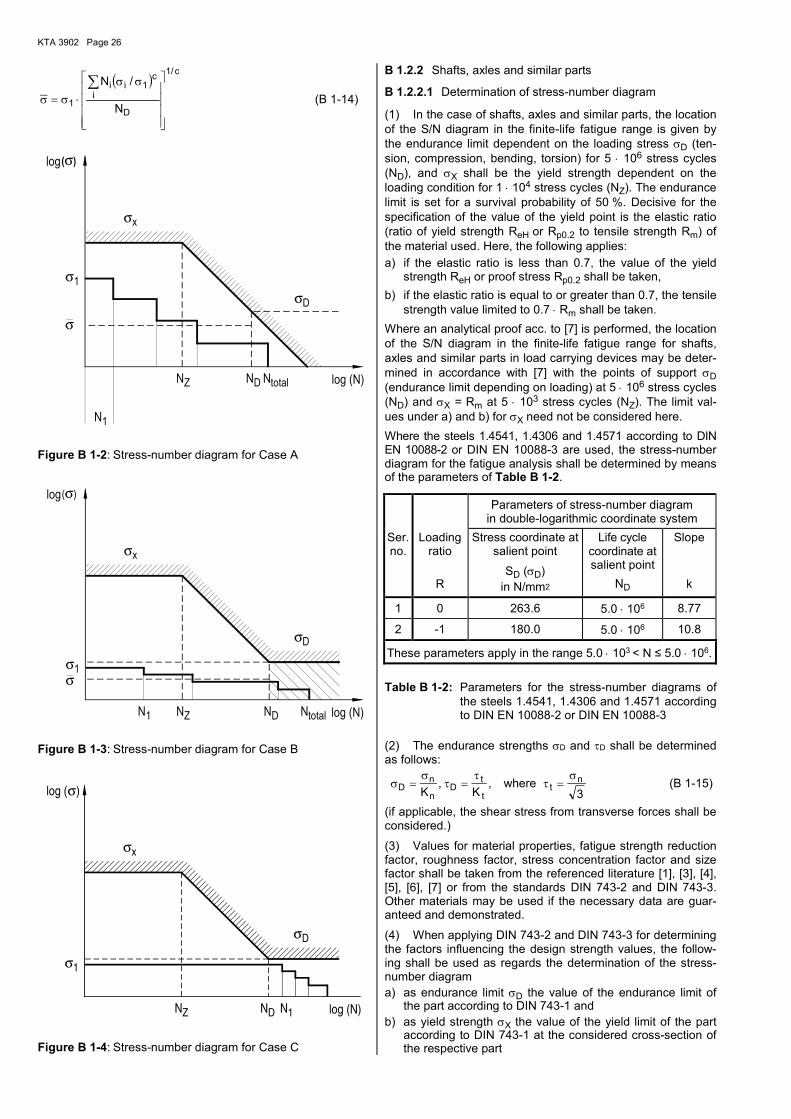
KTA 3902 Page 26
( )c/1
D
i
c1ii
1 N
/N
σσ
⋅σ=σ∑
(B 1-14)
σ
σ
( )σ
σ
σ
totalZ
1
D
D
x
1
N N log (N)
N
N
log
Figure B 1-2: Stress-number diagram for Case A
σ
σ
σ
σ
( )σ
1 DZ total
x
D
1
NN log (N)N N
log
Figure B 1-3: Stress-number diagram for Case B
σ
σ
σ
σ
Z 1
1
D
D
x
N
log ( )
N N log (N)
Figure B 1-4: Stress-number diagram for Case C
B 1.2.2 Shafts, axles and similar parts
B 1.2.2.1 Determination of stress-number diagram
(1) In the case of shafts, axles and similar parts, the location of the S/N diagram in the finite-life fatigue range is given by the endurance limit dependent on the loading stress σD (ten-sion, compression, bending, torsion) for 5 ⋅ 106 stress cycles (ND), and σX shall be the yield strength dependent on the loading condition for 1 ⋅ 104 stress cycles (NZ). The endurance limit is set for a survival probability of 50 %. Decisive for the specification of the value of the yield point is the elastic ratio (ratio of yield strength ReH or Rp0.2 to tensile strength Rm) of the material used. Here, the following applies:
a) if the elastic ratio is less than 0.7, the value of the yield strength ReH or proof stress Rp0.2 shall be taken,
b) if the elastic ratio is equal to or greater than 0.7, the tensile strength value limited to 0.7 ⋅ Rm shall be taken.
Where an analytical proof acc. to [7] is performed, the location of the S/N diagram in the finite-life fatigue range for shafts, axles and similar parts in load carrying devices may be deter-mined in accordance with [7] with the points of support σD
(endurance limit depending on loading) at 5 ⋅ 106 stress cycles (ND) and σX = Rm at 5 ⋅ 103 stress cycles (NZ). The limit val-ues under a) and b) for σX need not be considered here.
Where the steels 1.4541, 1.4306 and 1.4571 according to DIN EN 10088-2 or DIN EN 10088-3 are used, the stress-number diagram for the fatigue analysis shall be determined by means of the parameters of Table B 1-2.
Parameters of stress-number diagram in double-logarithmic coordinate system
Ser. no.
Loading ratio
R
Stress coordinate at salient point
SD (σD) in N/mm2
Life cycle coordinate at salient point
ND
Slope
k
1 0 263.6 5.0 ⋅ 106 8.77
2 -1 180.0 5.0 ⋅ 106 10.8
These parameters apply in the range 5.0 ⋅ 103 < N ≤ 5.0 ⋅ 106.
Table B 1-2: Parameters for the stress-number diagrams of the steels 1.4541, 1.4306 and 1.4571 according to DIN EN 10088-2 or DIN EN 10088-3
(2) The endurance strengths σD and τD shall be determined as follows:
σσ
ττ
τσ
Dn
nD
t
tt
n
K Kwhere= = =, ,
3 (B 1-15)
(if applicable, the shear stress from transverse forces shall be considered.)
(3) Values for material properties, fatigue strength reduction factor, roughness factor, stress concentration factor and size factor shall be taken from the referenced literature [1], [3], [4], [5], [6], [7] or from the standards DIN 743-2 and DIN 743-3. Other materials may be used if the necessary data are guar-anteed and demonstrated.
(4) When applying DIN 743-2 and DIN 743-3 for determining the factors influencing the design strength values, the follow-ing shall be used as regards the determination of the stress-number diagram a) as endurance limit σD the value of the endurance limit of
the part according to DIN 743-1 and b) as yield strength σX the value of the yield limit of the part
according to DIN 743-1 at the considered cross-section of the respective part

KTA 3902 Page 27
in dependence of the actually occurring loading (tension/pres-sure, bending or torsion) and the stress history (cyclic loading, pulsating loading) to meet the requirements of DIN 743-1, DIN 743-2 and DIN 743-3. In this case, the ratio of mean stress to stress amplitude due to the individually acting external load can be presumed to be constant for all steps of the load col-lective. The limit values fixed under (1) (a) and (1) (b) for the yield strength of the respective material in dependence of the elastic ratio shall be considered.
B 1.2.2.2 Safety factors for shafts, axles and similar parts
(1) The safety factors specified in Table B 1-3 shall apply.
(2) When applying the Finite Element Method the require-ments of section B3 shall be met.
Proof of Loading
type Equation
for proof of safety
Required safety factor for additional requirements under sec. 6
Static strength 1)
First step of the collective
( )ν σ σ ασ1 1= ⋅x kn/ ≥ 1.25
( )ν τ τ ατ1 1= ⋅St k t/ ≥ 1.25
Cyclic strength
Collec-tive Case A or B
ν σ σσ = D / ≥ 2.0
ν τ ττ = D / ≥ 2.0
σ
σ
τ
τ νn
D
t
D
+
≤
2 2 210.
≥ 2.0
Endurance strength
First collective step Case A
ν σ σσ = D / 1 ≥ 2.0
ν τ ττ = D / 1 ≥ 2.0
σ
σ
τ
τ ν1
21
2 210
D D
+
≤
. ≥ 2.0
1) Applies only to hoists; in the case of non-rotating parts no stress concentration factors are required and the required safety factor is greater than or equal to 1.5, where ReH or Rp0.2 shall be taken for σx.
Table B 1-3: Safety factors for shafts, axles and similar parts
B 1.2.2.3 Proofs regarding fitting keys
(1) The allowable contact Hertzian stress in the case of one parallel key for the linkage with shaft or hub may be
pzul = 0.4 ⋅ Rp0.2 (ReH) (B 1-16)
and, with two parallel keys,
pzul = 0.3 ⋅ Rp0.2 (ReH) (B 1-17)
(2) The allowable contact Hertzian stress in the case of a hardened parallel key linkage may be
pzul = 0.5 ⋅ Rp0.2 (ReH) (B 1-18)
and, with two parallel keys,
pzul = 0.4 ⋅ Rp0.2 (ReH) (B 1-19)
(3) The allowable contact Hertzian stresses apply to loadings from operational or erection loads with static moment. For the special loading case, these values may be increased by 50 %.
(4) Proofs for splined shafts and pinion shaft linkages shall be performed in accordance with Decker [4], where the allow-able contact Hertzian stress of pzul = 0.4 · Rp0.2 (ReH) shall not be exceeded.
B 1.2.3 Pinions
B 1.2.3.1 Determination of the effective stresses and of the load capacity
(1) The pinions’ strength shall be determined in accordance with the following requirements according to DIN 3990-11 or the analysis procedure of Niemann [2].
(2) For both calculation procedures the stress levels for the pinions (tooth foot stress and tooth flank compression) shall be determined from the torque levels and be correlated with the corresponding load cycle values.
(3) According to the calculation procedure of DIN 3990-11 the effective tooth foot stress σF and the flank compression σH shall be determined for each stress level if they are required for the fatigue analysis with regard to the cases mentioned in B 1.2.1.3.
(4) If the analysis procedure of Niemann [2] is used for de-termining the strength of pinions, the following shall apply:
For each stress level the effective tooth foot stress σW and the effective tooth flank compression kW shall be determined in accordance with Niemann [2] for the pinions, taking into con-sideration the following additional requirements for the tooth bearing error coefficient CT provided, this is necessary with regard to the fatigue analysis of the case differentiation men-tioned in B 1.2.1.3.
a) For tempered and gas-nitrided pinions, a tooth bearing error factor CT = 1.7 shall be used and for flame and case hardened pinions, a value of CT = 1.5. If the calculation is based on other CT values, this assumption shall be vali-dated either analytically or experimentally.
b) The analytical proof may be based on Table 117/1, Nie-mann [2]. The effective tooth flank direction error fRW to be used in this context may be determined, e.g., using the equation presented therein on page 114, with a flank direc-tion error fR for the pinion equal to 1.4 times the value of the flank line deviation fHß in accordance with DIN 3962-2. The factor 1.4 takes the probable flank line deviation from the fHß values for pinion and wheel into account. The as-sumed pinion quality shall be demonstrated. The load dis-tribution considered shall be parabolic for tempered pin-ions and linear for surface hardened pinions. The analysis shall be carried out, e.g., in accordance with Dudley/Winter [10] or in accordance with FVA [11]. This also applies to overhanging pinions or wheels.
c) If the bearings of the gear transmission are located on the supporting structure, then it shall in all cases be demon-strated that the load bearing pattern coincides with that on which the analysis is based and which determines the CT value.
(5) For both calculation procedures the maximum load line (maximum loading level) shall be correlated to the specified stress levels of the pinions.
(6) If the calculation procedure according to DIN 3990-11 is used for determining the strength of the pinions, the following shall apply:
a) The maximum loading limits for the creep and endurance limit ranges shall be determined in accordance with DIN 3990-11. The maximum load line according to DIN 3990-11 for a consideration of certain "pitting" shall not be used.
b) The material properties shall be taken from Table B 1-4 in consideration of the material quality MQ according to DIN 3990-5. Other materials and material properties may be used if it is proved that these values meet the same quality requirements as for quality level MQ.
(7) If the analysis procedure of Niemann [2] is used for de-termining the strength of pinions, the following shall apply:
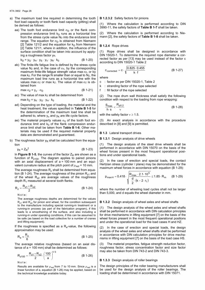
KTA 3902 Page 28
a) The maximum load line required in determining the tooth foot load capacity or tooth flank load capacity (pitting) shall be derived as follows:
aa) The tooth foot endurance limit σD or the flank com-pression endurance limit kD runs as a horizontal line from the stress cycle value ND into the endurance limit range. The equation for σD is obtained from Niemann [2] Table 121/2 and the equation for kD from Niemann [2] Table 121/1, where in addition, the influence of the surface condition shall be taken into account by apply-ing a roughness factor yR.
kD = yG ⋅ yH ⋅ yS ⋅ yV ⋅ yR ⋅ k0 (B 1-20)
ab) The finite-life fatigue line is defined by the stress cycle value NZ and, in the case of σX, by the corresponding maximum finite-life fatigue strength value max σZ, or by max kZ. For the range N smaller than or equal to NZ, the maximum load line runs as a horizontal line with the values max σZ or max kZ. The value of max σZ is ob-tained from
max σZ = yσ ⋅ σD (B 1-21)
ac) The value of max kZ shall be determined from
max kZ = yK ⋅ yG ⋅ yH ⋅ k0 (B 1-22)
ad) Depending on the type of loading, the material and the heat treatment, the values specified in Table B 1-5 for the determination of the maximum load line shall be adhered to, where yσ and yK are life cycle factors.
ae) The material property values σ0 of the tooth foot en-durance limit and k0 of the flank compression endur-ance limit shall be taken from Table B 1-6. Other ma-terials may be used if the required material property data are demonstrated and guaranteed.
b) The roughness factor yR shall be calculated from the equa-
tion
yR = ZR2 (B 1-23)
In Figure B 1-5, the curves of the factor ZR are shown as a function of Rz100. The diagram applies to paired pinions with an axial displacement of a = 100 mm and an equi-valent curvature radius at the pitch point of ρred = 10 mm.
The average roughness Rz shall be determined from equa-tion (B 1-24). The average roughness of the pinion Rz1 and of the wheel Rz2 are average values of the roughness depth R1 measured at several tooth flanks.
2
RRR 2z1z
z+
= (B 1-24)
N o t e :
The average roughness depths are determined for the values Rz1 and Rz2 for pinion and wheel, for the condition subsequent to the manufacture including special running-in treatment or a running-in process (as part of the fabrication program), if this leads to a smoothening of the surface, and also including a running-in under operating conditions, if this can be assumed to be safe (as based on the load collective for a number of cranes and lifting equipment).
If the roughness is specified as a Ra-value, the following approximation may be used:
6
RR z
a ≈ (B 1-25)
The average relative roughness (based on an axial dis-tance of a = 100 mm) shall be determined as follows:
3/1
2z1z100z a
100
2
RRR
⋅
+= (B 1-26)
N o t e :
Results are available for ρred from 7 to 10 mm. Since ρred is a linear function of a, equation (B 1-26) may be applied, based on the technical knowledge available today.
B 1.2.3.2 Safety factors for pinions
(1) Where the calculation is performed according to DIN 3990-11, the safety factors of Table B 1-7 shall be taken.
(2) Where the calculation is performed according to Nie-mann [2], the safety factors of Table B 1-8 shall be taken.
B 1.2.4 Rope drives
(1) Rope drives shall be designed in accordance with DIN 15020-1. To determine the required rope diameter a cor-rected factor as per [13] may be used instead of the factor c according to DIN 15020-1 Table 2
fk
455.0825.0cccorrected ⋅
⋅⋅= (B 1-27)
where
c : factor as per DIN 15020-1, Table 2
k : stranding factor of the rope selected
f : fill factor of the rope selected
(2) The rope drum wall thickness shall satisfy the following condition with respect to the loading from rope wrapping:
ν
<⋅
2.0pmax R
sh
S (B 1-28)
with the safety factor ν ≥ 1.5.
(3) An exact analysis in accordance with the procedure described in [8] and [9] is permitted.
B 1.3 Lateral transport drives
B 1.3.1 Design analysis of drive wheels
(1) The design analysis of the steel drive wheels shall be performed in accordance with DIN 15070 on the basis of the wheel forces present in the most frequent operational posi-tions and under operational loads.
(2) In the case of erection and special loads, the contact Hertzian stress (cylinder / plane) may be demonstrated for the maximum wheel forces in accordance with equation (B 1-29):
( )m
1
5max
Hmax R85.1
r2k2
d
101.2R418.0p ⋅≤
⋅−⋅
⋅⋅⋅= (B 1-29)
where the number of wheeling load cycles shall not be larger than 5,000, and d equals the wheel diameter in mm.
B 1.3.2 Design analysis of wheel axles and wheel shafts
(1) The design analysis of the wheel axles and wheel shafts shall be performed in accordance with DIN calculation principles for drive mechanisms in lifting equipment [7] on the basis of the wheel forces present in the most frequent operational positions and under the operational load for the load cases H and HZ.
(2) In the case of erection and special loads, the design analysis of the wheel axles and wheel shafts shall be performed in accordance with DIN calculation principles for drive mecha-nisms in lifting equipment [7] on the basis of the load case HS.
(3) The material properties, fatigue strength reduction factor, roughness factor, stress concentration factor and size factor may also be taken from DIN 743-2 and DIN 743-3.
B 1.3.3 Design analysis of roller bearings
The design principles of the roller bearing manufacturers shall be used for the design analysis of the roller bearings. The loading shall be determined in accordance with DIN 15071.
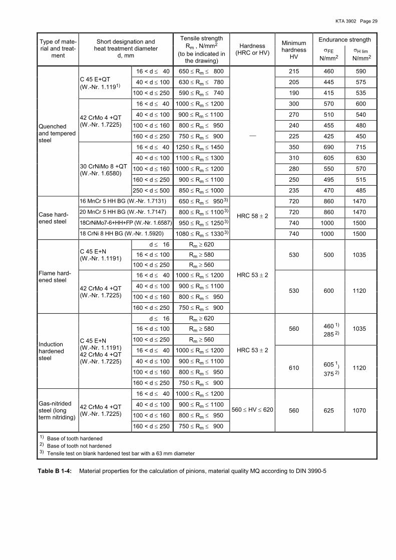
KTA 3902 Page 29
Type of mate-rial and treat-
ment
Short designation and heat treatment diameter
d, mm
Tensile strength Rm , N/mm2
(to be indicated in the drawing)
Hardness
(HRC or HV)
Minimum hardness
HV
Endurance strength
σFE
N/mm2
σH lim
N/mm2
Quenched and tempered steel
C 45 E+QT (W.-Nr. 1.1191)
16 < d ≤ 40 650 ≤ Rm ≤ 800 215 460 590
40 < d ≤ 100 630 ≤ Rm ≤ 780 205 445 575
100 < d ≤ 250 590 ≤ Rm ≤ 740 190 415 535
42 CrMo 4 +QT (W.-Nr. 1.7225)
16 < d ≤ 40 1000 ≤ Rm ≤ 1200 300 570 600
40 < d ≤ 100 900 ≤ Rm ≤ 1100 270 510 540
100 < d ≤ 160 800 ≤ Rm ≤ 950 240 455 480
160 < d ≤ 250 750 ≤ Rm ≤ 900 225 425 450
30 CrNiMo 8 +QT (W.-Nr. 1.6580)
16 < d ≤ 40 1250 ≤ Rm ≤ 1450 350 690 715
40 < d ≤ 100 1100 ≤ Rm ≤ 1300 310 605 630
100 < d ≤ 160 1000 ≤ Rm ≤ 1200 280 550 570
160 < d ≤ 250 900 ≤ Rm ≤ 1100 250 495 515
250 < d ≤ 500 850 ≤ Rm ≤ 1000 235 470 485
Case hard-ened steel
16 MnCr 5 HH BG (W.-Nr. 1.7131) 650 ≤ Rm ≤ 950 3) 720 860 1470
20 MnCr 5 HH BG (W.-Nr. 1.7147) 800 ≤ Rm ≤ 1100 3) HRC 58 ± 2
720 860 1470
18CrNiMo7-6+HH+FP (W.-Nr. 1.6587) 950 ≤ Rm ≤ 1250 3) 740 1000 1500
18 CrNi 8 HH BG (W.-Nr. 1.5920) 1080 ≤ Rm ≤ 1330 3) 740 1000 1500
Flame hard-ened steel
C 45 E+N (W.-Nr. 1.1191)
d ≤ 16 Rm ≥ 620
16 < d ≤ 100 Rm ≥ 580 530 500 1035
100 < d ≤ 250 Rm ≥ 560
42 CrMo 4 +QT (W.-Nr. 1.7225)
16 < d ≤ 40 1000 ≤ Rm ≤ 1200 HRC 53 ± 2
40 < d ≤ 100 900 ≤ Rm ≤ 1100 530 600 1120
100 < d ≤ 160 800 ≤ Rm ≤ 950
160 < d ≤ 250 750 ≤ Rm ≤ 900
Induction hardened steel
C 45 E+N (W.-Nr. 1.1191) 42 CrMo 4 +QT (W.-Nr. 1.7225)
d ≤ 16 Rm ≥ 620 460 1)
285 2)
16 < d ≤ 100 Rm ≥ 580 560 1035
100 < d ≤ 250 Rm ≥ 560
16 < d ≤ 40 1000 ≤ Rm ≤ 1200 HRC 53 ± 2
40 < d ≤ 100 900 ≤ Rm ≤ 1100 610
605 1)
375 2) 1120
100 < d ≤ 160 800 ≤ Rm ≤ 950
160 < d ≤ 250 750 ≤ Rm ≤ 900
Gas-nitrided steel (long term nitriding)
42 CrMo 4 +QT (W.-Nr. 1.7225)
16 < d ≤ 40 1000 ≤ Rm ≤ 1200
40 < d ≤ 100 900 ≤ Rm ≤ 1100 560 ≤ HV ≤ 620 560 625 1070
100 < d ≤ 160 800 ≤ Rm ≤ 950
160 < d ≤ 250 750 ≤ Rm ≤ 900
1) Base of tooth hardened 2) Base of tooth not hardened 3) Tensile test on blank hardened test bar with a 63 mm diameter
Table B 1-4: Material properties for the calculation of pinions, material quality MQ according to DIN 3990-5

KTA 3902 Page 30
Type of material and treatment
Load capacity of the tooth foot
Load capacity of the tooth flank
ND NZ yσ ND NZ yK
Tempered steel 3⋅106 104 2.5 5⋅107 105 2.56
Case hardened, induction hardened or recirculation hardened steel
3⋅106 103 2.5 5⋅107 105 2.56
Gas-nitrided steel 3⋅106 103 1.6 2⋅106 105 1.69
Table B 1-5: Parameters for the determination of the maxi-mum load line
=
=
= 2
0
2
2
2
0
0
02
0
N/mm19.0
N/mm
k
k
N/mm
k
k
14.0
15.5
23.0
N/mm
76 8 1095
0.8
1 2 43
1.1
1.0k N/mm27.5
131211
0.9
14
R
R
Z
z100
≤
≤
Figure B 1-5: Dependence of the factor ZR on the average relative roughness Rz100
Type of mate-rial and
treatment
Short designation and heat treatment diameter
d, mm
Tensile strength Rm , N/mm
2
(to be indicated in the drawing)
Hardness
(HRC or HV)
Minimum hardness
HV
Endurance strength
σFE
N/mm2
σH lim
N/mm2
C 45 E+QT (W.-Nr. 1.1191)
16 < d ≤ 40 650 ≤ Rm ≤ 800 215 4.2 235
40 < d ≤ 100 630 ≤ Rm ≤ 780 205 4.0 230
100 < d ≤ 250 590 ≤ Rm ≤ 740 190 3.5 220
42 CrMo 4+QT (W.-Nr. 1.7225)
16 < d ≤ 40 1000 ≤ Rm ≤ 1200 300 9.0 320
Quenched and tempered steel
40 < d ≤ 100 900 ≤ Rm ≤ 1100 270 8.5 310
100 < d ≤ 160 800 ≤ Rm ≤ 950
240 7.8 300
160 < d ≤ 250 750 ≤ Rm ≤ 900 225 7.3 290
30 CrNiMo 8+QT (W.-Nr. 1.6580)
16 < d ≤ 40 1250 ≤ Rm ≤ 1450 350 13.0 390
40 < d ≤ 100 1100 ≤ Rm ≤ 1300 310 12.0 370
100 < d ≤ 160 1000 ≤ Rm ≤ 1200 280 11.1 350
160 < d ≤ 250 900 ≤ Rm ≤ 1100 250 10.0 340
250 < d ≤ 500 850 ≤ Rm ≤ 1000 235 9.5 320
Case hard-ened steel
16 MnCr 5 HH BG (W.-Nr. 1.7131) 650 ≤ Rm ≤ 950 3)
HRC 58 ± 2
720 50 420
20 MnCr 5 HH BG (W.-Nr. 1.7147) 800 ≤ Rm ≤ 1100 3) 720 50 420
18CrNiMo7-6+HH+FP (W.-Nr. 1.6587) 950 ≤ Rm ≤ 1250 3) 740 50 470
18 CrNi 8 HH BG (W.-Nr. 1.5920) 1080 ≤ Rm ≤ 1330 3) 740 50 470
Flame hard-ened steel
C 45 E+N (W.-Nr. 1.1191)
d ≤ 16 Rm ≥ 620
16 < d ≤ 100 Rm ≥ 580 530 23 284
100 < d ≤ 250 Rm ≥ 560
42 CrMo 4 +QT (W.-Nr. 1.7225)
16 < d ≤ 40 1000 ≤ Rm ≤ 1200 HRC 53 ± 2
40 < d ≤ 100 900 ≤ Rm ≤ 1100 560 27 340
100 < d ≤ 160 800 ≤ Rm ≤ 950
160 < d ≤ 250 750 ≤ Rm ≤ 900
Induction hardened steel
C 45 E+N (W.-Nr. 1.1191)
d ≤ 16 Rm ≥ 620 260 1)
160 2) 16 < d ≤ 100 Rm ≥ 580 560 23
100 < d ≤ 250 Rm ≥ 560
42 CrMo 4 +QT (W.-Nr. 1.7225)
16 < d ≤ 40 1000 ≤ Rm ≤ 1200 HRC 53 ± 2
40 < d ≤ 100 900 ≤ Rm ≤ 1100 610 27
340 1)
210 2) 100 < d ≤ 160 800 ≤ Rm ≤ 950
160 < d ≤ 250 750 ≤ Rm ≤ 900
Gas-nitrided steel (long term nitriding)
42 CrMo 4 +QT (W.-Nr. 1.7225)
16 < d ≤ 40 1000 ≤ Rm ≤ 1200
40 < d ≤ 100 900 ≤ Rm ≤ 1100 560 ≤ HV ≤ 620 560 27 350 100 < d ≤ 160 800 ≤ Rm ≤ 950
160 < d ≤ 250 750 ≤ Rm ≤ 900
1) Base of tooth hardened 2) Base of tooth not hardened 3) Tensile test on blank hardened test bar with a 63 mm diameter
Table B 1-6: Material properties for the calculation of pinions according to Niemann [2]

KTA 3902 Page 31
Analytical proof Loading type Equation for proof of safety Required safety factor for additional re-quirements according to section 6
Static strength
First step of collective
1min
F
FGF max
σ
σ=σ ≥ 1.40
11min
H
HGH maxS
σ
σ= ≥ 1.12
Proof only required if Nges < NZ
Cyclic strength
Load collective Case A or B
F
FGFmin
Sσ
σ= ≥ 1.57
H
HGHmin
Sσ
σ= ≥ 1.12
Endurance strength
First step of collective Case C
1
minF
FGFS
σ
σ= ≥ 1.57
1
minH
HGHS
σ
σ= ≥ 1.12
Table B 1-7: Safety factors for pinions according to DIN 3990-11
Proof of Loading type Equation for proof of safety Required safety factor for additional re-
quirements according to section 6
Static strength
First step of collective
1
zmax1 σ
σ=νσ ≥ 1.35
1
zk k
kmax
1=ν
≥ 1.25
Proof only required if Nges < NZ
Cyclic strength
Load collective Case A or B
σσ
=νσD ≥ 2.0
k
kDk =ν ≥ 1.3
Endurance strength
First step of collective Case C
1
D
σσ
=νσ ≥ 2.0
1
Dk k
k=ν ≥ 1.3
Table B 1-8: Safety factors for pinions according to Niemann [2]
B 1.4 Load carrying devices
B 1.4.1 Supporting means
B 1.4.1.1 Load hooks
Unless load hooks according to DIN 15401-1 and DIN 15401-2 or DIN 15402-1 and DIN 15402-2 are used, a design analysis following DIN 15400 is required.
B 1.4.1.2 Load hook mountings
(1) The design analysis of the load hook cross-bar shall be performed in accordance with section B 1.2.
(2) Unless a load hook nut according to DIN 15413 is used, a design analysis following DIN 15400 is required.
(3) In the case of statically loaded roller bearings (only slight rotary motion), the design principles of the roller bearing man-ufacturers shall be used with static loads for the design analy-sis of the roller bearings.
B 1.4.1.3 Grabs, lifting beams and hangers
The design analysis for supporting structures shall be per-formed in accordance with section B 1.1 and for machine elements in accordance with section B 1.2.
B 1.4.1.4 Top and bottom blocks
(1) The design forces for the rope sheaves required for the demonstration of suitability under KTA 3903 shall be deter-mined in accordance with section B 1.2.
(2) In the case of statically loaded roller bearings with only slight rotary motion, the design principles of the roller bearing manufacturers shall be applied with static loads for the design analysis of the roller bearings.
(3) The design analysis for supporting structures shall be performed in accordance with section B 1.1 and for machine elements in accordance with section B 1.2.

KTA 3902 Page 32
B 1.4.1.5 Bolted connections
(1) The stress analysis shall be performed according to VDI 2230 Sheet 1 for bolted connections with additional tensile loading, in which case the following requirements shall be met:
a) the usage factor of the yield stress during tightening shall be limited to 0.7,
b) the usage factor of the yield stress due to additional forces from operating conditions shall be limited to 0.1.
(2) The fatigue analysis shall be performed according to VDI 2230 Sheet 1, in which case a safety factor of 2.0 against the stress amplitude of the endurance or of the finite-life fa-tigue strength shall be satisfied.
(3) In case of a multi-step load collective (e.g. due to as-sembly and disassembly activities), the loading history cov-ered by the stress analysis as per (1) shall be modelled as damage-equivalent single-step stress collective. The damage-equivalent stress pertinent to the number of stress cycles ND shall be determined as follows in the analysis of finally quenched and tempered bolts:
c
1
D
c
1
i
ii
1 N
N
σ
σ⋅
⋅σ=σ∑
(B 1-30)
where the following is to be used:
ND = 2 ⋅ 106
c = 3
with:
σ1 actual stress amplitude of 1st step of load collective step (maximum stress)
σi actual stress amplitude of the respective step of load collective
Ni actual number of stress cycles of the respective step of load collective
The following shall be verified:
ν = σ
σ ASV ≥ 2.0 (B 1-31)
with:
σASV stress amplitude of endurance limit of finally quenched and tempered bolts according to VDI 2230 Sheet 1
N o t e :
Where in the analysis of final-rolled bolts, the stress amplitude of the endurance limit is determined in a suitable manner in due con-sideration of its dependence on the mean stress, the damaging-equivalent stress may be determined analogously by using σASG (stress amplitude of endurance limit of final-rolled bolts in accord-ance with VDI 2230 Sheet 1) in lieu of σASV and c=6.
B 1.4.2 Load suspension devices
The requirements of section B 1.4.1 apply to load suspension devices.
B 2 Load cases and analytical proofs for cranes, winch-es, trolleys as well as load carrying devices under section 7 and for refueling machines under section 8
B 2.1 Structures
B 2.1.1 Performance of proof using the global safety factor concept
B 2.1.1.1 Erection and operational loads
(1) The calculation shall be performed in accordance with DIN 15018-1. For structural members made of the austenitic steels 1.4541, 1.4306 and 1.4571 according to DIN EN 10088-2 or DIN EN 10088-3 the allowable stresses shall be taken from section D 1.
(2) The verification procedure according to section 4.3 of KTA 3205.1 shall be used for all external events.
(3) Where the operating conditions are exactly known, e.g. the actually occurring loadings and stress cycles, the verifica-tion of service strength may be performed for a single-step or multi-step load collective on the basis of a stress-number diagram according to Annex C for the steels S235 and S355, or on the basis of a stress-number diagram according to sec-tion D 2 for the austenitic steels 1.4541, 1.4306 and 1.4571.
In this respect, the requirements of clause B 1.1.1 (3) apply, in which case the following safety factor as regards the allowa-ble maximum stress shall be observed:
σσ=ν /D ≥ 1.25. (B 2-1)
B 2.1.1.2 Special load case - load shifting
The effects of stresses resulting from load shifting shall be analysed as special load case (special load case HS) in ac-cordance with DIN 15018-1. The stresses required as input to this calculation shall be taken from the analytical proof in ac-cordance with section B 2.2.
B 2.1.2 Performance of proof using the partial safety factors concept
B 2.1.2.1 Erection and operational loads
(1) The calculation shall be performed in accordance with DIN EN 13001-3-1 in conjunction with DIN EN 13001-1 and DIN EN 13001-2 using the specifications given in (2).
A design of structural members using austenitic steels within the partial safety factors concept is permitted only in those cases where the fatigue analysis may be waived according to section 6.3.3 of DIN EN 13001-3-1, in which case the number of stress cycles shall be determined according to section B 1.2.1.2.
(2) The procedure of proof according to DIN EN 13001-3-1 in conjunction with DIN EN 13001-1 and DIN EN 13001-2 shall be conducted in compliance with the following requirements:
a) Regardless of the specific conditions of crane design and operation, the dynamic factor Φ2 used in the proof accord-ing to DIN 13001-2 shall be calculated by applying the fol-lowing formulae:
aa) for operational loads: Φ2 = 1.4 + 0.528 ⋅ vh,max
ab) for erection loads: Φ2 = 1.1 + 0.132 ⋅ vh,max
For vh,max the maximum hoisting speed relevant for the load case in question shall be inserted.

KTA 3902 Page 33
b) Where a dynamic factor less than that resulting from a) is to be used, the maximum dynamic load factor occurring during one working cycle shall be determined by means of calculation or experimentally in each individual case. As re-gards the determination of the dynamic factor this dynamic load factor shall be multiplied by a safety factor of 1.25.
c) The requirements of clauses B 1.1.2 (2) c) to g) apply.
d) The test loads shall be as follows:
da) for cranes, winches, trolleys, load suspending devices and refueling machines as specified in KTA 3903 Ta-ble 8-1 ser. no. 1.4,
db) for load suspension devices and lifting accessories as specified in KTA 3903 Table 8-1 ser. no. 2.4.
The proof shall be performed in accordance with the re-quirements in section 4.2.4.3 of DIN EN 13001-2 using the test loads as specified under da) and db) and the dynamic factor as specified under a).
e) The fatigue strength specific resistance factor γmf in the fatigue analysis according to DIN EN 13001-3-1 shall be taken as γmf = 1.5 for parts and welded connections as well as for bolted connections which are not hot dip galvanised, and as γmf = 1.8 for hot dip galvanised bolted connections.
f) Based on the specifications as per a) through e), the risk coefficient γn according to DIN EN 13001-2 may be taken as 1.0.
(3) The following procedures shall be used to demonstrate the safety against all external events:
a) either the procedure according to DIN EN 13001-3-1 using the following resistance and partial safety factors
γm = 1.0
γP = 1.0
where in the case of parts and welded connections made of austenitic steels the Rp1.0 proof stress may be used as fy instead of the Rp0.2 proof stress,
or
b) the procedure according to section 4.2 of KTA 3205.1.
(4) Where the operating conditions are exactly known, e.g. the actually occurring loadings and stress cycles, the fatigue analysis may be performed for a single-step or multi-step load collective in accordance with the requirements of DIN EN 13001-3-1 and the specifications in (2).
N o t e :
The relationship between number of stress cycles and number of working cycles can be derived from section B 1.2.1.2.
The analytical proof based on a multi-step stress-number diagram shall be performed in due consideration of a damage-equivalent stress to the linear damage rule (Miner rule) ac-cording to formula (B 1-14).
The following safety factor as regards the allowable stress range shall be observed:
25.1Sd
Rd ≥σ∆
σ∆=ν . (B 2-2)
B 2.1.2.2 Special load case - load shifting
The effects of stresses resulting from load shifting shall be analysed as load combination C in accordance with DIN EN 13001-2. The stresses required as input to this calculation shall be taken from the analytical proof in accordance with section B 2.2.
B 2.1.3 Alternative ways of analytical proof
The stipulations of section B 1.1.3 apply.
B 2.2 Hoists
B 2.2.1 Design data
B 2.2.1.1 Determination of moments and forces
(1) The moments specified in Tables B 2-1 and B 2-2 shall be determined for the design of parts of the drive mechanism chain, starting with the service brake and ending with the rope drum.
N o t e : When using systems to ascertain the braking effect without test load for in-service inspection, see also KTA 3903, Annex D, sec-tion D 3.1.
Load case no.
Mo-ments
Nomenclature Type of proof
1
TM
$TM
Static moment for the maxi-mum erection load
Dynamic moment for the maximum erection load TM (largest value of $TBS , $TBR , $TAN )
Fatigue analysis and static stress ana-lysis for the first step of the load collective
2
TB $TB
Static moment for the maxi-mum operational load
Dynamic moment for the maximum operational load TB (largest value of $TBS , $TBR , $TAN )
3
T0
0T̂
Static moment for idling runs if the dead weight of half the supporting means plus load suspension devices plus lifting accessory is larger than 30 % of the maximum load
Dynamic moment for the dead weight T0 (largest value
of $TBS , $TBR , $TAN )
4
TSO
$TSO
Maximum moment for the special load case, e.g. accep-tance test, in-service inspec-tion, gear box test run, simul-taneous engagement of the service and auxiliary brake
Dynamic moment for the special load TSO
5
TBS1
$TBS1
Static moment for the entire operational load carried by one drive mechanism chain (second drive mechanism chain does not carry)
Dynamic moment for the entire operational load car-ried by one drive mechanism chain (second drive mecha-nism chain does not carry) (largest value of $TBS , $TBR , $TAN )
6 $TBAS1
Dynamic moment for load shifting under operational load in one drive mechanism chain
Static stress analysis
Table B 2-1: Moments for a double drive mechanism chain

KTA 3902 Page 34
Load case no.
Mo-ments
Nomenclature Type of proof
1
TM
$TM
Static moment for the maxi-mum erection load
Dynamic moment for the maximum erection load TM (largest value of $TBS , $TBR , $TAN )
Fatigue analysis and static tress analy-sis for the first step of the load collective
2
TB
$TB
Static moment for the maxi-mum operational load
Dynamic moment for the maximum operational load TB (largest value of $TBS , $TBR , $TAN )
3
T0
0T̂
Static moment for idling runs if the dead weight of half the supporting means plus load suspension devices plus lifting accessory is larger than 30 % of the maximum load
Dynamic moment for the dead weight T0 (largest value
of $TBS , $TBR , $TAN )
4
TSO
$TSO
Maximum moment for the special load case, e.g. accep-tance test, in-service inspec-tion, gear box test run, simul-taneous engagement of the service and auxiliary brake
Dynamic moment for the special load TSO
5 $TBAS2
Dynamic moment for the vibration effect of the safety brake under the governing operational load case
6 $TBAS1
Dynamic moment for load shifting under operational load in one drive mechanism chain
Static stress analysis
Table B 2-2: Moments for drive mechanism chain with safety brake
(2) The calculation of the moments $TM , $TB , $TO , $TSO and
1BST̂ shall be based on the operating conditions in accordance
with clause B 1.2.1.1 (2). The moments shall be calculated for
those intersections that are to be analysed individually. The
moment 1BAST̂ shall be determined from the load shifting
analysis under maximum operational load.
For the determination of 2BAST̂ the drive mechanism shall be
modelled by a suitable model, and its dynamic behaviour shall
be proved to be verifiable by the method of Stenkamp [12] or
by using a numerical simulation procedure. A damping factor
D = 0.05 may be used if no analytical proof is performed for
the individual case.
The flexibility Ci of a spring is given by Ci = NG
1, with Ci in
Nm/rad and the torsional pliability NG in rad/Nm. The equa-tions for determining the torsional pliability are specified in Table B 2-3 for typical gear box parts.
(3) The design forces of non-rotating machine elements between rope drum and load shall be determined from the moments specified above.
(4) In the case of a non-redundancy of parts between rope drum and load, 1.25 times the dynamic factor shall be used in the calculation of these parts.
B 2.2.1.2 Determination of the number of stress cycles
The number of stress cycles required for the fatigue analysis shall be determined in accordance with section B 1.2.1.2.
B 2.2.1.3 Determination of the (general) load collective
From the determined moments in accordance with Table B 2-1 or B 2-2 and the resulting forces, the stresses in the part shall be calculated and sorted according to size. With the correspond-ing stress cycles, the load collective shall be established. This load collective shall be compared to the part's stress-number diagram in accordance with section B 1.2.1.3.
B 2.2.2 Shafts, axles and similar parts
B 2.2.2.1 Determination of the stress-number diagram
The requirements under section B 1.2.2.1 shall apply.
B 2.2.2.2 Safety factors for shafts, axles and similar parts
(1) The safety factors specified in Table B 2-4 shall apply.
(2) When using the finite element method, the requirements of section B3 shall be met.
B 2.2.2.3 Analytical proofs for parallel keys
(1) The requirements under section B 1.2.2.3 shall apply.
(2) For stresses resulting from the load cases “Load shifting“ and “Engagement of safety brake“ the allowable contact stresses can be taken as
pzul = 0.9 ⋅ Rp0.2 (ReH) (B 2-3)
B 2.2.3 Pinions
B 2.2.3.1 Determination of the effective stresses and of the load capacity
The requirements under section B 1.2.3.1 shall apply.
B 2.2.3.2 Safety factors for pinions
(1) If the calculation procedure according to DIN 3990-11 is used the safety factors specified in Table B 2-5 shall apply.
(2) If the analysis procedure of Niemann [2] is used for de-termining the strength of pinions, the safety factors specified in Table B 2-6 shall apply.
B 2.2.4 Rope drives
(1) The rope drive shall be calculated in accordance with section B 1.2.4.
(2) With regard to the analytical proof of the rope drum wall
thickness and the rope fasteners on the drum, it is allowed to
neglect those stress peaks from 1BAST̂ and 2BAST̂ that very
rarely occur and then for only very short time periods, since
they affect only a fraction of a rope wrap.

KTA 3902 Page 35
Sketch Equation
1. Shaft
d
NGl
G d=
⋅
⋅ ⋅
324π
G : Modulus of rigidity
l : Shaft length
2. Sleeve
id d
( )NG
l
G d d d=
⋅
⋅ ⋅ ⋅ −
32
141
4π /
3. Shaft with groove for parallel key
b
t
d
α⋅⋅π⋅
⋅=
4dG
l32NG
_____________
( )( ) ( )
( )α
π
π σ ψ
π σ ψ ψ π σ ψ ψ σ
π σ ψ=
⋅
− ⋅ ⋅−
⋅ ⋅ +−
⋅ ⋅ ⋅ − ⋅
⋅ − ⋅ ⋅
32
4 32
1
12
1
4 4
3
4
4 2 2 2
2
_____________
( )( ) ( )
απ
π σ ψ
π σ ψ ψ σ ψ ψ σ=
⋅
− ⋅ ⋅−
⋅ ⋅ +−
⋅ ⋅ − ⋅
32
832
1
6
1
2
3
2 4
4 2 2 2
σ = t/b ψ = b/d
4. Splinted shaft
d
b
D
α⋅⋅π⋅
⋅=
4dG
l32NG
( ) ( )[ ]α π β δ= − ⋅ ⋅ −1 1 1 42
/ /z
β = b/d
δ = D/d
l : Shaft length
z : Number of splines
5. Parallel key connection
t
b
d
tbd
4.6NG
2 ⋅⋅=
d, b, t in mm
6. Splined-shaft connection
t
d
b
ztbd
4NG
2 ⋅⋅⋅=
d, b, t in mm
7. Gear coupling
t
D
b
α⋅β⋅⋅⋅
=tbD
4NG
2
α = (3 to 4) β = (4 to 5) for z = (6 to 8)
d, b, t in mm
z : Number of teeth
8. Cluster gear (steel)
rb
Kcosrb
1NG
22⋅
α⋅⋅⋅=
K = 6 ⋅ 10-2 Straight tooth gearing K = 3.6 ⋅ 10-2 Spiral tooth gearing K = 4.4 ⋅ 10-2 Internal tooth gearing
α : Pressure angle
b, r in mm
Table B 2-3: Equations for the determination of the torsional pliability NG [rad/Nm] of typical gear box parts

KTA 3902 Page 36
Analytical proof
Loading type
Equation for proof of safety
Required safety factor for increased requirements according to
section 7 and for refueling machines
Static strength
First step of the collective
1)
( )ν σ σ ασ1 1= ⋅x kn/
≥ 1.35
( )ν τ τ ατ1 1= ⋅St k t/
Failure of a part for a double drive mechanism chain 2)
( )ν σ σ ασBAS x BAS kn1 1
= ⋅/ $
( )ν τ τ ατBAS St BAS kt1 1
= ⋅/ $
ν σ σσBAS
Vx VBAS1 1
= / $
Failure of a part for a single drive mechanism chain with safety brake 2)
( )ν σ σ ασBAS x BAS kn1 1
= ⋅/ $
( )ν τ τ ατBAS St BAS kt1 1
= ⋅/ $
ν σ σσBAS
Vx VBAS1 1
= / $
( )ν σ σ ασBAS x BAS kn2 2
= ⋅/ $
( )ν τ τ ατBAS St BAS kt2 2
= ⋅/ $
ν σ σσBAS
Vx VBAS1 1
= / $
Cyclic strength Load collective Case A or B
ν σ σσ = D /
≥ 2.5
ν τ ττ = D /
σσ
ττ ν
n
D
t
D
+
≤
2 2 210,
Endurance strength
First step of collective Case C
ν σ σσ = D / 1
ν τ ττ = D / 1
σ
σ
τ
τ ν1
21
2 210
D D
+
≤
,
1) Applies only to hoists; in the case of non-rotating parts no stress concentration factors are needed and the required safety factor shall be ≥ 1.5 with σx being replaced by ReH or Rp0.2.
2) Same as footnote 1), however, the required safety factor shall be ≥ 1.25.
Table B 2-4: Safety factors for shafts, axles and similar parts

KTA 3902 Page 37
Analytical proof
Loading type
Equation for proof of safety
Required safety factor for increased requirements according
to section 7 and for refueling machines
Static strength
First step of collective
1
minF
FGF max
σ
σ=σ ≥ 1.57
11min
H
HGH maxS
σ
σ= ≥ 1.25
Proof only required if Nges < NZ
Failure of a part for a double drive mechanism chain
1BASmin1BAS
F
FGF maxS
σ
σ=
Failure of a part for a single drive mechanism chain with safety brake 2)
1BASmin1BAS
F
FGF maxS
σ
σ= ≥ 1.57
2BASmin2BAS
F
FGF maxS
σ
σ=
Cyclic strength
Load collective Case A or B
F
FGFmin
Sσ
σ= ≥ 1.76
H
HGHmin
Sσ
σ= ≥ 1.25
Endurance strength
First step of collective Case C
1
minF
FGFS
σ
σ= ≥ 1.76
1
minH
HGHS
σ
σ= ≥ 1.25
Table B 2-5: Safety factors for pinions according to DIN 3990-11
Analytical proof
Loading type
Equation for proof of safety
Required safety factor for increased requirements according
to section 7 and for refueling machines
Static strength
First step of collective
1
zmax1 σ
σ=νσ ≥ 1.50
1
zk k
kmax
1=ν
≥ 1.25
Proof only required if Nges < NZ
Failure of a part for a double drive mechanism chain
1
1BAS
zBAS ˆ
maxσ
σ=ν
Failure of a part for a single drive mechanism chain with safety brake
1
1BAS
zBAS ˆ
maxσ
σ=ν
≥ 1.35
2
2BAS
zBAS ˆ
maxσ
σ=ν
Cyclic strength Load collective Case A or B
σσ
=νσD ≥ 2.5
k
kDk =ν ≥ 1.6
Endurance strength
First step of collective Case C
1
D
σσ
=νσ ≥ 2.5
1
Dk
k
k=ν ≥ 1.6
Table B 2-6: Safety factors for pinions according to Niemann [2]
KTA 3902 Page 38
B 2.3 Lateral transport drives
The requirements in accordance with section B 1.3 shall apply.
B 2.4 Load carrying devices
(1) The requirements under section B 1.4 shall apply.
(2) Section B 2.1 applies to the analytical proofs of support-ing structures.
(3) Section B 2.2 applies to the analytical proofs of the ma-chine parts of load hook mounting, grabber, lifting beam and sling, and to the top and bottom blocks.
(4) Section B 1.4.1.5 applies to bolted connections, for the fatigue analysis, however, a safety factor of at least 2.5 shall be verified.
B 3 Analytical proof using the finite element method
B 3.1 General
(1) Besides the analytical proofs described in sections B1 and B2 it is also permitted to perform strength analyses on the basis of the finite element method (FEM) for supporting struc-tures as well as non-rotating machine parts.
(2) When using the finite element method, the requirements of KTA 3201.2, Annex C3 shall be met.
(3) Analytical proofs using finite element calculations are permitted both for proofs based on DIN 15018-1 and for proofs based on DIN EN 13001-3-1.
(4) In the case of proofs based on DIN 15018-1, deviating from the requirements in sections 6, 7 and 8 as well as sec-tions B 1 and B 2 the requirements of section B 3.2 apply to the stress analysis using the finite element method.
(5) In the case of proofs using the partial safety factors concept according to DIN EN 13001-3-1, deviating from the requirements in sections 6, 7 and 8 as well as sections B 1 and B 2 the requirements of section B 3.3 apply to the stress anal-ysis using the finite element method.
B 3.2 Stress analysis for supporting structures using the global safety factor concept in proofs according to DIN 15018-1 and for non-rotating machine parts
B 3.2.1 Stress analysis
(1) Stresses shall be classified in dependence of the cause of stress and its effect on the mechanical behaviour of the part as per section 7.7.2 of KTA 3201.2 into stress categories, i.e. primary stresses, secondary stresses and peak stresses.
(2) For supporting structures and non-rotating machine parts only primary stresses remote from discontinuities shall be considered.
(3) Primary stresses (P) are stresses which satisfy the laws of equilibrium of external forces and moments (loads). Here, membrane stresses (Pm) are defined as the average value of the respective stress component over the section governing the load-bearing behaviour, in the case of plate or shell type structures the average value of the respective stress compo-nent distributed across the thickness. Primary bending stress-es (Pb) are defined as stresses that can be altered linearly across the considered section and proportionally to the dis-tance from the neutral axis, in the case of plate or shell type structures as the portion of the stresses distributed across the thickness that can be altered linearly.
(4) The equivalent stress intensity shall be derived from the linearised individual stress components.
(5) The location of linearisation outside the area of influence of geometric discontinuities shall be selected such that
a) only primary stress components are covered,
b) the maximum sum of primary stress components is covered.
(6) The requirements of (5) a) und (5) b) are deemed to have generally been met if
a) linearisation is effected at a distance sR ⋅ to the geomet-ric discontinuity in the case of shell-like parts (e.g. skirts, pipes) where R and s are defined as follows:
R : mean smallest radius of shell
s : smallest wall thickness
b) linearisation is effected at a distance of half the section diameter in the case of round steel sections, at a distance of half the smallest dimension of cross-section in the case of rectangular steel sections, sheets and plates,
c) linearisation is effected at a distance sR ⋅ to the geomet-ric discontinuity in the case of other shapes where R and s are defined as follows:
R : half the smallest dimension of rolled section, half the smallest leg width of angle section, radius of bore.
s : smallest wall thickness
Linearisation may also be effected at other distances, but a suitable analytical proof as regards compliance with the re-quirements of (5) a) and (5) b) shall be performed.
(7) The following shall apply to the equivalent stress intensi-ty derived from the linearised stress components:
a) Remote from the discontinuity the equivalent stress inten-sity due to the load combinations to be proofed according to DIN 15018-1 shall not exceed the allowable stresses specified in DIN 15018-1.
b) At the discontinuity the equivalent stress intensity may exceed the allowable stresses specified in DIN 15018-1 provided, both the equilibrium of stresses due to local stress redistributions and the allowable stresses are com-plied with and the equivalent stress intensity does not ex-ceed the following value:
ba) for load case H σv ≤ 0.8 · Rp0.2
bb) for load case HZ σv ≤ 0.9 · Rp0.2
bc) for load case HS σv ≤ Rp0.2
with Rp0.2 : yield strength
Here, plausibility checks are allowed to demonstrate pos-sible stress redistributions.
c) The stress limitation for σv at the discontinuity need not be satisfied if it can be proved by means of a limit analysis that the allowable lower limit load as per section 7.7.4 of KTA 3201.2 are not exceeded in which case, for the pur-pose of calculating the lower bound collapse load, the fol-lowing yield stress values shall be taken
ca) in load case H: σF = 1.0 ⋅ Rp0.2
cb) in load case HZ: σF = 1.10 ⋅ Rp0.2
cc) in load case HS: σF = 1.20 ⋅ Rp0.2
and the specified load shall not exceed 67 % of the lower bound collapse load in accordance with section 7.7.4.1 of KTA 3201.2.
(8) For the evaluation as per (7) the equivalent stress inten-sity to be taken shall be the maximum of
a) the equivalent stress intensity according to the von Mises theory and
b) the largest principal stress.
(9) For the allowable stresses of weld seams DIN 15018-1 shall apply.
KTA 3902 Page 39
B 3.2.2 Fatigue analysis
(1) For supporting structures, the allowable stresses to be used in the fatigue analysis shall be determined to meet the requirements of DIN 15018-1.
(2) The fatigue analysis when using the finite element meth-od differs from the procedures under sections B 1 and B 2 only with respect to the determination of the nominal stress. Here, the stress intensity determined by means of the stress analysis shall be evaluated on the basis of the linearised indi-vidual stress components.
(3) For non-rotating machine parts, the fatigue analysis shall be performed in accordance with sections B 1.2.2 and B 2.2.2 and with the required safety factors shown in Table B 1-3 and Table B 2-4.
(4) The fatigue strength reduction factor may also be deter-mined on the basis of a FEM analysis alternatively to the re-quirements of B 1.2.2.1 (3). In this case, the fatigue strength reduction factor is the quotient of maximum equivalent stress intensity (non-linerarised) and the equivalent stress intensity derived from primary membrane and bending stresses as per subclause (1).
B 3.3 Stress analysis for supporting structures using the partial safety factors concept according to DIN EN 13001-3-1
B 3.3.1 Static stress analysis
(1) Stresses shall be determined using the loads, load com-binations and partial safety factors according to Table 12a of DIN EN 13001-2 and the requirements specified in sections B 1 and B 2.
(2) The stresses so determined shall be classified in de-pendence of the cause of stress and its effect on the mechan-ical behaviour of the part as per KTA 3201.2, section 7.7.2 into stress categories, i.e. primary stresses, secondary stresses and peak stresses.
(3) Remote from discontinuities only primary stresses shall be considered (cf. clause B 3.2.1 (3)).
(4) The equivalent stress intensity shall be derived from the linearised individual stress components.
(5) The location of linearisation outside the area of influence of geometric discontinuities shall be selected such that
a) only primary stress components are covered,
b) the maximum sum of primary stress components is cov-ered.
(6) The requirements of (5) a) und (5) b) are deemed to have generally been met if
a) linearisation is effected at a distance sR ⋅ to the geomet-
ric discontinuity in the case of shell-like parts (e.g. skirts, pipes) where R and s are defined as follows:
R : mean smallest radius of shell
s : smallest wall thickness
b) linearisation is effected at a distance of half the section diameter in the case of round steel sections, at a distance of half the smallest dimension of cross-section in the case of rectangular steel sections, sheets and plates,
c) linearisation is effected at a distance sR ⋅ to the geomet-ric discontinuity in the case of other shapes where R and s are defined as follows:
R : half the smallest dimension of rolled section, half the smallest leg width of angle section, radius of bore.
s : smallest wall thickness
Linearisation may also be effected at other distances, but a suitable analytical proof as regards compliance with the re-quirements of (5) a) and (5) b) shall be performed.
(7) The following shall apply to the equivalent stress intensi-ty derived from the linearised stress components:
a) Remote from the discontinuity the equivalent stress inten-sity due to the load combinations in consideration of partial safety factors shall not exceed the limit design stress fRd according to section 5.2 of DIN EN 13001-3-1.
b) At the discontinuity the equivalent stress intensity due to the load combinations in consideration of partial safety fac-tors may exceed the limit design stress fRd provided, both the equilibrium of stresses due to local stress redistribu-tions and the limit design stress are complied with and the equivalent stress intensity does not exceed the following value:
σv ≤ 1.2 · fRd
with fRd : limit design stress
Here, plausibility checks are allowed to demonstrate pos-sible stress redistributions.
c) The stress limitation for σv at the discontinuity need not be satisfied if it can be proved by means of a limit analysis that the allowable lower limit load as per KTA 3201.2, sec-tion 7.7.4 (maximum absorbable load when using a line-ar-elastic/ideal-plastic material behaviour) complies with the equilibrium conditions and that the limit design stress fRd is not exceeded.
(8) For the evaluation as per (7) the equivalent stress inten-sity to be taken shall be the maximum of
a) the equivalent stress intensity according to the von Mises theory and
b) the largest principal stress.
(9) For the limit design stresses in welded connections sec-tion 5.2.5 of DIN EN 13001-3-1 shall apply.
B 3.3.2 Fatigue analysis
(1) The allowable stresses to be used in the fatigue analysis shall be determined to meet the requirements of DIN EN 13001-3-1.
(2) The fatigue analysis when using the finite element meth-od differs from the procedures under sections B 1 and B 2 only with respect to the determination of the nominal stress. Here, the stress intensity determined by means of the stress analysis shall be evaluated on the basis of the linearised indi-vidual stress components.
(3) The fatigue strength reduction factor may also be deter-mined on the basis of a FEM analysis alternatively to the re-quirements of B 1.2.2.1 (3). In this case, the fatigue strength reduction factor is the quotient of maximum equivalent stress intensity (non-linerarised) and the equivalent stress intensity derived from primary membrane and bending stresses as per subclause (1).
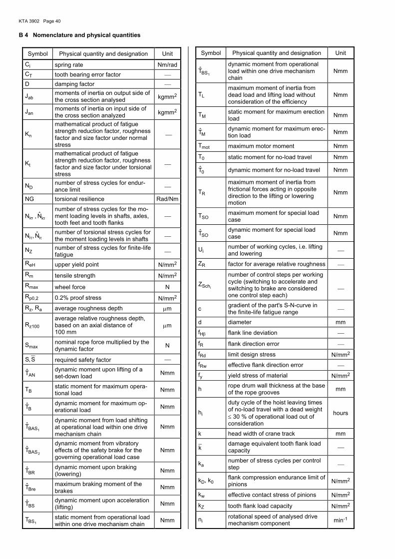
KTA 3902 Page 40
B 4 Nomenclature and physical quantities
Symbol Physical quantity and designation Unit
Ci spring rate Nm/rad
CT tooth bearing error factor
D damping factor
Jab moments of inertia on output side of the cross section analysed kgmm2
Jan moments of inertia on input side of the cross section analyzed kgmm2
Kn
mathematical product of fatigue strength reduction factor, roughness factor and size factor under normal stress
Kt
mathematical product of fatigue strength reduction factor, roughness factor and size factor under torsional stress
ND number of stress cycles for endur-ance limit
NG torsional resilience Rad/Nm
Niσ , σiN̂ number of stress cycles for the mo-ment loading levels in shafts, axles, tooth feet and tooth flanks
Niτ, τiN̂ number of torsional stress cycles for the moment loading levels in shafts
NZ number of stress cycles for finite-life fatigue
ReH upper yield point N/mm2
Rm tensile strength N/mm2
Rmax wheel force N
Rp0,2 0.2% proof stress N/mm2
Rz, Ra average roughness depth µm
Rz100 average relative roughness depth, based on an axial distance of 100 mm
µm
Smax nominal rope force multiplied by the dynamic factor
N
S,S required safety factor
ANT̂ dynamic moment upon lifting of a set-down load
Nmm
TB static moment for maximum opera-tional load
Nmm
BT̂
dynamic moment for maximum op-erational load
Nmm
1BAST̂ dynamic moment from load shifting at operational load within one drive mechanism chain
Nmm
2BAST̂ dynamic moment from vibratory effects of the safety brake for the governing operational load case
Nmm
BRT̂ dynamic moment upon braking (lowering)
Nmm
BreT̂ maximum braking moment of the brakes
Nmm
BST̂ dynamic moment upon acceleration (lifting)
Nmm
1BST static moment from operational load within one drive mechanism chain
Nmm
Symbol Physical quantity and designation Unit
1BST̂ dynamic moment from operational load within one drive mechanism chain
Nmm
TL maximum moment of inertia from dead load and lifting load without consideration of the efficiency
Nmm
TM static moment for maximum erection load
Nmm
MT̂ dynamic moment for maximum erec-tion load
Nmm
Tmot maximum motor moment Nmm
T0 static moment for no-load travel Nmm
0T̂ dynamic moment for no-load travel Nmm
TR
maximum moment of inertia from frictional forces acting in opposite direction to the lifting or lowering motion
Nmm
TSO maximum moment for special load case
Nmm
SOT̂ dynamic moment for special load case
Nmm
Ui number of working cycles, i.e. lifting and lowering
ZR factor for average relative roughness
iSchZ
number of control steps per working cycle (switching to accelerate and switching to brake are considered one control step each)
c gradient of the part's S-N-curve in the finite-life fatigue range
d diameter mm
fHβ flank line deviation
fR flank direction error
fRd limit design stress N/mm2
fRw effective flank direction error
fy yield stress of material N/mm2
h rope drum wall thickness at the base of the rope grooves
mm
hi
duty cycle of the hoist leaving times of no-load travel with a dead weight ≤ 30 % of operational load out of consideration
hours
k head width of crane track mm
k damage equivalent tooth flank load capacity
ka number of stress cycles per control step
kD, k0 flank compression endurance limit of pinions N/mm2
kw effective contact stress of pinions N/mm2
kZ tooth flank load capacity N/mm2
ni rotational speed of analysed drive mechanism component min-1

KTA 3902 Page 41
Symbol Physical quantity and designation Unit
pmaxH contact Hertzian stress N/mm2
pzul allowable contact stress for parallel keys
N/mm2
r1 radius of curvature of track head mm
s rope groove pitch mm
is average path as the sum of lifting and lowering in one working cycle
m
it̂ total duration of oscillations in one working cycle taking the control swit-chings for positioning into account
s
vh,max maximum steady hoisting speed m/s
iv average hoisting speed m/s
yK life time factor for tooth flank load capacity
yG, yH
coefficient in accordance with Ta-ble 121/1 of [2] taking, however, the materials under Table B 1-4 into account
yR roughness factor
yS coefficient in accordance with Ta-ble 121/1 of [2]
yV coefficient in accordance with Ta-ble 121/1 of [2]
yσ life time factor for tooth foot load capacity
nkα stress concentration factor for nor-mal stresses
tkα stress concentration factor for tor-sional stresses
αL load introduction factor
γ angle of inclination of the part's stress-number diagram in the finite-life fatigue range
γm general resistance factor
γmf fatigue strength specific resistance factor
γn risk coefficient
γp partial safety factor
γsm specific resistance factor for material
γss specific resistance factor of slip-resistance connection
ε number of torsional stress cycles due to one control switching
µ0 coefficient of friction
ν, ν required safety factor
ρred equivalent radius of curvature at the pitch point
mm
σ damage-equivalent tensile stress, calculated from the load cycles in Case A and Case B
N/mm2
1BASσ̂
maximum stress due to dynamic moment from load shifting at opera-tional load within one drive mecha-nism chain
N/mm2
Symbol Physical quantity and designation Unit
2BASσ̂
maximum stress due to dynamic moment from vibratory effects of the safety brake for the governing load case
N/mm2
σD, σ0 endurance limit for normal stresses or tooth foot N/mm2
σF effective stress at tooth foot N/mm2
σFE nominal strength at tooth foot N/mm2
σH effective stress at tooth flank N/mm2
σFG endurance strength and static strength at tooth foot N/mm2
σHG endurance strength and static strength at tooth flank N/mm2
σH lim endurance limit for pitting N/mm2
σn endurance limit for normal stresses of material test specimen at 50 % survival probability
N/mm2
∆σRd limit design stress range (normal) N/mm2
∆σSd design stress range (normal) N/mm2
σw effective tooth foot stress N/mm2
σZ tooth foot load capacity N/mm2
1BASVσ̂
maximum equivalent stress due to dynamic moment from load shifting at operational load within one drive mechanism chain
N/mm2
2BASVσ̂
maximum equivalent stress due to dynamic moment from vibratory effects of the safety brake for the governing load case
N/mm2
1BASτ̂
maximum torsional stress due to dynamic moment from load shifting at operational load within one drive mechanism chain
N/mm2
$τBAS2
maximum torsional stress due to dynamic moment from vibratory effects of the safety brake for the governing load case
N/mm2
τ damage-equivalent torsional stress, calculated from the load cycles in Case A and Case B
N/mm2
τD endurance limit for torsional stresses N/mm2
τSt torsional yield point σx
3 N/mm2
τt endurance limit for torsional stresses of material test specimen at 50 % survival probability
N/mm2
Φ2 Dynamic factor on lifting load when hoisting an unrestrained grounded load
ϕS vibration coefficient that takes the dynamic effect due to sudden change in moment into account
ψ dynamic factor
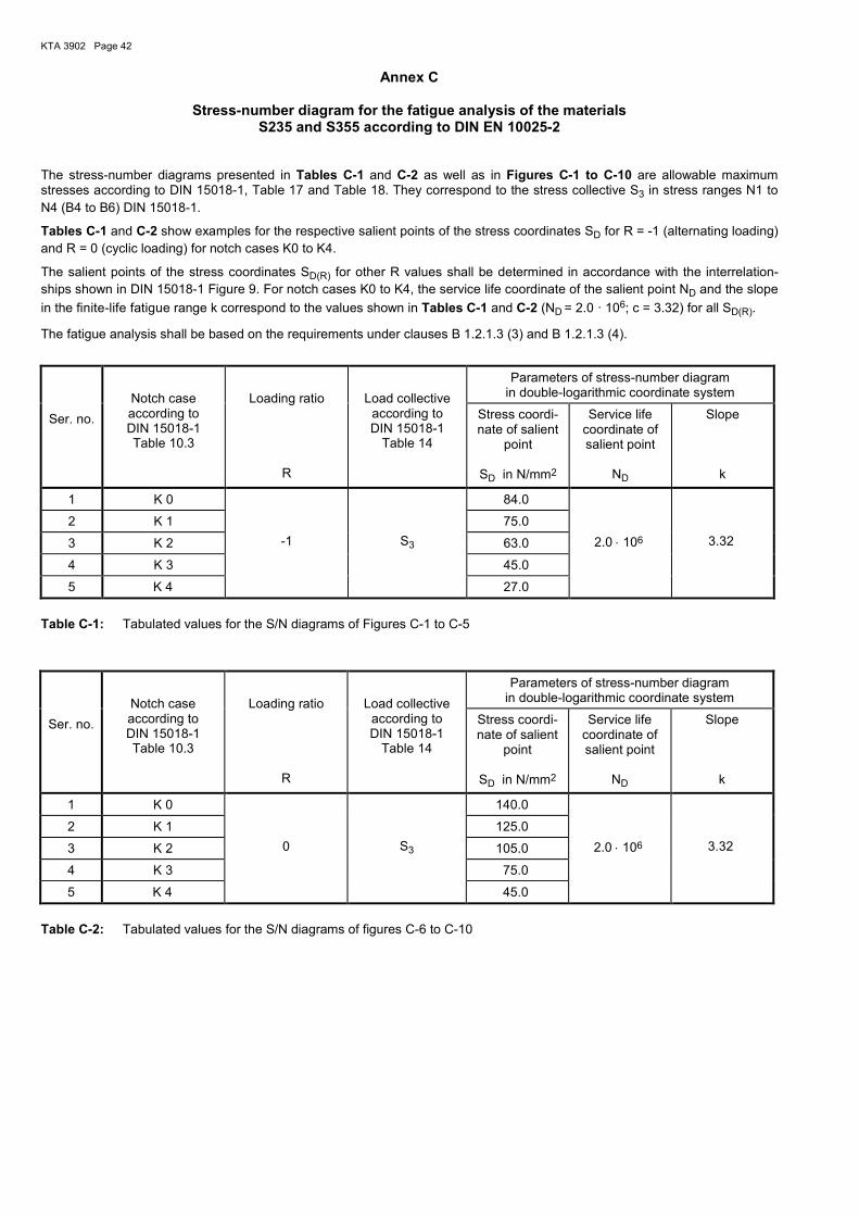
KTA 3902 Page 42
Annex C
Stress-number diagram for the fatigue analysis of the materials S235 and S355 according to DIN EN 10025-2
The stress-number diagrams presented in Tables C-1 and C-2 as well as in Figures C-1 to C-10 are allowable maximum stresses according to DIN 15018-1, Table 17 and Table 18. They correspond to the stress collective S3 in stress ranges N1 to
N4 (B4 to B6) DIN 15018-1.
Tables C-1 and C-2 show examples for the respective salient points of the stress coordinates SD for R = -1 (alternating loading) and R = 0 (cyclic loading) for notch cases K0 to K4.
The salient points of the stress coordinates SD(R) for other R values shall be determined in accordance with the interrelation-ships shown in DIN 15018-1 Figure 9. For notch cases K0 to K4, the service life coordinate of the salient point ND and the slope
in the finite-life fatigue range k correspond to the values shown in Tables C-1 and C-2 (ND = 2.0 · 106; c = 3.32) for all SD(R).
The fatigue analysis shall be based on the requirements under clauses B 1.2.1.3 (3) and B 1.2.1.3 (4).
Ser. no.
Notch case according to DIN 15018-1 Table 10.3
Loading ratio
R
Load collective according to DIN 15018-1
Table 14
Parameters of stress-number diagram in double-logarithmic coordinate system
Stress coordi-nate of salient
point
SD in N/mm2
Service life coordinate of salient point
ND
Slope k
1 K 0
-1
S3
84.0
2.0 ⋅ 106
3.32
2 K 1 75.0
3 K 2 63.0
4 K 3 45.0
5 K 4 27.0
Table C-1: Tabulated values for the S/N diagrams of Figures C-1 to C-5
Ser. no.
Notch case according to DIN 15018-1 Table 10.3
Loading ratio
R
Load collective according to DIN 15018-1
Table 14
Parameters of stress-number diagram in double-logarithmic coordinate system
Stress coordi-nate of salient
point
SD in N/mm2
Service life coordinate of salient point
ND
Slope k
1 K 0
0
S3
140.0
2.0 ⋅ 106
3.32
2 K 1 125.0
3 K 2 105.0
4 K 3 75.0
5 K 4 45.0
Table C-2: Tabulated values for the S/N diagrams of figures C-6 to C-10

KTA 3902 Page 43
76
2
64
1
1
3
4
2
5
O z
ul
Number of load cycles10
S
2 ·
8.4 ·10
Max
imum
str
ess
10
10
N
[N/m
m
]
10
10 1010 10 2 · 10
Figure C-1: S/N diagram for notch case K 0 according to DIN 15018-1, R = -1
76
2
64
1
1
3
4
2
5
O z
ul
Number of load cycles10
S
2 ·
7.5 ·10
Max
imum
str
ess
10
10
N
[N/m
m
]
10
10 1010 10 2 · 10
Figure C-2: S/N diagram for notch case K 1 according to DIN 15018-1, R = -1

KTA 3902 Page 44
76
2
64
1
1
3
4
2
5
O z
ul
Number of load cycles10
S
2 ·
6.3 ·10
Max
imum
str
ess
10
10
N
[N/m
m
]
10
10 1010 10 2 · 10
Figure C-3: S/N diagram for notch case K 2 according to DIN 15018-1, R = -1
76
2
64
1
1
3
4
2
5
O z
ul
Number of load cycles10
S
2 ·
4.5 ·10
Max
imum
str
ess
10
10
N
[N/m
m
]
10
10 1010 10 2 · 10
Figure C-4: S/N diagram for notch case K 3 according to DIN 15018-1, R = -1

KTA 3902 Page 45
76
2
64
1
1
3
4
2
5
O z
ul
Number of load cycles10
S
2 ·
2.7 ·10
Max
imum
str
ess
10
10
N
[N/m
m
]
10
10 1010 10 2 · 10
Figure C-5: S/N diagram for notch case K 4 according to DIN 15018-1, R = -1
76
2
64
2
1
3
4
2
5
O z
ul
1010
S
2 ·
1.4 ·10
Max
imum
str
ess
Number of load cycles
10
N
[N/m
m
]
10
10 1010 10 2 · 10
Figure C-6: S/N diagram for notch case K 0 according to DIN 15018-1, R = 0

KTA 3902 Page 46
76
2
64
2
1
3
4
2
5
O z
ul
1010
S
2 ·
1.25 ·10
Max
imum
str
ess
Number of load cycles
10
N
[N/m
m
]
10
10 1010 10 2 · 10
Figure C-7: S/N diagram for notch case K 1 according to DIN 15018-1, R = 0
76
2
64
2
1
3
4
2
5
O z
ul
1010
S
2 ·
1.05 ·10
Max
imum
str
ess
Number of load cycles
10
N
[N/m
m
]
10
10 1010 10 2 · 10
Figure C-8: S/N diagram for notch case K 2 according to DIN 15018-1, R = 0

KTA 3902 Page 47
76
2
64
1
1
3
4
2
5
O z
ul
Number of load cycles10
S
2 ·
7.5 ·10
Max
imum
str
ess
10
10
N
[N/m
m
]
10
10 1010 10 2 · 10
Figure C-9: S/N diagram for notch case K 3 according to DIN 15018-1, R = 0
76
2
64
1
1
3
4
2
5
O z
ul
Number of load cycles10
S
2 ·
4.5 ·10
Max
imum
str
ess
10
10
N
[N/m
m
]
10
10 1010 10 2 · 10
Figure C-10: S/N diagram for notch case K 4 according to DIN 15018-1, R = 0
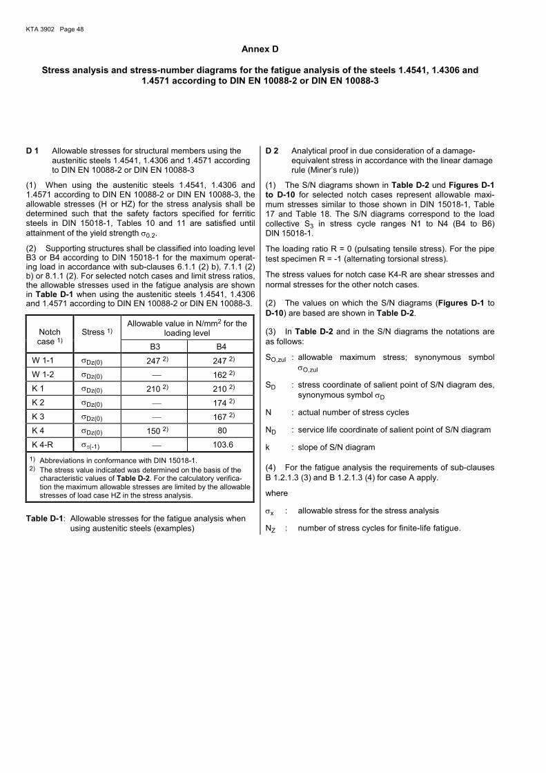
KTA 3902 Page 48
Annex D
Stress analysis and stress-number diagrams for the fatigue analysis of the steels 1.4541, 1.4306 and 1.4571 according to DIN EN 10088-2 or DIN EN 10088-3
D 1 Allowable stresses for structural members using the
austenitic steels 1.4541, 1.4306 and 1.4571 according to DIN EN 10088-2 or DIN EN 10088-3
(1) When using the austenitic steels 1.4541, 1.4306 and 1.4571 according to DIN EN 10088-2 or DIN EN 10088-3, the allowable stresses (H or HZ) for the stress analysis shall be determined such that the safety factors specified for ferritic steels in DIN 15018-1, Tables 10 and 11 are satisfied until attainment of the yield strength σ0.2.
(2) Supporting structures shall be classified into loading level B3 or B4 according to DIN 15018-1 for the maximum operat-ing load in accordance with sub-clauses 6.1.1 (2) b), 7.1.1 (2) b) or 8.1.1 (2). For selected notch cases and limit stress ratios, the allowable stresses used in the fatigue analysis are shown in Table D-1 when using the austenitic steels 1.4541, 1.4306 and 1.4571 according to DIN EN 10088-2 or DIN EN 10088-3.
Notch case 1)
Stress 1)
Allowable value in N/mm2 for the loading level
B3 B4
W 1-1 σDz(0) 247 2) 247 2)
W 1-2 σDz(0) 162 2)
K 1 σDz(0) 210 2) 210 2)
K 2 σDz(0) 174 2)
K 3 σDz(0) 167 2)
K 4 σDz(0) 150 2) 80
K 4-R στ(-1) 103.6
1) Abbreviations in conformance with DIN 15018-1. 2) The stress value indicated was determined on the basis of the
characteristic values of Table D-2. For the calculatory verifica-tion the maximum allowable stresses are limited by the allowable stresses of load case HZ in the stress analysis.
Table D-1: Allowable stresses for the fatigue analysis when using austenitic steels (examples)
D 2 Analytical proof in due consideration of a damage-equivalent stress in accordance with the linear damage rule (Miner’s rule))
(1) The S/N diagrams shown in Table D-2 und Figures D-1 to D-10 for selected notch cases represent allowable maxi-mum stresses similar to those shown in DIN 15018-1, Table 17 and Table 18. The S/N diagrams correspond to the load collective S3 in stress cycle ranges N1 to N4 (B4 to B6) DIN 15018-1.
The loading ratio R = 0 (pulsating tensile stress). For the pipe test specimen R = -1 (alternating torsional stress).
The stress values for notch case K4-R are shear stresses and normal stresses for the other notch cases.
(2) The values on which the S/N diagrams (Figures D-1 to D-10) are based are shown in Table D-2.
(3) In Table D-2 and in the S/N diagrams the notations are as follows:
SO,zul : allowable maximum stress; synonymous symbol σO,zul
SD : stress coordinate of salient point of S/N diagram des, synonymous symbol σD
N : actual number of stress cycles
ND : service life coordinate of salient point of S/N diagram
k : slope of S/N diagram
(4) For the fatigue analysis the requirements of sub-clauses B 1.2.1.3 (3) and B 1.2.1.3 (4) for case A apply.
where
σx : allowable stress for the stress analysis
NZ : number of stress cycles for finite-life fatigue.

KTA 3902 Page 49
Load collec-tive acc. to
DIN 15018-1 Table 14
Parameters of stress-number diagram in double-logarithmic coordinate system
Designation Notch case 1)
Loading ratio
R
Stress coordi-nate of salient
point
SD in N/mm2
Service life coordinate of salient point
ND
Slope
k
Scope of application according to [14]
Perforated bar, Kt = 2.4
W 1-1 2) -1
S3
138.9 1.32 ⋅ 106 13.00 1.0 ⋅ 105 < N ≤ 1.32 ⋅ 106
Perforated bar, Kt = 2.4 W 1-1 2) 0 180.0 1.81 ⋅ 106 6.96 1.0 ⋅ 105 < N ≤ 1.81 ⋅ 106
Perforated bar, Kt = 4.2
W 1-2 2) 0 104.3 6.58 ⋅ 106 7.93 1.0 ⋅ 105 < N ≤ 6.58 ⋅ 106
Butt joint K 1 -1 96.1 2.54 ⋅ 106 6.99 1.0 ⋅ 105 < N ≤ 2.54 ⋅ 106
Butt joint K 1 0 145.9 2.20 ⋅ 107 12.98 1.0 ⋅ 105 < N ≤ 1.00 ⋅ 107
Cruciform joint, double-bevel butt weld, special quality
K 2 2)
0
101.5
5.58 ⋅ 106
6.19
1.0 ⋅ 105 < N ≤ 5.58 ⋅ 106
Cruciform joint double-bevel butt weld, normal quality
K 3
0
88.8
2.32 ⋅ 107
7.51
1.0 ⋅ 105 < N ≤ 1.00 ⋅ 107
Cruciform joint, fillet weld
K 4 -1 20.2 8.14 ⋅ 106 2.89 1.0 ⋅ 105 < N ≤ 8.14 ⋅ 106
Cruciform joint, fillet weld
K 4 0 29.4 1.01 ⋅ 107 3.91 1.0 ⋅ 105 < N ≤ 1.00 ⋅ 107
Pipe test specimen, fillet weld
K 4-R 3) -1 34.8 1.32 ⋅ 107 3.84 1.0 ⋅ 105 < N ≤ 1.00 ⋅ 107
1) Abbreviations in accordance with DIN 15018-1 section 10.3. 2) For notch cases W 1-1, W 1-2 and K 2 the following applies: at N > ND is SO,zul = SD 3) The stress values for K 4-R are shear stresses
Table D-2: Tabulated values for the S/N diagrams of figures D-1 to D-10

KTA 3902 Page 50
4 5
2
4
2
66 7
2O
zul
10
Max
imum
str
ess
10 101.32 ·
Number of load cycles
10
1.389 ·
2
N
10
2
10
[N/m
m
]S
1010
5
2 ·
Figure D-1: S/N diagram for notch case W 1-1 (perforated bar, Kt = 2.4), R = -1
74
2
5 64
2
6
2O
zul
1010
4
10
101.8 ·
1.81 ·
3
5
[N/m
m
]
10
Number of load cycles
Max
imum
str
ess
S
2 · 10 10
2
N
10
Figure D-2: S/N diagram for notch case W 1-1 (perforated bar, Kt = 2.4), R = 0
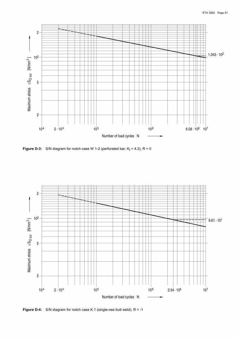
KTA 3902 Page 51
4 5
2
4
2
66 7
2O
zul
1.043 ·
Max
imum
str
ess
10 10
Number of load cycles
106.58 ·
10
2
N
10
2
10
[N/m
m
]S
1010
5
2 ·
Figure D-3: S/N diagram for notch case W 1-2 (perforated bar, Kt = 4.2), R = 0
5
2
2
4
1
4 76 6
O z
ul
2.54 ·10 10 10102 · 10
S 5
[N/m
m
]
Number of load cycles
2
Max
imum
str
ess
10
10
9.61 ·10
2
N
Figure D-4: S/N diagram for notch case K 1 (single-vee butt weld), R = -1
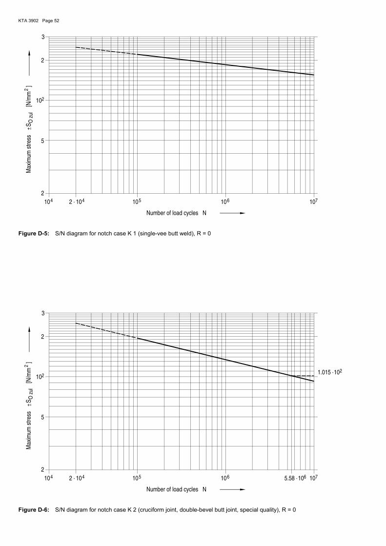
KTA 3902 Page 52
5
2
2
4 4 76
O z
ul
2 ·
3
10 1010 10
S
5
Max
imum
str
ess
Number of load cycles
2
N
10
2
[N/m
m
]
10
Figure D-5: S/N diagram for notch case K 1 (single-vee butt weld), R = 0
4 5
2
4
2
66 7
2O
zul
101.015 ·
10
Max
imum
str
ess
10
3
Number of load cycles
2
5.58 ·10
N
10
2
10
[N/m
m
]S
1010
5
2 ·
Figure D-6: S/N diagram for notch case K 2 (cruciform joint, double-bevel butt joint, special quality), R = 0
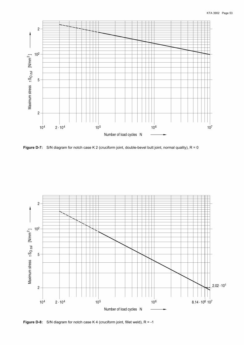
KTA 3902 Page 53
5
2
2
44 6 7
O z
ul
102 · 10 101010
Max
imum
str
ess
S
Number of load cycles
2
5
2
N
[N/m
m
] 10
Figure D-7: S/N diagram for notch case K 2 (cruciform joint, double-bevel butt joint, normal quality), R = 0
4 5
2
4
1
66 7
2O
zul
2.02 ·
Max
imum
str
ess
10 1010
Number of load cycles
8.14 ·
102
N
10
2
10
[N/m
m
]S
1010
5
2 ·
Figure D-8: S/N diagram for notch case K 4 (cruciform joint, fillet weld), R = -1

KTA 3902 Page 54
5
2
2
44 6 7
O z
ul
102 · 10 101010
Max
imum
str
ess
S
Number of load cycles
2
5
2
N
[N/m
m
] 10
Figure D-9: S/N diagram for notch case K 4 (cruciform joint, fillet weld), R = 0
5
2
2
44 6 7
O z
ul
102 · 10 101010
Max
imum
str
ess
S
Number of load cycles
2
5
2
N
[N/m
m
] 10
Figure D-10: S/N diagram for notch case K 4-R (pipe test specimen, fillet weld), R = -1

KTA 3902 Page 55
Annex E
Required Performance Levels according to DIN EN ISO 13849-1 for function of safety-related parts of control systems
E 1 General
(1) When applying the requirements according to DIN EN ISO 13849-1 on functions of safety-related parts of control systems in lifting equipment which has to meet the require-ments of KTA 3902, sections 4.2, 4.3 or 4.4, the following general principles shall apply:
a) The requirements specified in Table E-1 shall apply irre-spective of the demand rate mentioned in the scope of DIN EN ISO 13849-1.
b) Deviating from the stipulations in section 4.3 of DIN EN ISO 13849-1, the required Performance Levels (PL) shall be determined in accordance with the criteria laid down in section E 2.
E 2 Classification scheme
(1) Performance Level “a“ according to DIN EN ISO 13849-1 is required for operational functions which are of certain safe-ty-related relevance, e.g. if their reliability influences the re-sponse frequency of functions for which PL “b”, “c”, “d” or “e” is required.
(2) Performance Level “b“ according to DIN EN ISO 13849-1 is required for operational functions which are of indirect safe-ty-related relevance, e.g. which support the safe operation of lifting equipment (e.g. monitoring of direction of rotation, standstill monitoring, safety-relevant information systems).
(3) Performance Level “c” according to DIN EN ISO 13849-1 is required for safety functions,
a) which are intended to master such operational troubles where the dangerous conditions described in section 4.2 are to be expected, and which are capable of limiting or avoiding such risk (e.g. by manual intervention),
b) which are integrated upstream of the functions of PL “d“ or “e“.
(4) Performance Level “d“ according to DIN EN ISO 13849-1 is required for safety functions which are intended to master operational troubles, and where
a) the dangerous conditions as described under section 4.2 are to be expected and no other possibilities of avoiding such danger or limiting the effects of damage (e.g. by manual intervention) exist,
b) the dangers as described under sections 4.3 or 4.4 are to be expected and possibilities of avoiding such danger or limiting the effects of damage (e.g. by manual intervention) exist.
(5) Performance Level “e“ according to DIN EN ISO 13849-1 is required for safety functions which are intended to master operational troubles where the dangerous conditions as de-scribed under sections 4.3 or 4.4 are to be expected and no other possibilities of avoiding such danger or limiting the ef-fects of damage (e.g. by manual intervention) exist.
For safety functions where in case of their failure an event beyond accident planning reference levels of §§ 104 of the Radiation Protection Ordinance is to be assumed and where the function is to be provided by means of software-based systems, the functions shall be of redundant design with one function being classified in PL “e” and one function being in-dependent of the other and of different design to be at least classified in Performance Level “c“.
E 3 Required Performance Levels according to DIN EN ISO 13849-1 for functions of safety-related parts of control systems according to KTA 3902, sections 4.2, 4.3 or 4.4
(1) The typical functions of safety-related parts of control systems in lifting equipment according to KTA 3902, sections 4.2, 4.3 or 4.4 are assigned in Table E-1 to Performance Lev-els which satisfy the criteria of section E 2.
N o t e :
See sub-clause 6.5.1 (3) as regards the application of “Safety In-tegrity Levels” (SIL) specified in the DIN EN standard series 61508 instead of the Performance Levels according to DIN EN ISO 13849-1 laid down in Table E-1.
(2) Deviations from the design requirements laid down in Table E-1 shall be justified in each individual case.
Ser. No.
Function
Requirement according to KTA 3902,
clause
Performance Level acc. to DIN EN ISO 13849-1 when classifying lifting equipment acc. to KTA 3902, section
Note
4.2 4.3 4.4
General:
1. Switch on/off of lifting equipment, release from control room
6.5.2 (1), 8.5 b) a a a
2. Emergency-off 6.5.4.1 (5) d d d For wireless control sys-tems: “Stop“
3. Emergency-off switch for the supervising person when applying the “four-eyes principle“
6.5.4.1 (6) d d 1) For wireless control sys-tems: “Stop“
4. Reporting, warning and alarm signals 6.5.4.2 a a a
1) This function is not required, since the absence of this function does not lead to inadmissible safety-related effects.
Table E-1: Assignment of typical functions of safety-related parts of control systems in lifting equipment according to sections 4.2 to 4.4 to the required Performance Levels according to DIN EN ISO 13849-1

KTA 3902 Page 56
Ser. No.
Function
Requirement according to KTA 3902,
clause
Performance Level acc. to DIN EN ISO 13849-1 when classifying lifting equipment acc. to KTA 3902, section
Note
4.2 4.3 4.4
5.
Operational status messages signalling such conditions as are triggered by safety-related activities or from which safety-related activities are derived
6.5.4.2 b b b e.g. check-back signal of load limit transition switch
6. Operational functions and drive control 6.5.4.1 a a a
e.g. control functions of master controller, mode selector switch for control commands for drive con-trol system (e.g. set point signals)
7. Running time or load collective meter for engagement of safety brake
6.5.2 (5), 7.5 b) a a a
8. Mutual interlocking of control points 6.5.4.1 (7) a a a
The emergency-off switch shall also be effective at switched-off control points (except for: stop function on wireless controls).
9. Phase-sequence relays and a phase con-ductor monitor
6.5.2 (2) a a a
10. Overload protective devices for motors 6.5.2 (3) a a a
Hoists and lateral transport drives:
11. Speed limiters at travelling and hoist end positions
6.5.3 (5) a a a
12.
a) Switch-off if allowable speed at travel-ling end position is exceeded
6.5.3 (5) c c d
b) Switch-off if allowable speed at hoist end is exceeded
6.5.3 (5), 7.5
For examples see Figures E-1 and E-4. First switch-off device d e e
Second switch-off device 1) 2) c 2)
13. Operational travel limiters 6.5.3 (1) and (3) a a a
Switch-off at operationally allowable lateral transport drive or hoist end posi-tions
14. Safety travel limiters of lateral transport drives
6.5.3 (1) c c d
15. Standstill monitoring 6.5.2 (8) b b b
16. Enforced zero position 6.5.4.1 (1) a a a
17. Monitoring of direction during start-up from standstill in case of converter drives
6.5.2 (8) b b b
18. Interlocking of lateral transport drive and hoist movements
6.5.3 (6) c c 3)
19. Interlocking of lateral transport drive and hoist movement as well as limitation of lateral movement
8.5 a), 8.5 f), 8.5 g), 8.5 l) 3) 3) d
1) Only if, in case of failure of this function, an event beyond the accident planning reference levels of §§ 104 of the Radiation Protection Ordinance is to be assumed and the function is to be provided by means of software-based systems.
2) This function is not required, since the absence of this function does not lead to inadmissible safety-related effects.
3) This function is irrelevant due to technical reasons. The requirements are fulfilled by another function.
Table E-1: Assignment of typical functions of safety-related parts of control systems in lifting equipment according to sections 4.2 to 4.4 to the required Performance Levels according to DIN EN ISO 13849-1 (continued)
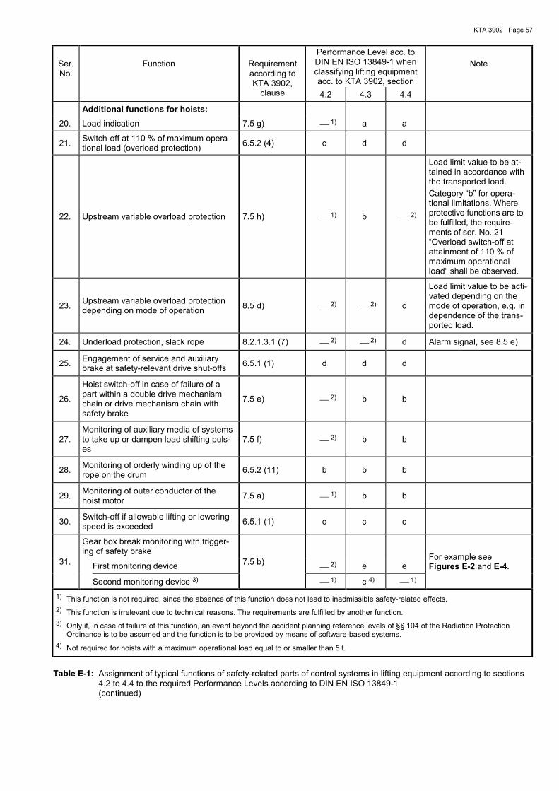
KTA 3902 Page 57
Ser. No.
Function
Requirement according to KTA 3902,
clause
Performance Level acc. to DIN EN ISO 13849-1 when classifying lifting equipment acc. to KTA 3902, section
Note
4.2 4.3 4.4
Additional functions for hoists:
20. Load indication 7.5 g) 1) a a
21. Switch-off at 110 % of maximum opera-tional load (overload protection)
6.5.2 (4) c d d
22. Upstream variable overload protection 7.5 h) 1) b 2)
Load limit value to be at-tained in accordance with the transported load.
Category “b” for opera-tional limitations. Where protective functions are to be fulfilled, the require-ments of ser. No. 21 “Overload switch-off at attainment of 110 % of maximum operational load“ shall be observed.
23. Upstream variable overload protection depending on mode of operation
8.5 d) 2) 2) c
Load limit value to be acti-vated depending on the mode of operation, e.g. in dependence of the trans-ported load.
24. Underload protection, slack rope 8.2.1.3.1 (7) 2) 2) d Alarm signal, see 8.5 e)
25. Engagement of service and auxiliary brake at safety-relevant drive shut-offs
6.5.1 (1) d d d
26.
Hoist switch-off in case of failure of a part within a double drive mechanism chain or drive mechanism chain with safety brake
7.5 e) 2) b b
27. Monitoring of auxiliary media of systems to take up or dampen load shifting puls-es
7.5 f) 2) b b
28. Monitoring of orderly winding up of the rope on the drum
6.5.2 (11) b b b
29. Monitoring of outer conductor of the hoist motor
7.5 a) 1) b b
30. Switch-off if allowable lifting or lowering speed is exceeded
6.5.1 (1) c c c
31.
Gear box break monitoring with trigger-ing of safety brake
7.5 b)
For example see Figures E-2 and E-4. First monitoring device 2) e e
Second monitoring device 3) 1) c 4) 1)
1) This function is not required, since the absence of this function does not lead to inadmissible safety-related effects.
2) This function is irrelevant due to technical reasons. The requirements are fulfilled by another function.
3) Only if, in case of failure of this function, an event beyond the accident planning reference levels of §§ 104 of the Radiation Protection Ordinance is to be assumed and the function is to be provided by means of software-based systems.
4) Not required for hoists with a maximum operational load equal to or smaller than 5 t.
Table E-1: Assignment of typical functions of safety-related parts of control systems in lifting equipment according to sections 4.2 to 4.4 to the required Performance Levels according to DIN EN ISO 13849-1 (continued)
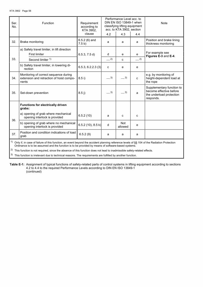
KTA 3902 Page 58
Ser. No.
Function
Requirement according to KTA 3902,
clause
Performance Level acc. to DIN EN ISO 13849-1 when classifying lifting equipment acc. to KTA 3902, section
Note
4.2 4.3 4.4
32. Brake monitoring 6.5.2 (6) and 7.5 b)
a a a Position and brake lining thickness monitoring
33.
a) Safety travel limiter, in lift direction
6.5.3, 7.5 d)
For example see Figures E-3 and E-4.
First limiter d e e
Second limiter 1) 2) c 2)
b) Safety travel limiter, in lowering di-rection
6.5.3, 6.2.2.3 (3) c e e
34. Monitoring of correct sequence during extension and retraction of hoist compo-nents
8.5 i) 3) 3) c e.g. by monitoring of height-dependent load at the rope
35. Set-down prevention 8.5 j) 3) 3) a
Supplementary function to become effective before the underload protection responds.
Functions for electrically driven grabs:
36.
a) opening of grab where mechanical opening interlock is provided
6.5.2 (10) a c c
b) opening of grab where no mechanical opening interlock is provided
6.5.2 (10), 8.5 k) d Not
allowed e
37. Position and condition indications of load grab
6.5.2 (9) a a a
1) Only if, in case of failure of this function, an event beyond the accident planning reference levels of §§ 104 of the Radiation Protection Ordinance is to be assumed and the function is to be provided by means of software-based systems.
2) This function is not required, since the absence of this function does not lead to inadmissible safety-related effects.
3) This function is irrelevant due to technical reasons. The requirements are fulfilled by another function.
Table E-1: Assignment of typical functions of safety-related parts of control systems in lifting equipment according to sections 4.2 to 4.4 to the required Performance Levels according to DIN EN ISO 13849-1 (continued)

KT
A 3
902
Pa
ge
59
Motor
Opera
tional
bra
ke
Auxili
ary
bra
ke
Crane switch Q0
Q1Q71Q72
Safety control
Functions:
- creep speed monitoring during lifting
…….
…….
…….
K00
K01
Operational control
Q1 Q71 U01Q72
Opera-tionalbrake
Auxiliarybrake
Convertersafestop
Drivecontactor
K00
*4K02
K01
U01
Safe
ty b
rake
Q71
Frequency relais
K02
Q72
Fu
rth
er
ho
ists
an
d la
tera
ltr
an
sp
ort
drive
s
*1Q1
Q0
*3*2
*2
*4*3
*1
Testing
Testing
Q0
Q71
K22
K21
Tra
nsm
issio
n
Figure E-1: Example for realization of the requirements specified in Table E-1 for the function ser. no. 12b “Switch-off in case of excess of allowable speed at hoist end” in lifting equip-ment according to sections 4.3 or 4.4 (Example for hoist with single drive mechanism chain and insufficient travel stop way length upwards upon response of safety travel limiter)
Requirements to DIN EN ISO 13849-1 for
Performance Level “e” and category 4
Requirements to DIN EN ISO 13849-1 for
Performance Level “c” and category 2
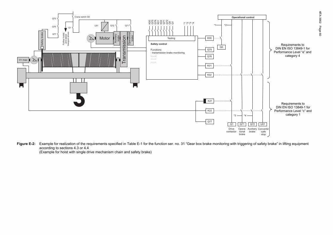
KT
A 3
902
Pa
ge
60
K
Motor
Q1Q71Q72
Safety control
Functions:
- transmission brake monitoring
…….
…….
…….
K00
K01
Q76
K0
0
*4Q76
Q75
U01
Q77
Q75
V> max
Q75
K0
1
K02
K0
2
Q76
*1Q72
Q71
*3*2
*2*1
Q0
Q1
Testing
Q0
Q1 Q71 U01Q72
K22
K21
*4*3
Q77
Safe
ty b
rake
Fu
rth
er
ho
ists
an
d la
tera
ltr
an
sp
ort
drive
s
Crane switch Q0
Auxili
ary
bra
ke
Tra
nsm
issio
nO
pera
tional
bra
ke
Operational control
Opera-tionalbrake
Auxiliarybrake
Convertersafestop
Drivecontactor
Figure E-2: Example for realization of the requirements specified in Table E-1 for the function ser. no. 31 “Gear box brake monitoring with triggering of safety brake” in lifting equipment according to sections 4.3 or 4.4 (Example for hoist with single drive mechanism chain and safety brake)
Requirements to DIN EN ISO 13849-1 for
Performance Level “e” and category 4
Requirements to DIN EN ISO 13849-1 for
Performance Level “c” and category 1

KT
A 3
902
Pa
ge
61
Safety control
Functions:
- safety travel limiter at top
…….
…….
…….
K00
K01
Operational control
K00
*4K02
K01
K02
*1Q74
Q73
*3*2
*2*1
Q0
Q1
Testing
Q0
Motor 1 Motor 2
U01
Q1
Q71 Q72 Q73Q74U02
Q1 Q71 U02U01Q74Q72Q73
K22
K21
*4*3
Q72
Q71
Au
xili
ary
bra
ke
Tra
nsm
issio
nO
pe
ratio
na
lb
rake
Au
xili
ary
bra
ke
Op
era
tio
na
lb
rake
Tra
nsm
issio
nCrane switch Q0
Further hoists and lateral transport drives
Drivecontactor
Operationalbrakes
Auxiliarybrakes
Converterssafe stop
Figure E-3: Example for realization of the requirements specified in Table E-1 for the function ser. no. 33a “Safety travel limiter in lift direction“ in lifting equipment according to sections 4.3 or 4.4 (Example for hoist with double drive mechanism chain and sufficient travel stop path upon response of the safety travel limiter in the main circuit, in lift direction)
Requirements to DIN EN ISO 13849-1 for
Performance Level “c” and category 1
Requirements to DIN EN ISO 13849-1 for
Performance Level “e” and category 4
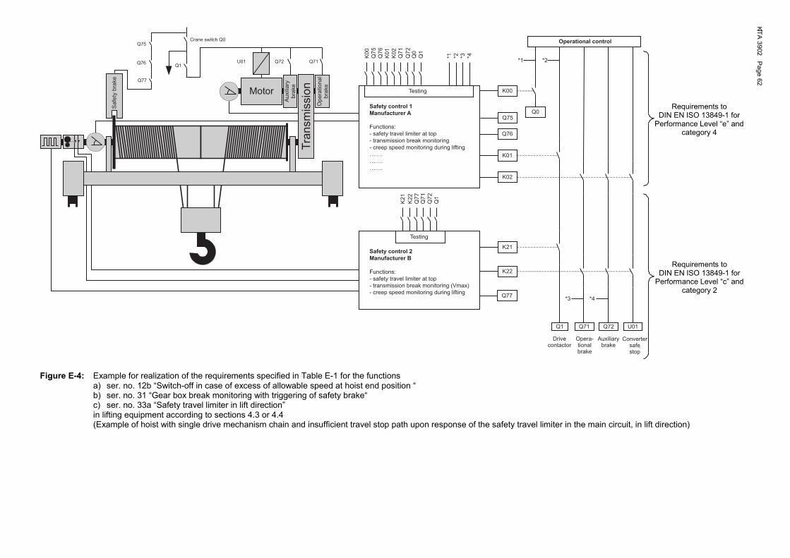
KT
A 3
902
Pa
ge
62
K
Motor
Q71Q72
Safety control 1
Manufacturer A
Functions:
- safety travel limiter at top
- transmission break monitoring
- creep speed monitoring during lifting
…….
…….
…….
K00
K01
Operational control
Q1 Q71 U01Q72
Q76
K00
*4Q7
6
Q7
5
U01
Q75
K01
Safety control 2
Manufacturer B
Functions:
- safety travel limiter at top
- transmission break monitoring (Vmax)
- creep speed monitoring during lifting
K22
K21
Q77
K02
K02
*1Q7
2
Q7
1
*3*2
*2
*4*3
*1
Q0
Q1
Testing
Testing
Q0
K21
Q7
1
Q1
Q7
7
K22
Q7
2
Q1
Q77
Q75
Q76
Crane switch Q0
Sa
fety
bra
ke
Au
xili
ary
bra
ke
Tra
nsm
issio
nO
pe
ratio
na
lb
rake
Opera-tionalbrake
Auxiliarybrake
Convertersafestop
Drivecontactor
Figure E-4: Example for realization of the requirements specified in Table E-1 for the functions a) ser. no. 12b “Switch-off in case of excess of allowable speed at hoist end position “ b) ser. no. 31 “Gear box break monitoring with triggering of safety brake“ c) ser. no. 33a “Safety travel limiter in lift direction” in lifting equipment according to sections 4.3 or 4.4 (Example of hoist with single drive mechanism chain and insufficient travel stop path upon response of the safety travel limiter in the main circuit, in lift direction)
Requirements to DIN EN ISO 13849-1 for
Performance Level “e” and category 4
Requirements to DIN EN ISO 13849-1 for
Performance Level “c” and category 2

KTA 3902 Page 63
Annex F
Regulations and literature referred to in this Safety Standard
(The references exclusively refer to the version given in this annex. Quotations of regulations referred to therein refer to the version available when the individual reference below was established or issued.)
Directive 2014/33/EU Directive 2014/33/EU of the European Parliament and of the Council of February 26, 2014 on the harmonisation of the laws of the Member States relating to lifts and safety components for lifts (recast)
Atomic Energy Act (AtG) Act on the Peaceful Utilization of Atomic Energy and the Protection against its Hazards (Atomic Energy Act) in the Version Promulgated on July 15, 1985 (BGBl. I, p. 1565), most recently changed by article 239 of the Ordinance dated June 19, 2020 (BGBl. I, p. 1328)
StrlSchG Act on the Protection against the Harmful Effect of Ionising Radiation (Radiation Protection Act - StrlSchG) of June 27, 2017 (BGBl. I, p. 1966), most recently changed by Article 5, Sec. 1 of the Act dated October 23, 2020 (BGBl. I p. 2232)
StrlSchV Ordinance on the Protection against the Harmful Effects of Ionising Radiation (Radiation Protection Ordinance - StrlSchV) of November 29, 2018 (BGBl. I, p. 2034, 2036), most re-cently changed by Article 1 of the Ordinance dated November 20, 2020 (BGBl. I p. 2502)
SiAnf (2015-03) Safety Requirements for Nuclear Power Plants (SiAnf) as Promulgated on March 3, 2015 (BAnz AT 30.03.2015 B2)
Interpretations (2015-03) Interpretations of the Safety Requirements for Nuclear Power Plants of November 22, 2012, as Amended on March 3rd, 2015 (BAnz. AT 30.03.2015 B3)
KTA 1401 (2017-11) General Requirements Regarding Quality Assurance
KTA 2201.4 (2012-11) Design of nuclear power plants against seismic events; Part 4: Components
KTA 3201.2 (2017-11) Components of the Reactor Coolant Pressure Boundary of Light Water Reactors; Part 2: Design and analysis
KTA 3205.1 (2018-10) Component Support Structures with Non-Integral Connections; Part 1: Component Support Structures with Non-Integral Connections for Components of the Reactor Coolant Pressure Boundary of Light Water Reactors
KTA 3903 (2020-12) Inspection, testing and operation of lifting equipment in nuclear power plants
DIN EN 81-20 (2014-11) Safety rules for the construction and installation of lifts - Lifts for the transport of persons and goods - Part 20: Passenger and goods passenger lifts; German version EN 81-20:2014
DIN 743-1 (2012-12) Shafts and axles, calculation of load capacity - Part 1: General
DIN 743-2 (2012-12) Shafts and axles, calculation of load capacity - Part 2: Theoretical stress concentration fac-tors and fatigue notch factors
DIN 743-3 (2012-12) Shafts and axles, calculation of load capacity - Part 3: Strength of materials (Corrigendum 2014-12)
DIN EN 818-2 (2008-12) Short link chain for lifting purposes. Safety. Part 2: Medium tolerance chain for chain slings. Grade 8; German version EN 818-2:1996+A1:2008
DIN EN 818-4 (2008-12) Short link chain for lifting purposes – Safety - Part 4: Chain slings - Grade 8; German ver-sion EN 818-4:1996+A1:2008
DIN EN 894-1 (2009-01) Safety of machinery - Ergonomics requirements for the design of displays and control actua-tors – Part 1: General principles for human interactions with displays and control actuators; German version EN 894-1:1997+A1:2008
DIN EN ISO 898-1 (2013-05) Mechanical properties of fasteners made of carbon steel and alloy steel - Part 1: Bolts, screws and studs with specified property classes - Coarse thread and fine pitch thread (ISO 898-1:2013); German version EN ISO 898-1:2013
DIN EN ISO 898-2 (2012-08) Mechanical properties of fasteners made of carbon steel and alloy steel - Part 2: Nuts with specified property classes - Coarse thread and fine pitch thread (ISO 898-2:2012); German version EN ISO 898-2:2012
DIN EN 1090-2 (2018-09) Execution of steel structures and aluminium structures - Part 2: Technical requirements for steel structures; German version EN 1090-2:2018
DIN EN 1677-1 (2009-03) Components for slings. Safety – Part 1: Forged steel components, Grade 8; German version EN 1677-1:2000+A1:2008
DIN EN 1677-2 (2008-06) Components for slings. Safety – Part 2: Forged steel lifting hooks with latch, Grade 8; Ger-man version EN 1677-2:2000+A1:2008 (Correction: 2009-01)
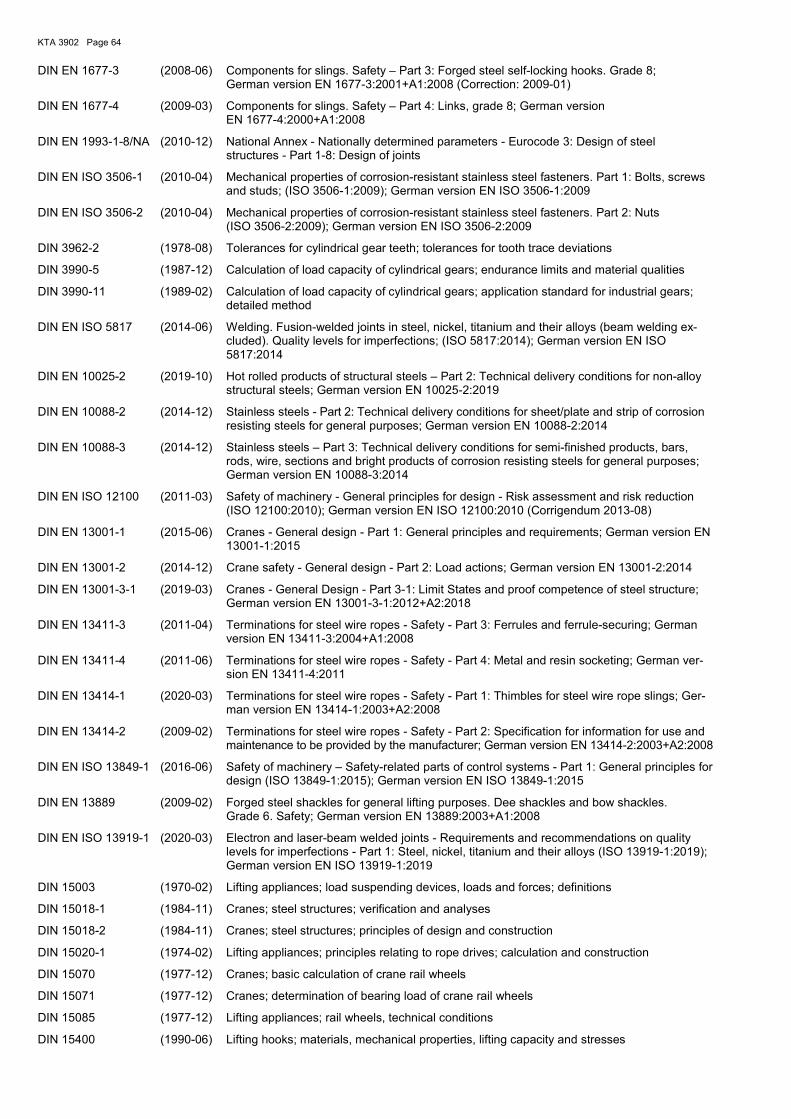
KTA 3902 Page 64
DIN EN 1677-3 (2008-06) Components for slings. Safety – Part 3: Forged steel self-locking hooks. Grade 8; German version EN 1677-3:2001+A1:2008 (Correction: 2009-01)
DIN EN 1677-4 (2009-03) Components for slings. Safety – Part 4: Links, grade 8; German version EN 1677-4:2000+A1:2008
DIN EN 1993-1-8/NA (2010-12) National Annex - Nationally determined parameters - Eurocode 3: Design of steel structures - Part 1-8: Design of joints
DIN EN ISO 3506-1 (2010-04) Mechanical properties of corrosion-resistant stainless steel fasteners. Part 1: Bolts, screws and studs; (ISO 3506-1:2009); German version EN ISO 3506-1:2009
DIN EN ISO 3506-2 (2010-04) Mechanical properties of corrosion-resistant stainless steel fasteners. Part 2: Nuts (ISO 3506-2:2009); German version EN ISO 3506-2:2009
DIN 3962-2 (1978-08) Tolerances for cylindrical gear teeth; tolerances for tooth trace deviations
DIN 3990-5 (1987-12) Calculation of load capacity of cylindrical gears; endurance limits and material qualities
DIN 3990-11 (1989-02) Calculation of load capacity of cylindrical gears; application standard for industrial gears; detailed method
DIN EN ISO 5817 (2014-06) Welding. Fusion-welded joints in steel, nickel, titanium and their alloys (beam welding ex-cluded). Quality levels for imperfections; (ISO 5817:2014); German version EN ISO 5817:2014
DIN EN 10025-2 (2019-10) Hot rolled products of structural steels – Part 2: Technical delivery conditions for non-alloy structural steels; German version EN 10025-2:2019
DIN EN 10088-2 (2014-12) Stainless steels - Part 2: Technical delivery conditions for sheet/plate and strip of corrosion resisting steels for general purposes; German version EN 10088-2:2014
DIN EN 10088-3 (2014-12) Stainless steels – Part 3: Technical delivery conditions for semi-finished products, bars, rods, wire, sections and bright products of corrosion resisting steels for general purposes; German version EN 10088-3:2014
DIN EN ISO 12100 (2011-03) Safety of machinery - General principles for design - Risk assessment and risk reduction (ISO 12100:2010); German version EN ISO 12100:2010 (Corrigendum 2013-08)
DIN EN 13001-1 (2015-06) Cranes - General design - Part 1: General principles and requirements; German version EN 13001-1:2015
DIN EN 13001-2 (2014-12) Crane safety - General design - Part 2: Load actions; German version EN 13001-2:2014
DIN EN 13001-3-1 (2019-03) Cranes - General Design - Part 3-1: Limit States and proof competence of steel structure; German version EN 13001-3-1:2012+A2:2018
DIN EN 13411-3 (2011-04) Terminations for steel wire ropes - Safety - Part 3: Ferrules and ferrule-securing; German version EN 13411-3:2004+A1:2008
DIN EN 13411-4 (2011-06) Terminations for steel wire ropes - Safety - Part 4: Metal and resin socketing; German ver-sion EN 13411-4:2011
DIN EN 13414-1 (2020-03) Terminations for steel wire ropes - Safety - Part 1: Thimbles for steel wire rope slings; Ger-man version EN 13414-1:2003+A2:2008
DIN EN 13414-2 (2009-02) Terminations for steel wire ropes - Safety - Part 2: Specification for information for use and maintenance to be provided by the manufacturer; German version EN 13414-2:2003+A2:2008
DIN EN ISO 13849-1 (2016-06) Safety of machinery – Safety-related parts of control systems - Part 1: General principles for design (ISO 13849-1:2015); German version EN ISO 13849-1:2015
DIN EN 13889 (2009-02) Forged steel shackles for general lifting purposes. Dee shackles and bow shackles. Grade 6. Safety; German version EN 13889:2003+A1:2008
DIN EN ISO 13919-1 (2020-03) Electron and laser-beam welded joints - Requirements and recommendations on quality levels for imperfections - Part 1: Steel, nickel, titanium and their alloys (ISO 13919-1:2019); German version EN ISO 13919-1:2019
DIN 15003 (1970-02) Lifting appliances; load suspending devices, loads and forces; definitions
DIN 15018-1 (1984-11) Cranes; steel structures; verification and analyses
DIN 15018-2 (1984-11) Cranes; steel structures; principles of design and construction
DIN 15020-1 (1974-02) Lifting appliances; principles relating to rope drives; calculation and construction
DIN 15070 (1977-12) Cranes; basic calculation of crane rail wheels
DIN 15071 (1977-12) Cranes; determination of bearing load of crane rail wheels
DIN 15085 (1977-12) Lifting appliances; rail wheels, technical conditions
DIN 15400 (1990-06) Lifting hooks; materials, mechanical properties, lifting capacity and stresses
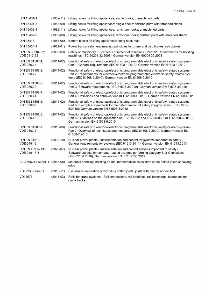
KTA 3902 Page 65
DIN 15401-1 (1982-11) Lifting hooks for lifting appliances; single hooks; unmachined parts
DIN 15401-2 (1983-09) Lifting hooks for lifting appliances; single hooks; finished parts with threaded shank
DIN 15402-1 (1982-11) Lifting hooks for lifting appliances; ramshorn hooks; unmachined parts
DIN 15402-2 (1983-09) Lifting hooks for lifting appliances; ramshorn hooks; finished parts with threaded shank
DIN 15413 (1983-08) Bottom blocks for lifting appliances; lifting hook nuts
DIN 15434-1 (1989-01) Power transmission engineering; principles for drum- and disc brakes, calculation
DIN EN 60204-32; (2009-03) Safety of machinery - Electrical equipment of machines - Part 32: Requirements for hoisting VDE 0113-32 machines (IEC 60204-32:2008); German version EN 60204-32:2008
DIN EN 61508-1; (2011-02) Functional safety of electrical/electronic/programmable electronic safety-related systems - VDE 0803-1 Part 1: General requirements (IEC 61508-1:2010); German version EN 61508-1:2010
DIN EN 61508-2; (2011-02) Functional safety of electrical/electronic/programmable electronic safety-related systems - VDE 0803-2 Part 2: Requirements for electrical/electronic/programmable electronic safety-related sys-
tems (IEC 61508-2:2010); German version EN 61508-2:2010
DIN EN 61508-3; (2011-02) Functional safety of electrical/electronic/programmable electronic safety-related systems - VDE 0803-3 Part 3: Software requirements (IEC 61508-3:2010); German version EN 61508-3:2010
DIN EN 61508-4; (2011-02) Functional safety of electrical/electronic/programmable electronic safety-related systems - VDE 0803-4 Part 4: Definitions and abbreviations (IEC 61508-4:2010); German version EN 61508-4:2010
DIN EN 61508-5; (2011-02) Functional safety of electrical/electronic/programmable electronic safety-related systems - VDE 0803-5 Part 5: Examples of methods for the determination of safety integrity levels (IEC 61508-
5:2010); German version EN 61508-5:2010
DIN EN 61508-6; (2011-02) Functional safety of electrical/electronic/programmable electronic safety-related systems - VDE 0803-6 Part 6: Guidelines on the application of IEC 61508-2 and IEC 61508-3 (IEC 61508-6:2010);
German version EN 61508-6:2010
DIN EN 61508-7; (2013-09) Functional safety of electrical/electronic/programmable electronic safety-related systems - VDE 0803-7 Part 7: Overview of techniques and measures (IEC 61508-7:2010); German version EN
61508-7:2010
DIN EN 61513; (2002-10) Nuclear power plants - Instrumentation and control for systems important to safety - VDE 0491-2 General requirements for systems (IEC 61513:2011); German version EN 61513:2013
DIN EN IEC 62138; (2020-07) Nuclear power plants - Instrumentation and control systems important to safety - VDE 0491-3-3 Software aspects for computer-based systems performing category B or C functions
(IEC 62138:2018); German version EN IEC 62138:2019
SEB 666211 Suppl. 1 (1985-08) Materials handling; hoisting drums; mathematical calculation of the bolted joints of bulldog grips
VDI 2230 Sheet 1 (2015-11) Systematic calculation of high duty bolted joints; joints with one cylindrical bolt
VDI 3576 (2011-03) Rails for crane systems - Rail connections, rail beddings, rail fastenings, tolerances for crane tracks
KTA 3902 Page 66
Literature
[1] Niemann, G. Maschinenelemente Band 1, Springer Verlag Berlin/Göttingen/Heidelberg 1981, 2. Auflage (Mechanical devices Volume 1, Springer Verlag Berlin/Göttingen/Heidelberg 1981 2nd Edition)
[2] Niemann, G. Maschinenelemente Band 2, Springer Verlag Berlin/Göttingen/Heidelberg 1965 (Mechanical devices, Volume 2, Springer Verlag Berlin/Göttingen/Heidelberg 1965)
[3] Hähnchen, R. Dauerfestigkeit für Stahl- und Gußeisen, Carl Hanser Verlag, München 1963 (Endurance strength for steel and cast-iron, Carl Hanser Verlag, München 1963)
[4] Decker, K.-H. Maschinenelemente, Carl Hanser Verlag, München 1982 (Mechanical devices, Carl Hanser Verlag, München, 1982)
[5] Leitfaden für eine Betriebsfestigkeitsrechnung; Empfehlung zur Lebensdauer-abschätzung von Maschinenbauteilen, 4. Auflage, Herausgegeben vom Verein zur Förderung der Forschung und der Anwendung von Betriebsfestigkeits-Kenntnissen in der Eisenhüttenindustrie (VBFEh) im Stahlinstitut VDEh, bearbeitet von Helmut Gude-hus und Harald Zenner, Düsseldorf 1999 (Guideline on the calculation of cyclic strength; recommendations regarding life cycle estimations for machine components, 4th edition; published by the Association for the promotion of research and knowledge of operational strength in metallurgical enginee-ring (VBFEh) at Iron and Steel Instiute VDEh, edited by Helmut Gudehus and Harald Zenner, Düsseldorf 1999
[6] Dubbel, H. u. W. Beitz Taschenbuch für den Maschinenbau, 16. Auflage korrigiert und ergänzt, Springer-Verlag, Berlin 1987 (Manual for mechanical engineering; 16th supplemented and corrected Edition, Springer-Verlag, Berlin 1987)
[7] DIN-Fachbericht 1 Berechnungsgrundsätze für Triebwerke in Hebezeugen, 1. Auflage 1982, Herausgegeben vom Normenausschuß Maschinenbau, Fachbereich Fördertech-nik im DIN (Design principles for drive mechanisms in lifting equipment, 1st Edition 1982; Published by Standards Committee Mechanical Engineering, Division "Mechani-cal Conveying and Handling" of DIN
[8] Dietz, P. Ein Verfahren zur Berechnung ein- und mehrlagig bewickelter Seiltrommeln, VDI-Verlag 1972 (A method for the design of rope drums with one or multiple wraps, VDI Verlag, 1972)
[9] Neugebauer, H.-J. Berechnungsverfahren für ein- und mehrlagig bewickelte Seiltrommeln, Technische Universität Dresden 1979, Dissertation (A method for the design of rope drums with single or multiple wraps, Technical University Dresden 1979, Dissertation)
[10] Dudley/Winter Zahnräder, Springer-Verlag Berlin/Göttingen/Heidelberg 1961 (Pinions, Springer-Verlag Berlin/Göttingen/Heidelberg 1961)
[11] FVA Forschungsheft Nr. 108 Rechenprogramm zur Ermittlung der Zahnflankenkorrekturen am Ritzel zum Ausgleich der lastbedingten Zahnverformung; 1981, Herausgeber: Forschungsvereinigung An-triebstechnik e. V., Corneliusstraße 4, 6000 Frankfurt/Main (Computer program for the determination of the tooth flank corrections at the pinion to balance the load-dependent tooth deformations, FVA Research Journal No. 108, 1981, Publishers Research Society Drive Mechanisms, Corneliusstraße 4, 60325 Frank-furt/Main)
[12] Stenkamp, W. Hebezeuge in kerntechnischen Anlagen, Neufassung der Regel KTA 3902, Sonderdruck aus fördern + heben (Lifting equipment in nuclear facilities, revision of safety standard KTA 3902, Special issue of the journal "fördern + heben")
[13] Feyrer, K. et al. Laufende Drahtseile: Bemessung und Überwachung, expert-Verlag Ehningen bei Böblingen, 1989 (Running wire ropes: Design and supervision, expert-Verlag Ehningen near Böb-lingen, 1989
[14] Bork C.-P., Ernsberger M. Schwingfestigkeitsuntersuchungen an geschweißten Proben aus austenitischen Stählen in Kernkraftwerken zur Festlegung von Kennwerten im Regelwerk (Ab-schlussbericht des Vorhabens SR 2258), Bundesanstalt für Materialforschung und -prüfung (BAM), März 2003
(Endurance limit tests on welded specimens of austenitic steels in nuclear power plants to determine material properties in technical rules (Final report of project SR2258), Federal Institute of Material Research and Examination (BAM))
KTA 3902 Page 67
Annex G (informative)
Changes with respect to the edition 2012-11 and explanations G 1 Main changes
(1) As an alternative to the dimensioning method using a global safety factor according to DIN 15018-1, for structures the method using partial safety factors according to the stand-ard series DIN EN 13001 was allowed. For this purpose ap-propriate requirements were included in sections 6 (additional requirements), 7 (increased requirements) and 8 (refueling machines) as well as in Annex B. Requirements for the appli-cation of standard series DIN EN 13001 have been laid down such that the design according to DIN EN 13001 leads to a stress utilization which is comparable with the design accord-ing to DIN 15018-1. In due consideration of the requirements in clauses 6.1.1 (2), 7.1.1 (2) and 8.1.1 (2) both methods are allowed alternatively, since the verification methodology of both methods (method using a global safety factor and meth-od using partial safety factors) comply with the state of the art and lead to equivalent results. It was necessary to limit the application of standard series DIN EN 13001 to structures, because at the moment there is no complete basis of stand-ards applicable to machine parts.
(2) The requirements for electrical equipment were put more precisely for some clauses in analysis of operational experi-ence in due consideration of current standards (sections 6.5, 7.5 and 8.5 as well as Annex E).
(3) The whole Safety Standard and Annex F “Regulations and literature referred to in this Safety Standard” have been adapted to the current state of standards. For the purpose of adapting the Safety Standard to actual standards, at all loca-tions of the Safety Standard - as far as applicable - the terms “stress analysis” and “fatigue analysis” as well as “gear box housing” are used. In formulations where verification accord-ing to certain standards (e.g. DIN 15018-1, DIN 3990-11) is explicitly required, the term "service strength" used in these standards has been retained. However, it was necessary to maintain the reference to DIN 15070 in sections 6.3.1 and B 1.3.1 regardless of the formal replacement of this standard by DIN EN 13001-3-3. It was necessary to maintain the design analysis of drive wheels according to DIN 15070 since the twin-track design concept (method using a global safety factor and method using partial safety factors) which has now been incorporated into KTA 3902 applies only to structures and the design basis for machine parts valid up to now was overall maintained due to a lack of the existing standards.
G 2 Explanations to the changes made compared to the 2012-11 edition
(1) The section “Fundamentals“, first subpara. was adapted to the uniform text relevant to all KTA Safety Standards and the second subpara. was supplemented by the stipulations set by the Safety Requirements for Nuclear Power Plants as well as the Interpretations on the Safety Requirements for Nuclear Power Plants.
(2) A definition of “parts in the load path” was added in sec-tion 2 “Definitions” to ensure a uniform interpretation of this term.
(3) In section 4 “Special provisions” the following changes were made:
a) The classification criteria are specified on the basis of the danger potential arising from failure of lifting equipment used in nuclear power plants. Based on this, the require-ments in all sections of this Safety Standard are formulated on the basis of experience with licencing and supervising
procedures in nuclear power plants. It has not been exam-ined whether or under which conditions the requirements laid down in KTA 3902 can be transferred to nuclear facili-ties outside the scope of KTA 3902, e.g. to interim storage facilities for spent fuel elements, and to the respective danger potential in these facilities in case of lifting equip-ment failure.
N o t e :
The requirements for technical equipment in interim storage fa-cilities for spent fuel elements are laid down in the “Guidelines for dry cask storage of spent fuel and heat-generating waste” and in the “Guidelines for the storage of radioactive waste with negligible heat generation” of November 22nd, 2013 [see Fed-eral Gazette (Bundesanzeiger) BAnz AT 22.01.2014 B3].
b) The reference to the verification procedure according to section 7 of KTA 3205.1 contained formerly in clause 4.5 (5) was deleted. Instead a reference to the actual version of KTA 3205.1 was added in clauses B 1.1.1 (2), B 1.1.2 (3), B 2.1.1.1 (2) and B 2.1.2.1 (3).
c) The standard DIN EN ISO 12100 (standard which replaced the standards DIN EN 292-1 and DIN EN 292-2 referenced in DIN EN 13557) was included additionally with regard to the ergonomics requirements.
(4) The requirements in section 5 “Lifts in reactor contain-ments” were updated by including the Directive 2014/33/EU and the standard DIN EN 81-20. The term “lifts used for trans-porting goods and passengers” was included in due consider-ation of the terms used in current standards for the purpose of clarification.
(5) In section 6 “Additional requirements for cranes, winch-es, trolleys and load carrying devices” the following changes were made:
a) As an alternative to the dimensioning method using a global safety factor according to DIN 15018-1, for struc-tures the method using partial safety factors according to the standard series DIN EN 13001 was allowed. For this purpose appropriate requirements were included in sec-tions 6.1.1, 6.1.2.2, 6.1.3 and 6.4.1.2. A reference to DIN EN 1090-2 was added in the note contained in section 6.1.3, because there are no requirements regarding the execution of cranes in the standard series DIN EN 13001.
b) In clauses 6.1.3 (3), 6.2.1.3.2 (5) and 6.2.2.3 (5) the standard DIN EN ISO 13919-1 was taken over in addition to DIN EN ISO 5817 as for the assessment of welded con-nections, since electron-beam and laser welding is allowed too.
c) Since the standard DIN 18800-7 applied up to now regard-ing preloading of bolts is not valid anymore and because the standard DIN EN 1090-2, which replaced it, requires nominal minimum preloading that leads to higher preload forces than the former requirements in KTA 3902 and also higher than permitted according to DIN EN 13001-3-1, a requirement regarding the preloading of preloaded bolted connections was added in clause 6.1.3 (5) based on DIN EN 1090-2 and the guideline DASt 024 of the German Committee for Steel Construction to maintain the usual practice according to DIN 18800-7. This regulation com-plies with both the requirements of DIN 15018-1 and the requirements of the standard series DIN EN 13001.
d) In order to avoid misunderstandings, the requirements regarding the overload protection device in 6.2.1.3.1 (1) and 6.5.2 (4) were put more precisely.
e) The provision regarding bolts according to materials test sheet WPB 3.17 laid down up to now in clauses 7.4.1.1 (4)
KTA 3902 Page 68
und 8.4.1 (3) was taken over into clauses 6.4.1.1 (4) and 6.4.2.1 (4), since it applies also to lifting equipment accord-ing to section 4.2.
f) In section 6.4.1.2 a note was added to explain what is understood by the term “structural steel components” which is used in the current Safety Standard.
g) In clause 6.5.1 (2) c), the reference to DIN EN 62138 Sec-tion 6 has been adapted to the current version of this standard.
h) In clause 6.5.1 (3) the words “according to KTA 3902 sec-tion 4.2” were deleted, since the requirement applies in general and irrespective of the lifting equipment classifica-tion.
The new note clarifies the scope of devices under consid-eration according to DIN EN ISO 13849-1. The experience gained has shown (see e.g. the information notice WLN 2014-08) that the mechanical connection between sensor and lifting equipment had not always been considered to a sufficient extent.
i) The former clause 6.5.2 (9) was divided into two clauses to separate the requirements regarding the position indication and regarding the interlock.
j) In 6.5.3 (2) requirements regarding the monitoring for detection of a sensor failure due to mechanical reasons were added. The experience gained has shown (see e.g. the information notice WLN 2014-08) that the monitoring of mechanical connection between sensor and lifting equip-ment has not always been available to a sufficient extent.
The new requirement added in 6.5.3 (2) d) is a clarification to prevent an inappropriate design.
(6) In section 7 the following changes were made:
a) As an alternative to the dimensioning method using a global safety factor according to DIN 15018-1, for struc-tures the method using partial safety factors according to the standard series DIN EN 13001 was allowed. For this purpose appropriate requirements were included in sec-tions 7.1.1, 7.1.2.2 and 7.4.1.2.
b) Since especially in the case of slowly rotating hoists it is difficult to demonstrate that the braking distance of the safety brake does not exceed three times the braking dis-tance of the service brake, but at the same time inadmissi-ble safety-related consequences will be avoided if an ap-propriate absolute value will not be exceeded, the demon-stration based on an absolute value of the braking distance is also permitted. Therefore an appropriate amendment was made in clause 7.2.1.1 (3).
c) In clause 7.2.1.3.1 (3), the formulation was specified more precisely in accordance with the newly introduced defini-tion in 2 (1) “parts in the load path”.
d) In section 7.5 the reference to Annex E was deleted, since this reference is presented in detail in section 6.5 and the requirements of section 6.5 must be fulfilled anyway.
(7) In section 8 the following changes were made:
a) As an alternative to the dimensioning method using a global safety factor according to DIN 15018-1, for struc-tures the method using partial safety factors according to the standard series DIN EN 13001 was allowed. For this purpose appropriate requirements were included in sec-tions 8.1.1, 8.1.2.2 and 8.4.2.
b) In 8.2.1.1 (3) the same amendment regarding the braking distance of the safety brake as in 7.2.1.1 (3) was added.
c) In clause 8.2.1.3.1 (3), the formulation was specified more precisely in accordance with the newly introduced defini-tion in 2 (1) “parts in the load path”.
d) In section 8.5 the reference to Annex E was deleted, since this reference is presented in detail in section 6.5 and the requirements of section 6.5 must be fulfilled anyway.
(8) In Annex B the following changes were made:
a) Requirements regarding the dimensioning method accord-ing to the partial safety factors concept were added (sec-tions B 1.1.2, B 2.1.2, B 3.3).
Here, the application of the standard series DIN EN 13001 to austenitic steels was limited to such cases where ac-cording to section 6.3.3 of DIN EN 13001-3-1 a fatigue analysis is not required. This restriction is necessary since the edition 2019-03 of DIN EN 13001-3-1 for the first time applies also to austenitic steels according to DIN EN 10088-3, even though this standard in the fatigue analysis makes no difference between ferritic and austenitic steels. The applicability of the fatigue analysis according to DIN EN 13001-3-1 to austenitic steels within the range of appli-cation of KTA 3902 could not be verified sufficiently so far. Whenever necessary, requirements regarding the fatigue analysis of austenitic load support steel structures within the range of application of KTA 3902 designed acc. to DIN EN 13001-3-1 shall be fixed in each individual case.
The detailed requirements added in sections B 1.1.2 and B 2.1.2 were defined to ensure both a sufficient design and a stress utilization which is comparable with the design ac-cording to DIN 15018-1 as well as to allow that the risk co-efficient γn according to DIN EN 13001-2 may be taken as 1.0 for the following reasons:
aa) The dynamic factor Φ2 was specified equally to the dy-namic factor2 required in compliance with Table 2 of DIN 15018-1 according to lifting class H3 (additional re-quirements) or H4 (increased requirements) for opera-tional loads and according to lifting class H1 for for erection loads.
ab) The wind state “normal” was specified for calculations of the forces due to wind, because the resulting wind pressure corresponds to the value according to DIN 15018-1 applied successfully up to now. The calcula-tion approaches of DIN EN 13001-2 and DIN 15018-1 are different with regard to the aerodynamic coeffi-cients used in the calculation procedures. No special requirements are necessary when DIN EN 13001-2 is used, because lattice structure members are not used in gantry cranes for Nuclear Power Plants and all other aerodynamic coefficients differ by less than 10 %. The different shielding factors have no effect, because they are of no relevance for cranes in Nuclear Power Plants which have a box-type design.
ac) When the proof using the partial safety factors con-cept according to this KTA Safety Standard is per-formed, it is ensured by special requirements that the same level of safety is achieved as when DIN 15018-1 is used. The test loads must also meet this level of safety. It is therefore necessary to maintain the test loads required up to now and the smaller test loads al-lowed according to DIN EN 13001-2 shall be excluded.
ad) According to clause 6.5.3 (5) of KTA 3902 it shall be ensured by technical measures that mechanical travel limiters and safety travel limiters can only be ap-proached with the allowable speed. Therefore, no ad-ditional requirements regarding the nominal speed be-fore collision with the buffer have to be added in KTA 3902. The requirements regarding negative wheel loads were taken over from section 4.3.2 of DIN 15018-1.
ae) The specific resistance factor for material of γsm = 0.95, which is permitted for certain materials according to section 5.2.2 of DIN EN 13001-3-1, is not allowed within the range of application of KTA 3902 to maintain the current safety level of crane systems.
2 In DIN 15018-1 the term “nominal load spectrum factor” is
used instead of “dynamic factor”.

KTA 3902 Page 69
af) In compliance with Annex G of DIN EN 13001-3-1, a value of αL = 1 was conservatively fixed for the load introduction factor of bolted connections loaded in ten-sion, because the applicability of smaller values can hardly be proved in practice.
ag) The fatigue strength specific resistance factor γmf for parts, welded connections and also for not hot dip gal-vanised bolted connections of structures according to section 4.2 was specified to be 1.25 in accordance with Table 9 of DIN EN 13001-3-1. Deviating from Ta-ble 9 of DIN EN 13001-3-1, γmf for bolted connections of structures according to section 4.3 and 4.4 was specified to be 1.5, since a comparison between the limit stress amplitudes according to VDI 2230 Sheet 1 in due consideration of the safety factors required ac-cording to KTA 3902 and half the limit design stress range values according to DIN EN 13001-3-1 led to good compliance using the value γmf = 1.5. Since in VDI 2230 Sheet 1 only an endurance limit reduced by 20% is permitted for hot dip galvanised bolts, fatigue strength specific resistance factor values γmf increased by 20% were specified for these bolts.
ah) The specifications regarding external events and the safety against the allowable stress range are equiva-lent to the requirements specified so far.
b) The use of Annexes C and D (stress-number diagrams the application of which is permitted if the operating conditions are exactly known) was limited to the verification method using a global safety factor, because
ba) the values in Annex C have been derived from DIN 15018-1 and cannot simply be applied to the verifica-tion method using the partial safety factors concept,
bb) the values in Annex D are based on experiments per-formed by Bundesanstalt für Materialforschung und -prüfung (BAM) on behalf of the Federal Ministry for the Environment, Nature Conservation and Reactor Safety (BMU) and are valid only for the given materials and notch cases according to DIN 15018-1.
c) For clarification, the formula B 1-6 in B 1.2.1.2 (1) a) has been changed to determine the value hi (duty cycle of the hoist) required for rotating components. hi is the input val-ue for formula B 1-9. Ui (number of working cycles) gener-ally is a known value.
d) In B 1.2.3.1 (4) b) the reference to the standard DIN 3962-2 was retained, although it was withdrawn in March 2018 and replaced by the standard DIN ISO 1328-1. An adaptation of the text to the new standard was not consid-ered necessary, because
da) the standard is mentioned in connection with the cal-culation method according to NIEMANN which today has no priority, but is still considered a proven method and shall be maintained with regard to lifting equip-ment in existing Nuclear Power Plants,
db) the design of gears according to the valid standard DIN 3990-11 is also permitted so that there is no strong need to adapt the text of this Safety Standard to DIN ISO 1328-1.
e) An error correction was made in equation B 1-31 (equation B 1-25 in the edition 2012-11 of this Safety Standard).
f) It was discussed whether the specifications for the fatigue analysis of bolted connections in section B 1.4.1.5 need to be specified more precisely because the VDI 2230 Sheet 1, on which the verification is based, does not contain any specifications for the range of less than 104 stress cycles. After a detailed discussion of the facts, no changes were
made to the specifications in Section B 1.4.1.5 for the fol-lowing reasons:
• If bolted connections are tightened several times, stress amplitudes can occur as a result of the repeated tighten-ing processes which exceed the permissible dynamic strength value at Nz = 104 according to VDI 2230 Sheet 1, taking into account the safety factors acc. to KTA 3902.
• The requirements specified in KTA 3902 for the dimen-sioning of bolted connections (see Section B 1.4.1.5) and the increased safety factors for the fatigue analysis compared to VDI 2230 Sheet 1 lead to a safe design of the bolted connections, where in general the required precautions to be taken against damage are also en-sured in the case of a (small) number of load changes resulting from dismantling and reassembly processes.
• The discussion of the case did not reveal any indications of safety-related deficits in existing bolted connections that were designed in accordance with the specifications in KTA 3902, which would indicate that the necessary precautions against damage are not ensured.
For special cases of bolted connection design, it was re-commended to check the permissibility of extrapolating the Wöhler curve, if necessary taking into account the safety factors used in the verification process, in cases where the stress amplitude from tightening processes exceeds the permissible dynamic strength value at Nz = 104 according to VDI 2230 Sheet 1.
g) In sections B 3.1 and B 3.3 specifications were added to allow a verification procedure for the design according to the standard series DIN EN 13001.
h) In clauses B 3.2.1 (6) and (7) several modifications and further specifications were made for the purpose of clarifi-cation.
i) The yield stress values specified in clause B 3.2.1 (7) c) have been adapted so that - with exclusive reference to Rp0.2 - they correspond to the values specified in KTA 3201.2, thus
- in load case H a value of σF = 1.50 ⋅ Sm
- in load case HZ a value of σF = 1.65 ⋅ Sm
- in load case HS a value of σF = 1.80 ⋅ Sm
shall be used and the specified loading shall not exceed 67 % of the lower bound collapse load as per clause 7.7.4.1 of KTA 3201.2.xxx
j) B 3.3.1 (7) c) has been modified in order to match the wording in KTA 3201.2.
k) B 3.3.2 (2) has been adapted to the wording in B 3.2.2 (2).
(9) Annexes C and D were only editorially revised with re-gard to the terms used. However, the application of these Annexes is limited to the verification method using a global safety factor (see explanation under (8) b)).
(10) In Annex E the following changes were made:
a) Section E 1 was added to clarify that the requirements specified in Table E-1 shall apply irrespective of the de-mand rate mentioned in the scope of DIN EN ISO 13849-1.
b) For the purpose of explanation, footnotes were added for all cells of Table E-1 where no performance level is speci-fied. In serial no. 36 b) it was pointed out that electrically driven grabs without mechanical opening interlock is not allowed for lifting equipment according to section 4.3 of KTA 3902.
(11) Annex F “Regulations and literature referred to in this Safety Standard” was adapted to the current state of standard-ization.


![[3902] – 134](https://static.fdocuments.in/doc/165x107/617ded9f7069a83eef3cce3d/3902-134.jpg)