![U N D A N G -U N D A N G M A L A Y S IA - agc.gov.my 644.pdf · H arta T anah 1976 [A kta 169], A kta S etem 1949 [A kta 378 ], A kta P etro leum (C ukai P endapatan) 1967 [A kta](https://static.fdocuments.in/doc/165x107/5e1b1574b22ffa27716467fb/u-n-d-a-n-g-u-n-d-a-n-g-m-a-l-a-y-s-ia-agcgovmy-644pdf-h-arta-t-anah-1976.jpg)
Safety Standards - Kerntechnischer Ausschuss (KTA) · Safety Standards of the ... and the load...
163
Safety Standards of the Nuclear Safety Standards Commission (KTA) KTA 3204 (2008-11) Reactor Pressure Vessel Internals (Reaktordruckbehlter-Einbauten) Previous versions of this Safety Standard were issued 1984-03 and 1998-06 If there is any doubt regarding the information contained in this translation, the German wording shall apply. Editor: KTA-Geschaeftsstelle c/o Bundesamt fuer Strahlenschutz (BfS) Willy-Brandt-Strasse 5 • D-38226 Salzgitter • Germany Telephone +49-30-18-333-1621 • Telefax +49-30-18-333-1625
Transcript of Safety Standards - Kerntechnischer Ausschuss (KTA) · Safety Standards of the ... and the load...
Safety Standards
of the Nuclear Safety Standards Commission (KTA)
KTA 3204 (2008-11)
Reactor Pressure Vessel Internals (Reaktordruckbehälter-Einbauten)
Previous versions of this Safety Standard were issued 1984-03 and 1998-06
If there is any doubt regarding the information contained in this translation, the German wording shall apply.
Editor:
KTA-Geschaeftsstelle c/o Bundesamt fuer Strahlenschutz (BfS) Willy-Brandt-Strasse 5 • D-38226 Salzgitter • Germany Telephone +49-30-18-333-1621 • Telefax +49-30-18-333-1625

KTA SAFETY STANDARD
2008-11
Reactor Pressure Vessel Internals
KTA 3204
CONTENTS
Fundamentals .............................................................5 1 Scope...................................................................5 2 Definitions ............................................................6 3 Quality classes.....................................................7 4 Design approval .................................................11 5 Documentation...................................................11 5.1 General requirements ........................................11 5.2 Documents to be included in the documentation ..11 6 Design and stress analysis ................................23 6.1 Design................................................................23 6.2 Stress analysis...................................................23 7 Materials and material testing ............................49 7.1 Scope.................................................................49 7.2 Requirements for supplies .................................49 7.3 Test of material quality.......................................49 7.4 Identification marking of the product forms ........55 8 Manufacture .......................................................58 8.1 General requirements ........................................58 8.2 Requirements to be met by the manufacturer....58 8.3 Manufacturing process.......................................59 8.4 Heat treatment ...................................................63 8.5 Removal of defects ............................................63 8.6 Welding, brazing, hard surfacing and thermal
spraying procedure qualification tests................64 8.7 Production control test .......................................70 8.8 In-process inspections .......................................70 8.9 Requirements for non-destructive examinations
and evaluation of test results .............................71
9 Operational monitoring and inspection...............83 9.1 Scope 83 9.2 Points in time of inspection.................................83 9.3 Inspections .........................................................83 9.4 Vibration measurements ....................................84 9.5 Vibration monitoring ...........................................85 9.6 Monitoring for loose parts...................................85 Annex W 1: Austenitic stainless steels....................94 Annex W 2: Nickel alloys.......................................104 Annex W 3: Austenitic stainless precision casting ..114 Annex W 4: Filler metals, brazing alloy and flux
for thermal spraying ...........................117 Annex W 5: Machine elements..............................123 Annex W 6: Special materials ...............................129 Annex A: Verification of structural integrity
by analysis .........................................134 Annex B: Limit analysis .....................................143 Annex C: Stress ratio method............................144 Annex D: Experimental stress analysis .............150 Annex E: Testing for susceptibility to hot
cracking (ring segment specimen) ......154 Annex F: Regulations referred to in this
Safety Standard .................................156 Annex G: Literature............................................160 Annex H: Changes with respect to the
edition 1998-06 and explanations (informative).......................................161
PLEASE NOTE: Only the original German version of this safety standard represents the joint resolution of the 50-member Nuclear Safety Standards Commission (Kerntechnischer Ausschuss, KTA). The German version was made public in Bundesanzeiger No. 15a on January 29, 2009. Copies may be ordered through the Carl Heymanns Verlag KG, Luxemburger Str. 449, D-50939 Koeln (Telefax +49-221-94373-603). All questions regarding this English translation should please be directed to:
KTA-Geschaeftsstelle c/o BfS, Willy-Brandt-Strasse 5, D-38226 Salzgitter, Germany

KTA 3204 Page 4
Comments by the editor:
Taking into account the meaning and usage of auxiliary verbs in the German language, in this translation the following agreements are effective:
shall indicates a mandatory requirement,
shall basically is used in the case of mandatory requirements to which specific exceptions (and only those!) are permitted. It is a requirement of the KTA that these exceptions - other than those in the case of shall normally - are specified in the text of the safety standard,
shall normally indicates a requirement to which exceptions are allowed. However, the exceptions used, shall be substantiated during the licensing procedure,
should indicates a recommendation or an example of good practice,
may indicates an acceptable or permissible method within the scope of this safety standard.
KTA 3204 Page 5
Fundamentals
(1) The safety standards of the Nuclear Safety Standards Commission (KTA) have the task of specifying those safety related requirements which shall be met with regard to pre-cautions to be taken in accordance with the state of science and technology against damage arising from the construction and operation of the facility (Sec. 7 para 2 subpara 3 Atomic Energy Act) in order to attain the protection goals specified in the Atomic Energy Act and the Radiological Protection Ordi-nance (StrlSchV) and which are further detailed in the �Safety Criteria for Nuclear Power Plants� and in the �Guidelines for the Assessment of the Design of PWR Nuclear Power Plants against Incidents pursuant to Sec. 28 para 3 of the Radiologi-cal Protection Ordinance (StrlSchV) - Incident Guidelines� (in the version published on 18.10.1983).
(2) Criterion 1.1, �Principles of Safety Precautions� of the Safety Criteria requires, among other things, a comprehensive quality assurance for fabrication and erection, the Criterion 2.1, �Quality Assurance� requires, among other things, the preparation and application of design rules, material specifica-tions, construction rules, testing and inspection as well as the documentation of quality assurance. Safety standard KTA 3204 is intended to specify detailed measures which shall be taken to meet these requirements within the scope of its ap-plication. For this purpose, a large number of standards from conventional engineering, in particular DIN standards, are also used; these are specified in each particular case.
(3) The safety requirements for reactor pressure vessel internals result from the requirements regarding a) the capability for safe shutdown of the facility, b) sufficient heat removal, c) reliable closing of the isolating valves (BWR).
(4) Where the requirements regarding the a) basic design b) design by analysis c) selection and testing of materials d) manufacturing and its surveillance and e) tests and inspections during the service life of the facility are met, it will be ensured that the safety requirements for reactor pressure vessel internals are satisfied during the ser-vice life of the facility.
(5) Principal quality assurance measures to be taken during the fabrication of the reactor pressure vessel internals are laid down in KTA Safety Standard 1401.
1 Scope
(1) This safety standard shall apply to a) the reactor pressure vessel internals (RPV internals) of
light water reactors as well as to the tools and equipment used for the installation, removal and laying down of com-ponents and subassemblies of RPV internals,
b) for welds between RPV internals and butterings or clad-dings on RPV internals,
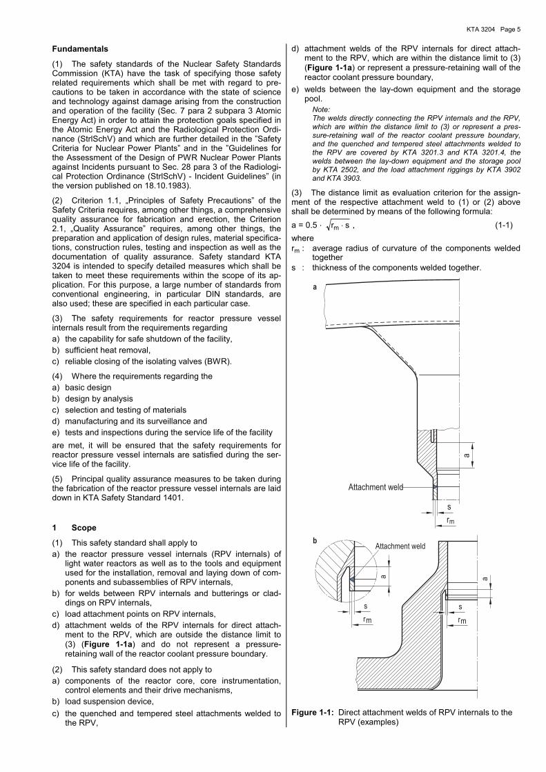
c) load attachment points on RPV internals, d) attachment welds of the RPV internals for direct attach-
ment to the RPV, which are outside the distance limit to (3) (Figure 1-1a) and do not represent a pressure-retaining wall of the reactor coolant pressure boundary.
(2) This safety standard does not apply to a) components of the reactor core, core instrumentation,
control elements and their drive mechanisms, b) load suspension device, c) the quenched and tempered steel attachments welded to
the RPV,
d) attachment welds of the RPV internals for direct attach-ment to the RPV, which are within the distance limit to (3) (Figure 1-1a) or represent a pressure-retaining wall of the reactor coolant pressure boundary,
e) welds between the lay-down equipment and the storage pool.
Note: The welds directly connecting the RPV internals and the RPV, which are within the distance limit to (3) or represent a pres-sure-retaining wall of the reactor coolant pressure boundary, and the quenched and tempered steel attachments welded to the RPV are covered by KTA 3201.3 and KTA 3201.4, the welds between the lay-down equipment and the storage pool by KTA 2502, and the load attachment riggings by KTA 3902 and KTA 3903.
(3) The distance limit as evaluation criterion for the assign-ment of the respective attachment weld to (1) or (2) above shall be determined by means of the following formula: a = 0.5 . srm ⋅ , (1-1) where rm : average radius of curvature of the components welded
together s : thickness of the components welded together.
m
Attachment weld
r
a
s
a
mm
Attachment weld
r
a
r
a
s s
b
Figure 1-1: Direct attachment welds of RPV internals to the RPV (examples)
KTA 3204 Page 6
2 Definitions
Note: The definitions regarding stress analysis are specified in Section 6.2.1.
(1) Plant vendor for nuclear facilities (A) A plant vendor for nuclear facilities is the person who received an order by a plant user or the future user of this facility for the planning and delivery of a nuclear facility or its compo-nents.
(2) Sub-unit A sub-unit is part of a component and consists of at least two parts.
(3) Part A part is the smallest item of a sub-unit manufactured from product forms.
(4) Threaded fasteners Threaded fasteners are fasteners which generally need not transfer residual gasket loads (e.g. screws, bolts, nuts).
(5) Specified operation Specified operation means operating conditions or changes in operating conditions consisting of normal or anomalous op-erational load cases.
(6) Plant user The plant user is the person responsible for the operation of a nuclear facility.
(7) Anomalous operational load cases Anomalous operational load cases are operating conditions arising from malfunctions of components or systems (dis-turbed condition) unless there are no objections as to the safe continuation of operation.
(8) Normal operational load cases Normal operational load cases are operating conditions for which the plant is designed and suited, with the systems be-ing functionally fit (undisturbed condition).
(9) Refuelling Refuelling is the entirety of tasks and work necessary for the shifting or replacement of spent or defective fuel elements to be removed from the core.
(10) Product form A product form is the form in its raw condition into which ma-terials are processed, e.g. plates and sheets, forgings and castings.
(11) Manufacturing Manufacturing comprises all tasks required for the construc-tion of a component.
(12) Verification of strength The verification of strength is intended to prove, by using the generally accepted engineering rules, that the component is able to withstand the loadings occurring during its service life.
(13) Functional capability Functional capability is the ability of a system or of one of its component parts (e.g., component, subsystem, train) includ-ing the necessary auxiliary, supply and power systems to perform the prescribed tasks.
(14) Manufacturer (H) The manufacturer is the person who, by specific order, will fabricate and test the equipment ordered, e.g. product form, component part, subassembly or component under his re-sponsibility.
(15) Verification of structural integrity The verification of structural integrity means a verification by analysis or experiments that the safety requirements (e.g. with respect to strength, resistance to failure, leak tightness)) for the component are satisfied.
(16) Component A component is that part of a system defined in terms of struc-tural or functional criteria, which still performs independent part functions.
(17) Load attachment point (LAP) The load attachment point is the connecting element between load suspension device and load and is either a) an integral part of the load or b) bolted on or c) welded on.
(18) Progressive surface examination Progressive surface examination is a liquid penetrant examina-tion performed progressively with a weld seam being built up.
Note: See also 8.9.1 (4).
(19) Supervision of tests and inspections This means the supervision during the performance of tests and inspections which is generally under the responsibility of the agency charged with such tests and inspections.
(20) Representative locations, components or component parts Such locations, components or component parts are consid-ered to be representative where the in-service inspection will lead to at least comparable safety related results for other locations, components or component parts, taking into con-sideration the material composition, design and manufactur-ing quality as well as the type, level and frequency of loading.
(21) Authorized inspector (S) For the purpose of this standard, this is the inspector charged by the licensing or supervising authority to perform inspec-tions in accordance with § 20 of the Atomic Energy Act.
(22) Incidents Incidents are deviations from specified operation in the event of which the operation of the plant cannot be continued for safety reasons:
A Emergencies (NF) Emergencies are incidents having very little probability of
occurrence
B Accidents (SF) Accidents are incidents having an extremely little prob-
ability of occurrence, or are postulated load cases.
(23) Subcontractor Subcontractor is the person who, by specific order of a manu-facturer, will fabricate and test the equipment ordered, e.g. product form, machine element, component part, subassembly or component under his or the manufacturer�s responsibility.
(24) Design approval The design approval is the safety-related assessment of the design and construction, the verification of strength of the materials used, the manufacturing processes, the test and inspection schedule, the circuitry, the possibility of performing in-service inspections, the accessibility for maintenance and repair, and the equipment used for operational monitoring, by means of the plans, written instructions, drawings and calcula-tions established for manufacture with reference to the re-quirements contained in the licence, in KTA safety standards and other technical rules.

KTA 3204 Page 7
3 Quality classes
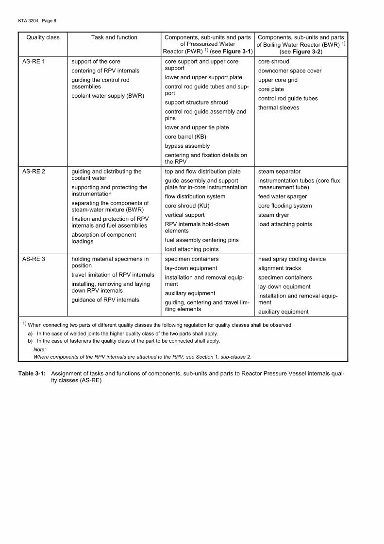
(1) All components, sub-units or parts of Reactor Pressure Vessel internals are assigned to quality classes with respect to their different tasks and functions (Table 3-1).
(2) Components, sub-units and parts of quality class �AS-RE 1� are structures which, according to their tasks and func-tions, shall ensure a safe possibility of shutdown and residual heat removal. The structural integrity and functional capability of these components, sub-units and parts shall be proven for normal operation and anticipated operational occurrences (levels A and B) and for incidents (levels C and D).
(3) Components, sub-units and parts of quality class �AS-RE 2� are structures which, according to their tasks and func-tions, do not directly ensure the safe possibility of shutdown and residual heat removal. The structural integrity and func-
tional capability of these components, sub-units and parts shall be proven for normal operation and anticipated opera-tional occurrences (levels A and B), however, failure of these components, sub-units and parts shall not impair the safe shutdown and residual heat removal.
(4) Components, sub-units and parts of quality class �AS-RE 3� are structures with subordinate tasks and func-tions and accessories. With regard to the requirements, they are classified as follows: a) the structural integrity and functional capability of compo-
nents, sub-units and parts of quality class �AS-RE 3 within the RPV� shall be proven like for components, sub-units and parts of quality class �AS-RE 2�.
b) for components, sub-units and parts of quality class �AS-RE 3 outside the RPV� the general standards and rules of engineering practice apply.
KTA 3204 Page 8
Quality class Task and function Components, sub-units and parts of Pressurized Water
Reactor (PWR) 1) (see Figure 3-1)
Components, sub-units and parts of Boiling Water Reactor (BWR) 1)
(see Figure 3-2)
AS-RE 1 support of the core centering of RPV internals guiding the control rod assemblies coolant water supply (BWR)
core support and upper core support lower and upper support plate control rod guide tubes and sup-port support structure shroud control rod guide assembly and pins lower and upper tie plate core barrel (KB) bypass assembly centering and fixation details on the RPV
core shroud downcomer space cover upper core grid core plate control rod guide tubes thermal sleeves
AS-RE 2 guiding and distributing the coolant water supporting and protecting the instrumentation separating the components of steam-water mixture (BWR) fixation and protection of RPV internals and fuel assemblies absorption of component loadings
top and flow distribution plate guide assembly and support plate for in-core instrumentation flow distribution system core shroud (KU) vertical support RPV internals hold-down elements fuel assembly centering pins load attaching points
steam separator instrumentation tubes (core flux measurement tube) feed water sparger core flooding system steam dryer load attaching points
AS-RE 3 holding material specimens in position travel limitation of RPV internals installing, removing and laying down RPV internals guidance of RPV internals
specimen containers lay-down equipment installation and removal equip-ment auxiliary equipment guiding, centering and travel lim-iting elements
head spray cooling device alignment tracks specimen containers lay-down equipment installation and removal equip-ment auxiliary equipment
1) When connecting two parts of different quality classes the following regulation for quality classes shall be observed: a) In the case of welded joints the higher quality class of the two parts shall apply. b) In the case of fasteners the quality class of the part to be connected shall apply.
Note: Where components of the RPV internals are attached to the RPV, see Section 1, sub-clause 2.
Table 3-1: Assignment of tasks and functions of components, sub-units and parts to Reactor Pressure Vessel internals qual-ity classes (AS-RE)
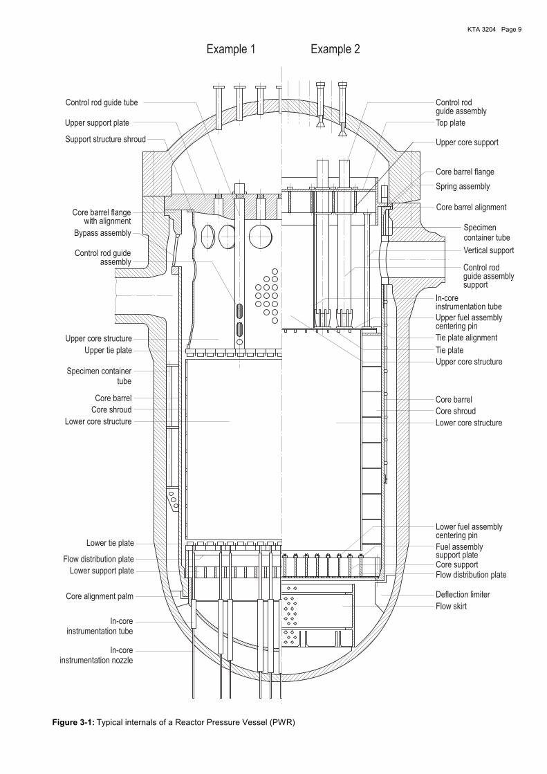
KTA 3204 Page 9
Example 2Example 1
Control rod guideassembly
Upper core structure
Specimen containertube
Upper tie plate
Bypass assembly
Support structure shroud
Upper support plate
Core barrel flangewith alignment
Core barrel
In-coreinstrumentation tube
In-coreinstrumentation nozzle
Lower fuel assemblycentering pin
Core alignment palm
Lower core structure
Core shroud
Lower tie plate
Lower support plate
Flow distribution plate
Control rodguide assemblysupport
Vertical support
instrumentation tube
Lower core structure
Tie plate alignment
Top plate
guide assemblyControl rod
Core barrel alignment
In-core
Upper core structure
Core support
Tie plate
Deflection limiter
Control rod guide tube
Core barrel flange
Upper fuel assemblycentering pin
Specimencontainer tube
Core shroud
Fuel assemblysupport plate
Core barrel
Spring assembly
Flow skirt
Flow distribution plate
Upper core support
Figure 3-1: Typical internals of a Reactor Pressure Vessel (PWR)
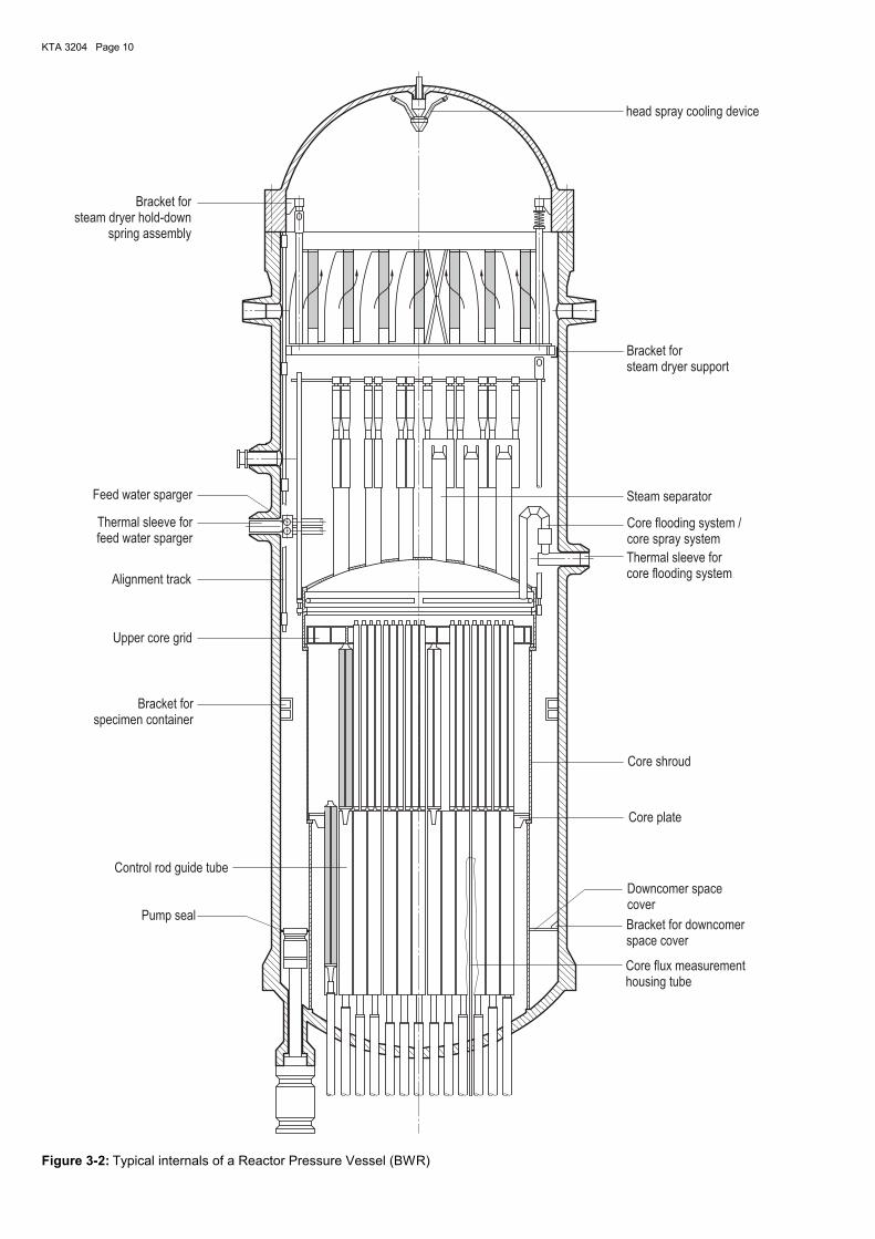
KTA 3204 Page 10
Thermal sleeve forcore flooding system
Core shroud
Downcomer spacecover
Bracket forsteam dryer support
Bracket forsteam dryer hold-down
spring assembly
Steam separator
Pump seal
Core plate
Bracket forspecimen container
Control rod guide tube
Core flux measurementhousing tube
Core flooding system /core spray system
Feed water sparger
Bracket for downcomerspace cover
Alignment track
Upper core grid
Thermal sleeve forfeed water sparger
head spray cooling device
Figure 3-2: Typical internals of a Reactor Pressure Vessel (BWR)
KTA 3204 Page 11
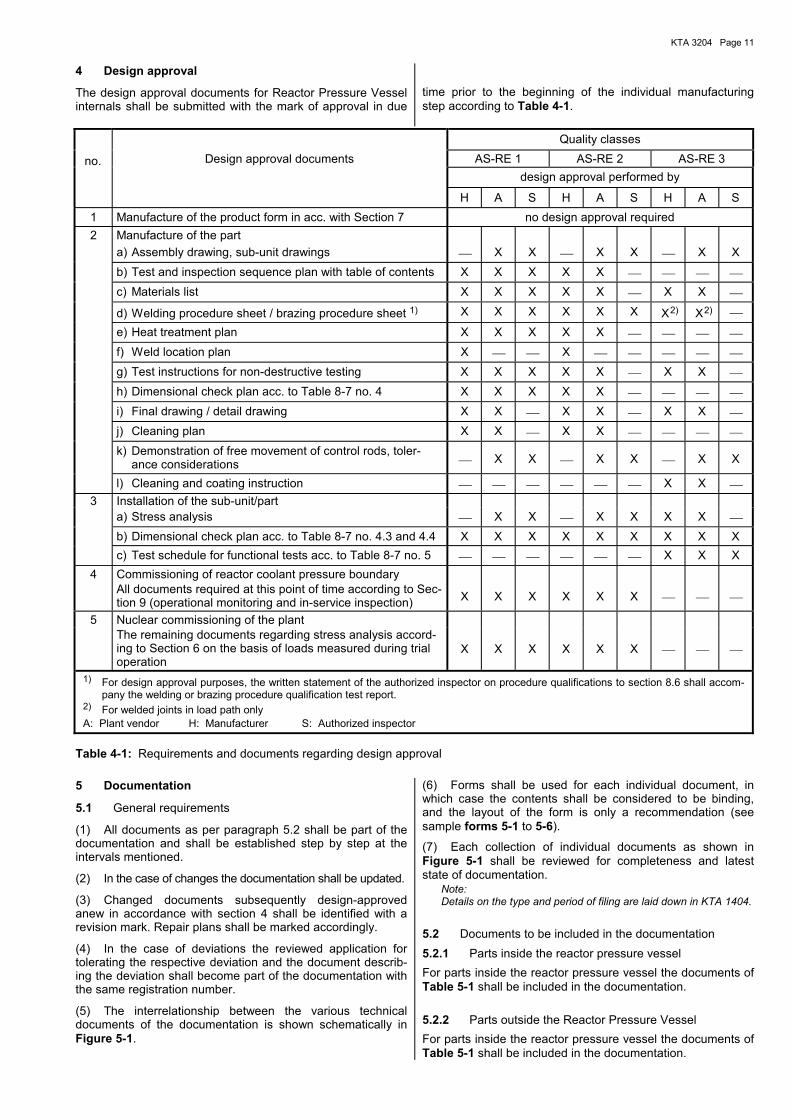
4 Design approval
The design approval documents for Reactor Pressure Vessel internals shall be submitted with the mark of approval in due
time prior to the beginning of the individual manufacturing step according to Table 4-1.
Quality classes Design approval documents AS-RE 1 AS-RE 2 AS-RE 3
design approval performed by
H A S H A S H A S 1 Manufacture of the product form in acc. with Section 7 no design approval required 2 Manufacture of the part a) Assembly drawing, sub-unit drawings X X X X X X b) Test and inspection sequence plan with table of contents X X X X X c) Materials list X X X X X X X d) Welding procedure sheet / brazing procedure sheet 1) X X X X X X X
2) X 2)
e) Heat treatment plan X X X X X f) Weld location plan X X g) Test instructions for non-destructive testing X X X X X X X h) Dimensional check plan acc. to Table 8-7 no. 4 X X X X X i) Final drawing / detail drawing X X X X X X j) Cleaning plan X X X X k) Demonstration of free movement of control rods, toler-
ance considerations X X X X X X
l) Cleaning and coating instruction X X 3 Installation of the sub-unit/part a) Stress analysis X X X X X X b) Dimensional check plan acc. to Table 8-7 no. 4.3 and 4.4 X X X X X X X X X c) Test schedule for functional tests acc. to Table 8-7 no. 5 X X X
4 Commissioning of reactor coolant pressure boundary All documents required at this point of time according to Sec-
tion 9 (operational monitoring and in-service inspection) X X X X X X
5 Nuclear commissioning of the plant The remaining documents regarding stress analysis accord-
ing to Section 6 on the basis of loads measured during trial operation
X X X X X X
1) For design approval purposes, the written statement of the authorized inspector on procedure qualifications to section 8.6 shall accom-pany the welding or brazing procedure qualification test report.
2) For welded joints in load path only A: Plant vendor H: Manufacturer S: Authorized inspector
Table 4-1: Requirements and documents regarding design approval 5 Documentation
5.1 General requirements
(1) All documents as per paragraph 5.2 shall be part of the documentation and shall be established step by step at the intervals mentioned.
(2) In the case of changes the documentation shall be updated.
(3) Changed documents subsequently design-approved anew in accordance with section 4 shall be identified with a revision mark. Repair plans shall be marked accordingly.
(4) In the case of deviations the reviewed application for tolerating the respective deviation and the document describ-ing the deviation shall become part of the documentation with the same registration number.
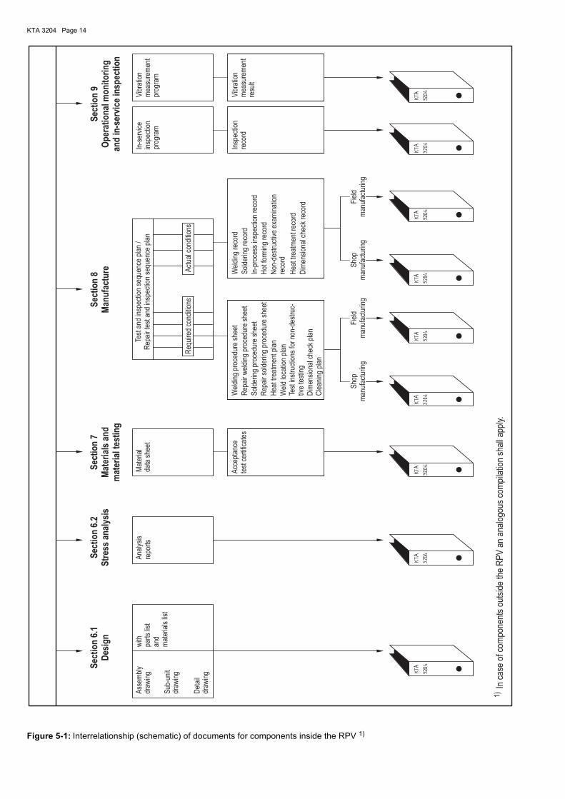
(5) The interrelationship between the various technical documents of the documentation is shown schematically in Figure 5-1.
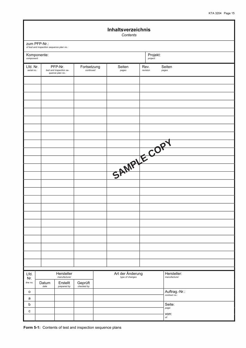
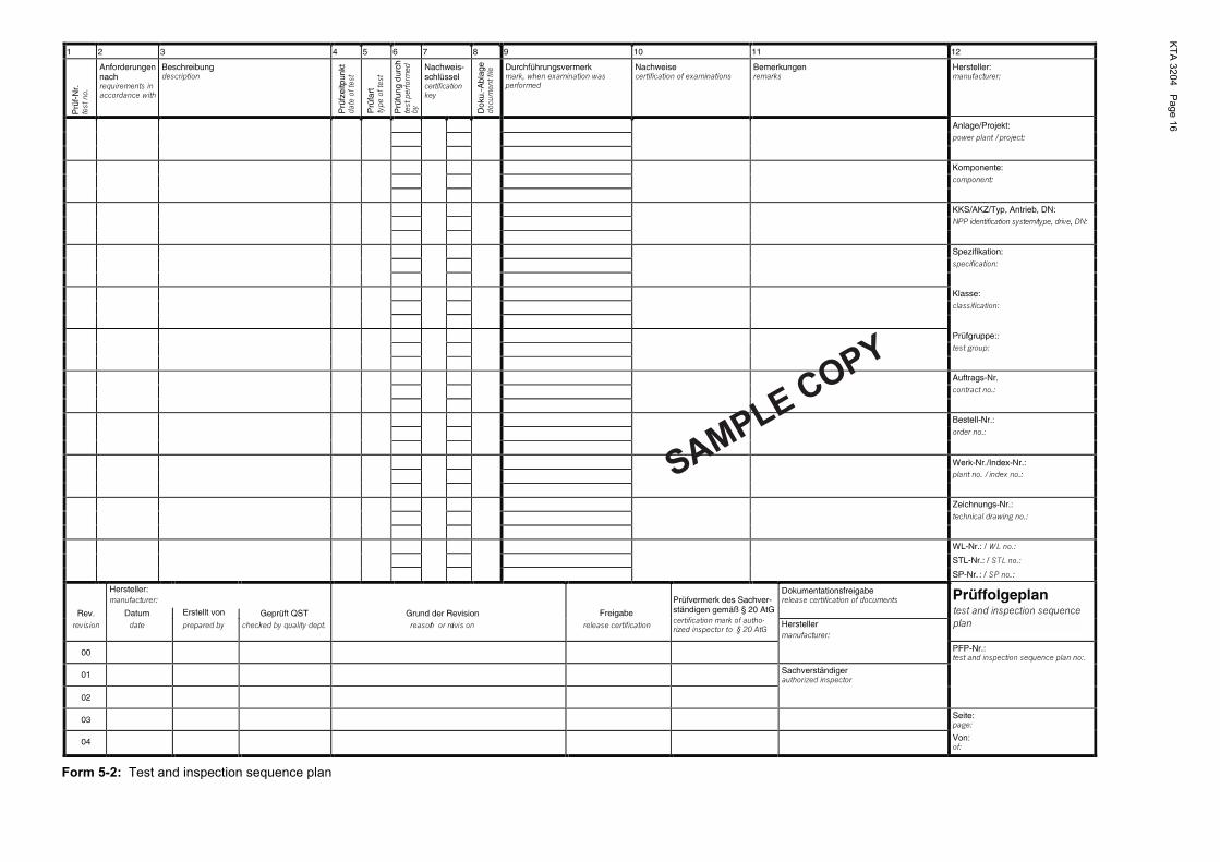
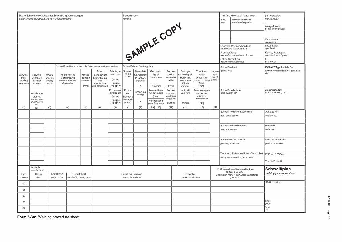
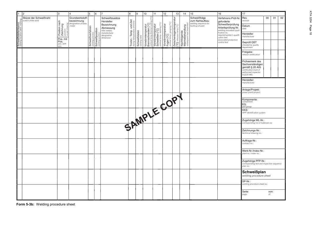
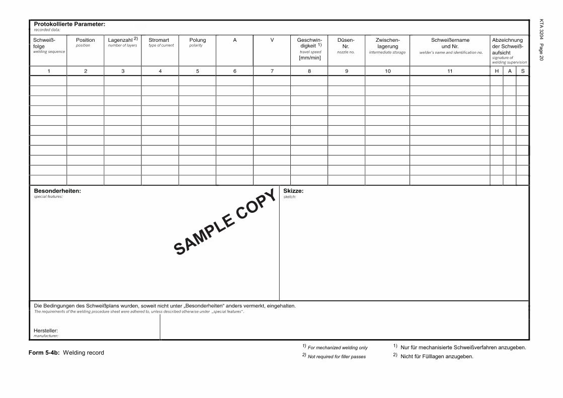
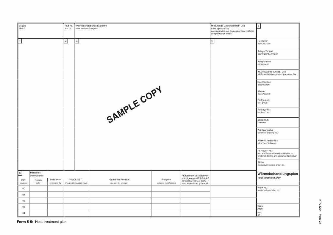
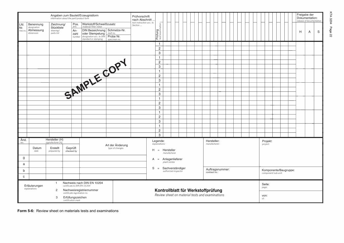
(6) Forms shall be used for each individual document, in which case the contents shall be considered to be binding, and the layout of the form is only a recommendation (see sample forms 5-1 to 5-6).
(7) Each collection of individual documents as shown in Figure 5-1 shall be reviewed for completeness and latest state of documentation.
Note: Details on the type and period of filing are laid down in KTA 1404.
5.2 Documents to be included in the documentation 5.2.1 Parts inside the reactor pressure vessel For parts inside the reactor pressure vessel the documents of Table 5-1 shall be included in the documentation. 5.2.2 Parts outside the Reactor Pressure Vessel For parts inside the reactor pressure vessel the documents of Table 5-1 shall be included in the documentation.
no.
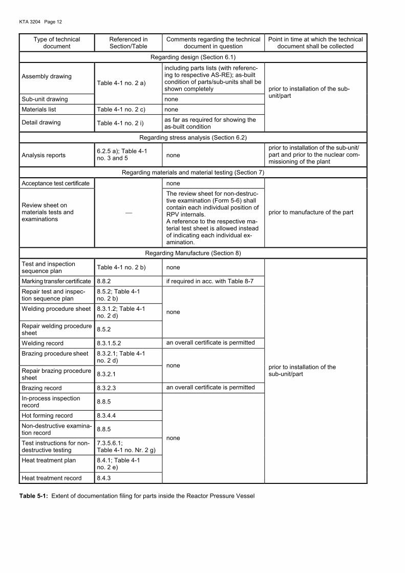
KTA 3204 Page 12
Type of technical document
Referenced in Section/Table
Comments regarding the technical document in question
Point in time at which the technical document shall be collected
Regarding design (Section 6.1)
Assembly drawing
including parts lists (with referenc-ing to respective AS-RE); as-built condition of parts/sub-units shall be shown completely
Sub-unit drawing
Table 4-1 no. 2 a)
none
Materials list Table 4-1 no. 2 c) none
Detail drawing Table 4-1 no. 2 i) as far as required for showing the as-built condition
prior to installation of the sub-unit/part
Regarding stress analysis (Section 6.2)
Analysis reports 6.2.5 a); Table 4-1 no. 3 and 5 none
prior to installation of the sub-unit/ part and prior to the nuclear com-missioning of the plant
Regarding materials and material testing (Section 7)
Acceptance test certificate none
Review sheet on materials tests and examinations
The review sheet for non-destruc-tive examination (Form 5-6) shall contain each individual position of RPV internals. A reference to the respective ma-terial test sheet is allowed instead of indicating each individual ex-amination.
prior to manufacture of the part
Regarding Manufacture (Section 8)
Test and inspection sequence plan Table 4-1 no. 2 b) none
Marking transfer certificate 8.8.2 if required in acc. with Table 8-7
Repair test and inspec-tion sequence plan
8.5.2; Table 4-1 no. 2 b)
Welding procedure sheet 8.3.1.2; Table 4-1 no. 2 d)
Repair welding procedure sheet 8.5.2
none
Welding record 8.3.1.5.2 an overall certificate is permitted
Brazing procedure sheet 8.3.2.1; Table 4-1 no. 2 d)
Repair brazing procedure sheet 8.3.2.1
none
Brazing record 8.3.2.3 an overall certificate is permitted
In-process inspection record 8.8.5
Hot forming record 8.3.4.4
Non-destructive examina-tion record 8.8.5
Test instructions for non-destructive testing
7.3.5.6.1; Table 4-1 no. Nr. 2 g)
Heat treatment plan 8.4.1; Table 4-1 no. 2 e)
Heat treatment record 8.4.3
none
prior to installation of the sub-unit/part
Table 5-1: Extent of documentation filing for parts inside the Reactor Pressure Vessel
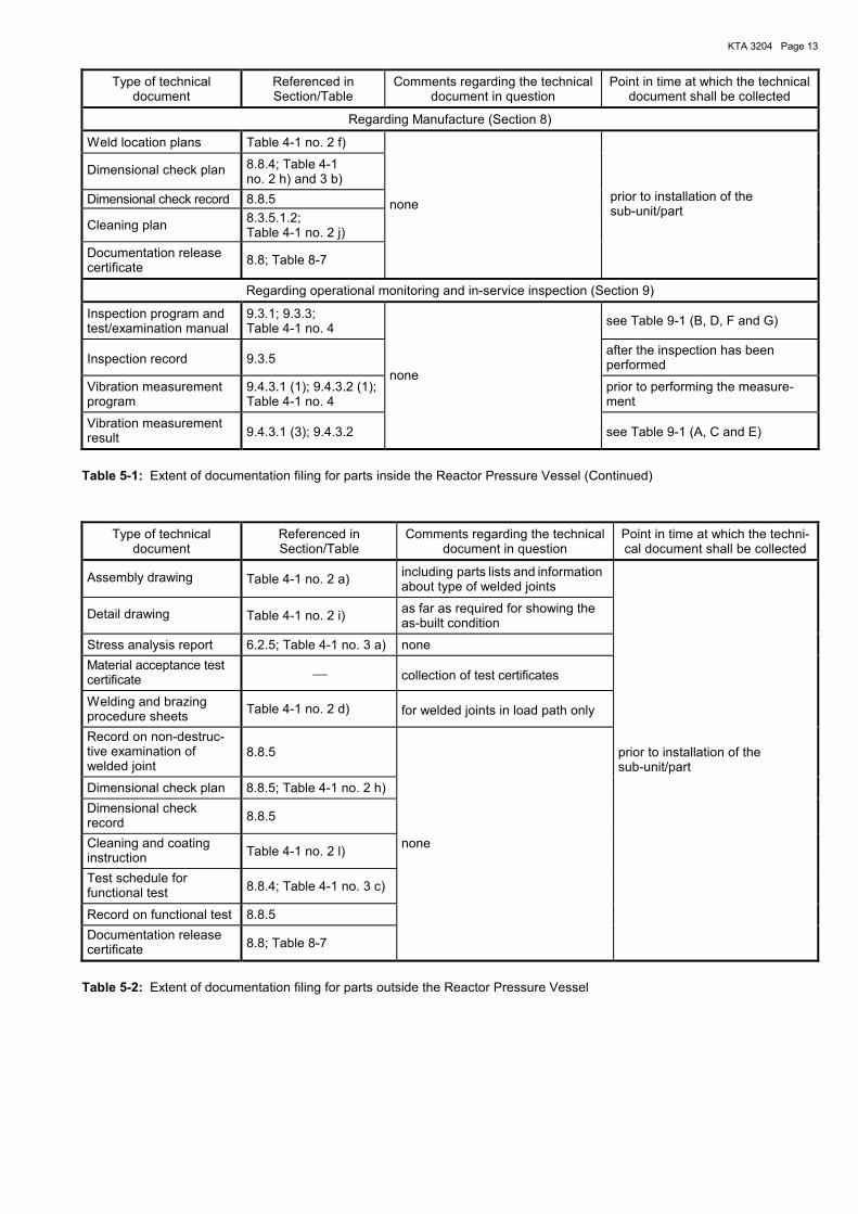
KTA 3204 Page 13
Type of technical document
Referenced in Section/Table
Comments regarding the technical document in question
Point in time at which the technical document shall be collected
Regarding Manufacture (Section 8)
Weld location plans Table 4-1 no. 2 f)
Dimensional check plan 8.8.4; Table 4-1 no. 2 h) and 3 b)
Dimensional check record 8.8.5
Cleaning plan 8.3.5.1.2; Table 4-1 no. 2 j)
Documentation release certificate 8.8; Table 8-7
none prior to installation of the sub-unit/part
Regarding operational monitoring and in-service inspection (Section 9)
Inspection program and test/examination manual
9.3.1; 9.3.3; Table 4-1 no. 4 see Table 9-1 (B, D, F and G)
Inspection record 9.3.5 after the inspection has been performed
Vibration measurement program
9.4.3.1 (1); 9.4.3.2 (1); Table 4-1 no. 4
prior to performing the measure-ment
Vibration measurement result 9.4.3.1 (3); 9.4.3.2
none
see Table 9-1 (A, C and E)
Table 5-1: Extent of documentation filing for parts inside the Reactor Pressure Vessel (Continued)
Type of technical document
Referenced in Section/Table
Comments regarding the technical document in question
Point in time at which the techni-cal document shall be collected
Assembly drawing Table 4-1 no. 2 a) including parts lists and information about type of welded joints
Detail drawing Table 4-1 no. 2 i) as far as required for showing the as-built condition
Stress analysis report 6.2.5; Table 4-1 no. 3 a) none Material acceptance test certificate collection of test certificates
Welding and brazing procedure sheets Table 4-1 no. 2 d) for welded joints in load path only
Record on non-destruc-tive examination of welded joint
8.8.5
Dimensional check plan 8.8.5; Table 4-1 no. 2 h) Dimensional check record 8.8.5
Cleaning and coating instruction Table 4-1 no. 2 l)
Test schedule for functional test 8.8.4; Table 4-1 no. 3 c)
Record on functional test 8.8.5 Documentation release certificate 8.8; Table 8-7
none
prior to installation of the sub-unit/part
Table 5-2: Extent of documentation filing for parts outside the Reactor Pressure Vessel
KTA 3204 Page 14
Sec
tio
n7
Mat
eria
lsan
dm
ater
ialt
esti
ng
Sec
tio
n6.
2S
tres
san
alys
isS
ecti
on
8M
anu
fact
ure
Sec
tio
n9
Op
erat
ion
alm
on
ito
rin
gan
din
-ser
vice
insp
ecti
on
Sec
tio
n6.
1D
esig
n
Act
ualc
ondi
tions
Req
uire
dco
nditi
ons
Sho
pm
anuf
actu
ring
Test
and
insp
ectio
nse
quen
cepl
an/
Rep
air
test
and
insp
ectio
nse
quen
cepl
anV
ibra
tion
Rep
air
sold
erin
gpr
oced
ure
shee
t
Sol
derin
gpr
oced
ure
shee
t
Hea
ttre
atm
entp
lan
Dim
ensi
onal
chec
kpl
an
Wel
dlo
catio
npl
anTe
stin
stru
ctio
nsfo
rno
n-de
stru
c-tiv
ete
stin
g
reco
rdIn
spec
tion
Rep
air
wel
ding
proc
edur
esh
eet
Wel
ding
proc
edur
esh
eet
In-p
roce
ssin
spec
tion
reco
rd
Hot
form
ing
reco
rd
Sol
derin
gre
cord
1)
Wel
ding
reco
rd
Dim
ensi
onal
chec
kre
cord
Cle
anin
gpl
an
Hea
ttre
atm
entr
ecor
d
Non
-des
truc
tive
exam
inat
ion
reco
rd
Vib
ratio
n
data
shee
tM
ater
ial
Ana
lysi
sre
port
spa
rts
list
and
mat
eria
lslis
t
with
prog
ram
mea
sure
men
tpr
ogra
m
In-s
ervi
cein
spec
tion
Acc
epta
nce
test
cert
ifica
tes
Ass
embl
y
mea
sure
men
tre
sult
Det
ail
draw
ing
Sub
-uni
t
draw
ing
draw
ing
Inca
seof
com
pone
nts
outs
ide
the
RP
Van
anal
ogou
sco
mpi
latio
nsh
alla
pply
.
Fie
ldm
anuf
actu
ring
Sho
pm
anuf
actu
ring
Fie
ldm
anuf
actu
ring
Figure 5-1: Interrelationship (schematic) of documents for components inside the RPV 1)
KTA 3204 Page 15
SAMPLE COPY
Inhaltsverzeichnis Contents
zum PFP-Nr.: of test and inspection sequence plan no.:
Komponente: component:
Projekt: project:
Lfd. Nr. serial no.:
PFP-Nr. test and inspection se-
quence plan no.: Fortsetzung
continued Seiten
pages Rev. Seiten revision pages
Hersteller manufacturer
Art der Änderung type of changes
Hersteller: manufacturer:
Lfd. Nr.
line no.
Datum date
Erstellt prepared by
Geprüft checked by
o
a
Auftrag.-Nr.: contract no.:
b
c
Seite: page:
von: of:
Form 5-1: Contents of test and inspection sequence plans
KTA
3204 Page 16
SAMPLECOPY
Form 5-2: Test and inspection sequence plan
KTA
3204 Page 17
working
Arbeits-
DIN ENISO 14175
DIN ENISO 14175
Form 5-3a: Welding procedure sheet
KTA
3204 Page 18
SAMPLECOPY
Form 5-3b: Welding procedure sheet

KTA 3204 Page 19
Dauer der Schweißung von .................... bis .......................... duration of welding from until Schweißplan-Nr.: ...................................................................... welding procedure sheet no.: Bezeichnung der Schweißstelle: .............................................. weld designation: Grundwerkstoff: ........................................................................ base metal: Arbeitsprüf-Nr.: ......................................................................... production control test no.: Gültige Verfahrensprüfg.-Nr.: ................................................... valid welding procedure qualification no.:
Verwendete Schweißgeräte: welding equipment used:
Verfahren process
Masch.-Typ equipment type
Masch.-Nr. equipment no.
Besondere Vorrichtungen special equipment
Verwendete Schweißzusätze: filler metals used:
Schweißfolge welding sequence
Verfahren process
Bezeichnung designation
Abmessung dimensions
Los-Nr. lot no.
Chargen-Nr. weld material test no.
Ausarbeiten der Wurzel durch: root gouged by:
PFP-Nr.: ............................................ test and inspection sequence plan no.:
Legende: Auftrags-Nr.: ..................................... contract no.:
Fertigungs- schritt-Nr.: .......................................... manufacturing step no.:
explanations: Projekt: project: Komponente: component:
Registrier-Nr.: .................................... registration no.:
Hersteller: manufacturer: Schweißprotokoll
welding record (SPK) SPK Seite:
page: von: of:
Form 5-4a: Welding record
SAMPLE COPY
KTA
3204 Page 20
SAMPLECOPY
Form 5-4b: Welding record 1) For mechanized welding only 1) Nur für mechanisierte Schweißverfahren anzugeben. 2) Not required for filler passes 2) Nicht für Fülllagen anzugeben.
KTA
3204 Page 21
Form 5-5: Heat treatment plan
KTA
3204 Page 22
Geprüftchecked by
Auftragsnummer:contract no.:
SAMPLECOPY
Form 5-6: Review sheet on materials tests and examinations
KTA 3204 Page 23
6 Design and stress analysis
6.1 Design
6.1.1 General requirements
The design of the reactor pressure vessel internals shall a) meet the functional requirements b) not lead to an increase of loadings/stresses c) meet the specific requirements of the materials d) meet fabrication and inspection and testing requirements e) be amenable to maintenance f) meet the operational requirements.
with respect to the interaction between aforementioned general requirements.
6.1.2 Tolerances
For all dimensions for which no tolerances are shown in the drawings, DIN ISO 2768-1 and DIN ISO 2768-2 (accuracy level: medium) as well as DIN EN ISO 13920 (accuracy level: C) shall apply.
6.1.3 Deviations from specified shape and location
(1) Deviations from specified shape and location shall be indicated in accordance with DIN EN ISO 1101.
(2) The maximum deviations from shape and location shall be specified by the plant vendor.
6.1.4 Surfaces
(1) The surface qualities shall be specified in accordance with sequence 2 of DIN EN ISO 1302.
(2) The root mean square Ra shall be limited to 10 µm. Note: The root mean square values to be adhered to shall be specified by the plant vendor.
6.1.5 Fasteners
(1) Only safeguarded fasteners which are not susceptible to cracking (e.g. threaded fasteners, nuts and pins) shall be used.
(2) Austenitic threaded fasteners for structural fasteners that are to be detached regularly shall have rolled threads or threads with additional backlash at thread crest or flank as well as show rounded edges.
6.1.6 Welded joints
(1) For parts inside the reactor pressure vessel the weld factors and fatigue strength reduction factors can be obtained from Table 6-1 in dependence of the non-destructive exami-nations performed and the requirements for the welded joint.
(2) The welded joints are assigned to categories A to F (see Table 8-3). The type of welded joints shall be determined in consideration of Tables 8-3 and 6-1.
(3) For parts outside the reactor pressure vessel the DIN Standards or rules of conventional engineering shall apply.
(4) In the following, the range of application of the welded joints is described. Examples for their application are given in Figures 6-1 and 6-2. a) Welded joint categories A1, A2 and B1 These weld groups are used e.g. for butt, longitudinal or
circumferential welds and as T-joints, corner joints or nozzle welds. The examination of the cover pass shall be
made from both sides. For the evaluation with respect to the weld factor and fatigue strength reduction factor, line 1 from Table 6-1 applies.
b) Welded joint categories A3 and B2 For the application the requirements of a) apply. For the
evaluation with respect to the weld factor and fatigue strength reduction factor, line 2 of Table 6-1 applies. Where these weld joint categories do not meet the re-quirements of 8.3.1.4 on the root side, line 1 of Table 6-1 applies.
c) Welded joint category C This category is used for butt welds if the conditions amin ≥ 1/8 s2 and s2 ≤ s1 are satisfied (s1 = greater wall thickness; s2 = smaller wall
thickness; amin = minimum throat thickness). The cover pass shall be examined from both sides. For the evaluation of the weld factor and fatigue strength
reduction factor, line 3 of Table 6-1 applies. d) Welded joint category D This category is e.g. used for T-joints, corner joints and
nozzle welds. The cover pass shall be examined from both sides. For
the evaluation of the weld factor and fatigue strength re-duction factor, line 4 of Table 6-1 applies.
e) Welded joint categories E and F This categories are e.g. used for T-joints, angle joints,
corner joints or nozzle welds. For the evaluation of the weld factor and fatigue strength
reduction factor, lines 5 to 7 of Table 6-1 apply. 6.2 Stress analysis 6.2.1 Definitions (1) Equivalent linear (bending) stress Equivalent linear bending stress is defined as the linear stress distribution which has the same net bending moment as the actual stress distribution. (2) Equivalent static pressure difference Equivalent static pressure difference is the pressure differ-ence on a shell or plate which, when applied statically, causes the same loading as a dynamically acting pressure difference loading. (3) Gross structural discontinuity Gross structural discontinuity is a geometric or material dis-continuity which effects the stress or strain distribution through the entire wall thickness of the shell-type member. Gross-discontinuity type stresses are those portions of the actual stress distribution that produce net bending and mem-brane force resultants when integrated through the wall thick-ness.
Note: Examples of gross structural discontinuities are head-to-shell and flange-to-shell junctions, nozzles, and junctions between shells of different thicknesses or materials.
(4) Expansion stresses Expansion stresses are those stresses resulting from restraint of free end displacement of piping which may act as core support structure.
(5) Expansion stress intensity This is the equivalent stress intensity of an expansion stress.
(6) Best-fit-curve The best-fit curve is that logarithmic curve which adapts to the material fatigue tests according to the method of least squares of deviations.
KTA 3204 Page 24
(7) Stress/strain loadings These are stresses or strains arising from loadings on the component or part.
Note: In the case of a linear elastic relationship stresses and strains are proportional to each other. In the case of an elastic stress analy-sis according to 6.2.4.2.2 and a fatigue analysis according to 6.2.4.2.3 this proportional ratio even when in excess of the yield strength or proof stress of the material shall be the basis of analy-sis (fictitious stresses). Where elastic-plastic analyses are made, the effective stress-strain relationship with respect to the actual material behaviour shall be taken into account (effective stresses).
The loadings are static or dynamic loadings.
(8) Service limit Service limit is a maximum allowable stress or strain value.
(9) Design loading level Design loading level is a specific category of service limits to safeguard against various types of failure.
Note: Examples are: Limitation of plastic deformation, avoidance of fail-ure due to progressive deformation (ratcheting) and fatigue.
(10) Operational cycle Operational cycle is defined as the initiation and establish-ment of new conditions followed by a return to the conditions which prevailed at the beginning of the cycle.
(11) Bending stress Bending stress is the variable component of normal stress. The variation may or may not be linear across the thickness.
Note: See also definition of �normal stress�.
(12) Strain cycling test Strain cycling test is a strain-controlled test to cover the cyclic loading of a material to rupture or to a previously fixed number of cycles.
Note: See also 6.2.4.3.5.
(13) Deformation Deformation is the alteration of the shape or geometry of the component, the part or the idealized structure due to loadings. Deformations can be described by displacements and twist-ing. If required, they shall be limited such that the functional capability of the component and its adjacent components is not impaired.
(14) Shakedown Shakedown is the absence of a continuing cycle of plastic deformation if creep effects are excluded. A structure shakes down if after a few cycles of load application the deformation stabilizes and subsequent structural response is elastic.
(15) Elastic-plastic material behaviour Elastic-plastic material behaviour is defined as the deforma-tion behaviour of a material whose response under load is primarily elastic and, upon exceeding a specific stress value, is elastic-plastic. The total strain εges corresponding to elastic-plastic deformation is composed of an elastic portion εe and a plastic portion εp.
(16) Fatigue Fatigue is the cumulative usage of the material caused by cyclic loading, which may lead to failure due to cracking.
(17) Fatigue strength reduction factor Fatigue strength reduction factor is a stress intensification factor which accounts for the effect of a local structural dis-continuity (stress concentration) on the fatigue strength. The
fatigue strength reduction factor may be determined experi-mentally.
Note: See also 6.2.4.2.3 and D 3.
(18) Free end displacement Free end displacement consists of the relative motions that would occur between an attachment and connected structure or equipment if the two members were separated.
Note: Examples of such motions are those that would occur because of relative thermal expansion of piping equipment and equipment supports or because of rotations imposed upon the equipment by sources other than piping.
(19) Total stress Total stress is the sum of primary, secondary, and peak stress contributions. Recognition of each of the individual contribu-tions is essential to the establishment of appropriate limita-tions.
(20) Limit analysis - collapse load a) Collapse load The methods of limit analysis are used to compute the
maximum load or combinations of loads a structure made of ideally plastic (non strain-hardening) material can carry. The deformations of an ideally plastic structure increase without bound at this load termed collapse load. Among the methods used in limit analysis is a technique which assumes elastic, perfectly plastic, material behaviour and a constant level of moments or force in those redundant structural elements in which membrane yield, plastic hinge, or critical buckling load has been reached. Any in-crease in load must be accompanied by a stable primary structure until a failure mechanism defined by the lower bound theorem of limit analysis is reached in the primary structure.
b) Collapse load � Lower Bound The lower bound collapse load is a load equal to or
smaller than the collapse load for which any system of stresses can be found which everywhere satisfies equilib-rium and nowhere exceeds the fictitious material yield strength. This is the lower bound theorem of limit analysis which permits calculations of a lower bound to the col-lapse load.
(21) Principal strain range The numerically greatest strain cycling range of one of the three main directions of strain in a stress cycle.
(22) Inelasticity Inelasticity is a general characteristic of a material behaviour in which the material does not return to its original shape and size after removal of all applied loads. Plasticity and creep are special cases of elasticity.
(23) Inelastic analysis Inelastic analysis is a calculation method which accounts for the inelastic material behaviour in the structural response under given loadings (e.g. in the case of plastic analysis and limit analysis).
(24) Interaction equation Interaction equation is an equation which comprises and evaluates the various types of loadings such as bending and tension, or bending, tension and shear, at the ratio of the effective to the allowable loading. The sum must always be less than 1.0.
Note: See also Section C 2.
(25) Creep Creep is the special case of inelasticity that relates to the stress-induced time-dependent deformation under load. Small
KTA 3204 Page 25
time-dependent deformations may occur after the removal of all applied loads.
(26) Load case Load case is a state or change of state in the structure which leads to a loading on the component.
(27) Load case class Load case class is the assignment of load cases, e.g. normal operational load cases, to a specific class.
(28) Number of load cycles This is the number of load cycles.
(29) Mechanical loadings Mechanical loadings are forces, pressure differences and related deformations as far as they cause loadings.
(30) Load stress (= Stress due to mechanical load) Load stress is the stress resulting from the application of a mechanical load.
Note: Examples are stresses resulting from a pressure difference or the effects of gravity.
(31) Membrane stress Membrane stress is the component of the normal stress which is uniformly distributed and equal to the average of stress across the thickness of the section under consideration.
(32) Normal stress Normal stress is the component of stress normal to the plane of reference. Usually the distribution of normal stress is not uniform through the thickness of a part, so thus stress is con-sidered to be made up in turn of two components, one of which is uniformly distributed and equal to the average value of stress across the thickness under consideration, and the other of which varies from this average value with the location across the thickness.
(33) Local structural discontinuity Local structural discontinuity is a geometric or material dis-continuity which affects the stress or strain distribution through a fractional part of the wall thickness. The stress distribution associated with a local discontinuity causes only very localized types of deformation or strain and has no sig-nificant effect on the shell-type discontinuity deformation.
Note: Examples are small filled radii, small attachments and partial penetration single-vee and double-level groove welds as well as related types of weld.
(34) Plasticity Plasticity is the special case of inelasticity in which the mate-rial undergoes time-independent non-recoverable deforma-tion.
(35) Plastic analysis Plastic analysis is that method which computes the structural behaviour under given loads considering the plasticity charac-teristics of the material including strain hardening and the stress redistribution in the structure.
(36) Plastic instability load The plastic instability load for members under predominantly tensile or compressive loading is defined as that load at which unbounded plastic deformation can occur without an increase in load.
(37) Primary stress Primary stress is a normal or shear stress developed by im-posed loading which is necessary to satisfy the laws of equi-librium of forces and moments. Regarding the mechanical behaviour of a structure, the basic characteristic of this stress is that upon initiation of yielding of the cross-section the de-
formations will increase disproportionally with an increment of the external loads. Upon further inadmissibly high increment of the external loads deformations occur that are not self-limiting. A general primary membrane stress is one which is so distributed in the structure that no redistribution of load occurs as a result of yielding.
Note: Examples are: general membrane stress (Pm) in a circular cylin-drical or spherical shell due to internal pressure difference or dis-tributed live loads; bending stress (Pb) in the central portion of a flat head due to pressure difference.
(38) Ratcheting (progressive deformation) Ratcheting is a progressive incremental inelastic deformation or strain which can occur in a component that is subjected to variations of mechanical stress, thermal stress, or both.
(39) Ring/shell cross section The ring/shell cross-section is the equivalent cross-section composed of the combination of structural stiffeners and ef-fective shell-type member which has the same stiffness as the original shell and the reinforcement.
(40) Shear stress Shear stress is the component of stress tangent to the plane of reference.
(41) Secondary stress Secondary stress (Q) is a stress developed under mechanical or thermal loading due to a) geometric discontinuities, b) differing elastic constants (e.g. moduli of elasticity) and c) constraints due to differential thermal expansions. The basic characteristic of a secondary stress is that it is self-limiting. Local yielding and minor distortions can satisfy the conditions which cause the stress to occur, and failure from one application of the stress is not to be expected. For the linear-elastic analysis only stresses that are distributed line-arly across the cross-section are considered to be secondary stresses.
Note: Examples of secondary stresses are: general thermal stress; bending stress at a gross structural discontinuity.
(42) Stress analysis Stress analysis is the determination, by way of calculation, of types of stresses due to given loadings and the comparison of this stress types with the limited stress intensities of the indi-vidual stress categories.
(43) Limitation of stresses Limited stresses are allowable limits for the given loadings of the structure.
Note: Basic stress limits are Pm, Pm + Pb and Pm + Pb + Q in accordance with Tables 6-5 and 6-6.
(44) Stress concentration factor Stress concentration factor is that factor with which the nomi-nal stress portions have to be multiplied to obtain the total stress. It may be determined analytically or experimentally.
(45) Peak stress (Tertiary stress) Peak stress (F) is that increment of stress which is additive to the respective primary and secondary stresses. Peak stresses do not cause any noticeable distortion and are only important to fatigue and brittle fracture in conjunction with primary and secondary stresses. Peak stresses also comprise deviations from nominal stresses at hole edges within tube fields due to pressure and temperature in which case the nominal stresses shall be de-rived from the equilibrium of forces considerations.
KTA 3204 Page 26
Note: Examples are: stress due to local structural discontinuity; surface stresses caused by thermal stock; thermal stress in a structure, caused by a cladding; stress caused by the difference of the ac-tual temperature distribution from the equivalent linear tempera-ture distribution.
(46) Stress ratio method The methods of plastic analysis which utilize the stress ratio combinations are used to compute the maximum load a strain-hardened material can carry.
Note: (1) See also 6.2.4.2.7. (2) Stress ratio combinations are useful since the actual shape factor as a function of the cross section and the type and magni-tude of different stress fields may be considered in determining the load.
(47) Stress cycle (= Load cycle) Stress cycle is a condition in which the alternating stress difference goes from an initial value through an algebraic maximum value and an algebraic minimum value and then returns to the initial value. Dynamic conditions shall also be considered stress cycles.
Note: (1) See also 6.2.4.2.2.2.2. (2) A single service cycle may result in one or more stress cycles.
(48) Elastic ratio Elastic ratio is the 0.2% proof stress (Rp0.2), divided by the tensile strength (Rm).
(49) Thermal stress Thermal stress is a self-balancing stress produced by a non-uniform distribution of temperature or by differing coefficients of thermal expansion. Thermal stress is developed in a solid body whenever a volume of material is prevented from as-suming the size and shape that it normally should under a change in temperature. It is classified as secondary or tertiary stress. For the purpose of establishing allowable stresses, two types of thermal stress are recognized depending on the volume or area in which distortion takes place: a) A general thermal stress is associated with distortion of
the structure in which it occurs. If a stress of this type, ne-glecting stress concentrations, exceeds a certain limit value, the elastic analysis may be invalid and successive thermal cycles may produce incremental distortion. There-fore, this type of stress is classified as secondary stress in Table 6-4.
Note: Examples are: stress produced by an axial temperature distri-bution in a cylindrical shell; stress produced by the temperature difference between a nozzle and the shell to which it is at-tached; the equivalent linear stress [see definition (1)] produced by the radial temperature distribution in a cylindrical shell.
b) A local thermal stress is associated with almost com-plete suppression of the differential expansion and thus produces no significant distortion. Such stresses shall only be considered from the fatigue standpoint and are there-fore classified as local thermal stresses in Table 6-4. In evaluating local thermal stresses the procedure of 6.2.4.2.2.7, para 5 (b) shall be used.
Note: Examples are: the stress in a small hot spot in a vessel wall; the difference between the actual stress and the equivalent lin-ear stress resulting from a radial temperature distribution in a cylindrical shell; the thermal stress in a cladding material which has a coefficient of expansion different from that of the base metal.
(50) Thermal loadings Thermal loadings are loads from temperature fields, different thermal expansion and thermally induced displacements as far as they result in loadings.
(51) Trapezoidal stress Trapezoidal stress is defined as a fictitious stress occurring in the neutral fibre or during zero strain which results from trans-forming the non-linear stress/stain curve into a trapezoidal stress-strain curve.
Note: See also Section C 4.1.
(52) Equivalent stress intensity Equivalent stress intensity denotes a fictitious uniaxial stress which represents the same material loading as an effective multi-axial stress condition.
(53) Distortion Distortion is defined as the longitudinal or angular change in shape of a body, characterized by a change in distance be-tween two neighbouring points and the change of angle be-tween any two linear elements.
(54) Cyclic loading Cyclic loading is defined as the loading correlated to a stress cycle.
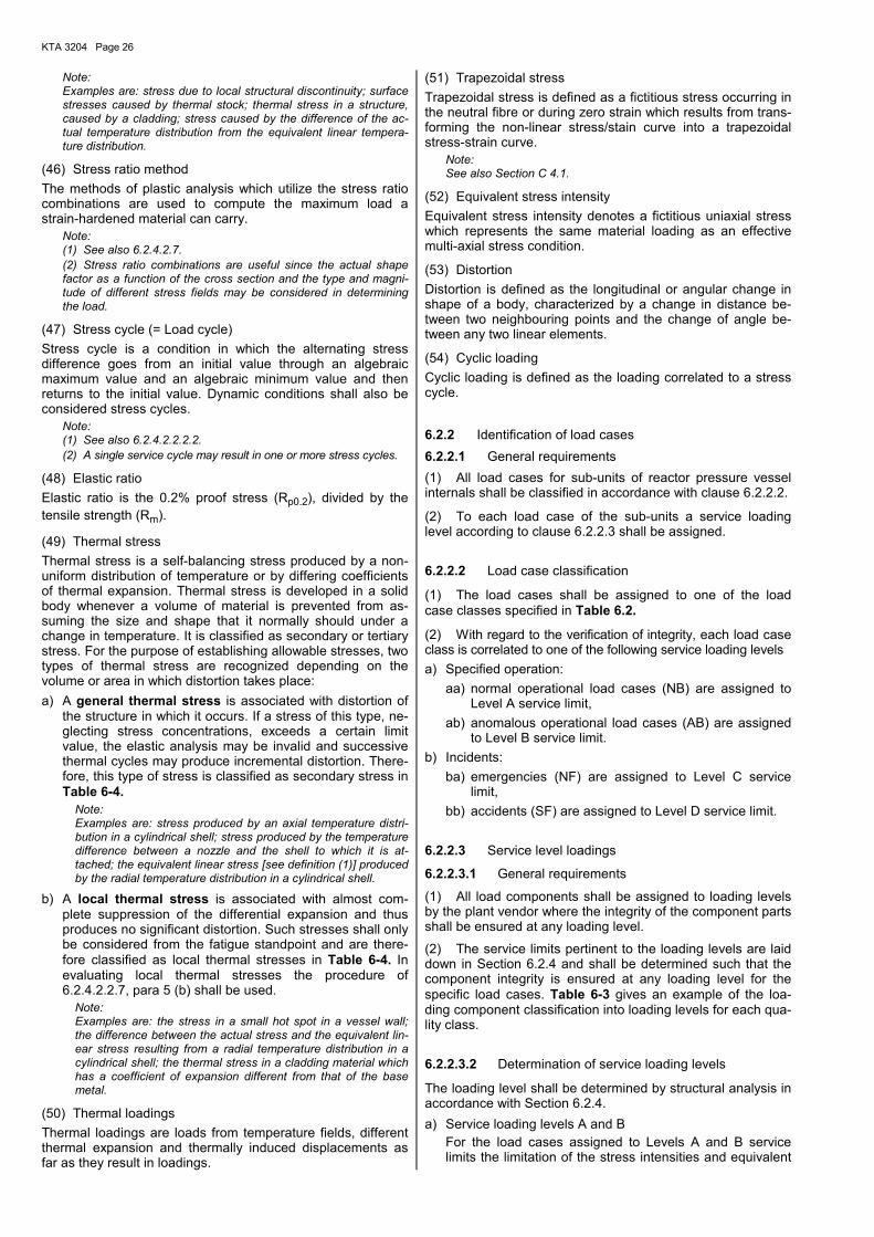
6.2.2 Identification of load cases 6.2.2.1 General requirements (1) All load cases for sub-units of reactor pressure vessel internals shall be classified in accordance with clause 6.2.2.2.
(2) To each load case of the sub-units a service loading level according to clause 6.2.2.3 shall be assigned.
6.2.2.2 Load case classification
(1) The load cases shall be assigned to one of the load case classes specified in Table 6.2.
(2) With regard to the verification of integrity, each load case class is correlated to one of the following service loading levels a) Specified operation:
aa) normal operational load cases (NB) are assigned to Level A service limit,
ab) anomalous operational load cases (AB) are assigned to Level B service limit.
b) Incidents: ba) emergencies (NF) are assigned to Level C service
limit, bb) accidents (SF) are assigned to Level D service limit.
6.2.2.3 Service level loadings
6.2.2.3.1 General requirements
(1) All load components shall be assigned to loading levels by the plant vendor where the integrity of the component parts shall be ensured at any loading level.
(2) The service limits pertinent to the loading levels are laid down in Section 6.2.4 and shall be determined such that the component integrity is ensured at any loading level for the specific load cases. Table 6-3 gives an example of the loa-ding component classification into loading levels for each qua-lity class.
6.2.2.3.2 Determination of service loading levels
The loading level shall be determined by structural analysis in accordance with Section 6.2.4. a) Service loading levels A and B For the load cases assigned to Levels A and B service
limits the limitation of the stress intensities and equivalent
KTA 3204 Page 27
stress intensity range with respect to progressive distortion and fatigue shall be verified in accordance with clauses 6.2.4.2.2.3 and 6.2.4.2.2.9, respectively.
b) Service loading level C For level C service limits only such loadings shall be con-
sidered which cause primary stresses. In addition, for the load cases assigned to level C the limitation of the stress intensity ranges with respect to progressive distortion and fatigue shall be verified in accordance with clauses 6.2.4.2.2.3 and 6.2.4.2.2.9, respectively. The service limits of level C allow for plastic deformations.
c) Service loading level D For level D service limits only loadings shall be considered
which cause primary stresses. Here, gross plastic defor-mation may occur.
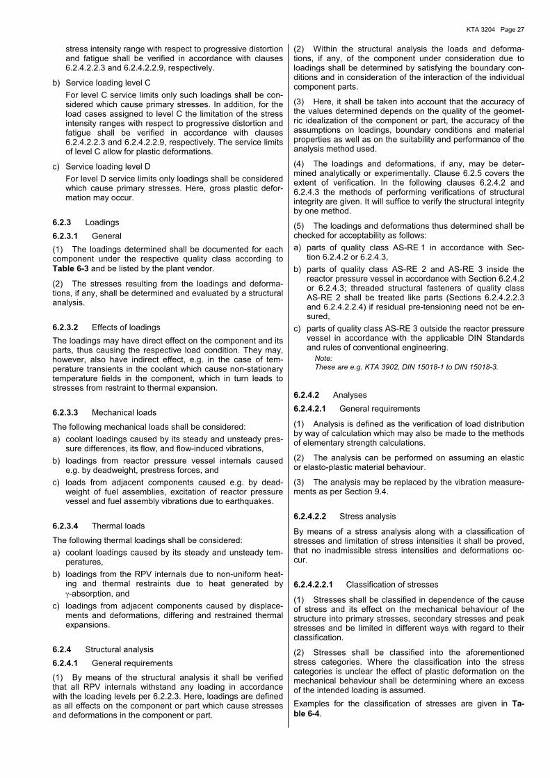
6.2.3 Loadings 6.2.3.1 General (1) The loadings determined shall be documented for each component under the respective quality class according to Table 6-3 and be listed by the plant vendor.
(2) The stresses resulting from the loadings and deforma-tions, if any, shall be determined and evaluated by a structural analysis.
6.2.3.2 Effects of loadings The loadings may have direct effect on the component and its parts, thus causing the respective load condition. They may, however, also have indirect effect, e.g. in the case of tem-perature transients in the coolant which cause non-stationary temperature fields in the component, which in turn leads to stresses from restraint to thermal expansion.
6.2.3.3 Mechanical loads
The following mechanical loads shall be considered: a) coolant loadings caused by its steady and unsteady pres-
sure differences, its flow, and flow-induced vibrations, b) loadings from reactor pressure vessel internals caused
e.g. by deadweight, prestress forces, and c) loads from adjacent components caused e.g. by dead-
weight of fuel assemblies, excitation of reactor pressure vessel and fuel assembly vibrations due to earthquakes.
6.2.3.4 Thermal loads
The following thermal loadings shall be considered: a) coolant loadings caused by its steady and unsteady tem-
peratures, b) loadings from the RPV internals due to non-uniform heat-
ing and thermal restraints due to heat generated by γ-absorption, and
c) loadings from adjacent components caused by displace-ments and deformations, differing and restrained thermal expansions.
6.2.4 Structural analysis 6.2.4.1 General requirements
(1) By means of the structural analysis it shall be verified that all RPV internals withstand any loading in accordance with the loading levels per 6.2.2.3. Here, loadings are defined as all effects on the component or part which cause stresses and deformations in the component or part.
(2) Within the structural analysis the loads and deforma-tions, if any, of the component under consideration due to loadings shall be determined by satisfying the boundary con-ditions and in consideration of the interaction of the individual component parts.
(3) Here, it shall be taken into account that the accuracy of the values determined depends on the quality of the geomet-ric idealization of the component or part, the accuracy of the assumptions on loadings, boundary conditions and material properties as well as on the suitability and performance of the analysis method used.
(4) The loadings and deformations, if any, may be deter-mined analytically or experimentally. Clause 6.2.5 covers the extent of verification. In the following clauses 6.2.4.2 and 6.2.4.3 the methods of performing verifications of structural integrity are given. It will suffice to verify the structural integrity by one method.
(5) The loadings and deformations thus determined shall be checked for acceptability as follows: a) parts of quality class AS-RE 1 in accordance with Sec-
tion 6.2.4.2 or 6.2.4.3, b) parts of quality class AS-RE 2 and AS-RE 3 inside the
reactor pressure vessel in accordance with Section 6.2.4.2 or 6.2.4.3; threaded structural fasteners of quality class AS-RE 2 shall be treated like parts (Sections 6.2.4.2.2.3 and 6.2.4.2.2.4) if residual pre-tensioning need not be en-sured,
c) parts of quality class AS-RE 3 outside the reactor pressure vessel in accordance with the applicable DIN Standards and rules of conventional engineering.
Note: These are e.g. KTA 3902, DIN 15018-1 to DIN 15018-3.
6.2.4.2 Analyses 6.2.4.2.1 General requirements
(1) Analysis is defined as the verification of load distribution by way of calculation which may also be made to the methods of elementary strength calculations.
(2) The analysis can be performed on assuming an elastic or elasto-plastic material behaviour.
(3) The analysis may be replaced by the vibration measure-ments as per Section 9.4.
6.2.4.2.2 Stress analysis
By means of a stress analysis along with a classification of stresses and limitation of stress intensities it shall be proved, that no inadmissible stress intensities and deformations oc-cur.
6.2.4.2.2.1 Classification of stresses
(1) Stresses shall be classified in dependence of the cause of stress and its effect on the mechanical behaviour of the structure into primary stresses, secondary stresses and peak stresses and be limited in different ways with regard to their classification.
(2) Stresses shall be classified into the aforementioned stress categories. Where the classification into the stress categories is unclear the effect of plastic deformation on the mechanical behaviour shall be determining where an excess of the intended loading is assumed. Examples for the classification of stresses are given in Ta-ble 6-4.
KTA 3204 Page 28
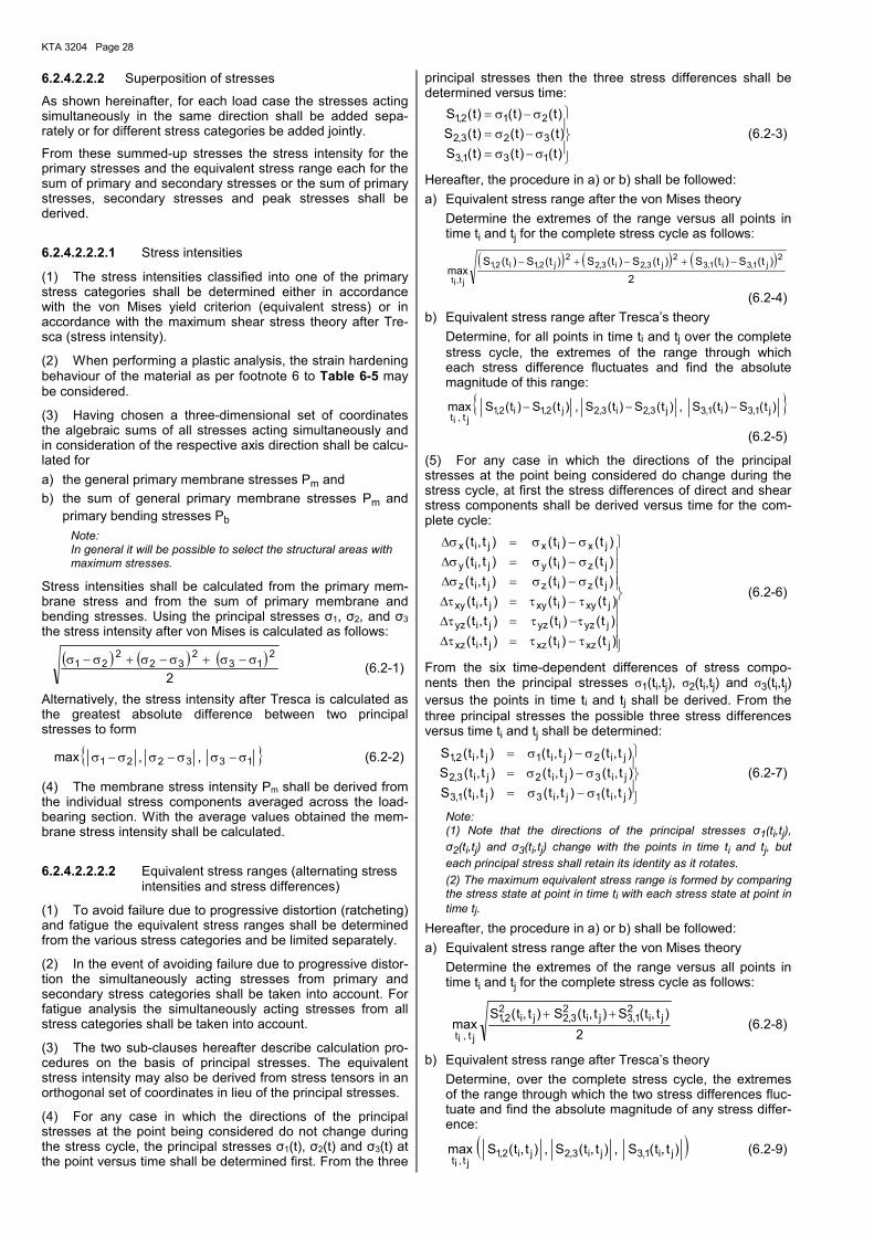
6.2.4.2.2.2 Superposition of stresses
As shown hereinafter, for each load case the stresses acting simultaneously in the same direction shall be added sepa-rately or for different stress categories be added jointly.
From these summed-up stresses the stress intensity for the primary stresses and the equivalent stress range each for the sum of primary and secondary stresses or the sum of primary stresses, secondary stresses and peak stresses shall be derived.
6.2.4.2.2.2.1 Stress intensities
(1) The stress intensities classified into one of the primary stress categories shall be determined either in accordance with the von Mises yield criterion (equivalent stress) or in accordance with the maximum shear stress theory after Tre-sca (stress intensity).
(2) When performing a plastic analysis, the strain hardening behaviour of the material as per footnote 6 to Table 6-5 may be considered.
(3) Having chosen a three-dimensional set of coordinates the algebraic sums of all stresses acting simultaneously and in consideration of the respective axis direction shall be calcu-lated for a) the general primary membrane stresses Pm and b) the sum of general primary membrane stresses Pm and
primary bending stresses Pb Note: In general it will be possible to select the structural areas with maximum stresses.
Stress intensities shall be calculated from the primary mem-brane stress and from the sum of primary membrane and bending stresses. Using the principal stresses σ1, σ2, and σ3 the stress intensity after von Mises is calculated as follows:
( ) ( ) ( )2
213
232
221 σ−σ+σ−σ+σ−σ (6.2-1)
Alternatively, the stress intensity after Tresca is calculated as the greatest absolute difference between two principal stresses to form
max { }133221 ,, σ−σσ−σσ−σ (6.2-2)
(4) The membrane stress intensity Pm shall be derived from the individual stress components averaged across the load-bearing section. With the average values obtained the mem-brane stress intensity shall be calculated.
6.2.4.2.2.2.2 Equivalent stress ranges (alternating stress intensities and stress differences)
(1) To avoid failure due to progressive distortion (ratcheting) and fatigue the equivalent stress ranges shall be determined from the various stress categories and be limited separately.
(2) In the event of avoiding failure due to progressive distor-tion the simultaneously acting stresses from primary and secondary stress categories shall be taken into account. For fatigue analysis the simultaneously acting stresses from all stress categories shall be taken into account.
(3) The two sub-clauses hereafter describe calculation pro-cedures on the basis of principal stresses. The equivalent stress intensity may also be derived from stress tensors in an orthogonal set of coordinates in lieu of the principal stresses.
(4) For any case in which the directions of the principal stresses at the point being considered do not change during the stress cycle, the principal stresses σ1(t), σ2(t) and σ3(t) at the point versus time shall be determined first. From the three
principal stresses then the three stress differences shall be determined versus time:
σ−σ=σ−σ=σ−σ=
)t()t()t(S)t()t()t(S)t()t()t(S
131,3
323,2
212,1 (6.2-3)
Hereafter, the procedure in a) or b) shall be followed: a) Equivalent stress range after the von Mises theory Determine the extremes of the range versus all points in
time ti and tj for the complete stress cycle as follows:
( ) ( ) ( )2
)t(S)t(S)t(S)t(S)t(S)t(Smax
2j1,3i1,3
2j3,2i3,2
2j2,1i2,1
jt,it
−+−+−
(6.2-4) b) Equivalent stress range after Tresca�s theory Determine, for all points in time ti and tj over the complete
stress cycle, the extremes of the range through which each stress difference fluctuates and find the absolute magnitude of this range:
{ })t(S)t(S,)t(S)t(S,)t(S)t(Smax j1,3i1,3j3,2i3,2j2,1i2,1jt,it
−−−
(6.2-5)
(5) For any case in which the directions of the principal stresses at the point being considered do change during the stress cycle, at first the stress differences of direct and shear stress components shall be derived versus time for the com-plete cycle:
τ−τ=τ∆τ−τ=τ∆τ−τ=τ∆σ−σ=σ∆σ−σ=σ∆σ−σ=σ∆
)t()t()t,t()t()t()t,t()t()t()t,t()t()t()t,t()t()t()t,t()t()t()t,t(
jxzixzjixz
jyziyzjiyz
jxyixyjixy
jzizjiz
jziyjiy
jxixjix
(6.2-6)
From the six time-dependent differences of stress compo-nents then the principal stresses σ1(ti,tj), σ2(ti,tj) and σ3(ti,tj) versus the points in time ti and tj shall be derived. From the three principal stresses the possible three stress differences versus time ti and tj shall be determined:
σ−σ=σ−σ=σ−σ=
)t,t()t,t()t,t(S)t,t()t,t()t,t(S)t,t()t,t()t,t(S
ji1ji3ji1,3
ji3ji2ji3,2
ji2ji1ji2,1 (6.2-7)
Note: (1) Note that the directions of the principal stresses σ1(ti,tj), σ2(ti,tj) and σ3(ti,tj) change with the points in time ti and tj, but each principal stress shall retain its identity as it rotates. (2) The maximum equivalent stress range is formed by comparing the stress state at point in time ti with each stress state at point in time tj.
Hereafter, the procedure in a) or b) shall be followed: a) Equivalent stress range after the von Mises theory Determine the extremes of the range versus all points in
time ti and tj for the complete stress cycle as follows:
2
)t,t(S)t,t(S)t,t(Smax ji
21,3ji
23,2ji
22,1
jt,it
++ (6.2-8)
b) Equivalent stress range after Tresca�s theory Determine, over the complete stress cycle, the extremes
of the range through which the two stress differences fluc-tuate and find the absolute magnitude of any stress differ-ence:
( ))t,t(S,)t,t(S,)t,t(Smax ji1,3ji3,2ji2,1jt,it
(6.2-9)
KTA 3204 Page 29
6.2.4.2.2.3 Limitation of stress intensities and equivalent stress ranges for all parts except threaded structural fasteners
(1) The stress intensities and equivalent stress ranges shall be limited in dependence of the mechanical behaviour of the material and the service loading level in accordance with Table 6-5.
(2) For welded joints to section 6.1.6 a) the allowable values of Table 6-5 shall be multiplied with
the weld factor n of Table 6-1 for primary stresses only, b) the fatigue strength reduction factor f of Table 6-1 and the
design fatigue curves to Figures 6-3 and 6-4 shall be used for fatigue analysis.
(3) The limits fixed in Table 6-5 only apply to full rectangular sections. For other sections the shape factors shall be fixed in dependence of the respective load behaviour.
(4) In the case of stress intensities derived from primary stresses and of equivalent stress ranges derived from primary and secondary stresses the limitation shall be based on the stress intensity factor Sm, strain limit Rp0.2 or tensile strength Rm minimum values. The Sm value is obtained on the basis of the respective temperature T at the point of the respective component under consideration versus time and the room temperature RT.
(5) Taking these assignments into account, the Sm value for austenitic materials and nickel alloys is derived as follows:
=7.2
R;3
R;1.1
R;
5.1R
.minS mTmRTT2.0pRT2.0pm (6.2-10)
(6) The minimum values for strain limit or tensile strength shall be taken from Section 7. These values shall be interpo-lated for certain temperatures T and be extrapolated up to a maximum of 425 °C. The Sm value above 40°C may exceed 0.67 ⋅ Rp0.2RT and reach a maximum of 0,9 ⋅ Rp0.2T. This cor-responds to a maximum permanent strain of 0.1 %. If this strain assigned to this stress value cannot be permitted, the Sm value shall be reduced such that only allowable deforma-tions can occur. To achieve this only the multiplication factors of Table B-1 and the Rp0.2T values according to Section 7 shall be used.
(7) The equivalent stress ranges derived from primary, sec-ondary and peak stresses shall be limited by means of fatigue analysis.
6.2.4.2.2.4 Requirements for loading levels A and B (1) The stipulations of clause 6.2.4.2.2.7 may be used in addition to those of Table 6-5.
(2) The given deformation limits assigned to loading levels A and B shall be satisfied.
(3) In addition to the limits of Table 6-5 the following re-quirements shall be considered:
a) Limitation of expansion stress intensity The allowable value of the maximum range of expansion
stress intensity when combined with all other primary and secondary stress intensities shall be 3 ⋅ Sm.
b) Thermal Stress Ratcheting Under certain combinations of steady state and cyclic
loadings there is a possibility of large distortions develop-ing as a result of thermal stress ratcheting, that is the de-formation increases by a nearly equal amount for each cy-cle. Examples of this phenomenon are treated in the fol-lowing and in clause 6.2.4.2.2.7.4. Thermal stress ratche-
ting can be analyzed by means of a plastic analysis and be evaluated in accordance with clause 6.2.4.2.2.8 (2). In the following, an example is given for the prevention of ratcheting in an axisymmetric shell loaded by internal pressure difference. The limiting value of maximum cyclic thermal stress in order to prevent cyclic growth in diameter is as follows:
Let y´ = maximum allowable range of thermal stress computed
on an elastic basis divided by the proof stress Rp0.2T or by 1.5 ⋅ Sm if this value exceeds Rp0.2T.
x = maximum general membrane stress due to pressure difference divided by the proof stress Rp0.2T or by 1.5 ⋅ Sm if this value exceeds Rp0.2T.
Case 1: Linear variation of temperature through the wall
y´ =x1 for 0 < x ≤ 0.5 (6.2-11)
y´ = 4 ⋅ (1 - x) for 0.5 < x < 1.0 (6.2-12)
Case 2: Parabolic constantly increasing or constantly decreasing variation of temperature through the wall
y´ = 5.2 ⋅ (1 - x) for 0.615 ≤ x < 1.0 (6.2-13) For x < 0.615 the following applies: x = 0.3; 0.4; 0.5 y´ = 4.65; 3.55; 2.70
The use of the proof stress Rp0.2T in the above relations instead of the proportional limit allows a small amount of growth during each cycle until strain hardening raises the proportional limit to Rp0.2T. If the proof stress of the mate-rial is higher than the endurance limit of the material, the latter value shall be used if there is to be a large number of cycles because strain softening may occur. For the de-termination of thermal stress ratcheting the endurance limit shall be taken as two times the Sa value at 1011 cy-cles in the applicable curve A of Figure 6-4.
6.2.4.2.2.5 Requirements for loading level C (1) In addition to the stipulations of Table 6-5 the following points shall be taken into account. Dynamic instability shall be considered in meeting the load, stress and deformation limits.
(2) The allowable values for the special stress limits shall not exceed 150 % of the values given in clauses 6.2.4.2.2.7 and 6.2.4.2.2.8 for this loading level.
(3) The limitation of the allowable stress intensity range composed of primary and secondary stresses need not be determined unless required for subpara (4).
(4) Loadings assigned to loading level C need not be con-sidered if it can be proved in accordance with clause 6.2.4.2.3.3.1 that a fatigue analysis is not required. Otherwise all loadings in loading level C shall be covered by the fatigue analysis according to clause 6.2.4.2.3.
(5) The given deformation limits assigned to loading level C shall be satisfied.
6.2.4.2.2.6 Requirements for loading level D
(1) For the limitation of loadings assigned to loading level D the stipulations of clauses 6.2.4.2.2.6.1 to 6.2.4.2.2.6.4 may be used.
(2) Where the special stress limits to clause 6.2.4.2.2.7 are applicable for loading level D limits, the calculated stresses shall not exceed twice the stress limits given in clause 6.2.4.2.2.7 as applied for level A and level B service limits.
KTA 3204 Page 30
6.2.4.2.2.6.1 Plastic analyses
(1) Plastic analysis is a method used to calculate the struc-tural response under given loads e.g. the material strain har-dening behaviour, effects of deformation rate, permanent deformations, and redistribution of stresses in the structure are considered.
Note: Plastic analysis mainly differs from the limit load analysis by the fact that in plastic analysis the actual material strain hardening behaviour is taken into account.
(2) The true stress/strain curve shall be adapted such that it corresponds to the values given in Section 7 for the respec-tive temperatures. This curve must be referred to and justified in the verification of structural integrity. The effects of the deformation rate on the yield curve shall also be considered.
(3) The yield criteria and the related law of material yielding used for performing a plastic analysis can be either assigned to the theory of Tresca or the theory of von Mises.
(4) A plastic analysis may be used to determine the collapse load Pc for a given combination of loadings on a structure. The limit load shall not be reached before the deformation has reached twice the value calculated for the first deviation from linear behaviour. In evaluating the analysis the calculation shall be interpreted such that it corresponds to the evaluation of the experiment (see clause 6.2.4.3). If the interpretation is made in such a way the collapse load obtained from plastic analysis shall be limited to satisfy the rules of the limit analy-sis (see clause 6.2.4.2.6).
(5) A plastic analysis may be used to determine the plastic instability load for a given combination of loading on a struc-ture. The plastic instability load is a load at which unbound plastic deformation occurs or where the ratio of force to de-formation shows a horizontal tangent. PI denominates the load at which plastic instability occurs.
(6) A plastic analysis may be used to determine the load or combination of loads which initiates strain at a location of specific interest. Where the strain has been limited the load causing this limiting strain is designated as Ps.
6.2.4.2.2.6.2 Analysis procedure
(1) System analysis For the purpose of system analysis a system is a specific component group selected from the overall facility, which has to be analyzed as a whole such that no essential coupling factors are neglected. For RPV internals system analysis means the analysis of the reactor coolant pressure boundary or part of it where all forces will be determined for the purpose of component stress analysis. Generally the system analysis is a dynamic analysis.
Note: According to the state-of-the-art the system analysis is performed on an elastic basis.
Where inelastic deformations occur that cannot be neglected, the originally elastic system analysis shall be modified. If required, an inelastic system analysis will become necessary. Therefore, the type of system analysis, whether elastic or inelastic, and the related forces in the component shall be reported in the stress analysis.
(2) Component analysis Each of the methods described under a) through e) may be used to calculate the loading levels assigned to level D ser-vice limits. However, the restrictions of the methods as per 6.2.4.2.2.6.3 and 6.2.4.2.2.6.4 shall be considered: a) elastic analysis, b) determination of collapse load by plastic analysis,
c) determination of plastic instability load or stress produced due to limited strain by plastic analysis,
d) determination of the loading or stress for the limiting strain by plastic analysis,
e) inelastic analysis by plastic analysis. The limitation of the primary stress intensity or the allowable loadings as per clauses 6.2.4.2.2.6.3 and 6.2.4.2.2.6.4 is shown in Table 6-6.
6.2.4.2.2.6.3 Limitation of primary stress intensity or al-lowable loadings
(1) Elastic system analysis and elastic component analysis The primary membrane stress intensity shall be limited to the lesser value of 2.4 ⋅ Sm or 0,7 ⋅ RmT. The values for RmT shall be taken from Section 7. The primary membrane plus bending stress intensity shall be limited to the lesser value of 3.6 ⋅ Sm or 1.0 ⋅ RmT.
(2) Elastic system analysis and analysis of component col-lapse load
The loadings assigned to the level D service limits shall be less than 100 % of the collapse load in which case the col-lapse load shall either be determined by a limit analysis to clause 6.2.4.2.6 or plastic analysis to clause 6.2.4.2.2.6.1 a) or by experiment to clause 6.2.4.3.1 a). When applying the limit analysis, the stipulations of clause 6.2.4.2.6 and especially those of section B 2 c) shall be con-sidered. Where deformation limits are adhered to, that part of the component to which these limitations apply shall not be evaluated by this method.
(3) Elastic system analysis and stress ratio method for the component
Here the rules of clause 6.2.4.2.7 and especially of Section C 3.2 apply.
(4) Elastic system analysis and analysis of plastic instability load or analysis of loading for component strain limita-tion
This combination of system and component analysis is not permitted.
(5) Elastic system analysis and inelastic component analysis
The primary membrane stress intensity shall be limited to 0.7 ⋅ RmT. The primary membrane plus bending stress inten-sity shall be equal to or smaller than the greater value of
0.7 ⋅ RmTt or ( )T2.0pmTtT2.0p RR31R −⋅+
where RmTt is the respective value from the true stress/strain curve at temperature T, i.e. the ultimate tensile load is to be applied on the true section and not on the initial section of the specimen. In such case, the elastic system analysis should be reviewed and the plastic deformation of the component be accounted for.
6.2.4.2.2.6.4 Limitation of primary stress intensity or al-lowable loading in inelastic analysis
(1) Inelastic system analysis and elastic component analysis
The primary membrane stress intensity shall be equal to or smaller than the greater value of
0.7 ⋅ RmT or ( )T2.0pmTT2.0p RR31R −⋅+
KTA 3204 Page 31
The primary membrane plus bending stress intensity shall be equal to or smaller than
1.0 ⋅ RmT or ( )T2.0pmTT2.0p RR21R
23
−⋅+⋅
(2) Inelastic system analysis and limit analysis of the component
This analysis may be performed in consideration of the rules of 6.2.4.2.2.6.3 (2).
(3) Inelastic system analysis and stress ratio analysis for the component
This analysis may be used in consideration of the rules of 6.2.4.2.2.6.3 (3).
(4) Inelastic system analysis and analysis of plastic instability load of the component
The loadings applied shall be equal to or smaller than 70 % of the loading to obtain plastic instability load PI or 100 % of the loading causing a membrane stress intensity with a value of
( )T2.0pIT2.0p RS31R −⋅+
where SI is the effective stress causing plastic instability.
(5) Inelastic system analysis and analysis of the loading for the limiting strain of the component
This analysis may be used if the loadings applied are smaller than the loadings which must satisfy the rules of (4), and if the loadings do not exceed 100 % of the loadings assigned to the limiting strain SS.
(6) Inelastic system analysis and inelastic component analysis
The primary membrane plus bending stress intensity shall be equal to or smaller than the greater value of
0.7 ⋅ RmT or ( )T2.0pmTT2.0p RR31R −⋅+
The primary membrane stress intensity shall be equal to or smaller than the greater value of
1.,0 ⋅ RmT or ( )T2.0pmTT2.0p RR21R
23
−⋅+⋅
6.2.4.2.2.7 Special stress limits
6.2.4.2.2.7.1 General requirements
(1) The following deviations from the basic stress limits are provided to cover special service loadings or configurations. Some of these deviations are more restrictive and some are less restrictive than the basic stress limits. Rules governing application of these special stress limits for level C and level D service limit applications are contained in clauses 6.2.4.2.2.5 (1) and 6.2.4.2.2.6, respectively.
(2) In cases of conflict between these requirements and the basic stress limits, the rules of this clause take precedence for the particular situations to which they apply. This clause does not apply to threaded structural fasteners to clause 6.2.4.1 a).
6.2.4.2.2.7.2 Bearing loads
(1) The average bearing stress for resistance to crushing under the maximum load, experienced as a result of loadings for which level A and B limits are designated shall be equal to or smaller than Rp0.2T except that when the distance to a free edge is larger than the distance over which the bearing load is applied, a stress of 1.5 ⋅ Rp0.2T is permitted. For clad surfaces the yield strength of the base metal may be used if, when calculating the bearing stress, the bearing area
is taken as the lesser of the actual contact area or the area of the base metal supporting the contact surface.
(2) Where required with regard to the point of load applica-tion (e.g. bearing loads applied near free edges), the possibil-ity of shear failure shall be considered. In the case of load stress only, the average shear stress shall be limited to 0,6 ⋅ Sm. In the case of load stress plus secondary stress, the average shear stress shall not exceed the limit values of a) or b) be-low. a) For a material whose Sm value above 40 °C exceeds
0,67 ⋅ Rp0.2T and may reach a maximum of 0,9 ⋅ Rp0.2T the smaller value of 0.5 ⋅ Rp0.2 at 40 °C or 0.67 ⋅ Rp0.2T shall be taken. This corresponds to a permanent strain of not more than 0.1 %. If the strain assigned to this stress value cannot be permitted, the Sm value shall be reduced such that only allowable deformation can occur. To achieve this the multiplication factors of Table B-1 and the Rp0.2T values according to Section 7 shall be used.
b) For other materials than listed in a) above the value 0.5 ⋅ Rp0.2T applies. For clad surfaces, if the configuration or thickness is such that a shear failure could occur en-tirely within the clad material, the allowable shear stress for the cladding shall be determined from the properties of the equivalent wrought material.
If the configuration is such that a shear failure could occur across a path that is partially base metal and partially clad material, the allowable shear stresses for each material shall be used when evaluating the combined resistance to this type of failure.
(3) When considering bearing stresses in pins and similar members, the elevated temperature proof stress Rp0.2T value is applicable, except that a value of 1.5 ⋅ Rp0.2T may be used if no credit is given to bearing area within one pin diameter from a plate edge.
6.2.4.2.2.7.3 Pure shear
(1) The average primary shear stress across a section loaded in pure shear, experienced as a result of loadings for which level A and B limits are designated (e.g. keys, shear rings), shall be limited to 0.6 ⋅ Sm.
(2) The maximum primary shear stress, experienced as a result of torsional loadings for which level A and B limits are designated exclusive of stress concentration at the periphery of a solid circular section in torsion, shall be limited to 0.8 ⋅ Sm.
(3) Primary plus secondary and peak shear stresses shall be converted to stress intensities (equal to two times pure shear stress) and as such shall not exceed the basic stress limits of Table 6-5. In addition, they shall meet the require-ments of 6.2.4.2.3.
6.2.4.2.2.7.4 Progressive distortion of non-integral con-nections
Screwed on caps, screwed in plugs, shear ring closures, and breechlock closures are examples of non-integral connections which are subject to failure by bell mouthing or other types of progressive deformation. If any combination of applied loads produces yielding, such joints are subject to ratcheting be-cause the mating members may become loose at the end of each complete operating cycle and start the next cycle in a new relationship with each other, with or without manual ma-nipulation. Additional distortion may occur in each cycle so that interlocking parts, such as threads, can eventually lose engagement. Therefore, primary plus secondary stress inten-
KTA 3204 Page 32
sities which result in slippage between the parts of a non-integral connection in which disengagement could occur as a result of progressive distortion shall be limited to the value Rp0.2T.
6.2.4.2.2.7.5 Triaxial stresses
The algebraic sum of the three primary principal stresses (σ1 + σ2 + σ3) shall not exceed four times the tabulated value of Sm.
6.2.4.2.2.7.6 Application of elastic analysis for stresses beyond the proof stress Rp0.2
(1) Certain of the allowable stresses permitted in the design criteria are such that the maximum stress calculated on an elastic basis may exceed the proof stress of the material.
(2) The limit on primary plus secondary stress intensity of 3 ⋅ Sm has been placed at a level which assures shakedown to elastic action after a few repetitions of the stress cycle except in regions containing significant local structural discon-tinuities or local thermal stresses. These last two factors are considered only in the performance of a fatigue evaluation. Therefore: a) in evaluating stresses for comparison with the stress limits
on other than fatigue allowables, stresses shall be calcu-lated on an elastic basis;
b) in evaluating stresses for comparison with fatigue allow-ables, all stresses except those which result from local thermal stresses shall be evaluated on an elastic basis. In evaluating local thermal stresses, the elastic equations shall be used except that the numerical value substituted for Poisson�s ratio shall be determined from the expres-sion:
⋅−
=ν
3.0S
R2.05.0
.max a
T2.0p (6.2-14)
where: Rp0.2T Proof stress Rp0.2 of the material at temperature T Sa Value obtained from the design fatigue curves for
the specified number of load cycles
T = 0.25 · T(
+ 0.75 · T� (6.2-15) with
T� maximum temperature at the considered load cycle
T(
minimum temperature at the considered load cycle
6.2.4.2.2.8 Application of plastic analysis
(1) The following subparagraphs provide guidance in the application of plastic analysis and some relaxation of the basic stress limits which are allowed if plastic analysis is used.
(2) The limits on primary plus secondary stress intensity (see Table 6-5), the thermal stress ratcheting as per clause 6.2.4.2.2.4 b) and progressive distortion of non-integral con-nections as per clause 6.2.4.2.2.7.4 need not be satisfied at a specific location if, at the location, the procedures of a) through c) below are used: a) in evaluating stresses for comparison with the remaining
stress limits, the stresses are calculated on an elastic ba-sis,
b) In lieu of satisfying the specific requirements of Table 6-5 as well as clauses 6.2.4.2.2.4 b) and 6.2.4.2.2.7.4 at a specific location, the structural action is calculated on an
elastic-plastic basis, and the design shall be considered to be acceptable if shakedown occurs (as opposed to con-tinuing deformation) and if the deformations which occur prior to shakedown do not exceed specified limits. How-ever, this shakedown requirement need not be satisfied provided the following 5 conditions are met:
ba) The requirements on the limitation of primary plus secondary stress intensity to Table 6-5 need not be satisfied at a specific location, provided that at the lo-cation the evaluation of stresses for comparison with all the other allowable values specified in 6.2.4.2.2.3 is calculated on an elastic basis.
This shall also apply where it is verified that failure due to thermal stress ratcheting in shells (clause 6.2.4.2.2.4 (3) b) and due to progressive distortion of non-integral connections (clause 6.2.4.2.2.7.4) will not occur.
This rule does not apply to threaded structural faste-ners.
bb) The maximum accumulated strain at any point, as a result of cyclic operations to which plastic analysis is applied, does not exceed 5.0 %.
bc) The maximum deformations do not exceed specified limits.
bd) In evaluating stresses for comparison with fatigue al-lowables, the numerically maximum principal total strain range shall be shall be multiplied by one-half the modulus of elasticity of the material (see Sec-tion 7) at the mean value of temperature of the cycle.
be) The material shall have an elastic ratio of less than 0.8.
c) In evaluating stresses for comparison with fatigue allow-ables (Sa) , the numerically maximum principal total strain range which occurs after shakedown shall be multiplied by on-half of the modulus of elasticity of the material (Section 7) at the mean value of the temperature of the cycle.
6.2.4.2.2.9 Limitation of stress intensity and equivalent stress range for threaded structural fasteners
6.2.4.2.2.9.1 General requirements
(1) The rules of this clause apply to threaded structural fasteners for RPV internals as per clause 6.2.4.1 a). The specific stress limits of clause 6.2.4.2.2.7 shall not be used for threaded structural fasteners.
(2) For each service loading level the stress intensities and equivalent stress ranges shall be limited in dependence of the mechanical behaviour of the material in accordance with Ta-ble 6-7 and in accordance with the requirements of clause 6.2.4.2.2.9.2 regarding loading levels A and B, clause 6.2.4.2.2.9.3 regarding loading level C and clause 6.2.4.2.2.9.4 regarding loading level D. The stress intensities and equivalent stress ranges derived from primary stresses and from primary and secondary stresses shall be limited based on the stress intensity factor Sm in accordance with clause 6.2.4.2.2.3 or based on the proof stress Rp0.2T in ac-cordance with Section 7.
(3) The equivalent stress ranges derived from primary, sec-ondary and peak stresses shall be limited by means of fatigue analysis.
6.2.4.2.2.9.2 Level A and B service limits
The total axial load transferred through the fastener threads shall not go to or through zero during the specified service loadings. If a tight joint is required to be provided by threaded fasteners, sufficient residual preload shall be provided.
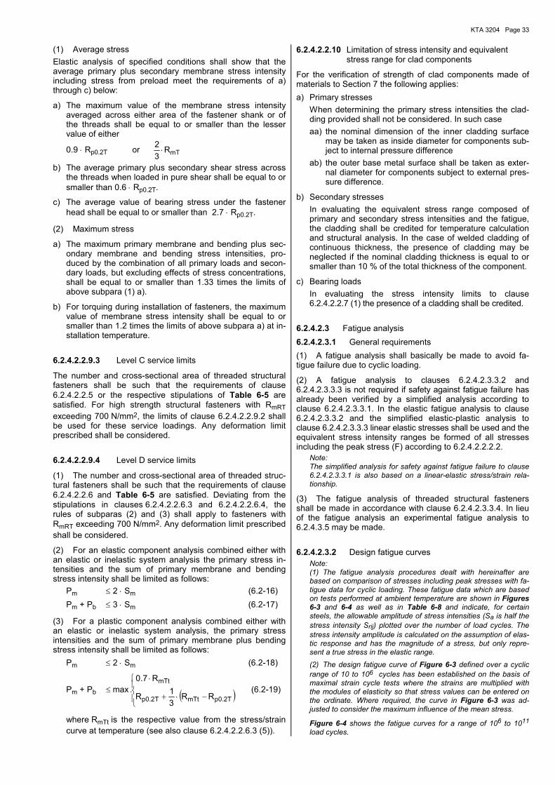
KTA 3204 Page 33
(1) Average stress Elastic analysis of specified conditions shall show that the average primary plus secondary membrane stress intensity including stress from preload meet the requirements of a) through c) below:
a) The maximum value of the membrane stress intensity averaged across either area of the fastener shank or of the threads shall be equal to or smaller than the lesser value of either
0.9 ⋅ Rp0.2T or mTR32
⋅
b) The average primary plus secondary shear stress across the threads when loaded in pure shear shall be equal to or smaller than 0.6 ⋅ Rp0.2T.
c) The average value of bearing stress under the fastener head shall be equal to or smaller than 2.7 ⋅ Rp0.2T.
(2) Maximum stress
a) The maximum primary membrane and bending plus sec-ondary membrane and bending stress intensities, pro-duced by the combination of all primary loads and secon-dary loads, but excluding effects of stress concentrations, shall be equal to or smaller than 1.33 times the limits of above subpara (1) a).
b) For torquing during installation of fasteners, the maximum value of membrane stress intensity shall be equal to or smaller than 1.2 times the limits of above subpara a) at in-stallation temperature.
6.2.4.2.2.9.3 Level C service limits
The number and cross-sectional area of threaded structural fasteners shall be such that the requirements of clause 6.2.4.2.2.5 or the respective stipulations of Table 6-5 are satisfied. For high strength structural fasteners with RmRT exceeding 700 N/mm2, the limits of clause 6.2.4.2.2.9.2 shall be used for these service loadings. Any deformation limit prescribed shall be considered.
6.2.4.2.2.9.4 Level D service limits
(1) The number and cross-sectional area of threaded struc-tural fasteners shall be such that the requirements of clause 6.2.4.2.2.6 and Table 6-5 are satisfied. Deviating from the stipulations in clauses 6.2.4.2.2.6.3 and 6.2.4.2.2.6.4, the rules of subparas (2) and (3) shall apply to fasteners with RmRT exceeding 700 N/mm2. Any deformation limit prescribed shall be considered.
(2) For an elastic component analysis combined either with an elastic or inelastic system analysis the primary stress in-tensities and the sum of primary membrane and bending stress intensity shall be limited as follows: Pm ≤ 2 ⋅ Sm (6.2-16) Pm + Pb ≤ 3 ⋅ Sm (6.2-17)
(3) For a plastic component analysis combined either with an elastic or inelastic system analysis, the primary stress intensities and the sum of primary membrane plus bending stress intensity shall be limited as follows: Pm ≤ 2 ⋅ Sm (6.2-18)
Pm + Pb ( )
−⋅+
⋅≤
T2.0pmTtT2.0p
mTt
RR31R
R7.0.max (6.2-19)
where RmTt is the respective value from the stress/strain curve at temperature (see also clause 6.2.4.2.2.6.3 (5)).
6.2.4.2.2.10 Limitation of stress intensity and equivalent stress range for clad components
For the verification of strength of clad components made of materials to Section 7 the following applies: a) Primary stresses When determining the primary stress intensities the clad-
ding provided shall not be considered. In such case aa) the nominal dimension of the inner cladding surface
may be taken as inside diameter for components sub-ject to internal pressure difference
ab) the outer base metal surface shall be taken as exter-nal diameter for components subject to external pres-sure difference.
b) Secondary stresses In evaluating the equivalent stress range composed of
primary and secondary stress intensities and the fatigue, the cladding shall be credited for temperature calculation and structural analysis. In the case of welded cladding of continuous thickness, the presence of cladding may be neglected if the nominal cladding thickness is equal to or smaller than 10 % of the total thickness of the component.
c) Bearing loads In evaluating the stress intensity limits to clause
6.2.4.2.2.7 (1) the presence of a cladding shall be credited.
6.2.4.2.3 Fatigue analysis 6.2.4.2.3.1 General requirements (1) A fatigue analysis shall basically be made to avoid fa-tigue failure due to cyclic loading.
(2) A fatigue analysis to clauses 6.2.4.2.3.3.2 and 6.2.4.2.3.3.3 is not required if safety against fatigue failure has already been verified by a simplified analysis according to clause 6.2.4.2.3.3.1. In the elastic fatigue analysis to clause 6.2.4.2.3.3.2 and the simplified elastic-plastic analysis to clause 6.2.4.2.3.3.3 linear elastic stresses shall be used and the equivalent stress intensity ranges be formed of all stresses including the peak stress (F) according to 6.2.4.2.2.2.2.
Note: The simplified analysis for safety against fatigue failure to clause 6.2.4.2.3.3.1 is also based on a linear-elastic stress/strain rela-tionship.
(3) The fatigue analysis of threaded structural fasteners shall be made in accordance with clause 6.2.4.2.3.3.4. In lieu of the fatigue analysis an experimental fatigue analysis to 6.2.4.3.5 may be made.
6.2.4.2.3.2 Design fatigue curves Note: (1) The fatigue analysis procedures dealt with hereinafter are based on comparison of stresses including peak stresses with fa-tigue data for cyclic loading. These fatigue data which are based on tests performed at ambient temperature are shown in Figures 6-3 and 6-4 as well as in Table 6-8 and indicate, for certain steels, the allowable amplitude of stress intensities (Sa is half the stress intensity Srij) plotted over the number of load cycles. The stress intensity amplitude is calculated on the assumption of elas-tic response and has the magnitude of a stress, but only repre-sent a true stress in the elastic range. (2) The design fatigue curve of Figure 6-3 defined over a cyclic range of 10 to 106 cycles has been established on the basis of maximal strain cycle tests where the strains are multiplied with the modules of elasticity so that stress values can be entered on the ordinate. Where required, the curve in Figure 6-3 was ad-justed to consider the maximum influence of the mean stress.
Figure 6-4 shows the fatigue curves for a range of 106 to 1011 load cycles.
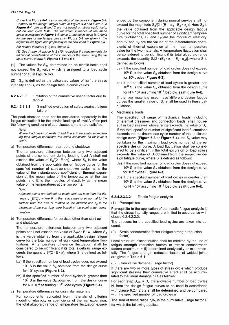
KTA 3204 Page 34
Curve A in Figure 6-4 is a continuation of the curve in Figure 6-3. Contrary to the design fatigue curve in Figure 6-3 and curve A in Figure 6-4, curves B and C are not based on strain cycle tests, but on load cycle tests. The maximum influence of the mean stress is indicated in Figure 6-4, curve C, but not in curve B. Criteria for the use of the fatigue curves in Figure 6-4 are given in the legend to this figure and graphically in the flow chart in Figure 6-5. For related literature [10] see Annex G. (3) See Annex H clause H 2 (15) regarding the requirements for additional consideration of the influence of the fluids using the fa-tigue curves shown in Figures 6-3 and 6-4.
(1) The values for Salt determined on an elastic basis shall not exceed the Sa value which is assigned to a load cycle number of 10 in Figure 6-3.
(2) Salt is defined as the calculated values of half the stress intensity and Sa as the design fatigue curve values.
6.2.4.2.3.3 Limitation of the cumulative usage factor due to fatigue
6.2.4.2.3.3.1 Simplified evaluation of safety against fatigue failure
The peak stresses need not be considered separately in the fatigue evaluation if for the service loadings of level A of the part the following conditions of sub-clauses a) to d) are satisfied.
Note: Where load cases of levels B and C are to be analysed regard-ing their fatigue behaviour, the same conditions as for level A apply.
a) Temperature difference - start-up and shutdown The temperature difference between any two adjacent
points of the component during loading level A shall not exceed the value of Sa/(2 · E · α), where Sa is the value obtained from the applicable design fatigue curve for the specified number of start-up-shutdown cycles, α is the value of the instantaneous coefficient of thermal expan-sion at the mean value of the temperatures at the two points, and E is the modulus of elasticity at the mean value of the temperatures at the two points.
Note: Adjacent points are defined as points that are less than the dis-tance csR2 ⋅⋅ , where R is the radius measured normal to the surface from the axis of rotation to the midwall and sc is the thickness of the part (e.g. core barrel) at the point under consi-deration.
b) Temperature difference for services other than start-up and shutdown
The temperature difference between any two adjacent points shall not exceed the value of Sa/2 · E · α, where Sa is the value obtained from the applicable design fatigue curve for the total number of significant temperature fluc-tuations. A temperature difference fluctuation shall be considered to be significant if its total algebraic range ex-ceeds the quantity S/(2 · E · α), where S is defined as fol-lows: ba) If the specified number of load cycles does not exceed
106 S is the value Sa obtained from the design curve for 106 cycles (Figure 6-3).
bb) If the specified number of load cycles is greater than 106 S is the value Sa obtained from the design curve for N > 106 assuming 1011 load cycles (Figure 6-4).
c) Temperature differences for dissimilar materials For components fabricated from materials of differing
moduli of elasticity or coefficients of thermal expansion, the total algebraic range of temperature fluctuation experi-
enced by the component during normal service shall not exceed the magnitude Sa/[2 · (E1 · α1 - E2 · α2)]. Here Sa is the value obtained from the applicable design fatigue curve for the total specified number of significant tempera-ture fluctuations, E1 and E2 are the moduli of elasticity, and α1 and α2 are the values of the instantaneous coeffi-cients of thermal expansion at the mean temperature value for the two materials. A temperature fluctuation shall be considered to be significant if its total algebraic range exceeds the quantity S/[2 · (E1 · α1 - E2 · α2)], where S is defined as follows: ca) If the specified number of load cycles does not exceed
106 S is the value Sa obtained from the design curve for 106 cycles (Figure 6-3).
cb) If the specified number of load cycles is greater than 106 S is the value Sa obtained from the design curve for N > 106 assuming 1011 load cycles (Figure 6-4).
If the two materials used have different design fatigue curves the smaller value of Sa shall be used in these cal-culations.
d) Mechanical loads The specified full range of mechanical loads, including
differential pressures and connection loads, shall not re-sult in load stresses whose range exceeds the value of Sa. If the total specified number of significant load fluctuations exceeds the maximum load cycle number of the applicable design curve (Figure 6-3 or Figure 6-4), the Sa value may be taken for the maximum load cycle number of the re-spective design curve. A load fluctuation shall be consid-ered to be significant if the total excursion of load stress exceeds the value of S obtained from the respective de-sign fatigue curve, where S is defined as follows: da) If the specified number of load cycles does not exceed
106 S is the value Sa obtained from the design curve for 106 cycles (Figure 6-3).
db) If the specified number of load cycles is greater than 106 S is the value Sa obtained from the design curve for N > 106 assuming 1011 load cycles (Figure 6-4).
6.2.4.2.3.3.2 Elastic fatigue analysis
(1) Prerequisites
Prerequisite to the application of the elastic fatigue analysis is that the stress intensity ranges are limited in accordance with clause 6.2.4.2.2.3. The stresses for the specified load cycles are taken into ac-count.
(2) Strain concentration factor (fatigue strength reduction factor)
Local structural discontinuities shall be credited by the use of fatigue strength reduction factors or stress concentration factors (maximum = 5) determined analytically or experimen-tally. The fatigue strength reduction factors of welded joints are given in Table 6-1.
(3) Cumulative damage (usage factor) If there are two or more types of stress cycle which produce significant stresses their cumulative effect shall be accumu-lated to the linear damage rule as follows: For each step Salt,i = Sa the allowable number of load cycles Ni from the design fatigue curves to be used in accordance with clause 6.2.4.2.3.2 shall be determined and be compared with the specified number of load cycles ni. The sum of these ratios ni/Ni is the cumulative usage factor D for which the following applies:
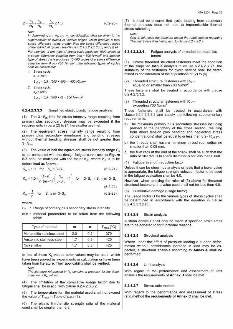
KTA 3204 Page 35
0.1Nn...
Nn
NnD
k
k
2
2
1
1 ≤++= (6.2-20)
Note: In determining n1, n2, n3, nn consideration shall be given to the superposition of cycles of various origins which produce a total stress difference range greater than the stress difference ranges of the individual cycles (see clause 6.2.4.2.2.2.2 (1) b) and (2) e). For example: if one type of stress cycle produces 1000 cycles of a stress difference variation from 0 to + 500 N/mm2 and another type of stress cycle produces 10.000 cycles of a stress difference variation from 0 to - 400 N/mm2 , the following types of cycles shall be considered: 1. Stress cycle: n1 = 1000
Salt1 = 0.5 ⋅ (500 + 400) = 450 N/mm2
2. Stress cycle: n2 = 9000
Salt2 = 0.5 ⋅ (400 + 0) = 200 N/mm2
6.2.4.2.3.3.3 Simplified elastic plastic fatigue analysis
(1) The 3 · Sm limit for stress intensity range resulting from primary plus secondary stresses may be exceeded if the requirements in para (2) to (7) hereinafter are met.
(2) The equivalent stress intensity range resulting from primary plus secondary membrane and bending stresses without thermal bending stresses shall be not greater than 3 · Sm.
(3) The value of half the equivalent stress intensity range Sa to be compared with the design fatigue curve acc. to Figure 6-3 shall be multiplied with the factor Ke , where Ke is to be determined as follows:
mne S3Sfor0.1K ⋅≤= (6.2-21)
( )( ) mnm
m
ne S3mSS3for1
S3S
1mnn10.1K ⋅⋅<<⋅
−
⋅⋅
−⋅−
+=
(6.2-22)
mne S3mSforn1K ⋅⋅≥= (6.2-23)
where Sn : Range of primary plus secondary stress intensity m,n : material parameters to be taken from the following
table:
Type of material m n Tmax (°C)
Martensitic stainless steel 2.0 0.2 370
Austenitic stainless steel 1.7 0.3 425
Nickel alloy 1.7 0.3 425 In lieu of these Ke values other values may be used, which have been proved by experiments or calculation or have been taken from literature. Their applicability shall be verified. Note: The literature referenced in [1] contains a proposal for the deter-
mination of Ke values.
(4) The limitation of the cumulative usage factor due to fatigue shall be in acc. with clause 6.2.4.2.3.3.2.
(5) The temperature for the material used shall not exceed the value of Tmax in Table of para (3).
(6) The elastic limit/tensile strength ratio of the material used shall be smaller than 0.8.
(7) It must be ensured that cyclic loading from secondary thermal stresses does not lead to impermissible thermal stress ratcheting.
Note: Only in this case the structure meets the requirements regarding Thermal Stress Ratcheting acc. to clause 6.2.4.2.2.4.
6.2.4.2.3.3.4 Fatigue analysis of threaded structural fas-teners
(1) Unless threaded structural fasteners meet the condition of the simplified fatigue analysis to clause 6.2.4.2.3.3.1, the suitability of the fasteners for cyclic service shall be deter-mined in consideration of the stipulations of (2) to (6).
(2) Threaded structural fasteners with RmRT equal to or smaller than 700 N/mm2
These fasteners shall be treated in accordance with clause 6.2.4.2.3.3.2.
(3) Threaded structural fasteners with RmRT exceeding 700 N/mm2
These fasteners shall be treated in accordance with clause 6.2.4.2.3.3.2 and satisfy the following supplementary requirements: a) The maximum primary plus secondary stresses including
preload at the periphery of the cross section (resulting from direct tension plus bending and neglecting stress concentrations) shall be equal to or less than 0.9 ⋅ Rp0.2T.
b) the threads shall have a minimum thread root radius no smaller than 0.08 mm.
c) the fillet radii at the end of the shank shall be such that the ratio of fillet radius to shank diameter is not less than 0.060.
(4) Fatigue strength reduction factor Unless it can be shown by analysis or tests that a lower value is appropriate, the fatigue strength reduction factor to be used in the fatigue evaluation shall be 4.0. However, when applying the rules of (3) above for threaded structural fasteners, the value used shall not be less than 4.0.
(5) Cumulative damage (usage factor) The usage factor D for the various types of stress cycles shall be determined in accordance with the equation in clause 6.2.4.2.3.3.2 (3).
6.2.4.2.4 Strain analysis
A strain analysis shall only be made if specified strain limits are to be adhered to for functional reasons.
6.2.4.2.5 Structural analysis
Where under the effect of pressure loading a sudden defor-mation without considerable increase in load may be ex-pected, a structural analysis according to Annex A shall be performed.
6.2.4.2.6 Limit analysis
With regard to the performance and assessment of limit analysis the requirements of Annex B shall be met.
6.2.4.2.7 Stress ratio method
With regard to the performance and assessment of stress ratio method the requirements of Annex C shall be met.
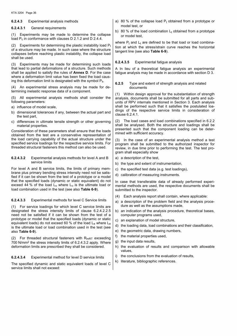
KTA 3204 Page 36
6.2.4.3 Experimental analysis methods
6.2.4.3.1 General requirements
(1) Experiments may be made to determine the collapse load Pc in conformance with clauses D 2.1.2 and D 2.4.4.
(2) Experiments for determining the plastic instability load PI of a structure may be made. In such case where the structure collapses before reaching plastic instability, the collapse load shall be used.
(3) Experiments may be made for determining such loads that lead to partial deformations of a structure. Such methods shall be applied to satisfy the rules of Annex D. For the case where a deformation limit value has been fixed the load caus-ing this deformation limit is designated with the symbol Ps.
(4) An experimental stress analysis may be made for de-termining inelastic response data of a component.
(5) All experimental analysis methods shall consider the following parameters: a) influence of model scale, b) dimensional tolerances if any, between the actual part and
the test part, c) differences in ultimate tensile strength or other governing
material properties. Consideration of these parameters shall ensure that the loads obtained from the test are a conservative representation of the load carrying capability of the actual structure under the specified service loadings for the respective service limits. For threaded structural fasteners this method can also be used.
6.2.4.3.2 Experimental analysis methods for level A and B service limits
For level A and B service limits, the limits of primary mem-brane plus primary bending stress intensity need not be satis-fied if it can be shown from the test of a prototype or a model that the specified loads (dynamic or static equivalent) do not exceed 44 % of the load Lu where Lu is the ultimate load or load combination used in the test (see also Table 6-9).
6.2.4.3.3 Experimental methods for level C Service limits
(1) For service loadings for which level C service limits are designated the stress intensity limits of clause 6.2.4.2.2.5 need not be satisfied if it can be shown from the test of a prototype or model that the specified loads (dynamic or static equivalent loads) do not exceed 60 % of the load Le where Le is the ultimate load or load combination used in the test (see also Table 6-9).
(2) For threaded structural fasteners with RmRT exceeding 700 N/mm2 the stress intensity limits of 6.2.4.3.2 apply. Where deformation limits are prescribed they shall be considered.
6.2.4.3.4 Experimental method for level D service limits
The specified dynamic and static equivalent loads of level C service limits shall not exceed:
a) 80 % of the collapse load Pt obtained from a prototype or model test, or
b) 80 % of the load combination Lt obtained from a prototype or model test,
where Pt and Lt are defined to be that load or load combina-tion at which the stress/strain curve reaches the horizontal tangent line (see also Table 6-9).
6.2.4.3.5 Experimental fatigue analysis
A In lieu of a theoretical fatigue analysis an experimental fatigue analysis may be made in accordance with section D 3.
6.2.5 Type and extent of strength analysis and related documents
(1) Within design approval for the substantiation of strength analysis, documents shall be submitted for all parts and sub-units of RPV internals mentioned in Section 3. Each analysis shall be performed such that it satisfies the postulated loa-dings of the respective service limits in consideration of clause 6.2.4.1.
(2) The load cases and load combinations specified in 6.2.2 shall be analysed. Both the structure and loadings shall be presented such that the component loading can be deter-mined with sufficient accuracy.
(3) In the case of an experimental analysis method a test program shall be submitted to the authorized inspector for review, in due time prior to performing the test. The test pro-gram shall especially show a) a description of the test, b) the type and extent of instrumentation, c) the specified test data (e.g. test loadings), d) calibration of measuring instruments.
In case that transferable data of already performed experi-mental methods are used, the respective documents shall be submitted to the inspector.
(4) Each analysis report shall contain, where applicable: a) a description of the problem field and the analysis proce-
dure as well as the assumptions made, b) an indication of the analysis procedure, theoretical bases,
computer programs used, c) an explanation of model structure, d) the loading data, load combinations and their classification, e) the geometric data, drawing numbers, f) the material properties used, g) the input data results, h) the evaluation of results and comparison with allowable
values, i) the conclusions from the evaluation of results, k) literature, bibliographic references.
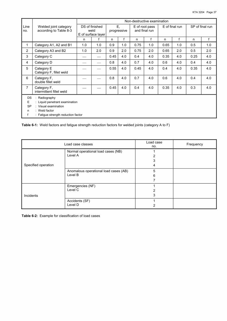
KTA 3204 Page 37
Non-destructive examination Line no.
Welded joint category according to Table 8-3
DS of finished weld
E of surface layer
E, progressive
E of root pass and final run
E of final run SP of final run
n f n f n f n f n f 1 Category A1, A2 and B1 1.0 1.0 0.9 1.0 0.75 1.0 0.65 1.0 0.5 1.0
2 Category A3 and B2 1.0 2.0 0.9 2.0 0.75 2.0 0.65 2.0 0.5 2.0
3 Category C 0.45 4.0 0.4 4.0 0.35 4.0 0.25 4.0
4 Category D 0.8 4.0 0.7 4.0 0.6 4.0 0.4 4.0
5 Category E Category F, fillet weld
0.55 4.0 0.45 4.0 0.4 4.0 0.35 4.0
6 Category F, double fillet weld
0.8 4.0 0.7 4.0 0.6 4.0 0.4 4.0
7 Category F, intermittent fillet weld
0.45 4.0 0.4 4.0 0.35 4.0 0.3 4.0
DS : Radiography E : Liquid penetrant examination SP : Visual examination n : Weld factor f : Fatigue strength reduction factor
Table 6-1: Weld factors and fatigue strength reduction factors for welded joints (category A to F)
Load case classes Load case no. Frequency
Specified operation
Normal operational load cases (NB) Level A
1 2 3 4
Anomalous operational load cases (AB) Level B
5 6 7
Incidents
Emergencies (NF) Level C
1 2 3
Accidents (SF) Level D
1 2
Table 6-2: Example for classification of load cases
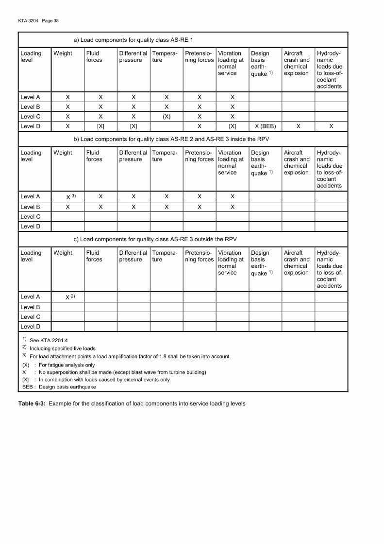
KTA 3204 Page 38
a) Load components for quality class AS-RE 1
Loading level
Weight Fluid forces
Differential pressure
Tempera-ture
Pretensio-ning forces
Vibration loading at normal service
Design basis earth-quake 1)
Aircraft crash and chemical explosion
Hydrody-namic loads due to loss-of-coolant accidents
Level A X X X X X X
Level B X X X X X X
Level C X X X (X) X X
Level D X [X] [X] X [X] X (BEB) X X
b) Load components for quality class AS-RE 2 and AS-RE 3 inside the RPV
Loading level
Weight Fluid forces
Differential pressure
Tempera-ture
Pretensio-ning forces
Vibration loading at normal service
Design basis earth-quake 1)
Aircraft crash and chemical explosion
Hydrody-namic loads due to loss-of-coolant accidents
Level A X 3) X X X X X
Level B X X X X X X
Level C
Level D
c) Load components for quality class AS-RE 3 outside the RPV
Loading level
Weight Fluid forces
Differential pressure
Tempera-ture
Pretensio-ning forces
Vibration loading at normal service
Design basis earth-quake 1)
Aircraft crash and chemical explosion
Hydrody-namic loads due to loss-of-coolant accidents
Level A X 2)
Level B
Level C
Level D
1) See KTA 2201.4 2) Including specified live loads 3) For load attachment points a load amplification factor of 1.8 shall be taken into account. (X) : For fatigue analysis only X : No superposition shall be made (except blast wave from turbine building) [X] : In combination with loads caused by external events only BEB : Design basis earthquake
Table 6-3: Example for the classification of load components into service loading levels
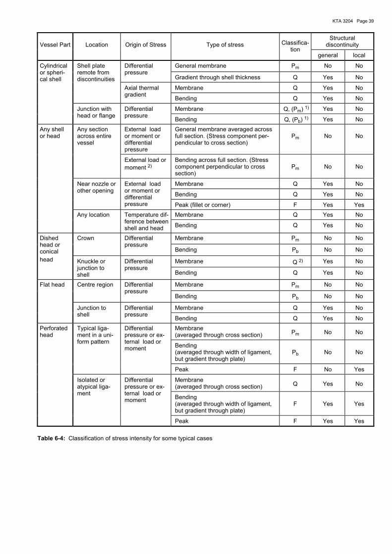
KTA 3204 Page 39
Vessel Part
Location
Origin of Stress
Type of stress
Structural discontinuity
Classifica-tion
general local
General membrane Pm No No Differential pressure
Gradient through shell thickness Q Yes No
Membrane Q Yes No
Shell plate remote from discontinuities
Axial thermal gradient Bending Q Yes No
Membrane Q, (Pm) 1) Yes No
Cylindrical or spheri-cal shell
Junction with head or flange
Differential pressure Bending Q, (Pb) 1) Yes No
External load or moment or differential pressure
General membrane averaged across full section. (Stress component per-pendicular to cross section)
Pm
No
No
Any section across entire vessel
External load or moment 2)
Bending across full section. (Stress component perpendicular to cross section)
Pm
No
No
Membrane Q Yes No
Bending Q Yes No
Any shell or head
Near nozzle or other opening
External load or moment or differential pressure Peak (fillet or corner) F Yes Yes
Membrane Q Yes No Any location Temperature dif-ference between shell and head Bending Q Yes No
Membrane Pm No No Crown Differential pressure
Bending Pb No No
Membrane Q 2) Yes No
Dished head or conical head Knuckle or
junction to shell
Differential pressure
Bending Q Yes No
Membrane Pm No No Centre region Differential pressure
Bending Pb No No
Membrane Q Yes No
Flat head
Junction to shell
Differential pressure Bending Q Yes No
Membrane (averaged through cross section) Pm No No
Bending (averaged through width of ligament, but gradient through plate)
Pb
No
No
Typical liga-ment in a uni-form pattern
Differential pressure or ex-ternal load or moment
Peak F No Yes
Membrane (averaged through cross section) Q Yes No
Bending (averaged through width of ligament, but gradient through plate)
F
Yes
Yes
Perforated head
Isolated or atypical liga-ment
Differential pressure or ex-ternal load or moment
Peak F Yes Yes
Table 6-4: Classification of stress intensity for some typical cases
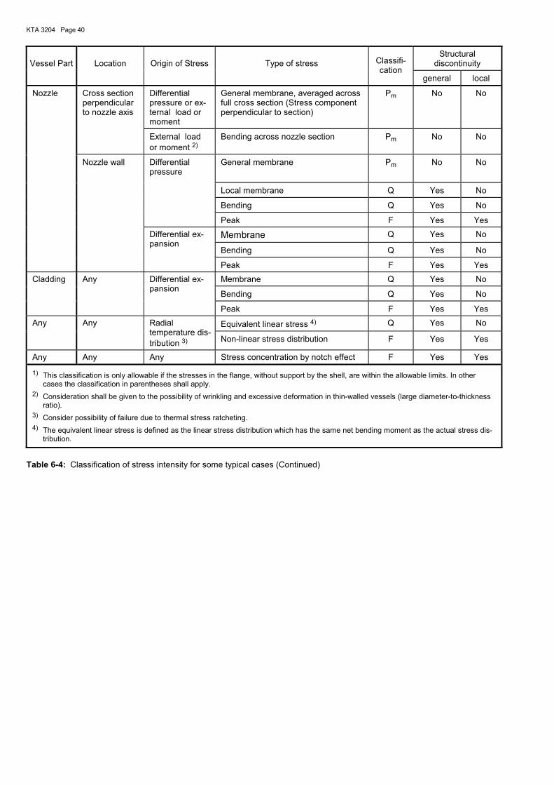
KTA 3204 Page 40
Vessel Part
Location
Origin of Stress
Type of stress
Structural discontinuity
Classifi-cation
general local
Cross section perpendicular to nozzle axis
Differential pressure or ex-ternal load or moment
General membrane, averaged across full cross section (Stress component perpendicular to section)
Pm No No
External load or moment 2)
Bending across nozzle section Pm No No
General membrane Pm No
No
Local membrane Q Yes No
Bending Q Yes No
Nozzle
Nozzle wall Differential pressure
Peak F Yes Yes
Membrane Q Yes No
Bending Q Yes No
Differential ex-pansion
Peak F Yes Yes
Membrane Q Yes No
Bending Q Yes No
Cladding Any Differential ex-pansion
Peak F Yes Yes
Equivalent linear stress 4) Q Yes No Any Any Radial temperature dis-tribution 3) Non-linear stress distribution F Yes Yes
Any Any Any Stress concentration by notch effect F Yes Yes
1) This classification is only allowable if the stresses in the flange, without support by the shell, are within the allowable limits. In other cases the classification in parentheses shall apply.
2) Consideration shall be given to the possibility of wrinkling and excessive deformation in thin-walled vessels (large diameter-to-thickness ratio).
3) Consider possibility of failure due to thermal stress ratcheting. 4) The equivalent linear stress is defined as the linear stress distribution which has the same net bending moment as the actual stress dis-
tribution.
Table 6-4: Classification of stress intensity for some typical cases (Continued)
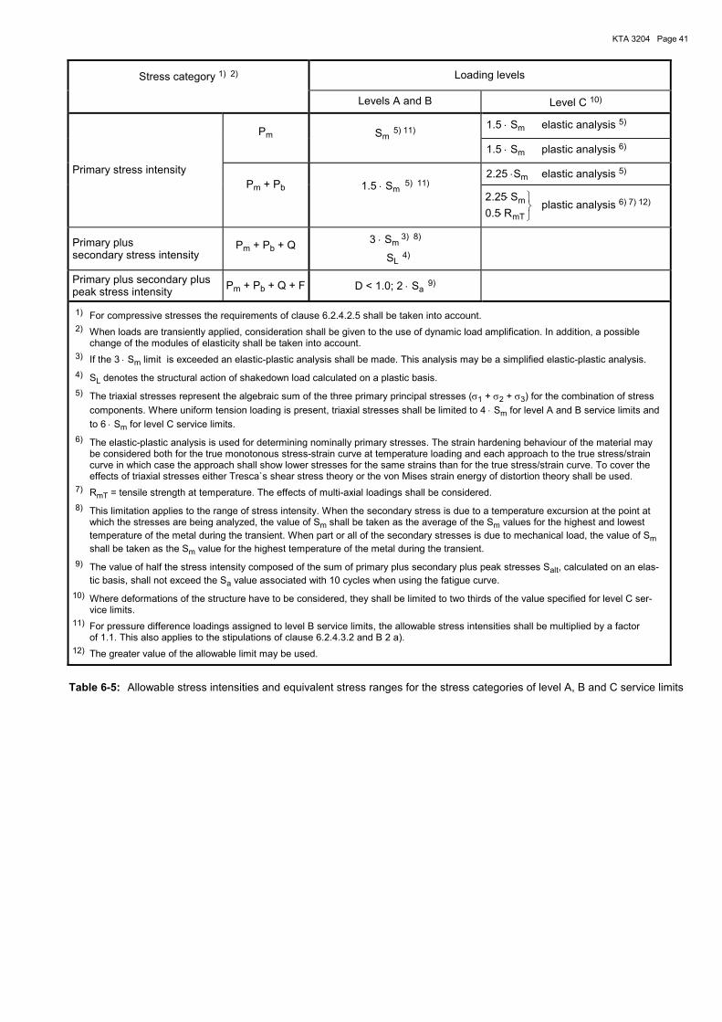
KTA 3204 Page 41
Stress category 1) 2) Loading levels
Levels A and B Level C 10)
1.5 ⋅ Sm elastic analysis 5) Pm Sm 5) 11) 1.5 ⋅ Sm plastic analysis 6)
2.25 ⋅Sm elastic analysis 5) Primary stress intensity Pm + Pb 1.5 ⋅ Sm 5) 11)
⋅⋅
mT
mR5.0
S25.2 plastic analysis 6) 7) 12)
Primary plus secondary stress intensity
Pm + Pb + Q 3 ⋅ Sm 3) 8)
SL 4)
Primary plus secondary plus peak stress intensity Pm + Pb + Q + F D < 1.0; 2 ⋅ Sa 9)
1) For compressive stresses the requirements of clause 6.2.4.2.5 shall be taken into account. 2) When loads are transiently applied, consideration shall be given to the use of dynamic load amplification. In addition, a possible
change of the modules of elasticity shall be taken into account. 3) If the 3 ⋅ Sm limit is exceeded an elastic-plastic analysis shall be made. This analysis may be a simplified elastic-plastic analysis. 4) SL denotes the structural action of shakedown load calculated on a plastic basis. 5) The triaxial stresses represent the algebraic sum of the three primary principal stresses (σ1 + σ2 + σ3) for the combination of stress
components. Where uniform tension loading is present, triaxial stresses shall be limited to 4 ⋅ Sm for level A and B service limits and to 6 ⋅ Sm for level C service limits.
6) The elastic-plastic analysis is used for determining nominally primary stresses. The strain hardening behaviour of the material may be considered both for the true monotonous stress-strain curve at temperature loading and each approach to the true stress/strain curve in which case the approach shall show lower stresses for the same strains than for the true stress/strain curve. To cover the effects of triaxial stresses either Tresca`s shear stress theory or the von Mises strain energy of distortion theory shall be used.
7) RmT = tensile strength at temperature. The effects of multi-axial loadings shall be considered. 8) This limitation applies to the range of stress intensity. When the secondary stress is due to a temperature excursion at the point at
which the stresses are being analyzed, the value of Sm shall be taken as the average of the Sm values for the highest and lowest temperature of the metal during the transient. When part or all of the secondary stresses is due to mechanical load, the value of Sm shall be taken as the Sm value for the highest temperature of the metal during the transient.
9) The value of half the stress intensity composed of the sum of primary plus secondary plus peak stresses Salt, calculated on an elas-tic basis, shall not exceed the Sa value associated with 10 cycles when using the fatigue curve.
10) Where deformations of the structure have to be considered, they shall be limited to two thirds of the value specified for level C ser-vice limits.
11) For pressure difference loadings assigned to level B service limits, the allowable stress intensities shall be multiplied by a factor of 1.1. This also applies to the stipulations of clause 6.2.4.3.2 and B 2 a).
12) The greater value of the allowable limit may be used.
Table 6-5: Allowable stress intensities and equivalent stress ranges for the stress categories of level A, B and C service limits
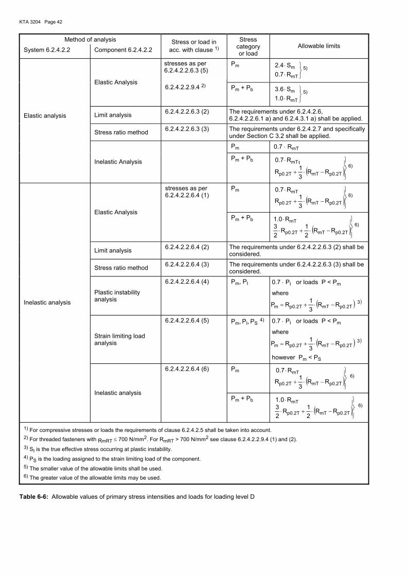
KTA 3204 Page 42
Method of analysis
System 6.2.4.2.2 Component 6.2.4.2.2 Stress or load in
acc. with clause 1)
Stress category or load
Allowable limits
stresses as per 6.2.4.2.2.6.3 (1)
Pm
⋅⋅
mT
mR7.0
S4.2 5)
Elastic Analysis 6.2.4.2.2.9.4 2) Pm + Pb
⋅⋅
mT
mR0.1
S6.3 5)
Limit analysis 6.2.4.2.2.6.3 (2) The requirements under 6.2.4.2.6, 6.2.4.2.2.6.1 a) and 6.2.4.3.1 a) shall be applied.
Stress ratio method 6.2.4.2.2.6.3 (3) The requirements under 6.2.4.2.7 and specifically under Section C 3.2 shall be applied.
Pm 0.7 ⋅ RmT
Elastic analysis
Inelastic Analysis Pm + Pb
( )
−⋅+
⋅
T2.0pmTT2.0p
tmT
RR31R
R7.06)
stresses as per 6.2.4.2.2.6.4 (1)
Pm
( )
−⋅+
⋅
T2.0pmTT2.0p
mT
RR31R
R7.06)
Elastic Analysis Pm + Pb
( )
−⋅+⋅
⋅
T2.0pmTT2.0p
mT
RR21R
23
R0.16)
Limit analysis 6.2.4.2.2.6.4 (2) The requirements under 6.2.4.2.2.6.3 (2) shall be considered.
Stress ratio method 6.2.4.2.2.6.4 (3) The requirements under 6.2.4.2.2.6.3 (3) shall be considered.
Plastic instability analysis
6.2.4.2.2.6.4 (4) Pm, PI 0.7 ⋅ PI or loads P < Pm
where
( ) )3T2.0pmTT2.0pm RR
31RP −⋅+=
Strain limiting load analysis
6.2.4.2.2.6.4 (5) Pm, PI, PS 4) 0.7 ⋅ PI or loads P < Pm
where
( ) )3T2.0pmTT2.0pm RR
31RP −⋅+=
however Pm < PS
6.2.4.2.2.6.4 (6) Pm
( )
−⋅+
⋅
T2.0pmTT2.0p
mT
RR31R
R7.0 6)
Inelastic analysis
Inelastic analysis Pm + Pb
( )
−⋅+⋅
⋅
T2.0pmTT2.0p
mT
RR21R
23
R0.1 6)
1) For compressive stresses or loads the requirements of clause 6.2.4.2.5 shall be taken into account. 2) For threaded fasteners with RmRT ≤ 700 N/mm2. For RmRT > 700 N/mm2 see clause 6.2.4.2.2.9.4 (1) and (2). 3) SI is the true effective stress occurring at plastic instability. 4) PS is the loading assigned to the strain limiting load of the component. 5) The smaller value of the allowable limits shall be used. 6) The greater value of the allowable limits may be used.
Table 6-6: Allowable values of primary stress intensities and loads for loading level D
stresses as per 6.2.4.2.2.6.3 (5)
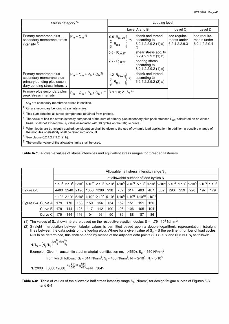
KTA 3204 Page 43
Stress category 5) Loading level
Level A and B Level C Level D
Primary membrane plus secondary membrane stress intensity 3)
Pm + Qm 1)
⋅
⋅
R32
R9.0
mT
T2.0p 7)
shank and thread according to 6.2.4.2.2.9.2 (1) a) 6)
see require-ments under 6.2.4.2.2.9.3
see require-ments under 6.2.4.2.2.9.4
0.6 ⋅ Rp0.2T shear stress acc. to 6.2.4.2.2.9.2 (1) b)
2.7 ⋅ Rp0.2T bearing stress according to 6.2.4.2.2.9.2 (1) c)
Primary membrane plus secondary membrane plus primary bending plus secon-dary bending stress intensity
Pm + Qm + Pb + Qb 2)
⋅
⋅
R98
R2.1
mT
T2.0p 7)
shank and thread according to 6.2.4.2.2.9.2 (2) a)
Primary plus secondary plus peak stress intensity
Pm + Qm + Pb + Qb + F D < 1.0; 2 ⋅ Sa 4)
1) Qm are secondary membrane stress intensities. 2) Qb are secondary bending stress intensities. 3) This sum contains all stress components obtained from preload. 4) The value of half the stress intensity composed of the sum of primary plus secondary plus peak stresses Salt, calculated on an elastic
basis, shall not exceed the Sa value associated with 10 cycles on the fatigue curve. 5) When loads are transiently applied, consideration shall be given to the use of dynamic load application. In addition, a possible change of
the modules of elasticity shall be taken into account. 6) See clause 6.2.4.2.2.9.2 (2) b). 7) The smaller value of the allowable limits shall be used.
Table 6-7: Allowable values of stress intensities and equivalent stress ranges for threaded fasteners
Allowable half stress intensity range Sa
at allowable number of load cycles N
1⋅101 2⋅101 5⋅101 1⋅102 2⋅102 5⋅102 1⋅103 2⋅103 5⋅103 1⋅104 2⋅104 5⋅104 1⋅105 2⋅105 5⋅105 1⋅106
Figure 6-3 4480 3240 2190 1650 1280 938 752 614 483 407 352 293 259 228 197 179
1⋅106 2⋅106 5⋅106 1⋅107 2⋅107 5⋅107 1⋅108 1⋅109 1⋅1010 1⋅1011
Figure 6-4 Curve A 179 170 163 159 156 154 152 151 151 150
Curve B 179 144 125 117 112 109 108 106 105 104
Curve C 179 144 116 104 96 90 89 88 87 86
(1) The values of Sa shown here are based on the respective elastic modulus E = 1.79 ⋅ 105 N/mm2. (2) Straight interpolation between tabular values is permitted based upon a double-logarithmic representation: (straight
lines between the data points on the log-log plot). Where for a given value of Sa = S the pertinent number of load cycles N is to be determined, this shall be done by means of the adjacent data points Sj < S < Si and Nj > N > Ni as follows:
( ) j
iiSSlog/
SSlog
iji N/NN/N =
Example: Given: austenitic steel (material identification no. 1.4550), Sa = 550 N/mm2
from which follows: Si = 614 N/mm2, Sj = 483 N/mm2, Ni = 2⋅103, Nj = 5⋅103
( ) 3045N2000/50002000/N 483614log/
550614log
=→=
Table 6-8: Table of values of the allowable half stress intensity range Sa [N/mm2] for design fatigue curves of Figures 6-3 and 6-4
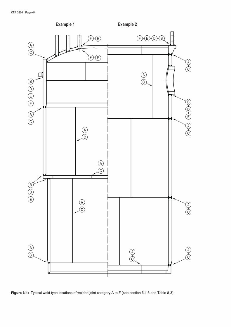
KTA 3204 Page 44
Example 1 Example 2
Figure 6-1: Typical weld type locations of welded joint category A to F (see section 6.1.6 and Table 8-3)
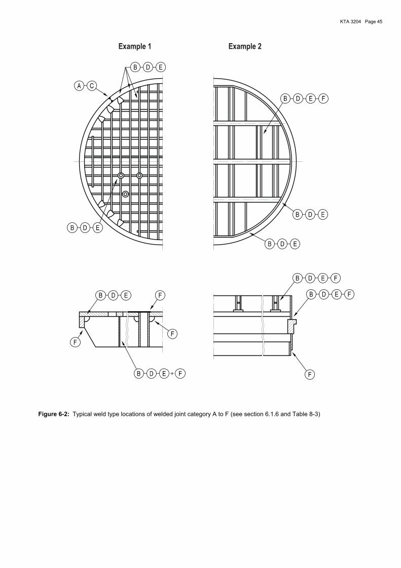
KTA 3204 Page 45
Example 1 Example 2
Figure 6-2: Typical weld type locations of welded joint category A to F (see section 6.1.6 and Table 8-3)
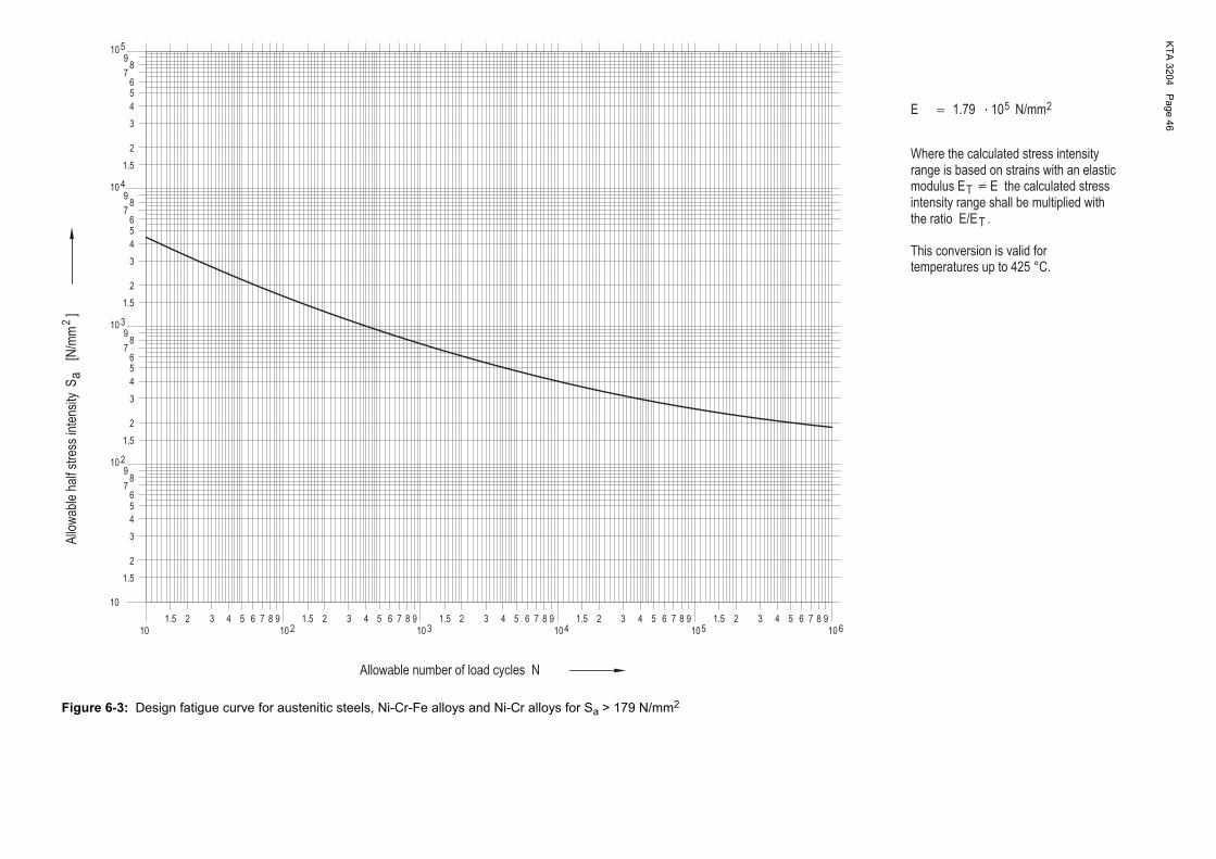
KTA
3204 Page 46
�
2
3
3
2
4
89
7
56
109
3
10 2
5
4
6
87
10
1.5 1.51.5
2
1.5
1.5
1.5
1.5
1.5
1.5
98
10
4
5
4
3
5
76
9
324
4 765 654 710
9885 6 7410
2 3310
92
8 910
3 5 63 4 710 6
8 9
65
87
4
10
2
3
2
2 98105
2 43 5 76
25
2
T
T
10
Allo
wab
leha
lfst
ress
inte
nsity
N/mm
Where the calculated stress intensityrange is based on strains with an elastic
Allowable number of load cycles N
a[N
/mm
]
1.79
S
E
modulus Eintensity range shall be multiplied with
E the calculated stress
the ratio E/E .
This conversion is valid fortemperatures up to 425 °C.
Figure 6-3: Design fatigue curve for austenitic steels, Ni-Cr-Fe alloys and Ni-Cr alloys for Sa > 179 N/mm2
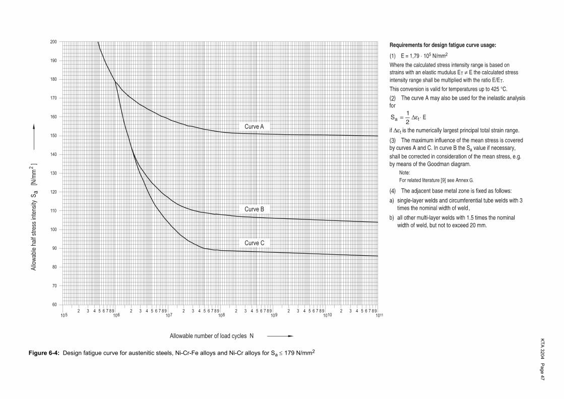
KTA
3204 Page 47
Allowable number of load cycles N
2A
llow
able
half
stre
ssin
tens
itya
[N/m
m]
S
11764 59
76108 9
104 5 6
92 3 7
82 3 8 9
10
100
90
80
130
120
110
432
70
60
5510
200
876
160
150
140
190
180
170
102 2 3543 4 8 9
105 6 76654 9873 9872
1010
Curve A
Curve B
Curve C
2
3
G
4
Figure 6-4: Design fatigue curve for austenitic steels, Ni-Cr-Fe alloys and Ni-Cr alloys for Sa ≤ 179 N/mm2
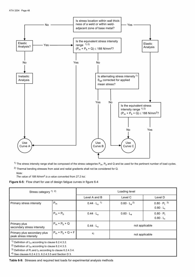
KTA 3204 Page 48
Is stress location within wall thick- No ness of a weld or within weld- Yes adjacent zone of base metal?
Is the equivalent stress intensity Yes range 1) 2) (Pm + Pb + Q) ≤ 188 N/mm2?
No Yes No Inelastic Is alternating stress intensity
1) Analysis Salt corrected for applied mean stress?
Yes No Is the equivalent stress intensity range 1) 2) (Pm + Pb + Q) ≤ 188 N/mm2?
No Yes
Use Use Use Curve A Curve B Curve C
1) The stress intensity range shall be composed of the stress categories Pm, Pb and Q and be used for the pertinent number of load cycles. 2) Thermal bending stresses from axial and radial gradients shall not be considered for Q. Note: The value of 188 N/mm2 is a value converted from 27.2 ksi.
Figure 6-5: Flow chart for use of design fatigue curves in figure 6-4
Stress category 1) 2) Loading level
Level A and B Level C Level D
Primary stress intensity Pm 0.44 ⋅ Lu 1) 0.60 ⋅ Le 2) 0.80 ⋅ Pt
3)
0.80 ⋅ Lt
Pm + Pb 0.44 ⋅ Lu 0.60 ⋅ Le 0.80 ⋅ Pt
0.80 ⋅ Lt
Primary plus secondary stress intensity
Pm + Pb + Q 0.44 ⋅ Lu not applicable
Primary plus secondary plus peak stress intensity
Pm + Pb + Q + F 4) not applicable
1) Definition of Lu according to clause 6.2.4.3.2. 2) Definition of Le according to clause 6.2.4.3.3. 3) Definition of Pt and Lt according to clause 6.2.4.3.4. 4) See clauses 6.2.4.2.3, 6.2.4.3.5 and Section D 3.
Table 6-9: Stresses and required test loads for experimental analysis methods
Elastic Analysis?
Elastic Analysis
KTA 3204 Page 49
7 Materials and material testing
7.1 Scope
This section specifies requirements for materials including weld filler metals, brazing alloy and flux for thermal spraying.
7.2 Requirements for supplies
7.2.1 Requirements to be met by the manufacturer of qual-ity class AS-RE 1 and AS-RE 2 product forms as well as for parts of quality class AS-RE 3 inside the RPV
Note: The term �manufacturer� in this Section refers to the manufacturer of material as well as to the manufacturer of weld filler metals, brazing solder and flux for thermal spraying.
(1) The manufacturer shall have manufacturing equipment and personnel at his disposal which permits a proper and state-of-the-art manufacturing of the materials.
(2) Where forming operations, heat treatments and the like are sub-contracted by other organisations, the requirements for such operations shall apply with respect to the scope of manufacturing.
(3) The manufacturers shall have test equipment at their disposal which permits the testing of materials in accordance with the corresponding DIN Standards or with other standards that apply. Test equipment from other organisations may also be employed if the requirements of this Section are met. Upon request, the test certificates of test equipment used for accep-tance tests shall be submitted to the authorized inspector.
(4) The manufacturers shall have an organisationally inde-pendent quality department to ensure the required quality during fabrication.
(5) The quality surveillance department of the manufacturer shall ensure, and document correspondingly, that the materi-als and product forms are properly manufactured.
(6) The manufacturer shall only establish acceptance test certificates if a manufacturer�s authorized inspection repre-sentative is employed by him who satisfies the requirements of DIN EN 10204 (2005-01).
(7) The name and stamp of the manufacturer�s authorized inspection representative shall be known to the authorized inspector. This also applies to the test supervisory personnel for the non-destructive examinations
(8) The manufacturer shall prove that he has performed a material appraisal relating to the manufacturing process, product form, wall thickness and heat treatment, for austenitic steels e.g. in accordance with AD 2000-Merkblatt W 2.
(9) Prior to the beginning of manufacture it shall be proved to the inspector, that the aforementioned requirements have been satisfied. The authorized inspector shall certify that all requirements have been met.
(10) All changes of the condition recorded in the first certifi-cate shall be reported to the authorized inspector responsible for the manufacturer�s works. In the case of essential changes the manufacturer shall apply for a new certificate which will be established by the authorized inspector upon fulfilment of the requirements.
(11) In individual cases delivery of product forms by the manufacturer is permitted upon agreement with the author-ized inspector even if individual items of the aforementioned requirements have not been fulfilled. In this case the quality characteristics shall be tested on the delivery by representa-tive tests and examinations.
7.2.2 Selection of materials
7.2.2.1 General requirements
The materials shall be selected by the plant vendor according to their intended application by taking into account the me-chanical, thermal and chemical loadings and the alteration possible due to neutron irradiation as well as exposure to radiation during operation, e.g. during maintenance.
7.2.2.2 Base metal
(1) Materials with characteristics in accordance with those specified in Annexes W 1 to W 3, W 5 and W 6 shall be consid-ered to be applicable because the materials have been com-pletely tested and inspected and proved to be reliable in service.
(2) Special materials of quality classes AS-RE 1 and AS-RE 2 require an initial material test certificate by the authorized inspector. The authorized inspector shall verify that a continu-ous material quality is ensured by the individual manufacturer. The tests by the authorized inspector required for special materials shall be specified with regard to type and extent such that they form, together with the supplied manufacturer�s documentation, a sufficient basis for the material certification. The proof that the required material characteristics are con-tinuously obtained shall be supported by a mathematical and statistical evaluation of already available test results. If the material is manufactured in more than one works, this shall be considered in the initial certification.
(3) If a material is to be used beyond the scope of its certi-fied applicability, additional test - if required - shall be agreed with the authorized inspector.
(4) For the components of quality class AS-RE 3 materials in addition to those mentioned in Annexes W 1 to W 3 and W 5 and W 6 are permitted if they are suited for the intended application.
7.2.2.3 Weld filler metals, brazing alloy and flux for thermal spraying
(1) The weld filler metals shall be tested for their suitability. This does not apply to filler metals for hard surfacing applica-tions.
(2) The weld filler metals, brazing alloy and flux for thermal spraying with the material characteristics laid down in Annex W 4 are deemed to be permitted due to the fact that they have been thoroughly tested and have proved to be reliable in service.
(3) Where a weld filler metal is to be used beyond the scope of its qualified application, additional tests, if any, shall be agreed upon with the authorized inspector, e.g. within a pro-cedure qualification test.
7.3 Test of material quality 7.3.1 General requirements
(1) The quality characteristics of the materials shall be as-certained by testing for which the stipulations of the Annexes W 1 to W 6 shall apply. Where tensile tests at elevated tem-peratures are required, the test temperature shall be 350 °C unless agreed otherwise.
(2) The required material tests shall be recorded in material test certificates to DIN EN 10204 (2005-01) and shall contain the following information: a) material, b) extent and dimensions of the delivery, c) identification marking, d) delivery specifications, e) test results.
KTA 3204 Page 50
Material test certificates 3.2 shall be confirmed or be estab-lished by the authorized inspector to § 20 of the Atomic En-ergy Act or by the technical inspecting agency tasked by him.
(3) Instead of material test certificate 3.1 to DIN EN 10204 (2005-01) material test certificate 3.1.B to DIN EN 10204 (1995-08) will be recognised.
(4) Instead of material test certificate 3.2 to DIN EN 10204 (2005-01) material test certificate 3.1.C to DIN EN 10204 (1995-08) will be recognised.
(5) The materials shall be tested at the manufacturer�s works.
7.3.2 Identification marking of test specimens with regard to the product forms
The test specimens with regard to the product forms shall be identified as follows:
a) Identification with regard to forming direction: aa) Longitudinal test specimen (L): Major axis of specimen is parallel to the principal
forming direction; the notch of impact test specimens shall be perpendicular to the plane of length/width di-rection.
ab) Transverse test specimen (Q): Major axis of specimen is perpendicular to the princi-
pal forming direction; the notch of impact specimen tests shall be perpendicular to the plane of length/width direction.
ac) Perpendicular test specimen (S): Major axis of specimen is perpendicular to the plane
of length/width direction; the notch of impact specimen tests shall be parallel to the principal forming direc-tion.
b) Identification with regard to the major direction of the product form shape: ba) Axial test specimen (A): Major axis of specimen is parallel to the axis of rota-
tional symmetry of the product form; the notch of im-pact tests shall be perpendicular to the cylindrical sur-face.
bb) Tangential test specimen (T): Major direction of specimen is in the direction of the
circumference; the notch of impact tests shall be per-pendicular to the cylindrical surface.
bc) Radial test specimen (R): Major axis of specimen is normal to the cylindrical sur-
face, the notch of impact tests shall be parallel to the principal direction in which the material is formed.
7.3.3 Test coupons, identification marking of test speci-mens and specimen-taking
7.3.3.1 Base metal
(1) Test coupons A sufficient amount of material shall be provided for obtaining test specimens such that, in addition to the demonstration of the mechanical properties, a sufficient amount of material remains for re-examination specimens.
(2) Identification marking of test specimens and test coupons
For the acceptance test, the test coupons shall be legibly and unambiguously marked by the authorized inspector charged
with the acceptance test prior to taking them from the product form, the test specimens prior to taking them from the test coupon. The marking of the test specimens shall make it possible to exactly determine their original location in the product form.
7.3.3.2 Weld metal
The all-weld metal shall be tested on the test coupons given in Table 7-1 which shall be welded in accordance with DIN EN ISO 15792-1 und DIN EN ISO 6847.
7.3.3.3 Brazing alloy and fluxes
The brazing alloys and fluxes shall be tested on the delivery and not on specifically manufactured specimens.
7.3.4 Heat treatment condition of the test specimens
The specimens shall be delivered with the same heat treat-ment condition as the finished products. A deviating heat treatment condition (e.g. simulation of stress relieving) will be specified in the material annexes for the respective test.
7.3.5 Tests
7.3.5.1 Chemical analysis
(1) The choice of a suitable analysis method is left to the manufacturer.
(2) In case of doubt the chemical composition shall be determined by the test procedure developed by the Chemical Committee of the Association of German Steel Manufacturers [1].
7.3.5.2 Check for resistance to hot cracking (1) To ensure resistance to hot cracking the delta ferrite content shall be determined in accordance with Sec. 7.3.5.3 with respect to the requirements in the applicable Annexes for those product forms which, in the course of further fabrication, will be subjected to welding.
(2) For the check of the molten weld metal for susceptibility to hot cracking test welds shall be made in accordance with Table 7-2 (base plate material no.: 1.4550 to DIN EN 10088-2). The examination and assessment for hot cracking shall be made by surface examination by means of the liquid pene-trant method to clause 7.3.5.6.
7.3.5.3 Determining the delta-ferrite content (1) Metallographic analysis of delta-ferrite content a) The metallographic analysis of delta-ferrite content shall
be performed in the base metal of bead-on-plate test specimens. Therefore a test specimen of the following size shall be taken from the product form:
length 200 mm, thickness ≥ 25 mm, width ≥ 40 mm, un-less the product form shows smaller dimensions.
b) A melt run with a length of at least 180 mm shall be de-posited on the test specimen with a TIG burner without weld filler metals, using the following weld parameters:
current: 160 A, feed rate: about 20 cm/min.
c) In the case of product forms where the required size of test specimens and the required weld parameters cannot be adhered to, the specimen shape and heat input shall be largely adjusted to the welding to be performed later on the product. The specimen shape and the weld parame-ters shall be contained in the test certificates.
KTA 3204 Page 51
d) The delta-ferrite content in the austenitic weld metal shall be determined on specimens of the molten all-weld metal which are taken within the acceptance testing of the weld filler metals.
e) For metallographic analysis a specimen section shall be removed from the middle of the melt run perpendicular to the surface and to the weld run axis or, in the case of all-weld-metal test coupon, perpendicular to the direction of welding progress and be prepared for metallographic exa-mination.
f) To determine the delta-ferrite content the test specimen shall be ground and polished in the usual way and etched in accordance with Murakami [2]; the metallographic struc-ture of a representative location shall be documented by micrographs (1000:1 magnification).
Note: For the determination of the delta-ferrite content generally the delta-ferrite standards of the �Reference-Atlas for a comparative evaluation of ferrite percentage in the fused zone of austenitic steel welded joints� of the International Institute of Welding [3] are used.
g) The determination of delta-ferrite content shall be docu-mented. This documentation shall contain at least the fol-lowing information: ga) result of analysis, gb) shape and dimension of test specimen, gc) weld parameters, gd) location of microsection, ge) metallographic preparation and examination, gf) photomicrographs.
(2) Mathematical estimation of delta-ferrite content a) Mathematical estimation of delta-ferrite content shall be
carried out according to De Long [4]. b) The documentation shall contain at least the following
information: ba) Cr equivalent, bb) Ni equivalent, bc) delta-ferrite content.
(3) Magnetic determination of the delta ferrite content a) The magnetic determination of the delta ferrite content in
austenitic steels and welds shall be made by delta ferrite measuring instruments.
b) Prior to the beginning of measurement the delta ferrite measuring instrument shall be calibrated by means of secondary standards to DIN EN ISO 8249, and the electri-cal and mechanical instrument zeros shall be adjusted.
c) The delta ferrite content shall be measured at representa-tive locations (e.g. in the middle of a melt run deposited in accordance with 7.3.5.3 (1) b) or in the middle of the weld run on the component.
d) The locations of measurement shall show a bright metal surface (e.g. obtained by grinding in longitudinal direction). In the case of cast materials the cast surface shall be re-moved.
e) The individual measuring values shall be recorded with indication of the location of measurement.
7.3.5.4 Crystalline structure and determination of grain size
(1) The crystalline structure of formed products shall be evaluated by means of microsections with the plane parallel to the direction of fibres or main forming and perpendicular to the surface at a magnification of 100:1. In the case of castings microsections with the plane perpendicular to the surface shall be evaluated.
(2) For this purpose, the halves of tested notch bar impact test specimens shall be used.
(3) The grain size shall be determined by means of stan-dards on microsections for the evaluation of the structure in accordance with EURONORM 103-71.
7.3.5.5 Test for resistance to intergranular corrosion (IK)
(1) Base metal and all-weld material a) The resistance to intergranular corrosion shall be demon-
strated in accordance with DIN 50914 b) The evaluation shall be made by means of the bend test
specimens described in DIN 50914. The weld metal specimen shall be taken in the direction of welding from the cover pass.
c) Deviating from DIN 50914 the weld filler metal test shall be performed on the all-weld metal specimen.
d) Where bend test specimens do not permit an unambigu-ous evaluation, a metallographic examination may be made with the aim of determining the cause of the crack (e.g. cause of crack: flaw instead of intergranular corrosion).
e) A metallographic evaluation alone is permitted if the di-mension of the product form or the weld metal do not allow for a proper bend test specimen-taking.
f) Sensitization shall be made prior to the test at the given temperature and holding time if fa) welding is performed on the product form: 650 °C ± 10 K; 0.5 h fb) stress relieving or welding and stress relieving is per-
formed on the product form:
h16/K0K10
C580−
+°
fc) weld metal in stress-relieved condition is used: 550 °C ± 10 K; 16 h The stress relieved condition covers the unannealed
condition.
g) Weld filler metals for lock welds need not be subjected to advance sensitization.
(2) Precision casting The specimens shall show the following heat treatment condi-tion: a) where used without stress relieving (only production weld-
ing or joint welding) production control test with all heat treatments actually performed and subsequent sensitiza-tion:
550 °C ± 10 K; 16 h
b) where used in the stress-relieved condition: sensitization:
h8/K0K10
C580−
+°
The test surface of the specimens tested for resistance to intergranular corrosion shall show the same surface condition as the components.
7.3.5.6 Non-destructive examinations
7.3.5.6.1 General requirements
(1) The following requirements for performing non-destructive examinations on product forms and parts during manufacture apply unless deviating requirements are speci-fied in the materials test sheets.
(2) Prior to the beginning of the examinations, specifically the type of examinations, the examination requirements and
KTA 3204 Page 52
the techniques to be used shall be laid down in detail and described in examination instructions by the manufacturer�s test supervisory personnel.
(3) For surface examinations instructions established by the manufacturer and being independent of the project and test object may be used in lieu of test instructions.
(4) The test instructions shall contain detailed information on: a) Assignment to the individual test objects, b) time of testing as far as it influences the extent and per-
formance of the test in accordance with the test and in-spection sequence plan,
c) test requirements, test methods and test facilities/equip-ment to be used, type of sensitivity adjustment for ultra-sonic testing,
d) if required, additional explanations regarding the perform-ance of the test (e.g. drawing to scale),
e) intended substitute measures to be taken if the applicabil-ity of the requirements of this Section is restricted,
f) reference system and counting direction for a description of indications or irregularities assigned to a test object,
g) if required, supplementary information for recording and evaluating indications or irregularities (e.g. in the case of technical substitute measures).
(5) A marking identifying the points of origin and major di-rections of the applied coordinate systems shall be made on the test object and be preserved until the test results have been evaluated.
(6) In the case of random checks or examination of test lots on product forms with indications that are not permissible, the extent of examination shall be doubled by applying the same criteria. Where further indications are found in these examina-tions that are not permissible, the extent of examination shall be increased to 100 %.
7.3.5.6.2 Requirements for personnel performing non-destructive examinations
(1) Test supervisors shall a) have the technical knowledge required to perform their
tasks and know the possibilities of application as well as limits of test procedures,
b) have basic knowledge of fabrication processes and of the characteristic appearance of fabrication discontinuities.
The test supervisory personnel shall normally be independent from the fabrication department and the authorized inspector shall be notified of their names. The test supervisory person-nel is responsible for the application of the test procedure and for the details of the implementation of the test in accordance with the relevant specifications. They are responsible for the employment of qualified and certified operators. This applies also to the employment of personnel not belonging to the works. The test supervisory personnel shall sign the test re-port.
(2) The test supervisory personnel shall have been qualified and certified for the examination procedures in the relevant product or industrial sectors at least with level 2 to DIN EN 473. In the case of welded joints between RPV inter-nals and butterings or claddings on the RPV as well as be-tween RPV internals and welded-on load attachment points, level 3 qualification and certification is required for radio-graphic and ultrasonic examinations.
(3) The NDT operators shall be capable of conducting the tests described in clause 7.3.5.6 and in Section 8.9 as well as in the material annexes. They shall have been qualified and certified to DIN EN 473 for the applicable examination proce-dure in the relevant product or industrial sectors. For radio-
graphic and ultrasonic examinations at least level 2 qualifica-tion and certification is required.
(4) The test supervisory personnel and the NDT operators shall have sufficient visual capacity which is to be checked by an ophthalmologist, optician or another medical person in conjunction with DIN EN 473. The visual capacity shall be checked yearly.
7.3.5.6.3 Surface examination by means of the liquid pene-trant method
7.3.5.6.3.1 General requirements
(1) The test surfaces shall be free from impurities. Disconti-nuities affecting the test results shall be removed. The arith-metical mean deviation of the assessed profile (average roughness) Ra shall not exceed the following values depend-ing on the process of surface treatment: a) unmachined surfaces Ra < 20 µm b) machined surfaces Ra < 10 µm The examination shall be performed by determination of the arithmetical mean deviation of the assessed profile (average roughness) Ra to DIN EN ISO 4287 by means of electrical stylus-type instruments or by visual examination for compari-son with respective standards.
(2) Liquid penetrants shall preferably be used. Fluorescent penetrants or fluorescent dye penetrants may be used. Where testing for susceptibility to hot cracking in accordance with clause 7.3.5.2 (2) is performed, fluorescent penetrants shall be used.
(3) Solvents or water or both in combination may be used as penetrant remover.
(4) Only wet developers suspended in an aqueous solvent shall be used. Dry developers may only be applied on the scanning surface by electrostatic charging.
(5) For the examination system at least sensitivity class 3 to DIN EN ISO 3452-2 Section 4.2.2 or sensitivity class 2 to DIN EN ISO 3452-2 Section 4.2.3 shall be adhered to. Where testing for susceptibility to hot cracking in accordance with clause 7.3.5.2 (2) is performed, sensitivity class 4 to DIN EN ISO 3452-2, clause 4.2.2 shall be satisfied.
(6) The suitability of the examination system (penetrant, solvent remover and developer) shall be demonstrated by means of a sample examination as to DIN EN ISO 3452-2. Verification shall be submitted to the authorized inspector.
(7) Liquid penetrants in test equipment and partly used open tanks (except for aerosol cans) shall be monitored by the user with flux indicator 2 to DIN EN ISO 3452-3. In this test the maximum penetration and development times shall not exceed the minimum times specified for the evaluation. The examination sensitivity obtained shall be recorded.
7.3.5.6.3.2 Performance of the examination
(1) Liquid penetrant inspections shall be performed to DIN EN 571-1. Where testing for susceptibility to hot cracking in accordance with clause 7.3.5.2 (2) is performed, the entire weld and heat-affected zone of the austenitic base metal shall be examined.
(2) The penetration time shall be at least half an hour.
(3) As soon as possible after drying of the developer a first evaluation shall be made. A further evaluation shall not be made before half an hour after the first evaluation has passed. Where testing for susceptibility to hot cracking in accordance with clause 7.3.5.2 (2) is performed, the following evaluation times apply: directly upon drying of the developer, after 15 minutes, 30 minutes and 60 minutes.
KTA 3204 Page 53
(4) Further evaluation times are required if during the sec-ond evaluation crack-like indications are detected which were not visible during the first evaluation.
Note: Further evaluation times are required if during the second evalua-tion crack-like indications are detected which were not visible dur-ing the first evaluation.
(5) The evaluation shall be made in consideration of the results of all evaluations.
7.3.5.6.3.3 Acceptance standards
(1) Forged and rolled product forms The requirements under Table 7-4 apply. The frequency of acceptable indications shall locally not be higher than 10 per square decimetre and, with respect to the entire surface area, not higher than 5 per square decimetre.
(2) Welded pipes The requirements under Table 8-8 apply.
(3) Castings The following applies: a) Indications, the largest dimension of which is smaller or
equal to 1.5 mm, shall not be included in the evaluation. b) No linear indication and indications that might indicate the
existence of cracks are allowed. c) Round indications with a diameter exceeding 3 mm are
not allowed. d) More than 10 allowable indications with an extension ex-
ceeding 1.5 mm and equal to or smaller than 3 mm are not permitted:
for each 100 cm2 or for the entire surface area of compo-nents with surfaces less than 100 cm2.
(4) Testing for hot cracks Linear indications and regularly occurring indications shall be documented by means of photographs with 200 times magni-fication and be examined by microsections. Hot cracks are not permitted, individual irregular dendrite separations are permit-ted.
7.3.5.6.4 Ultrasonic examinations
(1) Condition of examination surfaces a) The examination surfaces shall be free from discontinui-
ties and impurities affecting the test result. b) Where an opposite face is used as reflecting surface it
shall meet the same requirements as the examination sur-face.
c) The arithmetical mean deviation of the assessed profile (average roughness) Ra of the examination and reflecting surfaces should not exceed the value 20 µm. The exami-nation shall be performed by determination of the arith-metical mean deviation of the assessed profile (average roughness) Ra to DIN EN ISO 4287 by means of electrical stylus-type instruments or by visual examination for com-parison with respective standards.
d) The examination surfaces� waviness shall be so little that the distance between probe shoe surface and test surface does not exceed 0.5 mm at any point, not taking into ac-count the radius of surface curvature.
(2) Requirements regarding test equipment and search units a) Test equipment The test equipment and accessories used including the
required auxiliary means shall show sufficient accuracy and stability for the intended use.
Test instruments and probes shall basically be used which meet the requirements of DIN EN 12668-1 or DIN EN 12668-2. Deviating from this requirement test instruments and probes may be used which were fabricated prior to the coming into effect of the aforementioned standards, if they meet the requirements of DIN 25450. The measuring and testing equipment to be used shall be monitored. The type and intervals of monitoring shall be fixed by the equipment manufacturer with a view to the accuracy of the equipment. The testing of such measuring and testing equipment shall be certified. DIN EN 12668-3 shall be used for checking the properties of the entire test equip-ment.
It shall be possible to determine all possible echo signal height ratios used in the equipment sensitivity range with an accuracy of ± 1 dB, viz. with the aid of a dB calibrated attenuator and a suitable scale division on the screen.
The scanning areas that can be chosen on the equipment shall overlap. Within each individual scanning area the time-base sweep shall be continuously adjustable and be linear with an accuracy better than 5 % of the scanning area.
The combination of equipment, cables and search units of various manufacturers is permitted if it is ensured (e.g. by measurements on reference reflectors) that the exactness of results is not affected.
b) Search units Probes shall basically be used which meet the require-
ments of DIN EN 12668-2. Deviating from this requirement probes may be used which were fabricated prior to the coming into effect of the aforementioned standard, if they meet the requirements of DIN 25450.
Search units with common or separate transmitter and receiver probes may be used.
The test frequency shall be between 2 and 4 MHz. In the case of examinations of materials with large sound at-tenuations test frequencies of smaller than 2 MHz are permitted if it can be proved that the required recording level is satisfied.
In the case of curved examination surfaces the search unit (probe) shall be located with the probe index on the centre of the surface. At no point shall the probe shoes have a distance greater than 0.5 to the examination surface. Where the distance is greater, the probe shall be ground. This is the case if L2 exceeds 2 x d.
where L : search unit dimension in direction of curvature d : curvature diameter of test object
(3) Preparation and performance of the test a) Range calibration and adjustment of sensitivity levels The range calibration and sensitivity adjustment shall be
made on the test object or on a similar reference block. All echo indications to be recorded shall reach at least 1/5 of the screen scale height at the largest possible sound path.
For the calibration and examination the same couplant shall be used. Only such couplants shall be used which do not damage the object (e.g. corrosion). Upon examination, all couplant residues shall be removed from the test ob-ject.
Test object, reference block and search units shall ap-proximately have the same temperature.
When setting the sensitivity level and during the examina-tion only the gain control, but no other control element (e.g. for frequency range, pulse energy, resolution, threshold value) shall be adjusted. A threshold value may only be used in exceptional justified cases.
Prior to the examination, the sensitivity level and range adjustments shall be made after the warm-up periods given by the instrument manufacturer. Both adjustments
KTA 3204 Page 54
shall be checked at suitable intervals. Where in this check clear deviations from the check made before are found, all examinations performed after that check shall be repeated with a corrected adjustment.
b) Corrections of sensitivity level adjustment Where the sensitivity level is adjusted on reference blocks,
transfer measurements shall be made on the reference block and the test object to take account of sound attenua-tion and coupling differences in order to attain the same sensitivity levels by gain corrections, if required. When us-ing differing materials for search units and test object the difference in sound velocity shall be taken into account for range adjustment and for the angular deviation in case of angle beam scanning.
The highest sound attenuation values shall be considered for all search units and sound entry directions.
The evaluation of the reflector indication shall be made in due consideration of the actual sound attenuation values measured adjacent to the indicated echos.
c) Sound entry directions Under consideration of the product form the sound entry
directions are specified in the Material Annexes.
d) Recording levels All indications reaching or exceeding the recording levels
specified in the product-form related Material Annexes shall be recorded. The sensitivity level shall be adjusted in consideration of the transfer correction and the sound at-tenuation, if any. The DGS method as well as the refer-ence block method or the DAC method may be used. In the case of probes with adjusted contact surfaces, the DGS method shall not be used. The maximum echo signal height of a reflector is related to the applicable recording level in dB. The sound attenuation values to be considered shall be recorded. Back wall echoes equal to or greater than 18 dB shall be recorded. In the case of austenitic ma-terials and nickel alloys the recording level may, if re-quired, be increased accordingly to attain a signal-to-noise ratio of at least 6 dB, but only up to 6 dB below the accep-tance level. The recording level attained in the test shall be recorded in such a case. Where reflectors accumulate whose distance from each other is smaller than the crystal diameter and for longitudinally extended reflectors the ap-plicable recording level shall be lowered by 6 dB.
e) Size of reflectors In the case of straight-beam scanning the extension of
indications transverse to the direction of sound propaga-tion shall be measured according to the half-amplitude method in which case the sound path shall attain once the near-field length, if possible.
The accuracy of determination of the reflector extension may be increased by additional examinations (e.g. by con-sidering the sound beam spread angle or by the use of special probes).
If this leads to values measured below the threshold level the recorded length shall be indicated to the point where the echo disappears.
Recorded lengths over 10 mm shall be measured, shorter recorded length shall be recorded as �< 10 mm�.
f) Location of reflectors For all indications liable to recording the length, depth and
width shall be recorded in a proper coordinate system.
g) Time of testing The acceptance test shall be performed in the delivery
condition according to Section 7 at the most favourable point in time for testing and in the most simple geometric condition, where possible.
(4) Evaluation and acceptance levels The acceptance levels are specified in the product-form re-lated Material Annexes. In addition, the following applies: a) Reflections from regions which will definitely not be re-
moved during finish-machining shall not be considered, but recorded only. All echo indications from the structure shall not be part of the evaluation but shall be recorded in the test record.
b) Where during straight-beam scanning using the DGS method liable-to-record echo indications of reflections are found in the area of lateral wall effect influence, these in-dications shall be verified by means of straight-beam scanning using the reference reflector method or by means of purposive angle beam scanning.
Where the area of lateral wall effect is omitted due to the cutting-to size of the test object, this condition shall pref-erably be re-examined. The results of the re-examination shall be considered in the evaluation.
c) In regions with signal-to-noise ratios smaller than or equal to 6 dB, or if the back-wall echo falls down to the recording level for which no explanation is found, examinations (e.g. sound attenuation measurements) shall be made by agreement with the authorized inspector which make a decision on the usability of the component possible.
d) Where the acceptance standards are exceeded or reflec-tor indications below the recording level accumulate which cannot be resolved into single echo indications for one search unit position or in the case of search unit dis-placement, or which cannot be clearly correlated to the sound beam angles used, supplementary examinations (e.g. by scanning in different directions) shall be per-formed. Where these examinations (e.g. by loss of inten-sity of a signal compared to product areas free from indi-cations) show planar discontinuities, these locations shall not be accepted.
e) In the case of test objects with a wall thickness exceeding 15 mm, the reference reflector method with a rectangular notch of 1 mm depth as reference reflector may be used for sensitivity level adjustment for near-surface areas.
7.3.5.6.5 Radiographic examination (1) Surface condition All visible surfaces discontinuities that may adversely affect the evaluation shall be removed.
(2) Performance of examination a) The examination of welded joints shall be made to DIN EN
1435, for product forms to DIN EN 444 in correspondence with DIN EN 12681.
b) The requirements of class B to DIN EN 1435 or to DIN EN 444 shall be met. The substitute solution of Section 4 of DIN EN 1435 shall not be applied in this case. The image quality values of image quality class B to DIN EN 462-3 shall be adhered to in which case the image quality indica-tors to DIN EN 462-1 shall be used.
c) Stipulations shall be made to clearly indicate the film loca-tion and film number, referred to the reference system.
d) In the examination X-ray tubes shall be used unless an at least equivalent evaluation is possible by the use of other radiation sources. Film/screen combinations with an as high as possible resolution and preferably vacuum cas-settes shall be used.
e) The film shall be marked with such an identification as to make the traceability to the test object possible.
f) Imaging plates may be used instead of films if at least the same image quality as with the required film/screen com-binations can be obtained.
KTA 3204 Page 55
(3) Evaluation of test results The acceptance levels are specified in the product-form rela-ted Material Annexes.
7.3.5.6.6 Examination of surface condition
The examination shall be made by visual inspection. The type of treatment and surface condition shall be laid down in the order to meet the requirements of Table 7-3.
7.3.5.6.7 Visual examinations
(1) Visual examinations shall be performed as local visual examination to DIN EN ISO 13018 in the form of direct visual examination.
(2) Crack-like discontinuities are not permitted. Where dis-continuities cannot be clearly assigned, they shall be subject to a surface examination to clause 7.3.5.6.3.2. The evaluation shall be made in accordance with the pertinent material speci-fication sheet. Where no requirements are laid down in this sheet, Table 7-4 applies.
7.3.5.6.8 Check for freedom of external ferrite
(1) The surfaces shall be examined by immersion in, or continuous wetting with fully demineralized water. Wetting may be achieved by sprinkling, spraying or applying filter paper soaked in demineralized water. The contact time of the water on the examined surface shall be at least 6 hours. The fully demineralized water used for this treatment shall satisfy the following guide values: Appearance: clear, colourless and odourless Conductivity at 25 °C: ≤ 10 µS/cm Chloride: ≤ 0.5 mg/kg Sulphate: ≤ 0.5 mg/kg
Note: Where external ferrite is present on the surface, local rust-brown discolouration will appear at the location of the ferrite particles.
(2) The surfaces shall be examined by visual inspection and be evaluated as follows: a) Where indications are found on the examined surface,
examination areas of approximately 1 dm2 shall be ar-ranged around these indications. The examination surface shall be arranged such that it covers the most unfavour-able distribution of indications.
b) Ferrite contamination is only permitted if ba) at least 75 % of the surface subdivided in areas of
1 dm2 do not show any indication, bb) the extension of indication does not exceed 3 mm, bc) a maximum of 5 indications exists on an area of 1 dm2.
7.3.6 Re-examination
(1) Test results that are based on incorrect performance of the test, on incorrect preparation of the test specimens, or on a random narrow flaw location in one test specimen may be disregarded in determining the fullfillment of test require-ments, and the individual examination may be repeated (re-examination).
(2) If the test results of a properly performed examination do not meet the requirements, the further procedure is as follows:
a) In the case of individual examination for each inadequate test two additional tests shall be carried out on specimen taken from the same location. If at least one test result of the re-examinations does not meet the requirements the test unit shall be rejected.
b) In the case of lot examination the piece that does not meet the requirements may be excluded from the lot and be subjected to an individual examination. It shall be replaced by two other pieces from the lot which shall both be sub-jected to the required examinations. If at least one test re-sult of the re-examinations does not meet the require-ments the lot shall basically be rejected. In exceptional cases an individual examination may be agreed upon with the authorized inspector.
(3) If the cause for the inadequacy of an examination can be removed, e.g. by an adequate post treatment, this post treat-ment may be carried out provided, the characteristics influ-enced by this procedure are subsequently re-examined.
7.4 Identification marking of the product forms
(1) All product forms shall be marked clearly, durably, and such that an unambiguous correlation to the test certificates is possible at all times.
(2) The identification marking of the base metal shall nor-mally contain the following information: a) material identification (abbreviated name or identification
code), b) identification of the material manufacturer, c) melt number, d) test specimen number (plate mark, piece mark, ring mark,
lot number), if required, e) certification stamp of the operator for non-destructive
examinations, if applicable. f) for bolts, nuts and small parts a short symbol instead of
the data required as per a) to e), which shall ensure the traceability of the parts to the acceptance test certificate,
g) certification stamp of the authorized inspector, if required,
(3) Weld filler metals shall be identified to meet the re-quirements of DIN EN 1600, DIN EN ISO 14172, DIN EN ISO 14343, DIN EN ISO 17633 or DIN EN ISO 18274.
(4) The marking shall be effected: a) by means of low-stress steel stamps, b) by means of colour markings insoluble in water (e.g. for
plates with a thickness equal to or smaller than 6 mm, thin-walled tubes and weld filler metals),
c) by means of attachment plates (e.g. tubes with an outer diameter equal to or smaller than 18 mm, for bars with an outer diameter equal to or smaller than 25 mm, flux),
d) for threaded structural fasteners to DIN EN ISO 3506-1 and DIN EN ISO 3506-2 with the stipulations specified therein.
(5) Identification marking for small parts may be omitted if a) stamping is not possible or only difficult to apply, and b) a certificate examined by the quality department of the
manufacturer or the authorized inspector is available.
KTA 3204 Page 56
Filler metal Test coupon for chemical analysis Tensile, notch impact , IGSCC and delta ferrite content test specimens
rod electrode ∅ ≤ 2.5 mm welding rod ∅ ≤ 2.5 mm wire electrode/welding wire ∅ < 1.2 mm
form 1.1 to DIN EN ISO 15792-1
rod electrode ∅ > 2.5 mm welding rod ∅ > 2.5 mm wire electrode/welding wire 1.2 mm ≤ ∅ ≤ 2.4 mm
form 1.3 to DIN EN ISO 15792-1
wire electrode/welding wire ∅ > 2.4 mm
to DIN EN ISO 6847 weld test coupon for inert gas welding:At least 8 runs shall be welded on a base plate of similar material. Distance at least A = 8 mm or 4 layers.When test coupons to DIN EN 1597-1 are required they may be used for chemical analysis. form 1.4 to DIN EN ISO 15792-1
electrode-flux combination form 1.3 or 1.4 to DIN EN ISO 15792-1
Table 7-1: Testing of the all-weld metal according to Section 7.3.3.2
Filler metal Shape of the test coupons
Rod electrode ∅ < 2.5 mm Welding rod ∅ < 2.5 mm Wire electrode/welding wire ∅ < 1.2 mm
Double fillet weld type B, DIN EN ISO 17641-2
Rod electrode ∅ ≥ 2.5 mm Welding rod ∅ ≥ 2.5 mm Wire electrode/welding wire ∅ ≥ 1,2 mm
Ring-segment test coupon to Annex E
Electrode-flux combination Cylindrical test coupon to DIN 50129 (cylinder length ≥ 300 mm)
Table 7-2: Weld test coupons for testing welds susceptible to hot cracking according to clause 7.3.5.2 (2)
Symbol Type of treatment Surface condition Remarks
Flat products (plate, sheet and strip), bars, sections and forgings
1E Hot formed, heat treated, me-chanically descaled
Largely free from scale (however, individual black spots may be present); not without surface de-fects
The type of mechanical descaling, e.g. tube grinding or shot blasting, depends on the type of steel and product from and is left to the manufacturer unless agreed otherwise
1D Hot formed, heat treated, pickled Free from scale (locally ground if required); not without surface de-fects
Usual standard for most of the steel types to ensure proper corrosion resistance; also usual type of treatment for further process-ing. Grinding marks shall not be present. Not as smooth as 2D or 2B
1X Hot formed, heat treated, rough-machined
Free from scale (however some processing indentations may be present); not without surface de-fects
Products in the as-processed condition to be used or be processed further (hot or cold)
1G Hot formed, heat treated, des-caled, prepared or peeled off in the case of wire rod; dressed by machining
More or less uniform and bright appearance; without surface de-fects
Suited for special applications (flow forming and/or cold or hot heading). Surface rough-ness may be specified
2E Cold formed, heat treated, me-chanically descaled
Raw and blunt Usually used for steels with high resistance to scaling. Pickling may be performed sub-sequently
2D Cold formed, heat treated, pick-led
Smooth Type of treatment to ensure adequate form-ing properties, but not so smooth as 2B or 2R
2B Cold formed, heat treated, pick-led, cold dressed
Smoother than 2D Most frequent type of treatment for most of the steel types to ensure proper corrosion resistance, smoothness and evenness. Also usual type of treatment intended for further processing. Re-rolling may be effected by stretch levelling.
2D 2H, heat treated, pickled and dressed (optional)
Smooth and dull or bright; not without surface defects
Dressing allows the restoration of the me-chanical properties upon cold forming. Products with good forming properties (flow forming) and special magnetic properties
Table 7-3: Type of treatment and surface condition of product forms as per clause 7.3.5.6.6
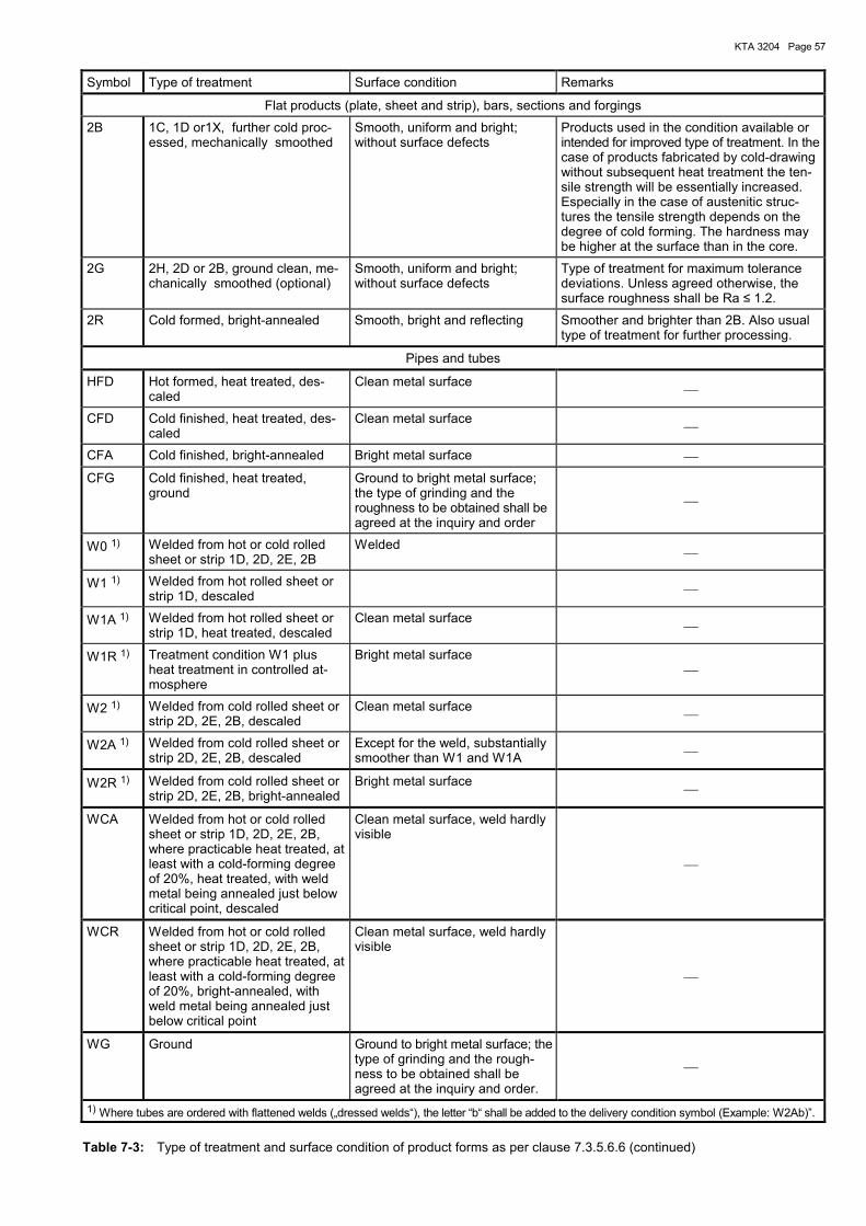
KTA 3204 Page 57
Symbol Type of treatment Surface condition Remarks
Flat products (plate, sheet and strip), bars, sections and forgings
2B 1C, 1D or1X, further cold proc-essed, mechanically smoothed
Smooth, uniform and bright; without surface defects
Products used in the condition available or intended for improved type of treatment. In the case of products fabricated by cold-drawing without subsequent heat treatment the ten-sile strength will be essentially increased. Especially in the case of austenitic struc-tures the tensile strength depends on the degree of cold forming. The hardness may be higher at the surface than in the core.
2G 2H, 2D or 2B, ground clean, me-chanically smoothed (optional)
Smooth, uniform and bright; without surface defects
Type of treatment for maximum tolerance deviations. Unless agreed otherwise, the surface roughness shall be Ra ≤ 1.2.
2R Cold formed, bright-annealed Smooth, bright and reflecting Smoother and brighter than 2B. Also usual type of treatment for further processing.
Pipes and tubes
HFD Hot formed, heat treated, des-caled
Clean metal surface
CFD Cold finished, heat treated, des-caled
Clean metal surface
CFA Cold finished, bright-annealed Bright metal surface
CFG Cold finished, heat treated, ground
Ground to bright metal surface; the type of grinding and the roughness to be obtained shall be agreed at the inquiry and order
W0 1) Welded from hot or cold rolled sheet or strip 1D, 2D, 2E, 2B
Welded
W1 1) Welded from hot rolled sheet or strip 1D, descaled
W1A 1) Welded from hot rolled sheet or strip 1D, heat treated, descaled
Clean metal surface
W1R 1) Treatment condition W1 plus heat treatment in controlled at-mosphere
Bright metal surface
W2 1) Welded from cold rolled sheet or strip 2D, 2E, 2B, descaled
Clean metal surface
W2A 1) Welded from cold rolled sheet or strip 2D, 2E, 2B, descaled
Except for the weld, substantially smoother than W1 and W1A
W2R 1) Welded from cold rolled sheet or strip 2D, 2E, 2B, bright-annealed
Bright metal surface
WCA Welded from hot or cold rolled sheet or strip 1D, 2D, 2E, 2B, where practicable heat treated, at least with a cold-forming degree of 20%, heat treated, with weld metal being annealed just below critical point, descaled
Clean metal surface, weld hardly visible
WCR Welded from hot or cold rolled sheet or strip 1D, 2D, 2E, 2B, where practicable heat treated, at least with a cold-forming degree of 20%, bright-annealed, with weld metal being annealed just below critical point
Clean metal surface, weld hardly visible
WG Ground Ground to bright metal surface; thetype of grinding and the rough-ness to be obtained shall be agreed at the inquiry and order.
1) Where tubes are ordered with flattened welds (�dressed welds�), the letter �b� shall be added to the delivery condition symbol (Example: W2Ab)�.
Table 7-3: Type of treatment and surface condition of product forms as per clause 7.3.5.6.6 (continued)
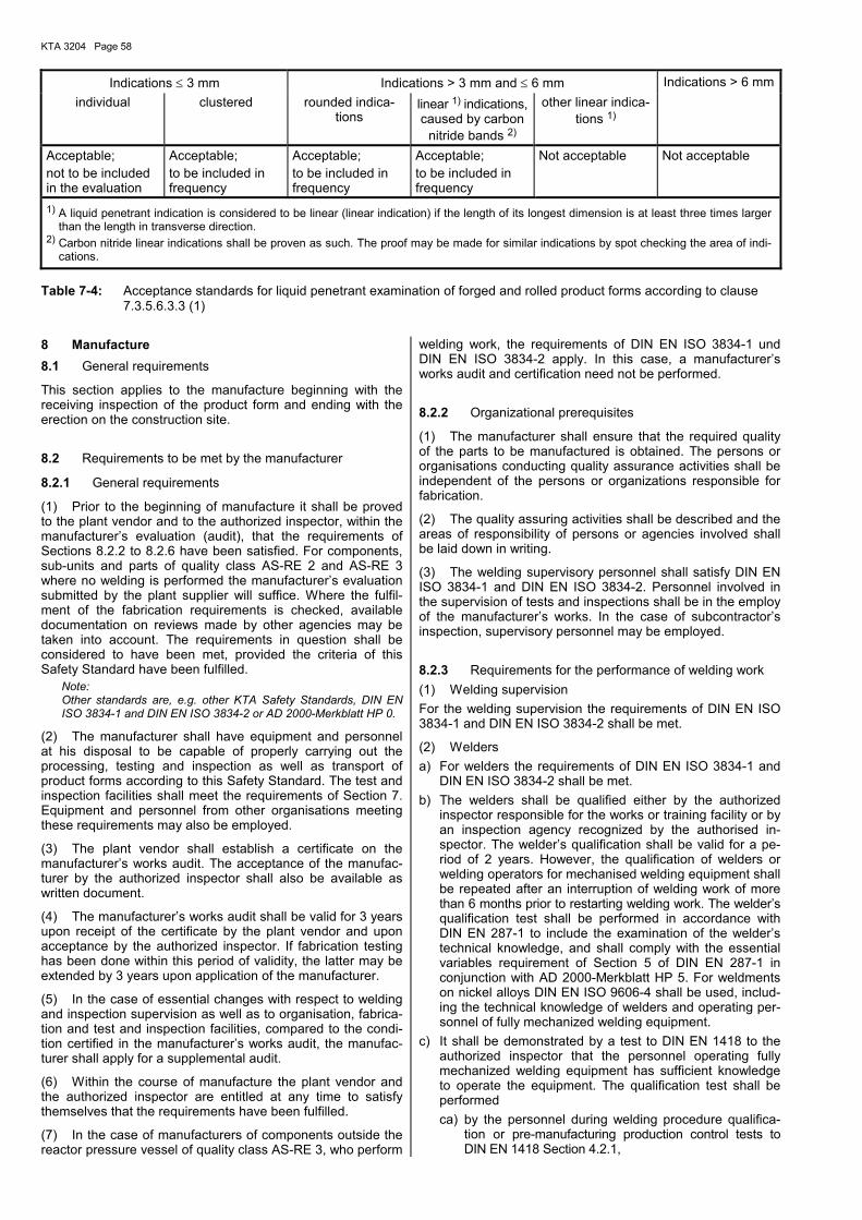
KTA 3204 Page 58
Indications ≤ 3 mm Indications > 3 mm and ≤ 6 mm Indications > 6 mmindividual clustered rounded indica-
tions linear 1) indications, caused by carbon
nitride bands 2)
other linear indica-tions 1)
Acceptable; not to be included in the evaluation
Acceptable; to be included in frequency
Acceptable; to be included in frequency
Acceptable; to be included in frequency
Not acceptable Not acceptable
1) A liquid penetrant indication is considered to be linear (linear indication) if the length of its longest dimension is at least three times larger than the length in transverse direction.
2) Carbon nitride linear indications shall be proven as such. The proof may be made for similar indications by spot checking the area of indi-cations.
Table 7-4: Acceptance standards for liquid penetrant examination of forged and rolled product forms according to clause 7.3.5.6.3.3 (1)
8 Manufacture 8.1 General requirements
This section applies to the manufacture beginning with the receiving inspection of the product form and ending with the erection on the construction site.
8.2 Requirements to be met by the manufacturer
8.2.1 General requirements
(1) Prior to the beginning of manufacture it shall be proved to the plant vendor and to the authorized inspector, within the manufacturer�s evaluation (audit), that the requirements of Sections 8.2.2 to 8.2.6 have been satisfied. For components, sub-units and parts of quality class AS-RE 2 and AS-RE 3 where no welding is performed the manufacturer�s evaluation submitted by the plant supplier will suffice. Where the fulfil-ment of the fabrication requirements is checked, available documentation on reviews made by other agencies may be taken into account. The requirements in question shall be considered to have been met, provided the criteria of this Safety Standard have been fulfilled.
Note: Other standards are, e.g. other KTA Safety Standards, DIN EN ISO 3834-1 and DIN EN ISO 3834-2 or AD 2000-Merkblatt HP 0.
(2) The manufacturer shall have equipment and personnel at his disposal to be capable of properly carrying out the processing, testing and inspection as well as transport of product forms according to this Safety Standard. The test and inspection facilities shall meet the requirements of Section 7. Equipment and personnel from other organisations meeting these requirements may also be employed.
(3) The plant vendor shall establish a certificate on the manufacturer�s works audit. The acceptance of the manufac-turer by the authorized inspector shall also be available as written document.
(4) The manufacturer�s works audit shall be valid for 3 years upon receipt of the certificate by the plant vendor and upon acceptance by the authorized inspector. If fabrication testing has been done within this period of validity, the latter may be extended by 3 years upon application of the manufacturer.
(5) In the case of essential changes with respect to welding and inspection supervision as well as to organisation, fabrica-tion and test and inspection facilities, compared to the condi-tion certified in the manufacturer�s works audit, the manufac-turer shall apply for a supplemental audit.
(6) Within the course of manufacture the plant vendor and the authorized inspector are entitled at any time to satisfy themselves that the requirements have been fulfilled.
(7) In the case of manufacturers of components outside the reactor pressure vessel of quality class AS-RE 3, who perform
welding work, the requirements of DIN EN ISO 3834-1 und DIN EN ISO 3834-2 apply. In this case, a manufacturer�s works audit and certification need not be performed.
8.2.2 Organizational prerequisites
(1) The manufacturer shall ensure that the required quality of the parts to be manufactured is obtained. The persons or organisations conducting quality assurance activities shall be independent of the persons or organizations responsible for fabrication.
(2) The quality assuring activities shall be described and the areas of responsibility of persons or agencies involved shall be laid down in writing.
(3) The welding supervisory personnel shall satisfy DIN EN ISO 3834-1 and DIN EN ISO 3834-2. Personnel involved in the supervision of tests and inspections shall be in the employ of the manufacturer�s works. In the case of subcontractor�s inspection, supervisory personnel may be employed.
8.2.3 Requirements for the performance of welding work (1) Welding supervision For the welding supervision the requirements of DIN EN ISO 3834-1 and DIN EN ISO 3834-2 shall be met.
(2) Welders a) For welders the requirements of DIN EN ISO 3834-1 and
DIN EN ISO 3834-2 shall be met. b) The welders shall be qualified either by the authorized
inspector responsible for the works or training facility or by an inspection agency recognized by the authorised in-spector. The welder�s qualification shall be valid for a pe-riod of 2 years. However, the qualification of welders or welding operators for mechanised welding equipment shall be repeated after an interruption of welding work of more than 6 months prior to restarting welding work. The welder�s qualification test shall be performed in accordance with DIN EN 287-1 to include the examination of the welder�s technical knowledge, and shall comply with the essential variables requirement of Section 5 of DIN EN 287-1 in conjunction with AD 2000-Merkblatt HP 5. For weldments on nickel alloys DIN EN ISO 9606-4 shall be used, includ-ing the technical knowledge of welders and operating per-sonnel of fully mechanized welding equipment.
c) It shall be demonstrated by a test to DIN EN 1418 to the authorized inspector that the personnel operating fully mechanized welding equipment has sufficient knowledge to operate the equipment. The qualification test shall be performed ca) by the personnel during welding procedure qualifica-
tion or pre-manufacturing production control tests to DIN EN 1418 Section 4.2.1,
KTA 3204 Page 59
or cb) as test prior to the beginning of fabrication in accor-
dance with clause 4.2.2 of DIN EN 1418. For test as per cb), the extent of testing laid down in DIN
EN 287-1, Section 6.4 and the evaluation criteria of DIN EN 287-1, Section 7 apply to steel, and the extent of test-ing laid down in DIN EN ISO 9604-4, Section 7.4 and evaluation criteria of DIN EN ISO 9604-4, Section 8 apply to nickel alloys.
(3) The proof of technical knowledge shall be rendered by the examination to DIN EN 1418, Annex A.
(4) Welding equipment When using welding equipment instruments for monitoring the welding parameters shall be available.
8.2.4 Requirements for the performance of brazing work
For the performance of high-temperature brazing heating equipment is required which is capable of creating a high vacuum so that brazing is possible with little discolouration. The heating equipment shall be provided with measuring instruments that record temperature and vacuum versus time.
8.2.5 Requirements for the performance of heat treatments
(1) The heat treatment facilities shall make possible a su-fliciently accurate and uniform temperature control on the work piece for the heat treatment selected. To this end, tem-perature-versus-time recording instruments shall be available to show a measuring accuracy of ± 10 K.
(2) Stationary heat treatment facilities which are used for components not provided with thermocouples, shall have been tested within the last six months. In this case, the accu-racy of indication of the measuring instruments shall be checked at intervals of not more than 3 months. Where com-ponents are provided with thermocouples, the accuracy of indication of the measuring instrument and the functional capability of the thermocouples shall be checked prior to each heat treatment. The temperature measuring instruments shall have been checked within the last six months.
(3) In the case of mobile heat treatment equipment, a func-tional test shall be performed after each transport. This test shall not have been performed more than six months before the last use of the equipment.
(4) The performance of these tests shall be recorded. The records shall be filed at the manufacturer�s works.
8.2.6 Requirements for the performance of non-destructive tests
The requirements of Section 7 apply to the test supervisory personnel, the personnel performing tests and inspections and the test inspection facilities.
8.3 Manufacturing process
8.3.1 Welding
8.3.1.1 Weld design
The weld design shall meet the following requirements: a) The welded joints shall be designed such that they are
easily accessible for non-destructive testing. b) The welds should be prepared to show the weld forms as
per DIN EN ISO 9692-1 and DIN EN ISO 9692-2. c) The welds should be full penetration welds.
d) Where design and construction permit, filled welds shall be laid such as to be welded over the full circumference of the parts.
e) Cruciform joints, corner joints and accumulation of welded joints shall normally be avoided where the design permits.
f) The location and form of welds shall normally be such as the minimize shrinkage and stresses due to welding.
g) The weld sequence shall be selected such that the welds are accessible during welding and the required component tolerances are ensured.
h) The weld surfaces shall be such as to meet design re-quirements and to permit the performance of non-destructive tests as per Table 8-1. Notches as shown in Figure 8-1 are not permitted. Weld edge zones and weld bead transitions to Figure 8-1 are permitted unless the evaluation of non-destructive tests is impaired.
8.3.1.2 Prerequisites for welding
(1) Welding work may only be started if the required tests and examinations of the product forms and filler metals to Section 7 have been completed and documented.
(2) The guidelines of the filler metal producers for the stor-age and handling of filler metals shall be met.
(3) For all weldments on the part the following items shall be contained in the welding procedure sheet (Form 5-3) irre-spective of the type of weld: a) weld preparation with form of weld and shaping of fusion
faces, b) base metal designation, c) weld build-up, if required sequence of individual welding
steps, d) welding process/combination of welding processes, e) welding parameters, f) working position, g) weld filler metals and consumables, h) drying of filler metals and consumables, i) heating prior to, during and after welding, k) welding procedure qualification.
8.3.1.3 Preparation for welding
(1) Fusion faces shall normally be dressed by machining. Where fusion faces are dressed by thermal processes they shall be finish-dressed mechanically.
(2) Weld edges shall be free from rust, scale, paint, fat, moisture or other contaminants which may essentially affect welding.
8.3.1.4 Requirements for welded joints
The welded joint shall satisfy the requirements of quality level B to DIN EN ISO 5817 and the requirements of Section 8.9. For fillet welds, the weld internal condition need not to be evaluated. Additional requirements for the weld surfaces ac-cording to Table 8-1 shall be met depending on the weld design.
8.3.1.5 Performance of welding work 8.3.1.5.1 General requirements
(1) The welding conditions laid down within the scope of the procedure qualification shall be satisfied during welding of parts.
KTA 3204 Page 60
(2) Arc striking outside the groove shall be avoided. If, how-ever, arc strikes occur they shall be ground and subjected to a surface examination.
(3) To avoid tungsten inclusions during gas-tungsten are welding electrode contacts with the work piece for igniting the arc are not permitted.
(4) During submerged are welding a contact between the work piece and the contact tip or contact jam shall be avoided. Damage, if any, shall be ground and the grinding areas be subjected to a surface examination.
(5) In the case of full penetration welds, tack welds shall be removed during grooving out. In the case of one-sided full penetration welds, the welding over of tack welds is only per-mitted if measures are taken to ensure a proper transition from the root to the tack weld.
(6) Temporary welded attachments shall consist of similar material.
(7) The range of welding parameters and handling guide-lines recommended by the filler metal manufacturer shall normally be adhered to.
(8) For the welding on the parts the same type of equip-ments as for the procedure qualification tests shall be used, i.e. the equipment shall have a) the same type of current, b) the same polarity, c) in the case of fully mechanized welding processes the
same type of control.
(9) Wire-brushes, deslagging hammers or other cleaning equipment for the mechanical cleaning of stainless steel components shall be made of stainless steel.
(10) Carbon electrodes shall not be used.
(11) The welding equipment and auxiliary derives (e.g. sup-ports, clamping devices or covers) shall be designed such as to avoid ferritic contamination of the components due to fabri-cation processes.
8.3.1.5.2 Welding records
(1) Welding records shall be established according to Sec-tion 5 by the welding supervisory personnel during welding work. By means of the welding record it shall be demon-strated that the requirements of the design-approved welding procedure sheet are complied with during fabrication.
(2) Deviations from the welding procedure sheet and special features shall be included in the welding record.
Note: Changes and special features may be, e.g.: a) change of welders, b) change of batches (fabrication lots) of filler metals and consu-
mables, c) failure of welding machine, d) failure of measuring devices, e) arc strikes outside the weld groove, f) positioning of contact tip or contact jaw, g) failure of welding fixtures, h) excess of the allowable tolerances, i) exchange of welding head, j) removal of defects.
(3) Similar welds on the same component which are welded by one welding process at the same time may be entered in the welding record.
(4) Auxiliary welds for temporary weld attachments on a component in its final condition or at locations with an over-
size of 5 mm shall be entered in a dimensional survey record. Upon removal of the temporary weld attachments the areas shall be ground and be subjected to a surface crack detec-tion.
(5) For auxiliary welds at oversize locations which later will achieve a reduction of at least 5 mm, neither a welding record nor a dimensional survey record is required.
(6) For each welding sequence provided in the welding procedure sheet and each similar weld on the same compo-nent at least one entry is required in the welding record. How-ever, at least two entries shall be made per shift.
8.3.2 High-temperature brazing
8.3.2.1 Requirements for high-temperature brazing
(1) Brazing work shall not be started before all tests and examinations of the product forms and brazing metals have been successfully completed and been documented in accor-dance with Section 7.
(2) Brazing procedure sheets shall be established in accor-dance with Section 5.
8.3.2.2 Performance of brazing
(1) The brazing conditions specified by the range of applica-tion of the brazing qualification procedure shall be satisfied when brazing components.
(2) The brazing equipment and auxiliary devices shall be designed such as to avoid ferritic contamination of the com-ponents due to fabrication processes.
(3) A single repetition of brazing is permitted.
(4) Brazing work shall be monitored by production control test.
8.3.2.3 Brazing records
(1) The supervisory personnel shall establish brazing re-cords to Section 5 during brazing work for each furnace bra-zing to specifically document that the requirements of the brazing procedure sheet are complied with during fabrication.
(2) Particularities shall be entered in the brazing record. Note: Particularities are e.g. a) failure of furnace, b) failure of measuring devices, c) repeated brazing.
(3) The temperature control and vacuum shall be recorded during the brazing process and the recorded data shall be entered in the brazing record.
8.3.3 Hard surfacing and thermal spraying
8.3.3.1 Requirements for hard surfacing and thermal spraying
(1) Hard surfacing work and thermal spraying shall not be started before all tests and examinations on the product forms and on the welding filler or surfacing metals have been per-formed successfully and been documented in accordance with Section 7.
(2) Production plans and test and inspection sequence plans as well as additional welding procedure sheets shall be established for hard-surfacing in accordance with Section 5.
KTA 3204 Page 61
8.3.3.2 Performance of hard-surfacing and thermal spraying
(1) When surfacing or spraying a component, the conditions specific to the manufacturer and the layer shall be satisfied within the range of application of the hard-surfacing procedure qualification test and during thermal spraying.
(2) The welding and spraying equipment and the auxiliary devices shall be designed such as to avoid ferritic contamina-tion of the components.
(3) Double repetition of thermal spraying is permitted.
(4) Thermal spraying work shall be monitored by production control tests.
8.3.3.3 Thermal spraying records
(1) The supervisory personnel shall establish records during thermal spraying work to specifically document that the spray-ing conditions have been satisfied during manufacture.
(2) Particularities shall be entered in the spraying record. Note: Particularities are e.g. a) failure of spraying equipment, b) failure of measuring devices, c) repeated spraying.
(3) The thermal spraying record shall document that the essential parameters of the thermal spraying process have been adhered to.
8.3.4 Forming and straightening
8.3.4.1 Hot forming
(1) The requirements of Section 7 shall be met during hot forming.
(2) Hot-formed components shall be monitored by produc-tion control tests. In the case of welded hot formed compo-nents, the test piece shall contain a weld with the same de-gree of forming. A test piece is required for each melt and forming lot.
(3) The tests on test specimen shall be repeated to meet the requirements of Section 7, except for the chemical analy-sis. In the case of welded hot formed components, the tests and examinations of welded joints as per Section 8.6 shall be performed, except for the chemical analysis of the weld metal.
8.3.4.2 Cold forming
(1) Cold forming of austenitic steels means the forming at temperatures between room temperature and 400 °C.
(2) When cold forming austenitic steels in the quenched or stabilised condition, the following requirements shall basically be met: a) Structural components
aa) Cold forming rate greater than 15 %: Proof of elongation at fracture A5 equal to or greater
than 15 %. ab) Cold forming rate equal to or smaller than 15 %, de-
termined elongation at fracture A5 equal to or smaller than 30 % on the starting material:
Proof of elongation at fracture A5 equal to or greater than 15 %.
ac) Cold forming rate equal to or smaller than 15 %, de-termined elongation at fracture A5 greater than 30 % on the starting material:
No proof required.
b) Non-structural components: No restrictions. c) In the case of cold bent tubes, the average bending radius
shall be equal to or greater than 1.3 times the outside dia-meter.
d) For BWR plants the cold forming rate shall be limited to a value equal to or smaller than 5 % where the risk of corro-sion cracking exists. except for fasteners and thin-walled components on which no welding work is performed.
(3) When cold forming other materials for structural compo-nents, the conditions shall be agreed by the plant vendor and the authorized inspector.
8.3.4.3 Flame straightening
When flame straightening austenitic steels the following con-ditions shall be met: a) During heating up the carburization of the material shall be
avoided.. Note: The acetylene burner shall be set to neutral or with an oxygen surplus.
b) Flame straightening shall be performed at temperatures of not more than 750 °C.
c) The sum of holding times shall not exceed 10 minutes.
8.3.4.4 Records
A record shall be established by the manufacture on the form-ing work done to state: a) the heat treatment facilities and forming equipment used, b) the forming steps, c) the temperature control and monitoring during forming, d) the test results of the production control test specimens
during hot forming.
8.3.5 Cleaning, check for cleanliness and requirements for surface conditions
8.3.5.1 Cleaning
8.3.5.1.1 Cleaning procedures
For the cleaning of components of reactor pressure vessel internals made of austenitic Cr Ni steels, Cr steels and nickel-based alloys, mechanical and chemical cleaning procedures are permitted.
8.3.5.1.2 Cleaning plans
(1) Prior to cleaning operations the manufacturer shall es-tablish cleaning plans.
(2) The cleaning plans shall contain at least: a) components with specification of materials, b) course of cleaning operations, c) cleaning agents and their concentration, d) penetration time of cleaning agents, e) temperatures to be observed, f) checks for cleanliness.
8.3.5.1.3 Performance of cleaning and requirements for cleaning agents
(1) Mechanical cleaning a) Blasting The following blasting agent may be used e.g.:
KTA 3204 Page 62
aa) high-quality corundum types WA 0.2 to 0.5 to DIN EN ISO 11126-7.
ab) glass pearls MGL 0.14 to 0.4 to DIN 8201-7.
b) Grinding The grinding material used shall normally be single crystal
corundum and high-quality ruby corundum
c) Brushing Only brushes with bristles made of austenitic Cr Ni steels
without ferritic contamination are allowed.
(2) Chemical cleaning a) Degreasing
aa) In the case of aqueous alkaline or phosphatic degrea-sing agents the content of water-soluble chlorides shall be limited to 50 mg/kg for the ready-to-use solution.
ab) Chloric/fluoric hydrocarbons (e.g. trichloric tri-fluoric ethane) shall be limited to the following values:
evaporation residue: ≤ 2 mg/kg water-soluble chlorides: ≤ 0.5 mg/kg acid value: ≤ 0.002 mg KOH/g pH value: < 5
ac) Stabilized chloric hydrocarbons shall be limited to the following values:
pH value: ≥ 8.5 acid absorption capability
(SAV value): ≥ 0.06 % NaOH
ad) Non-stabilized chloric hydrocarbons shall not be used. b) Pickling Only austenitic Cr Ni steels and the nickel alloy NiCr 15 Fe
(material no. 2.4816 to Section 7) as well as similar weld filler metals may be subjected to acid pickling.
When using aqueous solutions only those on the basis of nitric acid are permitted. The portion of hydrofluoric acid shall not exceed 3 % by weight.
The acid cleaning solution shall not exceed the following values:
Chlorides: ≤ 50 mg/kg Sulfides: ≤ 5 mg/kg Iron content: ≤ 8 g/kg
Where pickling pastes are used the hydrofluoric acid con-tent shall be raised to 4.5 % by weight.
The pickling time shall be reduced to an absolute mini-mum.
The pickling solution temperature shall not exceed 30 °C. c) Passivation Aqueous solutions of nitric acid shall be used and shall not
exceed the following values: Chlorides: ≤ 50 mg/kg Sulfides: ≤ 5 mg/kg The portion of nitric acid shall be between 10 and 30 % by
weight. The passivation time shall be at least 30 minutes at room
temperature.
(3) Rinsing a) Pre-rinsing The water used for pre-rinsing shall be clear, colourless
and odourless, and shall not exceed the following values: Conductivity: ≤ 600 µS/cm at 25 °C Chlorides: ≤ 50 mg/kg Sulphates: ≤ 250 mg/kg
b) Final rinsing For final rinsing fully demineralized water or distilled water
(condensate) shall be used which shall be clear, colour-less and odourless and shall not exceed the following values:
Conductivity: ≤ 10 µS/cm at 25 °C Chlorides: ≤ 0.5 mg/kg Sulphates: ≤ 0.5 mg/kg Final rinsing shall be performed directly after pre-rinsing
(wet in wet). Final rinsing shall be continued until the in-crease in conductivity of the rinse water in relation to the initially used water does not exceed 2 µS/cm.
8.3.5.2 Checks for cleanliness and requirements for surface condition
8.3.5.2.1 General requirements
Upon cleaning tests and inspections as per Table 8-2 shall be performed.
8.3.5.2.2 Examination for ferrite content
(1) For the determination of the ferrite contamination the following procedures shall be performed with the acceptance criteria mentioned therein.
(2) The specified acceptance criteria do not apply to small parts such as bolts, pins, retaining plates etc. These parts shall be free from ferrite indications.
8.3.5.2.3 Water treatment
(1) Water treatment may be performed during pre-rinsing or final rinsing. The component surfaces shall be wetted with water for a period of at least 6 hours. The water used shall satisfy the limit values given in 8.3.5.1.3 (3). Wetting shall be done by sprinkling, spraying or immersion. The evaluation shall be made on the dry component surface after final rin-sing.
Note: Where external ferrite is present on the surface, local rust brown discolouration will appear at the location of the ferrite particles.
(2) Ferrite contamination is only permitted if a) at least 75 % of the surface subdivided in areas of 1 dm2
do not show any indication, b) the extension of indication does not exceed 3 mm, c) a maximum of 5 indications exists on an area of 1 dm2.
8.3.5.2.4 Ferrite indicator test Note: The ferrite indicator test is used for local random examination on components made of austenitic Cr Ni steel and nickel alloys for the detection of ferrite contamination.
(1) The ferrite indicator test shall not be used for compo-nents made of Cr steels. In such cases, the examination shall be made by means of water treatment to 8.3.5.2.3.
(2) The following solutions shall be prepared for the ferrite indicator test: a) Solution A: 10 g K4Fe(CN)6
(potassium hexacyano ferrate II) 50 ml distilled water 3 drops wetting agent (surfactant)
b) Solution B: 50 ml destilled water 15 ml HNO3 (65 % nitric acid by weight)
(3) The solutions shall be prepared and stored separately.
KTA 3204 Page 63
(4) Prior to the test, equal volumes of the two solutions shall be mixed and upon mixing the indicator shall be used imme-diately.
(5) The prepared indicator solution shall be prepared anew after about 2 hours because it will turn blue by self-de-composition.
(6) To avoid indication errors, a passivation shall be per-formed after a mechanical surface treatment (e.g. brushing, grinding, turning, blasting) or 24 hours shall pass before a ferrite indicator test can be performed.
(7) The results shall be evaluated after 30 to 60 seconds. Note: Where ferrite particles are present on the component surface, the indicator will turn blue. This change in colour will only occur lo-cally at locations with ferrite particles.
(8) Indications that prove the presence of pickling agent residues (by large area blue colouring) are not permitted.
(9) Immediately after the test the examined surface areas shall be cleaned to remove the indicator solution and be rinsed with water in accordance with 8.3.5.1.3 (3) b) (final rinsing).
(10) The following ferrite contamination is permitted: a) extension of indication not to exceed 3 mm, b) a maximum of 5 allowable indications on an area of 1 dm2.
8.3.5.2.5 Proof of required surface condition
(1) It shall be proved by visual inspection that the surfaces are free from visible contamination (e.g. grease, oil, machin-ing blasting, cleaning agent and lime residues), corrosion products and metallic residues and do not show any pickling damage and inadmissible discolouration.
(2) Discolouration of weld seams shall be permitted up to a semi-blue colouration in accordance with colour scale 1 to 3 of DIN 25410, Fig. A.1. Discolouration upon grinding is not permitted.
Note: (1) The aforementioned allowable discolouration on weld seams corresponds to colour scale 18:4:3 to 18:3:4 to DIN 6164 (12/61) Suppl. 18 �DIN colour scale, colour pattern for colour tone 18�. (2) Passivation or protective layers specific to some materials shall not be considered a contamination and need not be re-moved.
8.4 Heat treatment 8.4.1 General requirements
(1) It is the responsibility of the manufacturer to select the components to be subjected to stress relieving. Other heat treatments shall be agreed upon by the plant vendor and the authorized inspector for components of quality class AS-RE 1 and by the plant vendor for components of quality classes AS-RE 2 and AS-RE 3.
(2) Components or sub-units shall basically be heat treated as a whole. Local heat treatments are permitted if abrupt temperature changes are avoided. The temperature distribu-tion to be observed shall be specified in the heat treatment plan.
(3) For temperature control during heat treatment thermo-couples shall be provided on the part or on reference parts. For smaller parts adequate instrumentation of furnaces, e.g. with tracking thermocouples will suffice.
(4) Each heat treatment shall be documented in a tempera-ture-versus-time log using automatically recording measuring instruments.
(5) Heat treatment plans shall have been established ac-cording to Section 5.
8.4.2 Performance of heat treatment (1) Stress relieving may be performed as heat treatment of stainless austenitic steels for the relief of stresses and for ensuring a sufficient geometrical accuracy.
(2) The stress relief temperature shall be 580 °C +10 K/-20 K. The holding time at this temperature shall be at least 20 min-utes for this part.
(3) The heat-up and cooling rates shall be 20 to 70 K/h.
8.4.3 Certificates (1) The manufacturer shall establish a certificate of each heat treatment to contain the following: a) a confirmation of compliance with all specifications of the
heat treatment plan, b) the heat treatment equipment used including the type of
heat supply and a specification of the furnace atmosphere, c) the location of parts and test coupons, if any, in the heat
treatment equipment as well as statements on the tem-perature measuring techniques,
d) the analyzed short form of the original time-temperature charts.
(2) In the case of local heat treatment data on the width of the annealed zones as well as the thermal gradient in the heat-input area shall also be documented.
8.5 Removal of defects
8.5.1 General requirements Note: Removal of defects means measures to remove defects on base metals, welds and surfacings (e.g. weld claddings) by means of rectification, repairs or finishing.
(1) The point in time for removing defects shall be specified by the manufacturer such that the a) quality of the parts is still ensured, b) required in-process inspections can be performed without
restrictions.
(2) Where the sequence of inspections is changed due to repair measures, this shall be documented in the test and inspection sequence plan in the column �remarks�.
(3) Where the requirements of the fabrication documents are not met, the measures of Section 5 shall be taken.
a) finishing Defects without the use of welding procedures shall be
removed by finishing under the following conditions: The requirements of the fabrication documents shall be met.
b) Rectification The removal of defects by welding on welded joints and
deposition weldings shall be made as rectifications on the following conditions:
ba) the requirements of the welding procedure documents shall be met,
bb) none of the values given in (c) of Figure 8-2 shall be exceeded when changing the actual weld geometry.
c) Repairs Removal of defects by welding shall be made as repairs
under the following conditions:
KTA 3204 Page 64
ca) the requirements of the welding procedure documents are changed,
cb) the values given in (c) of Figure 8-2 for a change of the actual weld geometry are exceeded,
cc) removal of defects on the base metal.
8.5.2 Fabrication documents for removal of defects
(1) Where repairs are performed to remove defects, the fabrication documents specified in Section 4 shall be estab-lished in accordance with Section 5: a) repair test and inspection sequence plan, b) repair welding procedure sheet.
(2) The repair test and inspection sequence plan including the assigned plans and the description of defects shall be submitted to the authorized inspector for review. Repairs shall only be performed in accordance with reviewed repair plans.
(3) The repair test and inspection sequence plan and the repair welding procedure sheet for typical repair work may be established prior to the beginning of fabrication and may be available to the manufacturer as reviewed documents.
(4) In the case of finishing work and rectification no addi-tional fabrication documents are required.
8.5.3 Performance of defect removal
When performing defect removal, the following conditions shall be met:
(1) Finishing a) The defects detected shall be reported to the independent
quality department of the manufacturer�s works. b) Upon dressing of defects a smooth transition shall be
obtained in all directions from the surrounding surfaces. c) The shape and finish of the surface shall not effect subse-
quent examination or the function of the part. d) All non-destructive examinations the results of which are
no longer valid due to the removal of material shall be re-peated.
(2) Rectifications a) The size and location of the dressed defects shall be en-
tered in the welding record if their depth exceeds 10 % of the wall thickness.
b) Where more than 2 rectifications are made on the same location, the rectification method shall be reviewed.
c) The in-process inspections listed in the test and inspection sequence plan shall be performed on the rectified loca-tions.
(3) Repairs a) The defects detected shall be reported to the welding
supervisor and the independent quality department of the manufacturer�s works.
b) Records shall be established on the size and location of the dressed defects.
c) Where more than 2 repairs are made on the same loca-tion, the repair method shall be reviewed.
d) The in-process inspections listed in the test and inspection sequence plan shall be performed on the repaired loca-tions.
e) Upon welding on the base metal, at least one surface examination shall be performed. Where required, further examinations shall be fixed in the repair test and inspec-tion sequence plan depending on the extent and geometry of the repair work.
8.5.4 Documentation of defect removal
The manufacturer shall establish test records on all required tests and examinations and shall enter them in the documen-tation.
8.6 Welding, brazing, hard surfacing and thermal spraying procedure qualification tests
8.6.1 General requirements
(1) Prior to the beginning of fabrication the manufacturer of quality class AS-RE 1 and AS-RE 2 components shall dem-onstrate to the authorized inspector by means of a procedure qualification test that he is capable of performing the specified welding, brazing, hard surfacing or thermal spraying proce-dure in accordance with the requirements laid down hereinaf-ter. Welding and brazing procedure qualification tests shall be performed according to Sections 8.6.4.3 to 8.6.4.5 and 8.6.4.9 in the presence of the authorized inspector and the manufac-turer�s welding supervisors, procedure qualification tests ac-cording to Sections 8.6.4.6 to 8.6.4.8 and 8.6.4.10 shall be performed in the presence of the plant vendor and the manu-facturer�s welding or spraying supervisors.
(2) The type and extent of the procedure qualifications shall be based on the manufacturer�s requirements for welding and brazing. The procedure qualifications shall be adapted to: a) the materials to be welded or brazed, b) the welding or brazing process used, c) the conditions specific to the welding or brazing process, d) the range of variables specific to the welding or brazing
process, e) the dimensions of the parts, f) the filler metals (type and dimension), g) the shape of the joint, h) the weld build-up i) the working positions, k) the heat treatment condition intended for the part.
(3) Prior to performing the procedure qualification the manu-facturer shall establish the following documents: a) the test and inspection sequence plan, b) the welding or brazing procedure sheet, c) the specimen-taking plan, provided the specimen-taking is
not already sufficiently covered by Figures 8-3 to 8-11. d) the heat treatment plan, if heat treatment is required.
(4) These documents shall meet the requirements of Sec-tion 5.
(5) The written statement according to Section 8.6.5 shall normally be available prior to the beginning of fabrication.
8.6.2 Scope of the procedure qualification
8.6.2.1 General requirements
(1) The scope of the procedure qualification shall be laid down in the written statement according to Section 8.6.5.
(2) In the case of welding work the procedure qualification being valid for one manufacturer�s works also applies to weld-ing work done outside the works, e.g. on construction sites if the welding personnel of the manufacturer�s works is em-ployed in accordance with Section 8.2.
8.6.2.2 Materials
(1) In the case of stainless austenitic steels and nickel al-loys the scope of the welding procedure qualification with
KTA 3204 Page 65
regard to the base metals is given by the scope of the qualifi-cation procedure of the weld filler metals used.
(2) Weld filler metals of the same type may be exchanged. The scope of the qualification procedure may be extended, when using filler metals of the same type, in accordance with the scope of the qualification procedure of these filler metals.
(3) Regarding connections between stainless austenitic steels and nickel alloys the scope of the procedure qualifica-tion shall be limited to the filler metals used in the qualifica-tion.
(4) Regarding high-temperature brazed connections and thermal spraying the scope of the qualification procedure for the base metal shall be limited to the base metals used in the qualification.
8.6.2.3 Welding procedures and conditions
(1) The welding procedure used in the qualification proce-dure including the welding conditions shall be applied in the welding of components.
(2) Under more complicate conditions (e.g. in case of nar-row spaces and fixed position welding), the welding procedure qualifications shall be adapted to these conditions.
(3) If procedure qualifications have already been performed, supplementary qualification may be performed under more complicate conditions.
8.6.2.4 Brazing procedures and conditions
The brazing procedure used in the qualification test including the brazing condition shall be adhered to when brazing com-ponents.
8.6.2.5 Thermal spraying procedures and conditions
The thermal spraying procedure used in the qualification test including the spraying conditions shall be adhered to when spraying components.
8.6.2.6 Dimensions (1) Dimensions for full-penetration welds The dimension of the test piece for procedure qualification limits the scope of this procedure qualification for the welding of parts with different dimensions as follows: a) A welding procedure qualification conducted on a test
piece of a wall thickness s equal to or smaller than 100 mm applies: aa) for multi-pass arc welds for the wall thickness range of
0.75 x s up to 1.5 x s, ab) for submerged-arc narrow-gap welding for the wall
thickness range of 0.5 x s to 1.25 x s, ac) for special welding procedures for the wall thickness
range of 0.75 x s to 1.25 x s. ad) in the case of single-layer metal arc welds for the wall
thickness range to be laid down with the authorized inspector.
b) A procedure qualification test performed on a test piece wall thickness s greater than 100 mm applies: ba) for semi- or fully automatic welding to the wall thick-
ness range 0.5 x s up to 1.5 x s, bb) for manual arc welding to the wall thickness range to
be laid down with the authorized inspector.
c) A procedure qualification test for circumferential welds performed on a tube diameter �d� applies:
ca) in the case of manual welding with caa) d equal to or less than 168.3 mm for pipe diame-
ters 0.5 x d up to 2.0 x d, cab) d greater than 168.3 mm for all pipe diameters
equal to or greater than 0.5 x d, cb) in the case of semi- or fully mechanized welding with
cba) d equal to or less than 168.3 mm for pipe diame-ters 1.0 x d up to 2.0 x d,
cbb) d greater than 168.3 mm for all pipe diameters equal to or greater than 1.0 x d.
(2) Dimensions for partial penetration welds, brazed joints, hard surfacing, thermal spray coatings and other welded joints
a) The dimensions of the test coupon may be selected arbi-trarily with respect to the scope of qualification procedure unless specified otherwise in 8.6.4.
b) With respect to the procedure qualification to 8.6.4.5 the part�s dimensions shall be equal to those of the test cou-pons regarding the brazed joint.
c) With respect to 8.6.4.10 the qualification on plate thick-nesses s1 and s2 only applies to these plate thicknesses.
8.6.2.7 Weld and braze filler metals, flux for thermal spraying
(1) The weld and braze filler metals used in procedure quali-fication (in rod electrode including type of coating, strip or wire electrode, welding wire and rod, shielding gases and fluxes as well as fluxes for thermal spraying) shall be used in compo-nent welding, brazing or spraying. Where the weld and braze filler metals are of the same type and their suitability has been proved, no requalification is required when changing from one brand to another. The exchange of basic and rutile coated rod electrode types is permitted when welding the cover layer.
(2) During component welding it is permitted, in the case of gas tungsten arc welding, to use the welding rod nominal diameter with one grade higher or lower than that used in procedure qualification. In the case of fillet welds for the first layer an exchange only by one grade lower is permitted.
(3) Only the brazing flux or alloy used in the procedure qualification shall be used in component brazing.
(4) In the case of shielding gases, a change of supplier is permitted if identical analysis results are ensured.
(5) In the case of submerged-arc welding only the electrode-flux combination used in the procedure qualification shall be valid for welding of parts; an exchange of wire or strip elec-trodes of the same type is permitted irrespective of the manu-facturer.
(6) The flux for submerged-arc welding or thermal spraying to be used is limited to the same flux type of one manufac-turer.
8.6.2.8 Form of welded or brazed joint
(1) The form of welded or brazed joint used in the procedure qualification shall be adapted to the requirements of the in-tended fabrication. Abnormal conditions, e.g. weld restraint, shall be taken into account.
(2) The joint category used in procedure qualification may include other joint categories for component welding in accor-dance with Table 8-3.
(3) Where a procedure qualification test has already been performed for forms of welded or brazed joints not laid down in Table 8-3 a supplementary test will suffice. The extent of the supplementary test shall be agreed with the authorized inspector.
KTA 3204 Page 66
(4) Deviations of the angle of fusion faces or the fillet angle from those of the welded joint as used in the procedure quali-fication test are permitted for the welding of parts as per Ta-ble 8-4.
(5) In component brazing changes of the joint forms used in brazing procedure qualification are not permitted.
8.6.2.9 Weld build-up
(1) Where several welding procedures are used during a procedure qualification test, the portion of the filler metals of the various welding procedures used, referred to the weight of the deposited weld metal, may deviate from the portion of filler metals used in the welding of the parts or components, pro-vided, a qualification according to Section 8.6.4 has been performed. The sequence of the welding procedures used may basically be changed. In the case of single-sided welds the root layer welding procedure shall not be changed.
(2) The root welding process for single-sided welds is con-sidered to have qualified as single welding process only if the full extent of testing as per Table 8-3 with specimen location of column 3 to Table 8-3 has been performed successfully.
(3) For the welding of notches and weld eges by means of the inert-gas tungsten arc welding a procedure qualification for TIG root welding may be used.
(4) In the case of hard surfacings separate procedure quali-fication to 8.6.4.6 shall be performed for single-layer and multi-layer welds.
8.6.2.10 Working positions
(1) Butt welds on plates a) Only the working position used in the procedure qualifica-
tion shall be used for component welding. The transverse position (PC) and overhead position (PE) include the flat position (PA).
b) When using fully mechanised welding procedures in the flat position (PA), this procedure qualification also applies to pipe longitudinal and pipe circumferential welds with an internal diameter greater than 150 mm in the case of TIG welding or greater than 500 mm in the case of submerged arc welding if component welding is also performed in po-sition PA.
c) Where during a procedure qualification welding is per-formed in flat position (PA), vertical-up position (PF) and transverse position (PC), the following extent of testing will suffice for position PC: ca) one round tensile test specimen from the all-weld
metal in accordance with Table 8-5, specimen loca-tion III to Figure 8-3 or Figure 8-4,
cb) one set of notched-bar impact specimens in accor-dance with Table 8-5, specimen location V to Figure 8-3 or Figure 8-4,
cc) metallographic examination on polished section trans-verse to the weld in accordance with Table 8-5.
(2) Butt welds on tubes a) Only the working position used in the welding procedure
qualification test shall be used in component welding. b) The procedure qualification made on circumferential welds
of tubes shall also apply to plates and sheets and to longi-tudinal welds on tubes.
(3) Other welded and brazed joints and thermal spray coat-ings Only the working positions used in the procedure qualification shall be used in component welding, brazing or spraying.
8.6.2.11 Heat treatment
(1) The stress relieving period used in the procedure qualifi-cation shall not be exceeded during annealing of components.
(2) The maximum annealing time of the component shall be the sum of the holding times of stress relieving
(3) Procedure qualifications with heat treatments shall also apply to non-heat treated component welds, but not vice versa.
8.6.2.12 Period of validity
(1) The period of validity shall be 24 months upon success-ful completion of procedure qualification. The beginning date for the period of validity shall be the date of submission of the written comments by the authorized inspector or the plant vendor in accordance with 8.6.5. Where the fabrication is started within this 24 months, the period of validity shall be extended by additional 24 months in accordance with the following requirements.
(2) The period of validity of the procedure qualification to 8.6.4.3 to 8.6.4.5 and 8.6.4.9 shall be extended if production control tests to Section 8.7 are made. If the fabrication is not started within 24 months upon successful completion of the procedure qualification, or if it is interrupted by more than 24 months, the welding or brazing control test to be performed at the beginning or resumption of fabrication is considered to be a re-qualification. The extent of tests and examinations of these production control tests shall be specified in accor-dance with that of the initial procedure qualification.
(3) The period of validity of the procedure qualification ac-cording to 8.6.4.6 to 8.6.4.8 and 8.6.4.10 shall be extended if inspections and control tests to Section 8.8 are performed. The beginning date for extending the period of validity is the date of issuance of the test report.
8.6.3 Welding, brazing, thermal spraying and heat treat-ment of test coupons
(1) From the total number of welders to perform welding work within the scope of procedure qualification, the welders shall be chosen by the welding supervisor, by agreement with the authorized inspector, for the procedure qualification.
(2) The base metal, welding filler metals, brazing alloys and fluxes for thermal spraying shall meet the requirements of Section 7.
(3) The requirements of Section 8.2 and 8.3.1 shall be met in the procedure qualification for welded joints.
(4) The requirements of Sections 8.2 and 8.3.2 shall be met in the procedure qualification for brazed joints.
(5) The requirements of Sections 8.2 and 8.3.3 shall be met in the procedure qualification for thermal sprayings.
(6) The test coupon shall be sized such that the required non-destructive examinations can be performed and the speci-mens specified in the specimen-taking plan can be taken. Sufficient material for retest specimens shall be provided.
(7) Where the presence of defects requires dressing work during welding, this shall only be permitted by agreement with the authorized inspector. The test coupon shall remain repre-sentative of the welding procedure qualification. All dressing work shall be recorded with the record showing the cause, type and extent of dressing work, and shall be included in the procedure qualification test report by the manufacturer.
(8) Where heat treatments are performed on components to Section 8.4, the heat treatment requirements shall be met in the procedure qualification.
KTA 3204 Page 67
8.6.4 Tests, examinations and requirements
8.6.4.1 General requirements
The procedural requirements regarding non-destructive test-ing are laid down in 7.3.5.6 and the evaluation criteria of non-destructive testing in Section 8.9.
8.6.4.2 Re-examination
(1) Where a specimen or set of specimens does not obtain the specified values, two additional specimens or set of specimens shall be examined. All substitute specimens shall meet the requirements.
(2) Where insufficient test results are due to influences caused by the examination itself or due to a small imperfec-tion in a specimen, this specimen may be left out when decid-ing whether the requirements have been met. The respective examination shall be repeated on a substitute specimen.
8.6.4.3 Procedure qualifications for welded joints of cate-gory A and B to Table 8-3
(1) Non-destructive examination Upon final heat treatment the test coupons shall be subjected to the following tests and examinations: a) radiography of the welded joint over its full length, b) surface examination of all weld surfaces.
(2) Mechanical tests and metallographic examinations a) The tests as per Table 8-5 shall be performed. b) All specimens shall be shown to scale in the specimen-
taking plan. For procedure qualifications of weld joint categories B1 and B2 the specimen location shall be taken from Figure 8-4.
c) Where several welding processes are used in the proce-dure qualification test, the specimen-taking shall be se-lected such that each welding process can be qualified.
(3) Evaluation a) The results of non-destructive examination shall meet the
requirements of Section 8.9. b) The results of the mechanical tests including the metal-
lographic examinations shall meet the requirements of Table-8-5.
(4) Simulated repair welding a) Repair welds on welded connections, which are to be
made with a welding process other than that used for the original weld shall be simulated within the procedure quali-fication test, unless other procedure qualification tests cover the welding process used for repair welding.
b) For the simulated repair weld 50 % of the wall thickness shall be repaired such that the faces of the repaired loca-tion cover both the weld metal and base metal.
c) Table 8-5 applies with regard to the extent of the examina-tion.
(5) Certificates a) The manufacturer shall establish test records on all non-
destructive examinations required according to this Sec-tion, which shall be signed by himself and countersigned by the authorized inspector.
b) All other tests/inspections required according to this Section shall be verified by means of the acceptance test certifi-cates to DIN EN 10204 (2005-01) as specified in Table 8-5.
Note: See clause 7.3.1 as to the use of acceptance test certificates to DIN EN 10204 (1995-08).
8.6.4.4 Welding procedure qualification for welded joints of categories C, D, E and F to Table 8-3
8.6.4.4.1 General requirements
(1) Where a procedure qualification to 8.6.4.2 has been performed, it shall apply also to non-penetration welded joints of categories C, D, E and F in accordance with its scope.
(2) For fillet welds with an fillet angle smaller than 70 de-grees, two fillet weld break test specimens to DIN EN 1320, however with the component fillet angle, are required for a supplementary test.
(3) The supplementary test shall be performed as follows: a) Surface examination Upon final heat treatment, a surface examination shall be
performed on the weld surface. b) Metallographic examination A macrosection transverse to the weld shall be taken from
the fillet weld break test specimen. The requirements of Table 8-5 apply. The end face edges shall be largely co-vered. Little continuous root concavity is permitted. The macrosection shall be documented by macrographs.
c) Further examinations The examination and evaluation of the other fillet weld
break test specimen shall be performed in accordance with DIN EN 1320.
(4) Where a procedure qualification to 8.6.4.3 has not been performed, a procedure qualification shall be performed in accordance with the following paragraph, as appropriate.
8.6.4.4.2 Welding procedure qualification for welded joints of category C, D and E to Table 8-3
(1) A test coupon shall be welded in accordance with Figure 8-5.
(2) Upon final heat treatment, the test coupon shall be sub-jected to the following tests and examinations:
a) Surface examination A surface examination shall be performed on the weld
surface.
b) Metallographic examinations One macrosection as well as two microsections (one loca-
tion in the weld metal, one in the HAZ) transverse to the weld shall be taken. The requirements of Table 8-5 apply. The weld edge shall be covered. The metallographic exa-mination shall be documented by macrographs and micro-graphs respectively.
c) Resistance to intergranular corrosion The check for resistance to intergranular corrosion on
austenitic welded joints shall be made to DIN EN ISO 3651-2 procedure A with a metallographic evaluation. Bending of the specimen may be omitted.
8.6.4.4.3 Welding procedure qualification for welded joints of category F to Table 8-3
(1) Two fillet weld break test specimens to DIN EN 1320 are required. For fillet welds with an fillet angle smaller than 70 degrees, the fillet weld break test specimens shall be welded with the component fillet angle.
(2) Upon final heat treatment, the test coupons shall be subjected to the following tests and examinations:
a) Surface examination A surface examination shall be performed on the weld
surface.
KTA 3204 Page 68
b) Metallographic examinations One macrosection as well as two microsections (one loca-
tion in the weld metal, one in the HAZ) transverse to the weld shall be taken from one of the fillet weld break test specimens. The requirements of Table 8-5 apply. The end face edges shall be largely covered. Little continuous root concavity is permitted. The macrosection shall be docu-mented by macrographs.
c) Resistance to intergranular corrosion The check for resistance to intergranular corrosion on
austenitic welded joints shall be made to DIN EN ISO 3651-2 procedure A with a metallographic evaluation. Bending of the specimen may be omitted.
d) Further examinations The examination and evaluation of the other fillet weld
break test specimen shall be performed in accordance with DIN EN 1320.
8.6.4.4.4 Certificates
(1) The manufacturer shall establish test records on all non-destructive examinations required according to 8.6.4.4, which shall be signed by himself and countersigned by the autho-rized inspector.
(2) The manufacturer shall establish an Acceptance Test Certificate 3.1 in accordance with DIN EN 10204 (2005-01) on the results of the IGSCC test.
(3) The metallographic examinations and destructive tests shall be verified by means of an Acceptance Test Certificate 3.2 to DIN EN 10204 (2005-01).
Note: See clause 7.3.1 as to the use of acceptance test certificates to DIN EN 10204 (1995-08).
8.6.4.5 Brazing procedure qualification for high-temperature brazed control rod guide inserts
(1) Test coupon One test coupon shall be brazed to the same procedure as the component. See example in Figure 8-6.
(2) Tests, examinations and requirements For the specimen taking Figure 8-6 applies:
a) Visual examination The brazed joint shall be visually examined on both sides
where the sum of brazed joint lengths on both sides of the brazed joint shall have an average value of 75 % of twice the diameter of the brazed joint.
b) Check for annealing colour The test coupon shall be checked for annealing colours in
which case a colouration to brown colour is permitted.
c) Shear test The specimens A5, B4 and C6 shall be subjected to a
shear test in which case the shear strength of the brazed joint shall be greater than the tensile strength of the tubes.
d) Examination of brazing filler metal distribution By means of longitudinal sections on the specimens A4
and C2 the distribution of the brazing filler metal shall be examined to ascertain that 80 % of the examined cross-section is brazed. This shall be documented by an over-view photograph.
e) Resistance to intergranular corrosion The check for resistance to intergranular corrosion on the
brazed joint shall be made to DIN EN ISO 3651-2 proce-dure A on specimens A1 and C5 with a metallographic evaluation. Bending of the specimen may be omitted.
(3) Certificates a) The manufacturer shall establish test record on all the
aforementioned non-destructive examinations which shall be signed by himself and be countersigned by the author-ized inspector.
b) The manufacturer shall establish an Acceptance Test Certificate 3.1 to DIN EN 10204 (2005-01) on the results of the check for resistance to intergranular corrosion.
c) All mechanical tests and metallographic examinations shall be verified by means of Acceptance Test Certificates 3.2 to DIN EN 10204 (2005-01).
Note: See clause 7.3.1 as to the use of acceptance test certificates to DIN EN 10204 (1995-08).
8.6.4.6 Welding procedure qualification for hard surfacings
(1) Test coupon A test coupon shall be welded in accordance with Figure 8-7.
(2) Tests, examinations and requirements Upon final heat treatment and dressing of the last layer the test coupon shall be subjected to the following tests and exa-minations: a) Surface examination A surface examination shall be performed on the weld
surface.
b) Hardness test A hardness test with several indentations on the surface of
the hard surfacing layer shall be performed. The surface hardness shall normally attain the values guaranteed by the filler metal manufacturer.
c) Bend test Two transverse bend test specimens with a hard surfacing
thickness dressed down to 0.5 mm and d/a = 6 shall be tested in accordance with DIN EN 910 (see Figure 8-8). The specimen shall be bent by 180 degree or until break occurs. Here, no spalling of the hard surfacing layer (fal-ling off of cladding portions) shall occur.
For test coupons with a thickness greater than 10 mm the bend test specimen thickness shall be dressed to 10 mm. The width of the bend test specimen shall normally be 25 to 30 mm.
To obtain definite results, the hard surfacing layer shall be uniformly cracked prior to the bend test (see Figure 8-9).
Note: It is recommended to grind transverse grooves into the hard sur-facing layer by means of a flexible grinder prior to creating the artificial cracks in the hard surfacing layer (see Figure 8-8). Then, cracking is performed in the same equipment as used for bending in which case the support rollers and mandrel should be chosen as small as possible. During this operation, care should be taken to ensure that only the hard surfacing layer is cracked. It is recommended to select a low travel speed of the mandrel.
d) Metallographic examination and measurement of clad thickness
One macrosection transverse to the weld orientation of the entire welded joint as well as microsections of the weld metal, heat affected zone and the clad metal shall be taken.
The clad thickness shall be determined by manual mea-surements of the actual depth or on the transverse macro-section.
The macrosection shall be evaluated with respect to clad thickness, build-up of layers and inter-pass flaws.
KTA 3204 Page 69
The microsections shall be evaluated with respect to weld metal, fusion line and HAZ.
(3) Certificates a) The manufacturer shall establish and sign a test certificate
on the non-destructive examination performed by him. b) All other tests and examinations shall be certified by ac-
ceptance test certificate 3.1 to DIN EN 10204 (2005-01). Note: See clause 7.3.1 as to the use of acceptance test certificates to DIN EN 10204 (1995-08).
8.6.4.7 Procedure qualification for thermal spraying
(1) Test coupon A test coupon shall be thermally sprayed to be representative of a thermally sprayed layer.
(2) Tests, examinations and requirements The test coupon, in its original condition, shall be subjected to the following tests and examinations:
a) Visual examination The sprayed layer shall be free from cracks, overlapping
and layer spalling as well as inclusions. Isolated pores with a diameter equal to or smaller than 0.5 mm are per-mitted, but shall not pass through the thickness to the base metal.
b) Hardness test A hardness test with at least 5 indentations shall be per-
formed. The hardness in the microsection shall obtain the values guaranteed by the spraying layer producer.
c) Metallographic examination and measurement of sprayed layer thickness
A microsection transverse to the spraying direction of the layer and the base metal shall be taken.
The layer thickness shall be determined by measurement on the microsection.
The layer shall be evaluated with respect to microcracks, porosity, inclusions and spalling from the base metal and in the layer itself.
(3) Certificates All tests/inspections required according to this Section shall be verified by means of an acceptance test certificate 3.1 to DIN EN 10204 (2005-01).
Note: See clause 7.3.1 as to the use of acceptance test certificates to DIN EN 10204 (1995-08).
8.6.4.8 Procedure qualification for lock welds
(1) Test coupons The test coupons for qualification on lock welds (e.g. on threaded mechanical fasteners such as bolts, studs, nuts and similar threaded parts) shall be adapted to the performance and conditions of component welding.
(2) Inspections, examinations and requirements The test coupons shall be subjected to the following inspec-tion and examination:
a) Visual examination The weld surfaces shall be subjected to a visual examina-
tion for surface cracks.
b) Metallographic examination A macrosection transverse to the weld including the heat
affected zone and the base metal shall be taken. Macro-scopic overview photographs shall be taken from the en-tire weld including heat affected zone and base metal. The
examination shall be documented by overview photo-graphs.
In the course of this process an examination for lack of fusion and weld imperfections shall be made.
(3) Certificates The manufacturer shall establish test records on all the aforementioned non-destructive examinations which shall be signed by himself and be countersigned by the plant vendor. The manufacturer shall establish an acceptance test certi-ficate 3.1 to DIN EN 10204 (2005-01) which shall be counter-signed by the plant vendor.
Note: See clause 7.3.1 as to the use of acceptance test certificates to DIN EN 10204 (1995-08).
8.6.4.9 Procedure qualification for welded control rod guide inserts
(1) Test coupon A test coupon shall be welded in accordance with Figure 8-10.
(2) Inspections, examinations and requirements The test coupons shall be subjected to the following inspec-tion and examination:
a) Visual examination The weld surfaces shall be subjected to a visual examina-
tion for surface cracks.
b) Metallographic examination One macrosection each transverse to the weld connection
between tube/plate and rod/plate shall be prepared. A macroscopic overview photograph shall be made of the entire weld including the heat affected zone and the base metal. The macrosection shall be documented by an over-view photograph.
In the course of this process an examination shall be made for lack of fusion and weld imperfections.
(3) Certificates The manufacturer shall establish a record on all the afore-mentioned non-destructive examinations which shall be signed by himself and be countersigned by the authorized inspector. All metallographic examinations shall be certified by accep-tance test certificate 3.2 to DIN EN 10204 (2005-01).
Note: See clause 7.3.1 as to the use of acceptance test certificates to DIN EN 10204 (1995-08).
8.6.4.10 Procedure qualification for spot welds
(1) Test coupons The test coupons shall be prepared to meet the performance requirements and conditions, of component welding. At least one test coupon with ten spot welds per electrode pair used shall be welded.
(2) Test, examinations and requirements The test coupons shall be subjected to the following tests and examinations: a) Visual examination A visual examination for surface condition and surface
defects shall be made on all test coupons. Light-brown to light-blue discolouration is permitted. Dis-
colouration beyond that like dark-blue to black is not per-mitted.
The plate surface shall be smooth and free from cracks as well as from material and electrode deposits and sharp weld upsets.
KTA 3204 Page 70
b) Peel test The welded plates shall be pulled apart vertically to their
surfaces until the individual connections break apart. The plates shall be separated by peeling outside the weld
nugget.
c) Metallographic examinations On two weld spots per electrode pair one macrosection
and transverse to the specimen longitudinal axis shall be prepared. The dimensions D, 1s′ , and 2s′ of the weld nug-get and the electrode indentation depth shall be deter-mined (see Figure 8-11). The examination shall be docu-mented by overview photographs and microsection photo-graphs.
The fusion shall be not more than 80 % of the respective wall thickness. End-of-gap cracks are not permitted. Proc-ess-related inclusions and shrinkage cavities are only permitted in the middle of the weld nugget.
(3) Certificates The manufacturer shall establish a test record on the non-destructive examination which shall be signed by him and be countersigned by the plant vendor. All mechanical tests and metallographic examinations shall be documented by acceptance test certificates 3.1 to DIN EN 10204 (2005-01) and shall be countersigned by the plant vendor.
Note: See clause 7.3.1 as to the use of acceptance test certificates to DIN EN 10204 (1995-08).
8.6.5 Report about procedure qualification test
(1) Within 6 weeks after completion of welding, brazing or spraying work the manufacturer shall draw up a report on the procedure qualification test which shall be accompanied within another 6 weeks by a written statement of the author-ized inspector (in the case of procedure qualification tests according to Sections 8.6.4.3 to 8.6.4.5 and 8.6.4.9, or by the plant vendor (in the case of procedure qualification tests ac-cording to Sections 8.6.4.6 to 8.6.4.8 and 8.6.4.10).
(2) The manufacturer�s report shall contain the following: a) certificates for base metals, welding and brazing filler
metals and consumables as well as for fluxes for thermal spraying,
b) test and inspection sequence plan, c) information on the performance of welding, brazing or
thermal spraying (e.g. type of equipment), d) welding or brazing procedure sheet or thermal spraying
instruction and welding, brazing or thermal spraying re-cord,
e) heat treatment plan and heat treatment record, f) specimen-taking plan, g) results of all tests/examinations.
(3) The authorized inspector�s or plant vendor�s written statement shall contain: a) a summarized final result, b) a final evaluation, c) a limitation of the scope.
8.6.6 Retention of remainders
Remainders of specimens and test pieces and untested specimens shall be kept at the manufacturer�s works until successful completion of the first production control test for extending the period of validity of the procedure qualification test, however no longer than 24 months.
8.7 Production control test
(1) The period of validity of the procedure qualification test according to clause 8.6.2.12 may be extended by production control tests.
(2) The period of validity of the procedure qualification test is extended in its entire scope, provided the production control test is within the scope of the procedure qualification.
(3) The requirements specified in Section 8.6.4 shall be met for tests, examinations, requirements and certifications of production control test.
(4) The report about production control test shall be shall drawn up according to Section 8.6.5.
(5) Remainders of specimens and test pieces and untested specimens shall be kept at the manufacturer�s works until successful completion of the next production control test for extending the period of validity of the procedure qualification test, however no longer than 24 months.
8.8 In-process inspections
8.8.1 Final inspections
(1) Required tests and examinations shall be performed as specified in the final inspection sheet, Table 8-7.
(2) Requirements regarding the type and extent of non-destructive examinations are specified in this Section and in Section 6.
(3) The radiographic examinations may be performed before the final heat treatment.
(4) The tests and examinations shall be performed by the manufacturer. The plant vendor and the authorized inspector shall take part in these tests and examinations to the required extent.
8.8.2 Preservation of identification marking on materials and parts
(1) The material identification marking of the product forms as laid down in Section 7 shall be maintained during fabrica-tion, testing and further processing or be transferred in due consideration of the following sections.
(2) During transfer of identification marking abbreviations may be used. They shall be clear enough such that all test results can be easily retraced.
(3) Of the parts in quality class AS-RE 3 only the parts for inside the Reactor Pressure Vessel have to be marked.
(4) In the case of product forms to be certified with accep-tance test certificate 3.2 to DIN EN 10204 (2005-01) the trans-fer of identification marking shall be effected by the authorized inspector.
(5) In the case of parts from product forms to be certified with acceptance test certificate 3.1 to DIN EN 10204 (2005-01) the transfer of identification marks shall be effected by the manu-facturer�s employee authorized to transfer identification marks by stamping.
Note: See clause 7.3.1 as to the use of acceptance test certificates to DIN EN 10204 (1995-08).
(6) Marking shall normally be effected by means of low-stress steel stamps.
(7) In the case of limited possibility of transferring identifica-tion markings, vibration markers my be used.
(8) For parts which for functional or material related reasons cannot be identification marked as described above, colour
KTA 3204 Page 71
stamps or tags may be used to ensure correlation between certificate and part until the part has been installed in the component (e.g. springs). In the case of small parts, no mark-ing is required if the manufacturer takes measures to ensure that a correlation between the part and the starting material certificate is possible.
8.8.3 Production control tests for brazing work, spot welding and thermal spraying
The following production control tests shall be performed:
(1) High-temperature brazing a) To confirm the results obtained from procedure qualifica-
tion production control test specimens shall be submitted. For high-temperature brazed control rod guide inserts this may e.g. be done by placing accompanying production control specimens in the top, middle and bottom part of each furnace lot.
b) The test specimen shall show the same geometry as the brazed component.
c) Regarding the tests, examinations and requirements 8.6.4.5 applies.
(2) Spot welding a) In the case of spot welds a production control test at the
beginning of each shift and in the case of change of elec-trode as well as with the occurrence of any abnormality in the weld shall be performed.
b) Regarding the test examinations and requirements 8.6.4.10 applies.
(3) Thermal spraying a) In the case of thermal spraying a production control test
shall be performed at the beginning of each shift, in the case of readjustment of the spraying equipment as well as when a new flux batch is used.
b) Regarding the tests, examinations and requirements 8.6.4.7 applies.
8.8.4 Dimensional checks and functional testing
(1) Dimensional checks a) All dimensions of parts that have alignment, limiting or
guiding functions to ensure an operationally safe assem-bly, disassembly and handling of reactor pressure vessel internals of quality classes AS-RE 1 to 3 and the core components shall be measured.
b) Dimensional checks shall be performed on components of reactor pressure vessel internals of quality classes AS-RE 1 to 3 which guide and align the fuel assemblies control rods and the core instrumentation.
c) The major dimensions required for the verification of strength of components of quality class AS-RE 1 shall be measured.
(2) Functional testing For components of quality class AS-RE 3 functional tests under operational conditions shall be performed on all types of interlocking devices, motive equipment and operational controls.
8.8.5 Certificates
(1) The results of the tests and examinations shall be documented either in test records or as certification stamping in the test and inspection sequence plan.
(2) The certification stamping in the test and inspection sequence plan shall be performed only after the test has been performed and all requirements have been met.
(3) Test records shall be established by the manufacturer and shall be signed by the involved persons. Marking transfer certificates shall be established when short designations are introduced.
8.9 Requirements for non-destructive examinations and evaluation of test results
8.9.1 General requirements
(1) Procedural requirements for non-destructive examina-tions are specified in 7.3.5.6. Visual examinations shall be performed to DIN EN 970 in consideration of the requirements of DIN EN 13018 for local visual examination.
(2) Where several test methods are used to detect internal or external defects, the final evaluation of the usability of the part shall be made taking the test results obtained from all test methods into account.
(3) When examining the cover and back weld passes of completed welded joints for surface defects, all accessible surfaces of the weld including the adjacent base metal sur-faces shall be examined.
(4) The progressive surface examination shall be performed as follows:
a) For workpiece thicknesses smaller than or equal to 13 mm the root and each subsequent pass, for workpiece thick-ness greater than 13 mm the root and the subsequent passes upon reaching 1/3 of the workpiece thickness, but at least upon reaching approx. 13 mm, shall be checked for surface cracks. The cover passes shall be examined.
b) For single-layer welds this condition is covered by the examination of the cover pass.
8.9.2 Evaluation of test results
8.9.2.1 Evaluation of welded joints, locations of removed temporary welds and hard surfacing layers
8.9.2.1.1 Surface examination
(1) The requirements of Table 8-8 are considered accep-tance standards for the surface examination of welded joints.
(2) At locations where temporary weld attachments have been removed, no crack-like discontinuities are permitted.
(3) On hard-surfacing layers a) linear indications are not permitted, b) single pores with a bleed-out smaller than or equal to
6 mm and an effective extension smaller than or equal to 1.5 mm up to 10 in number per square decimetre of hard-surfacing layer at a minimum distance of 3 mm of the edges of indications are permitted.
8.9.2.1.2 Radiography
(1) Cracks and lack of fusion detected by radiography are not permitted. In the evaluation of the undressed root of sin-gle-side welds acceptance level B to DIN EN ISO 5817 shall apply to root imperfections.
(2) The allowable individual and cumulated lengths are specified in Table 8-6. If the distance between two adjacent inclusions in the weld direction is greater than two times the length of the larger of the two inclusions, each of the two inclusions shall constitute an individual defect. In the case of inclusions smaller than 10 mm in length, these distance con-ditions do not apply, provided the total length of this area does not exceed the maximum permissible length for individual defects.
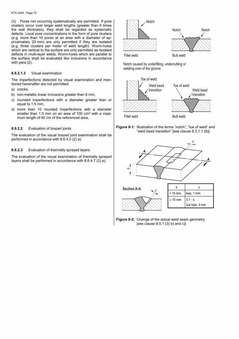
KTA 3204 Page 72
(3) Pores not occurring systematically are permitted. If pore clusters occur over larger weld lengths (greater than 6 times the wall thickness), they shall be regarded as systematic defects. Local pore concentrations in the form of pore clusters (e.g. more than 10 pores at an area with a diameter of ap-proximately 20 mm) are only permitted if they are isolated (e.g. three clusters per meter of weld length). Worm-holes which are vertical to the surface are only permitted as isolated defects in multi-layer welds. Worm-holes which are parallel to the surface shall be evaluated like inclusions in accordance with para (2).
8.9.2.1.3 Visual examination
The imperfections detected by visual examination and men-tioned hereinafter are not permitted: a) cracks, b) non-metallic linear inclusions greater than 6 mm, c) rounded imperfections with a diameter greater than or
equal to 1.5 mm, d) more than 10 rounded imperfections with a diameter
smaller than 1.5 mm on an area of 100 cm2 with a maxi-mum length of 60 cm of the referenced area.
8.9.2.2 Evaluation of brazed joints
The evaluation of the visual brazed joint examination shall be performed in accordance with 8.6.4.5 (2) a).
8.9.2.3 Evaluation of thermally sprayed layers
The evaluation of the visual examination of thermally sprayed layers shall be performed in accordance with 8.6.4.7 (2) a).
Toe of weldWeld beadtransition
Toe of weld
Fillet weld
Notch
Fillet weld
NotchNotch
Butt weld
Butt weld
Notch caused by underfilling, undercutting orwelding-over of the groove
Weld beadtransition
Figure 8-1: Illustration of the terms �notch�, �toe of weld� and �weld bead transition� [see clause 8.3.1.1 (8)]
Section A-A
A
A
s
c
c
Figure 8-2: Change of the actual weld seam geometry [see clause 8.5.1 (3) b) and c)]
s c < 10 mm max. 1 mm
≥ 10 mm 0.1 ⋅ s but max. 3 mm
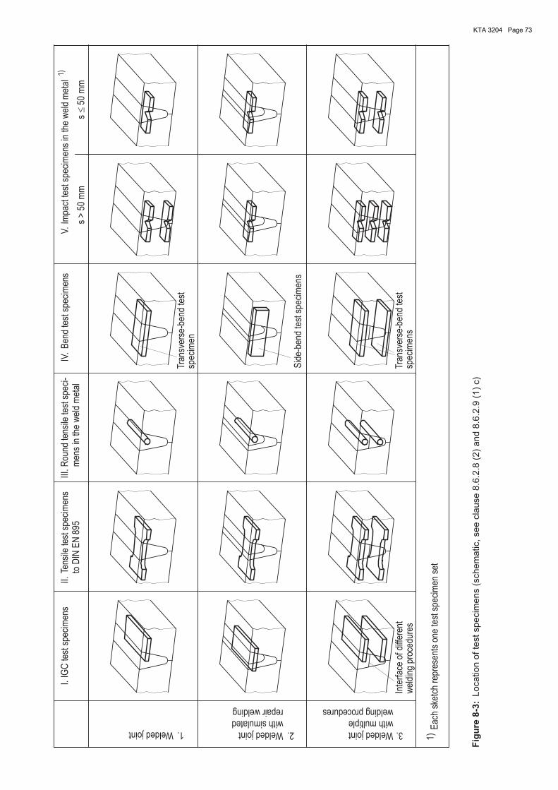
KTA 3204 Page 73
Location
ofte
stspecim
ens
(schem
atic,see
cla
use
8.6
.2.8
(2)
and
8.6
.2.9
(1)
c)
Fig
ure
8-3
:
1)Weldedjoint 1. Weldedjoint
weldingproceduresrepairwelding
Tra
nsve
rse-
bend
test
Inte
rfac
eof
diffe
rent
wel
ding
proc
edur
es
Sid
e-be
ndte
stsp
ecim
ens
1)E
ach
sket
chre
pres
ents
one
test
spec
imen
set
III. m
ens
inth
ew
eld
met
alIV
.R
ound
tens
ilete
stsp
eci-
toD
INE
N89
5IG
Cte
stsp
ecim
ens
I.II.
Tens
ilete
stsp
ecim
ens
3.Weldedjointwithsimulated
2.withmultiple
s>
50m
m
Ben
dte
stsp
ecim
ens
Impa
ctte
stsp
ecim
ens
inth
ew
eld
met
alV
.
spec
imen
s
Tra
nsve
rse-
bend
test
spec
imen
s50
mm
�
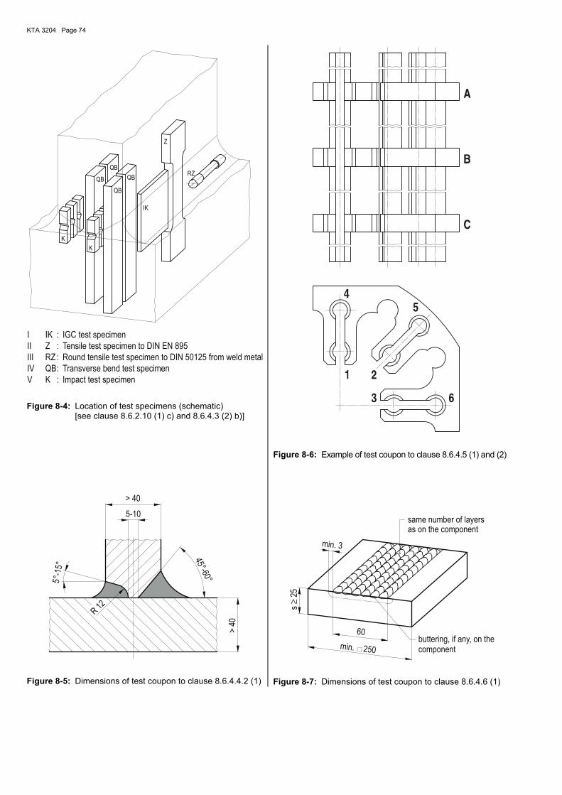
KTA 3204 Page 74
K
K
QB
QB
QB
IK
RZQB
Z
V
IV
IK
:
:
:
:
:
K
IGC test specimen
Tensile test specimen to DIN EN 895Z
RZ
QB
II
I
III Round tensile test specimen to DIN 50125 from weld metal
Transverse bend test specimen
Impact test specimen
Figure 8-4: Location of test specimens (schematic) [see clause 8.6.2.10 (1) c) and 8.6.4.3 (2) b)]
R12
5-10
>40
> 40
5°-1
5°
45°-60°
Figure 8-5: Dimensions of test coupon to clause 8.6.4.4.2 (1)
Figure 8-6: Example of test coupon to clause 8.6.4.5 (1) and (2)
≥s
25
250min.
60
min. 3
buttering, if any, on thecomponent
as on the componentsame number of layers
Figure 8-7: Dimensions of test coupon to clause 8.6.4.6 (1)
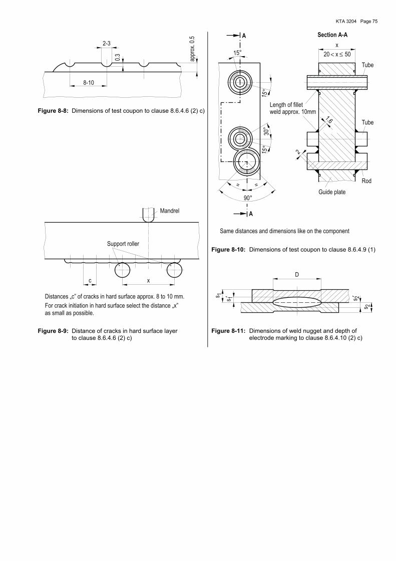
KTA 3204 Page 75
2-3
appr
ox.0
.5
8-10
0.3
Figure 8-8: Dimensions of test coupon to clause 8.6.4.6 (2) c)
as small as possible.For crack initiation in hard surface select the distance „x”
c x
Distances „c” of cracks in hard surface approx. 8 to 10 mm.
Support roller
Mandrel
Figure 8-9: Distance of cracks in hard surface layer to clause 8.6.4.6 (2) c)
≤<
Tube
Tube
2
Rod
Guide plate
Same distances and dimensions like on the component
Section A-AA
A
1.6
15°
30°
15°
90°
==
x
50
Length of filletweld approx. 10mm
15°
20 x
Figure 8-10: Dimensions of test coupon to clause 8.6.4.9 (1)
′′ 2
2
1
1s
D
s
s
s
Figure 8-11: Dimensions of weld nugget and depth of electrode marking to clause 8.6.4.10 (2) c)
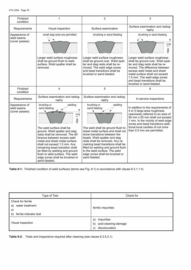
KTA 3204 Page 76
Finished condition
1 2 3
Requirements Visual inspection Surface examination Surface examination and radiog-
raphy
Appearance of weld seams (cover passes)
small slag rests are permitted
Larger weld surface roughness shall be ground flush to weld surface. Weld spatter shall be removed.
brushing or sand blasting
Larger weld surface roughness shall be ground over. Weld spat-ter and slag rests shall be re-moved. The weld edge zones and bead transitions shall be brushed or sand blasted.
brushing or sand blasting
max
.1.5
Larger weld surface roughness shall be ground over. Weld spat-ter and slag rests shall be re-moved. The difference between excess weld metal and sheet metal surface shall not exceed 1.5 mm. The weld edge zones and bead transitions shall be brushed or sand blasted.
Finished condition
4 5 6
Requirements Surface examination and radiog-
raphy Surface examination and radiog-
raphy In-service inspections
Appearance of weld seams (cover passes)
weldingbrushing orsand blasting
max
.1.5
The weld surface shall be ground. Weld spatter and slag rests shall be removed. The dif-ference between excess weld metal and sheet metal surface shall not exceed 1.5 mm. Any remaining bead transition shall be filled by welding and ground flush to weld surface. The weld edge zones shall be brushed or sand blasted.
weldingbrushing orsand blasting
The weld shall be ground flush to sheet metal surface and shall not show transitions between the beads. Weld spatter and slag rests shall be removed. Any re-maining bead transitions shall be filled by welding and ground flush to the weld surface. The weld edge zones shall be brushed or sand blasted.
In addition to the requirements of 4 or 5 large-area roughness (waviness) referred to an area of 50 mm x 50 mm shall not exceed 1 mm. In the vicinity of weld edge zones and bead transitions addi-tional local cavities of not more than 0.5 mm are permitted.
Table 8-1: Finished condition of weld surfaces (terms see Fig. 8-1) in accordance with clause 8.3.1.1 h)
Type of Test Check for
Check for ferrite a) water treatment or b) ferrite indicator test
ferritic impurities
Visual inspection
a) impurities b) acid-cleaning damage c) discolouration
Table 8-2: Tests and inspections required after cleaning (see clause 8.3.5.2.1)
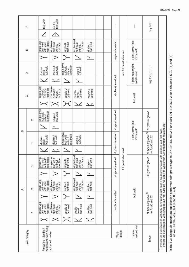
KTA 3204 Page 77
butt
wel
dbu
ttw
eld
Pro
cedu
requ
alifi
catio
npe
rfor
med
AB
CD
EF
12
31
2
Join
t cat
egor
y
Sym
bol /
wel
dde
sig-
natio
n
Wel
dde
sign
Type
ofw
elde
djo
int
Sco
pe
doub
le-v
eebu
ttw
eld
with
wid
ero
otfa
ces
doub
le-v
eebu
ttw
eld
with
wid
ero
otfa
ces
sing
le-v
eebu
ttw
eld
with
wid
ero
otfa
ces
sing
le-v
eebu
ttw
eld
with
wid
ero
otfa
ces
sing
le-v
eebu
ttw
eld
with
wid
ero
otfa
ces
doub
le-
beve
lbu
ttw
eld
doub
le-
beve
lbu
ttw
eld
doub
le-
beve
lbu
ttw
eld
doub
le-
beve
lbu
ttw
eld
doub
le-v
eebu
ttw
eld
with
out
root
face
doub
le-v
eebu
ttw
eld
with
out
root
face
sing
le-v
eebu
ttw
eld
with
out
root
face
sing
le-v
eebu
ttw
eld
with
out
root
face
sing
le-v
eebu
ttw
eld
with
out
root
face
doub
le-J
butt
wel
d
doub
le-J
butt
wel
ddo
uble
-Jbu
ttw
eld
doub
le-J
butt
wel
d
fille
t wel
d
doub
lefil
let w
eld
sing
le-U
butt
wel
dsi
ngle
-Ubu
ttw
eld
sing
le-U
butt
wel
d
sing
le-b
evel
butt
wel
dw
ithou
tro
otfa
ces
sing
le-b
evel
butt
wel
dw
ithou
tro
otfa
ces
sing
le-b
evel
butt
wel
dw
ithou
tro
otfa
ces
sing
le-b
evel
butt
wel
dw
ithou
tro
otfa
ces
sing
le-J
butt
wel
d
sing
le-J
butt
wel
d
sing
le-J
butt
wel
d
sing
le-J
butt
wel
dsi
ngle
-Jbu
ttw
eld
sing
le-b
evel
butt
wel
dw
ithou
tro
otfa
ces
sing
le-b
evel
butt
wel
dw
ithou
tro
otfa
ces
sing
le-J
butt
wel
d
doub
le-U
butt
wel
ddo
uble
-Ubu
ttw
eld
doub
lesi
dew
elde
ddo
uble
side
wel
ded
doub
lesi
dew
elde
dsi
ngle
side
wel
ded
sing
lesi
dew
elde
dsi
ngle
side
wel
ded
full
pene
trat
ion
wel
dno
nfu
llpe
netr
atio
nw
eld
all t
ypes
ofgr
oove
not f
orA
3an
dB
2
1)al
l typ
esof
groo
veal
l typ
esof
groo
veno
t for
A3
and
B2
1)al
l typ
esof
groo
ve
T-jo
int,
corn
erjo
int
nozz
lew
eld
T-jo
int,
corn
erjo
int
nozz
lew
eld
T-jo
int,
corn
erjo
int
nozz
lew
eld
only
for
C, D
, E, F
only
for
F
1)
Pro
cedure
qualif
ications
with
fully
penetr
ating
rootpass
als
oapply
tow
eld
sw
ith
chip
ped-o
utro
otpass.
Pro
cedure
qualif
ications
with
chip
ped-o
utro
otpass
do
notapply
tow
eld
sw
ith
fully
penetr
ating
rootpasses.
Tab
le8-3
:S
cope
ofpro
cedure
qualif
ication
perf
orm
ed
with
gro
vve
type
to[s
ee
cla
uses
8.6
.2.7
(3)
and
(4)
as
well
as
cla
uses
8.6
.4.3
and
8.6
.4.4
]D
INE
NIS
O9692-1
and
DIN
EN
ISO
9692-2
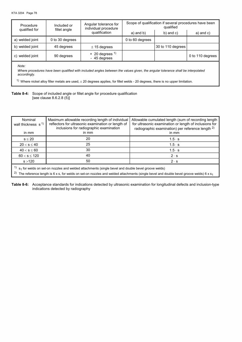
KTA 3204 Page 78
Scope of qualification if several procedures have been qualified Procedure
qualified for Included or fillet angle
Angular tolerance for individual procedure
qualification a) and b) b) and c) a) and c)
a) welded joint 0 to 30 degrees 0 to 60 degrees
b) welded joint 45 degrees ± 15 degrees 30 to 110 degrees
c) welded joint 90 degrees + 20 degrees 1) - 45 degrees
0 to 110 degrees
Note: Where procedures have been qualified with included angles between the values given, the angular tolerance shall be interpolated accordingly.
1) Where nickel alloy filler metals are used, ± 20 degrees applies, for fillet welds - 20 degrees, there is no upper limitation.
Table 8-4: Scope of included angle or fillet angle for procedure qualification [see clause 8.6.2.8 (5)]
Nominal
wall thickness s 1)
in mm
Maximum allowable recording length of individual reflectors for ultrasonic examination or length of
inclusions for radiographic examination in mm
Allowable cumulated length (sum of recording length for ultrasonic examination or length of inclusions for
radiographic examination) per reference length 2) in mm
s ≤ 20 20 1.5 ⋅ s 20 < s ≤ 40 25 1.5 ⋅ s 40 < s ≤ 60 30 1.5 ⋅ s
60 < s ≤ 120 40 2 ⋅ s s >120 50 2 ⋅ s
1) s1 for welds on set-on nozzles and welded attachments (single bevel and double bevel groove welds) 2) The reference length is 6 x s, for welds on set-on nozzles and welded attachments (single bevel and double bevel groove welds) 6 x s1
Table 8-6: Acceptance standards for indications detected by ultrasonic examination for longitudinal defects and inclusion-type indications detected by radiography
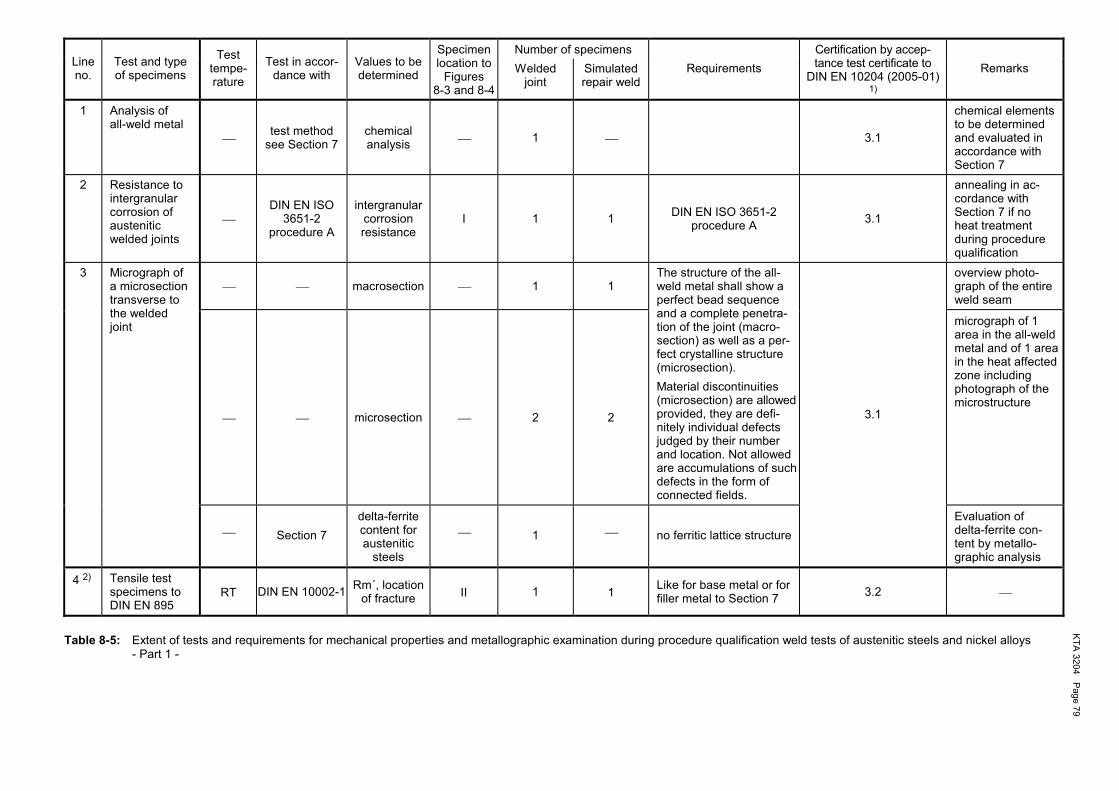
KTA
3204 Page 79
Number of specimens Line no.
Test and type of specimens
Test tempe-rature
Test in accor-dance with
Values to be determined
Specimen location to
Figures 8-3 and 8-4
Welded joint
Simulated repair weld
Requirements Certification by accep-tance test certificate to
DIN EN 10204 (2005-01)
1)
Remarks
1 Analysis of all-weld metal
test method see Section 7
chemical analysis 1 3.1
chemical elements to be determined and evaluated in accordance with Section 7
2 Resistance to intergranular corrosion of austenitic welded joints
DIN EN ISO
3651-2 procedure A
intergranular corrosion resistance
I 1 1 DIN EN ISO 3651-2 procedure A 3.1
annealing in ac-cordance with Section 7 if no heat treatment during procedure qualification
3 macrosection 1 1
overview photo-graph of the entire weld seam
Micrograph of a microsection transverse to the welded joint
microsection
2
2
The structure of the all-weld metal shall show a perfect bead sequence and a complete penetra-tion of the joint (macro-section) as well as a per-fect crystalline structure (microsection). Material discontinuities (microsection) are allowedprovided, they are defi-nitely individual defects judged by their number and location. Not allowed are accumulations of such defects in the form of connected fields.
micrograph of 1 area in the all-weld metal and of 1 area in the heat affected zone including photograph of the microstructure
Section 7
delta-ferrite content for austenitic
steels
1
no ferritic lattice structure
3.1
Evaluation of delta-ferrite con-tent by metallo-graphic analysis
4 2) Tensile test specimens to DIN EN 895
RT DIN EN 10002-1 Rm´, location of fracture II 1 1 Like for base metal or for
filler metal to Section 7 3.2
Table 8-5: Extent of tests and requirements for mechanical properties and metallographic examination during procedure qualification weld tests of austenitic steels and nickel alloys - Part 1 -
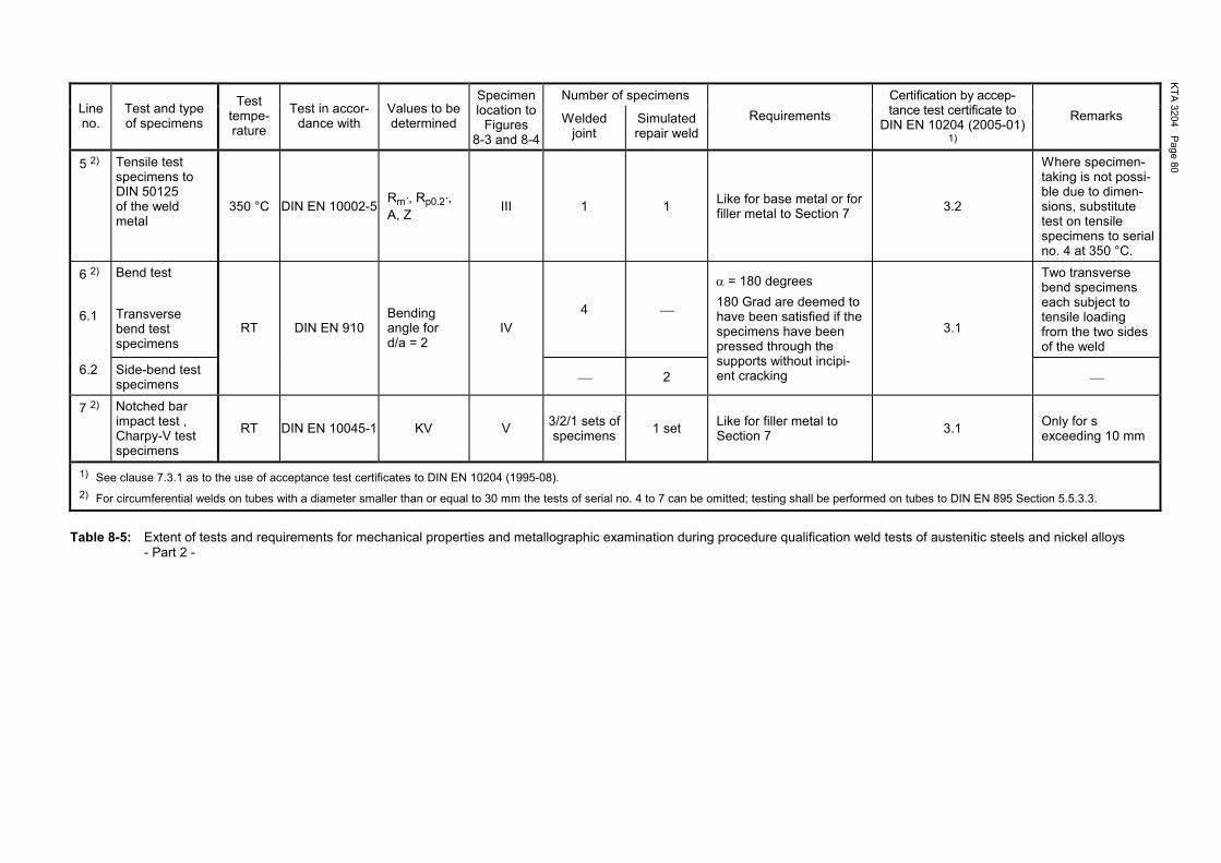
KTA
3204 Page 80
Number of specimens Line no.
Test and type of specimens
Test tempe-rature
Test in accor-dance with
Values to be determined
Specimen location to
Figures 8-3 and 8-4
Welded joint
Simulated repair weld
Requirements Certification by accep-tance test certificate to
DIN EN 10204 (2005-01)
1)
Remarks
5 2) Tensile test specimens to DIN 50125 of the weld metal
350 °C DIN EN 10002-5Rm´, Rp0.2´, A, Z III 1 1 Like for base metal or for
filler metal to Section 7 3.2
Where specimen-taking is not possi-ble due to dimen-sions, substitute test on tensile specimens to serial no. 4 at 350 °C.
6 2) 6.1
Bend test Transverse bend test specimens
4
Two transverse bend specimens each subject to tensile loading from the two sides of the weld
6.2 Side-bend test specimens
RT DIN EN 910 Bending angle for d/a = 2
IV
2
α = 180 degrees 180 Grad are deemed to have been satisfied if the specimens have been pressed through the supports without incipi-ent cracking
3.1
7 2) Notched bar impact test , Charpy-V test specimens
RT DIN EN 10045-1 KV V 3/2/1 sets of specimens 1 set Like for filler metal to
Section 7 3.1 Only for s exceeding 10 mm
1) See clause 7.3.1 as to the use of acceptance test certificates to DIN EN 10204 (1995-08). 2) For circumferential welds on tubes with a diameter smaller than or equal to 30 mm the tests of serial no. 4 to 7 can be omitted; testing shall be performed on tubes to DIN EN 895 Section 5.5.3.3.
Table 8-5: Extent of tests and requirements for mechanical properties and metallographic examination during procedure qualification weld tests of austenitic steels and nickel alloys - Part 2 -
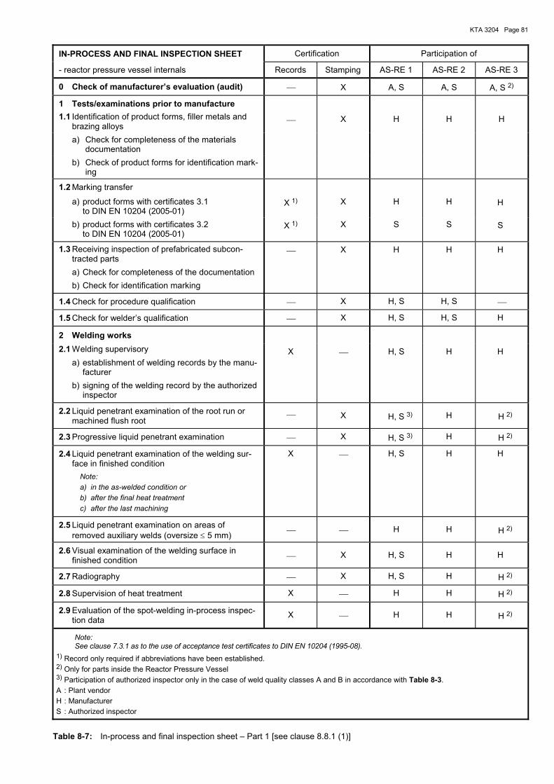
KTA 3204 Page 81
IN-PROCESS AND FINAL INSPECTION SHEET Certification Participation of
- reactor pressure vessel internals Records Stamping AS-RE 1 AS-RE 2 AS-RE 3
0 Check of manufacturer�s evaluation (audit) X A, S A, S A, S 2)
1 Tests/examinations prior to manufacture 1.1 Identification of product forms, filler metals and
brazing alloys X H H H
a) Check for completeness of the materials documentation
b) Check of product forms for identification mark-ing
1.2 Marking transfer
a) product forms with certificates 3.1 to DIN EN 10204 (2005-01)
X 1) X H H H
b) product forms with certificates 3.2 to DIN EN 10204 (2005-01)
X 1) X S S S
1.3 Receiving inspection of prefabricated subcon-tracted parts a) Check for completeness of the documentation b) Check for identification marking
X H H H
1.4 Check for procedure qualification X H, S H, S
1.5 Check for welder�s qualification X H, S H, S H
2 Welding works
2.1 Welding supervisory a) establishment of welding records by the manu-
facturer b) signing of the welding record by the authorized
inspector
X H, S H H
2.2 Liquid penetrant examination of the root run or machined flush root
X H, S 3) H H 2)
2.3 Progressive liquid penetrant examination X H, S 3) H H 2)
2.4 Liquid penetrant examination of the welding sur-face in finished condition
Note: a) in the as-welded condition or b) after the final heat treatment c) after the last machining
X H, S H H
2.5 Liquid penetrant examination on areas of removed auxiliary welds (oversize ≤ 5 mm) H H H 2)
2.6 Visual examination of the welding surface in finished condition X H, S H H
2.7 Radiography X H, S H H 2)
2.8 Supervision of heat treatment X H H H 2)
2.9 Evaluation of the spot-welding in-process inspec-tion data X H H H 2)
Note: See clause 7.3.1 as to the use of acceptance test certificates to DIN EN 10204 (1995-08).
1) Record only required if abbreviations have been established. 2) Only for parts inside the Reactor Pressure Vessel 3) Participation of authorized inspector only in the case of weld quality classes A and B in accordance with Table 8-3. A : Plant vendor H : Manufacturer S : Authorized inspector
Table 8-7: In-process and final inspection sheet � Part 1 [see clause 8.8.1 (1)]
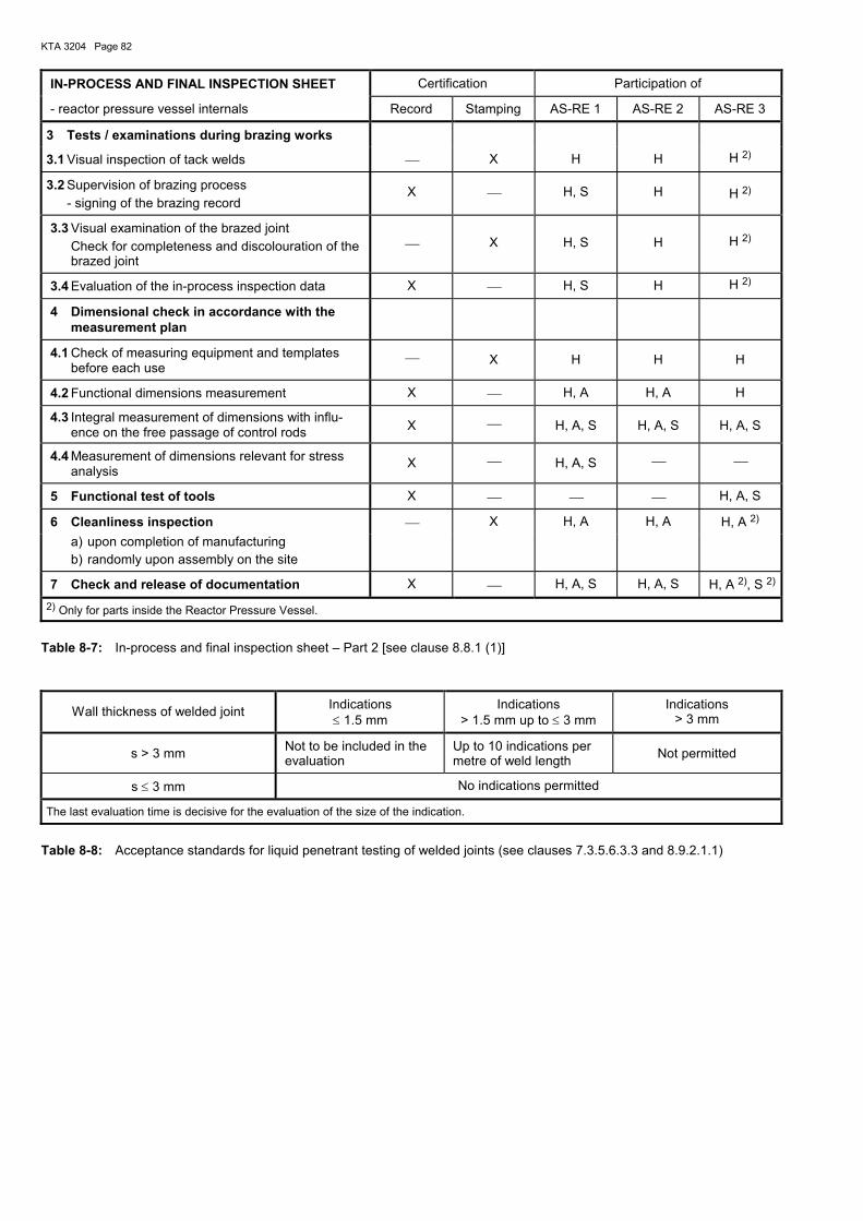
KTA 3204 Page 82
IN-PROCESS AND FINAL INSPECTION SHEET Certification Participation of
- reactor pressure vessel internals Record Stamping AS-RE 1 AS-RE 2 AS-RE 3
3 Tests / examinations during brazing works
3.1 Visual inspection of tack welds X H H H 2)
3.2 Supervision of brazing process - signing of the brazing record
X H, S H H 2)
3.3 Visual examination of the brazed joint Check for completeness and discolouration of the
brazed joint
X
H, S
H
H 2)
3.4 Evaluation of the in-process inspection data X H, S H H 2)
4 Dimensional check in accordance with the measurement plan
4.1 Check of measuring equipment and templates before each use
X H H H
4.2 Functional dimensions measurement X H, A H, A H
4.3 Integral measurement of dimensions with influ-ence on the free passage of control rods X H, A, S H, A, S H, A, S
4.4 Measurement of dimensions relevant for stress analysis X H, A, S
5 Functional test of tools X H, A, S
6 Cleanliness inspection X H, A H, A H, A 2) a) upon completion of manufacturing b) randomly upon assembly on the site
7 Check and release of documentation X H, A, S H, A, S H, A 2), S 2)
2) Only for parts inside the Reactor Pressure Vessel.
Table 8-7: In-process and final inspection sheet � Part 2 [see clause 8.8.1 (1)]
Wall thickness of welded joint Indications ≤ 1.5 mm
Indications > 1.5 mm up to ≤ 3 mm
Indications > 3 mm
s > 3 mm Not to be included in the evaluation
Up to 10 indications per metre of weld length Not permitted
s ≤ 3 mm No indications permitted
The last evaluation time is decisive for the evaluation of the size of the indication.
Table 8-8: Acceptance standards for liquid penetrant testing of welded joints (see clauses 7.3.5.6.3.3 and 8.9.2.1.1)
KTA 3204 Page 83
9 Operational monitoring and inspection
9.1 Scope
This section covers the inspections and measurements to be performed and the monitoring of reactor pressure vessel in-ternals during commissioning, operation and refuelling.
9.2 Points in time of inspection
Table 9-1 contains a list of points in time of inspection as well as data for pressurized water reactors to specify which in-spections may be or shall be performed at the mentioned points in time. The points in time at which vibration measure-ments and inspections have to be performed are necessarily bound to the individual steps of commissioning. Depending on which commissioning steps are to be taken, differing proce-dures are to be followed.
9.3 Inspections
9.3.1 General requirements
(1) At the points in time specified in Table 9-1, the compo-nents shall be subjected to the inspections specified in Ta-bles 9-2 to 9-5. In this case the inspections prescribed for point in time B in Tables 9-2 and 9-3 may be performed in full or in part already at the time of completion of fabrication on the site.
(2) The components mentioned are shown in Figure 3-1 for typical reactor pressure vessel internals for pressurized water reactors and in Figure 3-2 for typical reactor pressure vessel internals for boiling water reactors.
(3) The inspections mentioned in Tables 9-2 to 9-5 may also be performed simultaneously during one inspection step.
(4) Additional disassembly of RPV internals or other compo-nents in the reactor pressure vessel in excess of the planned inspections is not required for the performance of the integral visual examination in accordance with Tables 9-2 to 9-5. For the selective visual examination as per Tables 9-2 to 9-5 the disassembly of additional components in the RPV may be required. The extent of these required measures shall be fixed with respect to the plant in consideration of the planned in-spection activities, especially in the case of the operationally required disassembly of RPV internals or e.g. internal axial pumps or fuel assembly peripheral location. The knowledge on the materials used, the fabrication, the operational load-ings on the RPV internals shall be considered when fixing the plant-related extent of selective visual inspections. It is permit-ted to limit selective visual examinations to representative locations of RPV internals.
(5) At each refuelling, a selective visual examination shall be performed at the load attachment points of components the disassembly of which is required for operational reasons with the components located on the internals storage pit. Load-attachment points of components the disassembly of which is not required for operational reasons, shall be subjected to a selective visual examination prior to using them. Where defects impairing safety are detected, the load-attachment points shall not be used until removal of the defects.
9.3.2 Requirements for visual examination
(1) DIN 25435-4 applies regarding the requirements for the inspection procedure, inspection personnel, the authorized inspector involved and auxiliary equipment used as well as for the performance of visual examinations.
(2) To provide a basis for comparison of integral visual ex-aminations, image records (e.g. photographs, video records)
shall be made prior to the first trial run. The details shall be fixed in relation to the plant.
(3) The selective visual examination for cracks shall guaran-tee that details of a wire with a diameter 0.025 mm or actual cracks in a reference block can be recognized. The reference block shall consider the surface condition of the areas to be inspected. The recognizability of details with the equipment used including the required boundary conditions, such as distance, orientation, lighting equipment selected shall be documented.
9.3.3 Inspection sequence program for inspections
(1) The inspections and examinations to be performed in accordance with Tables 9-2 to 9-5 shall be listed in a plant-related test and inspection sequence program. The plant-related test and inspection sequence program shall contain at least the following information: a) the exact inspection areas, b) the inspection intervals, c) the extent of inspection for each component, sub-unit or
part, which within the inspection interval may be subdi-vided into partial inspections,
d) the inspections and examinations to be performed after each refuelling cycle (e.g. integral visual examination for presence of foreign matter),
e) the mechanized inspection equipment, f) the parties involved in the inspection.
(2) The tests and inspections to be performed at points in F and G shall be entered in the test and inspection handbook. The requirements of KTA 1202 shall be considered.
(3) The inspection intervals shall be fixed in consideration of the in-service test and inspection intervals on the reactor pressure vessel.
(4) When determining the type and extent as well as loca-tions of tests and inspections to be performed for the ap-proaching refuelling activities, the results of vibration and loose-parts monitoring shall be evaluated to find out whether relevant changes with respect to former results of operational monitoring are available and have to be evaluated.
9.3.4 Assessment of as-built condition
Where particularities are detected by the inspections, deci-sion shall be made in each individual case whether and which additional examinations and measures are required (e. g. increase of extent of inspections, use of supplementary ex-amination procedures). Dimensional checks and functional tests are considered to have been satisfied if the values specified for the inspection have been obtained.
Note: The images recorded of representative locations as per clause 9.3.3 serve as reference for the selective visual and the other in-spections. When assessing the as-built condition, it shall be taken into ac-count that components are subject to changes of the surface dur-ing plant operation (e.g. discolouration, flow marks, die marks due to handling).
9.3.5 Documentation of inspections
(1) A record shall be established on each inspection per-formed to document the type, extent, auxiliary and other equipment used, as well as the results of the inspections including the deviations, if any, from the reference condition (e.g. by photographs).
KTA 3204 Page 84
(2) The documentation shall be made in accordance with Section 5. DIN 25435-4 applies with respect to the extent of documentation.
(3) The inspections of the load-attachment points and the repair work performed shall be documented in accordance with Section 5.
9.4 Vibration measurements
9.4.1 General requirements
For reactor pressure vessel internals it shall be proved that they are capable of withstanding the permanent or temporary vibration loadings during the reactor service life. For compo-nents of quality class AS-RE 2 vibratory loadings shall only be determined if no operational experience with these components exist. In the following only experimental measures are dealt with to demonstrate the acceptability of operational vibratory loadings. The stress analysis is dealt with in Section 6.2. The experimental analysis (vibration measurement program) is an alternative to substitute an analytical proof. The meas-urement program may deliver: a) dynamic characteristics, e.g. natural frequency, and b) dynamic load and stress values for selected measurement
location and measured values, which occur during the possible operational conditions.
9.4.2 Classification of reactor pressure vessel internals for vibration measurements
With respect to the objectives of the vibration measurement program there are differing requirements as to its extent which depends on the extent of assured knowledge of the character-istic and stress values required for the structural analysis and the stress analysis. To this end, reactor pressure vessel inter-nals shall be classified into various classes with respect to vibration measurements depending on the design, operational parameters and experience:
(1) Prototype plant An arrangement of reactor pressure vessel internals which due to their design, size or operating conditions represent the first plant of this kind for which no reference plant is available.
(2) Reference plant A plant for which a vibration measurement program was per-formed successfully with the result during commissioning no inadmissible dynamic loadings occurred.
(3) Modified prototype plant An arrangement of reactor pressure vessel internals the load-ings or operating conditions of which deviate in part from the reference plant and where in some cases it cannot be dem-onstrated by available measuring results and analyses or a combination of measuring results and analyses, that devia-tions from the reference plant do not have any essential influ-ence on the dynamic behaviour of the reactor pressure vessel internals.
(4) Follow-up plant An arrangement of reactor pressure vessel internals with essentially the same loading and operating conditions as well as the same design dimensions as the reference plant. By available measuring results and analyses it can be demon-strated that deviations, if any, do not have an essential influ-ence on the dynamic behaviour of the reactor pressure vessel internals.
9.4.3 Measures
The structural analysis (6.2.4.2) or the experimental fatigue analysis (6.2.4.3.5) may be replaced by the vibration mea-surement program and the inspection sequence program to 9.3.3 for inspection points in time A to F to Table 9-1.
9.4.3.1 Vibration measurement program for prototype plant
During commissioning a vibration measurement program shall be performed to demonstrate dynamic loadings and the re-sulting dynamic movements and loadings occurring during steady-state and non-steady-state normal operation.
(1) Test program Prior to the beginning of measurements a test program shall be established to describe: a) the locations and orientations of measurement as well as
the measured variables including the frequency and ampli-tude ranges to be considered. The locations of mea-surement shall be selected such that all movements, loa-dings and stresses of the component required for experi-mental fatigue evaluation are covered.
b) the measurement procedure to indicate which signals are to be processed, stored and indicated in which way. In ad-dition, it shall be indicated which signals are to be evalu-ated in which way immediately on the site to ensure the required measuring quality and to avoid inadmissible dy-namic loadings.
c) the steady-state and non-steady-state operating condi-tions at which measurements are to be made as well as - assigned to the operating conditions - the duration of re-cording (measuring time).
d) the planned duration of operation under normal operating conditions to ensure that each component subject to dy-namic loading has been subjected to at least 106 load cy-cles (for the lowest frequency at which the component shows a considerable frequency response) prior to the fi-nal inspection of the RPV internals.
e) the sensors and their characteristic data including usable frequency and amplitude values.
f) the equipment for signal processing, storage, indication and evaluation with respect to the properties influencing the quality of the results.
g) deviations, if any, from normal operating conditions. h) further boundary conditions influencing the measuring
result.
(2) Performance of measurements The measurements shall be made to comply with the test program. Where unexpected measured values are taken, the responsible head of the test program shall supplement or modify the test program. Where required, recommendations regarding the various operating conditions shall be given to the person responsible for operation or structural analysis.
(3) Documentation of results The results of the measurements made including all consid-erable deviations from the test program as well as defaults on the measuring equipment that have occurred during the measuring process shall be documented. The results of the measurements and the inspections to Sec-tion 9.2 shall be correlated..
9.4.3.2 Vibration measurement program for modified proto-type plant
(1) The extent of the measuring program may be reduced to a representative movement or loading (control measurement) if it can be shown by comparison of the magnitudes relevant
KTA 3204 Page 85
to vibration behaviour that the deviations compared to a valid reference plant are negligible.
(2) If this proof cannot be rendered partially the measure-ment shall be extended such that besides the control meas-urement for the proved component sufficient experimental data are also available for the part deviating from the refe-rence plant.
(3) The requirements of 9.4.3.1 apply to the control pro-gram, performance of measurements and documentation of results.
9.4.3.3 Vibration measurement program for follow-up plants
For follow-up plants no vibration measurement program is required.
9.5 Vibration monitoring
(1) For the early detection of changes in the vibration be-haviour of reactor pressure vessel internals the latter shall be monitored during operation.
(2) In pressurized water reactors the system shall be de-signed and monitoring be performed in accordance with DIN 25475-2.
(3) Monitoring shall be performed such that changes in the vibration behaviour can be detected at a representative loca-tion of the reactor pressure vessel internals.
Note: The information is obtained by indirect measuring procedures (e.g. by measuring the neutron flux noise or the reactor pressure vessel movement). With these measuring methods correspondence to the measure variables to be monitored shall be established.
(4) It shall be possible to perform vibration measurements at any time. Vibration measurements may be performed discon-tinuously.
(5) At least three measurements shall be performed during each fuel cycle. One of these measurements shall be per-formed immediately after refuelling and one prior to the next refuelling at steady-state operation of the nuclear facility.
Note: It is advisable to install a fixed vibration monitoring system such that the required measurements can be performed without addi-tional installations.
(6) Where vibration monitoring is entirely or partially impos-sible due to failure of the measuring devices, it may be sus-pended until the next plant shutdown.
(7) The measures for performing vibration measurements as well as the measures to be taken if changes in the vibration behaviour of the reactor pressure vessel internals are de-tected, shall be fixed for each individual plant.
Note: At the time being, there is no safeguarded indirect measuring method available for boiling water reactors.
9.6 Monitoring for loose parts
(1) For the early detection of damage the reactor pressure vessel internals shall be monitored for loose parts by means of a structure-borne sound measuring system. This system shall be designed and monitoring be performed in accordance with DIN 25475-1.
(2) Even in the case of failure of individual measuring chan-nels of the structure-borne-sound measuring system, monitor-ing is considered to be ensured as long as loose parts can be detected in each monitored area in compliance with DIN 25474-1.
(3) In the case of failure of the entire structure-borne-sound measuring system monitoring may temporarily be carried out by other measures (e.g. activity measurements and chemical analysis of the primary coolant, vibration measurements on components).
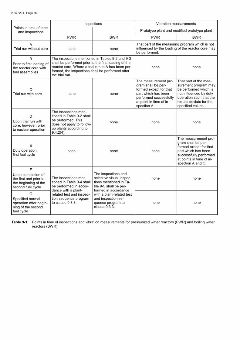
KTA 3204 Page 86
Inspections Vibration measurements
Prototype plant and modified prototype plant
Points in time of tests
and inspections PWR BWR PWR BWR
A Trial run without core
none
none
That part of the measuring program which is not influenced by the loading of the reactor core may be performed.
B Prior to first loading of the reactor core with fuel assemblies
The inspections mentioned in Tables 9-2 and 9-3 shall be performed prior to the first loading of the reactor core. Where a trial run to A has been per-formed, the inspections shall be performed after the trial run.
none none
C Trial run with core none none
The measurement pro-gram shall be per-formed except for that part which has been performed successfully at point in time of in-spection A.
That part of the mea-surement program may be performed which is not influenced by duty operation such that the results deviate for the specified values.
D
Upon trial run with core, however, prior to nuclear operation
The inspections men-tioned in Table 9-2 shall be performed. This does not apply to follow-up plants according to 9.4.2(4).
none none none
E
Duty operation, first fuel cycle
none none none
The measurement pro-gram shall be per-formed except for that part which has been successfully performed at points in time of in-spection A and C.
F Upon completion of the first and prior to the beginning of the second fuel cycle
none none
G Specified normal operation after begin-ning of the second fuel cycle
The inspections men-tioned in Table 9-4 shall be performed in accor-dance with a plant-related test and inspec-tion sequence program to clause 9.3.3.
The inspections and selective visual inspec-tions mentioned in Ta-ble 9-5 shall be per-formed in accordance with a plant-related test and inspection se-quence program to clause 9.3.3.
none none
Table 9-1: Points in time of inspections and vibration measurements for pressurized water reactors (PWR) and boiling water reactors (BWR)
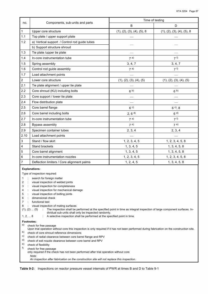
KTA 3204 Page 87
Time of testing no. Components, sub-units and parts
B D
1 Upper core structure (1), (2), (3), (4), (5), 8 (1), (2), (3), (4), (5), 8
1.1 Top plate / upper support plate
1.2 a) Vertical support / Control rod guide tubes
b) Support structure shroud
1.3 Tie plate /upper tie plate
1.4 In-core instrumentation tube 7 a) 7 f)
1.5 Spring assembly 3, 4, 7 3, 4, 7
1.6 Control rod guide assembly 7 a) 7 f)
1.7 Load attachment points
2 Lower core structure (1), (2), (3), (4), (5) (1), (2), (3), (4), (5)
2.1 Tie plate alignment / upper tie plate
2.2 Core shroud (KU) including bolts 6 b) 6 b)
2.3 Core support / lower tie plate
2.4 Flow distribution plate
2.5 Core barrel flange 6 c) 6 c), 8
2.6 Core barrel including bolts 2, 6 d) 6 d)
2.7 In-core instrumentation tube 7 a) 7 f)
2.8 Bypass assembly 7 e) 7 e)
2.9 Specimen container tubes 2, 3, 4 2, 3, 4
2.10 Load attachment points
3 Stand / flow skirt 1, 2, 3, 4, 5 1, 2, 3, 4, 5, 8
4 Stand brackets 1, 3, 4, 5 1, 3, 4, 5, 8
5 Core barrel alignment 1, 3, 4, 5 1, 3, 4, 5, 8
6 In-core instrumentation nozzles 1, 2, 3, 4, 5 1, 2, 3, 4, 5, 8
7 Deflection limiters / Core alignment palms 1, 2, 4, 5 1, 3, 4, 5, 8
Explanations: Type of inspection required: 1 : search for foreign matter 2 : visual inspection of welded joints 3 : visual inspection for completeness 4 : visual inspection for mechanical damage 5 : visual inspection of bolting joints 6 : dimensional check 7 : functional test 8 : visual inspection of mating surfaces (1), (2) ... (5) : The inspection shall be performed at the specified point in time as integral inspection of large component surfaces. In-
dividual sub-units shall only be inspected randomly. 1, 2, ... 8 : A selective inspection shall be performed at the specified point in time.
Footnotes: a) check for free passage Upon trial operation without core this inspection is only required if it has not been performed during fabrication on the construction site. b) check of core shroud reference dimensions c) check of radial clearance between core barrel flange and RPV d) check of exit nozzle clearance between core barrel and RPV e) check of flexibility f) check for free passage only required if the check has not been performed after trial operation without core
Note: An inspection after fabrication on the construction site will not replace this inspection.
Table 9-2: Inspections on reactor pressure vessel internals of PWR at times B and D to Table 9-1
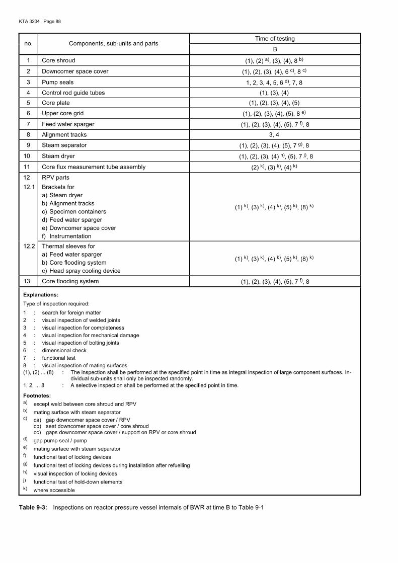
KTA 3204 Page 88
Time of testing no. Components, sub-units and parts
B
1 Core shroud (1), (2) a), (3), (4), 8 b)
2 Downcomer space cover (1), (2), (3), (4), 6 c), 8 c)
3 Pump seals 1, 2, 3, 4, 5, 6 d), 7, 8
4 Control rod guide tubes (1), (3), (4)
5 Core plate (1), (2), (3), (4), (5)
6 Upper core grid (1), (2), (3), (4), (5), 8 e)
7 Feed water sparger (1), (2), (3), (4), (5), 7 f), 8
8 Alignment tracks 3, 4
9 Steam separator (1), (2), (3), (4), (5), 7 g), 8
10 Steam dryer (1), (2), (3), (4) h), (5), 7 j), 8
11 Core flux measurement tube assembly (2) k), (3) k), (4) k)
12 12.1
RPV parts Brackets for a) Steam dryer b) Alignment tracks c) Specimen containers d) Feed water sparger e) Downcomer space cover f) Instrumentation
(1) k), (3) k), (4) k), (5) k), (8) k)
12.2 Thermal sleeves for a) Feed water sparger b) Core flooding system c) Head spray cooling device
(1) k), (3) k), (4) k), (5) k), (8) k)
13 Core flooding system (1), (2), (3), (4), (5), 7 f), 8
Explanations: Type of inspection required: 1 : search for foreign matter 2 : visual inspection of welded joints 3 : visual inspection for completeness 4 : visual inspection for mechanical damage 5 : visual inspection of bolting joints 6 : dimensional check 7 : functional test 8 : visual inspection of mating surfaces (1), (2) ... (8) : The inspection shall be performed at the specified point in time as integral inspection of large component surfaces. In-
dividual sub-units shall only be inspected randomly. 1, 2, ... 8 : A selective inspection shall be performed at the specified point in time.
Footnotes: a) except weld between core shroud and RPV b) mating surface with steam separator c) ca) gap downcomer space cover / RPV cb) seat downcomer space cover / core shroud cc) gaps downcomer space cover / support on RPV or core shroud d) gap pump seal / pump e) mating surface with steam separator f) functional test of locking devices g) functional test of locking devices during installation after refuelling h) visual inspection of locking devices j) functional test of hold-down elements k) where accessible
Table 9-3: Inspections on reactor pressure vessel internals of BWR at time B to Table 9-1
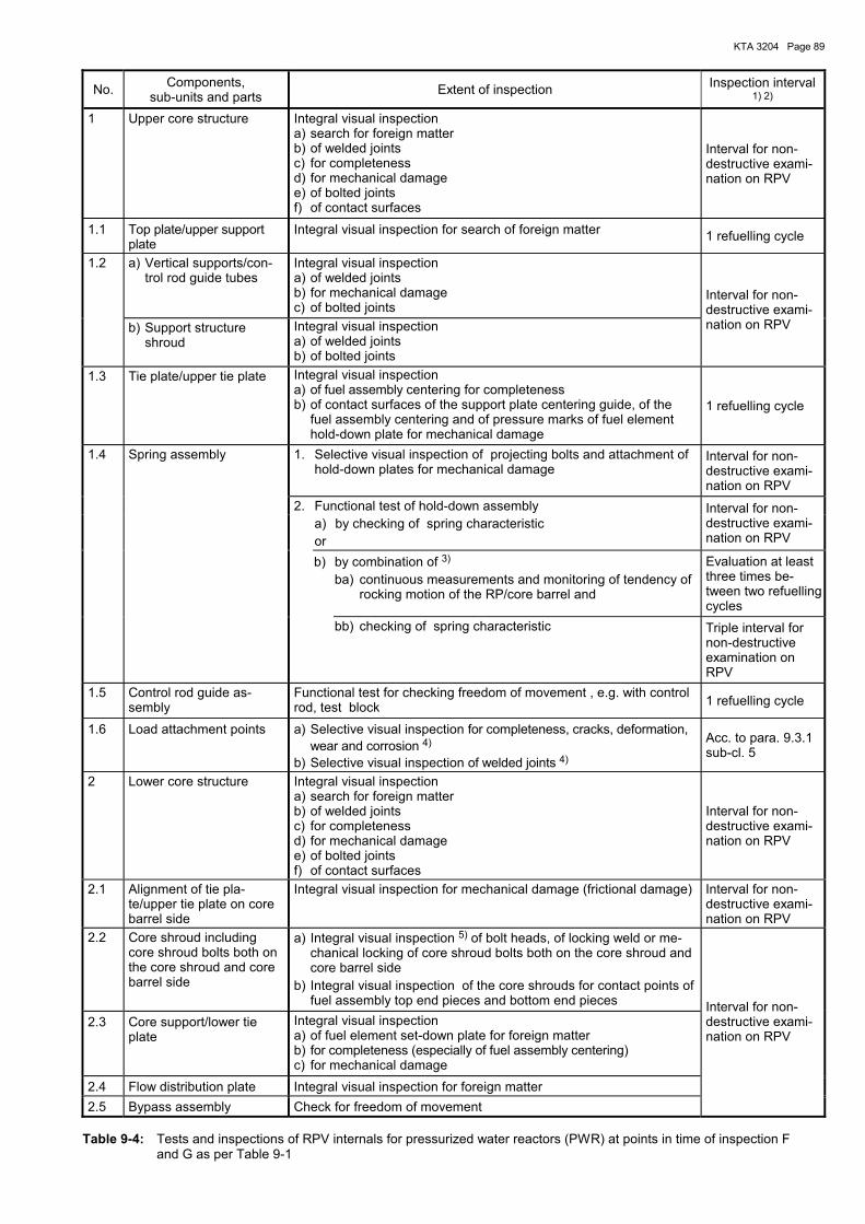
KTA 3204 Page 89
No. Components, sub-units and parts Extent of inspection Inspection interval
1) 2) 1 Upper core structure Integral visual inspection
a) search for foreign matter b) of welded joints c) for completeness d) for mechanical damage e) of bolted joints f) of contact surfaces
Interval for non-destructive exami-nation on RPV
1.1 Top plate/upper support plate
Integral visual inspection for search of foreign matter 1 refuelling cycle
1.2 a) Vertical supports/con-trol rod guide tubes
Integral visual inspection a) of welded joints b) for mechanical damage c) of bolted joints
b) Support structure shroud
Integral visual inspection a) of welded joints b) of bolted joints
Interval for non-destructive exami-nation on RPV
1.3 Tie plate/upper tie plate Integral visual inspection a) of fuel assembly centering for completeness b) of contact surfaces of the support plate centering guide, of the
fuel assembly centering and of pressure marks of fuel element hold-down plate for mechanical damage
1 refuelling cycle
1. Selective visual inspection of projecting bolts and attachment of hold-down plates for mechanical damage
Interval for non-destructive exami-nation on RPV
2. Functional test of hold-down assembly a) by checking of spring characteristic or
Interval for non-destructive exami-nation on RPV
b) by combination of 3) ba) continuous measurements and monitoring of tendency of
rocking motion of the RP/core barrel and
Evaluation at least three times be-tween two refuelling cycles
1.4 Spring assembly
bb) checking of spring characteristic Triple interval for non-destructive examination on RPV
1.5 Control rod guide as-sembly
Functional test for checking freedom of movement , e.g. with control rod, test block 1 refuelling cycle
1.6 Load attachment points a) Selective visual inspection for completeness, cracks, deformation, wear and corrosion 4)
b) Selective visual inspection of welded joints 4)
Acc. to para. 9.3.1 sub-cl. 5
2 Lower core structure Integral visual inspection a) search for foreign matter b) of welded joints c) for completeness d) for mechanical damage e) of bolted joints f) of contact surfaces
Interval for non-destructive exami-nation on RPV
2.1 Alignment of tie pla-te/upper tie plate on core barrel side
Integral visual inspection for mechanical damage (frictional damage) Interval for non-destructive exami-nation on RPV
2.2 Core shroud including core shroud bolts both on the core shroud and core barrel side
a) Integral visual inspection 5) of bolt heads, of locking weld or me-chanical locking of core shroud bolts both on the core shroud and core barrel side
b) Integral visual inspection of the core shrouds for contact points of fuel assembly top end pieces and bottom end pieces
2.3 Core support/lower tie plate
Integral visual inspection a) of fuel element set-down plate for foreign matter b) for completeness (especially of fuel assembly centering) c) for mechanical damage
2.4 Flow distribution plate Integral visual inspection for foreign matter 2.5 Bypass assembly Check for freedom of movement
Interval for non-destructive exami-nation on RPV
Table 9-4: Tests and inspections of RPV internals for pressurized water reactors (PWR) at points in time of inspection F and G as per Table 9-1
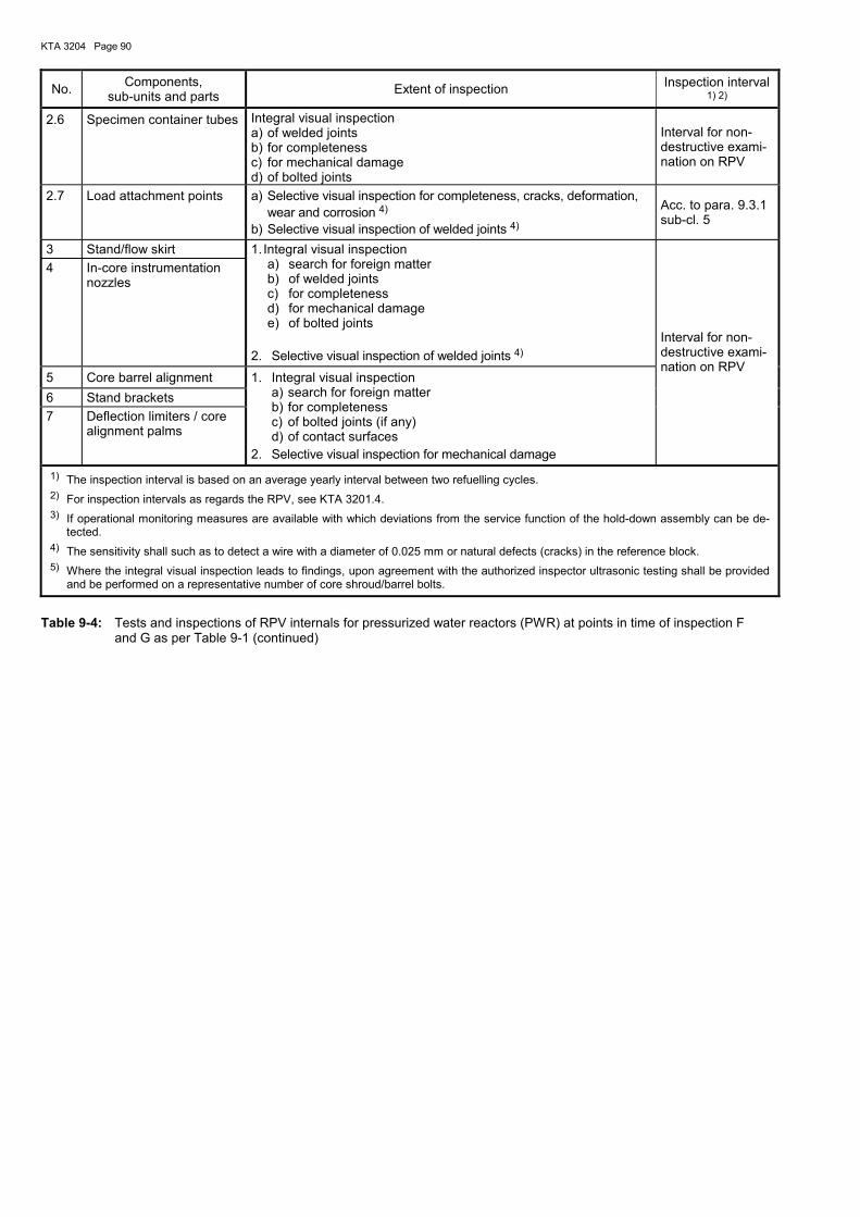
KTA 3204 Page 90
No. Components, sub-units and parts Extent of inspection Inspection interval
1) 2) 2.6 Specimen container tubes Integral visual inspection
a) of welded joints b) for completeness c) for mechanical damage d) of bolted joints
Interval for non-destructive exami-nation on RPV
2.7 Load attachment points a) Selective visual inspection for completeness, cracks, deformation, wear and corrosion 4)
b) Selective visual inspection of welded joints 4)
Acc. to para. 9.3.1 sub-cl. 5
3 Stand/flow skirt 4 In-core instrumentation
nozzles
1. Integral visual inspection a) search for foreign matter b) of welded joints c) for completeness d) for mechanical damage e) of bolted joints
2. Selective visual inspection of welded joints 4)
5 Core barrel alignment 6 Stand brackets 7 Deflection limiters / core
alignment palms
1. Integral visual inspection a) search for foreign matter b) for completeness c) of bolted joints (if any) d) of contact surfaces
2. Selective visual inspection for mechanical damage
Interval for non-destructive exami-nation on RPV
1) The inspection interval is based on an average yearly interval between two refuelling cycles. 2) For inspection intervals as regards the RPV, see KTA 3201.4. 3) If operational monitoring measures are available with which deviations from the service function of the hold-down assembly can be de-
tected. 4) The sensitivity shall such as to detect a wire with a diameter of 0.025 mm or natural defects (cracks) in the reference block. 5) Where the integral visual inspection leads to findings, upon agreement with the authorized inspector ultrasonic testing shall be provided
and be performed on a representative number of core shroud/barrel bolts.
Table 9-4: Tests and inspections of RPV internals for pressurized water reactors (PWR) at points in time of inspection F and G as per Table 9-1 (continued)
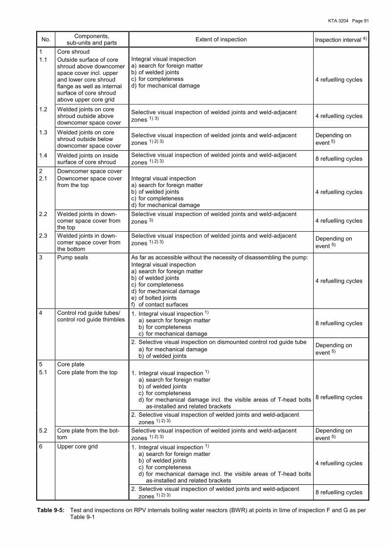
KTA 3204 Page 91
No. Components, sub-units and parts Extent of inspection Inspection interval 4)
1 Core shroud 1.1 Outside surface of core
shroud above downcomer space cover incl. upper and lower core shroud flange as well as internal surface of core shroud above upper core grid
Integral visual inspection a) search for foreign matter b) of welded joints c) for completeness d) for mechanical damage
4 refuelling cycles
1.2 Welded joints on core shroud outside above downcomer space cover
Selective visual inspection of welded joints and weld-adjacent zones 1) 3) 4 refuelling cycles
1.3 Welded joints on core shroud outside below downcomer space cover
Selective visual inspection of welded joints and weld-adjacent zones 1) 2) 3)
Depending on event 5)
1.4 Welded joints on inside surface of core shroud
Selective visual inspection of welded joints and weld-adjacent zones 1) 2) 3) 8 refuelling cycles
2 Downcomer space cover 2.1 Downcomer space cover
from the top Integral visual inspection a) search for foreign matter b) of welded joints c) for completeness d) for mechanical damage
4 refuelling cycles
2.2 Welded joints in down-comer space cover from the top
Selective visual inspection of welded joints and weld-adjacent zones 3) 4 refuelling cycles
2.3 Welded joints in down-comer space cover from the bottom
Selective visual inspection of welded joints and weld-adjacent zones 1) 2) 3)
Depending on event 5)
3 Pump seals
As far as accessible without the necessity of disassembling the pump: Integral visual inspection a) search for foreign matter b) of welded joints c) for completeness d) for mechanical damage e) of bolted joints f) of contact surfaces
4 refuelling cycles
1. Integral visual inspection 1) a) search for foreign matter b) for completeness c) for mechanical damage
8 refuelling cycles
4 Control rod guide tubes/ control rod guide thimbles
2. Selective visual inspection on dismounted control rod guide tube a) for mechanical damage b) of welded joints
Depending on event 5)
5 Core plate 1. Integral visual inspection 1)
a) search for foreign matter b) of welded joints c) for completeness d) for mechanical damage incl. the visible areas of T-head bolts
as-installed and related brackets
5.1 Core plate from the top
2. Selective visual inspection of welded joints and weld-adjacent zones 1) 2) 3)
8 refuelling cycles
5.2 Core plate from the bot-tom
Selective visual inspection of welded joints and weld-adjacent zones 1) 2) 3)
Depending on event 5)
1. Integral visual inspection 1) a) search for foreign matter b) of welded joints c) for completeness d) for mechanical damage incl. the visible areas of T-head bolts
as-installed and related brackets
4 refuelling cycles
6 Upper core grid
2. Selective visual inspection of welded joints and weld-adjacent zones 1) 2) 3)
8 refuelling cycles
Table 9-5: Test and inspections on RPV internals boiling water reactors (BWR) at points in time of inspection F and G as per Table 9-1
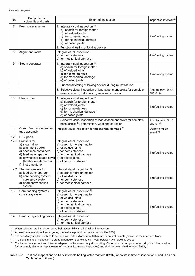
KTA 3204 Page 92
Nr. Components, sub-units and parts Extent of inspection Inspection interval 4)
1. Integral visual inspection 1) a) search for foreign matter b) of welded joints c) for completeness d) for mechanical damage e) of bolted joints
7 Feed water sparger
2. Functional testing of locking devices
4 refuelling cycles
8 Alignment tracks Integral visual inspection a) for completeness b) for mechanical damage
4 refuelling cycles
1. Integral visual inspection 1) a) search for foreign matter b) of welded joints c) for completeness d) for mechanical damage e) of bolted joints
2. Functional testing of locking devices during re-installation
4 refuelling cycles
9 Steam separator
3. Selective visual inspection of load attachment points for complete-ness, cracks 3), deformation, wear and corrosion
Acc. to para. 9.3.1 sub-cl. 5
1. Integral visual inspection 1) a) search for foreign matter b) of welded joints c) for completeness d) for mechanical damage e) of bolted joints
4 refuelling cycles
10 Steam dryer
2. Selective visual inspection of load attachment points for complete-ness, cracks 3), deformation, wear and corrosion
Acc. to para. 9.3.1 sub-cl. 5
11 Core flux measurement tube assembly
Integral visual inspection for mechanical damage 1) Depending on event 5)
12 RPV parts 12.1 Brackets for
a) steam dryer b) alignment tracks c) specimen containers d) feed water sparger e) downcomer space cover
(hold-down elements) f) instrumentation
Integral visual inspection a) search for foreign matter b) of welded joints c) for completeness d) for mechanical damage e) of bolted joints f) of contact surfaces
4 refuelling cycles
12.2 Thermal sleeves for a) feed water sparger b) core flooding system/
core spray system c) head spray cooling
system
Integral visual inspection 1) a) search for foreign matter b) of welded joints c) for completeness d) for mechanical damage
4 refuelling cycles
13 Core flooding system / core spray system
Integral visual inspection 1) a) search for foreign matter b) of welded joints c) for completeness d) for mechanical damage e) of bolted joints f) of contact surfaces
14 Head spray cooling device Integral visual inspection a) for completeness b) for mechanical damage
4 refuelling cycles
1) When selecting the inspection area, their accessibility shall be taken into account. 2) Accessible areas without endangering the test equipment ( no loose parts in the RPV). 3) The sensitivity shall be such as to detect a wire with a diameter of 0.025 mm or natural defects (cracks) in the reference block. 4) The point in time of inspection refers to a period of approximately 1 year between two refuelling cycles. 5) The inspections (extent and intervals) depend on the events (e.g. dismantling of internal axial pumps, control rod guide tubes or edge
fuel assembly elements, replacement of neutron flux measuring lances) and shall be determined for each facility.
Table 9-5: Test and inspections on RPV internals boiling water reactors (BWR) at points in time of inspection F and G as per Table 9-1 (continued)
KTA 3204 Page 93
Annex W
Materials
Page Annex W 1 Austenitic stainless steels .................................................................................................94 Annex W 2 Nickel alloys.....................................................................................................................104 Annex W 3 Austenitic stainless precision casting ..............................................................................114 Annex W 4 Filler metals, brazing alloy and flux for thermal spraying.................................................117 Annex W 5 Machine elements ...........................................................................................................123 Annex W 6 Special materials .............................................................................................................129
KTA 3204 Page 94
Annex W 1
Austenitic stainless steels
Contents: W 1.1 Scope W 1.2 Materials W 1.3 Nondestructive examinations W 1.4 Specimen-taking locations and specimen orientation W 1.5 Materials test sheets W 1.5.1 Plate, sheet and strip of quality classes AS-RE 1 and
AS-RE 2 as well as AS-RE 3 inside the RPV W 1.5.2 Forgings, forged rings, bars and sections of quality
classes AS-RE 1 and AS-RE 2 as well as AS-RE 3 inside the RPV
W 1.5.3 Welded and seamless tubes of quality classes AS-RE 1 and AS-RE 2 as well as AS-RE 3 inside the RPV
W 1.5.4 Plate, sheet and strip of quality class AS-RE 3 out-side the RPV
W 1.5.5 Forgings, bars and sections of quality class AS-RE 3 outside the RPV
W 1.5.6 Welded and seamless tubes of quality class AS-RE 3 outside the RPV
W 1.1 Scope
This annex lays down the requirements regarding quality characteristics, type and extent of tests and examinations as well as the type of certificates for austenitic stainless steels. The requirements shall apply for the quenched or stabilised condition unless specified otherwise hereinafter.
W 1.2 Materials
W 1.2.1 Materials for quality class AS-RE 3 outside the RPV
All materials meeting the quality requirements to DIN EN 10088-2, DIN EN 10088-3, DIN EN 10216-5, DIN EN 10217-7, DIN EN 10222-5, DIN EN 10028-7, DIN EN 10250-4 and DIN EN 10272 are allowable. The tests and examinations to be per-formed, the extent of testing and the attestation of quality characteristics shall be taken from the materials test sheets (WPB) W 1.5.4 to W 1.5.6.
W 1.2.2 Materials for quality classes AS-RE 1 and AS-RE 2 as well as for parts of quality class AS-RE 3 inside the RPV
W 1.2.2.1 General requirements
(1) Materials no. 1.4306, 1.4541, 1.4550, 1.4571 and 1.4580 to DIN EN 10222-5, DIN EN 10216-5, DIN EN 10217-7, DIN EN 10028-7 or DIN EN 10272 with restricted chemical composition and mechanical properties in accordance with Sections W 1.2.2.2 to W 1.2.2.9 may be used.
(2) For parts inside the RPV of boiling-water reactors, which are subject to welding work (except for single-layer lock welds, the material no. 1.4450 shall be used.
(3) The requirements to be met by the manufacturers of the various product forms are laid down in clause 7.2.1.
(4) The tests and examinations as well as the certificates required are given in the materials test sheets (WPB) in Sec-tions W 1.5.1 to W 1.5.3.
W 1.2.2.2 Steel-making process
The steel-making process is left to the manufacturer unless agreed otherwise in the order. Upon request, it shall, however, be made known to the purchaser.
W 1.2.2.3 Chemical composition
The materials shall only be used with the chemical composi-tion to Table W 1-1, which is restricted compared to the stan-dard composition to the standards mentioned in Section W 1.2.2.1.
W 1.2.2.4 Heat treatment
Deviating from and in addition to the requirements of the standards mentioned in W 1.2.2.1 a) solution annealing shall be performed in any case, b) a temperature of 1100 °C shall be the upper limit for solu-
tion annealing, c) upon solution annealing cooling shall be effected at a
sufficiently rapid cooling rate to exclude carbide precipita-tions.
W 1.2.2.5 Mechanical properties
The stipulations of the standards mentioned in Section W 1.2.2.1 apply. Deviating from this requirement for the material with the mate-rial no. 1.4550 the requirements of Table W 1-2 and W 1-3 apply. For forgings, bars and rings with a heat treated wall thickness not covered by DIN EN 10222-5 and DIN EN 10272 the stipu-lations of the material certification apply.
W 1.2.2.6 Physical characteristics
Typical values for the physical characteristics are specified in Table A3 of DIN EN 10088-1 and in Table W 1-4.
W 1.2.2.7 Delta-ferrite content
The base material of parts which, in the course of further fabrication, will be subjected to welding, shall show a delta-ferrite content in the weld zone of between 2 and 10 %. A continuous ferritic structure is not allowed in either case.
W 1.2.2.8 Evaluation of microstructure and determination of grain size
(1) The average grain size shall be determined and corre-spond to a characteristic index equal to or greater than 4 in accordance with DIN EN ISO 643. Deviations are allowed provided requirements regarding ultrasonic examinations to Section 7.3.5.6.4 are not obstructed in any way.
(2) Structural constituents of the σ-phase that can be de-termined by metallography are not permitted.
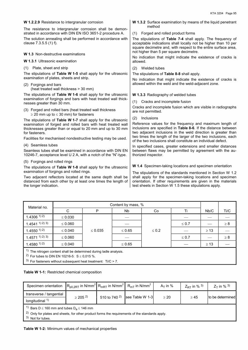
KTA 3204 Page 95
W 1.2.2.9 Resistance to intergranular corrosion
The resistance to intergranular corrosion shall be demon-strated in accordance with DIN EN ISO 3651-2 procedure A. The solution annealing shall be performed in accordance with clause 7.3.5.5 (1) f).
W 1.3 Non-destructive examinations
W 1.3.1 Ultrasonic examination
(1) Plate, sheet and strip The stipulations of Table W 1-5 shall apply for the ultrasonic examination of plates, sheets and strip.
(2) Forgings and bars (heat treated wall thickness > 30 mm)
The stipulations of Table W 1-6 shall apply for the ultrasonic examination of forgings and bars with heat treated wall thick-nesses greater than 30 mm.
(3) Forged and rolled bars (heat treated wall thickness ≥ 20 mm up to ≤ 30 mm) for fasteners
The stipulations of Table W 1-7 shall apply for the ultrasonic examination of forged and rolled bars with heat treated wall thicknesses greater than or equal to 20 mm and up to 30 mm for fasteners. Facilities for mechanised nondestructive testing may be used.
(4) Seamless tubes Seamless tubes shall be examined in accordance with DIN EN 10246-7, acceptance level U 2 A, with a notch of the �N�-type.
(5) Forgings and rolled rings The stipulations of Table W 1-8 shall apply for the ultrasonic examination of forgings and rolled rings. Two adjacent reflectors located at the same depth shall be distanced from each other by at least one times the length of the longer indication.
W 1.3.2 Surface examination by means of the liquid penetrant method
(1) Forged and rolled product forms The stipulations of Table 7-4 shall apply. The frequency of acceptable indications shall locally not be higher than 10 per square decimetre and, with respect to the entire surface area, not higher than 5 per square decimetre. No indication that might indicate the existence of cracks is allowed.
(2) Welded tubes The stipulations of Table 8-8 shall apply. No indication that might indicate the existence of cracks is allowed within the weld and the weld-adjacent zone.
W 1.3.3 Radiography of welded tubes
(1) Cracks and incomplete fusion Cracks and incomplete fusion which are visible in radiographs are not permitted.
(2) Inclusions Reference values for the frequency and maximum length of inclusions are specified in Table 8-6. If the distance between two adjacent inclusions in the weld direction is greater than two times the length of the larger of the two inclusions, each of the two inclusions shall constitute an individual defect. In specified cases, greater extensions and smaller distances between flaws may be permitted by agreement with the au-thorized inspector.
W 1.4 Specimen-taking locations and specimen orientation
The stipulations of the standards mentioned in Section W 1.2 shall apply for the specimen-taking locations and specimen orientation. If other requirements are given in the materials test sheets in Section W 1.5 these stipulations apply.
Content by mass, %
Material no. C P Nb Co Ti Nb/C Ti/C
1.4306 1) 2) ≤ 0.030
1.4541 1) 2) 3) ≤ 0.060 ≤ 0.7 ≥ 8
1.4550 1) 2) ≤ 0.040 ≤ 0.65 ≥ 13
1.4571 1) 2) 3) ≤ 0.060 ≤ 0.7 ≥ 8
1.4580 1) 2) ≤ 0.040
≤ 0.035
≤ 0.65
≤ 0.2
≥ 13 1) The nitrogen content shall be determined during ladle analysis. 2) For tubes to DIN EN 10216-5: S ≤ 0,015 %. 3) For fasteners without subsequent heat treatment: Ti/C > 7.
Table W 1-1: Restricted chemical composition
Specimen orientation Rp0,2RT in N/mm2 RmRT in N/mm2 RmT in N/mm2 AT in % ZRT in % 3) ZT in % 3)
transverse / tangential
longitudinal 1) ≥ 205 2) 510 to 740 2) see Table W 1-3 ≥ 20 ≥ 45 to be determined
1) Bars D ≤ 160 mm and tubes Da ≤ 146 mm 2) Only for plates and sheets, for other product forms the requirements of the standards apply. 3) Not for tubes.
Table W 1-2: Minimum values of mechanical properties
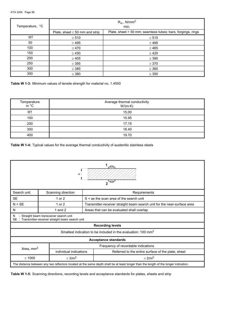
KTA 3204 Page 96
Temperature, °C
Rm , N/mm2 min.
Plate, sheet ≤ 50 mm and strip Plate, sheet > 50 mm; seamless tubes; bars, forgings, rings RT ≥ 510 ≥ 510 50 ≥ 495 ≥ 495 100 ≥ 470 ≥ 465 150 ≥ 430 ≥ 420 200 ≥ 405 ≥ 390 250 ≥ 395 ≥ 370 300 ≥ 385 ≥ 360 350 ≥ 380 ≥ 350
Table W 1-3: Minimum values of tensile strength for material no. 1.4550
Temperature
in °C Average thermal conductivity
W/(m⋅K)
RT 15,00
100 15.95
200 17.15
300 18.40
400 19.70
Table W 1-4: Typical values for the average thermal conductivity of austenitic stainless steels
2
1
s
Search unit Scanning direction Requirements
SE 1 or 2 S < as the scan area of the search unit
N + SE 1 or 2 Transmitter-receiver straight beam search unit for the near-surface area
N 1 and 2 Areas that can be evaluated shall overlap
N : Straight beam transceiver search unit SE : Transmitter-receiver straight beam search unit
Recording levels
Smallest indication to be included in the evaluation: 100 mm2
Acceptance standards
Frequency of recordable indications Area, mm2
individual indications Referred to the entire surface of the plate, sheet
≤ 1000 ≤ 3/m2 ≤ 2/m2
The distance between any two reflectors located at the same depth shall be at least longer than the length of the longer indication.
Table W 1-5: Scanning directions, recording levels and acceptance standards for plates, sheets and strip
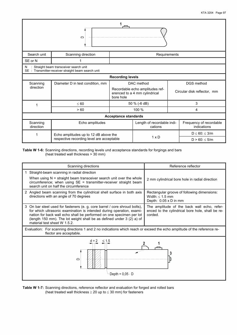
KTA 3204 Page 97
1
D
Search unit Scanning direction Requirements
SE or N 1
N : Straight beam transceiver search unit SE : Transmitter-receiver straight beam search unit
Recording levels
Scanning direction
Diameter D in test condition, mm DAC method Recordable echo amplitudes ref-erenced to a 4 mm cylindrical bore hole
DGS method
Circular disk reflector, mm
≤ 60 50 % (-6 dB) 3 1 > 60 100 % 4
Acceptance standards
Scanning direction
Echo amplitudes Length of recordable indi-cations
Frequency of recordable indications
D ≤ 60: ≤ 3/m 1 Echo amplitudes up to 12 dB above the respective recording level are acceptable
1 x D
D > 60: ≤ 5/m
Table W 1-6: Scanning directions, recording levels und acceptance standards for forgings and bars (heat treated wall thickness > 30 mm)
Scanning directions Reference reflector
1 Straight-beam scanning in radial direction When using N = straight beam transceiver search unit over the whole
circumference; when using SE = transmitter-receiver straight beam search unit on half the circumference
2 mm cylindrical bore hole in radial direction
2 Angled beam scanning from the cylindrical shell surface in both axis directions with an angle of 70 degrees
Rectangular groove of following dimensions: Width: ≤ 1.5 mm Depth: 0.05 x D in mm
3 On bar steel used for fasteners (e. g. core barrel / core shroud bolts), for which ultrasonic examination is intended during operation, exami-nation for back wall echo shall be performed on one specimen per lot (length 150 mm). The lot weight shall be as defined under 3 (2) a) of material test sheet W 1.5.2.
The amplitude of the back wall echo, refer-enced to the cylindrical bore hole, shall be re-corded.
Evaluation: For scanning directions 1 and 2 no indications which reach or exceed the echo amplitude of the reference re-flector are acceptable.
2 1
3
D
d = 2 ≤ 1.5
Depth = 0,05 D⋅
Table W 1-7: Scanning directions, reference reflector and evaluation for forged and rolled bars (heat treated wall thickness ≥ 20 up to ≤ 30 mm) for fasteners
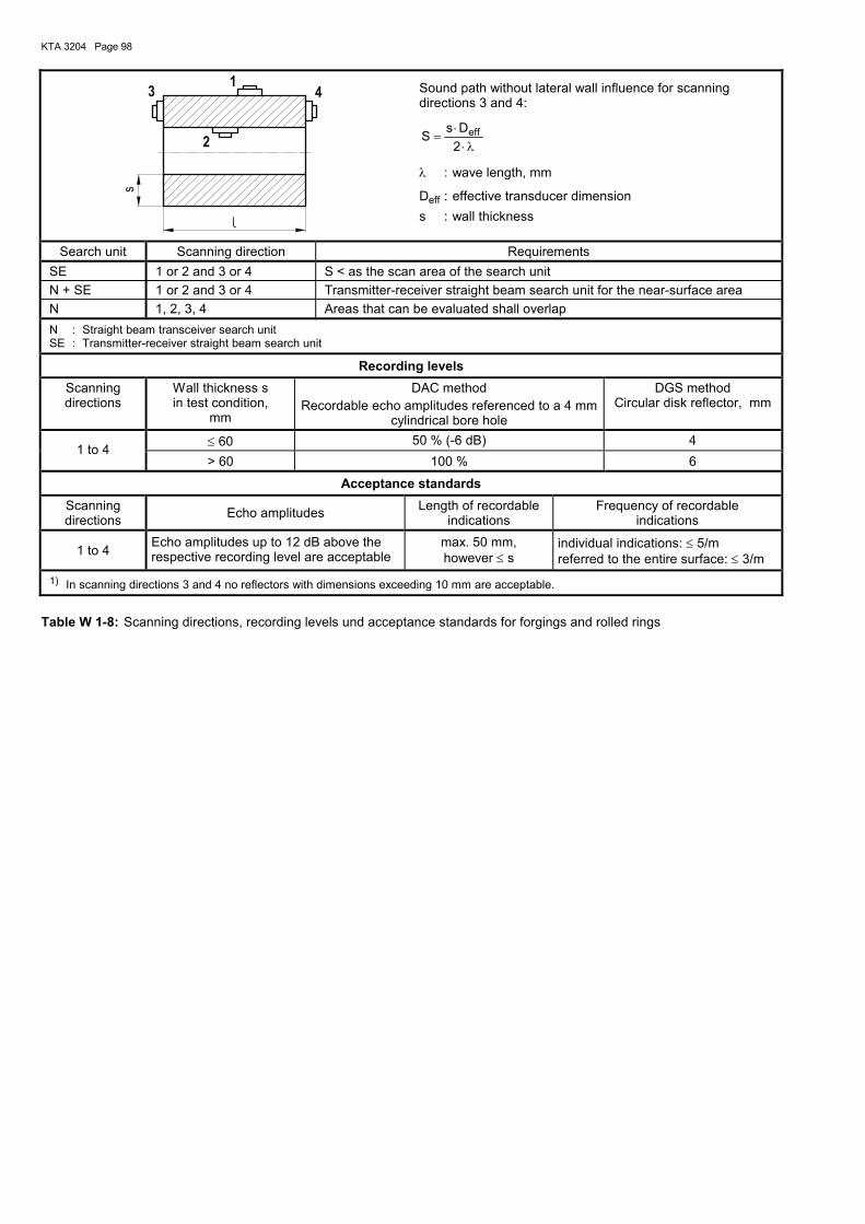
KTA 3204 Page 98
43
2
1
s
Sound path without lateral wall influence for scanning directions 3 and 4:
λ⋅⋅
=2DsS eff
λ : wave length, mm
Deff : effective transducer dimension s : wall thickness
Search unit Scanning direction Requirements SE 1 or 2 and 3 or 4 S < as the scan area of the search unit N + SE 1 or 2 and 3 or 4 Transmitter-receiver straight beam search unit for the near-surface area N 1, 2, 3, 4 Areas that can be evaluated shall overlap N : Straight beam transceiver search unit SE : Transmitter-receiver straight beam search unit
Recording levels
Scanning directions
Wall thickness s in test condition,
mm
DAC method Recordable echo amplitudes referenced to a 4 mm
cylindrical bore hole
DGS method Circular disk reflector, mm
≤ 60 50 % (-6 dB) 4 1 to 4
> 60 100 % 6
Acceptance standards
Scanning directions Echo amplitudes Length of recordable
indications Frequency of recordable
indications
1 to 4 Echo amplitudes up to 12 dB above the respective recording level are acceptable
max. 50 mm, however ≤ s
individual indications: ≤ 5/m referred to the entire surface: ≤ 3/m
1) In scanning directions 3 and 4 no reflectors with dimensions exceeding 10 mm are acceptable.
Table W 1-8: Scanning directions, recording levels und acceptance standards for forgings and rolled rings
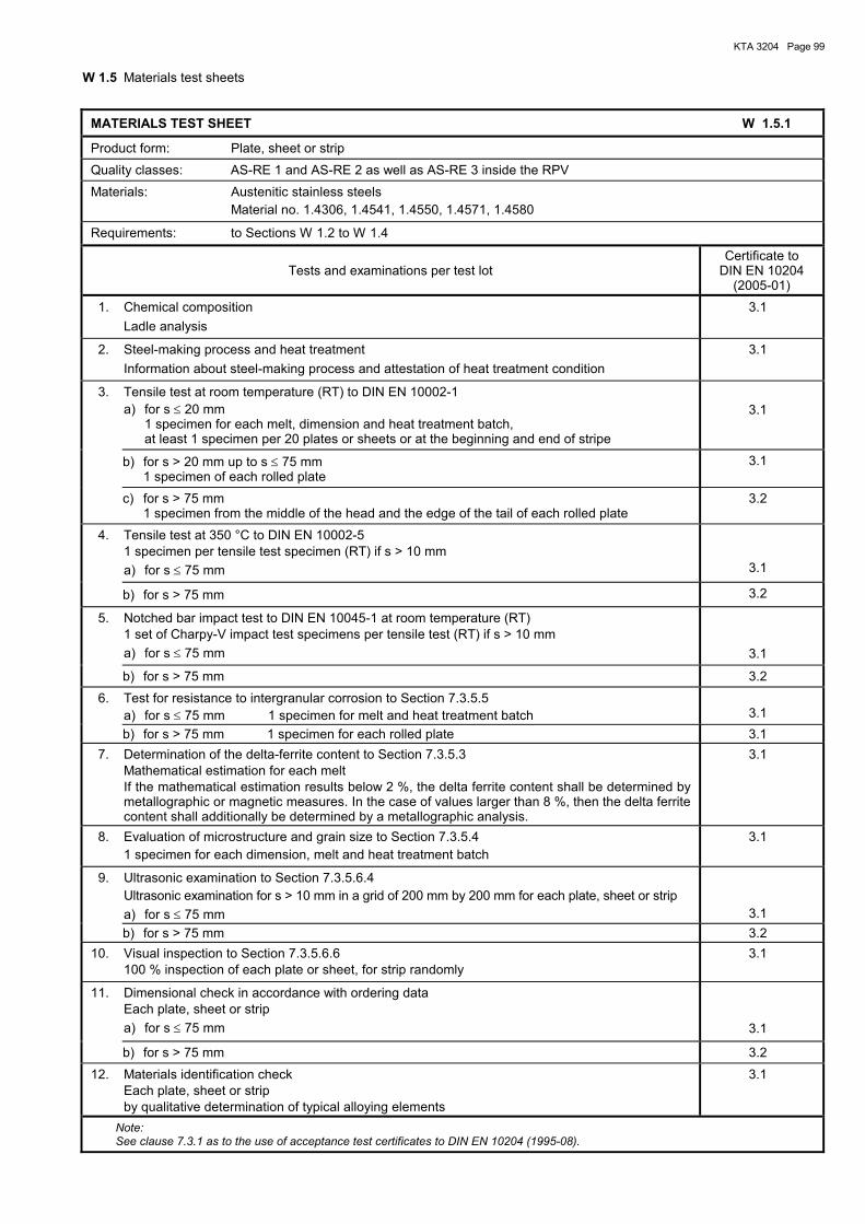
KTA 3204 Page 99
W 1.5 Materials test sheets
MATERIALS TEST SHEET W 1.5.1
Product form: Plate, sheet or strip Quality classes: AS-RE 1 and AS-RE 2 as well as AS-RE 3 inside the RPV Materials: Austenitic stainless steels Material no. 1.4306, 1.4541, 1.4550, 1.4571, 1.4580
Requirements: to Sections W 1.2 to W 1.4
Tests and examinations per test lot Certificate to
DIN EN 10204 (2005-01)
1. Chemical composition Ladle analysis
3.1
2. Steel-making process and heat treatment Information about steel-making process and attestation of heat treatment condition
3.1
3. Tensile test at room temperature (RT) to DIN EN 10002-1 a) for s ≤ 20 mm 1 specimen for each melt, dimension and heat treatment batch, at least 1 specimen per 20 plates or sheets or at the beginning and end of stripe
3.1
b) for s > 20 mm up to s ≤ 75 mm 1 specimen of each rolled plate
3.1
c) for s > 75 mm 1 specimen from the middle of the head and the edge of the tail of each rolled plate
3.2
4. Tensile test at 350 °C to DIN EN 10002-5 1 specimen per tensile test specimen (RT) if s > 10 mm
a) for s ≤ 75 mm
3.1
b) for s > 75 mm 3.2
5. Notched bar impact test to DIN EN 10045-1 at room temperature (RT) 1 set of Charpy-V impact test specimens per tensile test (RT) if s > 10 mm
a) for s ≤ 75 mm
3.1
b) for s > 75 mm 3.2
6. Test for resistance to intergranular corrosion to Section 7.3.5.5 a) for s ≤ 75 mm 1 specimen for melt and heat treatment batch
3.1
b) for s > 75 mm 1 specimen for each rolled plate 3.1 7. Determination of the delta-ferrite content to Section 7.3.5.3 Mathematical estimation for each melt If the mathematical estimation results below 2 %, the delta ferrite content shall be determined by
metallographic or magnetic measures. In the case of values larger than 8 %, then the delta ferrite content shall additionally be determined by a metallographic analysis.
3.1
8. Evaluation of microstructure and grain size to Section 7.3.5.4 1 specimen for each dimension, melt and heat treatment batch
3.1
9. Ultrasonic examination to Section 7.3.5.6.4 Ultrasonic examination for s > 10 mm in a grid of 200 mm by 200 mm for each plate, sheet or strip a) for s ≤ 75 mm
3.1 b) for s > 75 mm 3.2 10. Visual inspection to Section 7.3.5.6.6 100 % inspection of each plate or sheet, for strip randomly
3.1
11. Dimensional check in accordance with ordering data Each plate, sheet or strip a) for s ≤ 75 mm
3.1
b) for s > 75 mm 3.2
12. Materials identification check Each plate, sheet or strip by qualitative determination of typical alloying elements
3.1
Note: See clause 7.3.1 as to the use of acceptance test certificates to DIN EN 10204 (1995-08).
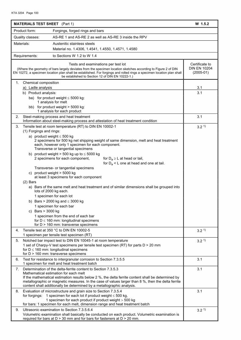
KTA 3204 Page 100
MATERIALS TEST SHEET (Part 1) W 1.5.2
Product form: Forgings, forged rings and bars
Quality classes: AS-RE 1 and AS-RE 2 as well as AS-RE 3 inside the RPV
Materials: Austenitic stainless steels Material no. 1.4306, 1.4541, 1.4550, 1.4571, 1.4580
Requirements: to Sections W 1.2 to W 1.4
Tests and examinations per test lot (Where the geometry of bars largely deviates from the specimen location sketches according to Figure 2 of DIN
EN 10272, a specimen location plan shall be established. For forgings and rolled rings a specimen location plan shall be established to Section 12 of DIN EN 10222-1.)
Certificate to DIN EN 10204
(2005-01)
1. Chemical composition a) Ladle analysis 3.1 b) Product analysis: 3.1 ba) for product weight ≤ 5000 kg: 1 analysis for melt
bb) for product weight > 5000 kg: 1 analysis for each product
2. Steel-making process and heat treatment 3.1 Information about steel-making process and attestation of heat treatment condition 3. Tensile test at room temperature (RT) to DIN EN 10002-1 3.2 1) (1) Forgings and rings: a) product weight ≤ 500 kg 2 specimens for 500 kg net shipping weight of same dimension, melt and heat treatment
each, however only 1 specimen for each component. Transverse or tangential specimens
b) product weight > 500 kg up to ≤ 5000 kg 2 specimens for each component, for Da ≥ L at head or tail,
for Da < L one at head and one at tail. Transverse- or tangential specimens
c) product weight > 5000 kg at least 3 specimens for each component
(2) Bars a) Bars of the same melt and heat treatment and of similar dimensions shall be grouped into
lots of 2000 kg each. 1 specimen for each lot
b) Bars > 2000 kg and ≤ 3000 kg 1 specimen for each bar
c) Bars > 3000 kg 1 specimen from the end of each bar for D ≤ 160 mm: longitudinal specimens for D > 160 mm: transverse specimens
4. Tensile test at 350 °C to DIN EN 10002-5 3.2 1) 1 specimen per tensile test specimen (RT) 5. Notched bar impact test to DIN EN 10045-1 at room temperature 3.2 1) 1 set of Charpy-V test specimens per tensile test specimen (RT) for parts D > 20 mm for D ≤ 160 mm: longitudinal specimens for D > 160 mm: transverse specimens
6. Test for resistance to intergranular corrosion to Section 7.3.5.5 3.1 1 specimen for melt and heat treatment batch 7. Determination of the delta-ferrite content to Section 7.3.5.3 3.1 Mathematical estimation for each melt If the mathematical estimation results below 2 %, the delta ferrite content shall be determined by
metallographic or magnetic measures. In the case of values larger than 8 %, then the delta ferrite content shall additionally be determined by a metallographic analysis.
8. Evaluation of microstructure and grain size to Section 7.3.5.4 3.1 for forgings: 1 specimen for each lot if product weight ≤ 500 kg,
1 specimen for each product if product weight > 500 kg for bars: 1 specimen for each melt, dimension range and heat treatment batch
9. Ultrasonic examination to Section 7.3.5.6.4 3.2 1) Volumetric examination shall basically be conducted on each product. Volumetric examination is
required for bars at D > 30 mm and for bars for fasteners at D > 20 mm.
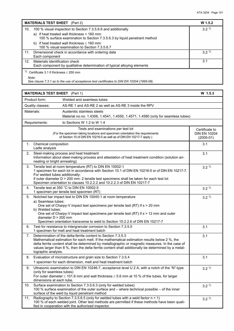
KTA 3204 Page 101
MATERIALS TEST SHEET (Part 2) W 1.5.2
10. 100 % visual inspection to Section 7.3.5.6.6 and additionally 3.2 1) a) if heat treated wall thickness > 160 mm: 100 % surface examination to Section 7.3.5.6.3 by liquid penetrant method b) if heat treated wall thickness ≤ 160 mm: 100 % visual examination to Section 7.3.5.6.7
11. Dimensional check in accordance with ordering data 3.2 1) Each component 12. Materials identification check 3.1 Each component by qualitative determination of typical alloying elements 1) Certificate 3.1 if thickness ≤ 250 mm
Note: See clause 7.3.1 as to the use of acceptance test certificates to DIN EN 10204 (1995-08).
MATERIALS TEST SHEET (Part 1) W 1.5.3
Product form: Welded and seamless tubes Quality classes: AS-RE 1 and AS-RE 2 as well as AS-RE 3 inside the RPV Materials: Austenitic stainless steels Material no.no. 1.4306, 1.4541, 1.4550, 1.4571, 1.4580 (only for seamless tubes)
Requirements: to Sections W 1.2 to W 1.4
Tests and examinations per test lot (For the specimen taking locations and specimen orientation the requirements
of Section 10 of DIN EN 10216-5 as well as of DIN EN 10217-7 apply.)
Certificate to DIN EN 10204
(2005-01)
1. Chemical composition Ladle analysis
3.1
2. Steel-making process and heat treatment Information about steel-making process and attestation of heat treatment condition (solution an-
nealing or bright annealing)
3.1
3. Tensile test at room temperature (RT) to DIN EN 10002-1 1 specimen for each lot in accordance with Section 10.1 of DIN EN 10216-5 or of DIN EN 10217-7. For welded tubes additionally: if outer diameter D > 200 mm: 2 tensile test specimens shall be taken for each test lot Specimen orientation to clauses 10.2.2.2 and 10.2.2.3 of DIN EN 10217-7
3.2 1)
4. Tensile test at 350 °C to DIN EN 10002-5 1 specimen per tensile test specimen (RT)
3.2 1)
5. Notched bar impact test to DIN EN 10045-1 at room temperature a) Seamless tubes: One set of Charpy-V impact test specimens per tensile test (RT) if s > 20 mm
3.2 1)
b) Welded tubes: One set of Charpy-V impact test specimens per tensile test (RT) if s > 12 mm and outer
diameter D > 200 mm Specimen orientation transverse to weld to Section 10.2.2.6 of DIN EN 10217-7
6. Test for resistance to intergranular corrosion to Section 7.3.5.5 1 specimen for melt and heat treatment batch
3.1
7. Determination of the delta-ferrite content to Section 7.3.5.3 Mathematical estimation for each melt. If the mathematical estimation results below 2 %, the
delta ferrite content shall be determined by metallographic or magnetic measures. In the case of values larger than 8 %, then the delta ferrite content shall additionally be determined by a metal-lographic analysis.
3.1
8. Evaluation of microstructure and grain size to Section 7.3.5.4 1 specimen for each dimension, melt and heat treatment batch
3.1
9. Ultrasonic examination to DIN EN 10246-7, acceptance level U 2 A, with a notch of the �N�-type (only for seamless tubes)
For outer diameter ≤ 101.6 mm and wall thickness ≤ 5.6 mm at 10 % of the tubes, for larger dimensions at each tube.
3.2 1)
10. Surface examination to Section 7.3.5.6.3 (only for welded tubes) 100 % surface examination of the outer surface and � where technical possible � of the inner
surface of the weld by liquid penetrant method
3.2 1)
11. Radiography to Section 7.3.5.6.5 (only for welded tubes with a weld factor n = 1) 100 % of each welded joint. Other test methods are permitted if these methods have been quali-fied in cooperation with the authorized inspector.
3.2 1)
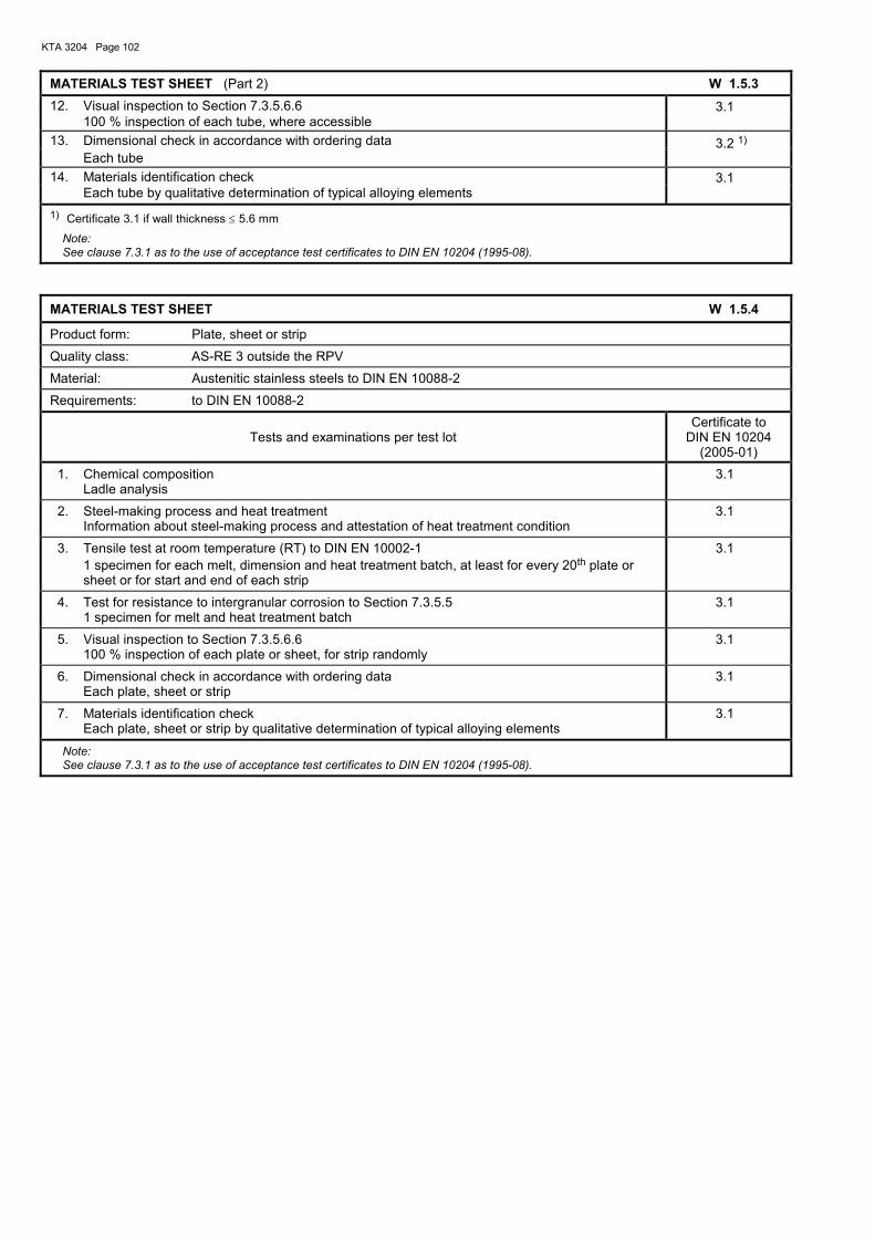
KTA 3204 Page 102
MATERIALS TEST SHEET (Part 2) W 1.5.3 12. Visual inspection to Section 7.3.5.6.6 3.1 100 % inspection of each tube, where accessible 13. Dimensional check in accordance with ordering data Each tube
3.2 1)
14. Materials identification check 3.1 Each tube by qualitative determination of typical alloying elements 1) Certificate 3.1 if wall thickness ≤ 5.6 mm
Note: See clause 7.3.1 as to the use of acceptance test certificates to DIN EN 10204 (1995-08).
MATERIALS TEST SHEET W 1.5.4
Product form: Plate, sheet or strip Quality class: AS-RE 3 outside the RPV Material: Austenitic stainless steels to DIN EN 10088-2
Requirements: to DIN EN 10088-2
Tests and examinations per test lot Certificate to
DIN EN 10204 (2005-01)
1. Chemical composition Ladle analysis
3.1
2. Steel-making process and heat treatment Information about steel-making process and attestation of heat treatment condition
3.1
3. Tensile test at room temperature (RT) to DIN EN 10002-1 1 specimen for each melt, dimension and heat treatment batch, at least for every 20th plate or
sheet or for start and end of each strip
3.1
4. Test for resistance to intergranular corrosion to Section 7.3.5.5 1 specimen for melt and heat treatment batch
3.1
5. Visual inspection to Section 7.3.5.6.6 100 % inspection of each plate or sheet, for strip randomly
3.1
6. Dimensional check in accordance with ordering data Each plate, sheet or strip
3.1
7. Materials identification check Each plate, sheet or strip by qualitative determination of typical alloying elements
3.1
Note: See clause 7.3.1 as to the use of acceptance test certificates to DIN EN 10204 (1995-08).
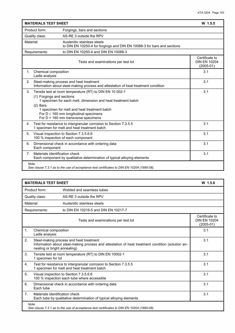
KTA 3204 Page 103
MATERIALS TEST SHEET W 1.5.5
Product form: Forgings, bars and sections Quality class: AS-RE 3 outside the RPV Material: Austenitic stainless steels to DIN EN 10250-4 for forgings and DIN EN 10088-3 for bars and sections
Requirements: to DIN EN 10250-4 and DIN EN 10088-3
Tests and examinations per test lot Certificate to
DIN EN 10204 (2005-01)
1. Chemical composition Ladle analysis
3.1
2. Steel-making process and heat treatment Information about steel-making process and attestation of heat treatment condition
3.1
3. Tensile test at room temperature (RT) to DIN EN 10 002-1 (1) Forgings and sections 1 specimen for each melt, dimension and heat treatment batch (2) Bars 1 specimen for melt and heat treatment batch For D ≤ 160 mm longitudinal specimens For D > 160 mm transverse specimens
3.1
4. Test for resistance to intergranular corrosion to Section 7.3.5.5 1 specimen for melt and heat treatment batch
3.1
5. Visual inspection to Section 7.3.5.6.6 100 % inspection of each component
3.1
6. Dimensional check in accordance with ordering data Each component
3.1
7. Materials identification check Each component by qualitative determination of typical alloying elements
3.1
Note: See clause 7.3.1 as to the use of acceptance test certificates to DIN EN 10204 (1995-08).
MATERIALS TEST SHEET W 1.5.6
Product form: Welded and seamless tubes
Quality class: AS-RE 3 outside the RPV
Material: Austenitic stainless steels
Requirements: to DIN EN 10216-5 and DIN EN 10217-7
Tests and examinations per test lot Certificate to
DIN EN 10204 (2005-01)
1. Chemical composition Ladle analysis
3.1
2. Steel-making process and heat treatment Information about steel-making process and attestation of heat treatment condition (solution an-
nealing or bright annealing)
3.1
3. Tensile test at room temperature (RT) to DIN EN 10002-1 1 specimen for lot
3.1
4. Test for resistance to intergranular corrosion to Section 7.3.5.5 1 specimen for melt and heat treatment batch
3.1
5. Visual inspection to Section 7.3.5.6.6 100 % inspection each tube where accessible
3.1
6. Dimensional check in accordance with ordering data Each tube
3.1
7. Materials identification check Each tube by qualitative determination of typical alloying elements
3.1
Note: See clause 7.3.1 as to the use of acceptance test certificates to DIN EN 10204 (1995-08).
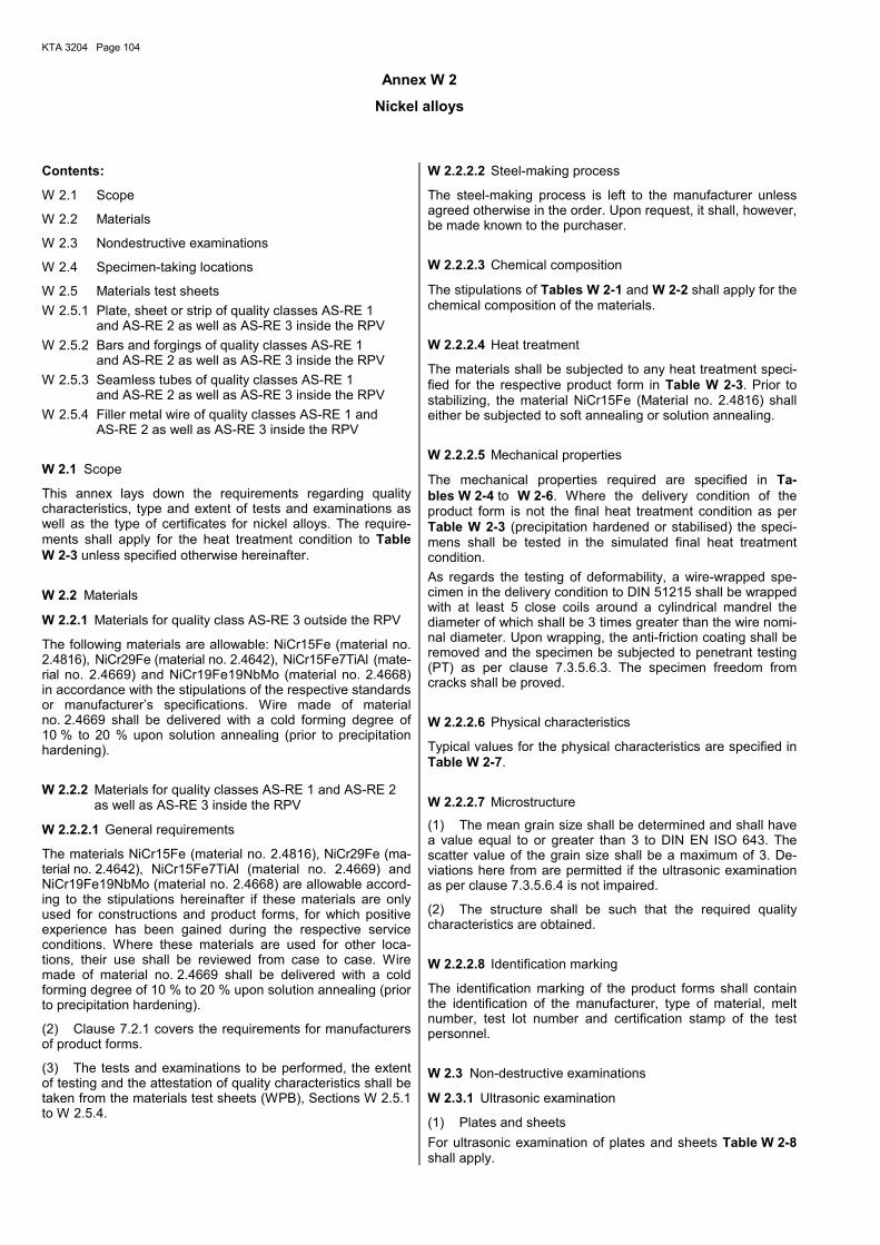
KTA 3204 Page 104
Annex W 2
Nickel alloys
Contents:
W 2.1 Scope
W 2.2 Materials
W 2.3 Nondestructive examinations
W 2.4 Specimen-taking locations
W 2.5 Materials test sheets W 2.5.1 Plate, sheet or strip of quality classes AS-RE 1
and AS-RE 2 as well as AS-RE 3 inside the RPV W 2.5.2 Bars and forgings of quality classes AS-RE 1
and AS-RE 2 as well as AS-RE 3 inside the RPV W 2.5.3 Seamless tubes of quality classes AS-RE 1
and AS-RE 2 as well as AS-RE 3 inside the RPV W 2.5.4 Filler metal wire of quality classes AS-RE 1 and
AS-RE 2 as well as AS-RE 3 inside the RPV
W 2.1 Scope
This annex lays down the requirements regarding quality characteristics, type and extent of tests and examinations as well as the type of certificates for nickel alloys. The require-ments shall apply for the heat treatment condition to Table W 2-3 unless specified otherwise hereinafter.
W 2.2 Materials
W 2.2.1 Materials for quality class AS-RE 3 outside the RPV
The following materials are allowable: NiCr15Fe (material no. 2.4816), NiCr29Fe (material no. 2.4642), NiCr15Fe7TiAl (mate-rial no. 2.4669) and NiCr19Fe19NbMo (material no. 2.4668) in accordance with the stipulations of the respective standards or manufacturer�s specifications. Wire made of material no. 2.4669 shall be delivered with a cold forming degree of 10 % to 20 % upon solution annealing (prior to precipitation hardening).
W 2.2.2 Materials for quality classes AS-RE 1 and AS-RE 2 as well as AS-RE 3 inside the RPV
W 2.2.2.1 General requirements
The materials NiCr15Fe (material no. 2.4816), NiCr29Fe (ma-terial no. 2.4642), NiCr15Fe7TiAl (material no. 2.4669) and NiCr19Fe19NbMo (material no. 2.4668) are allowable accord-ing to the stipulations hereinafter if these materials are only used for constructions and product forms, for which positive experience has been gained during the respective service conditions. Where these materials are used for other loca-tions, their use shall be reviewed from case to case. Wire made of material no. 2.4669 shall be delivered with a cold forming degree of 10 % to 20 % upon solution annealing (prior to precipitation hardening).
(2) Clause 7.2.1 covers the requirements for manufacturers of product forms.
(3) The tests and examinations to be performed, the extent of testing and the attestation of quality characteristics shall be taken from the materials test sheets (WPB), Sections W 2.5.1 to W 2.5.4.
W 2.2.2.2 Steel-making process
The steel-making process is left to the manufacturer unless agreed otherwise in the order. Upon request, it shall, however, be made known to the purchaser.
W 2.2.2.3 Chemical composition
The stipulations of Tables W 2-1 and W 2-2 shall apply for the chemical composition of the materials.
W 2.2.2.4 Heat treatment
The materials shall be subjected to any heat treatment speci-fied for the respective product form in Table W 2-3. Prior to stabilizing, the material NiCr15Fe (Material no. 2.4816) shall either be subjected to soft annealing or solution annealing.
W 2.2.2.5 Mechanical properties
The mechanical properties required are specified in Ta-bles W 2-4 to W 2-6. Where the delivery condition of the product form is not the final heat treatment condition as per Table W 2-3 (precipitation hardened or stabilised) the speci-mens shall be tested in the simulated final heat treatment condition. As regards the testing of deformability, a wire-wrapped spe-cimen in the delivery condition to DIN 51215 shall be wrapped with at least 5 close coils around a cylindrical mandrel the diameter of which shall be 3 times greater than the wire nomi-nal diameter. Upon wrapping, the anti-friction coating shall be removed and the specimen be subjected to penetrant testing (PT) as per clause 7.3.5.6.3. The specimen freedom from cracks shall be proved.
W 2.2.2.6 Physical characteristics
Typical values for the physical characteristics are specified in Table W 2-7.
W 2.2.2.7 Microstructure
(1) The mean grain size shall be determined and shall have a value equal to or greater than 3 to DIN EN ISO 643. The scatter value of the grain size shall be a maximum of 3. De-viations here from are permitted if the ultrasonic examination as per clause 7.3.5.6.4 is not impaired.
(2) The structure shall be such that the required quality characteristics are obtained.
W 2.2.2.8 Identification marking
The identification marking of the product forms shall contain the identification of the manufacturer, type of material, melt number, test lot number and certification stamp of the test personnel.
W 2.3 Non-destructive examinations
W 2.3.1 Ultrasonic examination
(1) Plates and sheets For ultrasonic examination of plates and sheets Table W 2-8 shall apply.
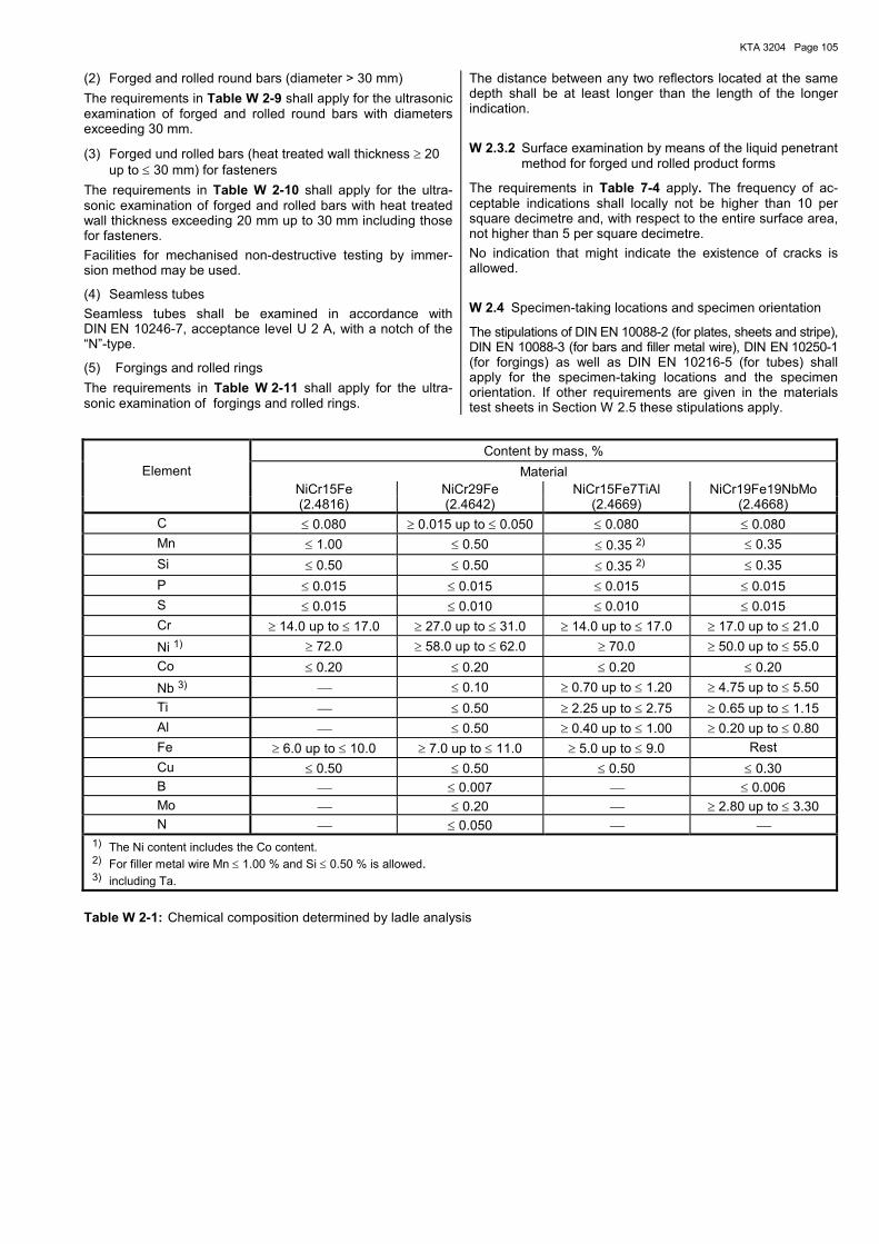
KTA 3204 Page 105
(2) Forged and rolled round bars (diameter > 30 mm) The requirements in Table W 2-9 shall apply for the ultrasonic examination of forged and rolled round bars with diameters exceeding 30 mm.
(3) Forged und rolled bars (heat treated wall thickness ≥ 20 up to ≤ 30 mm) for fasteners
The requirements in Table W 2-10 shall apply for the ultra-sonic examination of forged and rolled bars with heat treated wall thickness exceeding 20 mm up to 30 mm including those for fasteners. Facilities for mechanised non-destructive testing by immer-sion method may be used.
(4) Seamless tubes Seamless tubes shall be examined in accordance with DIN EN 10246-7, acceptance level U 2 A, with a notch of the �N�-type.
(5) Forgings and rolled rings The requirements in Table W 2-11 shall apply for the ultra-sonic examination of forgings and rolled rings.
The distance between any two reflectors located at the same depth shall be at least longer than the length of the longer indication.
W 2.3.2 Surface examination by means of the liquid penetrant method for forged und rolled product forms
The requirements in Table 7-4 apply. The frequency of ac-ceptable indications shall locally not be higher than 10 per square decimetre and, with respect to the entire surface area, not higher than 5 per square decimetre. No indication that might indicate the existence of cracks is allowed.
W 2.4 Specimen-taking locations and specimen orientation
The stipulations of DIN EN 10088-2 (for plates, sheets and stripe), DIN EN 10088-3 (for bars and filler metal wire), DIN EN 10250-1 (for forgings) as well as DIN EN 10216-5 (for tubes) shall apply for the specimen-taking locations and the specimen orientation. If other requirements are given in the materials test sheets in Section W 2.5 these stipulations apply.
Content by mass, %
Element Material NiCr15Fe NiCr29Fe NiCr15Fe7TiAl NiCr19Fe19NbMo (2.4816) (2.4642) (2.4669) (2.4668)
C ≤ 0.080 ≥ 0.015 up to ≤ 0.050 ≤ 0.080 ≤ 0.080 Mn ≤ 1.00 ≤ 0.50 ≤ 0.35 2) ≤ 0.35 Si ≤ 0.50 ≤ 0.50 ≤ 0.35 2) ≤ 0.35 P ≤ 0.015 ≤ 0.015 ≤ 0.015 ≤ 0.015 S ≤ 0.015 ≤ 0.010 ≤ 0.010 ≤ 0.015 Cr ≥ 14.0 up to ≤ 17.0 ≥ 27.0 up to ≤ 31.0 ≥ 14.0 up to ≤ 17.0 ≥ 17.0 up to ≤ 21.0
Ni 1) ≥ 72.0 ≥ 58.0 up to ≤ 62.0 ≥ 70.0 ≥ 50.0 up to ≤ 55.0 Co ≤ 0.20 ≤ 0.20 ≤ 0.20 ≤ 0.20
Nb 3) ≤ 0.10 ≥ 0.70 up to ≤ 1.20 ≥ 4.75 up to ≤ 5.50 Ti ≤ 0.50 ≥ 2.25 up to ≤ 2.75 ≥ 0.65 up to ≤ 1.15 Al ≤ 0.50 ≥ 0.40 up to ≤ 1.00 ≥ 0.20 up to ≤ 0.80 Fe ≥ 6.0 up to ≤ 10.0 ≥ 7.0 up to ≤ 11.0 ≥ 5.0 up to ≤ 9.0 Rest Cu ≤ 0.50 ≤ 0.50 ≤ 0.50 ≤ 0.30 B ≤ 0.007 ≤ 0.006 Mo ≤ 0.20 ≥ 2.80 up to ≤ 3.30 N ≤ 0.050 1) The Ni content includes the Co content. 2) For filler metal wire Mn ≤ 1.00 % and Si ≤ 0.50 % is allowed. 3) including Ta.
Table W 2-1: Chemical composition determined by ladle analysis
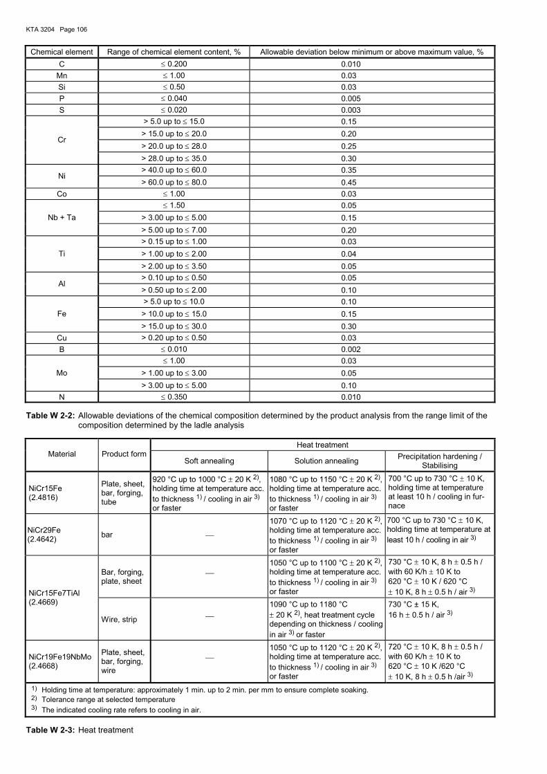
KTA 3204 Page 106
Chemical element Range of chemical element content, % Allowable deviation below minimum or above maximum value, % C ≤ 0.200 0.010
Mn ≤ 1.00 0.03 Si ≤ 0.50 0.03 P ≤ 0.040 0.005 S ≤ 0.020 0.003
> 5.0 up to ≤ 15.0 0.15 > 15.0 up to ≤ 20.0 0.20 > 20.0 up to ≤ 28.0 0.25
Cr
> 28.0 up to ≤ 35.0 0.30 > 40.0 up to ≤ 60.0 0.35
Ni > 60.0 up to ≤ 80.0 0.45
Co ≤ 1.00 0.03 ≤ 1.50 0.05
> 3.00 up to ≤ 5.00 0.15 Nb + Ta > 5.00 up to ≤ 7.00 0.20 > 0.15 up to ≤ 1.00 0.03 > 1.00 up to ≤ 2.00 0.04 Ti > 2.00 up to ≤ 3.50 0.05 > 0.10 up to ≤ 0.50 0.05
Al > 0.50 up to ≤ 2.00 0.10 > 5.0 up to ≤ 10.0 0.10 > 10.0 up to ≤ 15.0 0.15 Fe > 15.0 up to ≤ 30.0 0.30
Cu > 0.20 up to ≤ 0.50 0.03 B ≤ 0.010 0.002
≤ 1.00 0.03 > 1.00 up to ≤ 3.00 0.05 Mo > 3.00 up to ≤ 5.00 0.10
N ≤ 0.350 0.010
Table W 2-2: Allowable deviations of the chemical composition determined by the product analysis from the range limit of the composition determined by the ladle analysis
Heat treatment Material
Product form
Soft annealing Solution annealing Precipitation hardening / Stabilising
NiCr15Fe (2.4816)
Plate, sheet, bar, forging, tube
920 °C up to 1000 °C ± 20 K 2), holding time at temperature acc. to thickness 1) / cooling in air 3) or faster
1080 °C up to 1150 °C ± 20 K 2), holding time at temperature acc. to thickness 1) / cooling in air 3) or faster
700 °C up to 730 °C ± 10 K, holding time at temperature at least 10 h / cooling in fur-nace
NiCr29Fe (2.4642) bar
1070 °C up to 1120 °C ± 20 K 2), holding time at temperature acc. to thickness 1) / cooling in air 3) or faster
700 °C up to 730 °C ± 10 K, holding time at temperature at least 10 h / cooling in air 3)
Bar, forging, plate, sheet
1050 °C up to 1100 °C ± 20 K 2), holding time at temperature acc. to thickness 1) / cooling in air 3) or faster
730 °C ± 10 K, 8 h ± 0.5 h / with 60 K/h ± 10 K to 620 °C ± 10 K / 620 °C ± 10 K, 8 h ± 0.5 h / air 3) NiCr15Fe7TiAl
(2.4669)
Wire, strip
1090 °C up to 1180 °C ± 20 K 2), heat treatment cycle depending on thickness / cooling in air 3) or faster
730 °C ± 15 K, 16 h ± 0.5 h / air 3)
NiCr19Fe19NbMo (2.4668)
Plate, sheet, bar, forging, wire
1050 °C up to 1120 °C ± 20 K 2), holding time at temperature acc. to thickness 1) / cooling in air 3) or faster
720 °C ± 10 K, 8 h ± 0.5 h / with 60 K/h ± 10 K to 620 °C ± 10 K /620 °C ± 10 K, 8 h ± 0.5 h /air 3)
1) Holding time at temperature: approximately 1 min. up to 2 min. per mm to ensure complete soaking. 2) Tolerance range at selected temperature 3) The indicated cooling rate refers to cooling in air.
Table W 2-3: Heat treatment
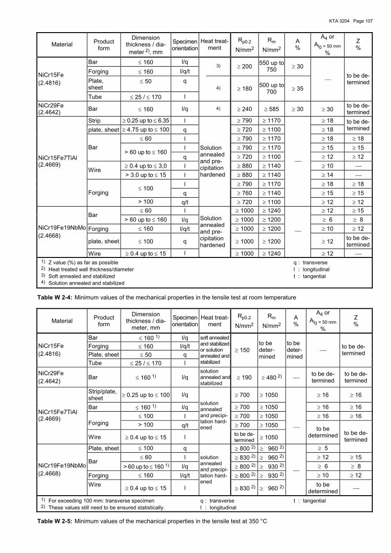
KTA 3204 Page 107
Material Product form
Dimension thickness / dia-meter 2), mm
Specimenorientation
Heat treat-ment
Rp0.2
N/mm2
Rm
N/mm2 A %
A4 or Al0 = 50 mm
%
Z %
Bar ≤ 160 l/q Forging ≤ 160 l/q/t
3) ≥ 200 550 up to 750 ≥ 30
Plate, sheet
≤ 50 q NiCr15Fe (2.4816)
Tube ≤ 25 / ≤ 170 l 4) ≥ 180 500 up to
700 ≥ 35 to be de-
termined
NiCr29Fe (2.4642) Bar ≤ 160 l/q 4) ≥ 240 ≥ 585 ≥ 30 ≥ 30 to be de-
terminedStrip ≥ 0.25 up to ≤ 6.35 l ≥ 790 ≥ 1170 ≥ 18 plate, sheet ≥ 4.75 up to ≤ 100 q ≥ 720 ≥ 1100 ≥ 18
to be de-termined
≤ 60 l ≥ 790 ≥ 1170 ≥ 18 ≥ 18 l ≥ 790 ≥ 1170 ≥ 15 ≥ 15 Bar
> 60 up to ≤ 160 q ≥ 720 ≥ 1100 ≥ 12 ≥ 12
≥ 0.4 up to ≤ 3,0 l ≥ 880 ≥ 1140 ≥ 10 Wire
> 3.0 up to ≤ 15 l ≥ 880 ≥ 1140 ≥ 14 l ≥ 790 ≥ 1170 ≥ 18 ≥ 18
≤ 100 q ≥ 760 ≥ 1140 ≥ 15 ≥ 15
NiCr15Fe7TiAl (2.4669)
Forging > 100 q/t
Solution annealed and pre-cipitation hardened
≥ 720 ≥ 1100
≥ 12 ≥ 12 ≤ 60 l ≥ 1000 ≥ 1240 ≥ 12 ≥ 15
Bar > 60 up to ≤ 160 l/q ≥ 1000 ≥ 1200 ≥ 6 ≥ 8
Forging ≤ 160 l/q/t ≥ 1000 ≥ 1200 ≥ 10 ≥ 12
plate, sheet ≤ 100 q ≥ 1000 ≥ 1200 ≥ 12 to be de-termined
NiCr19Fe19NbMo (2.4668)
Wire ≥ 0.4 up to ≤ 15 l
Solution annealed and pre-cipitation hardened
≥ 1000 ≥ 1240
≥ 12 1) Z value (%) as far as possible q : transverse 2) Heat treated wall thickness/diameter l : longitudinal 3) Soft annealed and stabilized t : tangential 4) Solution annealed and stabilized
Table W 2-4: Minimum values of the mechanical properties in the tensile test at room temperature
Material Product form
Dimension thickness / dia-
meter, mm
Specimen orientation
Heat treat-ment
Rp0.2
N/mm2
Rm
N/mm2 A %
A4 or Al0 = 50 mm
%
Z %
Bar ≤ 160 1) l/q Forging ≤ 160 l/q/t Plate, sheet ≤ 50 q
NiCr15Fe (2.4816)
Tube ≤ 25 / ≤ 170 l
soft annealed and stabilized or solution annealed and stabilized
≥ 150 to be deter-mined
to be deter-mined
to be de-termined
NiCr29Fe (2.4642)
Bar ≤ 160 1) l/q solution annealed andstabilized
≥ 190 ≥ 480 2) to be de-termined
to be de-termined
Strip/plate, sheet ≥ 0.25 up to ≤ 100 l/q ≥ 700 ≥ 1050 ≥ 16 ≥ 16
Bar ≤ 160 1) l/q ≥ 700 ≥ 1050 ≥ 16 ≥ 16 ≤ 100 l ≥ 700 ≥ 1050 ≥ 16 ≥ 16
Forging > 100 q/t ≥ 700 ≥ 1050
NiCr15Fe7TiAl (2.4669)
Wire ≥ 0.4 up to ≤ 15 l
solution annealed and precipi-tation hard-ened
to be de-termined ≥ 1050
to be determined
Plate, sheet ≤ 100 q ≥ 800 2) ≥ 960 2) ≥ 5
to be de-termined
≤ 60 l ≥ 830 2) ≥ 960 2) ≥ 12 ≥ 15 Bar
> 60 up to ≤ 160 1) l/q ≥ 800 2) ≥ 930 2) ≥ 6 ≥ 8 Forging ≤ 160 l/q/t ≥ 800 2) ≥ 930 2) ≥ 10 ≥ 12
NiCr19Fe19NbMo (2.4668)
Wire ≥ 0.4 up to ≤ 15 l
solution annealed and precipi-tation hard-ened
≥ 830 2) ≥ 960 2)
to be determined
1) For exceeding 100 mm: transverse specimen q : transverse t : tangential 2) These values still need to be ensured statistically. l : longitudinal
Table W 2-5: Minimum values of the mechanical properties in the tensile test at 350 °C
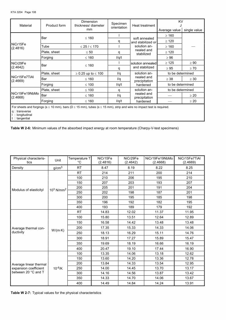
KTA 3204 Page 108
KV J Material Product form
Dimension thickness/ diameter
mm
Specimen orientation Heat treatment
Average value single value l ≥ 160
Bar ≤ 160 q ≥ 120
Tube ≤ 25 / ≤ 170 l ≥ 160 Plate, sheet ≤ 50 q ≥ 120
NiCr15Fe (2.4816)
Forging ≤ 160 l/q/t
soft annealedand stabilized or
solution an-nealed and stabilized
≥ 96
l ≥ 125 ≥ 90 NiCr29Fe (2.4642) Bar ≤ 160
q solution annealed
and stabilized ≥ 95 ≥ 70 Plate, sheet ≥ 0.25 up to ≤ 100 l/q to be determined Bar ≤ 160 l/q ≥ 38 ≥ 30 NiCr15Fe7TiAl
(2.4669) Forging ≤ 100 l/q/t
solution an-nealed and precipitation
hardened to be determined Plate, sheet ≤ 100 q to be determined Bar ≤ 160 l/q ≥ 20 NiCr19Fe19NbMo
(2.4668) Forging ≤ 160 l/q/t
solution an-nealed and precipitation
hardened ≥ 20
For sheets and forgings (s ≤ 10 mm), bars (D ≤ 15 mm), tubes (s ≤ 15 mm), strip and wire no impact test is required. q : transverse l : longitudinal t : tangential
Table W 2-6: Minimum values of the absorbed impact energy at room temperature (Charpy-V-test specimens)
Physical characteris-
tics Unit Temperature T °C
NiCr15Fe (2.4816)
NiCr29Fe (2.4642)
NiCr19Fe19NbMo (2.4668)
NiCr15Fe7TiAl (2.4669)
Density g/cm3 RT 8.47 8.19 8.22 8.25 RT 214 211 200 214 100 210 206 195 210 150 207 203 193 207 200 205 201 191 204 250 202 198 187 201 300 200 195 185 198 350 196 192 182 195
Modulus of elasticityl 103 N/mm2
400 193 189 179 192 RT 14.83 12.02 11.37 11.95 100 15.80 13.51 12.64 12.89 150 16.58 14.42 13.48 13.48 200 17.35 15.33 14.33 14.06 250 18.13 16.29 15.11 14.76 300 18.91 17.27 15.89 15.47 350 19.69 18.19 16.66 16.19
Average thermal con-ductivity W/(m⋅K)
400 20.47 19.10 17.44 16.90 100 13.35 14.06 13.18 12.62 150 13.60 14.20 13.36 12.78 200 13.84 14.33 13.54 12.95 250 14.00 14.45 13.70 13.17 300 14.16 14.56 13.87 13.42 350 14.33 14.70 14.06 13.67
Average linear thermal expansion coefficient between 20 °C and T
10-6/K
400 14.49 14.84 14.24 13.91
Table W 2-7: Typical values for the physical characteristics
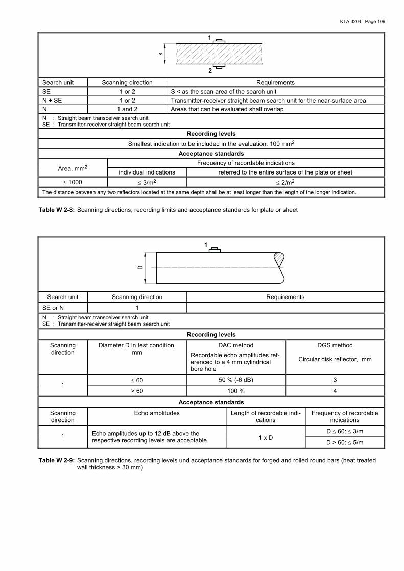
KTA 3204 Page 109
2
1
s
Search unit Scanning direction Requirements SE 1 or 2 S < as the scan area of the search unit N + SE 1 or 2 Transmitter-receiver straight beam search unit for the near-surface area N 1 and 2 Areas that can be evaluated shall overlap N : Straight beam transceiver search unit SE : Transmitter-receiver straight beam search unit
Recording levels
Smallest indication to be included in the evaluation: 100 mm2 Acceptance standards
Frequency of recordable indications Area, mm2 individual indications referred to the entire surface of the plate or sheet
≤ 1000 ≤ 3/m2 ≤ 2/m2 The distance between any two reflectors located at the same depth shall be at least longer than the length of the longer indication.
Table W 2-8: Scanning directions, recording limits and acceptance standards for plate or sheet
1
D
Search unit Scanning direction Requirements
SE or N 1 N : Straight beam transceiver search unit SE : Transmitter-receiver straight beam search unit
Recording levels
Scanning direction
Diameter D in test condition, mm
DAC method Recordable echo amplitudes ref-erenced to a 4 mm cylindrical bore hole
DGS method
Circular disk reflector, mm
≤ 60 50 % (-6 dB) 3 1
> 60 100 % 4
Acceptance standards
Scanning direction
Echo amplitudes Length of recordable indi-cations
Frequency of recordable indications
D ≤ 60: ≤ 3/m 1 Echo amplitudes up to 12 dB above the
respective recording levels are acceptable
1 x D D > 60: ≤ 5/m
Table W 2-9: Scanning directions, recording levels und acceptance standards for forged and rolled round bars (heat treated wall thickness > 30 mm)
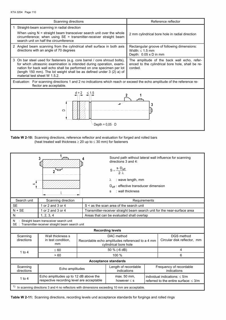
KTA 3204 Page 110
Scanning directions Reference reflector
1 Straight-beam scanning in radial direction When using N = straight beam transceiver search unit over the whole
circumference; when using SE = transmitter-receiver straight beam search unit on half the circumference
2 mm cylindrical bore hole in radial direction
2 Angled beam scanning from the cylindrical shell surface in both axis directions with an angle of 70 degrees
Rectangular groove of following dimensions: Width: ≤ 1.5 mm Depth: 0.05 x D in mm
3 On bar steel used for fasteners (e.g. core barrel / core shroud bolts), for which ultrasonic examination is intended during operation, exami-nation for back wall echo shall be performed on one specimen per lot (length 150 mm). The lot weight shall be as defined under 3 (2) a) of material test sheet W 1.5.2.
The amplitude of the back wall echo, refer-enced to the cylindrical bore hole, shall be re-corded.
Evaluation: For scanning directions 1 and 2 no indications which reach or exceed the echo amplitude of the reference re-flector are acceptable.
2 1
3
D
d = 2 ≤ 1.5
Depth = 0,05 D⋅
Table W 2-10: Scanning directions, reference reflector and evaluation for forged and rolled bars (heat treated wall thickness ≥ 20 up to ≤ 30 mm) for fasteners
43
2
1
s
Sound path without lateral wall influence for scanning directions 3 and 4:
λ⋅⋅
=2DsS eff
λ : wave length, mm
Deff : effective transducer dimension s : wall thickness
Search unit Scanning direction Requirements SE 1 or 2 and 3 or 4 S < as the scan area of the search unit N + SE 1 or 2 and 3 or 4 Transmitter-receiver straight beam search unit for the near-surface area N 1, 2, 3, 4 Areas that can be evaluated shall overlap N : Straight beam transceiver search unit SE : Transmitter-receiver straight beam search unit
Recording levels
Scanning directions
Wall thickness s in test condition,
mm
DAC method Recordable echo amplitudes referenced to a 4 mm
cylindrical bore hole
DGS method Circular disk reflector, mm
≤ 60 50 % (-6 dB) 4 1 to 4
> 60 100 % 6
Acceptance standards
Scanning directions Echo amplitudes Length of recordable
indications Frequency of recordable
indications
1 to 4 Echo amplitudes up to 12 dB above the respective recording level are acceptable
max. 50 mm, however ≤ s
individual indications: ≤ 5/m referred to the entire surface: ≤ 3/m
1) In scanning directions 3 and 4 no reflectors with dimensions exceeding 10 mm are acceptable.
Table W 2-11: Scanning directions, recording levels und acceptance standards for forgings and rolled rings
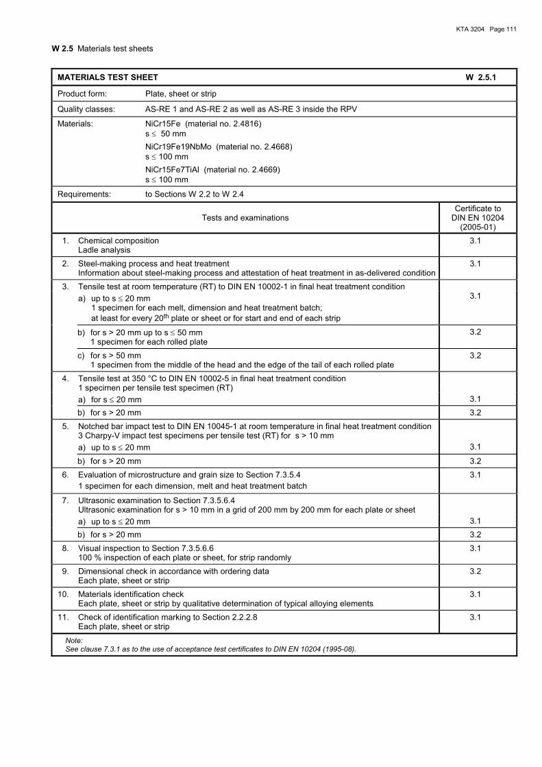
KTA 3204 Page 111
W 2.5 Materials test sheets
MATERIALS TEST SHEET W 2.5.1
Product form: Plate, sheet or strip
Quality classes: AS-RE 1 and AS-RE 2 as well as AS-RE 3 inside the RPV
Materials: NiCr15Fe (material no. 2.4816) s ≤ 50 mm NiCr19Fe19NbMo (material no. 2.4668) s ≤ 100 mm NiCr15Fe7TiAl (material no. 2.4669) s ≤ 100 mm
Requirements: to Sections W 2.2 to W 2.4
Tests and examinations Certificate to
DIN EN 10204 (2005-01)
1. Chemical composition Ladle analysis
3.1
2. Steel-making process and heat treatment Information about steel-making process and attestation of heat treatment in as-delivered condition
3.1
3. Tensile test at room temperature (RT) to DIN EN 10002-1 in final heat treatment condition a) up to s ≤ 20 mm 1 specimen for each melt, dimension and heat treatment batch; at least for every 20th plate or sheet or for start and end of each strip
3.1
b) for s > 20 mm up to s ≤ 50 mm 1 specimen for each rolled plate
3.2
c) for s > 50 mm 1 specimen from the middle of the head and the edge of the tail of each rolled plate
3.2
4. Tensile test at 350 °C to DIN EN 10002-5 in final heat treatment condition 1 specimen per tensile test specimen (RT)
a) for s ≤ 20 mm 3.1
b) for s > 20 mm 3.2
5. Notched bar impact test to DIN EN 10045-1 at room temperature in final heat treatment condition 3 Charpy-V impact test specimens per tensile test (RT) for s > 10 mm
a) up to s ≤ 20 mm 3.1
b) for s > 20 mm 3.2
6. Evaluation of microstructure and grain size to Section 7.3.5.4 1 specimen for each dimension, melt and heat treatment batch
3.1
7. Ultrasonic examination to Section 7.3.5.6.4 Ultrasonic examination for s > 10 mm in a grid of 200 mm by 200 mm for each plate or sheet
a) up to s ≤ 20 mm 3.1
b) for s > 20 mm 3.2
8. Visual inspection to Section 7.3.5.6.6 100 % inspection of each plate or sheet, for strip randomly
3.1
9. Dimensional check in accordance with ordering data Each plate, sheet or strip
3.2
10. Materials identification check Each plate, sheet or strip by qualitative determination of typical alloying elements
3.1
11. Check of identification marking to Section 2.2.2.8 Each plate, sheet or strip
3.1
Note: See clause 7.3.1 as to the use of acceptance test certificates to DIN EN 10204 (1995-08).
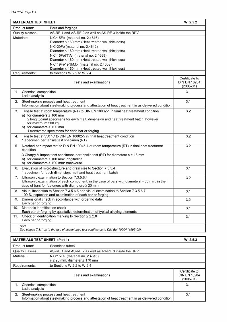
KTA 3204 Page 112
MATERIALS TEST SHEET W 2.5.2 Product form: Bars and forgings Quality classes: AS-RE 1 and AS-RE 2 as well as AS-RE 3 inside the RPV Materials: NiCr15Fe (material no. 2.4816) Diameter ≤ 160 mm (Heat treated wall thickness) NiCr29Fe (material no. 2.4642) Diameter ≤ 160 mm (Heat treated wall thickness) NiCr15Fe7TiAl (material no. 2.4669) Diameter ≤ 160 mm (Heat treated wall thickness) NiCr19Fe19NbMo (material no. 2.4668) Diameter ≤ 160 mm (Heat treated wall thickness) Requirements: to Sections W 2.2 to W 2.4
Tests and examinations Certificate to
DIN EN 10204 (2005-01)
1. Chemical composition Ladle analysis
3.1
2. Steel-making process and heat treatment Information about steel-making process and attestation of heat treatment in as-delivered condition
3.1
3. Tensile test at room temperature (RT) to DIN EN 10002-1 in final heat treatment condition a) for diameters ≤ 100 mm 2 longitudinal specimens for each melt, dimension and heat treatment batch, however for maximum 500 kg b) for diameters > 100 mm 1 transverse specimens for each bar or forging
3.2
4. Tensile test at 350 °C to DIN EN 10002-5 in final heat treatment condition 1 specimen per tensile test specimen (RT)
3.2
5. Notched bar impact test to DIN EN 10045-1 at room temperature (RT) in final heat treatment condition
3 Charpy-V impact test specimens per tensile test (RT) for diameters s > 15 mm a) for diameters ≤ 100 mm: longitudinal b) for diameters > 100 mm: transverse
3.2
6. Evaluation of microstructure and grain size to Section 7.3.5.4 1 specimen for each dimension, melt and heat treatment batch
3.1
7. Ultrasonic examination to Section 7.3.5.6.4 Ultrasonic examination of each component, in the case of bars with diameters > 30 mm, in the
case of bars for fasteners with diameters ≥ 20 mm
3.2
8. Visual inspection to Section 7.3.5.6.6 and visual examination to Section 7.3.5.6.7 100 % inspection and examination of each bar or forging
3.1
9. Dimensional check in accordance with ordering data Each bar or forging
3.2
10. Materials identification check Each bar or forging by qualitative determination of typical alloying elements
3.1
11. Check of identification marking to Section 2.2.2.8 Each bar or forging
3.1
Note: See clause 7.3.1 as to the use of acceptance test certificates to DIN EN 10204 (1995-08).
MATERIALS TEST SHEET (Part 1) W 2.5.3
Product form: Seamless tubes Quality classes: AS-RE 1 and AS-RE 2 as well as AS-RE 3 inside the RPV Material: NiCr15Fe (material no. 2.4816) s ≤ 25 mm, diameter ≤ 170 mm Requirements: to Sections W 2.2 to W 2.4
Tests and examinations Certificate to
DIN EN 10204 (2005-01)
1. Chemical composition Ladle analysis
3.1
2. Steel-making process and heat treatment Information about steel-making process and attestation of heat treatment in as-delivered condition
3.1
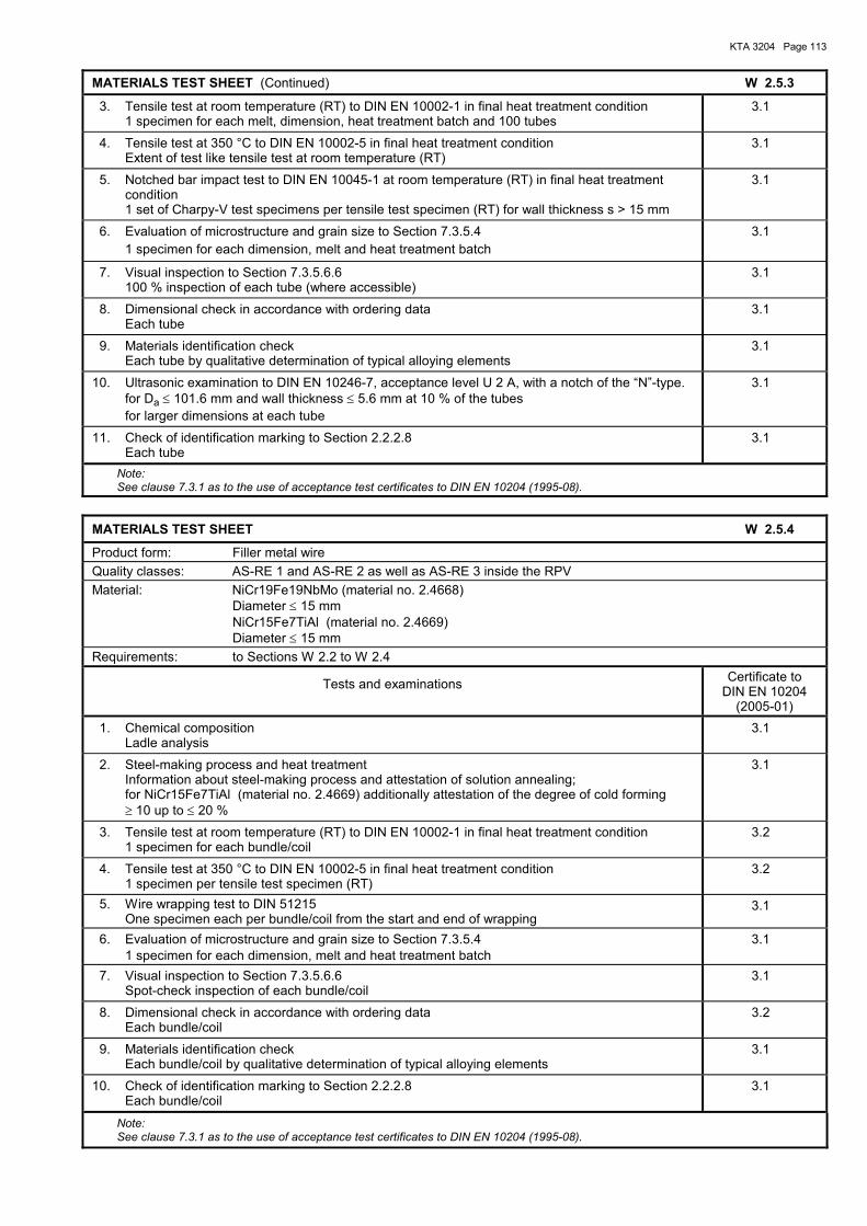
KTA 3204 Page 113
MATERIALS TEST SHEET (Continued) W 2.5.3
3. Tensile test at room temperature (RT) to DIN EN 10002-1 in final heat treatment condition 1 specimen for each melt, dimension, heat treatment batch and 100 tubes
3.1
4. Tensile test at 350 °C to DIN EN 10002-5 in final heat treatment condition Extent of test like tensile test at room temperature (RT)
3.1
5. Notched bar impact test to DIN EN 10045-1 at room temperature (RT) in final heat treatment condition 1 set of Charpy-V test specimens per tensile test specimen (RT) for wall thickness s > 15 mm
3.1
6. Evaluation of microstructure and grain size to Section 7.3.5.4 1 specimen for each dimension, melt and heat treatment batch
3.1
7. Visual inspection to Section 7.3.5.6.6 100 % inspection of each tube (where accessible)
3.1
8. Dimensional check in accordance with ordering data Each tube
3.1
9. Materials identification check Each tube by qualitative determination of typical alloying elements
3.1
10. Ultrasonic examination to DIN EN 10246-7, acceptance level U 2 A, with a notch of the �N�-type. for Da ≤ 101.6 mm and wall thickness ≤ 5.6 mm at 10 % of the tubes for larger dimensions at each tube
3.1
11. Check of identification marking to Section 2.2.2.8 Each tube
3.1
Note: See clause 7.3.1 as to the use of acceptance test certificates to DIN EN 10204 (1995-08).
MATERIALS TEST SHEET W 2.5.4
Product form: Filler metal wire Quality classes: AS-RE 1 and AS-RE 2 as well as AS-RE 3 inside the RPV Material: NiCr19Fe19NbMo (material no. 2.4668) Diameter ≤ 15 mm NiCr15Fe7TiAl (material no. 2.4669) Diameter ≤ 15 mm Requirements: to Sections W 2.2 to W 2.4
Tests and examinations Certificate to DIN EN 10204
(2005-01) 1. Chemical composition
Ladle analysis 3.1
2. Steel-making process and heat treatment Information about steel-making process and attestation of solution annealing; for NiCr15Fe7TiAl (material no. 2.4669) additionally attestation of the degree of cold forming ≥ 10 up to ≤ 20 %
3.1
3. Tensile test at room temperature (RT) to DIN EN 10002-1 in final heat treatment condition 1 specimen for each bundle/coil
3.2
4. Tensile test at 350 °C to DIN EN 10002-5 in final heat treatment condition 1 specimen per tensile test specimen (RT)
3.2
5. Wire wrapping test to DIN 51215 One specimen each per bundle/coil from the start and end of wrapping
3.1
6. Evaluation of microstructure and grain size to Section 7.3.5.4 1 specimen for each dimension, melt and heat treatment batch
3.1
7. Visual inspection to Section 7.3.5.6.6 Spot-check inspection of each bundle/coil
3.1
8. Dimensional check in accordance with ordering data Each bundle/coil
3.2
9. Materials identification check Each bundle/coil by qualitative determination of typical alloying elements
3.1
10. Check of identification marking to Section 2.2.2.8 Each bundle/coil
3.1
Note: See clause 7.3.1 as to the use of acceptance test certificates to DIN EN 10204 (1995-08).
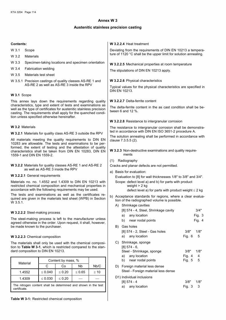
KTA 3204 Page 114
Annex W 3
Austenitic stainless precision casting
Contents:
W 3.1 Scope
W 3.2 Materials
W 3.3 Specimen-taking locations and specimen orientation
W 3.4 Fabrication welding
W 3.5 Materials test sheet
W 3.5.1 Precision castings of quality classes AS-RE 1 and AS-RE 2 as well as AS-RE 3 inside the RPV
W 3.1 Scope
This annex lays down the requirements regarding quality characteristics, type and extent of tests and examinations as well as the type of certificates for austenitic stainless precision casting. The requirements shall apply for the quenched condi-tion unless specified otherwise hereinafter.
W 3.2 Materials
W 3.2.1 Materials for quality class AS-RE 3 outside the RPV
All materials meeting the quality requirements to DIN EN 10283 are allowable. The tests and examinations to be per-formed, the extent of testing and the attestation of quality characteristics shall be taken from DIN EN 10283, DIN EN 1559-1 and DIN EN 1559-2.
W 3.2.2 Materials for quality classes AS-RE 1 and AS-RE 2 as well as AS-RE 3 inside the RPV
W 3.2.2.1 General requirements
Materials no. no. 1.4552 and 1.4309 to DIN EN 10213 with restricted chemical composition and mechanical properties in accordance with the following requirements may be used. The tests and examinations as well as the certificates re-quired are given in the materials test sheet (WPB) in Section W 3.5.1.
W 3.2.2.2 Steel-making process
The steel-making process is left to the manufacturer unless agreed otherwise in the order. Upon request, it shall, however, be made known to the purchaser.
W 3.2.2.3 Chemical composition
The materials shall only be used with the chemical composi-tion to Table W 3-1, which is restricted compared to the stan-dard composition to DIN EN 10213.
Content by mass, % Material
C Co Nb Nb/C
1.4552 ≤ 0.040 ≤ 0.20 ≤ 0.65 ≥ 10
1.4309 ≤ 0.030 ≤ 0.20
The nitrogen content shall be determined and shown in the test certificate.
Table W 3-1: Restricted chemical composition
W 3.2.2.4 Heat treatment
Deviating from the requirements of DIN EN 10213 a tempera-ture of 1120 °C shall be the upper limit for solution annealing.
W 3.2.2.5 Mechanical properties at room temperature
The stipulations of DIN EN 10213 apply.
W 3.2.2.6 Physical characteristics
Typical values for the physical characteristics are specified in DIN EN 10213.
W 3.2.2.7 Delta-ferrite content
The delta-ferrite content in the as cast condition shall be be-tween 6 and 12 %.
W 3.2.2.8 Resistance to intergranular corrosion
The resistance to intergranular corrosion shall be demonstra-ted in accordance with DIN EN ISO 3651-2 procedure A. The solution annealing shall be performed in accordance with clause 7.3.5.5 (2).
W 3.2.3 Non-destructive examinations and quality require-ments
(1) Radiography Cracks and planar defects are not permitted.
a) Basis for evaluation: Evaluation to [8] for wall thicknesses 1/8" to 3/8" and 3/4". Scope: defect level a) and b) for parts with product
weight > 2 kg defect level a) for parts with product weight ≤ 2 kg
b) Acceptance standards for regions, where a clear evalua-tion of the radiographed volume is possible. A) Shrinkage cavities [8] 574 - 4, Steel, Shrinkage cavity 3/4" a) any location Fig. 3 b) near nodal points Fig. 4
B) Gas holes [8] 574 - 2, Steel - Gas holes 3/8" 1/8" a) any location Fig. 6 5
C) Shrinkage, sponge [8] 574 - 6, Steel - Shrinkage, sponge 3/8" 1/8" a) any location Fig. 4 4 b) near nodal points Fig. 5 5
D) Foreign material less dense Steel - Foreign material less dense
D1) Individual inclusions [8] 574 - 4 3/8" 1/8" a) any location Fig. 3 3
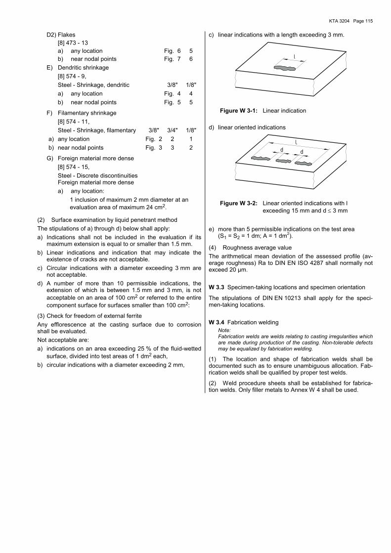
KTA 3204 Page 115
D2) Flakes [8] 473 - 13 a) any location Fig. 6 5 b) near nodal points Fig. 7 6 E) Dendritic shrinkage [8] 574 - 9, Steel - Shrinkage, dendritic 3/8" 1/8" a) any location Fig. 4 4 b) near nodal points Fig. 5 5
F) Filamentary shrinkage [8] 574 - 11, Steel - Shrinkage, filamentary 3/8" 3/4" 1/8" a) any location Fig. 2 2 1 b) near nodal points Fig. 3 3 2
G) Foreign material more dense [8] 574 - 15, Steel - Discrete discontinuities
Foreign material more dense a) any location:
1 inclusion of maximum 2 mm diameter at an evaluation area of maximum 24 cm2.
(2) Surface examination by liquid penetrant method The stipulations of a) through d) below shall apply: a) Indications shall not be included in the evaluation if its
maximum extension is equal to or smaller than 1.5 mm. b) Linear indications and indication that may indicate the
existence of cracks are not acceptable. c) Circular indications with a diameter exceeding 3 mm are
not acceptable. d) A number of more than 10 permissible indications, the
extension of which is between 1.5 mm and 3 mm, is not acceptable on an area of 100 cm2 or referred to the entire component surface for surfaces smaller than 100 cm2:
(3) Check for freedom of external ferrite Any efflorescence at the casting surface due to corrosion shall be evaluated. Not acceptable are: a) indications on an area exceeding 25 % of the fluid-wetted
surface, divided into test areas of 1 dm2 each, b) circular indications with a diameter exceeding 2 mm,
c) linear indications with a length exceeding 3 mm.
Figure W 3-1: Linear indication
d) linear oriented indications
d d
Figure W 3-2: Linear oriented indications with l exceeding 15 mm and d ≤ 3 mm
e) more than 5 permissible indications on the test area (S1 = S2 = 1 dm; A = 1 dm2).
(4) Roughness average value The arithmetical mean deviation of the assessed profile (av-erage roughness) Ra to DIN EN ISO 4287 shall normally not exceed 20 µm.
W 3.3 Specimen-taking locations and specimen orientation
The stipulations of DIN EN 10213 shall apply for the speci-men-taking locations.
W 3.4 Fabrication welding Note: Fabrication welds are welds relating to casting irregularities which are made during production of the casting. Non-tolerable defects may be equalized by fabrication welding.
(1) The location and shape of fabrication welds shall be documented such as to ensure unambiguous allocation. Fab-rication welds shall be qualified by proper test welds.
(2) Weld procedure sheets shall be established for fabrica-tion welds. Only filler metals to Annex W 4 shall be used.
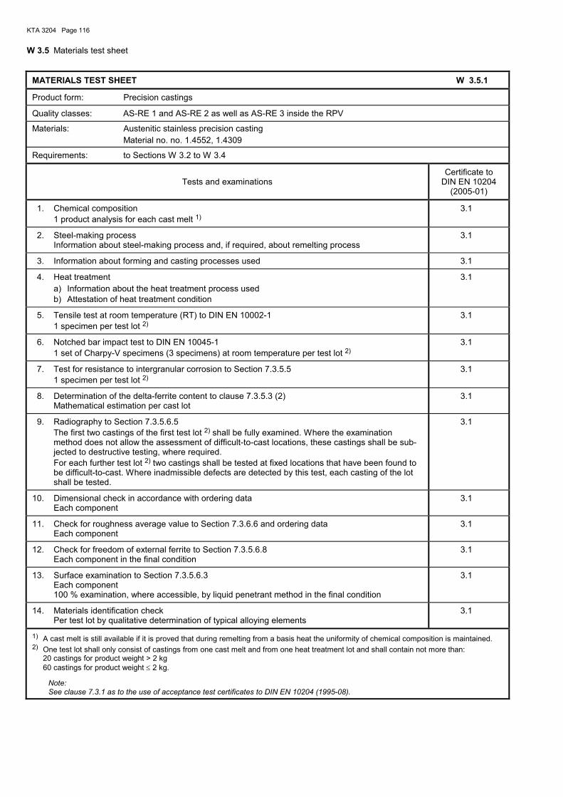
KTA 3204 Page 116
W 3.5 Materials test sheet
MATERIALS TEST SHEET W 3.5.1
Product form: Precision castings
Quality classes: AS-RE 1 and AS-RE 2 as well as AS-RE 3 inside the RPV
Materials: Austenitic stainless precision casting Material no. no. 1.4552, 1.4309
Requirements: to Sections W 3.2 to W 3.4
Tests and examinations Certificate to
DIN EN 10204 (2005-01)
1. Chemical composition 1 product analysis for each cast melt 1)
3.1
2. Steel-making process Information about steel-making process and, if required, about remelting process
3.1
3. Information about forming and casting processes used 3.1
4. Heat treatment a) Information about the heat treatment process used b) Attestation of heat treatment condition
3.1
5. Tensile test at room temperature (RT) to DIN EN 10002-1 1 specimen per test lot 2)
3.1
6. Notched bar impact test to DIN EN 10045-1 1 set of Charpy-V specimens (3 specimens) at room temperature per test lot 2)
3.1
7. Test for resistance to intergranular corrosion to Section 7.3.5.5 1 specimen per test lot 2)
3.1
8. Determination of the delta-ferrite content to clause 7.3.5.3 (2) Mathematical estimation per cast lot
3.1
9. Radiography to Section 7.3.5.6.5 The first two castings of the first test lot 2) shall be fully examined. Where the examination
method does not allow the assessment of difficult-to-cast locations, these castings shall be sub-jected to destructive testing, where required. For each further test lot 2) two castings shall be tested at fixed locations that have been found to be difficult-to-cast. Where inadmissible defects are detected by this test, each casting of the lot shall be tested.
3.1
10. Dimensional check in accordance with ordering data Each component
3.1
11. Check for roughness average value to Section 7.3.6.6 and ordering data Each component
3.1
12. Check for freedom of external ferrite to Section 7.3.5.6.8 Each component in the final condition
3.1
13. Surface examination to Section 7.3.5.6.3 Each component
100 % examination, where accessible, by liquid penetrant method in the final condition
3.1
14. Materials identification check Per test lot by qualitative determination of typical alloying elements
3.1
1) A cast melt is still available if it is proved that during remelting from a basis heat the uniformity of chemical composition is maintained. 2) One test lot shall only consist of castings from one cast melt and from one heat treatment lot and shall contain not more than:
20 castings for product weight > 2 kg 60 castings for product weight ≤ 2 kg.
Note: See clause 7.3.1 as to the use of acceptance test certificates to DIN EN 10204 (1995-08).
KTA 3204 Page 117
Annex W 4
Filler metals, brazing alloy and flux for thermal spraying Contents:
W 4.1 Scope
W 4.2 Materials W 4.2.1 Filler metals for quality class AS-RE 3 outside the RPV W 4.2.2 Filler metals for quality classes AS-RE 1 and
AS-RE 2 as well as AS-RE 3 inside the RPV W 4.2.3 Brazing alloy for quality classes AS-RE 1 and
AS-RE 2 as well as AS-RE 3 inside the RPV W 4.2.4 Filler metals for hard-surfacing and flux for thermal
spraying for quality classes AS-RE 1, AS-RE 2 and AS-RE 3
W 4.3 Materials test sheets W 4.3.1 Filler metals for austenitic Cr-Ni-steel for quality
classes AS-RE 1 and AS-RE 2 as well as AS-RE 3 inside the RPV
W 4.3.2 Filler metals for austenitic Cr-Ni-steel for quality class AS-RE 3 outside the RPV
W 4.3.3 Filler metals for Nickel-based alloys for quality classes AS-RE 1 and AS-RE 2 as well as AS-RE 3 inside the RPV
W 4.3.4 Filler metals für Nickel-based alloys for quality class AS-RE 3 outside the RPV
W 4.3.5 Filler metals for martensitic and ferritic steel for quality class AS-RE 3 outside the RPV
W 4.3.6 Brazing alloy for quality classes AS-RE 1, AS-RE 2 and AS-RE 3
W 4.3.7 Filler metals for hard-surfacing for quality classes AS-RE 1, AS-RE 2 and AS-RE 3
W 4.3.8 Flux for thermal spraying for quality classes AS-RE 1, AS-RE 2 and AS-RE 3
W 4.1 Scope
This annex lays down the requirements regarding quality characteristics, type and extent of tests and examinations as well as the type of certificates for filler metals for manual metal arc welding, gas tungsten arc welding, gas metal arc welding and submerged arc welding as well as for brazing alloy and flux for thermal spraying. The requirements shall apply for all-weld filler metals for the as-welded condition, for brazing alloy and flux for thermal spraying for the as-delivered condition unless specified otherwise hereinafter.
W 4.2 Materials
W 4.2.1 Filler metals and flux for thermal spraying for quality class AS-RE 3 outside the RPV
(1) Austenitic chrome/nickel steels All filler metals with the abbreviated identification 19 9 nC, 19 9 L, 19 9 Nb and 19 12 3 Nb meeting the quality require-ments to DIN EN 1600, DIN EN ISO 14343 and DIN EN ISO 17633 are allowable. The tests and examinations to be per-formed and the attestation of quality characteristics shall be taken from the materials test sheet (WPB) to Section W 4.3.2.
(2) Nickel alloys Filler metals with the abbreviated identification NiCr20Mn3Nb (NI 6082) (material no. 2.4648), NiCr20Mn3Nb (NI 6082) (material no. 2.4806) and S-NiCr15Fe6Mn (material no. 2.4620) to DIN EN ISO 14172 and DIN EN ISO 18274 are allowable. For lock weldings filler metals with the abbreviated identifica-tion NiCr15Ti3Mn (NI 7092) (material no. 2.4803) are allow-
able additionally. The mechanical properties required are specified in Tables W 4-5 and W 4-6. The tests and examinations to be performed and the attesta-tion of quality characteristics shall be taken from the materials test sheet (WPB) to Section W 4.3.4.
(3) Martensitic and ferritic steel Filler metals with the abbreviated identification 13, 13 4 and 17 meeting the quality characteristics to DIN EN 1600, DIN EN ISO 14343 und DIN EN ISO 17633 as well as filler metals to DIN EN ISO 2560 for parts outside the reactor pressure vessel during operation are allowable. The tests and examinations to be performed and the attesta-tion of quality characteristics shall be taken from the materials test sheet (WPB) to Section W 4.3.5.
W 4.2.2 Filler metals for quality classes AS-RE 1 and AS-RE 2 as well as AS-RE 3 inside the RPV
(1) Austenitic chrome/nickel steels Filler metals with the abbreviated identifications 19 9 L and 19 9 Nb to DIN EN 1600 and DIN EN ISO 14343 with re-stricted chemical composition and mechanical properties given below may be used. The tests and examinations to be performed and the attesta-tion of quality characteristics shall be taken from the materials test sheet (WPB) to Section W 4.3.1.
A. Chemical composition and delta-ferrite content The materials shall only be used with the chemical composi-tion to Table W 4-1, which is restricted compared to the stan-dard composition to DIN EN 1600 and DIN EN ISO 14343.
Content by mass, % Material
C Nb 1) Co Nb/C
Delta-ferrite contentas-welded
condition, %
19 9 L ≤ 0.030
19 9 Nb ≤ 0.040 ≤ 0.65 2)
≤ 0.2 ≥ 13
4 up to 12
In any case the nitrogen content shall be determined and shown in the test certificate. In any case S ≤ 0.015 % (for rod electrodes to DIN EN 1600 with rutile coating however S ≤ 0.020 %) shall apply. For submerged arc welding metals Ni ≤ 12 % shall apply. 1) It is not permitted to substitute Nb by Ta. 2) For basic coated electrodes Nb ≤ 0.75 % shall apply.
Table W 4-1: Restricted chemical composition and delta-ferrite content of austenitic filler metals
B. Mechanical properties The mechanical properties required are specified in Ta-bles W 4-2 and W 4-3.
Test temperature Property RT 350 °C
Rp0.2 , N/mm2 ≥ 350 ≥ 180 Rp1.0 , N/mm2 ≥ 380 ≥ 210 Rm , N/mm2 ≥ 550 up to ≤ 750 ≥ 380 A , % ≥ 30 ≥ 20 Z , % to be determined
Table W 4-2: Minimum values of the mechanical properties of austenitic filler metals in the tensile test
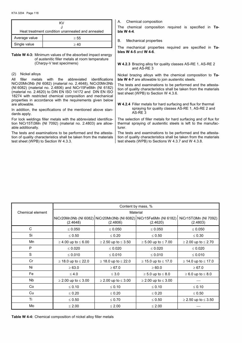
KTA 3204 Page 118
KV J
Heat treatment condition unannealed and annealed
Average value ≥ 55
Single value ≥ 40
Table W 4-3: Minimum values of the absorbed impact energy of austenitic filler metals at room temperature (Charpy-V test specimens)
(2) Nickel alloys All filler metals with the abbreviated identifications NiCr20Mn3Nb (NI 6082) (material no. 2.4648), NiCr20Mn3Nb (NI 6082) (material no. 2.4806) and NiCr15Fe6Mn (NI 6182) (material no. 2.4620) to DIN EN ISO 14172 and DIN EN ISO 18274 with restricted chemical composition and mechanical properties in accordance with the requirements given below are allowable. In addition, the specifications of the mentioned above stan-dards apply. For lock weldings filler metals with the abbreviated identifica-tion NiCr15Ti3Mn (NI 7092) (material no. 2.4803) are allow-able additionally. The tests and examinations to be performed and the attesta-tion of quality characteristics shall be taken from the materials test sheet (WPB) to Section W 4.3.3.
A. Chemical composition The chemical composition required is specified in Ta-ble W 4-4.
B. Mechanical properties
The mechanical properties required are specified in Ta-bles W 4-5 and W 4-6.
W 4.2.3 Brazing alloy for quality classes AS-RE 1, AS-RE 2 and AS-RE 3
Nickel brazing alloys with the chemical composition to Ta-ble W 4-7 are allowable to join austenitic steels. The tests and examinations to be performed and the attesta-tion of quality characteristics shall be taken from the materials test sheet (WPB) to Section W 4.3.6.
W 4.2.4 Filler metals for hard surfacing and flux for thermal spraying for quality classes AS-RE 1, AS-RE 2 and AS-RE 3
The selection of filler metals for hard surfacing and of flux for thermal spraying of austenitic steels is left to the manufac-turer. The tests and examinations to be performed and the attesta-tion of quality characteristics shall be taken from the materials test sheets (WPB) to Sections W 4.3.7 and W 4.3.8.
Content by mass, %
Chemical element Material NiCr20Mn3Nb (NI 6082) NiCr20Mn3Nb (NI 6082) NiCr15Fe6Mn (NI 6182) NiCr15Ti3Mn (NI 7092)
(2.4648) (2.4806) (2.4620) (2.4803)
C ≤ 0.050 ≤ 0.050 ≤ 0.050 ≤ 0.050
Si ≤ 0.50 ≤ 0.20 ≤ 0.50 ≤ 0.30
Mn ≥ 4.00 up to ≤ 6.00 ≥ 2.50 up to ≤ 3.50 ≥ 5.00 up to ≤ 7.00 ≥ 2.00 up to ≤ 2.70
P ≤ 0.020 ≤ 0.020 ≤ 0.020 ≤ 0.020
S ≤ 0.010 ≤ 0.010 ≤ 0.010 ≤ 0.010
Cr ≥ 18.0 up to ≤ 22.0 ≥ 18.0 up to ≤ 22.0 ≥ 15.0 up to ≤ 17.0 ≥ 14.0 up to ≤ 17.0
Ni ≥ 63.0 ≥ 67.0 ≥ 60.0 ≥ 67.0
Fe ≤ 4.0 ≤ 3.0 ≥ 5.0 up to ≤ 8.0 ≥ 6.0 up to ≤ 8.0
Nb ≥ 2.00 up to ≤ 3.00 ≥ 2.00 up to ≤ 3.00 ≥ 2.00 up to ≤ 3.00
Co ≤ 0.10 ≤ 0.10 ≤ 0.10 ≤ 0.10
Cu ≤ 0.20 ≤ 0.20 ≤ 0.20 ≤ 0.50
Ti ≤ 0.50 ≤ 0.70 ≤ 0.50 ≥ 2.50 up to ≤ 3.50
Mo ≤ 2.00 ≤ 2.00 ≤ 2.00
Table W 4-4: Chemical composition of nickel alloy filler metals
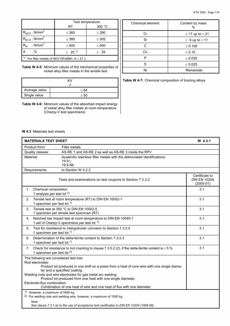
KTA 3204 Page 119
Test temperature RT 350 °C Rp0.2 , N/mm2 ≥ 360 ≥ 290
Rp1.0 , N/mm2 ≥ 380 ≥ 305
Rm , N/mm2 ≥ 600 ≥ 500
A , % ≥ 25 1) ≥ 25 1) For filler metals of NiCr15Fe6Mn: A ≥ 27 J
Table W 4-5: Minimum values of the mechanical properties of nickel alloy filler metals in the tensile test
KV J
Average value ≥ 64 Single value ≥ 50
Table W 4-6: Minimum values of the absorbed impact energy of nickel alloy filler metals at room temperature (Charpy-V test specimens)
Chemical element Content by mass %
Cr ≥ 17 up to ≤ 21
Si ≥ 9 up to ≤ 11
C ≤ 0.100
Co ≤ 0.10
P ≤ 0.035
S ≤ 0.025
Ni Remainder
Table W 4-7: Chemical composition of brazing alloys
W 4.3 Materials test sheets
MATERIALS TEST SHEET W 4.3.1
Product form: Filler metals Quality classes: AS-RE 1 and AS-RE 2 as well as AS-RE 3 inside the RPV Material: Austenitic stainless filler metals with the abbreviated identifications:
19 9 L 19 9 Nb
Requirements: to Section W 4.2.2
Tests and examinations on test coupons to Section 7.3.3.2 Certificate to
DIN EN 10204 (2005-01)
1. Chemical composition 3.1 1 analysis per test lot 2)
2. Tensile test at room temperature (RT) to DIN EN 10002-1 3.1 1 specimen per test lot 1)
3. Tensile test at 350 °C to DIN EN 10002-5 3.1 1 specimen per tensile test specimen (RT) 4. Notched bar impact test at room temperature to DIN EN 10045-1 3.1 1 set of Charpy-V specimens per test lot 1)
5. Test for resistance to intergranular corrosion to Section 7.3.5.5 3.1 1 specimen per test lot 1)
6. Determination of the delta-ferrite content to Section 7.3.5.3 3.1 1 specimen per test lot 1)
7. Check for resistance to hot cracking to clause 7.3.5.2 (2), if the delta-ferrite content is ≤ 5 % 3.1 1 specimen per test lot 2)
The following are considered test lots: Rod electrodes:
Product lot produced in one shift on a press from a heat of core wire with one single diame-ter and a specified coating.
Welding rods and wire electrodes for gas metal arc welding: Product lot produced from one heat with one single diameter.
Electrode-flux combination: Combination of one heat of wire and one heat of flux with one diameter.
1) However, a maximum of 5000 kg. 2) For welding rods and welding wire, however, a maximum of 1000 kg.
Note: See clause 7.3.1 as to the use of acceptance test certificates to DIN EN 10204 (1995-08).
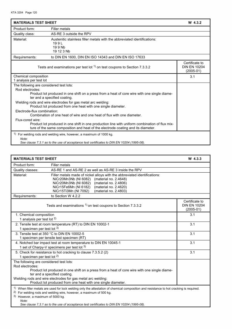
KTA 3204 Page 120
MATERIALS TEST SHEET W 4.3.2
Product form: Filler metals Quality class: AS-RE 3 outside the RPV Material: Austenitic stainless filler metals with the abbreviated identifications: 19 9 L 19 9 Nb 19 12 3 Nb
Requirements: to DIN EN 1600, DIN EN ISO 14343 and DIN EN ISO 17633
Tests and examinations per test lot 1) on test coupons to Section 7.3.3.2 Certificate to
DIN EN 10204 (2005-01)
Chemical composition 1 analysis per test lot
3.1
The following are considered test lots: Rod electrodes:
Product lot produced in one shift on a press from a heat of core wire with one single diame-ter and a specified coating.
Welding rods and wire electrodes for gas metal arc welding: Product lot produced from one heat with one single diameter.
Electrode-flux combination: Combination of one heat of wire and one heat of flux with one diameter.
Flux-cored wire: Product lot produced in one shift in one production line with uniform combination of flux mix-ture of the same composition and heat of the electrode coating and its diameter.
1) For welding rods and welding wire, however, a maximum of 1000 kg. Note: See clause 7.3.1 as to the use of acceptance test certificates to DIN EN 10204 (1995-08).
MATERIALS TEST SHEET W 4.3.3
Product form: Filler metals Quality classes: AS-RE 1 and AS-RE 2 as well as AS-RE 3 inside the RPV Material: Filler metals made of nickel alloys with the abbreviated identifications: NiCr20Mn3Nb (NI 6082) (material no. 2.4648) NiCr20Mn3Nb (NI 6082) (material no. 2.4806) NiCr15Fe6Mn (NI 6182) (material no. 2.4620) NiCr15Ti3Mn (NI 7092) (material no. 2.4803) Requirements: to Section W 4.2.2
Tests and examinations 1) on test coupons to Section 7.3.3.2 Certificate to
DIN EN 10204 (2005-01)
1. Chemical composition 3.1 1 analysis per test lot 2) 2. Tensile test at room temperature (RT) to DIN EN 10002-1 3.1 1 specimen per test lot 3) 3. Tensile test at 350 °C to DIN EN 10002-5 3.1 1 specimen per tensile test specimen (RT) 4. Notched bar impact test at room temperature to DIN EN 10045-1 3.1 1 set of Charpy-V specimens per test lot 3) 5. Check for resistance to hot cracking to clause 7.3.5.2 (2) 3.1 1 specimen per test lot 2) The following are considered test lots: Rod electrodes:
Product lot produced in one shift on a press from a heat of core wire with one single diame-ter and a specified coating.
Welding rods and wire electrodes for gas metal arc welding: Product lot produced from one heat with one single diameter.
1) When filler metals are used for lock welding only the attestation of chemical composition and resistance to hot cracking is required. 2) For welding rods and welding wire, however, a maximum of 500 kg. 3) However, a maximum of 5000 kg.
Note: See clause 7.3.1 as to the use of acceptance test certificates to DIN EN 10204 (1995-08).
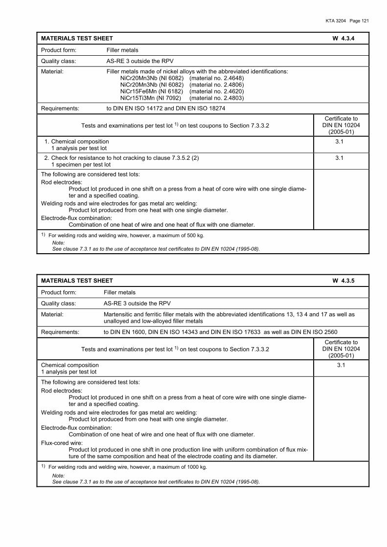
KTA 3204 Page 121
MATERIALS TEST SHEET W 4.3.4
Product form: Filler metals
Quality class: AS-RE 3 outside the RPV
Material: Filler metals made of nickel alloys with the abbreviated identifications: NiCr20Mn3Nb (NI 6082) (material no. 2.4648) NiCr20Mn3Nb (NI 6082) (material no. 2.4806) NiCr15Fe6Mn (NI 6182) (material no. 2.4620) NiCr15Ti3Mn (NI 7092) (material no. 2.4803)
Requirements: to DIN EN ISO 14172 and DIN EN ISO 18274
Tests and examinations per test lot 1) on test coupons to Section 7.3.3.2 Certificate to
DIN EN 10204 (2005-01)
1. Chemical composition 1 analysis per test lot
3.1
2. Check for resistance to hot cracking to clause 7.3.5.2 (2) 1 specimen per test lot
3.1
The following are considered test lots: Rod electrodes:
Product lot produced in one shift on a press from a heat of core wire with one single diame-ter and a specified coating.
Welding rods and wire electrodes for gas metal arc welding: Product lot produced from one heat with one single diameter.
Electrode-flux combination: Combination of one heat of wire and one heat of flux with one diameter.
1) For welding rods and welding wire, however, a maximum of 500 kg. Note: See clause 7.3.1 as to the use of acceptance test certificates to DIN EN 10204 (1995-08).
MATERIALS TEST SHEET W 4.3.5
Product form: Filler metals
Quality class: AS-RE 3 outside the RPV
Material: Martensitic and ferritic filler metals with the abbreviated identifications 13, 13 4 and 17 as well as unalloyed and low-alloyed filler metals
Requirements: to DIN EN 1600, DIN EN ISO 14343 and DIN EN ISO 17633 as well as DIN EN ISO 2560
Tests and examinations per test lot 1) on test coupons to Section 7.3.3.2 Certificate to
DIN EN 10204 (2005-01)
Chemical composition 1 analysis per test lot
3.1
The following are considered test lots: Rod electrodes:
Product lot produced in one shift on a press from a heat of core wire with one single diame-ter and a specified coating.
Welding rods and wire electrodes for gas metal arc welding: Product lot produced from one heat with one single diameter.
Electrode-flux combination: Combination of one heat of wire and one heat of flux with one diameter.
Flux-cored wire: Product lot produced in one shift in one production line with uniform combination of flux mix-ture of the same composition and heat of the electrode coating and its diameter.
1) For welding rods and welding wire, however, a maximum of 1000 kg.
Note: See clause 7.3.1 as to the use of acceptance test certificates to DIN EN 10204 (1995-08).
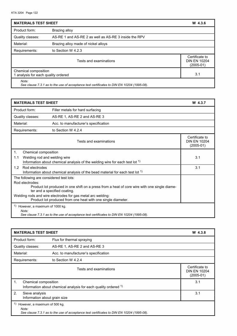
KTA 3204 Page 122
MATERIALS TEST SHEET W 4.3.6
Product form: Brazing alloy
Quality classes: AS-RE 1 and AS-RE 2 as well as AS-RE 3 inside the RPV
Material: Brazing alloy made of nickel alloys
Requirements: to Section W 4.2.3
Tests and examinations Certificate to
DIN EN 10204 (2005-01)
Chemical composition 1 analysis for each quality ordered
3.1
Note: See clause 7.3.1 as to the use of acceptance test certificates to DIN EN 10204 (1995-08).
MATERIALS TEST SHEET W 4.3.7
Product form: Filler metals for hard surfacing
Quality classes: AS-RE 1, AS-RE 2 and AS-RE 3
Material: Acc. to manufacturer�s specification
Requirements: to Section W 4.2.4
Tests and examinations Certificate to
DIN EN 10204 (2005-01)
1. Chemical composition 1.1 Welding rod and welding wire 3.1 Information about chemical analysis of the welding wire for each test lot 1)
1.2 Rod electrodes 3.1 Information about chemical analysis of the bead material for each test lot 1)
The following are considered test lots: Rod electrodes:
Product lot produced in one shift on a press from a heat of core wire with one single diame-ter and a specified coating.
Welding rods and wire electrodes for gas metal arc welding: Product lot produced from one heat with one single diameter.
1) However, a maximum of 1000 kg. Note: See clause 7.3.1 as to the use of acceptance test certificates to DIN EN 10204 (1995-08).
MATERIALS TEST SHEET W 4.3.8
Product form: Flux for thermal spraying
Quality classes: AS-RE 1, AS-RE 2 and AS-RE 3
Material: Acc. to manufacturer�s specification
Requirements: to Section W 4.2.4
Tests and examinations Certificate to DIN EN 10204
(2005-01)
1. Chemical composition 3.1 Information about chemical analysis for each quality ordered 1)
2. Sieve analysis 3.1 Information about grain size 1) However, a maximum of 500 kg.
Note: See clause 7.3.1 as to the use of acceptance test certificates to DIN EN 10204 (1995-08).
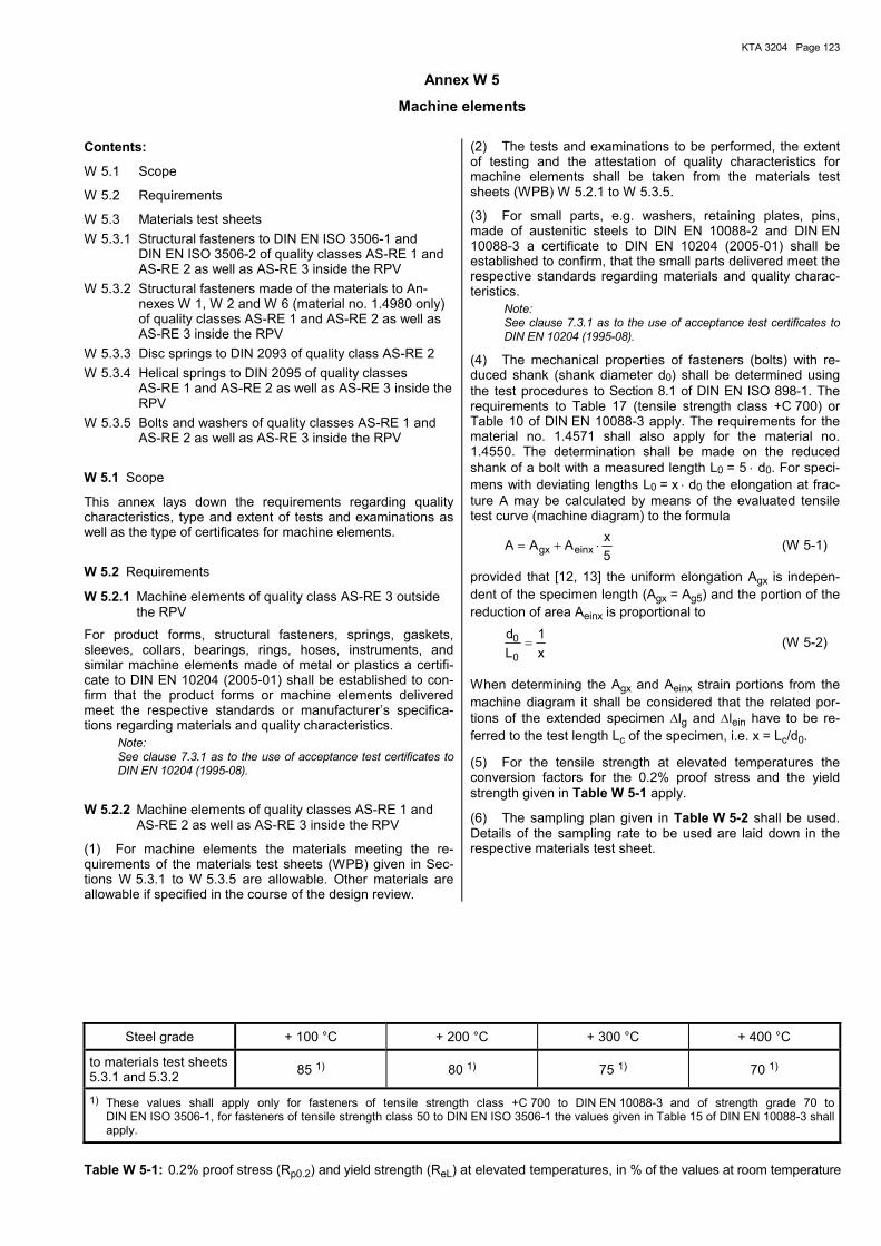
KTA 3204 Page 123
Annex W 5
Machine elements Contents:
W 5.1 Scope
W 5.2 Requirements
W 5.3 Materials test sheets W 5.3.1 Structural fasteners to DIN EN ISO 3506-1 and
DIN EN ISO 3506-2 of quality classes AS-RE 1 and AS-RE 2 as well as AS-RE 3 inside the RPV
W 5.3.2 Structural fasteners made of the materials to An-nexes W 1, W 2 and W 6 (material no. 1.4980 only) of quality classes AS-RE 1 and AS-RE 2 as well as AS-RE 3 inside the RPV
W 5.3.3 Disc springs to DIN 2093 of quality class AS-RE 2 W 5.3.4 Helical springs to DIN 2095 of quality classes
AS-RE 1 and AS-RE 2 as well as AS-RE 3 inside the RPV
W 5.3.5 Bolts and washers of quality classes AS-RE 1 and AS-RE 2 as well as AS-RE 3 inside the RPV
W 5.1 Scope
This annex lays down the requirements regarding quality characteristics, type and extent of tests and examinations as well as the type of certificates for machine elements.
W 5.2 Requirements
W 5.2.1 Machine elements of quality class AS-RE 3 outside the RPV
For product forms, structural fasteners, springs, gaskets, sleeves, collars, bearings, rings, hoses, instruments, and similar machine elements made of metal or plastics a certifi-cate to DIN EN 10204 (2005-01) shall be established to con-firm that the product forms or machine elements delivered meet the respective standards or manufacturer�s specifica-tions regarding materials and quality characteristics.
Note: See clause 7.3.1 as to the use of acceptance test certificates to DIN EN 10204 (1995-08).
W 5.2.2 Machine elements of quality classes AS-RE 1 and AS-RE 2 as well as AS-RE 3 inside the RPV
(1) For machine elements the materials meeting the re-quirements of the materials test sheets (WPB) given in Sec-tions W 5.3.1 to W 5.3.5 are allowable. Other materials are allowable if specified in the course of the design review.
(2) The tests and examinations to be performed, the extent of testing and the attestation of quality characteristics for machine elements shall be taken from the materials test sheets (WPB) W 5.2.1 to W 5.3.5.
(3) For small parts, e.g. washers, retaining plates, pins, made of austenitic steels to DIN EN 10088-2 and DIN EN 10088-3 a certificate to DIN EN 10204 (2005-01) shall be established to confirm, that the small parts delivered meet the respective standards regarding materials and quality charac-teristics.
Note: See clause 7.3.1 as to the use of acceptance test certificates to DIN EN 10204 (1995-08).
(4) The mechanical properties of fasteners (bolts) with re-duced shank (shank diameter d0) shall be determined using the test procedures to Section 8.1 of DIN EN ISO 898-1. The requirements to Table 17 (tensile strength class +C 700) or Table 10 of DIN EN 10088-3 apply. The requirements for the material no. 1.4571 shall also apply for the material no. 1.4550. The determination shall be made on the reduced shank of a bolt with a measured length L0 = 5 ⋅ d0. For speci-mens with deviating lengths L0 = x ⋅ d0 the elongation at frac-ture A may be calculated by means of the evaluated tensile test curve (machine diagram) to the formula
5xAAA einxgx ⋅+= (W 5-1)
provided that [12, 13] the uniform elongation Agx is indepen-dent of the specimen length (Agx = Ag5) and the portion of the reduction of area Aeinx is proportional to
x1
Ld
0
0 = (W 5-2)
When determining the Agx and Aeinx strain portions from the machine diagram it shall be considered that the related por-tions of the extended specimen ∆lg and ∆lein have to be re-ferred to the test length Lc of the specimen, i.e. x = Lc/d0.
(5) For the tensile strength at elevated temperatures the conversion factors for the 0.2% proof stress and the yield strength given in Table W 5-1 apply.
(6) The sampling plan given in Table W 5-2 shall be used. Details of the sampling rate to be used are laid down in the respective materials test sheet.
Steel grade + 100 °C + 200 °C + 300 °C + 400 °C
to materials test sheets 5.3.1 and 5.3.2 85 1) 80 1) 75 1) 70 1)
1) These values shall apply only for fasteners of tensile strength class +C 700 to DIN EN 10088-3 and of strength grade 70 to DIN EN ISO 3506-1, for fasteners of tensile strength class 50 to DIN EN ISO 3506-1 the values given in Table 15 of DIN EN 10088-3 shall apply.
Table W 5-1: 0.2% proof stress (Rp0.2) and yield strength (ReL) at elevated temperatures, in % of the values at room temperature
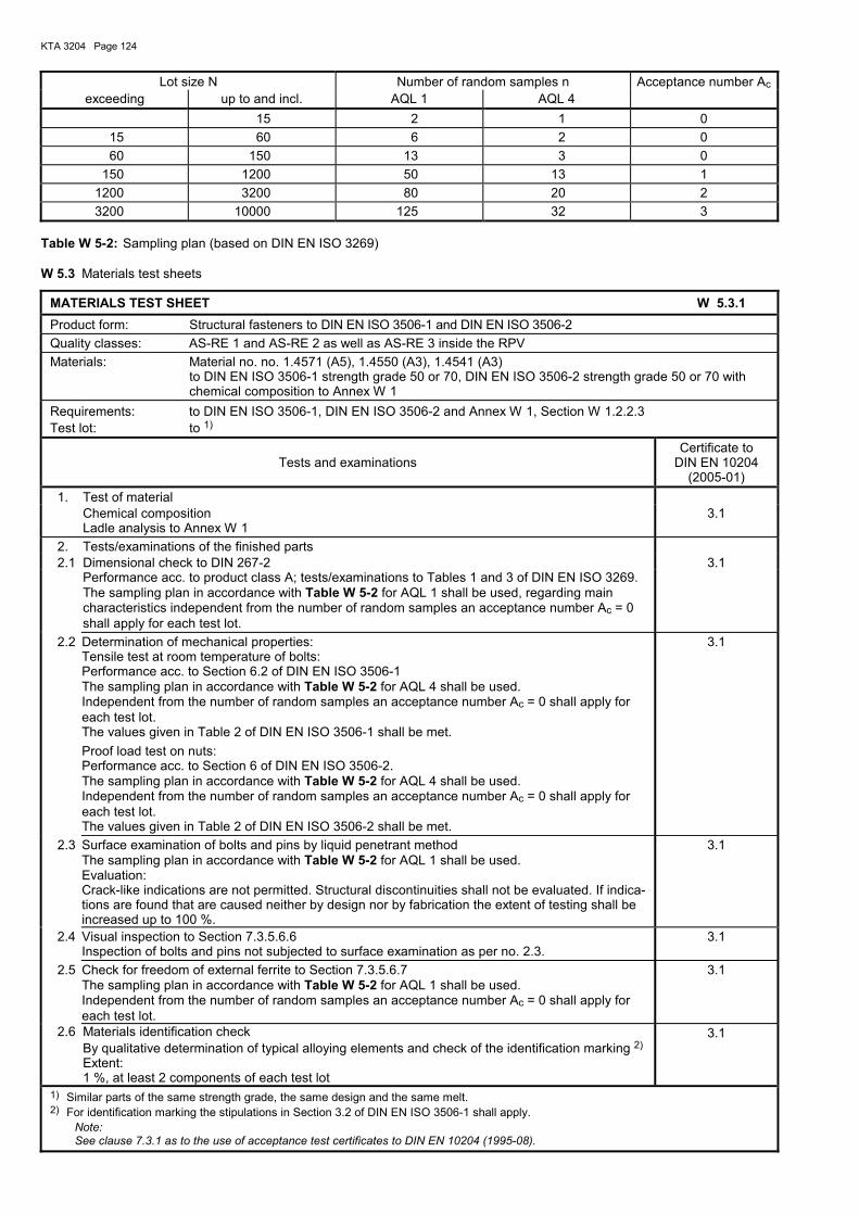
KTA 3204 Page 124
Lot size N Number of random samples n Acceptance number Acexceeding up to and incl. AQL 1 AQL 4
15 2 1 0 15 60 6 2 0 60 150 13 3 0
150 1200 50 13 1 1200 3200 80 20 2 3200 10000 125 32 3
Table W 5-2: Sampling plan (based on DIN EN ISO 3269) W 5.3 Materials test sheets
MATERIALS TEST SHEET W 5.3.1 Product form: Structural fasteners to DIN EN ISO 3506-1 and DIN EN ISO 3506-2 Quality classes: AS-RE 1 and AS-RE 2 as well as AS-RE 3 inside the RPV Materials: Material no. no. 1.4571 (A5), 1.4550 (A3), 1.4541 (A3)
to DIN EN ISO 3506-1 strength grade 50 or 70, DIN EN ISO 3506-2 strength grade 50 or 70 with chemical composition to Annex W 1
Requirements: to DIN EN ISO 3506-1, DIN EN ISO 3506-2 and Annex W 1, Section W 1.2.2.3 Test lot: to 1)
Tests and examinations Certificate to
DIN EN 10204 (2005-01)
1. Test of material Chemical composition Ladle analysis to Annex W 1
3.1
2. Tests/examinations of the finished parts 2.1 Dimensional check to DIN 267-2 3.1 Performance acc. to product class A; tests/examinations to Tables 1 and 3 of DIN EN ISO 3269. The sampling plan in accordance with Table W 5-2 for AQL 1 shall be used, regarding main
characteristics independent from the number of random samples an acceptance number Ac = 0 shall apply for each test lot.
2.2 Determination of mechanical properties: Tensile test at room temperature of bolts: Performance acc. to Section 6.2 of DIN EN ISO 3506-1 The sampling plan in accordance with Table W 5-2 for AQL 4 shall be used. Independent from the number of random samples an acceptance number Ac = 0 shall apply for each test lot. The values given in Table 2 of DIN EN ISO 3506-1 shall be met. Proof load test on nuts: Performance acc. to Section 6 of DIN EN ISO 3506-2. The sampling plan in accordance with Table W 5-2 for AQL 4 shall be used. Independent from the number of random samples an acceptance number Ac = 0 shall apply for each test lot. The values given in Table 2 of DIN EN ISO 3506-2 shall be met.
3.1
2.3 Surface examination of bolts and pins by liquid penetrant method The sampling plan in accordance with Table W 5-2 for AQL 1 shall be used. Evaluation: Crack-like indications are not permitted. Structural discontinuities shall not be evaluated. If indica-tions are found that are caused neither by design nor by fabrication the extent of testing shall be increased up to 100 %.
3.1
2.4 Visual inspection to Section 7.3.5.6.6 Inspection of bolts and pins not subjected to surface examination as per no. 2.3.
3.1
2.5 Check for freedom of external ferrite to Section 7.3.5.6.7 The sampling plan in accordance with Table W 5-2 for AQL 1 shall be used. Independent from the number of random samples an acceptance number Ac = 0 shall apply for each test lot.
3.1
2.6 Materials identification check By qualitative determination of typical alloying elements and check of the identification marking 2) Extent:
1 %, at least 2 components of each test lot
3.1
1) Similar parts of the same strength grade, the same design and the same melt. 2) For identification marking the stipulations in Section 3.2 of DIN EN ISO 3506-1 shall apply.
Note: See clause 7.3.1 as to the use of acceptance test certificates to DIN EN 10204 (1995-08).
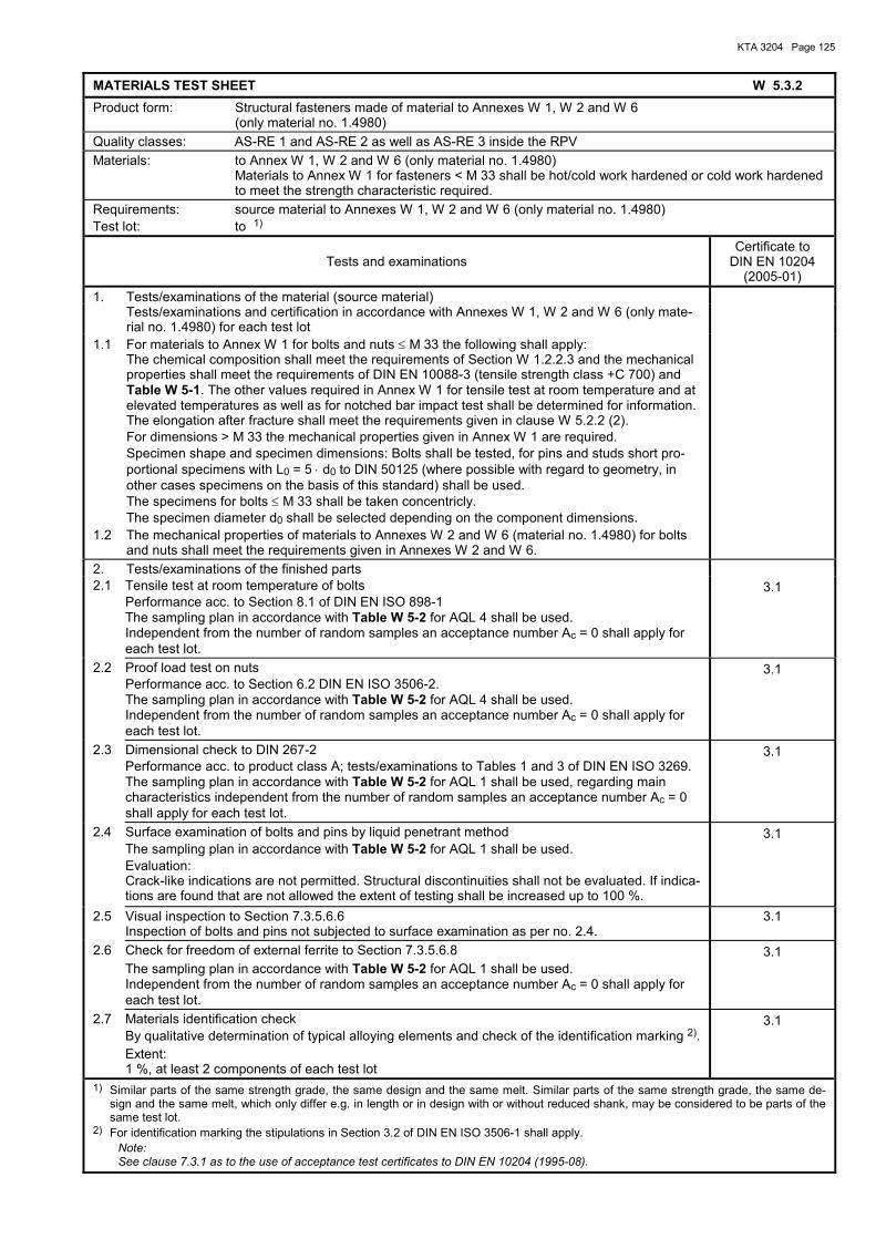
KTA 3204 Page 125
MATERIALS TEST SHEET W 5.3.2 Product form: Structural fasteners made of material to Annexes W 1, W 2 and W 6
(only material no. 1.4980) Quality classes: AS-RE 1 and AS-RE 2 as well as AS-RE 3 inside the RPV Materials: to Annex W 1, W 2 and W 6 (only material no. 1.4980)
Materials to Annex W 1 for fasteners < M 33 shall be hot/cold work hardened or cold work hardened to meet the strength characteristic required.
Requirements: source material to Annexes W 1, W 2 and W 6 (only material no. 1.4980) Test lot: to 1)
Tests and examinations Certificate to
DIN EN 10204 (2005-01)
1. Tests/examinations of the material (source material) Tests/examinations and certification in accordance with Annexes W 1, W 2 and W 6 (only mate-
rial no. 1.4980) for each test lot
1.1 For materials to Annex W 1 for bolts and nuts ≤ M 33 the following shall apply: The chemical composition shall meet the requirements of Section W 1.2.2.3 and the mechanical
properties shall meet the requirements of DIN EN 10088-3 (tensile strength class +C 700) and Table W 5-1. The other values required in Annex W 1 for tensile test at room temperature and at elevated temperatures as well as for notched bar impact test shall be determined for information. The elongation after fracture shall meet the requirements given in clause W 5.2.2 (2).
For dimensions > M 33 the mechanical properties given in Annex W 1 are required. Specimen shape and specimen dimensions: Bolts shall be tested, for pins and studs short pro-
portional specimens with L0 = 5 ⋅ d0 to DIN 50125 (where possible with regard to geometry, in other cases specimens on the basis of this standard) shall be used. The specimens for bolts ≤ M 33 shall be taken concentricly.
The specimen diameter d0 shall be selected depending on the component dimensions.
1.2 The mechanical properties of materials to Annexes W 2 and W 6 (material no. 1.4980) for bolts and nuts shall meet the requirements given in Annexes W 2 and W 6.
2. Tests/examinations of the finished parts 2.1 Tensile test at room temperature of bolts
Performance acc. to Section 8.1 of DIN EN ISO 898-1 The sampling plan in accordance with Table W 5-2 for AQL 4 shall be used. Independent from the number of random samples an acceptance number Ac = 0 shall apply for each test lot.
3.1
2.2 Proof load test on nuts Performance acc. to Section 6.2 DIN EN ISO 3506-2. The sampling plan in accordance with Table W 5-2 for AQL 4 shall be used. Independent from the number of random samples an acceptance number Ac = 0 shall apply for each test lot.
3.1
2.3 Dimensional check to DIN 267-2 Performance acc. to product class A; tests/examinations to Tables 1 and 3 of DIN EN ISO 3269. The sampling plan in accordance with Table W 5-2 for AQL 1 shall be used, regarding main characteristics independent from the number of random samples an acceptance number Ac = 0 shall apply for each test lot.
3.1
2.4 Surface examination of bolts and pins by liquid penetrant method The sampling plan in accordance with Table W 5-2 for AQL 1 shall be used. Evaluation: Crack-like indications are not permitted. Structural discontinuities shall not be evaluated. If indica-tions are found that are not allowed the extent of testing shall be increased up to 100 %.
3.1
2.5 Visual inspection to Section 7.3.5.6.6 Inspection of bolts and pins not subjected to surface examination as per no. 2.4.
3.1
2.6 Check for freedom of external ferrite to Section 7.3.5.6.8 The sampling plan in accordance with Table W 5-2 for AQL 1 shall be used. Independent from the number of random samples an acceptance number Ac = 0 shall apply for each test lot.
3.1
2.7 Materials identification check By qualitative determination of typical alloying elements and check of the identification marking 2). Extent: 1 %, at least 2 components of each test lot
3.1
1) Similar parts of the same strength grade, the same design and the same melt. Similar parts of the same strength grade, the same de-sign and the same melt, which only differ e.g. in length or in design with or without reduced shank, may be considered to be parts of the same test lot.
2) For identification marking the stipulations in Section 3.2 of DIN EN ISO 3506-1 shall apply. Note: See clause 7.3.1 as to the use of acceptance test certificates to DIN EN 10204 (1995-08).
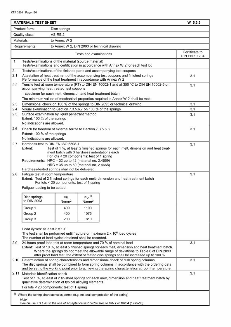
KTA 3204 Page 126
MATERIALS TEST SHEET W 5.3.3
Product form: Disc springs Quality class: AS-RE 2 Materials: to Annex W 2
Requirements: to Annex W 2, DIN 2093 or technical drawing
Tests and examinations Certificate to DIN EN 10 204
1. Tests/examinations of the material (source material) Tests/examinations and certification in accordance with Annex W 2 for each test lot
2. Tests/examinations of the finished parts and accompanying test coupons 2.1 Attestation of heat treatment of the accompanying test coupons and finished springs Performance of the heat treatment in accordance with Annex W 2
3.1
2.2 Tensile test at room temperature (RT) to DIN EN 10002-1 and at 350 °C to DIN EN 10002-5 on accompanying heat treated test coupons 1 specimen for each melt, dimension and heat treatment batch. The minimum values of mechanical properties required in Annex W 2 shall be met.
3.1
2.3 Dimensional check on 100 % of the springs to DIN 2093 or technical drawing 3.1 2.4 Visual examination to Section 7.3.5.6.7 on 100 % of the springs 3.1 2.5 Surface examination by liquid penetrant method
Extent: 100 % of the springs No indications are allowed.
3.1
2.6 Check for freedom of external ferrite to Section 7.3.5.6.8 Extent: 100 % of the springs No indications are allowed.
3.1
2.7 Hardness test to DIN EN ISO 6508-1 Extent: Test of 1 %, at least 2 finished springs for each melt, dimension and heat treat-
ment batch with 3 hardness indentations each For lots < 20 components: test of 1 spring
Requirements: HRC = 32 up to 42 (material no. 2.4669) HRC = 35 up to 50 (material no. 2.4668) Hardness-tested springs shall not be delivered
3.1
2.8 Fatigue test at room temperature Extent: Test of 2 finished springs for each melt, dimension and heat treatment batch
For lots < 20 components: test of 1 spring Fatigue loading to be setted:
3.1
Disc springs to DIN 2093
σU N/mm2
σO 1)
N/mm2
Group 1 400 1100
Group 2 400 1075
Group 3 200 810 Load cycles: at least 2 x 10⁵
The test shall be performed until fracture or maximum 2 x 10⁶ load cycles The number of load cycles obtained shall be recorded.
2.9 24-hours proof load test at room temperature and 70 % of nominal load Extent: Test of 10 %, at least 5 finished springs for each melt, dimension and heat treatment batch.
Where the springs do not meet the allowable range of deviations to Table 6 of DIN 2093 after proof load test, the extent of tested disc springs shall be increased up to 100 %.
3.1
2.10 Determination of spring characteristics and dimensional check of disk spring columns The disc springs shall be combined to form spring columns in accordance with the ordering data and be set to the working point prior to achieving the spring characteristics at room temperature.
3.1
2.11 Materials identification check Test of 1 %, at least of 2 finished springs for each melt, dimension and heat treatment batch by qualitative determination of typical alloying elements For lots < 20 components: test of 1 spring
3.1
1) Where the spring characteristics permit (e.g. no total compression of the spring) Note: See clause 7.3.1 as to the use of acceptance test certificates to DIN EN 10204 (1995-08).
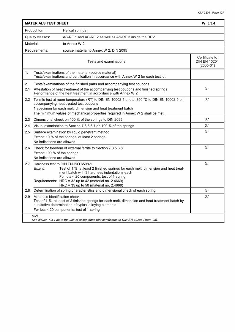
KTA 3204 Page 127
MATERIALS TEST SHEET W 5.3.4
Product form: Helical springs
Quality classes: AS-RE 1 and AS-RE 2 as well as AS-RE 3 inside the RPV
Materials: to Annex W 2
Requirements: source material to Annex W 2, DIN 2095
Tests and examinations Certificate to
DIN EN 10204 (2005-01)
1. Tests/examinations of the material (source material) Tests/examinations and certification in accordance with Annex W 2 for each test lot
2. Tests/examinations of the finished parts and accompanying test coupons
2.1 Attestation of heat treatment of the accompanying test coupons and finished springs Performance of the heat treatment in accordance with Annex W 2
3.1
2.2 Tensile test at room temperature (RT) to DIN EN 10002-1 and at 350 °C to DIN EN 10002-5 on accompanying heat treated test coupons 1 specimen for each melt, dimension and heat treatment batch The minimum values of mechanical properties required in Annex W 2 shall be met.
3.1
2.3 Dimensional check on 100 % of the springs to DIN 2095 3.1
2.4 Visual examination to Section 7.3.5.6.7 on 100 % of the springs 3.1
2.5 Surface examination by liquid penetrant method Extent: 10 % of the springs, at least 2 springs No indications are allowed.
3.1
2.6 Check for freedom of external ferrite to Section 7.3.5.6.8 Extent: 100 % of the springs. No indications are allowed.
3.1
2.7 Hardness test to DIN EN ISO 6508-1 Extent: Test of 1 %, at least 2 finished springs for each melt, dimension and heat treat-
ment batch with 3 hardness indentations each For lots < 20 components: test of 1 spring
Requirements: HRC = 32 up to 42 (material no. 2.4669) HRC = 35 up to 50 (material no. 2.4668)
3.1
2.8 Determination of spring characteristics and dimensional check of each spring 3.1
2.9 Materials identification check Test of 1 %, at least of 2 finished springs for each melt, dimension and heat treatment batch by qualitative determination of typical alloying elements For lots < 20 components: test of 1 spring
3.1
Note: See clause 7.3.1 as to the use of acceptance test certificates to DIN EN 10204 (1995-08).
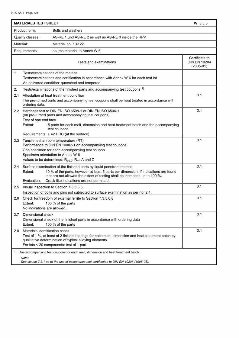
KTA 3204 Page 128
MATERIALS TEST SHEET W 5.3.5
Product form: Bolts and washers
Quality classes: AS-RE 1 und AS-RE 2 as well as AS-RE 3 inside the RPV
Material: Material no. 1.4122
Requirements: source material to Annex W 6
Tests and examinations Certificate to
DIN EN 10204 (2005-01)
1. Tests/examinations of the material Tests/examinations and certification in accordance with Annex W 6 for each test lot As-delivered condition: quenched and tempered
2. Tests/examinations of the finished parts and accompanying test coupons 1)
2.1 Attestation of heat treatment condition The pre-turned parts and accompanying test coupons shall be heat treated in accordance with ordering data.
3.1
2.2 Hardness test to DIN EN ISO 6508-1 or DIN EN ISO 6506-1 (on pre-turned parts and accompanying test coupons) Test of one end face Extent: 5 parts for each melt, dimension and heat treatment batch and the accompanying
test coupons Requirements: ≥ 42 HRC (at the surface)
3.1
2.3 Tensile test at room temperature (RT) Performance to DIN EN 10002-1 on accompanying test coupons. One specimen for each accompanying test coupon Specimen orientation to Annex W 6 Values to be determined: Rp0.2; Rm; A and Z
3.1
2.4 Surface examination of the finished parts by liquid penetrant method Extent: 10 % of the parts, however at least 5 parts per dimension. If indications are found
that are not allowed the extent of testing shall be increased up to 100 %. Evaluation: Crack-like indications are not permitted.
3.1
2.5 Visual inspection to Section 7.3.5.6.6 Inspection of bolts and pins not subjected to surface examination as per no. 2.4.
3.1
2.6 Check for freedom of external ferrite to Section 7.3.5.6.8 Extent: 100 % of the parts No indications are allowed.
3.1
2.7 Dimensional check Dimensional check of the finished parts in accordance with ordering data Extent: 100 % of the parts
3.1
2.8 Materials identification check Test of 1 %, at least of 2 finished springs for each melt, dimension and heat treatment batch by qualitative determination of typical alloying elements For lots < 20 components: test of 1 part
3.1
1) One accompanying test coupons for each melt, dimension and heat treatment batch.
Note: See clause 7.3.1 as to the use of acceptance test certificates to DIN EN 10204 (1995-08).
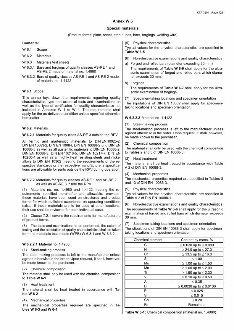
KTA 3204 Page 129
Annex W 6
Special materials (Product forms: plate, sheet, strip, tubes, bars, forgings, welding wire)
Contents:
W 6.1 Scope
W 6.2 Materials
W 6.3 Materials test sheets W 6.3.1 Bars and forgings of quality classes AS-RE 1 and
AS-RE 2 made of material no. 1.4980 W 6.3.2 Bars of quality classes AS-RE 1 and AS-RE 2 made
of material no. 1.4122
W 6.1 Scope
This annex lays down the requirements regarding quality characteristics, type and extent of tests and examinations as well as the type of certificates for quality characteristics not included in Annexes W 1 to W 4. The requirements shall apply for the as-delivered condition unless specified otherwise hereinafter.
W 6.2 Materials
W 6.2.1 Materials for quality class AS-RE 3 outside the RPV
All ferritic and martensitic materials to DIN EN 10025-2, DIN EN 10083-2, DIN EN 10084, DIN EN 10088-2 und DIN EN 10088-3 as well as all austenitic materials to DIN EN 10088-2, DIN EN 10088-3, DIN EN 10216-5, DIN EN 10217-7, DIN EN 10250-4 as well as all highly heat resisting steels and nickel alloys to DIN EN 10302 meeting the requirements of the re-spective standards or the respective manufacturer�s specifica-tions are allowable for parts outside the RPV during operation.
W 6.2.2 Materials for quality classes AS-RE 1 and AS-RE 2 as well as AS-RE 3 inside the RPV
(1) Materials no. no. 1.4980 and 1.4122 meeting the re-quirements specified hereinafter are allowable, provided, these materials have been used on structures and product forms for which sufficient experience on operating conditions exists. If these materials are to be used at other locations, their use shall be reviewed for each individual case.
(2) Clause 7.2.1 covers the requirements for manufacturers of product forms.
(3) The tests and examinations to be performed, the extent of testing and the attestation of quality characteristics shall be taken from the materials test sheets (WPB) W 6.3.1 and W 6.3.2.
W 6.2.2.1 Material no. 1.4980 (1) Steel-making process The steel-making processs is left to the manufacturer unless agreed otherwise in the order. Upon request, it shall, however, be made known to the purchaser.
(2) Chemical composition The material shall only be used with the chemical composition to Table W 6-1.
(3) Heat treatment The material shall be heat treated in accordance with Ta-ble W 6-2.
(4) Mechanical properties The mechanical properties required are specified in Ta-bles W 6-3 and W 6-4.
(5) Physical characteristics Typical values for the physical characteristics are specified in Table W 6-5.
(6) Non-destructive examinations and quality characteristics a) Forged und rolled bars (diameter exceeding 30 mm) The requirements of Table W 6-6 shall apply for the ultra-
sonic examination of forged and rolled bars which diame-ter exceeds 30 mm.
b) Forgings The requirements of Table W 6-7 shall apply for the ultra-
sonic examination of forgings.
(7) Specimen-taking locations and specimen orientation The stipulations of DIN EN 10302 shall apply for specimen-taking locations and specimen orientation.
W 6.2.2.2 Material no. 1.4122
(1) Steel-making process The steel-making processs is left to the manufacturer unless agreed otherwise in the order. Upon request, it shall, however, be made known to the purchaser.
(2) Chemical composition The material shall only be used with the chemical composition to Tables 2 and 5 of DIN EN 10088-3.
(3) Heat treatment The material shall be heat treated in accordance with Table A 2 of DIN EN 10088-3.
(4) Mechanical properties The mechanical properties required are specified in Tables 8 and 13 of DIN EN 10088-3.
(5) Physical characteristics Typical values for the physical characteristics are specified in Table A 2 of DIN EN 10088-1.
(6) Non-destructive examinations and quality characteristics The requirements of Table W 6-6 shall apply for the ultrasonic examination of forged and rolled bars which diameter exceeds 30 mm.
(7) Specimen-taking locations and specimen orientation The stipulations of DIN EN 10088-3 shall apply for specimen-taking locations and specimen orientation.
Chemical element Content by mass, % C ≥ 0.030 up to ≤ 0.080 Ni ≥ 24.0 up to ≤ 27.0 Cr ≥ 13.5 up to ≤ 16.0 Si ≤ 1.00 Mo ≥ 1.00 up to ≤ 1.50 Mn ≥ 1.00 up to ≤ 2.00 Ti ≥ 1.90 up to ≤ 2.30 V ≥ 0.10 up to ≤ 0.50 Al ≤ 0.35 B ≥ 0.0030 up to ≤ 0.0100 P ≤ 0.025 S ≤ 0.015 Co ≤ 0.20 Fe Remainder
Table W 6-1: Chemical composition (material no. 1.4980)
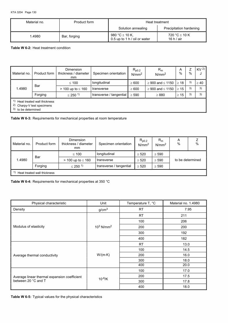
KTA 3204 Page 130
Material no. Product form Heat treatment
Solution annealing Precipitation hardening
1.4980 Bar, forging 980 °C ± 10 K, 0.5 up to 1 h / oil or water
720 °C ± 10 K 16 h / air
Table W 6-2: Heat treatment condition
Material no. Product form Dimension
thickness / diameter mm
Specimen orientation Rp0.2
N/mm2 Rm
N/mm2 A %
Z %
KV 2)
J
≤ 100 longitudinal ≥ 600 ≥ 900 and ≤ 1150 ≥ 18 3) ≥ 40
1.4980
Bar
> 100 up to ≤ 160 transverse ≥ 600 ≥ 900 and ≤ 1150 ≥ 15 3) 3)
Forging ≤ 250 1) transverse / tangential ≥ 590 ≥ 880 ≥ 15 3) 3) 1) Heat treated wall thickness 2) Charpy-V test specimens 3) to be determined
Table W 6-3: Requirements for mechanical properties at room temperature
Material no. Product form Dimension
thickness / diameter mm
Specimen orientation Rp0.2
N/mm2 Rm
N/mm2 A %
Z %
≤ 100 longitudinal ≥ 520 ≥ 590
1.4980
Bar
> 100 up to ≤ 160 transverse ≥ 520 ≥ 590 to be determined
Forging ≤ 250 1) transverse / tangential ≥ 520 ≥ 590
1) Heat treated wall thickness
Table W 6-4: Requirements for mechanical properties at 350 °C
Physical characteristic Unit Temperature T, °C Material no. 1.4980
Density g/cm3 RT 7.95
RT 211
100 206
200 200
300 192
Modulus of elasticity
103 N/mm2
400 182
RT 13.0 100 14.5 200 16.0 300 18.0
Average thermal conductivity
W/(m⋅K)
400 20.0
100 17.0 200 17.5 300 17.8
Average linear thermal expansion coefficient between 20 °C and T
10-6/K
400 18.0
Table W 6-5: Typical values for the physical characteristics
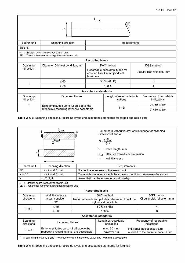
KTA 3204 Page 131
1
D
Search unit Scanning direction Requirements
SE or N 1
N : Straight beam transceiver search unit SE : Transmitter-receiver straight beam search unit
Recording levels
Scanning direction
Diameter D in test condition, mm DAC method Recordable echo amplitudes ref-erenced to a 4 mm cylindrical bore hole
DGS method
Circular disk reflector, mm
≤ 60 50 % (-6 dB) 3 1 > 60 100 % 4
Acceptance standards
Scanning direction
Echo amplitudes Length of recordable indi-cations
Frequency of recordable indications
D ≤ 60: ≤ 3/m 1 Echo amplitudes up to 12 dB above the respective recording level are acceptable
1 x D
D > 60: ≤ 5/m
Table W 6-6: Scanning directions, recording levels und acceptance standards for forged and rolled bars
43
2
1
s
Sound path without lateral wall influence for scanning directions 3 and 4:
λ⋅⋅
=2DsS eff
λ : wave length, mm
Deff : effective transducer dimension s : wall thickness
Search unit Scanning direction Requirements SE 1 or 2 and 3 or 4 S < as the scan area of the search unit N + SE 1 or 2 and 3 or 4 Transmitter-receiver straight beam search unit for the near-surface area N 1, 2, 3, 4 Areas that can be evaluated shall overlap N : Straight beam transceiver search unit SE : Transmitter-receiver straight beam search unit
Recording levels
Scanning directions
Wall thickness s in test condition,
mm
DAC method Recordable echo amplitudes referenced to a 4 mm
cylindrical bore hole
DGS method Circular disk reflector, mm
≤ 60 50 % (-6 dB) 4 1 to 4
> 60 100 % 6
Acceptance standards
Scanning directions Echo amplitudes Length of recordable
indications Frequency of recordable
indications
1 to 4 Echo amplitudes up to 12 dB above the respective recording level are acceptable
max. 50 mm, however ≤ s
individual indications: ≤ 5/m referred to the entire surface: ≤ 3/m
1) In scanning directions 3 and 4 no reflectors with dimensions exceeding 10 mm are acceptable.
Table W 6-7: Scanning directions, recording levels and acceptance standards for forgings
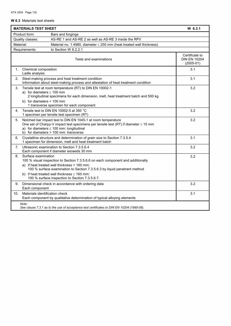
KTA 3204 Page 132
W 6.3 Materials test sheets
MATERIALS TEST SHEET W 6.3.1 Product form: Bars and forgings Quality classes: AS-RE 1 and AS-RE 2 as well as AS-RE 3 inside the RPV Material: Material no. 1.4980, diameter ≤ 250 mm (heat treated wall thickness) Requirements: to Section W 6.2.2.1
Tests and examinations Certificate to
DIN EN 10204 (2005-01)
1. Chemical composition Ladle analysis
3.1
2. Steel-making process and heat treatment condition Information about steel-making process and attestation of heat treatment condition
3.1
3. Tensile test at room temperature (RT) to DIN EN 10002-1 a) for diameters ≤ 100 mm 2 longitudinal specimens for each dimension, melt, heat treatment batch and 500 kg b) for diameters > 100 mm 1 transverse specimen for each component
3.2
4. Tensile test to DIN EN 10002-5 at 350 °C 1 specimen per tensile test specimen (RT)
3.2
5. Notched bar impact test to DIN EN 1045-1 at room temperature One set of Charpy-V impact test specimens per tensile test (RT) if diameter ≥ 15 mm a) for diameters ≤ 100 mm: longitudinal b) for diameters > 100 mm: transverse
3.2
6. Crystalline structure and determination of grain size to Section 7.3.5.4 1 specimen for dimension, melt and heat treatment batch
3.1
7. Ultrasonic examination to Section 7.3.5.6.4 Each component if diameter exceeds 30 mm
3.2
8. Surface examination 100 % visual inspection to Section 7.3.5.6.6 on each component and additionally
3.2
a) if heat treated wall thickness > 160 mm: 100 % surface examination to Section 7.3.5.6.3 by liquid penetrant method b) if heat treated wall thickness ≤ 160 mm: 100 % surface inspection to Section 7.3.5.6.7.
9. Dimensional check in accordance with ordering data Each component
3.2
10. Materials identification check Each component by qualitative determination of typical alloying elements
3.1
Note: See clause 7.3.1 as to the use of acceptance test certificates to DIN EN 10204 (1995-08).
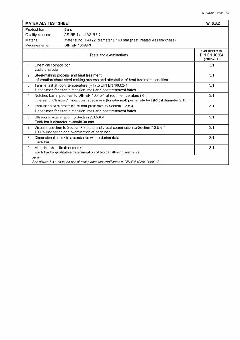
KTA 3204 Page 133
MATERIALS TEST SHEET W 6.3.2 Product form: Bars Quality classes: AS-RE 1 and AS-RE 2 Material: Material no. 1.4122, diameter ≤ 160 mm (heat treated wall thickness) Requirements: DIN EN 10088-3
Tests and examinations Certificate to
DIN EN 10204 (2005-01)
1. Chemical composition Ladle analysis
3.1
2. Steel-making process and heat treatment Information about steel-making process and attestation of heat treatment condition
3.1
3. Tensile test at room temperature (RT) to DIN EN 10002-1 1 specimen for each dimension, melt and heat treatment batch
3.1
4. Notched bar impact test to DIN EN 10045-1 at room temperature (RT) One set of Charpy-V impact test specimens (longitudinal) per tensile test (RT) if diameter ≥ 15 mm
3.1
5. Evaluation of microstructure and grain size to Section 7.3.5.4 1 specimen for each dimension, melt and heat treatment batch
3.1
6. Ultrasonic examination to Section 7.3.5.6.4 Each bar if diameter exceeds 30 mm
3.1
7. Visual inspection to Section 7.3.5.6.6 and visual examination to Section 7.3.5.6.7 100 % inspection and examination of each bar
3.1
8. Dimensional check in accordance with ordering data Each bar
3.1
9. Materials identification check Each bar by qualitative determination of typical alloying elements
3.1
Note: See clause 7.3.1 as to the use of acceptance test certificates to DIN EN 10204 (1995-08).
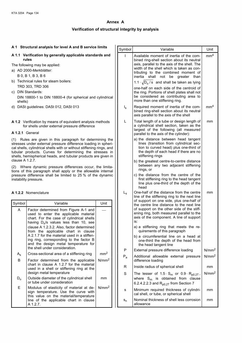
KTA 3204 Page 134
Annex A
Verification of structural integrity by analysis
A 1 Structural analysis for level A and B service limits
A 1.1 Verification by generally applicable standards and rules
The following may be applied: a) AD 2000-Merkblätter: B 0, B 1, B 3, B 6 b) Technical rules for steam boilers: TRD 303, TRD 306 c) DIN Standards: DIN 18800-1 to DIN 18800-4 (for spherical and cylindrical
shells) d) DASt guidelines: DASt 012, DASt 013
A 1.2 Verification by means of equivalent analysis methods for shells under external pressure difference
A 1.2.1 General
(1) Rules are given in this paragraph for determining the stresses under external pressure difference loading in spheri-cal shells, cylindrical shells with or without stiffening rings, and tubular products. Curves for determining the stresses in shells, hemispherical heads, and tubular products are given in clause A 1.2.7.
(2) Where dynamic pressure differences occur, the limita-tions of this paragraph shall apply or the allowable internal pressure difference shall be limited to 25 % of the dynamic instability pressure.
A 1.2.2 Nomenclature
Symbol Variable Unit
A Factor determined from Figure A-1 and used to enter the applicable material chart. For the case of cylindrical shells having Do/s values less than 10, see clause A 1.2.3.2. Also, factor determined from the applicable chart in clause A 2.1.7 for the material used in a stiffen-ing ring, corresponding to the factor B and the design metal temperature for the shell under consideration.
As Cross-sectional area of a stiffening ring mm2
B Factor determined from the applicable chart in clause A 1.2.7 for the material used in a shell or stiffening ring at the design metal temperature
N/mm2
Do Outside diameter of the cylindrical shell or tube under consideration
mm
E
Modulus of elasticity of material at de-sign temperature. Use the curve with this value on the material/temperature line of the applicable chart in clause A 1.2.7.
N/mm2
Symbol Variable Unit
I Available moment of inertia of the com-bined ring-shell section about its neutral axis, parallel to the axis of the shell. The width of the shell which is taken as con-tributing to the combined moment of inertia shall not be greater than 1.1 ⋅ s/Do and shall be taken as lying one-half on each side of the centroid of the ring. Portions of shell plates shall not be considered as contributing area to more than one stiffening ring.
mm4
Is Required moment of inertia of the com-bined ring-shell section about its neutral axis parallel to the axis of the shell
mm4
L Total length of a tube or design length of a cylindrical shell section, taken as the largest of the following (all measured parallel to the axis of the cylinder): a) the distance between head tangent
lines (transition from cylindrical sec-tion to curved head) plus one-third of the depth of each head if there are no stiffening rings
b) the greatest centre-to-centre distance between any two adjacent stiffening rings, or
c) the distance from the centre of the first stiffening ring to the head tangent line plus one-third of the depth of the head
mm
Ls One-half of the distance from the centre line of the stiffening ring to the next line of support on one side, plus one-half of the centre line distance to the next line of support on the other side of the stiff-ening ring, both measured parallel to the axis of the component. A line of support is: a) a stiffening ring that meets the re-
quirements of this paragraph b) a circumferential line on a head at
one-third the depth of the head from the head tangent line
mm
P External pressure difference loading N/mm2 Pa Additional allowable external pressure
difference loading N/mm2
R Inside radius of spherical shell mm
S The lesser of 1.5 ⋅ Sm or 0.9 ⋅ Rp0.2T , where Sm is obtained from clause 6.2.4.2.2.3 and Rp0,2T from Section 7
N/mm2
s Minimum required thickness of cylindri-cal shell, or tube, or spherical shell
mm
sn Nominal thickness of shell less corrosion allowance
mm
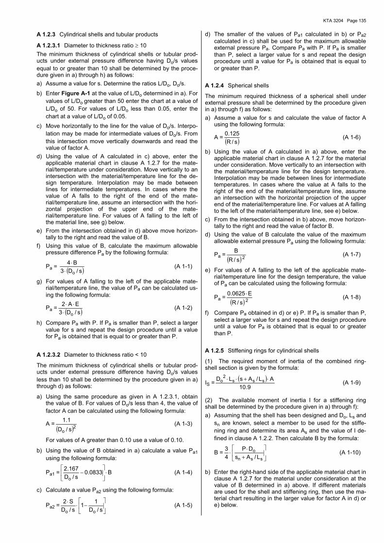
KTA 3204 Page 135
A 1.2.3 Cylindrical shells and tubular products
A 1.2.3.1 Diameter to thickness ratio ≥ 10 The minimum thickness of cylindrical shells or tubular prod-ucts under external pressure difference having Do/s values equal to or greater than 10 shall be determined by the proce-dure given in a) through h) as follows: a) Assume a value for s. Determine the ratios L/Do, Do/s.
b) Enter Figure A-1 at the value of L/Do determined in a). For values of L/Do greater than 50 enter the chart at a value of L/Do of 50. For values of L/Do less than 0.05, enter the chart at a value of L/Do of 0.05.
c) Move horizontally to the line for the value of Do/s. Interpo-lation may be made for intermediate values of Do/s. From this intersection move vertically downwards and read the value of factor A.
d) Using the value of A calculated in c) above, enter the applicable material chart in clause A 1.2.7 for the mate-rial/temperature under consideration. Move vertically to an intersection with the material/temperature line for the de-sign temperature. Interpolation may be made between lines for intermediate temperatures. In cases where the value of A falls to the right of the end of the mate-rial/temperature line, assume an intersection with the hori-zontal projection of the upper end of the mate-rial/temperature line. For values of A falling to the left of the material line, see g) below.
e) From the intersection obtained in d) above move horizon-tally to the right and read the value of B.
f) Using this value of B, calculate the maximum allowable pressure difference Pa by the following formula:
Pa = ( )s/D3B4
o⋅⋅ (A 1-1)
g) For values of A falling to the left of the applicable mate-rial/temperature line, the value of Pa can be calculated us-ing the following formula:
Pa = ( )s/D3EA2
o⋅⋅⋅ (A 1-2)
h) Compare Pa with P. If Pa is smaller than P, select a larger value for s and repeat the design procedure until a value for Pa is obtained that is equal to or greater than P.
A 1.2.3.2 Diameter to thickness ratio < 10
The minimum thickness of cylindrical shells or tubular prod-ucts under external pressure difference having Do/s values less than 10 shall be determined by the procedure given in a) through d) as follows:
a) Using the same procedure as given in A 1.2.3.1, obtain the value of B. For values of Do/s less than 4, the value of factor A can be calculated using the following formula:
A =( )2o s/D
1.1 (A 1-3)
For values of A greater than 0.10 use a value of 0.10.
b) Using the value of B obtained in a) calculate a value Pa1 using the following formula:
Pa1 = B0833.0s/D
167.2
o⋅
− (A 1-4)
c) Calculate a value Pa2 using the following formula:
Pa2 =
−⋅
⋅s/D
11s/D
S2
oo (A 1-5)
d) The smaller of the values of Pa1 calculated in b) or Pa2 calculated in c) shall be used for the maximum allowable external pressure Pa. Compare Pa with P. If Pa is smaller than P, select a larger value for s and repeat the design procedure until a value for Pa is obtained that is equal to or greater than P.
A 1.2.4 Spherical shells
The minimum required thickness of a spherical shell under external pressure shall be determined by the procedure given in a) through f) as follows: a) Assume a value for s and calculate the value of factor A
using the following formula:
A = ( )s/R125.0 (A 1-6)
b) Using the value of A calculated in a) above, enter the applicable material chart in clause A 1.2.7 for the material under consideration. Move vertically to an intersection with the material/temperature line for the design temperature. Interpolation may be made between lines for intermediate temperatures. In cases where the value at A falls to the right of the end of the material/temperature line, assume an intersection with the horizontal projection of the upper end of the material/temperature line. For values at A falling to the left of the material/temperature line, see e) below.
c) From the intersection obtained in b) above, move horizon-tally to the right and read the value of factor B.
d) Using the value of B calculate the value of the maximum allowable external pressure Pa using the following formula:
Pa =( ) 2s/R
B (A 1-7)
e) For values of A falling to the left of the applicable mate-rial/temperature line for the design temperature, the value of Pa can be calculated using the following formula:
Pa =( ) 2s/R
E0625.0 ⋅ (A 1-8)
f) Compare Pa obtained in d) or e) P. If Pa is smaller than P, select a larger value for s and repeat the design procedure until a value for Pa is obtained that is equal to or greater than P.
A 1.2.5 Stiffening rings for cylindrical shells
(1) The required moment of inertia of the combined ring-shell section is given by the formula:
IS = ( )9.10
AL/AsLD sss2
o ⋅+⋅⋅ (A 1-9)
(2) The available moment of inertia I for a stiffening ring shall be determined by the procedure given in a) through f): a) Assuming that the shell has been designed and Do, Ls and
sn are known, select a member to be used for the stiffe-ning ring and determine its area As and the value of I de-fined in clause A 1.2.2. Then calculate B by the formula:
B =
+⋅
⋅ssn
oL/As
DP43 (A 1-10)
b) Enter the right-hand side of the applicable material chart in clause A 1.2.7 for the material under consideration at the value of B determined in a) above. If different materials are used for the shell and stiffening ring, then use the ma-terial chart resulting in the larger value for factor A in d) or e) below.
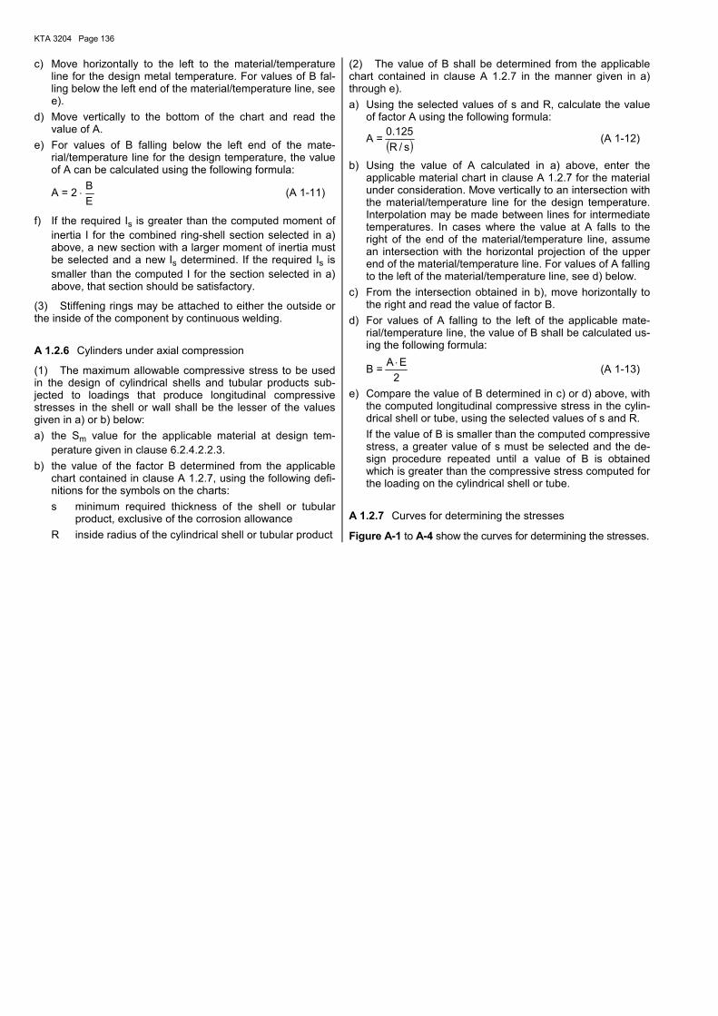
KTA 3204 Page 136
c) Move horizontally to the left to the material/temperature line for the design metal temperature. For values of B fal-ling below the left end of the material/temperature line, see e).
d) Move vertically to the bottom of the chart and read the value of A.
e) For values of B falling below the left end of the mate-rial/temperature line for the design temperature, the value of A can be calculated using the following formula:
A = 2 ⋅EB (A 1-11)
f) If the required Is is greater than the computed moment of inertia I for the combined ring-shell section selected in a) above, a new section with a larger moment of inertia must be selected and a new Is determined. If the required Is is smaller than the computed I for the section selected in a) above, that section should be satisfactory.
(3) Stiffening rings may be attached to either the outside or the inside of the component by continuous welding.
A 1.2.6 Cylinders under axial compression
(1) The maximum allowable compressive stress to be used in the design of cylindrical shells and tubular products sub-jected to loadings that produce longitudinal compressive stresses in the shell or wall shall be the lesser of the values given in a) or b) below: a) the Sm value for the applicable material at design tem-
perature given in clause 6.2.4.2.2.3. b) the value of the factor B determined from the applicable
chart contained in clause A 1.2.7, using the following defi-nitions for the symbols on the charts:
s minimum required thickness of the shell or tubular product, exclusive of the corrosion allowance
R inside radius of the cylindrical shell or tubular product
(2) The value of B shall be determined from the applicable chart contained in clause A 1.2.7 in the manner given in a) through e). a) Using the selected values of s and R, calculate the value
of factor A using the following formula:
A = ( )s/R125.0 (A 1-12)
b) Using the value of A calculated in a) above, enter the applicable material chart in clause A 1.2.7 for the material under consideration. Move vertically to an intersection with the material/temperature line for the design temperature. Interpolation may be made between lines for intermediate temperatures. In cases where the value at A falls to the right of the end of the material/temperature line, assume an intersection with the horizontal projection of the upper end of the material/temperature line. For values of A falling to the left of the material/temperature line, see d) below.
c) From the intersection obtained in b), move horizontally to the right and read the value of factor B.
d) For values of A falling to the left of the applicable mate-rial/temperature line, the value of B shall be calculated us-ing the following formula:
B =2EA ⋅ (A 1-13)
e) Compare the value of B determined in c) or d) above, with the computed longitudinal compressive stress in the cylin-drical shell or tube, using the selected values of s and R.
If the value of B is smaller than the computed compressive stress, a greater value of s must be selected and the de-sign procedure repeated until a value of B is obtained which is greater than the compressive stress computed for the loading on the cylindrical shell or tube.
A 1.2.7 Curves for determining the stresses
Figure A-1 to A-4 show the curves for determining the stresses.
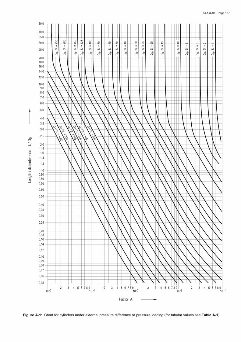
KTA 3204 Page 137
00 0000
0
0
-1-3
0 00 0 0000 0 00
0 0
-2
00
-4-5
0
/ SD
=25
D/S
=40
/ S
D
D
D
/SD
/ S
=30
=20
D
=8
/SD
/ S
=6
/SD
=15
/ S/ SD
=10
=300
D
=400
/S
=20
0
/ S
D
/ S
D
=15
0
/ S
D
/S
D/ S
=800
=1000
D
=25
0/S
D D
=500
=80
/S
D=
50
=60
/ S
=600
=12
5
/S/ SD
/ SDD
=10
0
6 753 4 8 76 89 9
0,06
0,09
0,35
0,18
0,25
0,08
102
10
0,07
0,05
587 9 8 96210
3 541010
2 432 6 753 4
0,16
14.0
16.0
12.0
40.0
50.0
3.5
2.5
35.0
18.0
25.0
30.0
=4
/S
=5
D/ S
0,10
20.0
1.0
D
10.0
1.8
0.50
0.70
0,40
0,20
0,30
0,12
0,14
0.60
0.80
0.90
2.0
6.0
9.0
8.0
1.6
1.4
1.2
5.0
4.0
3.0
7.0
0
Factor A
Leng
th/d
iam
eter
ratio
L/ D
Figure A-1: Chart for cylinders under external pressure difference or pressure loading (for tabular values see Table A-1)
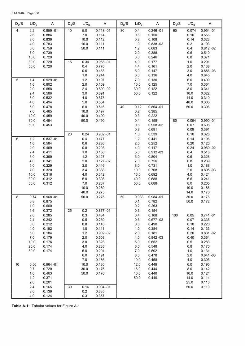
KTA 3204 Page 138
Do/S L/Do A Do/S L/Do A Do/S L/Do A Do/S L/Do A
4 2.2 0.959 -01 10 5.0 0.118 -01 30 0.4 0.246 -01 60 0.074 0.954 -01 2.6 0.884 7.0 0.114 0.6 0.150 0.10 0.556 3.0 0.839 10.0 0.112 0.8 0.108 0.14 0.323 4.0 0.783 16.0 0.111 1.0 0.838 -02 0.2 0.193 5.0 0.759 50.0 0.111 1.2 0.683 0.4 0.812 -02 7.0 0.739 2.0 0.388 0.6 0.510 10.0 0.729 3.0 0.246 0.8 0.371 30.0 0.720 15 0.34 0.968 -01 4.0 0.177 1.0 0.291 50.0 0.720 0.4 0.770 4.4 0.161 2.0 0.138 0.6 0.453 5.0 0.147 3.0 0.886 -03 1.0 0.244 6.0 0.136 4.0 0.645 5 1.4 0.929 -01 1.2 0.197 7.0 0.130 6.0 0.409 1.6 0.802 2.0 0.109 10.0 0.125 7.0 0.364 2.0 0.658 2.4 0.890 -02 30.0 0.122 8.0 0.341 2.4 0.586 3.0 0.691 50.0 0.122 10.0 0.322 3.0 0.532 4.0 0.573 14.0 0.310 4.0 0.494 5.0 0.534 40.0 0.306 5.0 0.478 6.0 0.516 40 0.12 0.864 -01 50.0 0.306 7.0 0.465 10.0 0.497 0.2 0.385 10.0 0.459 40.0 0.490 0.3 0.222 30.0 0.454 50.0 0.490 0.4 0.155 80 0.054 0.990 -01 50.0 0.453 0.6 0.958 -02 0.07 0.608 0.8 0.691 0.09 0.391 20 0.24 0.982 -01 1.0 0.539 0.10 0.328 6 1.2 0.837 -01 0.4 0.477 1.2 0.441 0.14 0.196 1.6 0.584 0.6 0.286 2.0 0.252 0.20 0.120 2.0 0.469 0.8 0.203 4.0 0.117 0.24 0.950 -02 2.4 0.411 1.0 0.156 5.0 0.912 -03 0.4 0.516 3.0 0.369 1.2 0.127 6.0 0.804 0.6 0.328 4.0 0.341 2.0 0.127 -02 7.0 0.756 0.8 0.239 5.0 0.329 3.0 0.446 8.0 0.731 1.0 0.188 7.0 0.320 3.4 0.388 10.0 0.708 2.0 0.895 -03 10.0 0.316 4.0 0.342 16.0 0.692 4.0 0.424 30.0 0.312 5.0 0.308 40.0 0.688 6.6 0.241 50.0 0.312 7.0 0.287 50.0 0.688 8.0 0.205 10.0 0.280 10.0 0.186 40.0 0.275 14.0 0.176 8 0.74 0.968 -01 50.0 0.275 50 0.088 0.984 -01 30.0 0.176 0.8 0.875 0.1 0.782 50.0 0.172 1.0 0.660 0.2 0.263 1.6 0.372 25 0.2 0.877 -01 0.3 0.154 2.0 0.285 0.3 0.484 0.4 0.108 100 0.05 0.741 -01 2.4 0.242 0.5 0.250 0.6 0.677 -02 0.07 0.338 3.0 0.212 0.8 0.143 0.8 0.490 0.10 0.220 4.0 0.192 1.0 0.111 1.0 0.384 0.14 0.133 5.0 0.184 1.2 0.902 -02 2.0 0.181 0.20 0.831 -02 7.0 0.179 2.0 0.508 4.0 0.842 -03 0.40 0.364 10.0 0.176 3.0 0.323 5.0 0.652 0.5 0.283 20.0 0.174 4.0 0.235 6.0 0.548 0.8 0.170 50.0 0.174 5.0 0.204 7.0 0.502 1.0 0.134 6.0 0.191 8.0 0.478 2.0 0.641 -03 7.0 0.186 10.0 0.458 4.0 0.305 10 0.56 0.964 -01 10.0 0.180 12.0 0.449 6.0 0.195 0.7 0.720 30.0 0.176 16.0 0.444 8.0 0.142 1.0 0.463 50.0 0.176 40.0 0.440 10.0 0.124 1.2 0.371 50.0 0.440 14.0 0.114 2.0 0.201 25.0 0.110 2.4 0.165 30 0.16 0.904 -01 50.0 0.110 3.0 0.139 0.2 0.635 4.0 0.124 0.3 0.357
Table A-1: Tabular values for Figure A-1
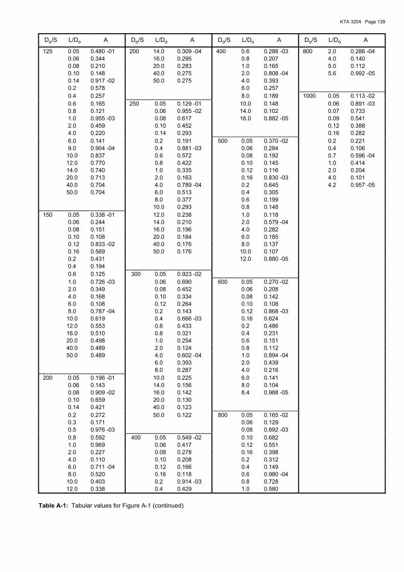
KTA 3204 Page 139
Do/S L/Do A Do/S L/Do A Do/S L/Do A Do/S L/Do A
125 0.05 0.480 -01 200 14.0 0.309 -04 400 0.6 0.288 -03 800 2.0 0.286 -04 0.06 0.344 16.0 0.295 0.8 0.207 4.0 0.140 0.08 0.210 20.0 0.283 1.0 0.165 5.0 0.112 0.10 0.148 40.0 0.275 2.0 0.808 -04 5.6 0.992 -05 0.14 0.917 -02 50.0 0.275 4.0 0.393 0.2 0.578 6.0 0.257 0.4 0.257 8.0 0.189 1000 0.05 0.113 -02 0.6 0.165 250 0.05 0.129 -01 10.0 0.148 0.06 0.891 -03 0.8 0.121 0.06 0.955 -02 14.0 0.102 0.07 0.733 1.0 0.955 -03 0.08 0.617 16.0 0.882 -05 0.09 0.541 2.0 0.459 0.10 0.452 0.12 0.388 4.0 0.220 0.14 0.293 0.16 0.282 6.0 0.141 0.2 0.191 500 0.05 0.370 -02 0.2 0.221 9.0 0.904 -04 0.4 0.881 -03 0.06 0.284 0.4 0.106 10.0 0.837 0.6 0.572 0.08 0.192 0.7 0.596 -04 12.0 0.770 0.8 0.422 0.10 0.145 1.0 0.414 14.0 0.740 1.0 0.335 0.12 0.116 2.0 0.204 20.0 0.713 2.0 0.163 0.16 0.830 -03 4.0 0.101 40.0 0.704 4.0 0.789 -04 0.2 0.645 4.2 0.957 -05 50.0 0.704 6.0 0.513 0.4 0.305 8.0 0.377 0.6 0.199 10.0 0.293 0.8 0.148 150 0.05 0.338 -01 12.0 0.238 1.0 0.118 0.06 0.244 14.0 0.210 2.0 0.579 -04 0.08 0.151 16.0 0.196 4.0 0.282 0.10 0.108 20.0 0.184 6.0 0.185 0.12 0.833 -02 40.0 0.176 8.0 0.137 0.16 0.569 50.0 0.176 10.0 0.107 0.2 0.431 12.0 0.880 -05 0.4 0.194 0.6 0.125 300 0.05 0.923 -02 1.0 0.726 -03 0.06 0.690 600 0.05 0.270 -02 2.0 0.349 0.08 0.452 0.06 0.208 4.0 0.168 0.10 0.334 0.08 0.142 6.0 0.108 0.12 0.264 0.10 0.108 8.0 0.787 -04 0.2 0.143 0.12 0.868 -03 10.0 0.619 0.4 0.666 -03 0.16 0.624 12.0 0.553 0.6 0.433 0.2 0.486 16.0 0.510 0.8 0.321 0.4 0.231 20.0 0.498 1.0 0.254 0.6 0.151 40.0 0.489 2.0 0.124 0.8 0.112 50.0 0.489 4.0 0.602 -04 1.0 0.894 -04 6.0 0.393 2.0 0.439 8.0 0.287 4.0 0.216 200 0.05 0.196 -01 10.0 0.225 6.0 0.141 0.06 0.143 14.0 0.156 8.0 0.104 0.08 0.909 -02 16.0 0.142 8.4 0.988 -05 0.10 0.659 20.0 0.130 0.14 0.421 40.0 0.123 0.2 0.272 50.0 0.122 800 0.05 0.165 -02 0.3 0.171 0.06 0.129 0.5 0.976 -03 0.08 0.892 -03 0.8 0.592 400 0.05 0.549 -02 0.10 0.682 1.0 0.969 0.06 0.417 0.12 0.551 2.0 0.227 0.08 0.278 0.16 0.398 4.0 0.110 0.10 0.208 0.2 0.312 6.0 0.711 -04 0.12 0.166 0.4 0.149 8.0 0.520 0.16 0.118 0.6 0.980 -04 10.0 0.403 0.2 0.914 -03 0.8 0.728 12.0 0.338 0.4 0.429 1.0 0.580
Table A-1: Tabular values for Figure A-1 (continued)
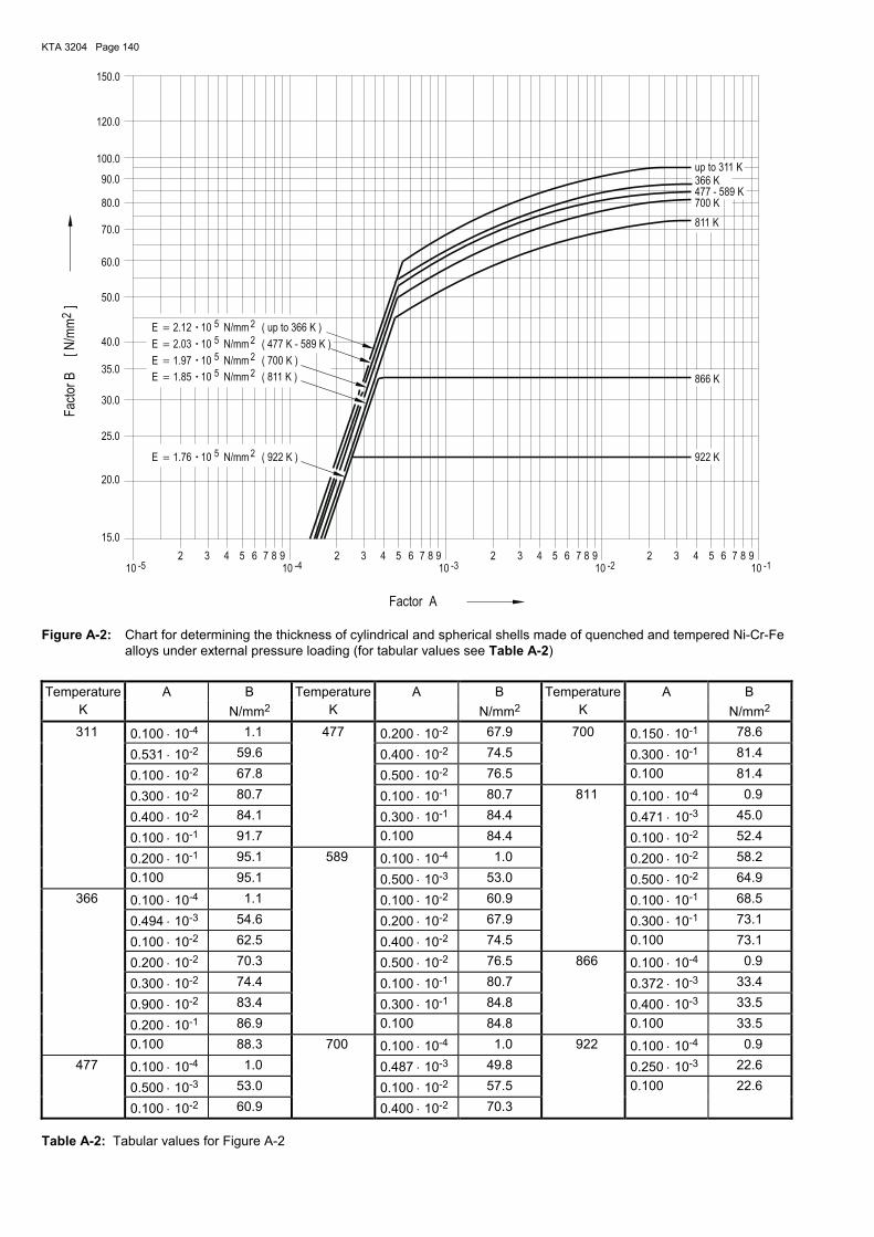
KTA 3204 Page 140
=
=
==
=
-4
2
2
5
-1
5
-2
2
5 2
25
-5
5
-3
E 1.97
2.12E 10 N/mm
N/mm10E 2.03
N/mm
up to 311 K366 K
( 922 K )
( 700 K )
( 811 K ) 866 K
922 K
811 K
477 - 589 K700 K
( 477 K - 589 K )
N/mm101.85
10
E
10
( up to 366 K )
N/mmE 1.76
150.0
210 10
543 5 6 72 3 464 5 610
2 3 9877 8 9
80.0
70.0
50.0
25.0
60.0
90.0
120.0
100.0
15.0
40.0
30.0
20.0
35.0
876 8 9910 10
2 543
2
Factor A
Fac
tor
B[ N
/mm
]
Figure A-2: Chart for determining the thickness of cylindrical and spherical shells made of quenched and tempered Ni-Cr-Fe alloys under external pressure loading (for tabular values see Table A-2)
Temperature A B Temperature A B Temperature A B K N/mm2 K N/mm2 K N/mm2
311 0.100 ⋅ 10-4 1.1 477 0.200 ⋅ 10-2 67.9 700 0.150 ⋅ 10-1 78.6 0.531 ⋅ 10-2 59.6 0.400 ⋅ 10-2 74.5 0.300 ⋅ 10-1 81.4 0.100 ⋅ 10-2 67.8 0.500 ⋅ 10-2 76.5 0.100 81.4 0.300 ⋅ 10-2 80.7 0.100 ⋅ 10-1 80.7 811 0.100 ⋅ 10-4 0.9 0.400 ⋅ 10-2 84.1 0.300 ⋅ 10-1 84.4 0.471 ⋅ 10-3 45.0 0.100 ⋅ 10-1 91.7 0.100 84.4 0.100 ⋅ 10-2 52.4 0.200 ⋅ 10-1 95.1 589 0.100 ⋅ 10-4 1.0 0.200 ⋅ 10-2 58.2 0.100 95.1 0.500 ⋅ 10-3 53.0 0.500 ⋅ 10-2 64.9
366 0.100 ⋅ 10-4 1.1 0.100 ⋅ 10-2 60.9 0.100 ⋅ 10-1 68.5 0.494 ⋅ 10-3 54.6 0.200 ⋅ 10-2 67.9 0.300 ⋅ 10-1 73.1 0.100 ⋅ 10-2 62.5 0.400 ⋅ 10-2 74.5 0.100 73.1 0.200 ⋅ 10-2 70.3 0.500 ⋅ 10-2 76.5 866 0.100 ⋅ 10-4 0.9 0.300 ⋅ 10-2 74.4 0.100 ⋅ 10-1 80.7 0.372 ⋅ 10-3 33.4 0.900 ⋅ 10-2 83.4 0.300 ⋅ 10-1 84.8 0.400 ⋅ 10-3 33.5 0.200 ⋅ 10-1 86.9 0.100 84.8 0.100 33.5 0.100 88.3 700 0.100 ⋅ 10-4 1.0 922 0.100 ⋅ 10-4 0.9
477 0.100 ⋅ 10-4 1.0 0.487 ⋅ 10-3 49.8 0.250 ⋅ 10-3 22.6 0.500 ⋅ 10-3 53.0 0.100 ⋅ 10-2 57.5 0.100 22.6 0.100 ⋅ 10-2 60.9 0.400 ⋅ 10-2 70.3
Table A-2: Tabular values for Figure A-2
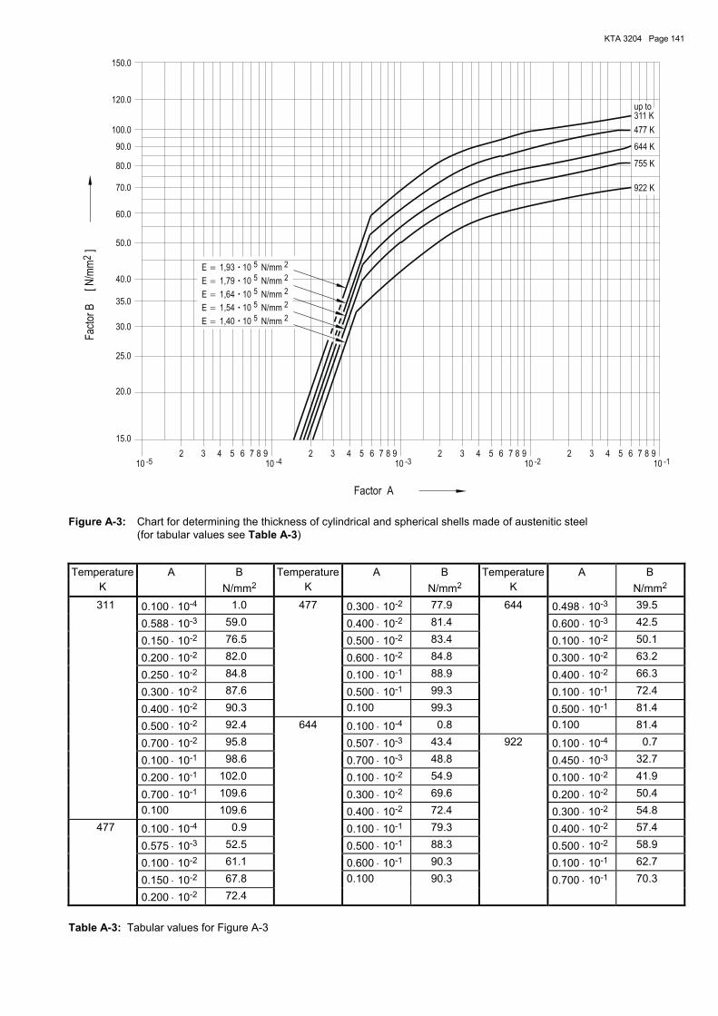
KTA 3204 Page 141
=
=
==
=
-4
2
-2 -1
25
2
-3
5
5
25
2
-5
5
150.0
N/mm10
100.0
15.0
1,93
E
E
1,79
10 N/mm
10
922 K
1,40 N/mm
311 K
477 K
up to
755 K
644 K
N/mm10E 1,64
E 10
E
1,54 N/mm
120.0
32 4 6510
4 5310
274 5310
2 6 9897 8 6
60.0
90.0
25.0
10
35.0
80.0
30.0
20.0
40.0
70.0
50.0
1098 97 873 42 65
2
Factor A
Fac
tor
B[ N
/mm
]
Figure A-3: Chart for determining the thickness of cylindrical and spherical shells made of austenitic steel (for tabular values see Table A-3)
Temperature A B Temperature A B Temperature A B K N/mm2 K N/mm2 K N/mm2
311 0.100 ⋅ 10-4 1.0 477 0.300 ⋅ 10-2 77.9 644 0.498 ⋅ 10-3 39.5 0.588 ⋅ 10-3 59.0 0.400 ⋅ 10-2 81.4 0.600 ⋅ 10-3 42.5 0.150 ⋅ 10-2 76.5 0.500 ⋅ 10-2 83.4 0.100 ⋅ 10-2 50.1 0.200 ⋅ 10-2 82.0 0.600 ⋅ 10-2 84.8 0.300 ⋅ 10-2 63.2 0.250 ⋅ 10-2 84.8 0.100 ⋅ 10-1 88.9 0.400 ⋅ 10-2 66.3 0.300 ⋅ 10-2 87.6 0.500 ⋅ 10-1 99.3 0.100 ⋅ 10-1 72.4 0.400 ⋅ 10-2 90.3 0.100 99.3 0.500 ⋅ 10-1 81.4 0.500 ⋅ 10-2 92.4 644 0.100 ⋅ 10-4 0.8 0.100 81.4 0.700 ⋅ 10-2 95.8 0.507 ⋅ 10-3 43.4 922 0.100 ⋅ 10-4 0.7 0.100 ⋅ 10-1 98.6 0.700 ⋅ 10-3 48.8 0.450 ⋅ 10-3 32.7 0.200 ⋅ 10-1 102.0 0.100 ⋅ 10-2 54.9 0.100 ⋅ 10-2 41.9 0.700 ⋅ 10-1 109.6 0.300 ⋅ 10-2 69.6 0.200 ⋅ 10-2 50.4 0.100 109.6 0.400 ⋅ 10-2 72.4 0.300 ⋅ 10-2 54.8
477 0.100 ⋅ 10-4 0.9 0.100 ⋅ 10-1 79.3 0.400 ⋅ 10-2 57.4 0.575 ⋅ 10-3 52.5 0.500 ⋅ 10-1 88.3 0.500 ⋅ 10-2 58.9 0.100 ⋅ 10-2 61.1 0.600 ⋅ 10-1 90.3 0.100 ⋅ 10-1 62.7 0.150 ⋅ 10-2 67.8 0.100 90.3 0.700 ⋅ 10-1 70.3 0.200 ⋅ 10-2 72.4
Table A-3: Tabular values for Figure A-3
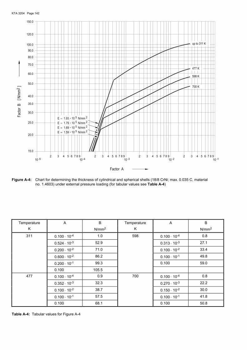
KTA 3204 Page 142
==== 2
-3 -2
5
-1
5
25
25
2
-4-5
N/mm
98
1.79
E
8
10
9
E
10
6
150.0
5 7
E N/mm1.93
1.69
up to 311 K
598 K
10
3210
477 K
700 K
4
10
6
N/mm
7
1.59 N/mmE
5 98 8 9743 652 210 10
3 6 74 5
50.0
40.0
80.0
70.0
30,0
100.0
15.0
20.0
120.0
24310 10
60.0
90.0
25.0
35.0
2
Factor A
Fac
tor
B[ N
/mm
]
Figure A-4: Chart for determining the thickness of cylindrical and spherical shells (18/8 CrNi; max. 0.035 C, material no. 1.4603) under external pressure loading (for tabular values see Table A-4)
Temperature A B Temperature A B
K N/mm2 K N/mm2
311 0.100 ⋅ 10-4 1.0 598 0.100 ⋅ 10-4 0.8
0.524 ⋅ 10-3 52.9 0.313 ⋅ 10-3 27.1
0.200 ⋅ 10-2 71.0 0.100 ⋅ 10-2 33.4
0.600 ⋅ 10-2 86.2 0.100 ⋅ 10-1 49.8
0.200 ⋅ 10-1 99.3 0.100 59.0
0.100 105.5
477 0.100 ⋅ 10-4 0.9 700 0.100 ⋅ 10-4 0.8
0.352 ⋅ 10-3 32.3 0.270 ⋅ 10-3 22.2
0.100 ⋅ 10-2 38.7 0.150 ⋅ 10-2 30.0
0.100 ⋅ 10-1 57.5 0.100 ⋅ 10-1 41.8
0.100 68.1 0.100 50.8
Table A-4: Tabular values for Figure A-4
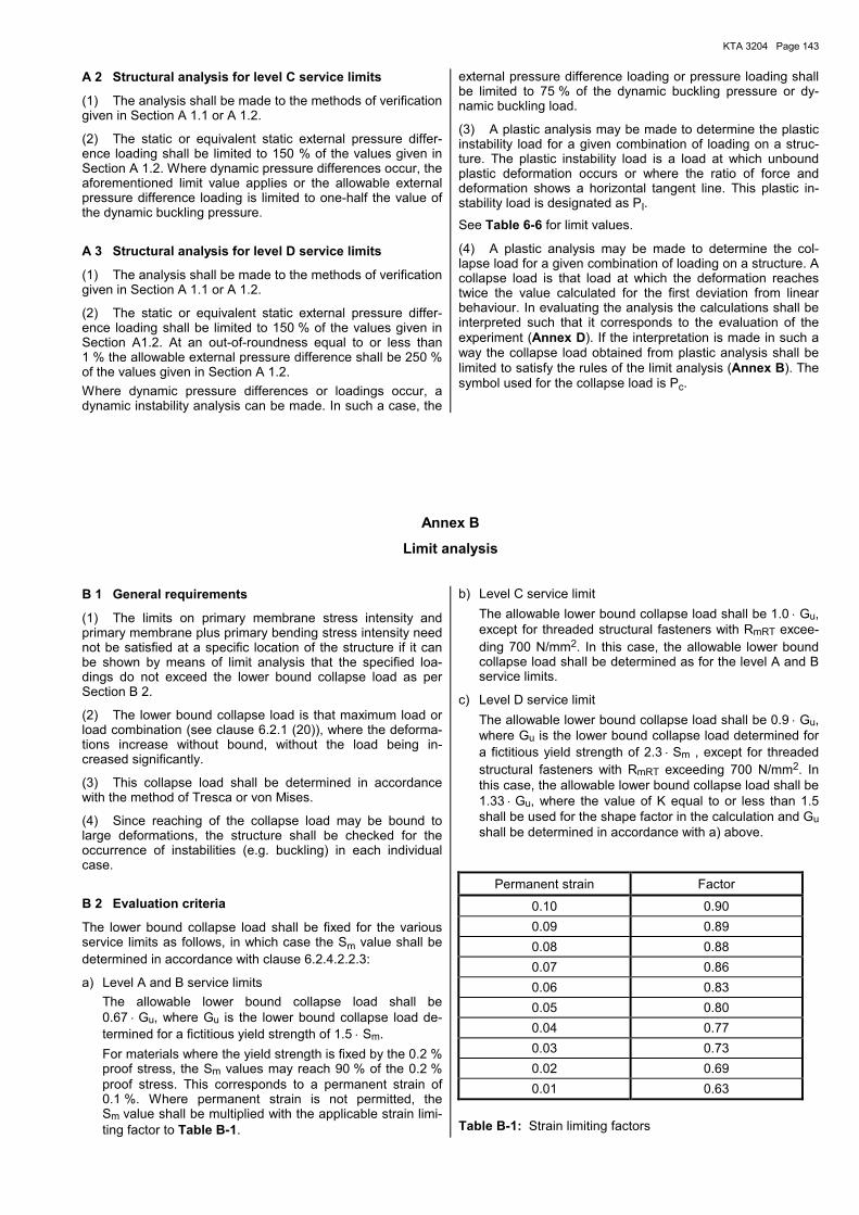
KTA 3204 Page 143
A 2 Structural analysis for level C service limits
(1) The analysis shall be made to the methods of verification given in Section A 1.1 or A 1.2.
(2) The static or equivalent static external pressure differ-ence loading shall be limited to 150 % of the values given in Section A 1.2. Where dynamic pressure differences occur, the aforementioned limit value applies or the allowable external pressure difference loading is limited to one-half the value of the dynamic buckling pressure.
A 3 Structural analysis for level D service limits
(1) The analysis shall be made to the methods of verification given in Section A 1.1 or A 1.2.
(2) The static or equivalent static external pressure differ-ence loading shall be limited to 150 % of the values given in Section A1.2. At an out-of-roundness equal to or less than 1 % the allowable external pressure difference shall be 250 % of the values given in Section A 1.2. Where dynamic pressure differences or loadings occur, a dynamic instability analysis can be made. In such a case, the
external pressure difference loading or pressure loading shall be limited to 75 % of the dynamic buckling pressure or dy-namic buckling load.
(3) A plastic analysis may be made to determine the plastic instability load for a given combination of loading on a struc-ture. The plastic instability load is a load at which unbound plastic deformation occurs or where the ratio of force and deformation shows a horizontal tangent line. This plastic in-stability load is designated as PI.
See Table 6-6 for limit values.
(4) A plastic analysis may be made to determine the col-lapse load for a given combination of loading on a structure. A collapse load is that load at which the deformation reaches twice the value calculated for the first deviation from linear behaviour. In evaluating the analysis the calculations shall be interpreted such that it corresponds to the evaluation of the experiment (Annex D). If the interpretation is made in such a way the collapse load obtained from plastic analysis shall be limited to satisfy the rules of the limit analysis (Annex B). The symbol used for the collapse load is Pc.
Annex B
Limit analysis B 1 General requirements
(1) The limits on primary membrane stress intensity and primary membrane plus primary bending stress intensity need not be satisfied at a specific location of the structure if it can be shown by means of limit analysis that the specified loa-dings do not exceed the lower bound collapse load as per Section B 2.
(2) The lower bound collapse load is that maximum load or load combination (see clause 6.2.1 (20)), where the deforma-tions increase without bound, without the load being in-creased significantly.
(3) This collapse load shall be determined in accordance with the method of Tresca or von Mises.
(4) Since reaching of the collapse load may be bound to large deformations, the structure shall be checked for the occurrence of instabilities (e.g. buckling) in each individual case.
B 2 Evaluation criteria
The lower bound collapse load shall be fixed for the various service limits as follows, in which case the Sm value shall be determined in accordance with clause 6.2.4.2.2.3:
a) Level A and B service limits The allowable lower bound collapse load shall be
0.67 ⋅ Gu, where Gu is the lower bound collapse load de-termined for a fictitious yield strength of 1.5 ⋅ Sm.
For materials where the yield strength is fixed by the 0.2 % proof stress, the Sm values may reach 90 % of the 0.2 % proof stress. This corresponds to a permanent strain of 0.1 %. Where permanent strain is not permitted, the Sm value shall be multiplied with the applicable strain limi-ting factor to Table B-1.
b) Level C service limit The allowable lower bound collapse load shall be 1.0 ⋅ Gu,
except for threaded structural fasteners with RmRT excee-ding 700 N/mm2. In this case, the allowable lower bound collapse load shall be determined as for the level A and B service limits.
c) Level D service limit The allowable lower bound collapse load shall be 0.9 ⋅ Gu,
where Gu is the lower bound collapse load determined for a fictitious yield strength of 2.3 ⋅ Sm , except for threaded structural fasteners with RmRT exceeding 700 N/mm2. In this case, the allowable lower bound collapse load shall be 1.33 ⋅ Gu, where the value of K equal to or less than 1.5 shall be used for the shape factor in the calculation and Gu shall be determined in accordance with a) above.
Permanent strain Factor
0.10 0.90 0.09 0.89 0.08 0.88 0.07 0.86 0.06 0.83 0.05 0.80 0.04 0.77 0.03 0.73 0.02 0.69 0.01 0.63
Table B-1: Strain limiting factors
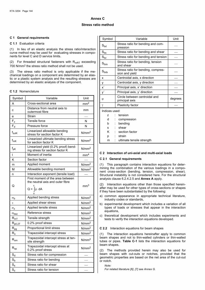
KTA 3204 Page 144
Annex C
Stress ratio method C 1 General requirements
C 1.1 Evaluation criteria
(1) In lieu of an elastic analysis the stress ratio/interaction curve method may be used for evaluating stresses in compo-nents for level C and D service limits.
(2) For threaded structural fasteners with RmRT exceeding 700 N/mm2 the stress ratio method shall not be used.
(3) The stress ratio method is only applicable if the me-chanical loadings on a component are determined by an elas-tic or a plastic system analysis and the resulting stresses are determined by an elastic analysis of the component.
C 1.2 Nomenclature
Symbol Variable Unit
A Cross-sectional area mm2
c Distance from neutral axis to outermost fibre mm
e Strain Fz Tensile force N Fd Pressure force N
fzulK Linearized allowable bending stress for section factor K N/mm2
fmK Linearized ultimate bending stress for section factor K N/mm2
fpK Linearized yield (0.2% proof) bend-ing stress for section factor K N/mm2
I Moment of inertia mm4 K Section factor m Applied moment N/mm2 M Allowable bending moment N/mm2 n Interaction exponent (tensile load)
Q
First moment of the area between the neutral axis and outer fibre
Q = ∫ ⋅c
o
dAy mm3
σb Applied bending stress N/mm2 τ Applied shear stress N/mm2 σz Applied tensile stress N/mm2 σbez Reference stress N/mm2 RmT Tensile strength N/mm2 Rp0.2T 0.2% proof stress N/mm2 Rpg Proportional limit stress N/mm2 Ro Trapezoidal intercept stress N/mm2
Rom Trapezoidal intercept stress at ten-sile strength N/mm2
Rop Trapezoidal intercept stress at 0.2% proof stress N/mm2
Sd Stress ratio for compression Sb Stress ratio for bending Ss Stress ratio for shear Sz Stress ratio for tension
Symbol Variable Unit
Sbd Stress ratio for bending and com-pression
Sbs Stress ratio for bending and shear Sbz Stress ratio for bending and tension
Sbzs Stress ratio for bending, tension and shear
Sbds Stress ratio for bending, compres-sion and yield
x Centroidal axis, x direction y Centroidal axis, y direction x´ Principal axis, x� direction y´ Principal axis, y� direction
ϕ Circle between centroidal and principal axis degrees
γ Plasticity factor
Indices used: z : tension d : compression b : bending s : shear K : section factor p : strain m : ultimate tensile strength
C 2 Interaction of uni-axial and multi-axial loads
C 2.1 General requirements
(1) This paragraph contains interaction equations for deter-mining the combination of the various loadings in a compo-nent cross-section (bending, tension, compression, shear). Structural instability is not considered here. For the structural analysis clause 6.2.4.2.5 and Annex A apply.
(2) Interaction equations other than those specified herein-after may be used for other types of cross-sections or shapes if they have been substantiated by the following: a) common appearance in appropriate technical literature,
industry codes or standards, b) experimental development which includes a variation of all
types of loads or stresses that appear in the interaction equations,
c) theoretical development which includes experiments and tests to verify the interaction equations developed.
C 2.2 Interaction equations for beam shapes
(1) The interaction equations hereinafter apply to common beam shapes and not to thin-walled cylinders or thin-walled tubes or pipes. Table C-1 lists the interaction equations for beam shapes.
(2) The methods provided herein may also be used for beam shapes with cut-outs or notches, provided that the geometric properties are based on the net area of the cut-out or notch.
Note: For related literature [6], [7] see Annex G.
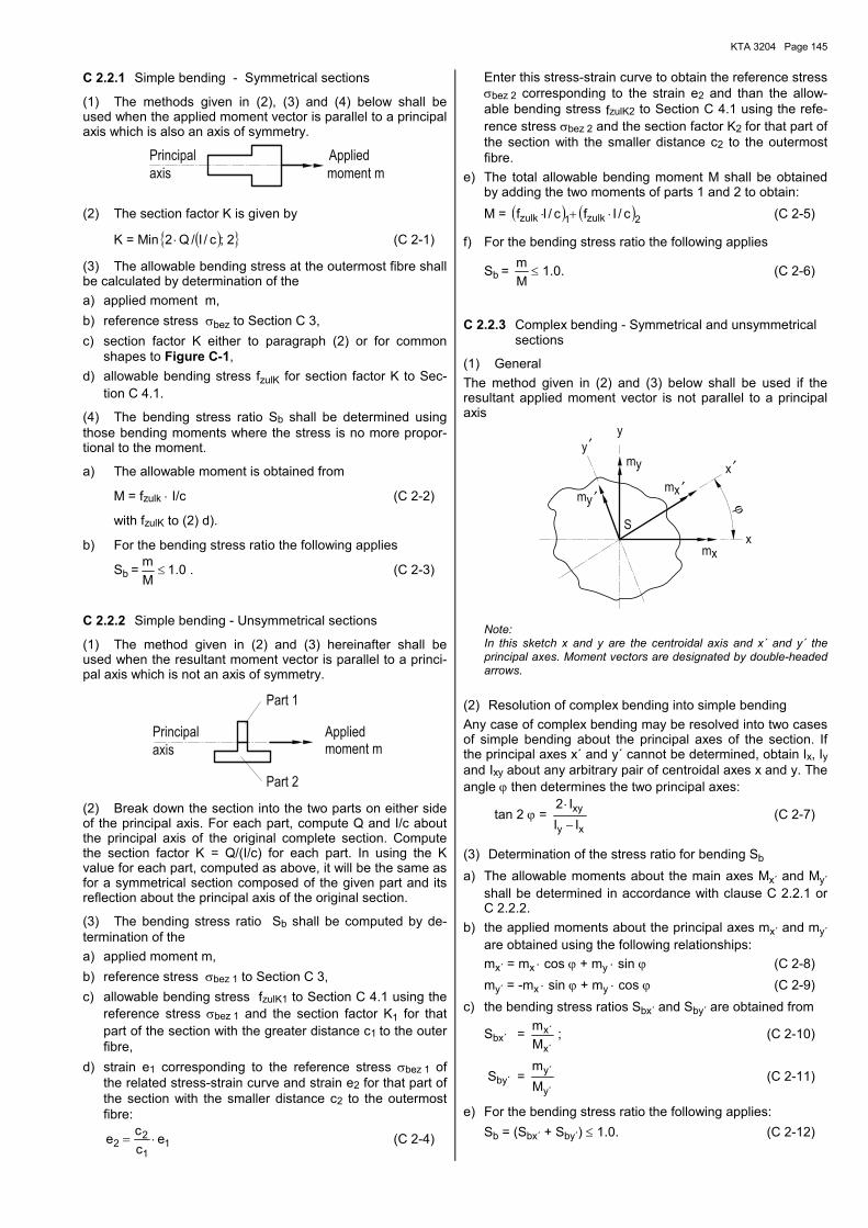
KTA 3204 Page 145
C 2.2.1 Simple bending - Symmetrical sections
(1) The methods given in (2), (3) and (4) below shall be used when the applied moment vector is parallel to a principal axis which is also an axis of symmetry.
moment m
Applied
axis
Principal
(2) The section factor K is given by
K = Min ( ){ }2;c/I/Q2 ⋅ (C 2-1)
(3) The allowable bending stress at the outermost fibre shall be calculated by determination of the a) applied moment m, b) reference stress σbez to Section C 3, c) section factor K either to paragraph (2) or for common
shapes to Figure C-1, d) allowable bending stress fzulK for section factor K to Sec-
tion C 4.1.
(4) The bending stress ratio Sb shall be determined using those bending moments where the stress is no more propor-tional to the moment.
a) The allowable moment is obtained from
M = fzulk ⋅ I/c (C 2-2)
with fzulK to (2) d).
b) For the bending stress ratio the following applies
Sb = 0.1Mm
≤ . (C 2-3)
C 2.2.2 Simple bending - Unsymmetrical sections
(1) The method given in (2) and (3) hereinafter shall be used when the resultant moment vector is parallel to a princi-pal axis which is not an axis of symmetry.
Part 2
moment mAppliedPrincipal
Part 1
axis
(2) Break down the section into the two parts on either side of the principal axis. For each part, compute Q and I/c about the principal axis of the original complete section. Compute the section factor K = Q/(I/c) for each part. In using the K value for each part, computed as above, it will be the same as for a symmetrical section composed of the given part and its reflection about the principal axis of the original section.
(3) The bending stress ratio Sb shall be computed by de-termination of the a) applied moment m, b) reference stress σbez 1 to Section C 3, c) allowable bending stress fzulK1 to Section C 4.1 using the
reference stress σbez 1 and the section factor K1 for that part of the section with the greater distance c1 to the outer fibre,
d) strain e1 corresponding to the reference stress σbez 1 of the related stress-strain curve and strain e2 for that part of the section with the smaller distance c2 to the outermost fibre:
11
22 e
cce ⋅= (C 2-4)
Enter this stress-strain curve to obtain the reference stress σbez 2 corresponding to the strain e2 and than the allow-able bending stress fzulK2 to Section C 4.1 using the refe-rence stress σbez 2 and the section factor K2 for that part of the section with the smaller distance c2 to the outermost fibre.
e) The total allowable bending moment M shall be obtained by adding the two moments of parts 1 and 2 to obtain:
M = ( ) ( )2zulk1zulk c/Ifc/If ⋅+⋅ (C 2-5)
f) For the bending stress ratio the following applies
Sb = Mm
≤ 1.0. (C 2-6)
C 2.2.3 Complex bending - Symmetrical and unsymmetrical sections
(1) General The method given in (2) and (3) below shall be used if the resultant applied moment vector is not parallel to a principal axis
′′
′ ϕ
′
m
my
x
y
x
Sx
mm
y
yx
Note: In this sketch x and y are the centroidal axis and x´ and y´ the principal axes. Moment vectors are designated by double-headed arrows.
(2) Resolution of complex bending into simple bending Any case of complex bending may be resolved into two cases of simple bending about the principal axes of the section. If the principal axes x´ and y´ cannot be determined, obtain Ix, Iy and Ixy about any arbitrary pair of centroidal axes x and y. The angle ϕ then determines the two principal axes:
tan 2 ϕ = xy
xy
III2−
⋅ (C 2-7)
(3) Determination of the stress ratio for bending Sb a) The allowable moments about the main axes Mx´ and My´
shall be determined in accordance with clause C 2.2.1 or C 2.2.2.
b) the applied moments about the principal axes mx´ and my´ are obtained using the following relationships:
mx´ = mx ⋅ cos ϕ + my ⋅ sin ϕ (C 2-8) my´ = -mx ⋅ sin ϕ + my ⋅ cos ϕ (C 2-9) c) the bending stress ratios Sbx´ and Sby´ are obtained from
Sbx´ = ´x
´xMm ; (C 2-10)
Sby´ = ´y
´y
Mm
(C 2-11)
e) For the bending stress ratio the following applies: Sb = (Sbx´ + Sby´) ≤ 1.0. (C 2-12)
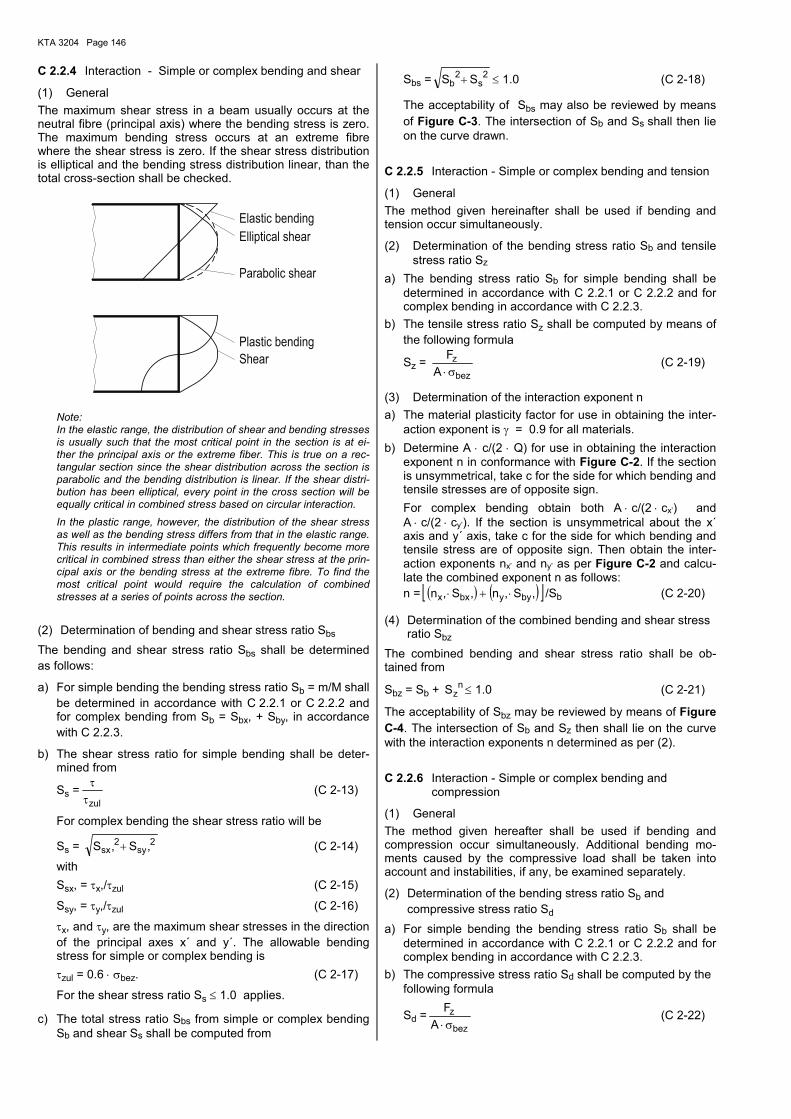
KTA 3204 Page 146
C 2.2.4 Interaction - Simple or complex bending and shear
(1) General The maximum shear stress in a beam usually occurs at the neutral fibre (principal axis) where the bending stress is zero. The maximum bending stress occurs at an extreme fibre where the shear stress is zero. If the shear stress distribution is elliptical and the bending stress distribution linear, than the total cross-section shall be checked.
Shear
Elliptical shear
Elastic bending
Plastic bending
Parabolic shear
Note: In the elastic range, the distribution of shear and bending stresses is usually such that the most critical point in the section is at ei-ther the principal axis or the extreme fiber. This is true on a rec-tangular section since the shear distribution across the section is parabolic and the bending distribution is linear. If the shear distri-bution has been elliptical, every point in the cross section will be equally critical in combined stress based on circular interaction. In the plastic range, however, the distribution of the shear stress as well as the bending stress differs from that in the elastic range. This results in intermediate points which frequently become more critical in combined stress than either the shear stress at the prin-cipal axis or the bending stress at the extreme fibre. To find the most critical point would require the calculation of combined stresses at a series of points across the section.
(2) Determination of bending and shear stress ratio Sbs The bending and shear stress ratio Sbs shall be determined as follows:
a) For simple bending the bending stress ratio Sb = m/M shall be determined in accordance with C 2.2.1 or C 2.2.2 and for complex bending from Sb = Sbx, + Sby, in accordance with C 2.2.3.
b) The shear stress ratio for simple bending shall be deter-mined from
Ss =zulττ (C 2-13)
For complex bending the shear stress ratio will be
Ss = 2sy
2sx ,S,S + (C 2-14)
with Ssx, = τx,/τzul (C 2-15)
Ssy, = τy,/τzul (C 2-16)
τx, and τy, are the maximum shear stresses in the direction of the principal axes x´ and y´. The allowable bending stress for simple or complex bending is
τzul = 0.6 ⋅ σbez. (C 2-17)
For the shear stress ratio Ss ≤ 1.0 applies.
c) The total stress ratio Sbs from simple or complex bending Sb and shear Ss shall be computed from
Sbs =2
s2
b SS + ≤ 1.0 (C 2-18)
The acceptability of Sbs may also be reviewed by means of Figure C-3. The intersection of Sb and Ss shall then lie on the curve drawn.
C 2.2.5 Interaction - Simple or complex bending and tension
(1) General The method given hereinafter shall be used if bending and tension occur simultaneously.
(2) Determination of the bending stress ratio Sb and tensile stress ratio Sz
a) The bending stress ratio Sb for simple bending shall be determined in accordance with C 2.2.1 or C 2.2.2 and for complex bending in accordance with C 2.2.3.
b) The tensile stress ratio Sz shall be computed by means of the following formula
Sz = bez
zA
Fσ⋅
(C 2-19)
(3) Determination of the interaction exponent n a) The material plasticity factor for use in obtaining the inter-
action exponent is γ = 0.9 for all materials. b) Determine A ⋅ c/(2 ⋅ Q) for use in obtaining the interaction
exponent n in conformance with Figure C-2. If the section is unsymmetrical, take c for the side for which bending and tensile stresses are of opposite sign.
For complex bending obtain both A ⋅ c/(2 ⋅ cx�) and A ⋅ c/(2 ⋅ cy�). If the section is unsymmetrical about the x´ axis and y´ axis, take c for the side for which bending and tensile stress are of opposite sign. Then obtain the inter-action exponents nx� and ny� as per Figure C-2 and calcu-late the combined exponent n as follows:
n = ( ) ( )[ ],S,n,S,n byybxx ⋅+⋅ /Sb (C 2-20)
(4) Determination of the combined bending and shear stress ratio Sbz
The combined bending and shear stress ratio shall be ob-tained from
Sbz = Sb + nzS ≤ 1.0 (C 2-21)
The acceptability of Sbz may be reviewed by means of Figure C-4. The intersection of Sb and Sz then shall lie on the curve with the interaction exponents n determined as per (2).
C 2.2.6 Interaction - Simple or complex bending and compression
(1) General The method given hereafter shall be used if bending and compression occur simultaneously. Additional bending mo-ments caused by the compressive load shall be taken into account and instabilities, if any, be examined separately.
(2) Determination of the bending stress ratio Sb and compressive stress ratio Sd
a) For simple bending the bending stress ratio Sb shall be determined in accordance with C 2.2.1 or C 2.2.2 and for complex bending in accordance with C 2.2.3.
b) The compressive stress ratio Sd shall be computed by the following formula
Sd =bez
zA
Fσ⋅
(C 2-22)
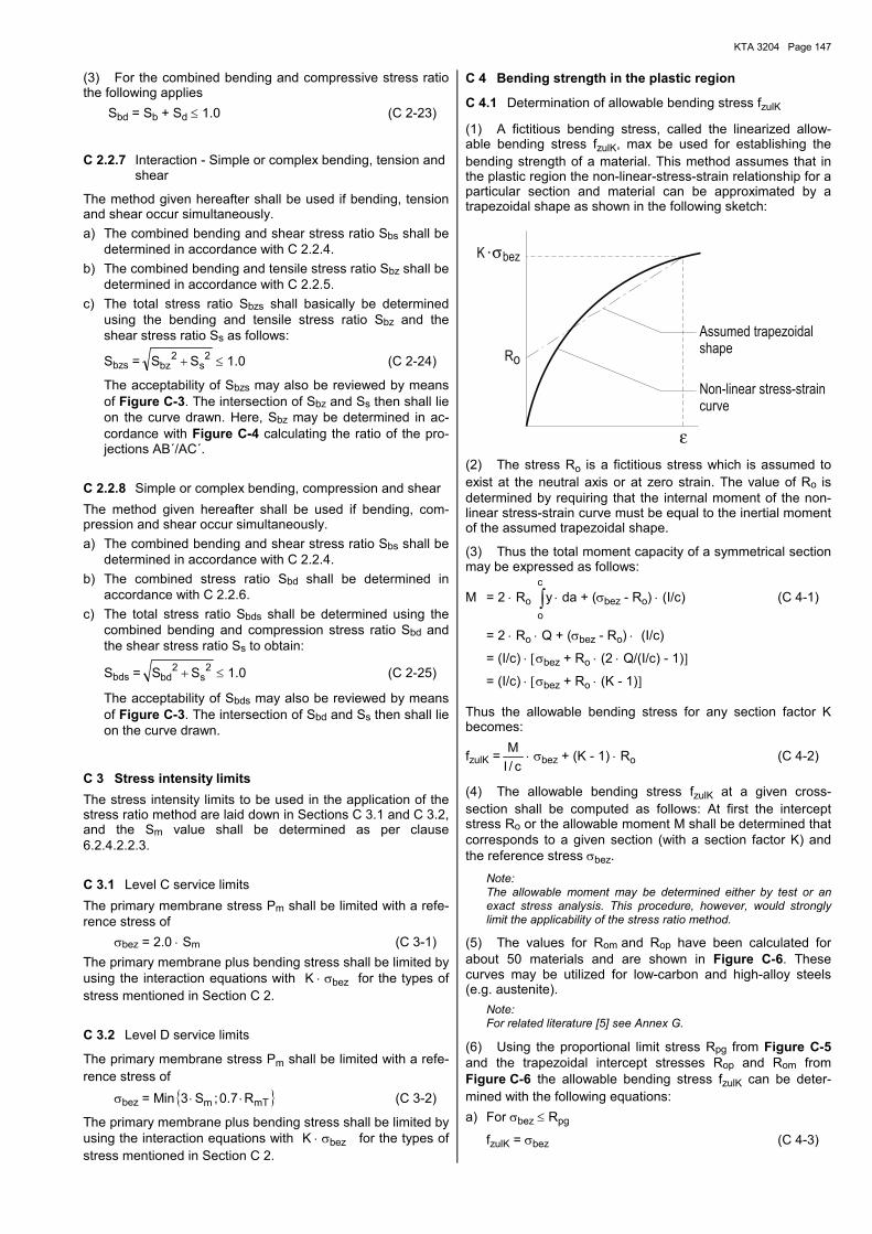
KTA 3204 Page 147
(3) For the combined bending and compressive stress ratio the following applies Sbd = Sb + Sd ≤ 1.0 (C 2-23)
C 2.2.7 Interaction - Simple or complex bending, tension and shear
The method given hereafter shall be used if bending, tension and shear occur simultaneously. a) The combined bending and shear stress ratio Sbs shall be
determined in accordance with C 2.2.4. b) The combined bending and tensile stress ratio Sbz shall be
determined in accordance with C 2.2.5. c) The total stress ratio Sbzs shall basically be determined
using the bending and tensile stress ratio Sbz and the shear stress ratio Ss as follows:
Sbzs =2
s2
bz SS + ≤ 1.0 (C 2-24)
The acceptability of Sbzs may also be reviewed by means of Figure C-3. The intersection of Sbz and Ss then shall lie on the curve drawn. Here, Sbz may be determined in ac-cordance with Figure C-4 calculating the ratio of the pro-jections AB´/AC´.
C 2.2.8 Simple or complex bending, compression and shear The method given hereafter shall be used if bending, com-pression and shear occur simultaneously. a) The combined bending and shear stress ratio Sbs shall be
determined in accordance with C 2.2.4. b) The combined stress ratio Sbd shall be determined in
accordance with C 2.2.6. c) The total stress ratio Sbds shall be determined using the
combined bending and compression stress ratio Sbd and the shear stress ratio Ss to obtain:
Sbds =2
s2
bd SS + ≤ 1.0 (C 2-25)
The acceptability of Sbds may also be reviewed by means of Figure C-3. The intersection of Sbd and Ss then shall lie on the curve drawn.
C 3 Stress intensity limits The stress intensity limits to be used in the application of the stress ratio method are laid down in Sections C 3.1 and C 3.2, and the Sm value shall be determined as per clause 6.2.4.2.2.3.
C 3.1 Level C service limits The primary membrane stress Pm shall be limited with a refe-rence stress of σbez = 2.0 ⋅ Sm (C 3-1) The primary membrane plus bending stress shall be limited by using the interaction equations with K ⋅ σbez for the types of stress mentioned in Section C 2.
C 3.2 Level D service limits
The primary membrane stress Pm shall be limited with a refe-rence stress of σbez = Min { }mTm R7.0;S3 ⋅⋅ (C 3-2)
The primary membrane plus bending stress shall be limited by using the interaction equations with K ⋅ σbez for the types of stress mentioned in Section C 2.
C 4 Bending strength in the plastic region
C 4.1 Determination of allowable bending stress fzulK
(1) A fictitious bending stress, called the linearized allow-able bending stress fzulK, max be used for establishing the bending strength of a material. This method assumes that in the plastic region the non-linear-stress-strain relationship for a particular section and material can be approximated by a trapezoidal shape as shown in the following sketch:
σ
ε
bez
oR
Assumed trapezoidalshape
K
Non-linear stress-straincurve
(2) The stress Ro is a fictitious stress which is assumed to exist at the neutral axis or at zero strain. The value of Ro is determined by requiring that the internal moment of the non-linear stress-strain curve must be equal to the inertial moment of the assumed trapezoidal shape.
(3) Thus the total moment capacity of a symmetrical section may be expressed as follows:
M = 2 ⋅ Ro ∫c
o
y ⋅ da + (σbez - Ro) ⋅ (I/c) (C 4-1)
= 2 ⋅ Ro ⋅ Q + (σbez - Ro) ⋅ (I/c)
= (I/c) ⋅ [σbez + Ro ⋅ (2 ⋅ Q/(I/c) - 1)]
= (I/c) ⋅ [σbez + Ro ⋅ (K - 1)]
Thus the allowable bending stress for any section factor K becomes:
fzulK =c/I
M⋅ σbez + (K - 1) ⋅ Ro (C 4-2)
(4) The allowable bending stress fzulK at a given cross-section shall be computed as follows: At first the intercept stress Ro or the allowable moment M shall be determined that corresponds to a given section (with a section factor K) and the reference stress σbez.
Note: The allowable moment may be determined either by test or an exact stress analysis. This procedure, however, would strongly limit the applicability of the stress ratio method.
(5) The values for Rom and Rop have been calculated for about 50 materials and are shown in Figure C-6. These curves may be utilized for low-carbon and high-alloy steels (e.g. austenite).
Note: For related literature [5] see Annex G.
(6) Using the proportional limit stress Rpg from Figure C-5 and the trapezoidal intercept stresses Rop and Rom from Figure C-6 the allowable bending stress fzulK can be deter-mined with the following equations: a) For σbez ≤ Rpg
fzulK = σbez (C 4-3)
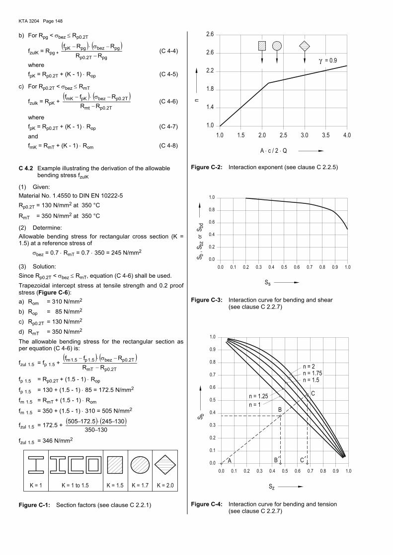
KTA 3204 Page 148
b) For Rpg < σbez ≤ Rp0.2T
fzulK = Rpg + ( ) ( )
pgT2.0p
pgbezpgpK
RRRRf
−
−σ⋅− (C 4-4)
where fpK = Rp0.2T + (K - 1) ⋅ Rop (C 4-5)
c) For Rp0.2T < σbez ≤ RmT
fzulk = RpK + ( ) ( )
T2.0pmt
T2.0pbezpKmK
RRRff
−
−σ⋅− (C 4-6)
where fpK = Rp0.2T + (K - 1) ⋅ Rop (C 4-7) and fmK = RmT + (K - 1) ⋅ Rom (C 4-8)
C 4.2 Example illustrating the derivation of the allowable bending stress fzulK
(1) Given: Material No. 1.4550 to DIN EN 10222-5 Rp0.2T = 130 N/mm2 at 350 °C
RmT = 350 N/mm2 at 350 °C
(2) Determine: Allowable bending stress for rectangular cross section (K = 1.5) at a reference stress of σbez = 0.7 ⋅ RmT = 0.7 ⋅ 350 = 245 N/mm2
(3) Solution: Since Rp0.2T < σbez ≤ RmT, equation (C 4-6) shall be used. Trapezoidal intercept stress at tensile strength and 0.2 proof stress (Figure C-6): a) Rom = 310 N/mm2
b) Rop = 85 N/mm2
c) Rp0.2T = 130 N/mm2
d) RmT = 350 N/mm2 The allowable bending stress for the rectangular section as per equation (C 4-6) is:
fzul 1.5 = fp 1.5 + ( ) ( )
T2.0pmT
T2.0pbez5.1p5.1m
RRRff
−
−σ⋅−
fp 1.5 = Rp0.2T + (1.5 - 1) ⋅ Rop
fp 1.5 = 130 + (1.5 - 1) ⋅ 85 = 172.5 N/mm2
fm 1.5 = RmT + (1.5 - 1) ⋅ Rom
fm 1.5 = 350 + (1.5 - 1) ⋅ 310 = 505 N/mm2
fzul 1.5 = 172.5 + ( ) ( )130350
1302455.172505−
−⋅−
fzul 1.5 = 346 N/mm2
K = 1 to 1.5K = 1 K = 1.5 K = 2.0K = 1.7
Figure C-1: Section factors (see clause C 2.2.1)
γ
3.53.0 4.0
2.6
= 0.9
2.5
1.0
1.4
n
A c / 2 Q⋅ ⋅
1.0 1.5 2.0
2.6
1.8
2.2
Figure C-2: Interaction exponent (see clause C 2.2.5)
0.2
1.00.9
0.4
1.0
0.8
0.6
0.80.1 0.2
0.0
0.0 0.3 0.6 0.70.4 0.5
bd
s
or,
bbz
S
S
SS
Figure C-3: Interaction curve for bending and shear (see clause C 2.2.7)
′ ′
0.4
0.5
0.2
0.3
1.0
0.7
0.6
0.9
0.8
0.3 0.4 0.50.20.0
0.0
0.1 0.6 0.90.8 1.0
0.1
0.7
z
b
n = 1.75n = 2
n = 1.5
S
S
B
CB
C
n = 1
n = 1.25
A
Figure C-4: Interaction curve for bending and tension (see clause C 2.2.7)
KTA 3204 Page 149
3
3
2
2
9
10
6
7
8
80
90
10
10 10
70
5
4 5 63
60
1.5 2 7
2.5
3
4
2
8 9
1.5
2
pg2
p 0.2TR
R
Lower bound
Average value
[N/m
m]
[ N/mm ]
Figure C-5: Proportional limit as a function of 0.2 proof stress (see Section C 4.1)
3
3
2
2
9
10
6
7
8
80
90
10
10 10
70
5
4 5 63
60
1.5 2 7
2.5
3
4
2
8 9
1.5
2op
2p 0.2T mT
omR
RR
or[ N/mm ]
0.2% proof stress
Tensile strength
Ror[N
/mm
]
Figure C-6: Trapezoidal intercept stress (see Section C 4.1)
Type of load Interaction equation 5) See clause
Simple bending Sb ≤ 1.0 C 2.2.1 and C 2.2.2
Complex bending Sb = Sbx´ + Sby´ ≤ 1.0 C 2.2.3
Simple or complex bending plus shear Sbs =2
s2
b SS + ≤ 1.0 1) C 2.2.4
Simple or complex bending plus tension Sbz = Sb + Szn ≤ 1.0 2) C 2.2.5
Simple or complex bending and compression Sbd = Sb + Sd ≤ 1.0 4) C 2.2.6
Simple or complex bending plus tension and shear Sbzs = ( ) 2s
2nzb SSS ++ ≤ 1.0 3) C 2.2.7
Simple or complex bending plus compression and shear Sbds = ( ) 2s
2db SSS ++ ≤ 1.0 1) 4) C 2.2.8
1) As an alternate to the given equation the curve of Figure C-3 may be used. 2) As an alternate to the given equation the curve of Figure C-4 may be used. 3) As an alternate to the equation the curve of Figure C-3 in conjunction with the curve of Figure C-4 may be used. 4) Amplification of bending moment by axial load (compression) shall be taken into account. 5) All interaction ratios Si are positive by definition.
Table C-1: Interaction equations for common beam shapes (see Section C 2.2)
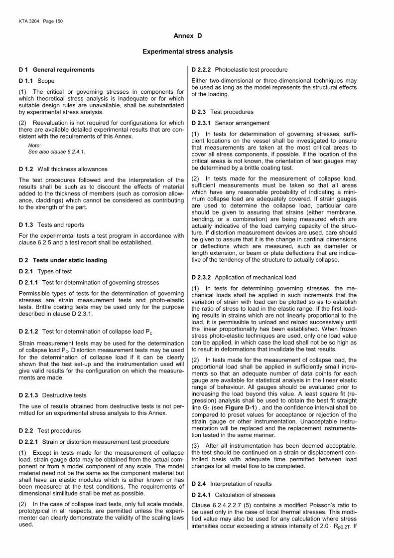
KTA 3204 Page 150
Annex D
Experimental stress analysis D 1 General requirements
D 1.1 Scope
(1) The critical or governing stresses in components for which theoretical stress analysis is inadequate or for which suitable design rules are unavailable, shall be substantiated by experimental stress analysis.
(2) Reevaluation is not required for configurations for which there are available detailed experimental results that are con-sistent with the requirements of this Annex.
Note: See also clause 6.2.4.1.
D 1.2 Wall thickness allowances
The test procedures followed and the interpretation of the results shall be such as to discount the effects of material added to the thickness of members (such as corrosion allow-ance, claddings) which cannot be considered as contributing to the strength of the part.
D 1.3 Tests and reports
For the experimental tests a test program in accordance with clause 6.2.5 and a test report shall be established.
D 2 Tests under static loading
D 2.1 Types of test
D 2.1.1 Test for determination of governing stresses
Permissible types of tests for the determination of governing stresses are strain measurement tests and photo-elastic tests. Brittle coating tests may be used only for the purpose described in clause D 2.3.1.
D 2.1.2 Test for determination of collapse load Pc
Strain measurement tests may be used for the determination of collapse load Pc. Distortion measurement tests may be used for the determination of collapse load if it can be clearly shown that the test set-up and the instrumentation used will give valid results for the configuration on which the measure-ments are made.
D 2.1.3 Destructive tests
The use of results obtained from destructive tests is not per-mitted for an experimental stress analysis to this Annex.
D 2.2 Test procedures
D 2.2.1 Strain or distortion measurement test procedure
(1) Except in tests made for the measurement of collapse load, strain gauge data may be obtained from the actual com-ponent or from a model component of any scale. The model material need not be the same as the component material but shall have an elastic modulus which is either known or has been measured at the test conditions. The requirements of dimensional similitude shall be met as possible.
(2) In the case of collapse load tests, only full scale models, prototypical in all respects, are permitted unless the experi-menter can clearly demonstrate the validity of the scaling laws used.
D 2.2.2 Photoelastic test procedure
Either two-dimensional or three-dimensional techniques may be used as long as the model represents the structural effects of the loading.
D 2.3 Test procedures
D 2.3.1 Sensor arrangement
(1) In tests for determination of governing stresses, suffi-cient locations on the vessel shall be investigated to ensure that measurements are taken at the most critical areas to cover all stress components, if possible. If the location of the critical areas is not known, the orientation of test gauges may be determined by a brittle coating test.
(2) In tests made for the measurement of collapse load, sufficient measurements must be taken so that all areas which have any reasonable probability of indicating a mini-mum collapse load are adequately covered. If strain gauges are used to determine the collapse load, particular care should be given to assuring that strains (either membrane, bending, or a combination) are being measured which are actually indicative of the load carrying capacity of the struc-ture. If distortion measurement devices are used, care should be given to assure that it is the change in cardinal dimensions or deflections which are measured, such as diameter or length extension, or beam or plate deflections that are indica-tive of the tendency of the structure to actually collapse.
D 2.3.2 Application of mechanical load
(1) In tests for determining governing stresses, the me-chanical loads shall be applied in such increments that the variation of strain with load can be plotted so as to establish the ratio of stress to load in the elastic range. If the first load-ing results in strains which are not linearly proportional to the load, it is permissible to unload and reload successively until the linear proportionality has been established. When frozen stress photo-elastic techniques are used, only one load value can be applied, in which case the load shall not be so high as to result in deformations that invalidate the test results.
(2) In tests made for the measurement of collapse load, the proportional load shall be applied in sufficiently small incre-ments so that an adequate number of data points for each gauge are available for statistical analysis in the linear elastic range of behaviour. All gauges should be evaluated prior to increasing the load beyond this value. A least square fit (re-gression) analysis shall be used to obtain the best fit straight line G1 (see Figure D-1) , and the confidence interval shall be compared to preset values for acceptance or rejection of the strain gauge or other instrumentation. Unacceptable instru-mentation will be replaced and the replacement instrumenta-tion tested in the same manner.
(3) After all instrumentation has been deemed acceptable, the test should be continued on a strain or displacement con-trolled basis with adequate time permitted between load changes for all metal flow to be completed.
D 2.4 Interpretation of results
D 2.4.1 Calculation of stresses
Clause 6.2.4.2.2.7 (5) contains a modified Poisson�s ratio to be used only in the case of local thermal stresses. This modi-fied value may also be used for any calculation where stress intensities occur exceeding a stress intensity of 2.0 ⋅ Rp0.2T. If
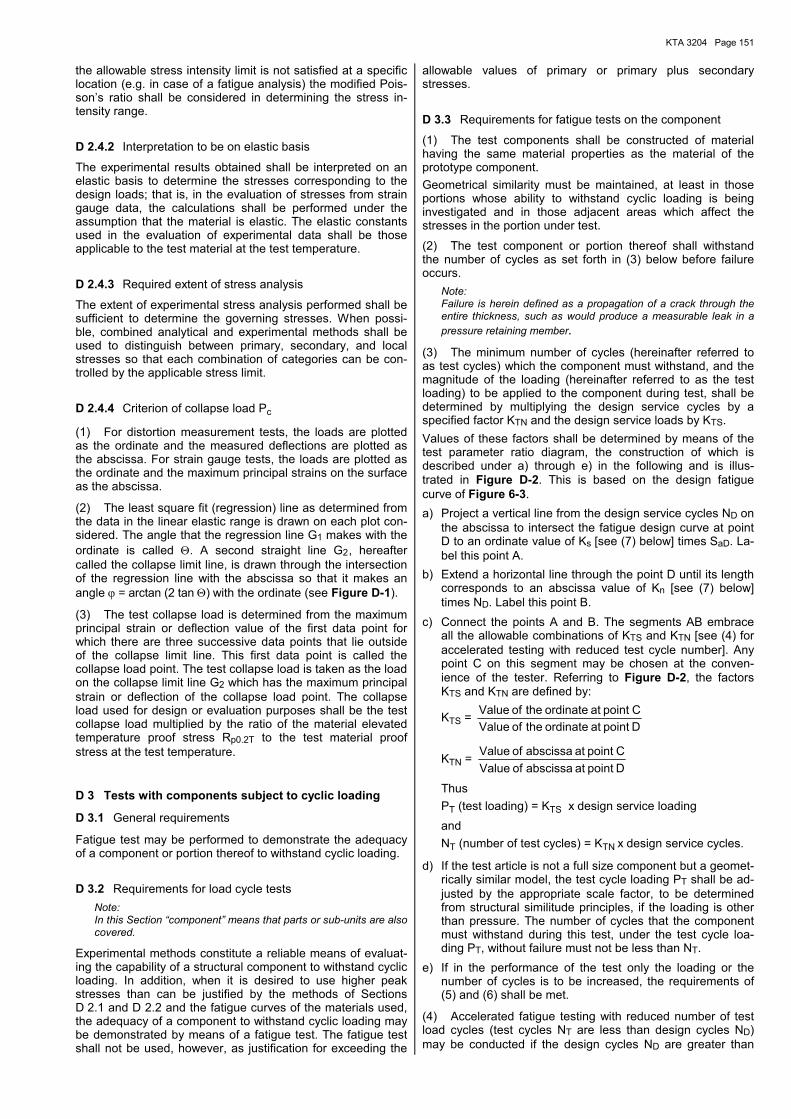
KTA 3204 Page 151
the allowable stress intensity limit is not satisfied at a specific location (e.g. in case of a fatigue analysis) the modified Pois-son�s ratio shall be considered in determining the stress in-tensity range.
D 2.4.2 Interpretation to be on elastic basis
The experimental results obtained shall be interpreted on an elastic basis to determine the stresses corresponding to the design loads; that is, in the evaluation of stresses from strain gauge data, the calculations shall be performed under the assumption that the material is elastic. The elastic constants used in the evaluation of experimental data shall be those applicable to the test material at the test temperature.
D 2.4.3 Required extent of stress analysis
The extent of experimental stress analysis performed shall be sufficient to determine the governing stresses. When possi-ble, combined analytical and experimental methods shall be used to distinguish between primary, secondary, and local stresses so that each combination of categories can be con-trolled by the applicable stress limit.
D 2.4.4 Criterion of collapse load Pc
(1) For distortion measurement tests, the loads are plotted as the ordinate and the measured deflections are plotted as the abscissa. For strain gauge tests, the loads are plotted as the ordinate and the maximum principal strains on the surface as the abscissa.
(2) The least square fit (regression) line as determined from the data in the linear elastic range is drawn on each plot con-sidered. The angle that the regression line G1 makes with the ordinate is called Θ. A second straight line G2 , hereafter called the collapse limit line, is drawn through the intersection of the regression line with the abscissa so that it makes an angle ϕ = arctan (2 tan Θ) with the ordinate (see Figure D-1).
(3) The test collapse load is determined from the maximum principal strain or deflection value of the first data point for which there are three successive data points that lie outside of the collapse limit line. This first data point is called the collapse load point. The test collapse load is taken as the load on the collapse limit line G2 which has the maximum principal strain or deflection of the collapse load point. The collapse load used for design or evaluation purposes shall be the test collapse load multiplied by the ratio of the material elevated temperature proof stress Rp0.2T to the test material proof stress at the test temperature.
D 3 Tests with components subject to cyclic loading
D 3.1 General requirements
Fatigue test may be performed to demonstrate the adequacy of a component or portion thereof to withstand cyclic loading.
D 3.2 Requirements for load cycle tests Note: In this Section �component� means that parts or sub-units are also covered.
Experimental methods constitute a reliable means of evaluat-ing the capability of a structural component to withstand cyclic loading. In addition, when it is desired to use higher peak stresses than can be justified by the methods of Sections D 2.1 and D 2.2 and the fatigue curves of the materials used, the adequacy of a component to withstand cyclic loading may be demonstrated by means of a fatigue test. The fatigue test shall not be used, however, as justification for exceeding the
allowable values of primary or primary plus secondary stresses.
D 3.3 Requirements for fatigue tests on the component
(1) The test components shall be constructed of material having the same material properties as the material of the prototype component. Geometrical similarity must be maintained, at least in those portions whose ability to withstand cyclic loading is being investigated and in those adjacent areas which affect the stresses in the portion under test.
(2) The test component or portion thereof shall withstand the number of cycles as set forth in (3) below before failure occurs.
Note: Failure is herein defined as a propagation of a crack through the entire thickness, such as would produce a measurable leak in a pressure retaining member.
(3) The minimum number of cycles (hereinafter referred to as test cycles) which the component must withstand, and the magnitude of the loading (hereinafter referred to as the test loading) to be applied to the component during test, shall be determined by multiplying the design service cycles by a specified factor KTN and the design service loads by KTS. Values of these factors shall be determined by means of the test parameter ratio diagram, the construction of which is described under a) through e) in the following and is illus-trated in Figure D-2. This is based on the design fatigue curve of Figure 6-3. a) Project a vertical line from the design service cycles ND on
the abscissa to intersect the fatigue design curve at point D to an ordinate value of Ks [see (7) below] times SaD. La-bel this point A.
b) Extend a horizontal line through the point D until its length corresponds to an abscissa value of Kn [see (7) below] times ND. Label this point B.
c) Connect the points A and B. The segments AB embrace all the allowable combinations of KTS and KTN [see (4) for accelerated testing with reduced test cycle number]. Any point C on this segment may be chosen at the conven-ience of the tester. Referring to Figure D-2, the factors KTS and KTN are defined by:
KTS = D point at ordinate the of ValueC point at ordinate the of Value
KTN = D point at abscissa of ValueC point at abscissa of Value
Thus PT (test loading) = KTS x design service loading and NT (number of test cycles) = KTN x design service cycles.
d) If the test article is not a full size component but a geomet-rically similar model, the test cycle loading PT shall be ad-justed by the appropriate scale factor, to be determined from structural similitude principles, if the loading is other than pressure. The number of cycles that the component must withstand during this test, under the test cycle loa-ding PT, without failure must not be less than NT.
e) If in the performance of the test only the loading or the number of cycles is to be increased, the requirements of (5) and (6) shall be met.
(4) Accelerated fatigue testing with reduced number of test load cycles (test cycles NT are less than design cycles ND) may be conducted if the design cycles ND are greater than
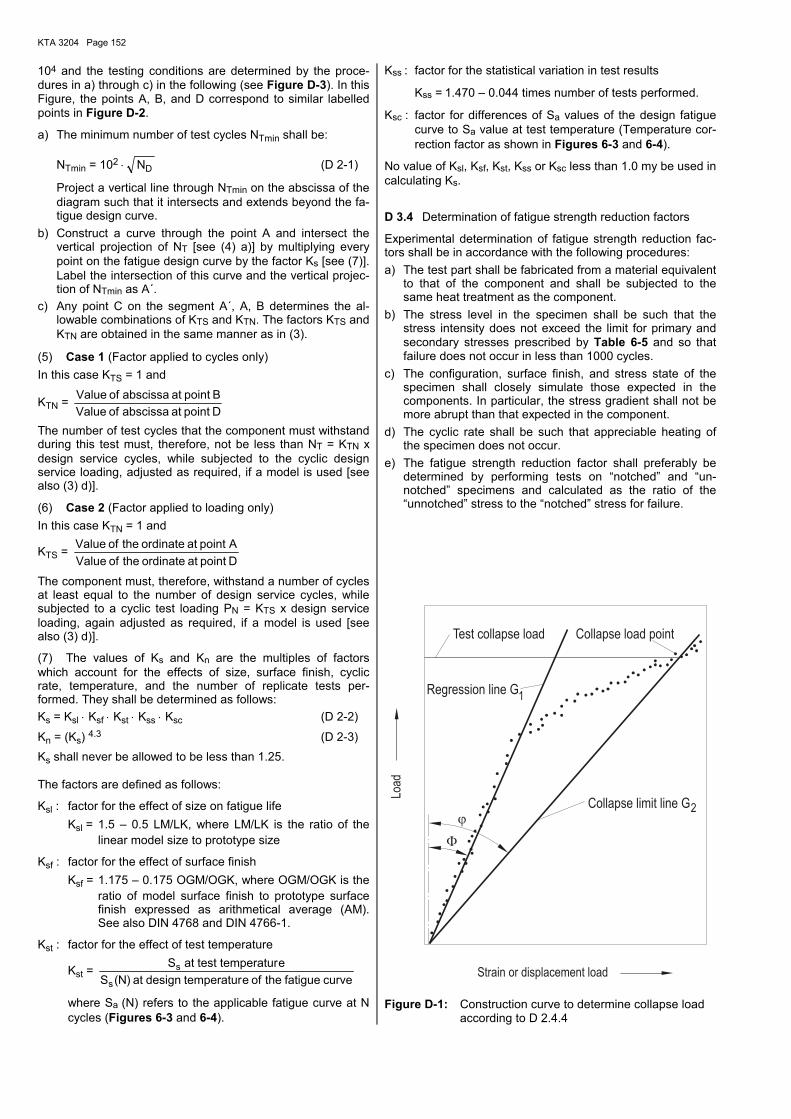
KTA 3204 Page 152
104 and the testing conditions are determined by the proce-dures in a) through c) in the following (see Figure D-3). In this Figure, the points A, B, and D correspond to similar labelled points in Figure D-2.
a) The minimum number of test cycles NTmin shall be:
NTmin = 102 ⋅ DN (D 2-1)
Project a vertical line through NTmin on the abscissa of the diagram such that it intersects and extends beyond the fa-tigue design curve.
b) Construct a curve through the point A and intersect the vertical projection of NT [see (4) a)] by multiplying every point on the fatigue design curve by the factor Ks [see (7)]. Label the intersection of this curve and the vertical projec-tion of NTmin as A´.
c) Any point C on the segment A´, A, B determines the al-lowable combinations of KTS and KTN. The factors KTS and KTN are obtained in the same manner as in (3).
(5) Case 1 (Factor applied to cycles only) In this case KTS = 1 and
KTN = D point at abscissa of ValueB point at abscissa of Value
The number of test cycles that the component must withstand during this test must, therefore, not be less than NT = KTN x design service cycles, while subjected to the cyclic design service loading, adjusted as required, if a model is used [see also (3) d)].
(6) Case 2 (Factor applied to loading only) In this case KTN = 1 and
KTS = D point at ordinate the of Value Apoint at ordinate the of Value
The component must, therefore, withstand a number of cycles at least equal to the number of design service cycles, while subjected to a cyclic test loading PN = KTS x design service loading, again adjusted as required, if a model is used [see also (3) d)].
(7) The values of Ks and Kn are the multiples of factors which account for the effects of size, surface finish, cyclic rate, temperature, and the number of replicate tests per-formed. They shall be determined as follows: Ks = Ksl ⋅ Ksf ⋅ Kst ⋅ Kss ⋅ Ksc (D 2-2)
Kn = (Ks) 4.3 (D 2-3) Ks shall never be allowed to be less than 1.25.
The factors are defined as follows:
Ksl : factor for the effect of size on fatigue life Ksl = 1.5 � 0.5 LM/LK, where LM/LK is the ratio of the
linear model size to prototype size
Ksf : factor for the effect of surface finish Ksf = 1.175 � 0.175 OGM/OGK, where OGM/OGK is the
ratio of model surface finish to prototype surface finish expressed as arithmetical average (AM). See also DIN 4768 and DIN 4766-1.
Kst : factor for the effect of test temperature
Kst = curve fatigue the of etemperatur design at )N(S
etemperatur test at S
s
s
where Sa (N) refers to the applicable fatigue curve at N cycles (Figures 6-3 and 6-4).
Kss : factor for the statistical variation in test results
Kss = 1.470 � 0.044 times number of tests performed.
Ksc : factor for differences of Sa values of the design fatigue curve to Sa value at test temperature (Temperature cor-rection factor as shown in Figures 6-3 and 6-4).
No value of Ksl, Ksf, Kst, Kss or Ksc less than 1.0 my be used in calculating Ks.
D 3.4 Determination of fatigue strength reduction factors
Experimental determination of fatigue strength reduction fac-tors shall be in accordance with the following procedures: a) The test part shall be fabricated from a material equivalent
to that of the component and shall be subjected to the same heat treatment as the component.
b) The stress level in the specimen shall be such that the stress intensity does not exceed the limit for primary and secondary stresses prescribed by Table 6-5 and so that failure does not occur in less than 1000 cycles.
c) The configuration, surface finish, and stress state of the specimen shall closely simulate those expected in the components. In particular, the stress gradient shall not be more abrupt than that expected in the component.
d) The cyclic rate shall be such that appreciable heating of the specimen does not occur.
e) The fatigue strength reduction factor shall preferably be determined by performing tests on �notched� and �un-notched� specimens and calculated as the ratio of the �unnotched� stress to the �notched� stress for failure.
1
2
Load
Strain or displacement load
Test collapse load Collapse load point
Regression line G
Collapse limit line G
Figure D-1: Construction curve to determine collapse load according to D 2.4.4
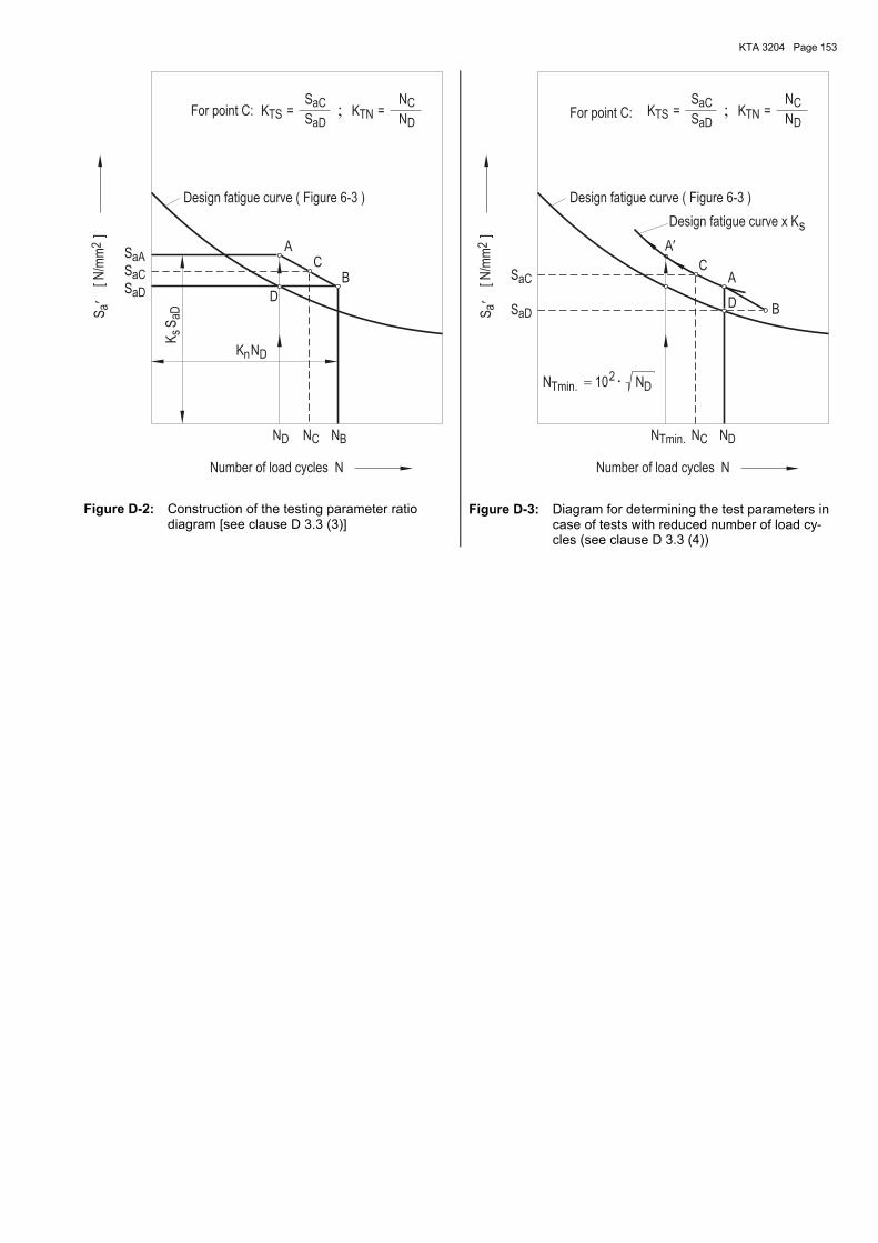
KTA 3204 Page 153
��
aD D
aC
aC
aD
TS
n
saD
CTN
D
C BD
2a
aA
K
K
Design fatigue curve ( Figure 6-3 )
K
N
N
[N/m
m]
S
Number of load cycles N
S
N
S
S
C
S
S=For point C: K
A
S
=
N
N
B
D
N
Figure D-2: Construction of the testing parameter ratio diagram [see clause D 3.3 (3)]
�
�aD
D
CTS TN
aC
aC
aD
2a
2
Tmin. D
D
C
Tmin.
N=
NN 10
K
A
BD
N
CA
N
[N/m
m]
Number of load cycles N
N
S
S=
NSK
S
Design fatigue curve ( Figure 6-3 )
For point C:
S
Design fatigue curve x Ks
�
Figure D-3: Diagram for determining the test parameters in case of tests with reduced number of load cy-cles (see clause D 3.3 (4))
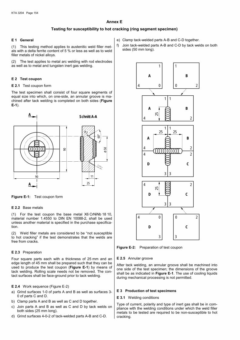
KTA 3204 Page 154
Annex E
Testing for susceptibility to hot cracking (ring segment specimen) E 1 General
(1) This testing method applies to austenitic weld filler met-als with a delta ferrite content of 5 % or less as well as to weld filler metals of nickel alloys.
(2) The test applies to metal arc welding with rod electrodes as well as to metal and tungsten inert gas welding.
E 2 Test coupon
E 2.1 Test coupon form
The test specimen shall consist of four square segments of equal size into which, on one-side, an annular groove is ma-chined after tack welding is completed on both sides (Figure E-1).
60°
11
R3
50
25
90
90
A
Schnitt A-AA
Figure E-1: Test coupon form
E 2.2 Base metals
(1) For the test coupon the base metal X6 CrNiNb 18 10, material number 1.4550 to DIN EN 10088-2, shall be used unless another material is specified in the purchase specifica-tion.
(2) Weld filler metals are considered to be �not susceptible to hot cracking� if the test demonstrates that the welds are free from cracks.
E 2.3 Preparation
Four square parts each with a thickness of 25 mm and an edge length of 45 mm shall be prepared such that they can be used to produce the test coupon (Figure E-1) by means of tack welding. Rolling scale needs not be removed. The con-tact surfaces shall be face-ground prior to tack welding.
E 2.4 Work sequence (Figure E-2) a) Grind surfaces 1-0 of parts A and B as well as surfaces 3-
0 of parts C and D. b) Clamp parts A and B as well as C and D together. c) Join parts A and B as well as C and D by tack welds on
both sides (25 mm long). d) Grind surfaces 4-0-2 of tack-welded parts A-B and C-D.
e) Clamp tack-welded parts A-B and C-D together. f) Join tack-welded parts A-B and C-D by tack welds on both
sides (50 mm long).
1
2
33
3
4 0 2
2
33
4 2
1
4
25
25
0 2
1
25
0
1 1
4
4
0
3
25
1
24
C
BA
A B
A B
D
C
D
C
D
Figure E-2: Preparation of test coupon
E 2.5 Annular groove
After tack welding, an annular groove shall be machined into one side of the test specimen; the dimensions of the groove shall be as indicated in Figure E-1. The use of cooling liquids during mechanical processing is not permitted.
E 3 Production of test specimens
E 3.1 Welding conditions
Type of current, polarity and type of inert gas shall be in com-pliance with the welding conditions under which the weld filler metals to be tested are required to be non-susceptible to hot cracking.
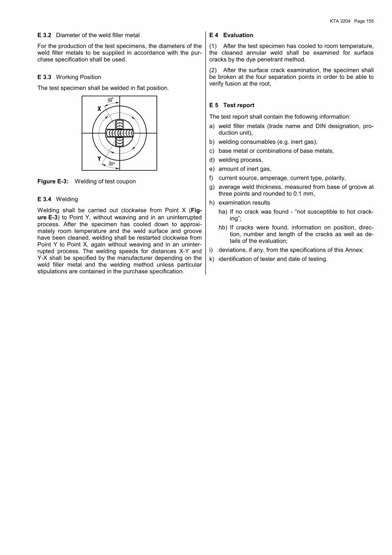
KTA 3204 Page 155
E 3.2 Diameter of the weld filler metal
For the production of the test specimens, the diameters of the weld filler metals to be supplied in accordance with the pur-chase specification shall be used.
E 3.3 Working Position
The test specimen shall be welded in flat position.
30°
30°
Y
X
Figure E-3: Welding of test coupon
E 3.4 Welding
Welding shall be carried out clockwise from Point X (Fig-ure E-3) to Point Y, without weaving and in an uninterrupted process. After the specimen has cooled down to approxi-mately room temperature and the weld surface and groove have been cleaned, welding shall be restarted clockwise from Point Y to Point X, again without weaving and in an uninter-rupted process. The welding speeds for distances X-Y and Y-X shall be specified by the manufacturer depending on the weld filler metal and the welding method unless particular stipulations are contained in the purchase specification.
E 4 Evaluation
(1) After the test specimen has cooled to room temperature, the cleaned annular weld shall be examined for surface cracks by the dye penetrant method.
(2) After the surface crack examination, the specimen shall be broken at the four separation points in order to be able to verify fusion at the root.
E 5 Test report
The test report shall contain the following information: a) weld filler metals (trade name and DIN designation, pro-
duction unit), b) welding consumables (e.g. inert gas), c) base metal or combinations of base metals, d) welding process, e) amount of inert gas, f) current source, amperage, current type, polarity, g) average weld thickness, measured from base of groove at
three points and rounded to 0.1 mm, h) examination results
ha) If no crack was found - �not susceptible to hot crack-ing�;
hb) If cracks were found, information on position, direc-tion, number and length of the cracks as well as de-tails of the evaluation;
i) deviations, if any, from the specifications of this Annex; k) identification of tester and date of testing.
KTA 3204 Page 156
Annex F
Regulations referred to in this Safety Standard (The references exclusively refer to the version given in this annex. Quotations of regulations referred to therein
refer to the version available when the individual reference below was established or issued.)
AtG Act on the Peaceful Use of Atomic Energy and the Protection against its Hazards (Atomic Energy Act) dated 23 December 1959 (BGBl. I, p. 814) as published on 15 July 1985 (BGBl. I, 1985, No. 4, p. 1565), at last amended by law dated 26 February 2008 (BGBl. I, 2008, No. 6, p. 215)
KTA 1202 (1984-06) Requirements for the Operating Manual
KTA 2201.4 (1990-06) Design of Nuclear Power Plants against Seismic Events. Part 4: Requirements for Procedures for Verifying the Safety of Mechanical and Electrical Components against Earthquakes
KTA 3201.4 (1999-06) Components of the Reactor Coolant Pressure Boundary of Light Water Reactors; Part 4: In-Service Inspections and Operational Monitoring
DIN 267-2 (1984-11) Fasteners. Technical specifications. Finishes and tolerances
DIN EN 287-1 (2006-06) Approval testing of welders for fusion welding. Part 1: Steels; German version EN 287-1:2004 + A2:2006
DIN EN ISO 14175 (2008-06) Welding consumables - Gases and gas mixtures for fusion welding and allied processes; Ger-man version EN ISO 14175:2008
DIN EN 444 (1994-04) Non-destructive testing. General principles for radiographic examination of metallic materials by X- and gamma-rays; German version EN 444: 1994
DIN EN 462-1 (1994-03) Non-destructive testing. Image quality of radiographs. Part 1: Image quality indicators (wire type). Determination of image quality value; German version EN 462-1:1996
DIN EN 462-3 (1996-11) Non-destructive testing; Image quality of radiographs; Part 3: Image quality classes for ferrous metals; German version EN 462-3:1996
DIN EN 473 (2008-09) Non-destructive testing. Qualification of NDT personnel. General principles; German version EN 473:2008
DIN EN 571-1 (1997-03) Non-destructive testing. Penetrant testing. Part 1: General principles; German version EN 571-1:1997
DIN EN ISO 643 (2003-09) Steels. Micrographic determination of the apparent grain size; German version EN ISO 643:2003 � Correction 2004-07
DIN EN 895 (1999-05) Destructive tests on welds in metallic materials. Transverse tensile test; German version EN 895:1995
DIN EN ISO 898-1 (1999-11) Mechanical properties of fasteners made of carbon steel and alloy steel. Part 1: Bolts, screws and studs; German version EN ISO 898-1:1999
DIN EN 910 (1996-05) Destructive tests on welds in metallic materials - Bend tests; German version EN 910:1996
DIN EN 970 (1997-03) Non-destructive examination of fusion welds - Visual examination; German version EN 970:1997
DIN EN ISO 1101 (2008-08) Technical drawings. Geometrical tolerancing. Tolerancing of form, orientation, location and run-out - Generalities, definitions, symbols, indications on drawings; German version EN ISO 1101:2005
DIN EN ISO 1302 (2002-06) Geometrical product specifications (GPS). Indication of surface texture in technical product documentation; German version EN ISO 1302:2002
DIN EN 1320 (1996-12) Destructive tests on welds in metallic materials. Fracture tests; German version EN 1320:1996
DIN EN 1418 (1998-01) Welding personnel. Approval testing of welding operators for fusion welding and resistance weld setters for fully mechanized and automatic welding of metallic materials; German version EN 1418;1997
DIN EN 1435 (2002-09) Non-destructive examination of welds. Radiographic examination of welded joints; German version EN 1435:1997 + A1:2002
DIN EN 1559-1 (1997-08) Founding. Technical conditions of delivery. Part 1: General; German version EN 1559-1:1997
DIN EN 1559-2 (2000-04) Founding. Technical conditions of delivery. Part 2: Additional requirements for steel castings; German version EN 1559-2:2000
DIN EN 1600 (1997-10) Welding consumables. Covered electrodes for manual metal arc welding of stainless and heat resisting steels. Classification; German version EN 1600:1997
DIN 2093 (2006-03) Disc springs; Dimensions and quality specifications / Correction 2007-07
DIN 2095 (1973-05) Helical springs made of round wire. Quality specifications for cold coiled compression springs
KTA 3204 Page 157
DIN EN ISO 2560 (2006-03) Welding consumables. Covered electrodes for manual metal arc welding of non alloy and fine grain steels. Classification (ISO 2560:2002); German version EN ISO 2560:2005
DIN ISO 2768-1 (1991-06) General tolerances; Tolerances for linear and angular dimensions without individual tolerance indications; Identical with ISO 2768-1:1989
DIN ISO 2768-2 (1991-04) General tolerances; Geometrical tolerances for features without individual tolerances indica-tions; Identical with ISO 2768-2:1989
DIN EN ISO 3269 (2000-11) Fasteners. Acceptance inspection (ISO 3269:2000); German version EN ISO 3269:2000
DIN EN ISO 3452-2 (2006-11) Non-destructive testing. Penetrant testing. Part 2: Testing of penetrant materials (ISO 3452-2:2006); German version EN ISO 3452:2006
DIN EN ISO 3452-3 (1999-02) Non-destructive testing. Penetrant testing. Part 3: Reference test blocks (ISO 3452-3:1998); German version EN ISO 3452:3-1998
DIN EN ISO 3506-1 (1998-03) Mechanical properties of corrosion-resistant stainless-steel fasteners. Part 1: Bolts, screws and studs (ISO 3506-1:1997); German version EN ISO 3506-1:1997
DIN EN ISO 3506-2 (1998-03) Mechanical properties of corrosion-resistant stainless-steel fasteners. Part 1: Nuts (ISO 3506-2:1997; German version EN ISO 3506-2:1997
DIN EN ISO 3651-2 (1998-08) Determination of resistance to intergranular corrosion of stainless steels. Part 2: Ferritic, aus-tenitic and ferritic-austenitic (duplex) stainless steels. Corrosion test in media containing sulfuric acid (ISO 3651-2:1998); German version EN ISO 3651-2:1998
DIN EN ISO 3834-1 (2006-03) Quality requirements for fusion welding of metallic materials. Part 1: Criteria for the selection of the appropriate level of quality requirements (ISO 3834-1:2005); German version EN ISO 3834-1:2005
DIN EN ISO 3834-2 (2006-03) Quality requirements for fusion welding of metallic materials Part 2: Comprehensive quality requirements (ISO 3834-2:2005); German version EN ISO 3834-2:2005
DIN EN ISO 4287 (1998-10) Geometrical product specification (GPS). Surface texture. Profile method. Terms, definitions and surface texture parameters (ISO 4287:1997); German version EN ISO 4287:1998
DIN EN ISO 5817 (2006-10) Welding. Fusion-welded joints in steel, nickel, titanium and their alloys (beam welding ex-cluded). Quality levels for imperfections (ISO 5817:2003 + Corrigendum 1:2006); German ver-sion EN ISO 5817:2007 / Correction 2007-10
DIN EN ISO 6506-1 (2006-03) Metallic materials. Brinell hardness test. Test method (ISO 6506-1:2005); German version EN ISO 6506-1:2005
DIN EN ISO 6508-1 (2006-03) Metallic materials. Rockwell hardness test. Part 1: Test method (scales A, B, C, D, E, F, G, H, K, N, T) (ISO 6508-1:2005); German version EN ISO 6508-1:2005
DIN EN ISO 6847 (2002-02) Welding consumables. Deposition of a weld metal pad for chemical analysis (ISO 6847:2000); German version EN ISO 6847:2001
DIN 8201-7 (1985-07) Synthetic mineral abrasives; Glass beads
DIN EN ISO 8249 (2000-10) Welding - Determination of Ferrite Number (FN) in Austenitic and Duplex Ferritic-Austentic Cr-Ni Stainless Steel Weld Metals (ISO 8249:2000); German version EN ISO 8249:2000
DIN EN ISO 9606-4 (1999-06) Approval testing of welders. Fusion welding. Nickel and nickel alloys (IS) 9606-4); German version EN ISO 9606-4:1999
DIN EN ISO 9692-1 (2004-05) Welding and allied processes. Recommendations for joint preparation. Part 1: Manual metal-arc welding, gas-shielded metal-arc welding, gas welding, TIG welding and beam welding of steels (ISO 9692-1:2003); German version EN ISO 9692-1:2003
DIN EN ISO 9692-2 (1999-09) Welding and allied processes. Recommendations for joint preparation. Part 2: Submerged arc welding of steels (ISO 9692-2:1998, incl. Corrigendum AC:1999); German version EN ISO 9692-2:1998 + AC:1999
DIN EN 10002-1 (2001-12) Tensile testing of metallic materials; Part 1: Method of test at ambient temperature; German version EN 10002-1:2001
DIN EN 10002-5 (1992-02) Tensile testing of metallic materials. Part 5; Method of test at elevated temperatures; German version EN 10002-5:1991
DIN EN 10025-2 (2005-04) Hot rolled products of non-alloy structural steels. Part 2: Technical delivery conditions for flat products; German version EN 10025-2:2004
DIN EN 10028-7 (2008-02) Flat products made of steels for pressure purposes. Part 7: Stainless steels; German version EN 10028-7
DIN EN 10045-1 (1991-04) Charpy impact test on metallic materials. Part 1: Test method; German version EN 10045-1:1990
DIN EN 10083-2 (2006-10) Steels for quenching and tempering. Part 2: Technical delivery conditions for non alloy steels; German version EN 10083-2:2006

KTA 3204 Page 158
DIN EN 10084 (2008-06) Case hardening steels. Technical delivery conditions; German version EN 10084:2008
DIN EN 10088-1 (2005-09) Stainless steels. Part 1: List of stainless steels; German version EN 10088-1:2005
DIN EN 10088-2 (2005-09) Stainless steels. Part 2: Technical delivery conditions for sheet/plate and strip for general pur-poses; German version EN 10088-2:2005
DIN EN 10088-3 (2005-09) Stainless steels. Part 3: Technical delivery conditions for semi-finished products, bars, rods and sections for general purposes; German version EN 10088-3:2005
DIN EN 10204 (1995-08) Metallic products; Types of inspection documents (including amendment AC1:1995); German version EN 10204:1991 + A1:1995
DIN EN 10204 (2005-01) Metallic products; Types of inspection documents; German version EN 10204:2004
DIN EN 10213 (2008-01) Steel castings for pressure vessels; German version EN 10213:2007
DIN EN 10216-5 (2004-11) Seamless steel tubes for pressure purposes. Technical delivery conditions. Part 5: Stainless steel tubes; German version EN 10216-5:2004 / Correction 2008-06
DIN EN 10217-7 (2005-05) Welded steel tubes for pressure purposes. Technical delivery conditions. Part 7: Stainless steel tubes; German version EN 10217-7:2005
DIN EN 10222-1 (2002-07) Steel forgings for pressure purposes. Part 1: General requirements for open die forgings (incl. amendment A1:2002); German version EN 10222-1:1998 + A1:2002
DIN EN 10222-5 (2000-02) Steel forgings for pressure purposes. Part 5: Martensitic, austenitic and austenitic-ferritic stainless steels; German version EN 10222-5:1999
DIN EN 10246-7 (2005-12) Non-destructive testing of steel tubes. Part 7: Automatic full peripheral ultrasonic testing of seamless and welded (except submerged arc welded) steel tubes for the detection of longitudi-nal imperfections; German version EN 10246-7:2005
DIN EN 10250-1 (1999-12) Open die steel forgings for general engineering purposes. Part 1: General requirements; Ger-man version EN 10250-1:1999
DIN EN 10250-4 (2002-02) Open die steel forgings for general engineering purposes. Part 4: Stainless steels; German version EN 10250-4:1999
DIN EN 10272 (2008-01) Stainless steel bars for pressure purposes; German version EN 10272:2007
DIN EN 10283 (1998-12) Corrosion resistant steel castings; German version EN 10283:1998
DIN EN 10302 (2008-06) Creep resisting steels, nickel and cobalt alloys; German version EN 10302:2008
DIN EN ISO 11126-7 (1999-10) Preparation of steel substrates before application of paints and related products. Specifications for non-metallic blast-cleaning abrasives. Part 7: Specification for fused aluminium oxide; Ger-man version EN ISO 11126-7:1999
DIN EN 12668-1 (2004-10) Non-destructive testing. Characterization and verification of ultrasonic examination equipment. Part 1: Instruments (incl. amendment A1:2004); German version EN 12668-1:2000 + A1:2004)
DIN EN 12668-2 (2004-10) Non-destructive testing. Characterization and verification of ultrasonic examination equipment. Part 2: Probes (incl. amendment A1:2004); German version EN 12668-2:2000 + A1:2004)
DIN EN 12668-3 (2004-10) Non-destructive testing. Characterization and verification of ultrasonic examination equipment. Part 3: Combined equipment (incl. amendment A1:2004); German version EN 12668-3:2000 + A1:2004)
DIN EN 12681 (2003-06) Founding. Radiographic examination; German version EN 12681:2003
DIN EN 13018 (2001-07) Non-destructive testing. Visual testing. General principles; German version EN 13018:2001
DIN EN ISO 13920 (1996-11) Welding - General tolerances for welded constructions - Dimensions for lengths and angles; shape and position (ISO 13920:1996); German version EN ISO 13920:1996
DIN EN ISO 14172 (2004-05) Welding consumables. Covered electrodes for manual metal arc welding of nickel and nickel alloys. Classification (ISO 14172:2003); German version EN ISO 14172:2003
DIN EN ISO 14343 (2007-05) Welding consumables. Wire electrodes, strip electrodes, wires and rods for fusion welding of stainless and heat resisting steels. Classification (ISO 14343:2002 and ISO 13343:2002/Amd 1:2006); German version EN ISO 14343:2007
DIN EN ISO 15792-1(2008-08) Welding consumables. Test methods. Part 1:Test methods for all-weld metal test specimens in steel, nickel and nickel alloys (ISO 15792-1:2000); German version EN ISO 15792-1:2008
DIN EN ISO 17633 (2006-06) Welding consumables. Tubular cored electrodes and rods for gas shielded and non-gas shielded metal arc welding of stainless and heat-resisting steels. Classification (ISO 17633:2004); German version EN ISO 17633:2006
DIN EN ISO 17641-2 (2005-09) Destructive tests on welds in metallic materials. Hot cracking tests for weldments. Arc welding processes (ISO 17641-2:2005). Self-restraint tests; German version EN ISO 17641-2:2005
KTA 3204 Page 159
DIN EN ISO 18274 (2006-05) Welding consumables. Wire and strip electrodes, wires and rods for fusion welding of nickel and nickel alloys. Classification (ISO 18274:2004 + Corr. 1:2005); German version EN ISO 18274 + AC:2005
DIN 18800-1 (1990-11) Structural steelwork. Design and construction
DIN 18800-1/A1 (1996-02) Structural steelwork. Part 1: Design and construction, Amendment A1
DIN 18800-2 (1990-11) Structural steelwork. Analysis of safety against buckling of linear members and frames
DIN 18800-3 (1990-11) Structural steelwork. Analysis of safety against buckling of plates
DIN 18800-4 (1990-11) Structural steelwork. Analysis of safety against buckling of shells
DIN 25410 (2001-04) Nuclear facilities. Surface cleanliness of structural components
DIN 25435-4 (2003-05) In-service inspections for primary coolant circuit components of light water reactors - Part 4: Visual inspection
DIN 25450 (1990-09) Ultrasonic equipment for manual testing
DIN 25475-1 (2004-05) Nuclear facilities - Operational monitoring. Part 1: Monitoring of structure-borne sound for loose parts detection
DIN 25475-2 (2001-08) Nuclear facilities. Operational monitoring. Part 2: Vibration monitoring for early detection of changes in the vibratory behaviour of the primary coolant circuit in pressurized water reactors
DIN 50125 (2004-01) Testing of metallic materials - Tensile test pieces / Correction 2004-07
DIN 50129 (1973-10) Testing of metallic materials - Testing of welding filler metals for susceptibility to cracking
DIN 51215 (1975-09) Testing of metallic materials - Wrapping test for wire. General information
AD 2000-MB B 0 (2007-05) Design of pressure vessels
AD 2000-MB B 1 (2000-10) Cylindrical and spherical shells subject to internal overpressure
AD 2000-MB B 3 (2000-10) Domed ends subject to internal or external overpressure
AD 2000-MB B 6 (2006-10) Cylindrical shells subject to external overpressure
AD 2000-MB HP 3 (2007-02) Welding supervisors, welders
AD 2000-MB W 2 (2008-02) Austenitic and austenitic-ferritic steels
DASt 012 (1978-10) Proof of safety against buckling of plates
DASt 013 (1980-07) Proof of safety against buckling of shells
TRD 303 (1991-05) Spherical shells and dished heads under internal and external pressure
TRD 306 (1977-06) Cylindrical shells under external pressure
KTA 3204 Page 160
Annex G
Literature
[1] Handbuch für das Eisenhüttenlaboratorium, Bd. 2: Die Untersuchung der metallischen Werkstoffe, Düsseldorf 1966; Bd. 5: Erg.-Bd. 1, 2 und 3, Düsseldorf 1971/1973/1975
[2] Petzold, G.: Metallkundliche technische Reihe; metallographisches Ätzen, 5. Auflage, 1976
[3] Reference-Atlas for a comparative evaluation of ferrite percentage in the fused zone of austenitic stainless steel welded joints, des International Institute of Welding: Instituto Italiano della Saldatura, Genove 1972
[4] De Long, W. T.: Welding-Journal, July 1974, S. 273-s bis 286-s
[5] Gavalis, R.: Bending Strength in the Plastic Range, Machine Design, 7/64
[6] Cozzone, F. P.: Bending Strength in the Plastic Range, Journal of Aeronautical Sciences, May 1943
[7] Bruhn, E. F.: Analyses and Design of Flight Vehicle Structures, Tri-State Offset Company, 1965, Chap. C3.
[8] Standards Reference Radiographs of Investment Steel Castings for Aerospace Applications ASTM Designation: E 192-64
[9] Criteria of the ASME Boiler and Pressure Vessel Code for Design of Analysis in Section III and VIII, Division 2.
[10] Manjoine, M. J.; Tome, R. E.: Proposed Design Criteria for High Cycle Fatigue of Austenitic Stainless Steel, Proceedings of ASME International Conference on �Advances in Life Prediction Methods�, H00255, April 18-20, 1983, pp. 51-57.
[11] Hübel, H.: Erhöhungsfaktor Ke zur Ermittlung plastischer Dehnungen aus elastischer Berechnung, Technische Überwachung 35 (1994) Nr. 6, S. 268-278
[12] McGregor Tegart, W.J.: Elements of Mechanical Metallurgy, The Macmillan Company, New York, 1966, p. 23
[13] Macherauch, E.: Praktikum in Werkstoffkunde, 10. Auflage, Vieweg, 1992, S. 119-126
KTA 3204 Page 161
Annex H (informative)
Changes with respect to the edition 1998-06 and explanations H 1 Main items of change
The present safety standard contains the following changes with respect to the previous edition: a) The scope was put more precisely for the purpose of more
clearly defining the limits between reactor coolant pres-sure boundary and RPV internals.
b) In Section 7.3 the stipulations as to the use of material test certificates to DIN EN 10204 were taken over which make possible the use of such certificates to this standard. Re-quirements for the qualification and certification of test su-pervisors and NDT operators were supplemented in con-sideration of DIN EN 473, and further adaptations to the state-of-the-art were made as regards the take-over of re-quirements for production tests on the reactor coolant pressure boundary as regards non-destructive examina-tions.
c) Section 9 �Operational monitoring and inspection� was revised. Based on an evaluation of operational experience gained with in-service inspections of RPV internals and in consideration of the possibilities to ascertain deviations from normal service function of the hold-down assembly during operation (e.g. by vibration monitoring) the re-quirements for in-service inspections were put more pre-cisely and in part be stipulated anew. For better compre-hension and improvement of clarity the requirements for tests and inspections during normal operation and antici-pated operational occurrences were comprised in sepa-rate tables.
d) The material Inconel 690 (NiCr29Fe, material no. 2.4642) was taken over in Annex W 2 as new material as an alter-native to Inconel 600 for the product form �bars�, as it has clear advantages compared with Inconel 600. In addition, several requirements in the annexes on materials were put more precisely (e.g. with respect to the heat treatments required).
e) The entire safety standard was adapted to the current state of standards to ensure the use of same definitions and uniform stipulations for the performance and evalua-tion of tests and inspections. Where required (especially in the annexes on materials), the requirements were put more precisely with reference to current standards so that the same level of safety requirements is ensured as in the former edition 1998-06 of this safety standard. As the lot sizes in the current standards �for general purpose steel� were unacceptable to KTA 3204, the pressure vessel steel standards were referenced instead of the other standards.
f) At several locations of this safety standard clearer and more precise statements were made to ensure unambigu-ity of the requirements.
H 2 Explanations to changes compared with the edition
1998-06
(1) Clause (1) of the Section �Fundamentals� was adapted to the uniform wording used in all KTA safety standards.
(2) The scope was put more precisely such that attachment welds of the RPV internals for direct attachment to the RPV, which are within a defined distance limit to the RPV (run-out length) or which represent a pressure-retaining wall of the reactor coolant pressure boundary (leakage of the reactor coolant pressure boundary in the case of failure), shall be treated to KTA 3201.3 (Fabrication) and KTA 3201.4 (In-service inspections and operational monitoring). Where none of these conditions applies, such welds shall be under the scope of KTA 3204.
(3) In Section 2 the definition of �verification of structural integrity� (from KTA 3201.1) and the definitions of �functional capability� (from KTA 2201.4) and �product form� (from KTA 3201.3) were taken over. In addition, the term �surface crack detection examination� was replaced by the more applicable term �surface examination� throughout this standard.
(4) In Section 3 the following changes were made with re-spect to the former edition of KTA 3204 (1998-06): a) The criteria for the assignment of components, sub-units
and parts of RPV internals to quality classes AS-RE 1 to AS-RE 3 described in the informative Annex of KTA 3204 (1998-06) were taken over in a more precise form.
b) In Table 3-1 clear statements were given as to the tasks and functions as well as descriptions of the guiding, cen-tering and travel limiting elements.
c) Besides the term �control rod guide thimble� the term �control rod guide tube� was added to Table 3-1 and Fig-ure 3-2.
d) The head spray cooling device was taken over in Table 3-1 and classified under quality class AS-RE 3. It was also added to Figure 3-2.
(5) The Tables 4-1 and 5-1 as well as Figure 5-1 were sup-plemented to include the new �test instructions for non-destructive testing� of clause 7.3.5.6.1 and a �materials list� not contained up to now.
(6) The definition of stress intensity in clause 6.2.1 (52) was corrected. The requirements for the determination of equiva-lent stress intensities and the equivalent stress ranges in clause 6.2.4.2.2.2 were revised for clarity and supplemented.
(7) For better comprehension the flow chart in Figure 6-5 was improved by taking over the explanations (footnotes) formerly contained in Figure 6-4.
(8) In Section 7 �Materials and material testing� the following changes were made: a) In clause 7.2.1 a new sub-clause (8) was added with the
requirement that the manufacturer has to prove the per-formance of a material appraisal, since it cannot be as-sumed that material appraisals are performed under the current conditions.
b) In clause 7.3.1 stipulations for the use of material test certificates to DIN EN 10204 (edition 2005-01) were taken over to indicate that both test certificates to the former edi-tion (1995-08 � 3.1C/3.1B) and to the current edition (2005-01 - 3.2/3.1) are recognized. Where test certificates to DIN EN 10204 (2005-01) are used, a material test cer-tificate 3.2 shall be confirmed or be established by the technical inspecting agency tasked by the authorized in-spector as per § 20 of the Atomic Energy Act.
c) In clauses 7.3.5.2 and 7.3.5.6.3, in Table 7-2 as well as in the material test sheets 4.3.2, 4.3.3 and 4.3.4 the term �hot cracking� was revised without change of contents.
d) In clause 7.3.5.3 new requirements for magnetic meas-urement of the delta ferrite content were included which may substitute the metallographic determination in the case of a delta ferrite content less than 2 %. The refer-ences to clause 7.3.5.3 in the material test sheets of An-nex A were adapted to the changed requirements (mate-rial test sheet 1.5.1, 1.5.2, 1.5.3), and in addition clearer statements as to the measurement of the delta ferrite con-tent were given in Table 8-5 and in material test sheet W 4.3.1.
e) In clause 7.3.5.5 and in at other pertinent location in KTA 3204 the requirements for testing of resistance to inter-
KTA 3204 Page 162
granular corrosion were defined such that the test is to be performed in accordance with procedure A of DIN EN ISO 3561-2. The text of this safety standard was adapted with respect to the required sensitization to cover possible ef-fects of the relevant fabrication steps.
f) The requirements for personnel performing non-destructive examinations in clause 7.3.5.6.2 were put more precisely by supplementing requirements for qualifi-cation and certification. As regards the qualification and certification of NDT operators for radiographic and ultra-sonic examinations, the minimum level required shall be level 2 to DIN EN 473. Test supervisors shall be qualified to level 3 as regards the supervision of radiographic and ultrasonic examinations. The requirement formerly con-tained in KTA 3204 that the test supervisors must be em-ployed and the NDT operators should be employed by the manufacture�s works was deleted without substitution. It is common practice that examinations are no more per-formed by the manufacturer�s personnel, but are sub-contracted to external specialized firms. The requirements for qualification and certification sufficiently specify the re-quired knowledge and experience as to the performance of non-destructive examinations.
g) Clause 7.3.5.6.3 was adapted to the current state of stan-dards and additionally be put more precisely as to the sensitivity class and the checking of penetrants as well as with respect to the testing for hot-cracking. The former Ta-ble 7-3 became obsolete due to the changed stipulations in clause 7.3.5.6.3 and was deleted. Instead of the Table requirements for the type of treatment and surface condi-tion of product forms were added.
h) Clauses 7.3.5.6.3.1, 7.3.5.6.4, 7.3.5.6.6 and 7.3.5.6.7 were revised for clearly specifying the requirements for ha) visual inspection for surface condition hb) visual examinations for detecting surface discontinuities.
In Clause 8.3.5.2.5 the term �visual examination� was substituted by �visual inspection� and in clause 8.6.4 �vis-ual check� by �visual examination�. The requirements in the material test sheets for visual inspection and visual examination were revised with a view to the changes in 7.3.5.6.6 and 7.3.5.6.7 and supplemented where required.
i) The requirements for ultrasonic and radiographic examina-tions were put more precisely in consideration of the cur-rent standards (clauses 7.3.5.6.4 and 7.3.5.6.5).
j) Clause 7.3.5.6.8 �Check for freedom of external ferrite� was supplemented to include allowable ferrite contamina-tion.
k) As regards the weld test coupons for testing welds sus-ceptible to hot cracking (Table 7-2) adaptation to the cur-rent standards could only be made in part. Since DIN EN ISO 17641-2 does not provide for cylindrical specimens, reference to DIN 50129 (1973-10) must further be made as regards the wire-flux combination. Since the edition 2006-01 of VdTÜV instruction sheet 1153 does no more refer to ring-segment specimens, the reference to this VdTÜV instruction sheet was replaced by the newly estab-lished Annex E.
l) Table 7-4 was editorially changed. Footnote 2 was added to include proof for carbon nitride linear indications.
(9) In Section 8 �Manufacture� the following changes were made: a) In clause 8.2.1 it was laid down that for the manufacture of
components, sub-units and parts of quality class AS-RE 2 and AS-RE 3 where no welding is performed, the manu-facturer�s evaluation submitted by the plant supplier will suffice.
b) In clause 8.2.3 the requirements for welders and welding supervisory personnel as well as for operators of fully
mechanized welding equipment were adapted to the cur-rent state of European standards.
c) The title of Section 8.6 and clause 8.6.1 were changed such that the hard surfacing treated in clause 8.6.4.6 is also covered.
d) The requirements were put more precisely such that the peculiarities of thermal spraying are considered (clauses 8.6.1, 8.6.2, 8.6.3, 8.6.5, 8.9.2.3).
e) The stipulations for the scope of welding procedure quali-fications with respect to the wall thickness and diameter range were adapted to AD-Merkblatt 2000 HP 2/1 in con-junction with DIN EN 288-3 (1997-10) (clause 8.6.2.6).
f) As regards the requirements for non-destructive examina-tions within production control testing, DIN EN 970 was added to cover the requirements for visual examinations (clause 8.9.1).
g) In clause 8.9.2.1.1 requirements for surfaces with re-moved temporary attachment welds and for hard-surfacing layers were added. The unchanged Table 8-8 therefore only applies to welded joints.
h) The acceptance standards for the evaluation of indications detected by ultrasonic examination and of inclusion-type defects detected by radiography (Table 8-6) were adapted to the current state of KTA safety standards by take-over of the rules contained in KTA 3211.3 (2003-11).
(10) Section 9 �Operational monitoring and inspection� was put more precisely as regards the extent, point in time and intervals of tests and inspections, and the following changes were made with respect to the former edition 1998-06 of this safety standard: a) Through reference to DIN 25435-4 (2003-05) in clause
9.3.2 �Requirements for visual examination� it is ensured that visual examinations are performed and documented to meet the requirements for the reactor coolant pressure boundary.
b) The tests and inspections to be performed during normal operation and anticipated operational occurrences were removed from Table 9-2 and 9-3. Upon evaluation of na-tional and international operating experience as well as of results of in-service inspections (including special inspec-tions) on RPV internals the test and inspection require-ments were put more precisely. The quality standard of as well as the specific knowledge gained with German PWR and BWR plants was taken into account. The selective visual examinations on RPV internals for BWR plants con-tained up to now in Table 9-4 were included in the new Table 9-5.
c) The inspection intervals for in-service inspections formerly laid down in clause 9.3.3 (3) only were put more precisely for all components to be subject to in-service inspections and taken over in Tables 9-4 and 9-5. The inspection in-tervals were laid down in correspondence with the RPV in-spection intervals and represent minimum safety require-ments. Plant-specific peculiarities have to be considered in the plant-related test and inspection sequence program to clause 9.3.3. Stipulations were included which must be included in the plant-related test and inspection sequence program.
d) Clause 9.3.4 was supplemented to include typical exam-ples of further examinations which have to be performed if particularities are detected during inspection.
e) To avoid faulty interpretation, the requirements for points in time F and G were put more precisely in Table 9-1.
f) According to the state-of-the-art the possibilities of ascer-taining deviations from the normal function of the hold-down assembly during operation were taken into account when determining the inspection intervals.

KTA 3204 Page 163
g) A selective visual examination for mechanical damage of the stand brackets in the lower spherical part of PWR RPV was taken over as new requirement.
(11) The annexes W 1 to W 6 were adapted to the current state of standards (in which case the requirements - where necessary - were adapted to the conditions of the current standards by maintaining the level of safety requirements of the edition 1998-06). The following explanations were made to the adaptations and changes made with a view to the previ-ous edition 1998-06 of this standard: a) The stipulations of clause W 1.2.2.1 on the use of the
material 1.4550 were put more precisely and limited to boiling-water reactors, since these limitations are not re-quired for PWR according to the state of science and technology.
b) In clause W 1.2.2.1 as well as in clauses W 2.2.2.1 and W 6.2.2 it was specified that besides the stipulations in the material test sheets the requirements to be met by the manufacturer laid down in clause 7.2.1 must also be satis-fied.
c) In clause W 1.2.2.4 it was specified that upon solution annealing cooling shall be effected with a sufficiently rapid cooling rate to prevent carbon nitride precipitation.
d) In Table W 1-1 the stabilizing ratio for fasteners without subsequent heat treatment was fixed to Ti/C > 7, since for this application no technical requirement exists to fix a greater ratio, and the frequency of non-metallic inclusions which repeatedly has led to problems in fastener produc-tion is reduced with this stabilizing ratio Ti/C > 7. In addi-tion, guide values for the average thermal conductivity of austenitic stainless steels were taken over into Table W 1-4 on the basis of �Stahl Eisen Sonderberichte�, No. 10/1983.
e) The requirements for ultrasonic testing of austenitic forged and rolled bars (Tables W 1-7 and W 2-10) were changed such that checking of the usability of the base metal (end-less bars) for fasteners will be made by lot-wise testing on cut-to-length test coupons.
f) The material test sheets W 1.5.1, W 1.5.2 and W 1.5.3 were adapted to the AD rules with respect to bar and wall thickness. In addition, in material test sheet W 1.5.2 fa) it was specified that ultrasonic examination shall not
only be performed on bars, but on each component (i.e. also on forgings),
fb) the lot size for tensile tests on bars was adapted to the new pressure vessel standard for austenitic bars (DIN EN 10272).
g) In the Annexes W 1, W 2 and W 6 the footnote contained in some materials test sheets was deleted according to which, upon evaluation by the manufacturer, test certifi-cate 3.1.C could be replaced by test certificate 3.1.B. For the tests marked with this footnote now acceptance test certificate 3.1.C is required in any case.
h) In material test sheet W 1.5.3 and all material test sheets of Annex W 2 the type of material structure and determi-nation of grain size was also included.
i) In clause W 2.2.2.5 the heat treatment condition for me-chanical testing was put more precisely and the perform-ance of a wrapping test to DIN 51215 for testing of deform-ability was taken over. The material Inconel 690 (NiCr29Fe) was taken over as new material in Annex W 2 which was due to the real cases of application of the product form �bars� only. In addition, the tables and material test sheets of Annex W 2 were put more precisely and supplemented. The adaptation of the tolerances in Table W 2-2 was made for the purpose of adapting to DIN EN 10302 and not for technical reasons. In clause W 2.2.2.7 require-ments for the grain size of nickel alloys were included.
k) In clause W 4.2.1 the requirement to be met for nickel alloys as to adhering to the mechanical properties as per Table W 4-5 and W 4-6 was added since DIN EN ISO 18274 does no more contain quality requirements.
In the material test sheets W 4.3.2 and W 4.3.5 a new definition for flux-cored wire was added, and in material test sheets W 4.3.3 and W 4.3.5 the application of wire-flux combinations was deleted for lack of sufficient experi-ence of application.
l) The requirement for random sample taking in Table W 5-2 was supplemented by two lines with lot sizes < 15 and be-tween 15 and 60 in correspondence with DIN EN ISO 3269, since often smaller lot sizes than those specified in DIN EN ISO 3269 are required for wear and spare parts.
m) For the purpose of more clearly specifying close toler-ances the data on chemical composition were fixed with uniform exactness at all respective locations in the an-nexes on materials.
n) The requirements for visual examination and visual in-spection in the material test sheets were revised in con-sideration of the changes in 7.3.5.6.6 and 7.3.5.6.7 and supplemented where required.
(12) Annex C was left unchanged to be able to check calcula-tions already made. However, in Section C 4.2 the calculation example was adapted to the current state of standards. A continuation of the stress ratio method was not considered purposeful since the method can be replaced by numerical methods.
(13) As the edition 2006-01 of VdTÜV-Merkblatt 1153 does no more provide for ring-segment specimens, the specifica-tions of Annex E �Testing for susceptibility to hot-cracking� in KTA 1408.1 were taken over as new Annex E to KTA 3204 to maintain level of reliability obtained.
(14) Annex F was adapted to the latest state of standards.
(15) During the procedure of changing this safety standard it was checked whether a change in the requirements for con-sideration of the influence of the fluids contained on fatigue analyses is required. Upon intense discussions a final clarifi-cation as to the requirements in KTA 3201.2 and the an-nounced check of the expert analysis and opinion report of the Reactor Safety Commission �Consideration of the fluid influence on fatigue analyses to KTA safety standards� dated 28th April 2005 (382nd meeting of the Reactor Safety Com-mission) shall be waited for with subsequent check whether a change of fatigue curves is required.