Kestrel e400i 380Vdc
22
Document No. 0704M002 Revision Status 1,0 Date March 2009 Kestrel 3kW Voltage Limiter Type 0704-3000-380 ID for Gridtie Applications 380Vdc Limiting With Two Year Warranty Installation and Maintenance Manual To report errors, omissions or improvements please write to: [email protected] or [email protected]
-
Upload
crystal-okeefe-kull -
Category
Documents
-
view
229 -
download
0
Transcript of Kestrel e400i 380Vdc

7/28/2019 Kestrel e400i 380Vdc
http://slidepdf.com/reader/full/kestrel-e400i-380vdc 1/21
Document No. 0704M002 Revision Status 1,0 Date March 2009
Kestrel 3kW Voltage LimiterType 0704-3000-380 ID for Gridtie Applications
380Vdc Limiting
With Two Year
Warranty
Installation and Maintenance Manual
To report errors, omissions or improvements please write to:[email protected] or [email protected]

7/28/2019 Kestrel e400i 380Vdc
http://slidepdf.com/reader/full/kestrel-e400i-380vdc 2/21
Document No. 0704M002 Revision 1,0 March 2009 2
Owners Notes
General Notes:

7/28/2019 Kestrel e400i 380Vdc
http://slidepdf.com/reader/full/kestrel-e400i-380vdc 3/21
Document No. 0704M002 Revision 1,0 March 2009 3
INDEX
1 Safety Warnings and Notes 4
1.1 Safety Symbols 5
2 Voltage Limiter Overview 62.1 Voltage Limiter Description
2.2 Identification and Markings2.3 Applications and uses
3 Unpacking the Voltage Limiter 73.1 Components Supplied3.2 Components not Supplied3.3 Unpacking
4 Installation Instructions 84.1 Tools Required4.2 Typical Installation Example4.3 Mounting the Controller4.4 Electrical Wiring4.5 Commissioning
5 Wire and Cable Sizing 135.1 Voltage Limiter Wiring5.2 Lightning Protection5.3 Wire Size
6 Technical specification 15
7 Trouble shooting 17
8 Maintenance 17
9 Warranty Conditions 18
Annexures
Annexure 1: Declaration of Conformity 18
Annexure 2: Kestrel Patented Voltage Limiter 19
Annexure 3: Gridtie Inverters 20
Annexure 4: Declaration of Conformity CE 21
Annexure 5: Warranty Registration 22

7/28/2019 Kestrel e400i 380Vdc
http://slidepdf.com/reader/full/kestrel-e400i-380vdc 4/21
Document No. 0704M002 Revision 1,0 March 2009 4
Disclaimer Kestrel Wind Turbines makes every effort to give accurate information in this manual and is in no way liable for any error or omission. The user of this manual assumes full responsibility and risk
We appeal to your common sense to read and apply the safety notes.Consult professional engineers and take advice if you are unsure.
This product controls high voltages that can cause severe electrical shock or death. Do not tamper with the product. Always isolate the product before removing any cover.
1 Safety and Warning NotesAccidents can easily occur and there are always dangers associated
with any type of electrical equipment. Consult installation professionalsif you are lack experience or confidence.Use good handling methods and avoid physical injury during installationand maintenance/repair procedures. Be responsible when using alltools whether manual or powered.
Electrical SafetyRead and adhere to the installation instructions for this product. Do notwork on the system when the wind turbine is running or when lightningis possible.
The wire size used for connections must be correct for the powerssupplied. The smaller the wire diameter, the higher the wire losses andtherefore the heat generated in the wire. Use correct wire sizesthroughout the installation.In general, respect the system and use common sense. Consult aqualified electrician if you are unsure.
Installation HazardsBe sure to read and adhere to the installation instructions for thisproduct. Always work carefully and have an assistant wherever
possible. Always re-check the work as you progress. Slack bolts, poorworkmanship and loose electrical connections must be avoided.
Operational SafetyIt is quite normal for the voltage limiter to become hot during certainoperation modes. This is quite normal but be aware of hightemperatures. System Checks are best carried out in calm weather
7/28/2019 Kestrel e400i 380Vdc
http://slidepdf.com/reader/full/kestrel-e400i-380vdc 5/21
Document No. 0704M002 Revision 1,0 March 2009 5
conditions. Avoid any unnecessary maintenance or inspection duringwindy weather. Be aware that internal voltages can cause a shock.
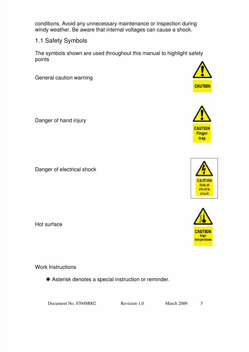
1.1 Safety Symbols
The symbols shown are used throughout this manual to highlight safety
points
General caution warning
Danger of hand injury
Danger of electrical shock
Hot surface
Work Instructions
Asterisk denotes a special instruction or reminder.
7/28/2019 Kestrel e400i 380Vdc
http://slidepdf.com/reader/full/kestrel-e400i-380vdc 6/21
Document No. 0704M002 Revision 1,0 March 2009 6
► Arrow head denotes an assembly/build instruction.
2 Voltage Limiter Overview
2.1 Voltage Limiter Description
IMPORTANT: This Voltage Limiter is solely to restrict the outputvoltage of a Kestrel Wind turbine. The product is not designed tocharge battery systems.
Sustainable/renewable energy sources such as wind turbines andhydro-generators are often connected to a gridtie inverter. Suchinverters can enter operational modes that reduce the demand ordisconnect the system from the generator. Any operational generator oralternator will exhibit high output voltages when no output is demanded.
The Kestrel Type 0704 voltage limiter uses electronic means to restrictthe incoming voltage to the inverter at a pre-designed value. Theproduct uses linear technology causing no electrical disturbance duringoperation. This quality is paramount when powering anycommunication or computer equipment.The voltage limiter is passive and uses no energy whatsoever duringnormal operation. If for any reason the generator voltage rises, thelimiter restricts this voltage rise to a maximum value. It achieves this
limiting by simulating an electrical load on the generator.
The product is housed in a steel enclosure for wall mounting. It isextremely reliable in operation and incorporates a failsafe design. Unitcooling is achieved by convection and assisting fans.
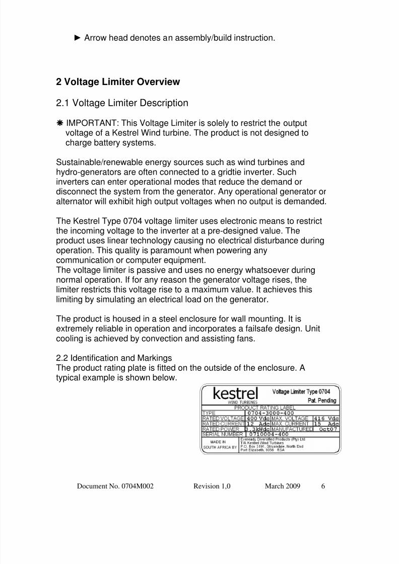
2.2 Identification and MarkingsThe product rating plate is fitted on the outside of the enclosure. Atypical example is shown below.

7/28/2019 Kestrel e400i 380Vdc
http://slidepdf.com/reader/full/kestrel-e400i-380vdc 7/21
Document No. 0704M002 Revision 1,0 March 2009 7
2.3 Applications and Uses
The Kestrel Voltage Limiter Type 0704 is primarily intended for use withthe Kestrel e400i 3kW wind turbine that has been installed with a gridconnected system using an approved gridtie inverter such as the SMAWindyBoy 3000 or the Magnetek Aurora 3600. Each application mayrequire specific additional electrical equipment. Consult the manualssupplied with this equipment.
This product is designed to monitor voltages between 0 – 1000Vdc.The Kestrel e400i 3kW turbine delivers power between 200 – 300Vdc.The load being supplied is a gridtie inverter. If the load is lost for anyreason, the voltage limiter restricts its output voltage to 380Vdc for alloperation. The inverter must therefore be able to endure an inputvoltage of 380Vdc.
3 Unpacking the Voltage Limiter
3.1 Components SuppliedThe following components are supplied.
a) Voltage Limiter assemblyb) Wall hanger
c) Installation and maintenance manual
3.2 Components Not SuppliedThe following components are necessary to complete an installation
d) Electrical crimp terminals and cablee) Wall fixing screws or boltsf) 20mm cable glands
3.3 UnpackingOpen the packaging container and check for any transit damage. Theparts contained are listed in section 3.1 and on the included packingslip. Lay out and identify the parts.

7/28/2019 Kestrel e400i 380Vdc
http://slidepdf.com/reader/full/kestrel-e400i-380vdc 8/21
Document No. 0704M002 Revision 1,0 March 2009 8
4 Installation Instructions
4.1 Tools RequiredThe following hand tools are required for the voltage limiter installation.
a) Small size electrical screwdriverb) Medium size electrical screwdriverc) Wire strippers for electrical connectionsd) Electrical crimping plierse) Tape measure for positioning
4.2 Typical Installation Examples
A typical gridtie installation is shown below. The system comprises aKestrel e300 wind turbine, voltage limiter and an alternative
manufacture gridtie inverter. Note that other electrical equipment will berequired to comply with local installation requirements. Consult thegridtie inverter manual for full installation procedures.
7/28/2019 Kestrel e400i 380Vdc
http://slidepdf.com/reader/full/kestrel-e400i-380vdc 9/21
Document No. 0704M002 Revision 1,0 March 2009 9
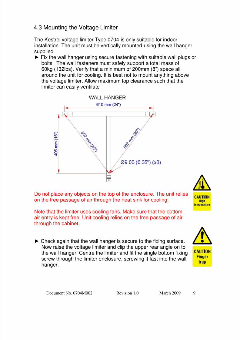
4.3 Mounting the Voltage Limiter
The Kestrel voltage limiter Type 0704 is only suitable for indoorinstallation. The unit must be vertically mounted using the wall hangersupplied.►
Fix the wall hanger using secure fastening with suitable wall plugs orbolts. The wall fasteners must safely support a total mass of60kg (132lbs). Verify that a minimum of 200mm (8”) space allaround the unit for cooling. It is best not to mount anything abovethe voltage limiter. Allow maximum top clearance such that thelimiter can easily ventilate
Do not place any objects on the top of the enclosure. The unit relieson the free passage of air through the heat sink for cooling.
Note that the limiter uses cooling fans. Make sure that the bottomair entry is kept free. Unit cooling relies on the free passage of airthrough the cabinet.
► Check again that the wall hanger is secure to the fixing surface.Now raise the voltage limiter and clip the upper rear angle on tothe wall hanger. Centre the limiter and fit the single bottom fixingscrew through the limiter enclosure, screwing it fast into the wallhanger.

7/28/2019 Kestrel e400i 380Vdc
http://slidepdf.com/reader/full/kestrel-e400i-380vdc 10/21
Document No. 0704M002 Revision 1,0 March 2009 10
4.4 Electrical Wiring
NOTE: The limiter controls high voltages and the internalcomponents can cause a shock hazard. Be aware andconsult a professional if you are in any way unsure.
Observe the Polarity at all times. Only connect +VE REDcables to +VE RED terminals and -VE BLACK cables to -VE BLACK terminals. Otherwise, equipment damage mayresult and any warranty will be invalidated.

7/28/2019 Kestrel e400i 380Vdc
http://slidepdf.com/reader/full/kestrel-e400i-380vdc 11/21
Document No. 0704M002 Revision 1,0 March 2009 11
CONSULT SECTION 5 FOR WIRE SIZERECOMMENDATIONS
The voltage limiter is provided with two pairs of +VE and-VE clearly marked terminals for "TURBINE" and
"OUTPUT" at the bottom right of the cabinet. TheTURBINE BRAKEswitch is designated “S1” and the OUTPUT CIRCUIT BREAKER isdesignated “Q1”. The turbine brake switch stops the turbine bycreating an electrical short on the turbine input. When operated, thisprevents high turbine open circuit voltages being developed.
The wind turbine must not be rotating during thisinstallation. If turbine access is not possible, short bothturbine power wires together. Observe the Polarity at all
times. Only connect +VE RED cables to +VE REDterminals and -VE BLACK cables to -VE BLACKterminals.
► PLEASE FOLLOW THE INSTRUCTIONS BELOW !
a) Arrange the wires from the turbine and the output cables ready forconnection.
b) Check that the turbine wires are shorted. Check that the output
wires are isolated from the charge controller or gridtie inverter.
c) Check that the limiter OUTPUT CIRCUIT BREAKER (Q1) isswitched OFF and that the TURBINE BRAKE SWITCH (S1) isswitched ON.
d) Connect the output wires to the limiter output terminals +VE and – VE observing polarity.
e) Connect an electrical earth wire to the marked earth screw terminalprovided.
f) Separate the turbine wires and connect the turbine negative wire tothe limiter turbine negative terminal.
g) Finally connect the turbine positive wire to the controller turbinepositive terminal.

7/28/2019 Kestrel e400i 380Vdc
http://slidepdf.com/reader/full/kestrel-e400i-380vdc 12/21
Document No. 0704M002 Revision 1,0 March 2009 12
h) Check that the turbine brake switch “S1” is ON and that the outputcircuit breaker “Q1” is off. (There is no reaction)
i) Complete the external wiring to the gridtie inverter. Follow themanufacturers instructions for this work. After all wiring is completeand secure, check that no foreign materials are inside the cabinet.
Re-install the front cover.
4.5 Commissioning
The turbine brake switch should be on and the output C/B should beoff after the installation.
The front cover has been replaced.
► Switch the brake switch off. The turbine will now activatedepending
on the wind speed. Verify that the turbine is rotating.
► Now Switch the output C/B on. The gridtie inverter will then start toinitialise. Verify that power is being supplied to the utility by theinverter. The voltage limiter fans will operate when voltage limiting istaking place. Otherwise, there is nothing to observe when the limiteris functioning.
The instructions are reversed for de-commissioning. First isolate theadditional equipment, switch the limiter output breaker off and thenoperate the turbine brake switch.
A disconnected turbine should always be shorted.

7/28/2019 Kestrel e400i 380Vdc
http://slidepdf.com/reader/full/kestrel-e400i-380vdc 13/21
Document No. 0704M002 Revision 1,0 March 2009 13
5 Wire and Cable Sizes
5.1 Voltage Limiter Wiring
Observe the Polarity at all times. Only connect +VE RED cables to +VERED terminals and -VE BLACK cables to -VE BLACK terminals.
Otherwise, equipment damage may result and any warranty will beinvalidated.
The installation must comply with local code requirements forelectrical installation. The following suggestions are made as aguideline. If you are in doubt, consult a qualified electrician.
Good wire connections are absolutely essential to avoid poor powerdelivery and high temperatures at the connection. All electricalsystems lose energy through cables resistance. The enclosure must
be directly earthed.
Use the installed cable access holes at the bottom right of thecabinet. Do not create an alternative cable entry point. Fit properelectrical glands.
5.2 Lightning protection
Proper grounding is essential to protect the system from inducedvoltages and static. The installation must comply with local
requirements for electrical installations. Ensure that the generator iselectrically connected to the mounting structure and that the structure isearthed. This is usually done by burying a 2 to 3m (6’ – 10’) length ofwater pipe (Steel or copper) horizontally, 800mm (2,5’) below theground surface. A good connection is made between the middle of thepipe and the structure. An improved method is to bury a cross of pipe,which requires a "X" shape to be excavated. The connection is made inthe centre of the cross.
Adhere to the earthing/grounding instructions for thechosen inverter. Consult the inverter manual.

7/28/2019 Kestrel e400i 380Vdc
http://slidepdf.com/reader/full/kestrel-e400i-380vdc 14/21
Document No. 0704M002 Revision 1,0 March 2009 14
5.3 Cable and Wire Size
The cable wire size from the wind turbine to the voltage limiter dependson the distance between them. Refer to the wind turbine manual for thiswire size.
The voltage limiter and the gridtie inverter are installed together. 2,5square milimetres wire will give a wire loss of less than 1% over adistance of up to 30m (100’) between the voltage limiter and theinverter.
The wire size from the turbine will almost certainly be larger than 2,5sqmm, so left over wire can be used to connect the voltage limiter and theinverter.
Wire lengths account for a double cable run (both +ve and –ve
together) being given in metric metres (m) and imperial feet (‘). Wirecross sectional area is given in metric square millimetres (sq mm) andAmerican Wire Gauge AWG.
Wire Size between the 0704 380V Voltage limiter and the Inverter(15A maximum current)
Wire Size Table for Kestrel Voltage Limiter 3kW 250Vdc 13A
One Way Distance
1% Power loss
2% Power loss
3% Power loss
20m (66ft) 4.0mm² (11) 2.5mm² (13) 1.5mm² (15)40m (130ft) 10mm² (7) 4.0mm² (11) 2.5mm² (13)

7/28/2019 Kestrel e400i 380Vdc
http://slidepdf.com/reader/full/kestrel-e400i-380vdc 15/21
Document No. 0704M002 Revision 1,0 March 2009 15
6 Technical Specification
General: Linear controlled voltage limiter to telecommunicationspecification with 3kW capability for the overvoltage protection ofsuitable series connected gridtie inverters.
Product Identification 0704-3000-380 ID
Maximum Power 3000W
Input voltage and variation (0-1kVdc)
Efficiency >99% at full load
Input frequency N/A dc input
Input power factor N/A dc input
Output Voltage Factory set (no user adjustment) 0 - 380Vdc Max.
Output voltage ripple N/A
Output voltage regulation +0% - 10%
User control Turbine brake and output isolate/circuit breaker
LED Indication None
Cooling Natural Convection with fan assist
Maximum Ambient 45deg C
IP Rating Indoor Installation only IP31
Cabinet Dimensions (wall mounting) 673Wx584Hx368D
Cabinet finish Electroplated, passivated and painted.
Product mass Limiter and wall hanger 60kg unpacked
Certification Complies with EMC requirements CIS22 Class B

7/28/2019 Kestrel e400i 380Vdc
http://slidepdf.com/reader/full/kestrel-e400i-380vdc 16/21
Document No. 0704M002 Revision 1,0 March 2009 16
7 Troubleshooting
THE KESTREL TYPE 0704 VOLTAGE LIMITER MAY BE SERIOUSLY DAMAGEDFROM POLARITY REVERSAL. (wrong connection of +ve and –ve wiring).LIMITER DEGRADATION CAN OCCUR FROM IMPROPER INSTALLATIONCAUSING OVERHEATING.
IF FOR ANY REASON THE WIND TURBINE IS DISCONNECTED, SHORT THEGENERATOR OUTPUT WIRES. THIS WILL LOAD THE GENERATOR ANDMINIMISE ROTATION.
Q The cooling fans never switch on.A The turbine brake switch is ON. The fans are automatic and only
operate when voltage limiting occurs.
Q The Output circuit breaker trips.
A There is a fault on the output cables. The output cables arereversed.
Q The limiter is always working at a high temperature.A The unit is diverting energy. The output circuit breaker has tripped.
The inverter has failed. The mains utility has failed. The inverter iswrongly programmed. Internal limiter components have failed.
Q Will I damage the limiter if I disconnect the inverter?A No, the limiter will continue to control with nothing connected to the
output. It may however become quite hot as it has to divert all theenergy from the wind turbine.
8 Maintenance
NOTE: The limiter controls high voltages and the internal components cancause a shock hazard. Be aware and consult a professional if you are in anyway unsure.
The Kestrel Type 0704 voltage limiter is designed for continuousoperation on 100% duty cycle and requires no regular part
replacement. Keep the unit clean and ensure that no foreign objectsreduce the airflow through the bottom inlet grill or the top front outlet.Clean the case only with a soft damp cloth. Do not use any form ofsolvent. This product controls and limits voltages that can cause ashock. Always take extreme care when the cover is removed. In theunlikely event of failure, the unit should be returned to the dealer ordirect to the factory for repairs.
7/28/2019 Kestrel e400i 380Vdc
http://slidepdf.com/reader/full/kestrel-e400i-380vdc 17/21
Document No. 0704M002 Revision 1,0 March 2009 17
9 Warranty
Kestrel Two Year Limited Warranty
1.0 General Terms and Conditions
1.1) The user must complete and return the Warranty Form within one month from the date ofinstallation or within three months after receipt of the Kestrel product.1.2) All requested information in the Warranty Form including site location, tower details, equipment
serial numbers and pictures must be provided.1.3) The product under warranty must be in normal use for which it is intended.1.4) The product must be installed and commissioned in accordance with the instructions provided in
the product manual.1.5) The product installation must be inspected by a registered Kestrel dealer either prior to or during
final commissioning.1.6) Kestrel retains the right to have any remedial work required during the warranty period to be
completed by any agent, dealer, re-seller or other appointment by Kestrel.1.7) Written notice of any defect must be delivered to an authorized Dealer or to the Kestrel factory
within fifteen days of the failure date.1.8) The remaining warranty period at any time is transferable.
1.9) Kestrel reserves the right to change or update this warranty at any time.
2.0 What the Warranty Covers 2.1) Kestrel warrants that the product complies to standard specification upon delivery and for a period
of 24 months after the Warranty Form registration.
2.2) Any product failure traceable to defective design, material, component or sub-assembly.
2.3) During the warranty period, Kestrel will at its sole discretion repair, replace or refund the purchaseprice of defective components or sub-assemblies.
2.4) Repaired or replaced product may be new, upgraded, re-manufactured or refurbished at the solediscretion of Kestrel.
2.5)Kestrel will provide return shipping to customers within South Africa or to the nearest port of entryfor customers outside South Africa.
3.0 What the Warranty Does Not Cover
3.1) Any Costs incurred due to the site removal and re-installation of any defective product.
3.2) Any shipping costs for product delivery to Kestrel or any appointed Dealer or alternative repairfacility.
3.3) Any equipment not manufactured by Kestrel3.4) Product that has undergone modification or tampering.3.5) Damage or loss caused by wind speeds in excess of 60m/s (134mph)3.6) Any form of abuse, misuse or vandalism3.7) Damage resulting from windstorm, lightning, hail, fire or any other insurable loss under standard
and extended coverage policies generally available for endorsement to the wind system consumer.3.8) Tower or support structure failures including any foundations.3.9) All acts of God including tornadoes and all other cyclonic windstorms.3.10) Damage due to voltage irregularities including lightning and utility system failures.3.11) Damage due to impact by flying objects or debris.3.12) Failures caused by not servicing and maintaining the product in accordance with the instructions
supplied by Kestrel
3.13) Components that in the opinion of the manufacturer have been subject to overload, mechanicalabuse, improper installation, use with any unsuitable power source, or any other non-warrantycondition.
3.14) Any damage to the product during shipping.
3.15) There is no obligation to implement any future product design changes or improvements onpreviously manufactured product.

7/28/2019 Kestrel e400i 380Vdc
http://slidepdf.com/reader/full/kestrel-e400i-380vdc 18/21
Document No. 0704M002 Revision 1,0 March 2009 18
Annexure 1: Declaration of Conformity

7/28/2019 Kestrel e400i 380Vdc
http://slidepdf.com/reader/full/kestrel-e400i-380vdc 19/21
Document No. 0704M002 Revision 1,0 March 2009 19
Annexure 2: Kestrel Patented Voltage Limiter
Kestrel Voltage Limiter Type: 0704-3000-380 ID
Sustainable/renewable energy sources such as wind turbines andhydro-generators produce uncontrolledelectrical energy. Gridtie inverters cannotendure any ovevoltage on their input. TheKestrel Type 0704 Voltage Limiterensures that the turbine is capped to amaximum voltage of 380Vdc at all times.This voltage is well within the maximumsustainable input voltage of many gridtieinverters.
The Kestrel Type 0704 voltage limiteruses electronic means to control theincoming voltage. The product usesmature technology causing no electricaldisturbance during operation. Power fromthe wind turbine is delivered through the product to the gridtieinverter. The limiter monitors the turbine voltage and suppliespower to the gridtie inverter. The inverter then processes (inverts)the incoming dc power into outgoing ac power.
Any excess energy is converted to heat in the voltage limiter. Theunit is highly efficient and allows the wind turbine to supply grid
power over the full range of incident wind speeds. Since thevoltage limiter is external to the generator, it can be sited close tothe gridtie inverter.
The product is housed in a steel enclosure for wall mounting andincludes a turbine brake switch and an output circuit breaker. It isextremely reliable in operation and incorporates a failsafe design.Unit cooling is achieved by natural convection and fan assist.Contact your Kestrel dealer for more information.
Additional components may be required to comply with certainlocal electrical codes. Consult your dealer.

7/28/2019 Kestrel e400i 380Vdc
http://slidepdf.com/reader/full/kestrel-e400i-380vdc 20/21
Document No. 0704M002 Revision 1,0 March 2009 20
Annexure 3: Gridtie Inverters
Kestrel does not manufacture gridtie inverters.The inverter that is installed must be suitable forconnection to a wind turbine. The mainrequirements for a suitable inverter are given
below.
Continuous power rating 3kWInput dc voltage range 0 – 400Vdc(minimum)
Input dc current rating 0 – 15Adc
Control algorithm Voltage/Power
Your Kestrel dealer or the factory can comment thecharacteristic of any control algorithm.
No input rectifier is necessary. The Kestrel e400i turbine and thevoltage limiter both output dc current.
Images are for illustration only. No product endorsment by Kestrelor any gridtie inverter manufacturer is implied. Consult your dealerfor recommendations on inverters.

7/28/2019 Kestrel e400i 380Vdc
http://slidepdf.com/reader/full/kestrel-e400i-380vdc 21/21
Annexure 4: Warranty Registration
Please complete and return this warranty sheet within threemonths after the product delivery date or within one month
following the commissioning date.Kestrel will be pleased to receive images of your installation!
Name of Product: _________________________________ Product Serial Number _________________________________ Delivery Date____________or Commissioning Date___________
Name and Address of Owner
________________________________________________
________________________________________________
________________________________________________
Telephone: _________________________________________
Email: _________________________________________
Installation / Site Address (GPS co-ordinates are appreciated)
_________________________________________________
_________________________________________________
_________________________________________________
Send to: Kestrel Wind Turbines, P.O. Box 3191, North EndPort Elizabeth, 6056, Eastern Cape, South Africa
Or email to: [email protected]