
Specification Guide - Engineering & Design Plastics Ltd Literature 24-01-2013/Kestrel... · . 2...
40
Specification Guide First for innovation The widest range of PVC-U and PVC-UE roofline, cladding and window finishes available in the UK Edition 4 www.kbp.co.uk
Transcript of Specification Guide - Engineering & Design Plastics Ltd Literature 24-01-2013/Kestrel... · . 2...

Specification Guide
First for innovationThe widest range of PVC-U and PVC-UE roofline, cladding and window finishes available in the UK
Edition 4
www.kbp.co.uk

2Specification Guide: Issue 5 Kestrel is a brand of Kestrel- BCE Ltd
Contents
3 Benefits of Kestrel PVC-UE & PVC-U
4 The Kestrel Range and Colours
5 Fascia Installation Details
6 Fascia Installation Details
7 Fascia Installation Details
8 Bargeboard Installation Details
9 Soffit Installation Details
10 Roofline Range & Dimensions
11 Roofline Range & Dimensions
12 Boxed End Installation Details
13 Soffit Range
14 Roofline Ventilation
15 Roofline Ventilation & Eaves Protection
16 Typical Jointing Details
17 Typical Jointing Details
18 Working with Woodgrain Products: Roofline
19 Fixing Summary - Roofline
20 White Cladding Installations
21 White Cladding Installations
22 White Cladding Installations
23 White Cladding Installations
24 White Cladding Installations
25 White Cladding Installations
26 Working with Woodgrain Products: Cladding
27 Fixing Summary - Cladding
28 Kavex Textured Cladding Installations
29 Kavex Textured Cladding Installations
30 Kavex Textured Cladding Installations
31 Fixing Summary - Kavex Cladding
32 Internal Applications for Kestrel Products
33 Windowboards & Trims
34 Window Board Range
35 Trims Range
36 10 Most Frequently Asked Questions
37 Product Characteristics
38 Product Characteristics
39 Fixing Summary - General
Cla
dd
ing
Win
dow
boar
ds&
Tri
ms
Tech
nic
alR
oo
flin
e
Contents
Con
tent
s

3
Kestrel’s popularity in the new build, specification,architectural and refurbishment sector stems fromits product reliability and wide acceptanceamongst the trade and the general public.Refurbishment programmes by housingassociations and local authorities acknowledgeKestrel products as the route to lowermaintenance costs.
Key FeaturesFlexibility A wide range of designs and styles to suit virtually everycommercial, industrial and domestic application. Withflexibility of application built in at every stage.
Durability Long-lasting, reliable products that will not rot, split, warpor crack and that are designed to resist the elements.
PracticalityNever needs painting or preserving and will stay lookinggood for years to come. Easy to specify and simple toinstall.
Good-lookingA wide variety of colours and finishes to choose from withdesigns for every application.
Quality - ISO 9001The company has a Quality Management Systemapproved by the British Standards Institute to ISO 9001(FM506475).
Environmental - ISO 14001The company has a Environmental Management Systemapproved by the British Standards Institute to ISO 14001(EMS533259).
Responsible Sourcing - BS EN ISO 6001The company has a Responsible Sourcing Systemapproved by the British Standards Institute to ISO 6001(BES 581349).
RecovinylRecovinyl facilitates the collection and recycling of PVCpost-consumer waste from the construction anddemolition sector.
Product GuaranteesKestrel’s white products are guaranteed for 20 years asstandard extendible to 35 years with our RegisteredInstaller Scheme. Woodgrains are guaranteed 10 yearsand lightgrains for 7 years provided that approvedinstallation and maintenance instructions are followed.Copies of the guarantees which relate to white and foiledproducts are available from the Kestrel marketing team.
Calcium Organic Eliminating the lead content in PVC has been a matter ofparticular concern for responsible manufacturers in ourindustry. As recommended by the European Commission,UK Government and the PVC industry’s Vinyl 2010initiative, some suppliers have already made the switch.Kestrel is among those leading the way. In fact, we believewe were the first in the UK to offer calcium organic coreand calcium organic skin in our PVC-UE. As well as futureproofing the product for our customers in case newlegislation on material usage does come into play, we arealso doing what we can now in the global drive forenvironmental protection.
Fastrack CadFastrack CAD is an online CAD database which givesarchitects and specifiers the opportunity to download DXFor DWG files. Kestrel's library of CAD drawings which isavailable on-line and can be accessed and downloadedby visiting www.kbp.co.uk
NBSThe National Building Specification (NBS) is a library ofclauses that can be selected and edited and used toproduce project specifications. Kestrel's NBS informationis available on-line and can be accessed throughwww.thenbs.com
Benefits of Kestrel PVC-UE & PVC-U
Roofline, Cladding, Windowboards & Trims
Thirty Five Year Guarantee
35EXTENDED
All W
hite
Pro
files ColourC
olo
ure
d Structura
l
5Guarantee
Guarantee15STANDARD
FM 506475
BES 581349
REGISTERED RECYCLER
Benefits
EMS 523259ISO14001

4Specification Guide: Issue 5
Roofline
Roof
line
Roofline
Fascia and Capping boardsKestrel’s extensive range of Square Leg, Ogee andBullnosed fascia boards provide the completesolution to every roofline application.
Soffit/General purpose boards & accessoriesAvailable in widths from 100mm to 600mm and in 5m lengths. Now also available with two finishededges with up to eight different foil finishes and threenew solid colour options.
Preventilated Soffit Available in Kestrel whites and woodgrain, the pre-ventilated soffit boards incorporate integral air slotsgiving 10mm and 25mm continuous ventilation.They are available in widths up to 600mm.
Kavex Textured CladdingKestrel’s latest textured shiplap and texturedfeatheredge cladding comes with 150mm & 300mmcoverage with a full range of accessories. It isavailable in White, Sand, Cream, Light Blue andLight Grey providing an effective yet stylish externalcladding solution.
Ventilation and Eaves protection SystemsAn over fascia system which provides an alternativemethod of roof void ventilation. Simple to install witheasy fit clipping joints, the system is available inBlack. Circular soffit vents are also available, inWhite and all three solid colours.
Window BoardsA wide variety of shapes and sizes available to suitall domestic and commercial window applications.
Finishing TrimsKestrel’s finishing trims are available in a selection ofcolours, shapes and sizes to suit all windowapplications. Available in 5m lengths in various packquantities.
Cladding systemsKestrel’s cladding systems can be fixed vertically,horizontally or diagonally and are available in twostyles: Shiplap with 150mm coverage and V-jointwith 100mm coverage. The system is available in allwhite and woodgrain colours.
FixingsA selection of sizes is available in a variety of coloursto suit all applications.
Kestrel PVC-UE & PVC-U extruded products are ideally suited for both domestic and commercial applications. They perform better in use than traditional alternatives, are quick and easy to install, and are virtuallymaintenance-free. When calculating whole-life costs, Kestrel’s products invariably offer a more practical andlower cost option.
ColoursKestrel has been at the forefront of productdevelopment in the PVC-UE and PVC-U buildingproducts sector for the last twenty years. Ourinnovations have helped to develop new marketsand to offer both customer and consumer agreater degree of choice. Keeping abreast ofconsumer trends for colours and textures is alsokey to meeting demand.
The current Kestrel range includes:Solid Colours: Standard White,Dove White,Brilliant White, Sand, Light Grey, Cream,Black and Brown Woodgrain foils:Mahogany, Sherwood, Blackgrain,Rosewood, Anthracite Grey woodgrain,Creamgrain, Whitegrain and Irish Oakwoodgrain. Textured solid colours: White, Cream,Sand, Light Blue and Light GreyFor a colour-matched product sample or currentKestrel Price list, please contact our samplesdepartment 01724 400440.
The Kestrel Range and Colours
Woodgrains foils
Kavex RangeMahogany - WG Blackgrain - BG
Black - BL
Sherwood - SG
Rosewood - PG
Brown - B
Sand - 1015
Cream - 9001
Light Grey - 7035
Whitegrain - WHG Creamgrain - CRG
Solid Colours
NEW NEW
Whites
Irish Oak* - IOG
White - W
Light Blue - X002
* Lightgrain
Sand - 1015
Light Grey - 7035 Cream - 9001
Anthracite Grey - AGG
Brilliant White - BW Standard White - W Dove White - DW
NEW
NEWNEW
NEW

5
Roofline, Cladding, Windowboards & Trims
Roofline
Fascia Installation Details
This section of the guide is intended to provideyou with a brief overview of the popularproducts in Kestrel’s Roofline range, wherethey can be used and the main criteria forinstallation. Pre-Installation ConsiderationsPreparation:• All access and works to comply with current and
relevant Health & Safety and Construction DesignManagement Regulation recommendations
• Clear work area in-line with best practice beforestarting work, ensuring safe scaffolding access isavailable
• Remove first row of roof tiles where necessary• Remove all existing fascia / soffit materials• Replace any un-sound / rotten timber or felt and
treat rafter ends with preservative• Maintain air path for roof ventilation
Installation considerationsInstallation considerations are intended to provide youwith need-to-know information for the core processesof product installation.
They are not intended as an exhaustive installationguide. The information presented will provide you witha valuable resource when assessing how best to useour products in your selected application.
FasciaFit directly to rafter ends using polytop nails, 2 per fixing centre max 600mm centres -65mm nails. Austenitic stainless steel (GradeA4 BS6105). Fascia is capable of load bearingin relation to light weight gutters and the firstrow of roof tiles (Eaves Tiles).Expansion gaps of 5mm per board end must beallowed for during installation.
Cover joints and Corners to be secured using lowmodulus neutral cure silicone. BS5889 Type A.
Gutter brackets to be secured directly into the boardusing stainless steel screws - 10 gauge x 25mm long(parallel thread form).
All Kestrel fascia boards 16mm and over are capableof load bearing and may be used in new-build orrefurbishment.
EavesProtector
StainlessSteelPolytopFixings2 x 65mm@ 600mmCentres 803 Vented Soffit
10mm Air Gap
Stainless Steel Polytop Fixings1 x 40mm @ 600mm Centres
StainlessSteelPolytopFixings2 x 65mm@ 600mmCentres
803 Vented Soffit10mm Air Gap
692 Soffit Channel
K16 Fascia & 9mm Vented Soffit
Typical Eaves Details
K22 Fascia & 9mm Vented Soffit
KB16 Fascia & 9mn Vented Soffit
EavesProtector
EavesProtector
StainlessSteelPolytopFixings2 x 65mm@ 600mmCentres
803 Vented Soffit10mm Air gap

6Specification Guide: Issue 5
Roofline
Roof
line
Fascia Installation DetailsTongue and Groove CladdingShiplap and Open-V cladding planks may also beused as soffit and are available in vented and non-vented versions. Vented cladding planks have a12.5mm air gap which permit 25mm continuousventilation to be achieved via the use of two rows ofvented product. Cladding planks are secured using30mm cladding pins.
• Joints for K22, K16, KB16 & K605 are availablein 600mm lengths in addition to shorter standardlengths.
• When using 018 as a bargeboard the box endpiece will need to be packed out to prevent theOgee form of the bargeboardstanding proud ofthe box end piece.
Timber FrameWhen fitting to timber frame project, be aware the soffitneeds to be large enough to carry over the top of thebrickwork line, back to the timber frame. Soffit widthsshould not exceed 300mm without additional support.
Extreme Winter Fitting Guidelines• A continuous tilting fillet must be used.• The fillet provides screw retention for the gutter
brackets and support to the top of the fascia. Itshould be securely nailed into the top of each rafter
• Plastic headed, 65mm long, austenitic stainless steel(grade A4) nails, are used to fix the fascia by nailingdirectly into rafter ends.
• 2 fixings must be used at each fixing centre, with amaximum distance of 600mm between centres.
• Fixings should utilise as much of the height of therafter end as possible, taking care not to split thetimber and ensuring full depth nail engagement.
• Gutter bracket screws should be fixed through thePVC-UE fascia into the continuous tilting fillet.
• Gutter specification and fixings should be obtainedfrom the gutter system manufacturer.
When considering the overall performance of theeaves area of a roof, it is important to include the roofdesign, the components and ultimately the impartedload from rain, snow and wind. The above guidancehas been compiled to aid the roof designer inobtaining the maximum performance from the PVC-UEfascia element.
681 TwoPart Trim
Framing tosecure soffit
Soffit over brickto timber frame
Sealant
Max distanceachievable
803 vented soffit(10mm air gap)
EavesProtector
EavesProtector
Stainless SteelPolytop Fixings2 x 65mm @600mm Centres
871/100 100mm VentedV-Joint Cladding
671/100 100mmV-Joint Cladding
Stainless SteelPolytop Fixings2 x 65mm @600mm Centres
Sarking Felt
Fix tilting fillet
Continuous tiltingfillet to full fasciaheight
Gutter bracketscrew tomanufacturer'sspecificationscrewed throughinto tilting fillet
Stainless SteelPolytop Fixings2 x 65mm @600mm Centres
Note: Spread nails overfull rafter end height
018 Fascia & 100mm V-Joint Cladding - Vented
K16 & 803 Timber Frame Detail
K16 & 803 Fascia Detail for Extreme Winters
Roof
line

7
Roofline, Cladding, Windowboards & Trims
Fascia Installation DetailsFlat Roof InstallationWhen fitting to a flat roof area, consideration must begiven to allow adequate ventilation above the insulationin order to comply with building regulations. Seeventilation section for a full explanation of ventilationrequirements.
Replacement ProjectsKestrel manufacture several designs of fascia cappingboards which can be fitted over the top of existingtimber fascias and bargeboards provided these aresound.
Any unsound or insecure timbers or rafter surfacesshould be removed and replaced before overcapping.
Fascia capping boards are available in square, bullnoseand ogee designs and fit flush to the existing soundfascias or backing boards.
Fascia capping boards also incorporate a return leg tocover the existing fascia and enclose the soffit leaving aneat finish.
All overcapping fascias can also be used for new-buildwork, but will require a minimum 12mm marine plywoodbacking board. (see Fixing Summary).
Inclined soffitsIn both new-build and replacement situations, K16 or605 fascias can be used in conjunction with inclinedsoffit details, as the return leg (36mm) is wide enough toprovide support for the soffit board.
Soffits in this situation are normally plain, such as 603,but can be detailled with cladding if desired.
In this instance, the use of over fascia ventilation isrecommended as the ventilation slots in pre-ventilatedsoffits are restricted. Alternatively a soffit with increasedventilation can be selected.
The boards should be fixed to the rafters at not greaterthan 300mm centres across the soffit width.
AIR PATH
K16Fascia
Secure torafter endswithPolynails 2 x 65mm@ 600mmCentres
903 range 25mm vented soffitto ventilate 50mm air space
Stainless Steel Polytop Fixings1 x 40mm @ 600mm Centres
EavesProtector
Stainless SteelPolytop Fixings2 x 50mm @600mm Centres
803 Vented Soffit10mm Air gap
Flat Roof Detail
605 Fascia & 9mm Vented Soffit
K16 Fascia & 9mm Inclined Soffit
603 Plain Soffit
Over FasciaVentilator
Stainless SteelPolytop Fixings2 x 65mm @600mm Centres
Stainless Steel Polytop Fixings40mm @ 600mm Centres
Roofline

8Specification Guide: Issue 5
Roofline
K16 - 16mm Bargeboard & Plain Soffit
Typical Verge Details
008 - 8mm Bargeboard to Timber Frame
605 - 9mm Bargeboard & No Soffit
Stainless Steel PolytopFixings 2 x 65mm @600mm Centres for16mm barge
Stainless Steel PolytopFixings 2 x 50mm @600mm Centres for8mm barge
Stainless Steel PolytopFixings 2 x 50mm @ 600mmCentres for 9mm barge
Fit directly togable ladder
Fit directly to gable ladder
Sealant
Fit directly togable rafter
No soffitused bargetight tobrickwork
Plain soffit board to verge
40mmPolytop pin
Bargeboard Installation DetailsBargeboardK16 16mm bargeboard should be installed using65mm Polytop nails 2 per fixing centre at maximum600mm centres. Austenitic stainless steel (grade A4BS6105).
605 9mm bargeboard should be installed using 50mmPolytop nails 2 per fixing centre at maximum 600mmcentres. Austenitic stainless steel (grade A4 BS6105).
Boards less than 16mm thick boards arerequired to be fully supported along their length.
K-Wave and K-Crest being 16mm thick should beinstalled using 65mm Polytop nails 2 per fixing centre atmaximum 600mm centres.
The joint of bargeboards meeting at a ridge should becovered using a cover joint or feature finial and securedusing Low Modulus Neutral Cure Silicone
Complementary RangesThe K16 and 605 are complememtary ranges beingthe same external shape.
This allows the 9mm barge to be used in conjuntionwith the 16mm fascia for a more cost effective solution.
The K22 and KB16 are also complememtary rangesbeing the same external shape.
This allows the 16mm barge to be used in conjuntionwith the 22mm fascia, to be a more cost effectivesolution.
NB: KB16 barge can be run into a K22 box endpiece to create a stepped box end feature.
Roof
line

9
Roofline, Cladding, Windowboards & Trims
Soffit Installation DetailsSoffitKestrel 9mm soffit boards are available in non-vented versions for use asverge soffit or as eaves soffit when other forms of eaves ventilation are tobe used. They are also available in ventilated form and can contributetowards providing the necessary roof space ventilation.
Soffit is secured at maximum 600mm centres to timber using 40mmPolytop pins, alternatively a wall side fix may be achieved using 692 SoffitChannel.
In properties where the outer skin of brickwork is level with the bottom ofthe fascia board soffit groove, the soffit may be extended over thebrickwork and clamped using timber battens secured to the rafter sides.
• Soffit widths should not exceed 300mm without additional support.• A H-section trim 691 is used to join soffit boards.• Soffits can be detailed from solid Soffit Board or Open ‘V’-Joint/Shiplap
cladding.• A Soffit Board channel can be used as a soffit location for soffits• All Open ‘V’-Joint and Shiplap cladded soffits should be fully supported
and fixed to timber bearers at max 600mm centres along the soffit length• It is recommended that cladding is detailed when designing wide soffits .
Stainless Steel Polytop Fixings1 x 40mm @ 600mm Centres
803 Vented Soffit10mm Air gap
Soffit H Section691 or 693
803 Vented Soffit10mm Air gap
803 Vented Soffit10mm Air gap
Soffit H Section691 or 693
Plain Soffit
Allow 5mmexpansiongap perboard endconcealed by691 soffitjoint trim
Mitred Soffit Corner Straight Soffit Corner
Min 10mm
Roofline

K16
x
x
16mm
25mm
22mm
36mm
K22
605
KB16
x
x
x
36mm
16mm
16mm
16mm
9mm
25mm
Code Dimension X
K22 K22/150 150mmK22/175 175mmK22/200 200mmK22/225 225mmK22/250 250mmK22/300 300mmK22/355 355mm Double NoseK22/405 405mm Double Nose
KB16 KB16/100 100mm KB16/150 150mmKB16/175 175mmKB16/200 200mmKB16/225 225mmKB16/250 250mmKB16/300 300mmKB16/405 405mm Double Nose
K16 K16/150 150mmK16/175 175mmK16/200 200mmK16/225 225mmK16/250 250mmK16/355 355mm Double LegK16/405 405mm Double LegK16/405/1.25 405mm Double Leg
KF16 KF16/150 150mmKF16/175 175mmKF16/200 200mmKF16/225 225mmKF16/250 250mmKF16/405 405mm
605* 605/100 100mm605/125 125mm605/150 150mm605/175 175mm605/200 200mm605/225 225mm605/250 250mm605/300 300mm605/405 405mm605/450 450mm605/500 500mm605/550 550mm605/600 610mm
KF16
Roofline Range
10Specification Guide: Issue 5
Roofline
Roof
line

K-Crest
K-Wave
018
x
x
x
Code Dimension X
505* 505/150 150mm
505/175 175mm
505/200 200mm
505/225 225mm
505/250 250mm
505/355 355mm
505/405 405mm Double Leg
018 018/150 150mm
018/175 175mm
018/200 200mm
018/225 225mm
018/250 250mm
018/405 405mm Double Leg
008* 008/150 150mm
008/175 175mm
008/200 200mm
008/225 225mm
008/250 250mm
008/300 300mm
008/405 405mm Double Leg
K-Wave & K-Crest
K-Wave 150mm min. coverage
K-Crest 150mm min. coverage
* These products can beused as fascia boards with aminimum 10mm marine plybacking board.
505
x
008
8mm
44mm
42mm
8mm
40mm
312mm200mm
x
18mm
Roofline Range
11
Roofline, Cladding, Windowboards & Trims
Roofline
SmallCornerJoint
Fasciajoint
SmallCorner
12Specification Guide: Issue 5
Roofline
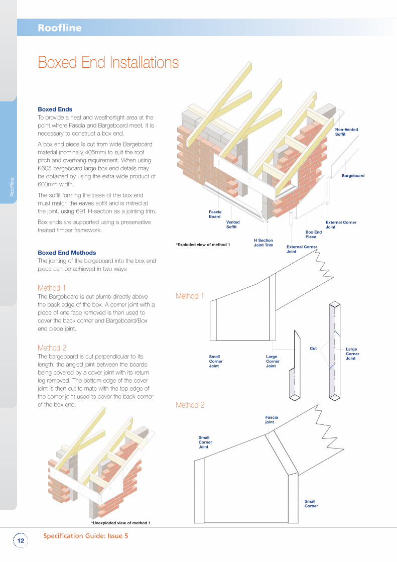
Boxed EndsTo provide a neat and weathertight area at thepoint where Fascia and Bargeboard meet, it isnecessary to construct a box end.
A box end piece is cut from wide Bargeboardmaterial (nominally 405mm) to suit the roofpitch and overhang requirement. When usingK605 bargeboard large box end details maybe obtained by using the extra wide product of600mm width.
The soffit forming the base of the box endmust match the eaves soffit and is mitred atthe joint, using 691 H-section as a jointing trim.
Box ends are supported using a preservativetreated timber framework.
Boxed End Methods The jointing of the bargeboard into the box endpiece can be achieved in two ways
Method 1The Bargeboard is cut plumb directly abovethe back edge of the box. A corner joint with apiece of one face removed is then used tocover the back corner and Bargeboard/Boxend piece joint.
Method 2The bargeboard is cut perpendicular to itslength; the angled joint between the boardsbeing covered by a cover joint with its returnleg removed. The bottom edge of the coverjoint is then cut to mate with the top edge ofthe corner joint used to cover the back cornerof the box end.
Method 1
Method 2
FasciaBoard
VentedSoffit
*Exploded view of method 1
*Unexploded view of method 1
H SectionJoint Trim
Non-VentedSoffit
Bargeboard
External CornerJoint
SmallCornerJoint
LargeCornerJoint
LargeCornerJoint
Cut
Box EndPiece
External CornerJoint
Boxed End Installations
Roof
line

Ventilation Products
13
Roofline, Cladding, Windowboards & Trims
Provision of Ventilation
Roofline Ventilation
The illustrations opposite reflect the basic ventilation requirements normallyapplicable for impermeable underlays (Type HR) . For additional informationincluding the use of vapour permeable underlays (Type LR) please refer toBS5250: 2011.
Disc and Strip VentilatorsKestrel provides circular soffit disc ventilators for eaves ventilation. These arefitted at varying centres, into 70mm diameter holes, to achieve the desiredlevel of ventilation.
Kestrel also provides a continuous ventilator strip for eaves ventilation.
This strip is manufactured from PVC-U in either 2.5m or 5m lengths givingventilation equivalent to a 25mm air gap.
The requirement to ventilate the roof space of a building to protectthe building and people who use it from the harmful effects causedby condensation is covered by ‘The Building Regulations 2000.’
Guidance on the provision of adequate ventilation is given inApproved Document C2 Resistance to Moisture (2004 edition) anddetailed in BS5250: 2011 Code of practice for control ofcondensation in buildings.
Kestrel provides a comprehensive range of products designed to comply withthe requirements of these regulations. (www.kbp.co.uk)
Kestrel 9mm soffit boards are available in non-vented versions for use asverge soffit or as eaves soffit when other forms of eaves ventilation are to beused.
They are also available in ventilated form and will contribute towards providingthe necessary roof space ventilation.
These pre-ventilated soffits are available in 10mm air gap up to 600mm wideand 25mm air gap up to 450mm wide.
All soffits are covered by Kestrel’s British Board of Agrement Certificate No.11/4835.
803 903
Provision of VentilationCold Roofs
Warm Roofs
Over 15˚ Pitch* For pitches over 35˚ or spans in excess of 10m
5*
10
10
2525
25 25
10
5
5
50
Over 15° PitchPitches of 15° or less require 25mm at eaves
15° Pitch or under* For spans in excess of 10m
All PitchesWell sealed ceiling
5*
Dimensions in millimetres.
K716 662/525
10mm Air Gap 25mm Air Gap 10mm Air Gap = 200mm centres25mm Air Gap = 85mm centres
Equivalent 25mm Air Gap
50mm
79mm80mm diameter external
70mm diameter internal
9mm
Roofline

14Specification Guide: Issue 5
Roofline
Eaves ProtectionThe Kestrel Eaves Protector K708 has been designed toprovide a long-term solution to the problems associatedwith eaves decay under the roof, including thedegradation of sarking felt and the secondary rotting ofrafter timbers and other roof structures.
Available in 1.5m, 2.55m or 4.95m lengths the Kestreleaves protection profile consists of a durable blackpigmented PVC-U profile located between the roof tilesand the PVC-UE fascia system.
Whether used on refurbishment projects or in new-buildinstallations, the traditional sarking felt finishes before thefascia and is lapped over the eaves protector. Therefore itis not exposed to the elements and is not subject todecay.
Ventilation and Eaves ProtectionA further enhancement of the idea of the eaves protectorcomes in the form of K711 an eaves protector combinedwith over fascia ventilation and bird comb. The ventilationof the roof void at eaves level is provided by an upstandon the underside of the eaves protector which sits on thetop edge of the fascia board.
The K711 product provides ventilation equivalent to a10mm continuous slot. This product is also available asK711/25 to provide ventilation equivalent to a 25mmcontinuous slot. The provision of an integral bird combprovides an effective barrier against bird infiltration into theroof void when using profiled roof tiles. If flat slate tiles areto be used the comb is readily removed.
The durability and rigidity of the eaves protectors and theload bearing features of Kestrel fascia boards are suchthat no tilting fillet is needed.
Eaves VentilationA simple means of providing ventilation over the fascia isalso available in the form of Kestrel K712 over fasciaventilation strips.
The K712 product provides ventilation equivalent to a10mm continuous slot.
This product is also available as K712/025 to provideventilation equivalent to a 25mm continuous slot.
As with the K711, this product is designed to sit directlyon top of the fascia board. Fix with 2.2mm x 50mmstainless steel annular ring shank fixing pin at every fixingcentre.
K708 Eaves Protector
K711 Over Fascia Ventilator & Eaves Protector
K712 Over Fascia Ventilation Strips
30mm GalvanisedClout Nail @ eachrafter centre
30mm GalvanisedClout Nail@ each rafter centre
125mmmin overlap
EavesProtector
2.2mm x 50mmstainless steelannular ring shankfixing pin max200mm centres
K712 10mmventilation strip
2.2mm x 50mm S/Steel annularring shank fixing pin.
30mm stainlesssteel pins @600mm centres
Sarking Felt
Sarking Felt
603 Plain Soffit
AIR FLOW
AIRFLOW
125mmmin overlap
Roofline VentilationVentilation and Eaves Proctection
Roof
line

15
Roofline, Cladding, Windowboards & Trims
Code Dimension X
603 603/100 100mm
603/125 125mm
603/150 150mm
603/175 175mm
603/200 200mm
603/225 225mm
603/250 250mm
603/275 275mm
603/300 300mm
603/330 330mm
603/400 400mm
603/450 450mm
603/500 500mm
603/550 550mm
603/600 600mm
803 803/100 100mm
803/150 150mm
803/175 175mm
803/200 200mm
803/225 225mm
803/250 250mm
803/300 300mm
803/330 325mm
803/375 375mm
803/400 400mm
803/425 425mm
803/450 450mm
803/500 500mm
803/550 550mm
803/600 600mm
903 903/150 150mm
903/200 200mm
903/225 225mm
903/300 300mm
903/400 400mm
903/450 450mm
Code Coverage
Cladding 870/150 150mm
Cladding 871/100 100mm
Soffit RangeNon-ventilated Soffit
10mm Air GapPre-Ventilated Soffit
25mm Air Gap Pre-Ventilated Soffit
12.5mm Air GapPre-Ventilated Cladding
603
803
903
871870
9mm
9mm
9mm
38mm30mm
150mm 100mm
17.5mm
17.5mm
x
x
x
30mm30mm
38mm
30mm
Roofline

Typical Jointing Details
16Specification Guide: Issue 5
Roofline
Corner Joint Installation
Butt Joint - Plan View Corner Joint - Plan View Internal Joint Plan View
Soffit Joint Installation
Internal Joint Installation
Min 10mm
Min 5mm
Min 5mm
Expansion Gapto be 5mmper Board End
Min5mm Min
5mm
ExpansiongapsMin 5mm perboard end
Expansion Gapto be 5mmper Board End
Moveforward toposition asrequired
Move forward toposition as required
Jointing of Fascia & BargeboardAll Kestrel fascia board ranges have a series ofspecifically designed accesories to complementthe size and shape of the fascia board.
These include some of the following:
• Extra Large Corner Joints (Typically 600mm for Box ends)
• Standard Corner Joints• Fascia Joints• Internal Corner Joints• End Caps
All joints should be secured using Low ModulusNeutral Cure Silicone.
Gaps to increase to 8mm per board endfor foiled products
Fascia Joint Installation
Overall min 10mmMin 5mm
Min 5mm
Expansion Gapto be 5mmper Board End
Min 10mm
Min 5mm Min 5mm
Min 5mmMin 5mm
Notch leg of oneside fascia atcorner
Roof
line

17
Roofline, Cladding, Windowboards & Trims
Typical Jointing Details
In-Line Box End OptionsIIn-line boxends can be created using the sameconstruction methods as shown previously on page 10.
It is important that the same material is used on thebarge as is used on the fascia.
This configuration is often used to a side gable wherethe gable meets a roof projection.
Fascia and bardgeboard material will need to be thesame type.
Fascia jointcut to suitbarge joint
Fasciajoint
Fasciajoint
Cornerjoint
LargeCornerjoint
Bargeboardcut to suit
Fascia jointcut to suit
Usingstandardcornerjoint cut tosuit
StandardFascia Joint
Leave 5mmexpansion gapper board end atjunctions
Fascia jointcut to suitapex joint
Method 3 Method 4
Method 1 Method 2
Apex JointApex joints are made utilising a standard fascia joint fromthe main fascia range cut to suit. e.g. for the K16 rangeitem 649/300.
Alternatively, a decorative finial (K714) can be used togive a more aesthetically pleasing finish.
Running Gables / In-Line PikesWhere fascia meets barge along a running gable, it isimportant that the same range of fascia and bargeboardis used. This will prevent a step being created.
Four typical methods are shown to the right. The exactmethod used will be dependent on roof pitch, layout etc.
In-Line Pike JunctionsIn-line pike junctions can be created using standardjoints from the relevant ranges.
Joints and bargeboards will need cutting to suit.
Fascia and bardgeboard material will need to be thesame type.
K714DecorativeFinial 350mm
Min 10mm
Roofline

Working with Woodgrain products requires slightlymodified procedures and installation processes.Overall, woodgrain products are as easy andconvenient to fit and use as most other products inthe Kestrel range. However, with a little extraknowledge and care at the preparation stage, youcan save yourself potential difficulties later on.
Kestrel’s Woodgrain foiled profiles have been extensivelytested to ensure long term weatherability and areguaranteed for use both internally and externally for a periodof 10 years. However, non-white systems have a differentpotential for heat absorption, with resultant risk of excessiveexpansion and contraction. In particular, with a Woodgrainfoiled coating, this heat absorption can be significant, withpotentially detrimental effects on long term installation.Special consideration needs to be given when installingWoodgrain products to minimise the amount of heat buildup and provide for greater amounts of expansion.
The following additional fixing details must be followed wheninstalling Woodgrain products:
Fascias/Bargeboard1. Increase expansion gap from 5mm for white to 8mm.
2. All installations to take place at ambient temperatures -between 5°C and 25°C.
3. All pre-installed products to be kept away from directsunlight, preferably indoors, at all times.
4. All joints to be made with Woodgrain corners and buttjoints.
18Specification Guide: Issue 5
Roofline
Working with Woodgrain Products: Roofline
Foiled Soffit Joint Installation Details
Foiled Fascia Joint Installation Details
Expansion Gapto be 8mmper Board End
Expansion Gap to be 8mm per Board End
Overall 16mm min.8mmmin.
8mmmin.
16mm min.
Rosewood Anthracite Grey Creamgrain Irish Oak
Mahogany Blackgrain Sherwood
Roof
line

Soffit Fixing detail Fixing type Product ref.
Cladding boards used as Soffit Fixing detail Fixing type Product ref.
Eaves Protection & OFVS systems Fixing detail Fixing type Product ref.
Fascia (thickness) Fixing detail Fixing type Product ref.
19
Roofline, Cladding, Windowboards & Trims
Fixing Summary - Roofline
8 - 10mm Fascia Capping Detail with marine/ WBP 50mm Polytop Nails SS-50Nplywood backing board 50mm Polytop Screws(12mm min)
16mm - 22mm Fascias Full replacement 65mm Polytop Nails SS-65N65mm Polytop Screws SS-65S50mm Polytop Screws
9mm Soffit Soffit bearers 40mm Polypins SS-40Precommended
100mm Open V Joint Timber soffit bearers 30mm Cladding Nails or Pin SS-30-CN or150mm Sniplap Cladding SS-30-CP
Kavex 150mm Open V Joint 20mm Cladding Trim Nails for SS-20-CNKavex 150mm Shiplap Cladding cladding trims
Kavex 300mm Shiplap Cladding Application as cladding system
K708 Eaves Protector 600mm centres 30mm Cladding Nails SS-30-CN
K711 & K711/25 200mm centres 50mm stainless steel annular SS-50Nring shank
K712 & K712/025 200mm centres 50mm stainless steel annular SS-50Nring shank
NOTE: Unless otherwise stated, all fascia/soffit fixing centres should not exceed 600mm centres
Expansion White 5mm per board endGap Foils & Colours 8mm per board end
Fixing Centres Replacement Fascia - 2 per fixing centre, max 600mm centres, 65mm polytop nails (or 65 / 50mm16mm+ x 4mm shank screws), austenitic stainless steel (grade BS6105).
Overcap fascia - 8mm+ 2 per fixing centre, max 600mm centres, 50mm polytop nails (or 40mm x4mm shank screws), austenitic stainless steel (grade BS6105).
Soffit Per fixing centre, max 600mm centres, 40mm polytop pins (or 40mm x 4mmshank screws), austenitic stainless steel (grade BS6105).
Soffit Boards Soffit wider than 300mm Soffits up to 300mm wide require no additional fixing. Soffit boards over300mm wide should be fixed at maximum 600mm centres along their length and 300mm centres across their width. Fix to adequate timber bearers.
Load Bearing Fascia 16mm+ 16mm - 22mm boards will support all eaves tiles in common usage in the UK(up 10kg load per 1m length of fascia) provided that the boards are installed within the requirements of the BBA certificate.
Fascia <16mm All fascia less than 16mm require a minimum 12mm marine plywood backing board.
Joint Fixing Low modulus neutral cure silicone BS5889 Type A.
Gutter Fixing For 16 - 22 mm boards Fix gutter brackets directly into the board using, for each bracket, at least2 x 10 gauge x 25mm long (parallel thread form) austenitic s/steel screws,ensuring that the screws penetrate the rear face of the board and that the bracket spacings do not exceed one metre.
Gutter Fixing For 9mm boards For the 9 mm board, gutter brackets are screwed through the fascia board onto rafter feet or other timber support.
General
Roofline

20Specification Guide: Issue 5
Cladding
Cla
ddin
g
Specifying White Cladding InstallationsKestrel’s cladding systems are ideal for a wide variety ofinternal and external applications. The system is offeredcomplete with all trims, fixings and components to ensure ahigh quality, aesthetically appealing finish. Cladding is an idealmeans of covering large areas with a durable, maintenancefree solution which will stay looking good for years. It neverneeds painting and is highly suitable for areas where futureaccess could prove difficult or costly. The design featureswithin the system mean that cladding offers a visuallyappealing alternative to traditional materials, whether indomestic or commercial applications.
Popular products within the cladding range and the principalelements of installation are detailed here.
TECHNICAL CONSIDERATIONS - InstallationThe Kestrel co-extruded PVC-U`E cladding system is suitablefor horizontal, vertical and diagonal fixing, as a decorative &protective external facing, over a timber stud or masonry wall.
When used over a sheathed timber stud frame or over amasonry or block substrate, the cladding should be fixed topreservative treated, good quality timber battens (measuringnot less than 19mm by 38mm) rigidly fixed to the substrate at600mm centres or closer.
Installation takes place by fixing trims around the periphery ofthe area to be clad followed by installation of the claddingplanks.
Planks are fixed using stainless steel annular ring shank nailspositioned in the groove which runs along the length of thecladding plank. Nailing takes place from the centre of eachplank working outwards.
Subsequent planks are fitted over the preceding planksensuring that the tongue-and-groove joint is firmly closed sothat the nail heads are concealed by the overlap. To avoiddistortion in service, care should be taken not to install thecladding in extremes of temperature (i.e. below 5°C or above25°C) and to allow adequate expansion gaps of 5mm perplank end for expansion.
The cladding must be installed to provide a minimumventilated air space of 19mm between the cladding and thebacking wall. This satisfies both NHBC requirement for aminimum 10mm wide ventilation cavity and the Foundation15 clause for a minimum 19mm cavity to be maintainedbetween claddings and sheathing.
Horizontal battens used to support trims at the base ofinstallations or at window heads, require 10mm diameterdrainage holes at 1000mm centres.
Horizontal Cladding
Diagonal Fixing
6812-partUniversalTrim
682UniversalTrim
Cladding
Starter Trim
Vapourpermeablewater barrier
Vapourpermeablewater barrier
19mm x 38mmbatten
4mm x 30mm Drainage SlotsMax 1000mm centres
19mm x 38mmbatten
600mmmax
425mmmax
682UniversalTrim
Cladding

White Cladding InstallationsWhen cladding is used in exposed locations (eg buildingsabove 10 metres in height, buildings on unprotected sitesor in open countryside) it is recommended that battenspacing be reduced, particularly at the corners of thebuilding, in order to increase the resistance to windsuction. the cladding is suitable for use above ground-floor level, and at ground-floor level in private areas wherethere is some incentive to exercise care.
It is not recommended for use at ground-floor level inpublic areas where it may be exposed to vandalism andgeneral misuse. PVC-UE cladding installations are not air,water or water vapour tight. When used on timber studwalls the product must be backed by a breathermembrane acting as a vapour-permeable water barrier,incorporated behind the cladding under the supportingbattens.
This barrier must meet the requirements of BS4016: 1972and have a vapour resistance less than 0.6 MNsg-1 when calculated from results carried out at25°C and a relative humidity of 75%, in accordance withBS3177: 1959.
Where the product is used as a decorative facingattached to weathertight masonry walls, a water barrier isnot necessary as the amount of water that will penetratethe cladding will be small and will not have an adverseeffect on the wall.
Behaviour in relation to fireWhen tested to BS476: Part 6: 1981 Kestrel white PVC-UE cladding planks achieved a fire propagationindex of 15.4 with sub indices and of 7.6, 6.4 and 1.4respectively.
Kestrel PVC-UE cladding is suitable for use as claddingon the external walls of buildings less than 20m in height(England & Wales) or 15 metres in height (Scotland)provided that the wall is 1 metre or more from the relevantboundary.
The product is suitable for use on the external walls ofbuildings in Northern Ireland less than 15 metres in heightprovided the wall is 1 metre or more from the relevantboundary, but excluding use on buildings of purposegroup VII (assembly buildings) having more than onestorey, at situations up to 7.5m above the finishedsurface of any adjoining roof or other part of the buildingto which persons have access.
The product is suitable for use as a cladding on theexternal walls of buildings 20 metres or more in height(England & Wales) or 15 metres or more in height(Scotland) provided that the wall is 1 metre or more fromthe relevant boundary and the cladding does not extendhigher than 20 metres (England & Wales) or 15 metres(Scotland).
21
Roofline, Cladding, Windowboards & Trims
Cladding
Vertical Cladding
600mmmax
Vapourpermeablewater barrier
19mm x 38mm batten
682UniversalTrim
Cladding
The product is suitable for use on external walls of buildings inNorthern Ireland which are 15 metres or more in height providedthe wall is 1 metre or more from the relevant boundary and thecladding does not extend higher than 15 metres, but excluding useon buildings of purpose group VII (assembly buildings) having morethan one storey, at situations up to 7.5 metres above the finishedsurface of any adjoining ground, or of any adjoining roof or otherpart of the building to which persons have access.
When tested in accordance with BS476: Part 7: 1987, the whiteco-extruded material achieved a Class 1Y rating.
Although the surface spread of flame across the surface of the PVCis limited, the material does tend to char and may fall away whenexposed to fire. Due consideration should always be given to anycombustible material behind the cladding, which may becomeexposed in the event of a fire.
PVC cladding installed over timber framing now carries BRE A+rating. This allows the specifier to claim the maximum three pointsavailable under the CSH for just such an external wall system.
Permissable dynamic wind pressures (Pa)
Length of fixing nail (mm) Cladding Profile
100mm Open-V 150mm Shiplap
30 2650 1750
25 1750 1150

22Specification Guide: Issue 5
Cladding
Trim Locations and Installation
Trims Installation
Starter and Drip Trim - Horizontal Installation Starter Trim - Vertical Installation
White Cladding Installations
A 674 Drip TrimB 675 Internal Corner TrimC 676 Centre Joint TrimD 677 External Corner TrimE 678 150mm Shiplap Cladding Butt JointF 679 100mm Open-V Cladding Butt JointG 680 2-Part External Corner TrimH 681 2-Part Top Edge TrimI 682 Universal TrimJ 683 Starter Trim
H
B
H
JC IJ&A
EorF
Vapour permeable barrier
20mm Cladding Trim Nail
Treated Timber batten
DorG
I
NB. Universal channel must be pre-slotted to allow for drainage
Vapour permeable barrier
Treated Timber batten
20mm Cladding Trim Nail
Cla
ddin
g

23
Roofline, Cladding, Windowboards & Trims
Trims Installation
Universal Channel- General Edge Installation 2-Part Top Edge Trim - Vertical Installation to Soffit
Centre Joint Trim Installation Universal Edge - Vertical Installation
White Cladding Installations
2-Part Top Edge Trim - Horizontal Installation 2-Part Top Edge Trim Installation to Window Cill
Vapour permeable barrier
20mm Cladding Trim Nail
Expansion gap
Expansion gap
PVC-UE soffit
20mm Cladding Trim Nail
Vapour permeable barrier
Vapour permeable barrier
20mm Cladding Trim Nail
Expansion gap
PVC-UE soffit
65mm Polytop screw & plug
Expansion Gap20mm Cladding Trim Nail
Packing Piece
30mm Cladding Pin
Vapour permeable barrier
Treated Timber batten
Expansion Gap
Packing (cut from offcut)
Treated Timber batten
30mm Cladding Pin
Vapour permeable barrier
Vapourpermeablebarrier
Expansion gap
20mmCladdingTrim Nail
Cladding

24Specification Guide: Issue 5
Cladding
External Corner - Horizontal Installation External Corner - Vertical Installation
2-Part External Corner - Horizontal Installation 2-Part Corner - Vertical Installation
Internal Corner - Horizontal Installation Internal Corner - Vertical Installation
White Cladding Installations
Expansion gap
20mm Cladding Trim Nail
Vapour permeable barrier
Expansion gap
Packing Piece
20mm Cladding Trim Nail
30mm Cladding Pin
Vapour permeable barrier
Expansion gap
20mm Cladding Trim Nail
Vapour permeable barrier
Expansion gap
Packing Piece
20mm Cladding Trim Nail
30mm Cladding Pin
Vapour permeable barrier
Expansion gap
20mm Cladding Trim Nail
Vapour permeable barrier
Expansion gap
20mm Cladding Trim Nail
Vapour permeable barrier
Cla
ddin
g

25
Roofline, Cladding, Windowboards & Trims
Cladding System
670/150
671/100
682 681
674
677
675 676
680 683
678 679
150mmcoverage
44mm
38mm
29mm
13mm
17.5mm
36mm
40mm
100mmcoverage
20mm 49mm
17.5mm
Variable External Angle - Horizontal Installation Variable Internal Angle - Horizontal Installation
White Cladding Installations
Expansion gap
PVC-U Flexi-angle
20mm Cladding Trim Nail
Vapour permeable barrier
Expansion gap
PVC-U Flexi-angle
20mm Cladding Trim Nail
Vapour permeable barrier
Cladding

26Specification Guide: Issue 5
Cladding
Working with Woodgrain Products: Cladding
Working with Woodgrain cladding requires some modifiedprocedures and installation processes. The followingfixing details must be followed when installing Woodgraincladding products:
1. Allow a minimum of 50mm air space behind the backof all cladding installations.
2. Using the Universal Channel or Starter Trim with BattenCover at both the top and base of each cladding face,allow a 10mm air gap at the top and bottom of eachcladding unit in order to generate air flow behind theinstallation. When installing cladding vertically the useof counter battens is required.
3. Install 5m (max.) cut lengths and fix firmly at the centreof each cut length with Cladding pins asrecommended for white profile. All subsequent fixings,at maximum 400mm centres from the central fixingpoint, to be pre-slotted with a 3mm x 10mm slot andfixed with a large headed nail as recomended for whiteprofile ie stainless steel annular ringshank nails - 2mmshank diameter of 30mm length
4. Jointing of boards to be made with 676 cover jointtrim, allowing an 8mm expansion gap at every boardend.
5. Installations to take place at ambient air temperature -between 5°C and 25°C.
6. All pre-installed products to be kept stored away fromdirect sunlight, preferably indoors, at all times.
7. All end finishing cover strips etc. should allow an 8mmexpansion gap between the end of the cladding profileand the cover stop.
These precautions will allow airflow behind the claddingwhich helps to reduce excessive heat build-up.
They also allow a free expansion and contraction of theprofile along the profile length from a central fixed point.Expansion gaps at joints and finishing strips also allow forfreedom of expansion.
50mm x 38mm(or 2 x 25mm x 38)battens
681 TopEdge Trim
25mm x 38mmbattens
WoodgrainCladding
2.5mm x 10mmFixing Slot400mm
max
Allow 8mmexpansion
gap perboard end
Allow 8mmexpansion
gap perboard end
Installation Detail Vertical Cladding (counter batten)
Installation Detail - Horizontal Cladding
Mahogany Blackgrain Sherwood Rosewood
Cla
ddin
g

Fire Rating White - 6 mm Class 1Y
Battens White plain Minimum 19mm x 38mm (25mm x 38mm recommended)cladding
Foiled cladding Minimum 50mm x 38mm (or 2 x 25mm x 38mm)
Ventilation White Allow a minimum of 19mm ventilated air space behind the back of all cladding installations. This satisfies the NHBC requirement for a minimum 10mm wide ventilation cavity to be maintained between claddings and sheathing.
Foils Allow a minimum of 50mm ventilated air space behind the back of all claddinginstallations
Expansion Gap White 5mm per board end
Foils 8mm per board end
Joint Fixing Low modulus neutral cure silicone BS5889 Type A
Installation To be installed between 5°C & 25°C temperaturesTemperature
General
Fire Rating
27
Roofline, Cladding, Windowboards & Trims
Fixing Summary - White and Foiled Cladding
Batten fixings into masonry: Hammer screws into steel: Self-tapping screws into timber: Plated woodscrews.
Cladding fixings 30mm stainless SS-30-CN or SS-30-CPsteel Cladding Nails.
Trim fixings 20mm stainless SS-20-CNsteel Nails.
Breather membrane To be positioned behind the batten system against the substrate.
Fixing Details
CLADDING: PRODUCT 5M LENGTHS REQUIRED COVERAGECODE: PER SQUARE METRE: PER LINEAR METRE:
Open V Joint Cladding 671/100 2.0 0.1m ²
Shiplap Cladding 670/150 1.4 0.15m ²(150mm profile)
Area Calculations
CLADDING: PRODUCT CODE: BATTEN / FIXING CENTRE: PRODUCT CODE:
White 671/100 & 670/150 1 per fixing centre, SS-30-CN or SS-30-CPmax 600mm centres
Foils 671/100 & 670/150 1 per fixing centre, SS-30-CNmax 400mm centres
All fixings to be A4 marine grade, austenitic stainless steel (grade BS6105)
- Ensure cladding batten system is fully supported cladding system
- Fix at recommended fixing centres
- Always detail a suitable secondary waterproofing material (EXAMPLE: Vapour permeable breather membrane tomaintain a watertight structure
- The membrane should be positioned on the external face of the insulation between the insulation and the cladding
- Maintain the correct statutory airspace behind the cladding system
If Fixing Insulation Behind Important Points Which Must Always Be Observed:
Fixing Centres
Cladding

28Specification Guide: Issue 5
Cladding
Kavex Textured Cladding InstallationsFor Kavex textured cladding, standard fitting instructions can be followed.However, due to the differing sizes and colours available in the Kavex range,slightly modified batten fixings are required. Where required, ensure breathermembrane is positioned beneath the batten system against the substrate.
Battens• Set out and fix 25mm x 38mm tannalised battens vertically.• Ensure battens are parallel straight and level.• Fix battens to the substrate at 300mm maximum centres.
(600mm for 150mm single planks)• Fix a tannalised batten along the top of the installation.• No batten is needed along the base of the cladding system because it relies
on this opening to dispel excess moisture and to be used as a point ofventilation.
Battens• Fix the starter trim to the battens at the base of the installation with 20mm A4
stainless steel nails.• The starter trim is designed to locate the first cladding plank.• Measure and cut to size the vertical universal trim or corner trim notch out at
the rear of the trim.• Ensure that the trim is straight and plumb and fix onto batten with A4 20mm
stainless steel fixings at 250mm-300mm intervals.• Trims are designed to take up expansion - ensure a 5mm gap between
board edges/ends and trim stops for White cladding and 8mm for RAL9001,RAL1015, RAL7035 and X002.
• Note there are two part versions of the vertical trims for use with horizontaland vertical cladding applications.
• Measure, cut and fix the top edge trim male extrusion to the top of theinstallation between the two vertical trims. Ensure you notch out the rear ofthe vertical trim to accommodate the male top edge extrusion.
• The installation is now ready to accept the first cladding plank.• Measure first cladding plank ensuring that there is the correct gap left on
either end of the plank for expansion.• Before fixing plank locate groove section of the cladding plank into the
location lip of the starter trim.• Ensure plank is straight and level using a spirit level.• Fix plank to each batten centre using A4 30mm stainless steel nails or 8
–gauge x 30mm stainless steel countersunk headed screws.• Ensure fixings pass through nail/screw guideline groove as the boards are a
concealed fix.• Locate second board, ensure groove of second board covers the tongue of
the first board fully as not to show nail/screw heads.• Follow this procedure until you reach the top of the installation, ensuring that
each board is located properly.• Ensure the installation is checked for level every three boards.• Measure width of last board.• Cut down last board and use the off cut tongue of the board as packing
material. This will be spot glued (Cynoacrylate adhesive) to the back of thelast cladding plank and then nailed through into the top batten once located.
• Locate top cladding plank & fix through plank into top batten.• Cut and snap on female part of trims to the vertical male extrusion ensuring
that the trim finishes at the top of the installation.• Measure cut and snap on the top edge trim ensuring that the trim is fixed
between the two vertical trims.
2 part TopEdge Trim
250 to300mm
150mmOverlap
FixingCentres
2 partCorner orUniversalTrim
Vapourpermeablewater barrier
Starter Trim
Batten Installation - Kavex Only
White - W Cream - 9001 Sand - 1015
Light Blue - X002 Light Gey - 7035
Cla
ddin
g

29
Roofline, Cladding, Windowboards & Trims
Kavex Textured Cladding Installations
2pt UniversalTrim Installation - Kavex Only
Vertical claddingThe same preliminary work as a horizontal cladding application will need tobe completed before cladding can commence.Preliminary work• Secondary waterproofing membrane.• Batten orientation and spacing.• Battens to be installed horizontally for a vertical cladding application.• A top batten and bottom batten are required.Method• Fix battens at the correct 300mm centres.• Pack out battens where necessary to ensure they sit straight & level.• Measure, cut and fix drip trim to base of installation to act as a first
location for the cladding plank.• It is important to use two part trims on a vertical cladding application.• Measure, cut and fix universal trim male extrusion to vertical edges of
installation (flat section panel application).• Measure, cut and fix universal trim to top of cladding installation.• Measure and cut first cladding plank ensuring that there is 5 / 8mm
removed from each end of the plank for expansion.• Fix first plank with A4 30mm stainless steel nails or A4 – 8 gauge x
30mm A4 stainless steel screws ensuring that the plank sits neatly insidethe vertical end trim to start the cladding line. The female part of the trimwhen snapped on will locate the groove intersection of the claddingboard. It is advisable to nail through the base of the board to hold it inposition, then snap on the trim female part to hide the fixings.
• Ensure the cladding board is plumb using a spirit level.• Nail/screw the first board through the nail/screw groove guide lines on the
board at every batten centre.• The boards are a concealed fix so ensure the nail/screw heads are flush
with board and through the nail/screw groove guide.• Work from left to right of the installation and measure cut and fix each
board in turn.• The boards should be checked for plumb every three boards.• Also check that each board is located properly.• Measure and cut the last board allowing for the correct expansion gap &
engage it into the trim. The tongue of the board will be used as a packingpiece to ensure the board is fixed securely into the trim.
• Cut and spot glue the tongue of the board (Cynoacrylate adhesive) to therear of this last board.
• Fix the board with A4 grade 30mm stainless steel nails or A4 - 8 gauge x30mm stainless steel screws through the face beneath where thefinishing trim is being located.
• Measure, cut and snap-on vertical trims.• Measure, cut and snap-on the horizontal top edge trim to finish
installation.Diagonal claddingThe same preliminary work & installation techniques as a horizontal claddinginstallation will need to be observed with a few differences.Method• Reduce batten centres to 210mm.(450mm for 150mm single planks).• Measure, cut and fix drip trim or universal trim to base of installation to act
as a first location for the cladding plank.• Use 2-part Centre Joint Trim fixed on twin battens if cladding is to be
mirrored.• Use first plank as a template to mark out second plank and so on.
Wall Starter Trim Installation - Kavex Only
Vapour permeable barrier
30mm Cladding Pin
Treated Timber batten
20mm Cladding Trim Nail
Cladding by others
2pt Centre Joint Trim Installation - Kavex Only
20mm Cladding Trim Nail
Vapour permeable barrier
Expansion gap
Expansion Gap
20mm Cladding Pin
30mm Cladding Pin
Vapour permeable barrier
Treated Timber batten
Cladding

30Specification Guide: Issue 5
Cladding
Kavex Textured Cladding SystemDCE/150
5501
5504 5505
DCE/300
SVE/150 DCE/JNT
TEXTRIM/100
DFE/270
5506 5507
5509 5510 5513 5512
19mm
19mm
19mm
30mm
50mm 44mm24mm
40mm
35mm
50mm
150mmcoverage
150mmcoverage
300mmcoverage 270mm
coverage
30mm
19mm
19mm
9mm
40mm 100mm
Cla
ddin
g

Fire Rating Kavex Textured Class 2YCladding
Battens Kavex Minimum 25mm x 38mm
Ventilation Kavex Allow a minimum of 25mm ventilated air space behind the back of all cladding installations
Expansion Gap White 5mm per board endFoils & Colours 8mm per board end
Joint Fixing Low modulus neutral cure silicone BS5889 Type A
Installation To be installed between 5°C & 25°C temperaturesTemperature
CLADDING: PRODUCT CODE: BATTEN / FIXING CENTRE: PRODUCT CODE:
Kavex Textured SVE/150 & DCE/150 1 per fixing centre, SS-30-CN or SS-30-CPSingle Plank max 600mm centres
Kavex Textured DFE/270 & DCE/300 1 per fixing centre, SS-30-CN or SS-30-CPDouble Plank max 300mm centres
All fixings to be A4 marine grade, austenitic stainless steel (grade BS6105)
31
Roofline, Cladding, Windowboards & Trims
General
Fire Rating
Fixing Summary - Kavex Textured Cladding
Batten fixings into masonry: Hammer screws into steel: Self-tapping screws into timber: Plated woodscrews.
Cladding fixings 30mm stainless SS-30-CN or SS-30-CPsteel Cladding Nails.
Trim fixings 20mm stainless SS-20-CNsteel Nails.
Breather membrane To be positioned behind the batten system against the substrate.
Fixing Details
CLADDING: PRODUCT 5M LENGTHS REQUIRED COVERAGECODE: PER SQUARE METRE: PER LINEAR METRE:
Textured Open V Joint Cladding SVE/150 1.4 0.15m ²
Textured Shiplap DCE/150 1.4 0.15m ²Cladding - 150mm
Textured Shiplap DCE/300 0.7 0.3m ²Cladding - 300mm
Textured Feather Edge DFE/270 0.75 0.27m ²Cladding
Area Calculations
- Ensure cladding batten system is fully supported cladding system
- Fix at recommended fixing centres
- Always detail a suitable secondary waterproofing material (EXAMPLE: Vapour permeable breather membrane tomaintain a watertight structure
- The membrane should be positioned on the external face of the insulation between the insulation and the cladding
- Maintain the correct statutory airspace behind the cladding system
If Fixing Insulation Behind Important Points Which Must Always Be Observed:
Fixing Centres
Cladding

32Specification Guide: Issue 5
Windowboards and Trims
Win
dow
boar
ds a
nd T
rims
Internal Applications for Kestrel Products
Kestrel makes a wide range of products for interiorapplications and to support the window fitting industry. Thisrange includes window boards, reveal liners, trims,architraves and skirtings.
PVC-UE products used in interior and window applicationoffer several key advantages over traditional buildingmaterials. PVC-UE products:- are durable and long lasting- are lightweight, quick and easy to install- do not need painting or any other form of treatment- can be worked with conventional tools by traditional trades
GENERALInstallation ConditionsKestrel internal trim profiles should only be fixed within therecommended installation temperatures of 5°C and 25°C.Boards should not be sprung between fixed points. A gap of1mm/m at each board end should be allowed for thermalexpansion on white boards and 1.3mm/m on Woodgrainfoiled boards. It is recommended that products are only usedin circumstances where the maximum internal temperaturewill not exceed 30°C.
Prior to installation it should be ensured that the substrate issound, level and free from dust or moisture. The relevantprofile should be cut to size and mitred if required.
Cutting The MaterialWorkability of PVC-UE and PVC-U is similar to that of timber.All Kestrel products can be sawn, drilled and planed usingtraditional joinery tools. Hand saws should have a fine toothblade. Power tools should be run at speeds similar to, or inexcess of, those used for timber. When using power tools, acoarse particle dust mask, eye protection and light industrialgloves should be worn.
Repairs and Remedial WorkIn the event of a profile becoming damaged in service, it isrecommended that the damaged profile be removed andreplaced to ensure full product performance.
In-Service MaintenanceIn order to maintain the as-new finish it may be necessary towash the profiles occasionally to remove surface dirt. Thiscan be done easily with soap and water. When wiping over,use a soft cloth and never use solvent-based or abrasivecleaners.
StorageProducts should be stored on a clean level surface in stacksnot exceeding 1m in height and restrained from collapse. Ifstored externally, the product must be kept under cover.
WoodgrainIt is not recommended to use Cyanoacrylate adhesive (SuperGlue) on foiled products.
Selection of BoardsKestrel’s 9mm thick boards are suitable for the majority ofapplications. However in certain applications, it may benecessary to consider the use of thicker boards, e.g. K16 &K22, with their superior strength and rigidity. Considerationshould be given in the following circumstances:
- New Build type applications where a board is required tobridge a cavity.
- Fixing over irregular or uneven substrates.- Situations where boards may be subject to above average
loading.
Installation of reveal liner, silicone fix with quadrant
Installation of windowboard, silicone fix withwindow board channel
12mm Quadrant
Windowboard ChannelScrew fixed to back of cill
604 Windowboard
Low Modulus Silicone
605 Reveal Liner
Low Modulus Silicone

33
Roofline, Cladding, Windowboards & Trims
Window
boards and Trims
Windowboards and Trims
INSTALLATIONReveal LinerWindow board channel should be fixed to the inner surfaceof the window frame using fixing screws suitable for thewindow frame material, in lengths corresponding to thereveals to be cloaked. Reveal liner may also be installedwithout the use of window board channel by butting updirectly to the inner window frame.
Packing pieces should be introduced under the board tolevel it out if required. Continuous 6mm wide beads of LowModulus Silicone should be applied to the front, middle andrear of the underside of the board.
The board should be bedded into the substrate and, whereused, located into the window board channel. The productmay require to be held in place to allow the silicone to skin.
The installation should be finished by filling all gaps withacrylic Sealant. Internal reveal corners can be trimmed usinga slimline internal corner joint, applied after installation of theboards and secured using Low Modulus Silicone. Exposedboard ends are trimmed using end caps secured with LowModulus Silicone or Cyanoacrylate adhesive.
Window BoardsInternal window boards may be fixed over existing windowboard or directly to the internal building construction, usingeither of the methods detailed. On New Build or when fixingover uneven substrates, thicker boards such as K22 andK16 are recommended.
Window board channel should, if required, be fixed to theinner surface of the window frame/cill, using fixing screwssuitable for the window frame material. Where required,packing pieces should be placed under the window boardchannel for support. Window board may also be installedwithout the use of window board channel by butting updirectly to the window frame/cill. Packing pieces should beintroduced under the board to level it out if required. Windowboard channel is the recommended option due to its positivelocation and the lack of a need for further trimming.
Continuous 6mm wide beads of Low Modulus Siliconeshould be applied to the front, middle and rear of theunderside of the board. The board should be bedded ontothe substrate and where used, located into the windowboard channel. The board may require to be held in positionto allow the silicone to skin. The installation should befinished by filling all gaps with Acrylic sealant. Visible windowboard ends are finished using end caps which may beapplied with Low Modulus Silicone or Cyanoacrylateadhesive.Note: It is recommended that the overhang on allwindow board installations be kept to a minimum.
Skirting and ArchitravesLow Modulus Silicone should be applied in a continuous6mm bead to the upper part of the back of the profile, andpeaks of the same silicone applied at maximum 250mmcentres to the lower part of the profile. The profile is thenbedded into position. The profile may require holding inposition to allow the silicone to skin. The installation shouldthen be finished by filling gaps with acrylic sealant.
Finishing TrimsTo provide a finished appearance to installations, PVC-UEtrims should be used. Trims are installed using Low ModulusSilicone. Following application of silicone to the rear of thetrims, they are bedded into position and when required heldin position to allow the silicone to skin.
12mm Quadrant
Installation of windowboard, silicone fix to new / existing window board
Unitrim to back of cill
704 Windowboard
New / Existingwindowboard
K22 Windowboard
No.10 Rolled Thread Screws
Vapour barrier
Plaster finish
Timber Frame Internal Wall
Structural sheathing(plywood)
Counter bored holes
Installation of windowboard to timberframe with quadrant

34Specification Guide: Issue 5
Technical Information
Tech
nica
l Info
rmat
ion
604
K22
605
x 704
9mm
34mm
36mm
9mm
x
Code Dimension X
704 704/150 150mm
704/175 175mm
704/200 200mm
704/225 225mm
704/250 250mm
704/300 300mm
704/405 405mm Double Nose
604 604/125 155mm
604/175 205mm
604/200 230mm
604/225 255mm
604/275 305mm
604/405 470mm Double Nose
K22 K22/150 150mm
K22/175 175mm
K22/200 200mm
K22/225 225mm
K22/250 250mm
K22/300 300mm
K22/355 355mm Double Nose
K22/405 405mm Double Nose
605 605/100 100mm
605/125 125mm
605/150 150mm
605/175 175mm
605/200 200mm
605/225 225mm
605/250 250mm
605/300 300mm
605/405 405mm
605/450 450mm
605/500 500mm
605/550 550mm
605/600 610mm
*For full list of trims please see current price list.
Windowboard Range
x
x
22mm
9mm
25mm
36mm

35
Roofline, Cladding, Windowboards & Trims
Technical Information
*For full list of trims please see current price list.
Code Dimension X
607* 607/025 25mm x 9mm Edge Fillet
607* 607/028 28mm x 6mm D-section
686 28mm x 6mm Cloaking Fillet
609* 609/020 20mm x 6mm Edge Fillet
608* 608/012 12mm quadrant
608/019 18mm quadrant
712 712/045 45mm Flat Back Architrave
712/065 65mm Flat Back Architrave
712/095 95mm Flat Back Architrave
723 723/040 40mm Castellated Architrave
723/060 60mm Castellated Architrave
723/080 80mm Castellated Architrave
723/090 90mm Castellated Architrave
723/100 100mm Castellated Architrave
610* 610 20mm x 15mm Unitrim
685 685 25mm x 4mm D Section
687 687 15mm x 13mm Rectangle
652* 652/010 9mm Window Board Channel
Trim Range
610
687
12mm
5.5mm 7mm
18mm
25mm
608/012 608/019
685
607/028
686 609/020
11mm
9mm
x
607/025
652/010
712 723
x
25mm
20mm
28mm
28mm 20mm
13mm
15mm
15mm

36Specification Guide: Issue 5
Technical Information
10 Most Frequently Asked Questions
Kestrel’s technical team is always willing to offeradvice and practical assistance with plannedinstallations. Our team can guide you as to the mostappropriate products, expected product life, ease ofinstallation and more. We are also able to provideestimates in terms of bills of quantities and to supplyfull health and safety information about each productin the range. Where you have a particularly large orcomplex installation, please call on us at theplanning stage. One of our area sales managers canthen visit you to advise on the best options for yourapplication.
In the meantime, here are the answers to the ten mostfrequently asked questions about Kestrels products andPVC-UE applications in general
1. With what do you recommend fixing cover and cornerjoints to fascia board?
A: Low Modulus Neutral Cure Silicone.
2. What is the minimum coverage of waveline products - K-Wave & K-Crest?
A: A minimum of 150mm.
3. Has hollow soffit got a Class 1 Fire Rating?
A: No, whilst PVC-UE products in the Kestrelrange have, hollow soffit has not.
4. Are Woodgrain products guaranteed for external use?
A: Yes for 10 years and white products areguaranteed for 20 years.
5. Does Kestrel supply vented soffit with an insect mesh?
A: Kestrel does not recommend the use ofmesh. The soffit vent slots comply withBS5250 with regard to minimum slot size.Further reduction in slot size via the use ofmesh may result in the vent area becomingblocked by airbourne dust and debris.
6. What expansion gaps are required when installing Kestrelproducts?
A: For white products there should be anexpansion gap of 5mm per board end (eg. 2boards butting up to each other in the sameplane = 10mm gap). When installingWoodgrain product this gap is increased from5mm to 8mm per board end.
7. Are PVC cladding products suitable for use in swimmingpool buildings?
A: Yes, contact with swimming pool water is notdetrimental to PVC.
8. Is it better to install the thickest board available?
A: For a replacement installation, a 16mmfascia board will perform equally as well asthicker products, requiring no additionalsupport and taking both gutter and tileloading. If the 16mm board chosen is K16, itcan be teamed with 9mm 605 bargeboard togive a cost effective performanceinstallation.
9. What is the coverage of Kestrel Shiplap and Open-VCladding boards?
A: 670/150 Shiplap = 150mm 671/100 Open-V = 100mm
10. What is the length of the leg on Kestrel ‘L Boards’?
A: Both K16 and 605 have the same length ofleg, which is 36mm.
Kestrel is constantly updating and developing its productrange and reserves the right to amend or change theinformation and advice given here at its absolute discretion.For the latest product information, please contact Kestrel onthe telephone number shown on the back cover.
Tech
nica
l Info
rmat
ion

37
Roofline, Cladding, Windowboards & Trims
Roofline
Product CharacteristicsA) TECHNICAL DATAMany of the applications for PVC foam profile are for wood-replacement products due to its ease of installation and theadvantages of a low maintenance product. The principalproducts in the Kestrel range are manufactured by co-extruding a highly weather-able PVC-U compound (skin) ontoa PVC-UE compound (core), cooling and forming into thedesired section.
In order to obtain a high quality product with the requiredstiffness, strength and impact performance, it is important tocontrol foam density, skin thickness, surface finish and cellsize distribution. Formulations contain a mixture of processingaid, thermal stabilisers, lubricants, pigment and filler inaddition to the blowing agents required for foaming. Thecellular structure is generated by the decomposition ofchemical blowing agents, e.g. sodium bicarbonate (bakingpowder). The latest calcium organic stabiliser technology isutilised to provide optimal performance. Other products inthe Kestrel range (rigid profile and joints) are manufacturedusing conventional extrusion or injection mouldingtechniques.
OPTICAL PERFORMANCEColourThe surface colour of the profile shall be uniform and bewithin the optical limits as specified by Kestrel’s testprocedure and specification for each particular colour.
Appearance and FinishThe profile shall be free from foreign bodies, cracks or sinkmarks when viewed by normal corrected vision at 90˚ to thesurface and at a distance of 1 metre in normal diffused northlight.
Subject to normal wear and tear, Kestrel’s PVC-UE and PVC-U profiles will retain their optical and mechanical propertiesfor a period of at least 20 years for white and 10 years forWoodgrain foiled, with only minor changes in surfaceappearance. Additional care should be taken with foiled andcolour finishes to ensure that correct installation proceduresare followed.
CLEANING & MAINTENANCEKestrel products are low maintenance and with the requiredcare and attention will stay looking good for years to come.However, there are some external factors which mayadversely affect the appearance of any PVC, especially afterextended weathering:
- Solvent based cleaners- Abrasive cleaners- Environmental contamination e.g. dirt / pollen
In order to maintain the appearance, it will be necessary towash the installation with warm soap and water to removesurface dirt. The frequency of this will depend upon the localenvironmental conditions. This cleaning should be carried outwith copious amounts of soapy water to avoid any chance ofscratching of the surface.When wiping over ALWAYS use a soft cloth or sponge.NEVER use solvent-based cleaners.NEVER use abrasive cleaners.
Repairs and Remedial WorkIn the event of a profile becoming damaged in service it isrecommended that the damaged profile is removed andreplaced to ensure full product performance.
DURABILITYColour FastnessAccelerated weathering tests and natural exposure trialsindicate that Kestrel products are at least as durable asconventional window grade PVC-U profiles. White KestrelPVC-UE profiles are Kitemarked and satisfy UV stability andUV aged impact resistance requirements to BS7619:2010.
PHYSICAL PERFORMANCEFlatnessWhen measured in accordance with BS7619:2010 thesurface flatness over any 100mm distance does not exceed +/- 0.6mm.
BowingWhen measured in accordance with BS7619:2010 testprocedure the maximum permitted bowing is 25mm over a 5 metre length. This is not applicable to products which,under their own weight, lie flat.
PHYSICAL PERFORMANCE
Dimensions (in mm)
Width (as cut) Tolerance
0 - 50 ±0.5
51-150 ±1.1
151- 250 ±1.7
251- 350 ±2.2
Over 350 ±3.3
Thickness Tolerance
5 -12 +/- 0.5
Over 12 +/- 0.75
Length Tolerance
5.0 +10 / - 0
Water AbsorptionThe PVC-U surface skin of Kestrel Roofline profiles isunaffected by moisture. Due to the closed cell structure ofthe material cut ends are non-absorbent.
Thermal MovementLinear thermal expansion when measured to BS4370 Part 3Method 13 is less than 7 x 10⁻⁵/°C similar to that of rigidPVC-U.thermal movement.
Technical Information

38Specification Guide: Issue 5
Technical Information
Product CharacteristicsThermal ConductivityCellular foam profiles have a very low co-efficient of thermalconductivity, resulting in insulation properties better thantimber boarding or gypsum plasterboard (K=0.06W/mC).
Chemical ResistanceStaining will result from contact with creosote or bitumen.Organic solvents and solvent based cleaning solutions willdamage the surface finish.
Kestrel PVC-UE profiles are liable to damage if attacked byaromatic solvents, ketones and esters. PVC-UE profiles areresistant to insect attack but may need protection duringstorage from vermin.
Fire ResistanceKestrel white cellular foam profiles do not supportcombustion and conform to the following specifications:Surface spread of flame BS476 Part 7 1997.Fire Propagation BS476 Part 6 1989 (see Fixing Summarytable on opposite page).
Impact ResistanceAll white Kestrel PVC-UE profiles are Kitemarked and complywith the BS specification for falling weight impact resistanceas specified by BS7619:2010.
Softening PointThe foamed PVC-UE material has a softening point ofapproximately 75°C.
STORAGEProfiles are protected on the co-extruded surface bypolythene lo-tac film, which should be removed immediatelyprior to installation. Kestrel PVC-UE profiles are delivered inpacks sealed in polythene sleeves, using coloured cellotapefor ease of identification of the product shades. Packquantities vary according to the profile and all packs carry aKestrel product code indicating product, quantity and date ofmanufacture.
All packs not in stillages should be unloaded by hand, storedflat in their protective packaging on a clean, level surface instacks not exceeding 1 metre high and restrained fromcollapse.
Where the packs are stored externally, additional protectionshould be provided against the weather and accidentaldamage.
B) PVC AND THE ENVIRONMENT PVC RESIN SYNTHESIS: PVC is one of the world’s oldestplastics. It has evolved since the 1940s to become a muchused, cost-effective, safe, adaptable and environmentallyefficient material. In essence, salt and oil derivatives arecombined to produce a plastic material specified for a broadrange of applications across various market sectors.Production processes are being continually improved. Forthis reason, the European industry, under the auspices of theEuropean Council for Vinyl Manufacturers (ECVM), hassigned a European Industry Charter, committing us all totighter limits on emissions from PVC production plants.
PVC RESIN WASTE MANAGEMENT:Plastics represent only 6% of municipal solid waste, of whichthe PVC component is about one tenth and is mainlycomposed of used packaging. It is known that the presenceor absence of PVC in the municipal solid waste streammakes no difference to the levels of dioxins produced duringincineration.
Developed countries generate some 500 kg of waste perperson per annum. In the EU this represents 100 milliontonnes. of household waste annually. Plastic materialsaccount for 6%, of which PVC itself accounts for 0.6% intotal, i.e. 600,000 tonnes. In Western Europe only 30% isincinerated, most going to landfill.
A study of PVC undertaken by the TNO Institute ofEnvironmental and Energy Technology in Holland on behalf ofthe European Commission’s Director General emphasisesthat PVC can be incinerated safely and cleanly.
REPROCESSING PVC-U AND PVC-UE:During any manufacturing process, a small percentage ofscrap is generated. Kestrel reprocesses this back into themanufacturing cycle without losing any of the excellentcharacteristics of our finished products. Long term durability,aesthetics, colour fastness and weather resistance are notaffected. Kestrel reprocesses 99.8% of all its incomingmaterials. The small amount of unusable scrap is disposedof, off site, at locally authorised and registered incinerators orland fill sites.
C) STANDARDS AND CERTIFICATIONKestrel’s principal product ranges have all the necessaryapprovals for wide use in the majority of common domesticand commercial building applications.
British Board of AgreementPVC-UE Roofline System :Certificate No.11/4835PVC-UE Cladding System :Certificate No.11/4839.
BS Kitemark:Kestrel products are manufactured in accordance with BritishStandard 7619: 2010. License no. KM51726.
Company Standards:Kestrels' business and manufacturing resources have beenassessed to and are operated under ISO 9001:2008, ISO14001:2004 and BES 6001.
D) PRODUCT GUARANTEESKestrel’s white products are guaranteed for 20 years,woodgrains for 10 years and lightgrains for 7 years providedthat approved installation and maintenance instructions arefollowed. Copies of the guarantees which relate to Kestrelproducts are available from the marketing team.
Tech
nica
l Info
rmat
ion

39
Roofline, Cladding, Windowboards & Trims
Fixing SummaryExpansion Gap White 5mm per board end
Foils & Colours 8mm per board end
Fixing Replacement Fascia - 16mm+ 2 per fixing centre, max 600mm centres, 65mm polytop nails (or 50mm x 4mm shank screws), austenitic stainless steel (grade BS6105)
Overcap fascia - 9mm+ 2 per fixing centre, max 600mm centres, 50mm polytop nails (or 40mm x 4mm shank screws), austenitic stainless steel (grade BS6105)
Soffit Per fixing centre, max 600mm centres, 40mm polytop pins (or 40mm x 4mm shank screws), austenitic stainless steel (grade BS6105)
Load Bearing Fascia 16mm+ 16mm - 22mm boards will support all eaves tiles in common usage in the UK (up to 10kg load per 1m length of fascia) provided that the boards are installed within the requirements of the BBA certificate.
Fascia <16mm All fascia less than 16mm requires a minimum 12mm marine plywood backing board.
Joint Fixing Low modulus neutral cure silicone BS5889 Type A
Soffit Boards Soffits up to 300mm wide require no additional fixing. Soffit boards over 300mm wide should be fixed at maximum 600mm centres along their length and 300 mm centres across their width. Fix to adequate timber bearers
Gutter Fixing For 16 - 22 mm boards Fix gutter brackets directly into the board using, for each bracket, at least 2 x 10 gauge x 25mm long (parallel thread form)austenitic s/steel screws, ensuring that the screws penetrate the rear face of the board and that the bracket spacings do not exceed one metre.
Gutter Fixing For 9mm boards For the 9 mm board, gutter brackets are screwed through the fascia board onto rafter feet or other timber support.
Roofline
Expansion Gap White 5mm per board endFoils & Colours 8mm per board end
Joint Fixing Low modulus neutral cure silicone BS5889 Type A.
Fixing Centres White 1 per fixing centre, max 600mm centres, 25 or 30mm x 2mm shank nails, austenitic stainless steel (grade BS6105)
Foils 1 per fixing centre, max 400mm centres, 30mm x 2mm shank nails, austenitic stainless steel(grade BS6105).
Kavex Embossed 1 per fixing centre, max 300mm centres for twin plank, (600mm for single plank) 30mm x 2mm shank nails, austenitic stainless steel (grade BS6105).
Battens / White 19 x 38mm battens. Allow a minimum of 19mm ventilated air space behind the back of all Ventilation cladding installations. This satisfies the NHBC requirement for a minimum 10mm wide ventilation
cavity to be maintained between claddings and sheathing.
Foils 50 x 38mm battens. Allow a minimum of 50mm ventilated space behind the back of all cladding installations.
Kavex 25 x 38mm battens. Allow a minimum of 25mm ventilated air space behind the back of all cladding installations.
Installation To be installed between 5°C & 25°C temperaturesTemperature
Fascia White - 16mm Class 1Fascia / Soffit White - 8- 16mm Class 1YCladding White - 6mm Class 1YEmbossed Kavex - 7mm Class 2YCladding
Cladding
General
Fire Rating
Technical Information

This document isprinted on
environmentallyfriendly paper
Customer ServicesTel: (08702) 406107 or 406197Fax: (08702) 406116 or 406113Email: [email protected]
Estimating & Specification Tel: (01732) 897791Fax: (01732) 897795
BS 7619Lic No. KM51726REGISTERED RECYCLER
www.kbp.co.uk
Kestrel is a brand of Kestrel- BCE Ltd. Billet Lane, Normanby Enterprise Park, Normanby Road, Scunthorpe,North Lincolnshire, DN15 9YH. Tel: (01724) 400440 Fax: (01724) 280241
FM 506475 EMS 523259ISO14001
Thirty Five Year Guarantee
35EXTENDED
All W
hite
Pro
files ColourC
olo
ure
d Structura
l
5Guarantee
Guarantee15STANDARD
BES 581349
100%
Cal
cium
Organic