
Journal of Building Information Modeling (JBIM) - Fall … official publication of the National...
32
An official publication of the National Institute of Building Sciences buildingSMART alliance TM Journal of Building Information Modeling JBIM Fall 2012 National Institute of Building Sciences: An Authoritative Source of Innovative Solutions for the Built Environment BIM Really Can Be a Team Sport
Transcript of Journal of Building Information Modeling (JBIM) - Fall … official publication of the National...

An official publication of the National Institute of Building SciencesbuildingSMART allianceTM
Journal of Building Information ModelingJBIMFall 2012
National Institute of Building Sciences: An Authoritative Source of Innovative Solutions for the Built Environment
BIM Really CanBe a Team Sport


Fall 2012 5
Published For: The National Institute of Building Sciences buildingSMART allianceTM 1090 Vermont Avenue, NW, Suite 700 Washington, D.C. 20005-4905 Phone: (202) 289-7800 Fax: (202) 289-1092 [email protected] www.nibs.org PRESIDENT Henry L. Green, Hon. AIA
ChIEF oPERaTINg oFFICEREarle W. Kennett
ExECuTIvE DIRECToR Dana K. Smith, FAIA buildingSMART allianceTM Published By: MaTRIx gRouP PuBlIShINg INC. Please return all undeliverable addresses to: 5190 Neil Road, Suite 430 Reno, NV 89502 Phone: (866) 999-1299 Fax: (866) 244-2544 PRESIDENT & CEo Jack Andress
ChIEF oPERaTINg oFFICER Jessica Potter [email protected]
PuBlIShERPeter Schulz EDIToR-IN-ChIEF Shannon Savory [email protected]
EDIToR Alexandra Walld
FINaNCE/aCCouNTINg & aDMINISTRaTIoN Shoshana Weinberg, Pat Andress, Nathan Redekop [email protected]
DIRECToR oF MaRkETINg & CIRCulaTIoN Shoshana Weinberg
SalES MaNagER – WINNIPEg Neil Gottfred
SalES MaNagER – haMIlToN Brian Davey
SalES TEaM lEaDER Rick Kuzie
MaTRIx gRouP PuBlIShINg INC. aCCouNT ExECuTIvES Rick Kuzie, Brian MacIntyre, Brodie Armes, Christo-pher Smith, David Roddie, Declan O’Donovan, Jeff Cash, Jim Hamilton, Ken Percival, Monique Simons, Rick Kuzie, Robert Allan, Robert Choi, Ronald Guerra, Wilma Gray-Rose, John Price
aDvERTISINg DESIgN James Robinson
layouT & DESIgN Travis Bevan
©2012 Matrix Group Publishing Inc. All rights reserved. Contents may not be reproduced by any means, in whole or in part, without the prior written permission of the publisher. The opinions expressed in JBIM are not necessarily those of Matrix Group Publishing Inc.
Contents
JBIMCover Story:
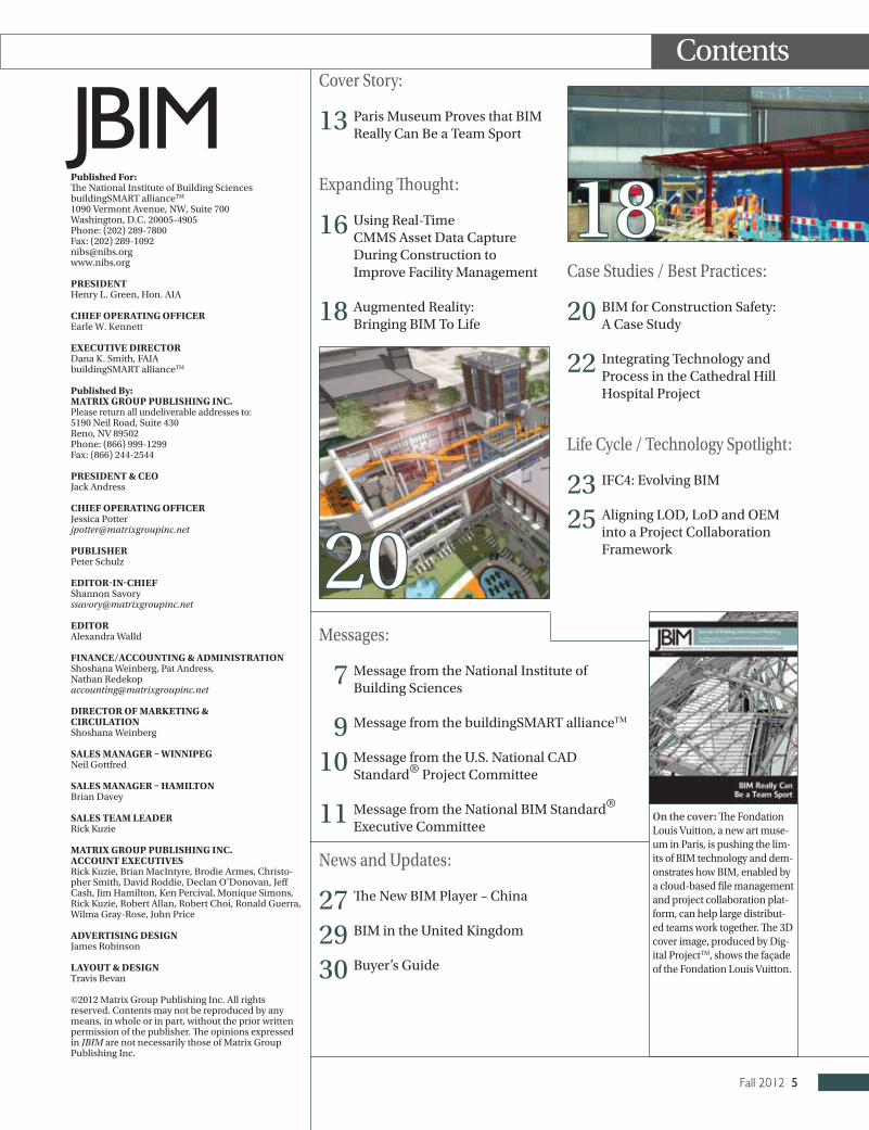
13 Paris Museum Proves that BIM Really Can Be a Team Sport
Expanding Thought:
16 Using Real-Time CMMS Asset Data Capture During Construction to Improve Facility Management
18 Augmented Reality: Bringing BIM To Life
Case Studies / Best Practices:
20 BIM for Construction Safety: A Case Study
22 Integrating Technology and Process in the Cathedral Hill Hospital Project
Life Cycle / Technology Spotlight:
23 IFC4: Evolving BIM
25 Aligning LOD, LoD and OEM into a Project Collaboration Framework
on the cover: The Fondation Louis Vuitton, a new art muse-um in Paris, is pushing the lim-its of BIM technology and dem-onstrates how BIM, enabled by a cloud-based file management and project collaboration plat-form, can help large distribut-ed teams work together. The 3D cover image, produced by Dig-ital ProjectTM, shows the façade of the Fondation Louis Vuitton.
Messages:
7 Message from the National Institute of Building Sciences
9 Message from the buildingSMART allianceTM
10 Message from the U.S. National CAD Standard® Project Committee
11 Message from the National BIM Standard® Executive Committee
News and Updates:
27 The New BIM Player – China
29 BIM in the United Kingdom
30 Buyer’s Guide
18
20

Fall 2012 7
Message from the National Institute of Building Sciences
Henry L. Green, Hon. AIA
2012 HAS BEEN A GOOD yEAR FOR building information modeling (BIM), full of significant progress. One par-ticular milestone is the release of the National BIM Standard-United StatesTM (NBIMS-USTM), Version 2. I would like to personally thank David Morris, chair of the NBIMS-USTM, Version 2 Project Com-mittee, for his leadership developing the standard over the past several years. Dave, who is director of virtual construction at EMCOR Group Inc., has worked tirelessly to move this effort forward.
NBIMS-USTM, Version 2 is a good met-ric of where we realistically stand with BIM now. yet, there is more to do be-fore we achieve our BIM vision. When it first came in to being, some people de-scribed BIM as, “CAD on steroids.” How-ever, BIM is much more than 3D drafting. When practiced correctly, BIM is meant to support collaboration across the facilities life cycle. BIM is the flow of information through a project, from inception to com-pletion and throughout the entire life cy-cle of a structure.
yes, NBIMS-USTM, Version 2 is a good metric because it documents the level of consistent interoperability that exists in the facilities industry. It is not enough, however, just to show that two software packages can exchange information. Members of the construction industry themselves need to be able to accept the transfer of data from different parties and know that information comes from a test-ed and reliable source. Using a consensus process that includes a broad array of us-ers, developers and innovators is critical
to the development of standards that the industry can place trust in.
This fall, the National Institute of Build-ing Sciences buildingSMART allianceTM is embarking on the next edition of the standard: NBIMS-USTM, Version 3. The Version 3 Project Committee will be under the leadership of Chris Moor, who is di-rector of industry initiatives at the Ameri-can Institute of Steel Construction (AISC), which has demonstrated a significant commitment to the development of BIM and the focus of the Alliance. The AISC BIM Committee made a major decision in changing the way they do business, de-ciding to move from their very successful CIMSteel Integration Standards (CIS/2)—the product model for exchanging data about structural steel project informa-tion—to an Industry Foundation Classes (IFC)-based approach to interoperabili-ty because they believe that this is the way of the future. Steel is far more advanced than many other aspects of our indus-try, largely because they have had a wide-ly used standard for some time. Hence, I believe them to be a good role model for others to emulate. Chris brings consider-able knowledge and understanding to this leadership role. It will be invaluable as we move the development of NBIMS-USTM, Version 3 forward.
BIM is also moving forward, gain-ing traction worldwide. Most notably of late is in the United Kingdom. BIM was used in the development of the Olympic compound for the 2012 Summer Games. Perhaps that experience demonstrat-ed to the British Government the val-ue and efficiencies that can be gained through the use of BIM…as that govern-ment has made a major commitment to move to open standards-based BIM by 2016, using our Construction Oper-ations Building information exchange (COBie). COBie, which was developed at the U.S. Army Corps of Engineers Engi-neer Research and Development Center
in Champlain, Illinois, is included in the NBIMS-USTM, Version 2. COBie allows information about a facility to remain actionable as it moves from one phase of a project to the next. COBie demon-strates well the importance of the “I” in BIM. I think this effort by the United Kingdom will be a great way to demon-strate to the world how implementing BIM can benefit their building projects.
The “I” in BIM is extremely important. It’s where you come in. Without your in-formation, without your involvement, without your interest, without your use and implementation of BIM, the indus-try is not going to achieve the BIM vision. your participation can further the devel-opment of NBIMS-USTM because you can identify ways to collaborate and to ensure the necessary approaches are included in the next edition.
Get involved in the NBIMS-USTM, Ver-sion 3 development. The Planning and Project Committees will both be meet-ing during Building Innovation 2013—the National Institute of Building Sciences Annual Conference and Expo, to be held January 7-10 in Washington, D.C. The conference also will have edu-cational sessions, information exchang-es and a number of other related activities to further expand your BIM knowledge. If you have not yet made plans to attend this event, I hope you will add it to your calendar.
If you’re not a member of the NBIMS-USTM, Version 3 Project Committee, sign up while you’re thinking of it. If you’re not an Institute member, take the opportunity to become one when you register for the conference.
yes, 2012 has been a good year for BIM but I think it is only going to get better in 2013.
I look forward to seeing you in January.
Henry L. Green, Hon. AIAPresident
The “I” in BIM is extremely important. It’s where you come in. Without your information, without your involvement, without your interest, without your use
and implementation of BIM, the industry is not going to achieve the BIM vision.


Fall 2012 9
Message from the buildingSMART allianceTM
OVER THE PAST SEVERAL MONTHS, THE buildingSMART alliance™ (bSa) has been try-ing to get the message out that building in-formation modeling (BIM) is a team sport. It seems that while the industry is improv-ing capabilities in individual areas of exper-tise, there is still little interest in seeing how information that has been created by others can be used and shared. The chief argument made is “I am responsible for the informa-tion so I must gather it in order to have con-fidence in it.” However, in life there is a lot of information that is created by others, yet still relied on every day. For example, is there any car owner that verifies the engineering calculations?
People are also concerned about oth-ers taking their data and calling it their own. Again, if the Ford name is on the car, no one claims it as their own design. Granted,
information is a little harder to track. Howev-er, the information technology world solved this problem years ago with information as-surance and metadata, which is data about data. In other words, if you create an object or add information to it, then that fact needs to be carried with that object for the rest of its existence.
Adding and protecting metadata is a fundamental step that the industry must take in order to achieve interoperability. The Building Information Modeling Serv-er information exchange (BIMSie) pro-ject is looking at how to deliver information this way. More information is available at www.buildingsmartalliance.org. Click on Projects and then choose Active Projects. If adopted as a standard, this will be break-through technology in support of sharing.
Several articles in this issue of the Jour-nal of Building Information Modeling (JBIM) point to information flowing from one phase of a project to another. yet, this critical aspect has not yet taken root. Unfortunately, the in-dustry is still developing separate models that are not communicating. The impact that data flow will have is illustrated by the Con-struction Operations Building information exchange (COBie) and that is why it is such an important product. COBie accomplishes several things. First, it keeps information in a usable form. Second, it demonstrates how information can flow. Third, it is usable by just about anyone. yet for all the information potential, it is still lacking in its ability to link tightly to 3D objects. Personally, I am confi-dent that will come soon.
Just to give fair warning to United States design and construction companies, things are starting to heat up overseas. There will be more companies like Skanska winning projects here at home as companies like them are realizing the financial and opera-tional benefits of a commitment to doing all projects using Industry Foundation Class-es (IFC)-based BIM. BIM-related ideas that our industry has been working on for many years are being put into practice in the Unit-ed Kingdom, Norway, Finland, the Republic of Korea and China.
The world is paying very close atten-tion to the good work the bSa is doing and they’re using it to their full advantage. Time is of the essence to ensure that the United States implements and reaps the benefits of this knowledge too. I have recently received several presentations from Chinese groups on the implementation of BIM standards in China. They are proposing a National BIM Standard – CHN and so the bSa is begin-ning work to put a memorandum of under-standing (MOU) into place so that we can share the knowledge and still protect our in-tellectual capital. The United Kingdom is also implementing BIM from a mandate that comes from the highest levels of government. They are focusing on the implementation of COBie.
The Alliance is working with its MOU-holding associations (approximately 250 manufacturing groups and 150 profession-al associations) to ensure that business pro-cesses are starting to change. The bulk of
Dana K. Smith, FAIA
Continued on page 10
10 Journal of Building Information Modeling
AS I WRITE THIS, WE’RE IN THE PROCESS OF rebuilding the committees and leadership that will lead us through United States Na-tional CAD Standard® (NCS), Version 6. I was the chairman of the NCS Project Com-mittee for Version 5 and I have been asked to stay on as chair for this one too, which I will gladly do. By the time this issue of The Journal of Building Information Mod-eling (JBIM) is published, the teams will be in place and we will likely be in full swing, bugging you about getting involved with this or that.
In Version 5 we added standards for the current projects that you are working on. What is it going to be this time? As you participate in the process, the process is informed. This is an industry-directed ef-fort and the more industry involvement, the more relevant the result. I am a little bummed out because we have fewer peo-ple on our Project Committee than we have had in the past. People are using NCS but fewer people seem interested in joining the committee. We try to make it pretty pain-less. you are invited to do committee work and attend conference calls or face-to-face meetings, but none of that is required.
What is required is that you vote, every time, pretty simple. Sign up at www.build-ingsmartalliance.org.
NCS and the National BIM Standard-United StatesTM (NBIMS-USTM) are both products of the National Institute of Build-ing Sciences and they both share resources. Both standards are primarily volunteer ef-forts and some of the volunteers that work on one also work on the other. Up until this point, the scheduling has worked out so that one or the other was going on. This time, for the first time, NCS, Version 6 will be happening at the same time as NBIMS, Version 3. Not exactly, of course, but there will be significant overlap. I anticipate that will bring an interesting dynamic to both standards.
I am one of the people involved with both efforts and have tried to come to grips with where these efforts might lead us. Is there a need to keep the NCS and NBIMS-USTM efforts separate? Is there some type of convergence in our future? What might that look like?
Consider the NCS. Perhaps some of the most useful stuff in there is the detail around how to use these electronic tools to represent the built environment in the same clear and concise way, making the inevitable and beneficial movement of the files from person to person, firm to firm and even phase to phase that much easier. Why would we treat the additional information related to building information modeling (BIM) as a reason to pull out a different standard? It is the same people, the same projects, sometimes even the same tools being used to produce this work. Perhaps a more holistic approach is at least worth a look. Will there be a time when there is a part of the standard that contains the de-tails around creating drawings and mod-els and whatnot? There is another part that
contains the information about all the oth-er good standards that are referenced from industry associations, academia and oth-er standards bodies. Some make the case that these things really are the standard, that the grey area is how to handle the best practices.
Maybe the best practices of how the tools are used in the architecture, engineer-ing, construction, operations and owner (AECOO) industry, in the projects that you are working on, needs a facelift. Maybe there is a better way to handle that part of these standards. With all of the social media tools available, maybe we need something more dynamic in the best practices area?
The overlap in schedule then may be more opportunity than burden. With the schedules of NCS and NBIMS-USTM over-lapping, this may be a great opportunity for both Project Committees to take a broad look and envision the path that makes the most sense for the AECOO industry in the United States.
The beginning of the process is always exciting. Where will the ballot items sub-mitted by our Project Committee take us? People have expressed interest in digging into Civil a little deeper and perhaps han-dling Reference Standards a little more like NBIMS-USTM. In what ways will these versions help us to move the industry for-ward? Are you interested in participating in the process? We would love to have you join in. you took the first step by picking up this publication and reading it. Go ahead and take the next step. I’d love to hear what you are thinking!
R. Mark ButlerChair, United States National CAD Standard®
Project CommitteeHDR ONE COMPANy | Many Solutions
Message from the U.S. National CAD Standard® Project Committee
R. Mark Butler
the work being done by these organizations focuses on the aspects of the industry that support their membership, yet, they are all working towards development and under-standing. They are the experts and should be the ones coordinating the efforts. The bSa is working to spread the work to these groups as much as possible.
The creation of a data dictionary coordi-nating tool is part of this effort. The indus-try absolutely must be able to understand the words being used. The industry does not necessarily all have to use the same words but they all must be understood. Currently, if one user puts “CMU” into a model, and an-other user is looking for “Concrete Block” in that same model, “CMU” will not come up.
Sadly, the industry has been talking about this problem for over 20 years yet there has been little progress. Hopefully it can be taken more seriously. I think the buildingSMART Data Dictionary will provide the infrastruc-ture for this to occur.
Dana (Deke) K. Smith, FAIAExecutive Director
Continued from page 9

Fall 2012 11
ACCEPTING THE ROLE OF NATIoNAL BIM Standard-United StatesTM (NBIMS-USTM) chair for Version 3 is exciting. It’s also somewhat daunting. Having served on the Project Committee during the develop-ment of Version 2, I am only too aware of the size of the task at hand, and at the same time, acutely sensitive to the importance of this work.
About a year ago, I was asked to pro-vide a testimonial as to the value of the buildingSMART allianceTM (bSa) and NBIMS-USTM. This is an excerpt of what I sent in: “Technology and building infor-mation modeling (BIM) continue to gain traction and evolve at breakneck speeds. Only when we look back in 20 years, will we understand just how monumen-tal the changes were and just how much the construction industry fundamentally changed. bSa recognizes this fact already and NBIMS-USTM is the tool to help us all get there unharmed.”
I went on to state that involvement “is an investment in the future of the construc-tion industry.” This is why I accept the chal-lenge ahead.
Every step we take with NBIMS-USTM needs to be a big one, moving the indus-try forward at the right pace and with bal-anced content. To make this happen, we need a large team of dedicated and high-ly knowledgeable individuals. Fortunately, history has shown us we have those indi-viduals on the Project Committee.
NBIMS-USTM GoalSWhile browsing through the bSa web-
site, another testimonial caught my eye. It really gets to the heart of what we are
aiming to achieve. Steve Holzer of eM8S wrote: “One of our greatest challenges is how to succinctly communicate what each stakeholder is to provide or accomplish. Often each stakeholder has their own lan-guage, when what we need to do is stand-ardize common terms and best practices we all can use.”
This is a pointedly accurate descrip-tion of one of the standard’s core objectives and while we need to take gradual steps to achieve it, these two sentences could be the most precise description we have about what NBIMS-USTM will become.
Here is what I know:• NBIMS-USTM is about building some-
thing people can use as a practical guide to help them investigate, adopt, evolve and execute their BIM practices and processes.
• NBIMS-USTM is a guide and also a tool for software vendors. Vendors should be able to utilize NBIMS-USTM as a way of ensuring they are developing the tools the industry needs, in the way they need them.
• NBIMS-USTM needs to be accessible. It needs to be easy to find, read and adopt. We need to remove the confusion sur-rounding BIM and make it accessible for everyone, for every project. We may not get there in Version 3, or even 4 or 5, but that has to be the goal.
• NBIMS-USTM needs to help overcome obstacles—real or perceived—to adopt-ing BIM.
• Our industry needs to know why NBIMS-USTM exists, what it’s for, why it’s relevant, who uses it, why do they use it and what value it brings.
• Lastly, the industry needs to know that this is an open organization that can be engaged with. Everyone can have a voice and be involved in the develop-ment of the standard. This is not a cabal.As James Vandezande, a principal at
HOK, summed up in his testimonial: “The Alliance connects us with pioneers who will drive improved efficiency and produc-tivity in design and construction processes.
Getting involved in the development of open BIM standards allows architects and engineers to help shape process improve-ments and interoperability.”
NBIMS-USTM, VeRSIoN 3Version 2 is available in two versions
online and has been downloaded by thou-sands of people around the world. Version 3 efforts will be well underway by the time you are reading this and we already have considerable interest for potential ballots.
As a reminder, NBIMS-USTM is made up of three essential elements:1. Core Standards: Highly technical soft-
ware standards primarily focused on interoperability.
2. Reference Standards: Existing stand-ards that play a considerable role in developing BIM processes. These are developed by allied standards organiza-tions and have been already adopted by the industry.
3. Social Exchange Standards/Prac-tice Documents: Proven processes or ways of working when using BIM. These may not be absolute “standards” in the true sense of the word but represent guidelines, best practices and reliable methods of working for organizations wishing to adopt BIM. The last area represents a major chal-
lenge—and major growth area. It’s consid-erably under-represented and needs the pioneers and innovators in the industry to step up and help with its evolution. Any-one can submit a ballot for consideration and ballot authors can get assistance just by asking. Every idea and submission will be fairly evaluated.
NBIMS-USTM, Version 3 will be anoth-er major leap forward toward forming the foundation for the way the construction in-dustry uses BIM. I am looking forward to that challenge.
Chris MoorChair, National BIM Standard-United StatesTM
Project Committee
Message from the National BIM Standard-United StatesTM Executive Committee
Chris Moor
NBIMS-USTM is about building something people can use as a practical guide to help them investigate, adopt, evolve and execute their BIM
practices and processes.

Fall 2012 13
Cover Story
FOR MANy yEARS, BUILDING INFORMATION modeling (BIM) has been lauded as the an-tidote for inefficiencies that pervade the ar-chitecture, engineering and construction (AEC) industries and, now, the use of digi-tal building models has become a standard part of the building process. But as projects become bigger and more distributed, some teams struggle with the collaborative as-pects inherent to BIM. Then again, some teams don’t.
This article describes how BIM and BIM technology are being used very effective-ly on a high-profile and extremely com-plex project, the Fondation Louis Vuitton, a new art museum in Paris designed by Gehry Partners. The building is a showpiece—not only of art, but also of design and technolo-gy. The project is pushing the limits of BIM technology and demonstrates how BIM, en-abled by a cloud-based file management and project collaboration platform, can help large distributed teams work together.
The project includes:• 15+ design teams from around the world;• More than 400 model users and
collaborators; • Nearly 100 gigabites of BIM-based mod-
el data; • Over 100,000 version reiterations of the
building model;• 19,000 unique CNC molded glass rein-
forced concrete panels; and
• 3,500 unique CNC molded curved glass panels.
PRojeCT BaCkGRoUNdThe Fondation Louis Vuitton is an icon-
ic new museum under construction, locat-ed in a massive park, the Bois du Boulogne. It will host a permanent art collection as well as rotating exhibitions, performances and lectures. The building itself will serve as a gateway to the Jardin d’Acclimatation, a popular zoological garden and children’s amusement park.
The structure has been likened to a sailboat with billowing glass sails (FIGURe 1). The use of glass as the primary exterior material plays a principal role in the architecture of the building, ensuring that it will complement the surrounding natural environment. The design includes a series of large curved-glass “sails” and dozens of fibrous concrete “iceberg” surfaces.
Key collaborators on the project team included Gehry Partners; the owner, Fon-dation Louis Vuitton; the façade engineer, RFR/TESS; executive architect, Studios Ar-chitecture; structural engineer, SETEC Bati-ment; mechanical engineer, IBE; the façade contractor, EIFFEL; and the general con-tractor, VINCI. The project’s BIM deliv-ery process was orchestrated and is being managed by Gehry Technologies (GT). The 3D project delivery system includes
Digital ProjectTM for all 3D design and the technology now resident in GT’s recent-ly-announced BIM collaboration platform, GTeamTM.
ChalleNGeThe unique shape and curved glass fa-
çade (FIGURe 2) of the structure neces-sitates very close teamwork amongst a spectrum of design disciplines and fabrica-tors, as well as the general contractor and the owner. Therefore, one of the primary challenges is the effective collaboration of this geographically-dispersed project team. The design architects are in Los Angeles, while most of the rest of the design team are in offices in Paris. Other team members are in the United Kingdom, Germany and Italy. In all, there are over 10 companies involved in the design process, all of whom require some level of access to current building in-formation. And many of the design teams need to define certain aspects of the geom-etry parametrically in the same model. As such, the project requires distributed, multi-user, simultaneous access to a single model.
In Paris, the key project participants—executive architect, structural engineer, façade engineer, mechanical systems en-gineer and GT—are all co-located in trail-ers on the construction site. This improves communication but still poses barriers to model integration. There is a wide range
Paris Museum Proves that BIM Really Can Be a Team SportBy Andrew J. Witt
Figure 1. A rendering of the Foundation Louis Vuitton art museum.

14 Journal of Building Information Modeling
of authoring tools being used on the pro-ject, including Digital Project, Tekla, Sketch-Up, AutoCAD, Bocad, SolidWorks, ANSyS, STRAUSS, NASTRAN, SOFiSTiK, 3DVIA composer and Solibri.
The generous use of glass on the curved façade poses another significant challenge. Normally, curved glass is formed with met-al molds. But that manufacturing technique would have been cost-prohibitive on this project, as each panel has a unique shape, requiring over 3,500 individual molds. In-stead, the building team is using CNC mold-ed curved glass panels. In addition, the “iceberg” surfaces are composed of 19,000 different CNC-molded glass-reinforced concrete panels. To keep costs in check, this abundance of uniquely shaped exterior panels requires mass customization.
SolUTIoNThe architect’s goal of lightness and
transparency for the structure is being real-ized through the close collaboration among the architect, engineers and fabricators. This process of continuous and concurrent design and engineering involves approxi-mately 15 firms and 400 individuals working together using BIM software and a cloud-based collaboration platform. By combining advanced parametric models with an online collaboration platform built specifically for BIM and AEC professionals, the Fondation Louis Vuitton project team can communi-cate, synchronize and share BIM data and files from anywhere in the world. Moreover, BIM facilitates a close partnership between the architect and the client—a critical com-ponent of this owner-led project.
A precise structure for the organization of the data allows distributed team mem-bers to collaborate in a structured way on a single project model. This core project mod-el is a Digital Project master model but the team members also use a range of other
software tools to create and consume mod-els in various file formats that suit their own specific workflows. With approximately 100 people creating 3D content and 400 peo-ple accessing it, the project team relies on the technology of GTeam’sTM open collabo-ration platform to bring all those disparate files into a common format. Thus, the team members can contribute parametric mod-el content regardless of their different lo-cations and the entire team can access that model information without the need for the native modeling software. The model is an essential tool for project coordination and the definitive arbiter of how the building is being built.
The 3D project delivery system has ver-sioned over 10,000 distinct archived itera-tions of a design model consisting of more than 5,000 core files and tens of thousands of auxiliary files. It has already facilitated the distributed calculation of over 100,000,000 design optimization iterations for material-specific and fabrication-specific paneliza-tions and details.
PRojeCT ModelThe centralized Digital Project para-
metric is stored on a central server and is automatically synced to individual team members’ computers. This allows users to work with the actual model files transpar-ently, while maintaining project control and accelerating the communication of project data. GTeamTM also manages the distribu-tion, versioning, access and security of the model.
The product model provides a natu-ral way to hierarchically organize work on the model. Since the project itself has a cer-tain organization chart, the chart can natu-rally be mapped onto the project structure to modularize the associated work. In ef-fect, the structure of the model becomes the work packaging plan for the design and
Figure 2. The design includes a unique shape and curved glass.

Fall 2012 15
construction of the project. This product structure has a natural mapping to a file or-ganization, which again mirrors the organi-zation of the project itself. Ultimately, it is at this file-system level that the hierarchical or-ganization is connected to GTeam’sTM ver-sioning tools, which store a master copy of the model in the cloud.
Another interesting aspect of the project is that very few of the collaborators (outside of Gehry Partners) had ever used a 3D de-sign process prior to this project. As a result of this inexperience, there was some under-standable skepticism around the 3D pro-cess and particularly about collaboration on the 3D model. The challenge of implement-ing an ambitious collaboration system was as much social and organizational as it was technical. To overcome the lack of 3D expe-rience on the project, GT implemented a se-ries of project-based continuous training classes on Digital Project and GTeamTM for project participants.
MaSS CUSToMIzaTIoNGenerative methods are most common-
ly used for design explorations, where im-plicit geometry or a very few rules of thumb suffice for validating design feasibility. However, the mechanical processes of fab-rication often have decisive impacts on the design geometry itself, particularly at the detail level. Validation on this level often re-quires the analysis of dozens of parameters for each assembly piece, even for apparent-ly simple systems. To this end, the project team has developed hundreds of self-adapt-ing 3D details. These intelligent components enable the design team to create thousands of categorized variants throughout the pro-ject in a generative and consistent manner, using rules to, for example, optimize pan-el sizes and control joint distances between them.
Since these modules, like the rest of the model, are stored on a model server, the engineers can modify their details with full technical knowledge while other team members can still validate the pure spatial aspects of the designed details. After the de-sign of the initial prototype, the generation of these details is distributed to all the team members’ machines by the model server.
The centralization and redistribution of the model also facilitated a new scale of de-sign computation and optimization, which ultimately was necessary to address some of
the complex geometric issues of the project. Since many analyses and generative exercis-es for the building were computation-inten-sive and time-consuming, an early initiative of GT was to facilitate the off-loading of this processing to other low-demand machines, essentially creating a private cloud for gen-erative geometry and optimization. This ca-pacity was leveraged to generatively model and detail the most complex parts of the building.
CoMPleTING The FaBRICaTIoN ChaIN
The use of intelligent components kept complexity, cost and quality under control throughout the design process. Now, com-puter-controlled fabrication processes are having a similar effect during construc-tion. Fabricators rely on the master building model to automatically produce individu-al shop drawings. Every extrusion is being custom CNC cut and made to order direct-ly from the master building model.
The model also represents the sole source for managing and validating change—from design to fabrication and installa-tion. By linking the construction schedule to the master model, the general contrac-tor is using 4D modeling for its construc-tion planning, which helps optimize onsite resources and construction sequencing. In addition, fabricated panel components are laser scanned and virtually positioned in the model to confirm correct tolerances
and configurations ahead of shipping and installation.
The project consultants and subcontrac-tors also integrate engineering intelligence into the model, which the owner can use for operations and maintenance. This includes information such as warranty details and anticipated replacement dates for routine maintenance planning.
SUMMaRyFondation Louis Vuitton is on schedule
for opening in 2013. The project exempli-fies how BIM can enable design, fabrication and construction excellence. In recogni-tion, Fondation Louis Vuitton was selected as the 2012 recipient of the prestigious BIM Excellence Award, given by the Ameri-can Institute of Architects (AIA) Technol-ogy in Architectural Practice Knowledge Community.
The project draws from building exper-tise around the world. BIM software and cloud-based collaboration enabled concur-rent design, advanced parametrics brought the project to the next level and an auto-mated CNC process is completing the fab-rication chain. BIM has increased clarity and project understanding throughout the project team and supply chain, resulting in faster cycle times and more automated higher-quality fabrication processes. n
Andrew Witt is Director of Research at Gehry Technologies, Inc.
16 Journal of Building Information Modeling
Expanding Thought
WE ARE MOVING TO A MOBILE-CENTRIC world, where information can be at our finger tips not just in minutes but in sec-onds. Mobile applications are becoming commonplace in every industry sector. They are used by commerce to monitor transportation and overnight delivery sys-tems to track packages, all by real-time data capture. Could it be that real-time data collection has value for facility man-agement (FM)?
This article explores the value proposi-tion of using mobile applications to cap-ture real-time asset data for improving FM activities. Currently, new asset infor-mation is delivered to the FM group af-ter construction as a “handover”. What asset data is received is manually loaded into the owner’s computerized mainte-nance management systems (CMMS) af-ter handover or, in some cases, is never loaded at all.
The combination of delayed entry and lack of equipment data in CMMS data-bases has a significant impact on the FM group’s ability to effectively maintain equipment and achieve intended ser-vice life. Because the maintenance per-sonnel depend heavily on the CMMS to receive service orders, search for equip-ment information, reserve inventory and prepare work plans, it’s critical to have correct and complete equipment data. But it’s the timeliness of data entry that primarily impacts FM activities, such as preventative maintenance (PM) planning and scheduling, identifying required op-erations training and determining spare part availability. The reality is, these activ-ities are not initiated until after the “hand- over”, when the building has begun oper-ating, meaning FM is already behind on maintenance.
On the other hand, consider a transi-tion to operations (ToS) approach, which will create a more seamless handover by utilizing mobile devices for real-time
updates of CMMS databases. At the start of a project, basic asset data from a build-ing information model (BIM) is uploaded into the CMMS. Then, as the equipment is set, mobile applications capture the asset-specific data directly into the CMMS. This workflow allows time for the FM person-nel to set up equipment PM plans, ensure critical spare parts are identified, and al-lows time to determine what equipment training is required before the building be-gins operations.
In most facilities today, once a piece of equipment is identified as requiring operations and maintenance (O&M), it triggers a sequence of FM activities, be-ginning with the creation of a new asset in the CMMS. For this task, the FM group will need basic information on the equip-ment, such as classification type, and manufacturer and vendor data. The man-ufacturer name, along with the model number, helps the FM team obtain O&M manuals and performance data, while the serial number is used for warranty issues and replacement parts orders. To locate equipment for servicing or emer-gency repairs, the FM team will require the building, floor and room numbers as well as what quadrant of the room the equipment resides. For warranty infor-mation, the team needs the installation date, which often becomes the default start of the warranty period, and the ven-dor contact information, in cases where a service call arises.
Once this information is gathered, the equipment data is manually entered into the CMMS and assigned an asset num-ber, which identifies its existence. The next task is to create an equipment-spe-cific job plan and schedule to ensure proper maintenance is performed per the manufacturer’s recommendations. The follow-on activities include identi-fying spare parts and inventory require-ments and determining any special tools or training needed to properly perform O&M functions.
One activity vital to operations, but rarely considered, is obtaining the in-stalled equipment’s operating parameters. The final commissioning report provides design operating ranges and set point ver-ification but not likely the equipment’s ac-tual operating range. Although delivered to the design engineers or project manag-er to document that the building systems met the design basis, this report almost never makes it to the FM group.
The ramifications of beginning facili-ty maintenance after handover are fairly significant but commonly ignored. Wait-ing to receive the equipment information before beginning to enter new assets cre-ates poor equipment maintenance (no PMs performed) and causes unexpected spikes in resource loading and PM back-log (because there is no upfront sched-uling). It also results in a lack of proper training (so it takes longer to perform PM) and insufficient spare parts on-hand (in-creasing the time of PM). This inefficiency also results in wasted time due to start-stop work and disruptions other than pre-scheduled PMs. This creates a perception that FM is not staying up with maintain-ing the facility.
What if, by using mobile applications and devices, FM personnel could capture the required equipment nameplate data and upload it in real-time to their CMMS databases during construction?
Using Real-Time CMMS Asset Data Capture During Construction to Improve Facility Management By Birgitta Foster
By taking a more proactive approach, like making a transition
over time to operations (instead of a single moment in time like
handover implies), there should be improvements not only in FM
perception and O&M performance metrics but, more importantly, in extending equipment service life.

Fall 2012 17
Wait, isn’t that the contractor’s job? yes, but how well has that worked? If the contractor, whose sole responsibil-ity is to install the equipment per de-sign, is expected to properly collect equipment data and ensure its accu-racy and completeness, then why does the FM team always seem to re-collect the equipment data after the building is handed over?
On a new building, it’s not uncommon to have over 500 new assets to enter into the CMMS system. The time it would take to properly complete the six FM activities (entering CMMS data and documents, creating PM job plans and schedules, identifying spare parts, determining O&M training requirements, establishing war-ranty periods and obtaining equipment operational ranges) could be up to three man-hours per new asset. For a new building, that is 1,500 man-hours or one full-time employee for over eight months! And that is after handover and the equip-ment is already in operation. It is clear that the FM needs the information early because even if FM began receiving com-plete asset data at handoff, it still does not address the delay in planning and sched-uling PMs, prompting the call for alterna-tive workflows.
Through individual interviews with O&M personnel, it has become apparent that their ability to properly maintain the facility assets is significantly impacted by the timing of the current project hand-over process. However, through the lev-eraging of new technology, like BIM and mobile applications, that can be changed. By taking a more proactive approach, like making a transition over time to opera-tions (instead of a single moment in time like handover implies), there should be improvements not only in FM perception and O&M performance metrics but, more importantly, in extending equipment ser-vice life.
Handover nirvana? Maybe. By adopt-ing a transition to operations approach with real-time CMMS asset data capture, not only does FM improve, it makes facil-ity managers a part of the project “team” and not just the ones who come in after the dust clears. n
Birgitta Foster is Assisting Director for the buildingSMART alliance™.
18 Journal of Building Information Modeling
Expanding Thought
RealITySince the term was first coined in 1990
at Boeing1, augmented reality (AR) had remained a research or mostly military application. Over the last 10 years, though, the automotive industry has become a leader in the development of AR for factory planning exercises2, with more powerful laptops that allow users to view changes live in the context of their immediate surroundings. It is only in the last few years, however, with the explosion of the use of mobile devices and a similar growth in information-rich building information modeling (BIM), that AR has reached the construction site. AR permits viewing the design, construction or operational information where it’s needed: on location.
AR differs from virtual reality in that it enhances rather than replaces the real world. What is augmented on a construction project? Mostly the visual environment—seeing the future (what is not yet built), seeing what’s hidden (buried) and seeing what cannot be seen
(alignments, kinematic envelopes). Also, additional data associated with the assets can be accessed where it is linked to the graphic elements.
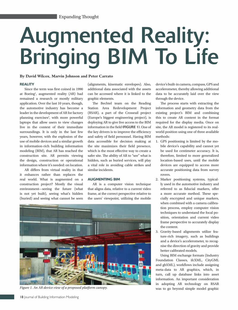
The Bechtel team on the Reading Station Area Redevelopment Project (RSAR), a part of the Crossrail project (Europe’s biggest engineering project), is deploying AR to give live access to the BIM information in the field (FIGURe 1). One of the key drivers is to improve the efficiency and safety of field personnel. Having BIM data accessible for decision making at the site maximizes their field presence, which is the most effective way to create a safer site. The ability of AR to “see” what is hidden, such as buried services, will play a vital role in avoiding cable strikes and similar incidents.
aUGMeNTING BIMAR is a computer vision technique
that aligns data, relative to a current video frame, at the correct perspective relative to the users’ viewpoint, utilizing the mobile
device’s built-in camera, compass, GPS and accelerometer, thereby allowing additional data to be accurately laid over the view through the device.
The process starts with extracting the information and geometry data from the existing project’s BIM and combining this to create AR content in the format required for the display media. Once on site, the AR model is registered to its real-world position using one of three available methods:1. GPS positioning is limited by the mo-
bile device’s capability and cannot yet be used for centimeter accuracy. It is, therefore, limited to more generalized location-based uses, until the mobile devices are equipped to access more accurate positioning data from survey rovers.
2. Marker positioning systems, typical-ly used in the automotive industry and referred to as fiducial markers, offer a more accurate method. These spe-cially encrypted and unique markers, when combined with a camera calibra-tion process, employ computer vision techniques to understand the focal po-sition, orientation and current video frame perspective to accurately display the content.
3. Gravity-based alignments utilize fea-ture-rich imagery, such as buildings and a device’s accelerometer, to recog-nise the direction of gravity and provide better calibrated models.Using BIM exchange formats (Industry
Foundation Classes, ifcXML, CityGML and gbXML), workflows include assigning meta-data to AR graphics, which, in turn, call up database links into asset information. An important consideration in adopting AR technology on RSAR was to go beyond simple model graphic
Augmented Reality: Bringing BIM To LifeBy David Wilcox, Marvin Johnson and Peter Carrato
Figure 1. An AR device view of a proposed platform canopy.
Fall 2012 19
displays relative to a known position so that the technology would supplement the information the users have for their task. It was also decided that AR should extend the BIM process, in that data should not only be retrieved from the model but also allow for two-way transfer to record site data.
The new Augmented Reality Experience Language (AREL)-formatted AR systems are able to combine IFC standard (ISO16730) compliant building models into the process so that each asset is recognised within the AR media display device. When data is accessed from project cloud servers, site teams can retrieve and visualize potentially unlimited project data based on position.
aUGMeNTed RealITyOne of the RSAR requirements is to
provide site teams with 4D simulations of construction sequences at stage gate reviews. This has been a desktop exercise but now AR has achieved viewing of the 4D sequence in the field.
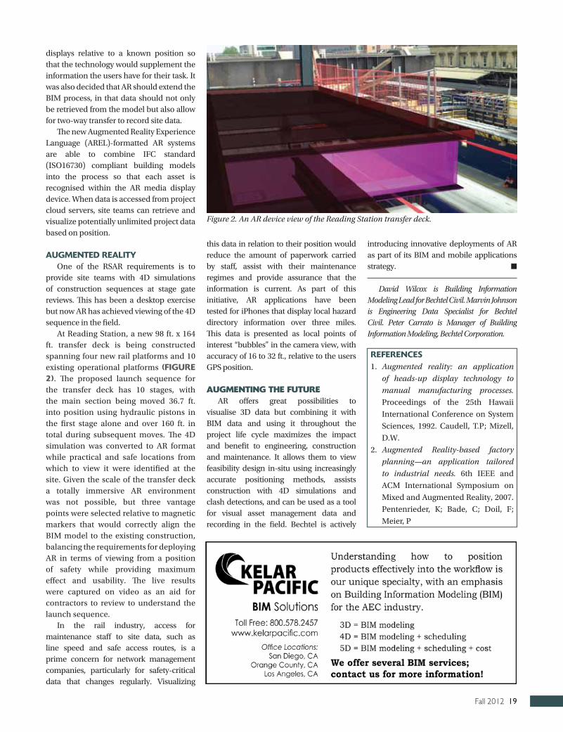
At Reading Station, a new 98 ft. x 164 ft. transfer deck is being constructed spanning four new rail platforms and 10 existing operational platforms (FIGURe 2). The proposed launch sequence for the transfer deck has 10 stages, with the main section being moved 36.7 ft. into position using hydraulic pistons in the first stage alone and over 160 ft. in total during subsequent moves. The 4D simulation was converted to AR format while practical and safe locations from which to view it were identified at the site. Given the scale of the transfer deck a totally immersive AR environment was not possible, but three vantage points were selected relative to magnetic markers that would correctly align the BIM model to the existing construction, balancing the requirements for deploying AR in terms of viewing from a position of safety while providing maximum effect and usability. The live results were captured on video as an aid for contractors to review to understand the launch sequence.
In the rail industry, access for maintenance staff to site data, such as line speed and safe access routes, is a prime concern for network management companies, particularly for safety-critical data that changes regularly. Visualizing
this data in relation to their position would reduce the amount of paperwork carried by staff, assist with their maintenance regimes and provide assurance that the information is current. As part of this initiative, AR applications have been tested for iPhones that display local hazard directory information over three miles. This data is presented as local points of interest “bubbles” in the camera view, with accuracy of 16 to 32 ft., relative to the users GPS position.
Augmenting the FutureAR offers great possibilities to
visualise 3D data but combining it with BIM data and using it throughout the project life cycle maximizes the impact and benefit to engineering, construction and maintenance. It allows them to view feasibility design in-situ using increasingly accurate positioning methods, assists construction with 4D simulations and clash detections, and can be used as a tool for visual asset management data and recording in the field. Bechtel is actively
introducing innovative deployments of AR as part of its BIM and mobile applications strategy. n
David Wilcox is Building Information Modeling Lead for Bechtel Civil. Marvin Johnson is Engineering Data Specialist for Bechtel Civil. Peter Carrato is Manager of Building Information Modeling, Bechtel Corporation.
ReFeReNCeS1. Augmented reality: an application
of heads-up display technology to
manual manufacturing processes.
Proceedings of the 25th Hawaii
International Conference on System
Sciences, 1992. Caudell, T.P; Mizell,
D.W.
2. Augmented Reality-based factory
planning—an application tailored
to industrial needs. 6th IEEE and
ACM International Symposium on
Mixed and Augmented Reality, 2007.
Pentenrieder, K; Bade, C; Doil, F;
Meier, P
Figure 2. An AR device view of the Reading Station transfer deck.

20 Journal of Building Information Modeling
Case Studies / Best Practices
A CRUCIAL FACTOR IN CONSTRUCTION SAFETy PLANNING is to properly identify all possible hazards before they occur. A build-ing information model (BIM) allows construction stakeholders to vis-ually assess jobsite conditions and recognize hazards, and it provides them sufficient time to develop adequate hazard mitigation plans.
The utilization of BIM technology can result in improved occu-pational safety by connecting the safety issues more closely to con-struction planning. This provides a more illustrative site layout, while providing methods for managing and visualizing up-to-date plans and site status information. The use of BIM also encourag-es other project partners, such as designers, sub-contractors and safety specialists, to become actively involved in both risk assess-ment and planning.
This article reports an in-progress research project where BIM technology is utilized to perform safety planning and manage-ment for an ongoing construction project located at the campus of the Auburn University, in Auburn, Alabama. The project is a Recre-ation & Wellness Center. BIM models and 4D simulations are used to communicate the following safety plans: 1) crane management; 2) fall protection; and 3) emergency response plans. 4D phasing simulations, 3D walk-throughs and 3D renderings are utilized to identify various hazards and to communicate safety management plans to the workers.
The architecture firm, 360 Architecture, based in Kansas City, Missouri, developed the base BIM model of this project for com-munication and visualization purposes. The research team ac-quired this model and enhanced it by adding missing design details and temporary safety features. FIGURe 1 is a project ren-dering used for marketing purposes.
The following sections describe the BIM-based safety plans generated from the base BIM model.
CRaNe MaNaGeMeNT PlaNThe purpose of a crane management plan is to: 1) identify the
swing radius of the crane to ensure its safe distance from power lines and nearby structures; and 2) identify what trade/crew will be utilizing the crane at a particular time. On this project, two lat-tice-boom crawling cranes are being utilized to pick and place the structural members. The crane on the North side of the project is a 110-ton Link-Belt 218 HyLAB unit and the crane on the South side is a 250-ton Manitowoc Model 999 unit. FIGURe 2 illustrates the steel truss placement in the crane management plan.
As depicted in this image, the colored masses (yellow, orange and blue) are used to demonstrate the crane’s swing radius and zone of influence. The yellow mass communicates the possible ex-tent of the crane’s swinging boom at any moment during a partic-ular day. Collision detections can be utilized to generate weekly reports of any non-steel installation activities scheduled to take place within the crane’s planned swing radius, according to the placement dictated by the overall project schedule. The resulting
BIM for Construction Safety: A Case StudyBy Alex Behringer and Salman Azhar
Figure 1. A 3D rendering of the project
360
Arc
hite
ctu
re
Figure 2. The crane work zone and steel truss placement in the crane management plan.
PRojeCT deTaIlSowner: Auburn University Facilities DivisionProject Manager (Construction Team): Robins & Mortonarchitect: 360 ArchitectureCost: $50,000,000Size: 240,000 sq. ft.Delivery System: CM AgencyStart Date: October 2011 Projected Substantial Completion Date: May 2013
Fall 2012 21
report can be used during a segment of the project’s periodic safe-ty meetings to mitigate unplanned risks due to the crane’s interac-tion with construction personnel. Alternately, 4D simulations can be utilized for safely planning construction activities.
Fall PRoTeCTIoN PlaNThe fall protection plan for leading edges is prepared accord-
ing to OSHA Subpart M: Fall protection standards. Two types of fall protection railings are modeled: 2x4 wooden railings on the second level (concrete structure) that are bolted to the concrete slab and 3/8” steel aircraft cable railings on the third and higher levels of the project (steel structure). Holes in the elevated slabs are covered by plywood coverings and roped in caution tape, as required by OSHA.
After modeling the fall protection railing components, the rail-ings are placed on the structural BIM model. While performing this process, the researchers were able to identify multiple falling risks through the 3D view that were not easily found within the 2D plan view. These conditions included stairwells and skylights that were not yet constructed, so fall protection railing was placed at these locations. The modeled railings are then segregated by zones and levels and the resulting railing sections were exported to Syn-chro® for developing 4D simulations. The 4D simulation provides complete details to the contractor as to the location and date that the railings are to be installed or removed. FIGURe 3 depicts a typical railing family and its placement in the BIM model.
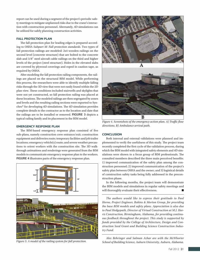
eMeRGeNCy ReSPoNSe PlaNThe BIM-based emergency response plan consisted of five
sub-plans, namely construction crew entrance/exit; construction equipment and deliveries route; temporary facilities and job trailer locations; emergency vehicle(s) route; and severe weather precau-tions to orient workers with the construction site. The 3D walk-through animations and renderings were generated from the BIM models to communicate emergency response plan to the workers. FIGURe 4 illustrates parts of the emergency response plan.
CoNClUSIoNBoth internal and external validations were planned and im-
plemented to verify the usefulness of this study. The project team recently completed the first cycle of the validation process, during which the BIM model with integrated safety elements and 4D sim-ulations were shown to a focus group of BIM professionals. The consulted members described the three main perceived benefits: 1) improved communication of the safety plan among the con-struction personnel; 2) improved communication of the project’s safety plan between OSHA and the owner; and 3) logistical details of construction safety tasks being fully addressed in the precon-struction phase.
In the following months, the project team will demonstrate the BIM models and simulations in regular safety meetings and will thoroughly evaluate their effectiveness. n
The authors would like to express their gratitude to Paul Horne, Project Engineer, Robins & Morton Group, for providing the base BIM models and safety plans. Appreciation is also due to Paul Hedgepath, Director of Virtual Construction at M.J. Har-ris Construction, Birmingham, Alabama, for providing continu-ous feedback throughout the project. This study is supported by funds provided by the College of Architecture, Design and Con-struction Seed Grant and Building Science Construction Indus-try Fund.
Alex Behringer and Salman Azhar are with the McWhorter School of Building Science, Auburn University, Auburn, Alabama.Figure 3. A model of the railing system for fall protection.
Figure 4. Screenshots of the emergency action plan. A) Traffic flow directions. B) Ambulance arrival path.
22 Journal of Building Information Modeling
Case Studies / Best Practices
AS BUILDING INFORMATION MODELING (BIM) SPREADS IN THE architecture, engineering and construction (AEC) industry, de-signers, engineers, contractors and owners are exploring how to best utilize it to improve the way they do business. This funda-mental change is further accelerated with the emergence of col-laborative project delivery methods such as integrated project delivery and lean construction. In this “perfect storm,” how do teams integrate, process and utilize BIM to its best extent?
Sutter Health’s Cathedral Hill Hospital (CHH) project is a 1.2 million square foot urban replacement hospital in San Francis-co, California. It is not just designed to be a state-of-the-art hos-pital but also to break new ground in multiple areas of design, construction and operations. As the CHH integrated project de-livery team (IPDT) nears completion of the preconstruction ef-forts, this paper aims to outline some of the key ideas and tools practiced in this phase.
adaPT BIM To FIT a CollaBoRaTIVe delIVeRy PRoCeSS
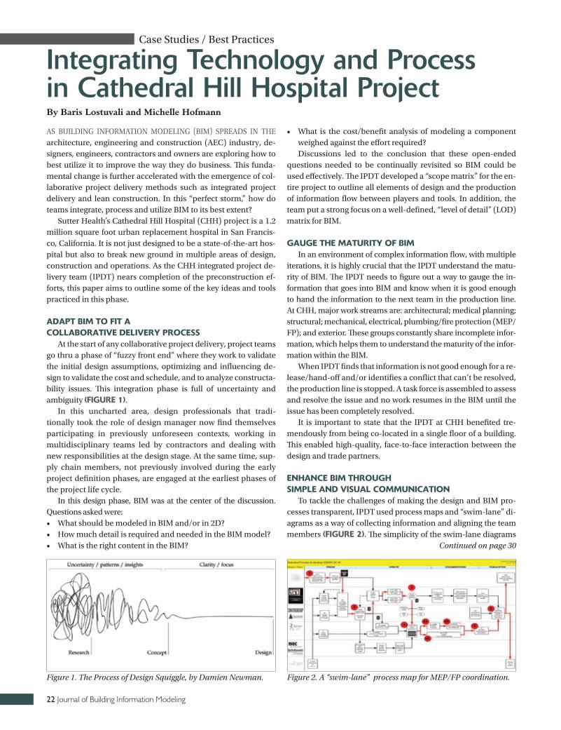
At the start of any collaborative project delivery, project teams go thru a phase of “fuzzy front end” where they work to validate the initial design assumptions, optimizing and influencing de-sign to validate the cost and schedule, and to analyze constructa-bility issues. This integration phase is full of uncertainty and ambiguity (FIGURe 1).
In this uncharted area, design professionals that tradi-tionally took the role of design manager now find themselves participating in previously unforeseen contexts, working in multidisciplinary teams led by contractors and dealing with new responsibilities at the design stage. At the same time, sup-ply chain members, not previously involved during the early project definition phases, are engaged at the earliest phases of the project life cycle.
In this design phase, BIM was at the center of the discussion. Questions asked were:• What should be modeled in BIM and/or in 2D? • How much detail is required and needed in the BIM model? • What is the right content in the BIM?
• What is the cost/benefit analysis of modeling a component weighed against the effort required? Discussions led to the conclusion that these open-ended
questions needed to be continually revisited so BIM could be used effectively. The IPDT developed a “scope matrix” for the en-tire project to outline all elements of design and the production of information flow between players and tools. In addition, the team put a strong focus on a well-defined, “level of detail” (LOD) matrix for BIM.
GaUGe The MaTURITy oF BIMIn an environment of complex information flow, with multiple
iterations, it is highly crucial that the IPDT understand the matu-rity of BIM. The IPDT needs to figure out a way to gauge the in-formation that goes into BIM and know when it is good enough to hand the information to the next team in the production line. At CHH, major work streams are: architectural; medical planning; structural; mechanical, electrical, plumbing/fire protection (MEP/FP); and exterior. These groups constantly share incomplete infor-mation, which helps them to understand the maturity of the infor-mation within the BIM.
When IPDT finds that information is not good enough for a re-lease/hand-off and/or identifies a conflict that can’t be resolved, the production line is stopped. A task force is assembled to assess and resolve the issue and no work resumes in the BIM until the issue has been completely resolved.
It is important to state that the IPDT at CHH benefited tre-mendously from being co-located in a single floor of a building. This enabled high-quality, face-to-face interaction between the design and trade partners.
eNhaNCe BIM ThRoUGh SIMPle aNd VISUal CoMMUNICaTIoN
To tackle the challenges of making the design and BIM pro-cesses transparent, IPDT used process maps and “swim-lane” di-agrams as a way of collecting information and aligning the team members (FIGURe 2). The simplicity of the swim-lane diagrams
Integrating Technology and Process in Cathedral Hill Hospital Project
Figure 2. A “swim-lane” process map for MEP/FP coordination.Figure 1. The Process of Design Squiggle, by Damien Newman.
By Baris Lostuvali and Michelle Hofmann
Continued on page 30
Fall 2012 23
Life Cycle / Technology Spotlight
IN RECENT yEARS, THE INDUSTRy Foundation Classes (IFC) standard for build-ing information modeling (BIM) has seen widespread adoption, supported by approx-imately 150 registered software applications. This article describes the next evolution of this standard, IFC4, and related efforts for achieving wider and deeper interoperability across software applications.
The goal of IFC has always been to de-scribe how building information can be lev-eraged across applications within and across vertical industries, supporting the vast ar-ray of disciplines encountered in the build-ing industry. To be useful across such a large ecosystem, such standards must capture necessary detail to describe how a building is to be built, along with the many non-physical aspects describing who is doing what, when, how and why. Meanwhile, many down-stream applications are only concerned with subsets of this information. Another aspect to address is the format of information, which must accommodate changing technology and diverse platforms, such as phones, tab-lets, desktops and servers. For basic appli-cations, XML provides ease of integration; compact formats such as STEP Physical For-mat (SPF) are more practical for represent-ing buildings in detail; spreadsheets such as Excel provide access to a wide range of us-ers without custom software; and databases of various forms may support collaboration among concurrent users.
Meanwhile, as more applications adopt IFC, customers have asked for deeper inte-gration to capture more detailed information across applications in a consistent way. To support this growing usage, IFC has evolved with initiatives on multiple fronts.
Data model: A number of enhancements have been introduced in IFC4, with a focus on system-wide improvements while main-taining backward compatibility.
Parametric design: While buildings are ultimately made of discrete components, during the design process it is often desirable
to use higher-level representations reflect-ing the design intent, so that changes can be made in one place, where the composi-tion and layout of components, can be au-tomatically updated to reflect the change. IFC4 introduces the concept of material pro-files, where axis-based components, such as beams, pipes and ducts, can be described by paths and cross-sections of materials, along with offsets relative to the axis and end points. Similarly, a concept of material con-stituents has been introduced where compo-nents, such as doors and windows, can have various parts (for example, framing and glaz-ing) defined by geometric aspects and cor-responding materials. Material layers allow flat components, such as slabs and walls, to be described by material thicknesses and boundaries with offsets.
Geometry: IFC4 expands geometry to support more complex shapes as well as sim-plified geometry. Complex shapes may be ex-actly described using Non-Uniform Rational B-Spline (NURBS) curves and surfaces. Sim-plified shapes may be described using tessel-lated surfaces with compact lists of vertices and triangles, providing the closest mapping to GPUs and more efficient processing as may be suitable for mobile applications.
Libraries: IFC4 supports capturing tem-plates of products, processes, resources and property sets. These files can be referenced by other IFC files that include instances of such templates.
Ports: Ports provide the capability for MEP elements to connect through pipes, ducts or wires. IFC4 extends the capability for defining ports at product templates and standardizes ports on objects according to product type. For example, a water heater may have ports for gas or electricity as input, cold water in and hot water out. This enables products from different manufacturers to be intelligently connected according to system type and connection geometry.
Processes: IFC4 expands the pro-cess model to support scheduling of tasks,
procedures and events, with expanded detail as found in leading scheduling applications and 4D simulations. Process templates allow common processes to be captured in librar-ies and re-used.
Resources: IFC4 expands the resource model to track costs and environmental im-pacts of materials, labor, equipment and oth-er project resources with expanded detail. Resource templates allow common resourc-es to be captured in libraries and re-used.
Constraints: The constraint model has been formalized so that requirements may be directly validated on any object attribute, either directly or along a graph of objects and collections. For example, a requirement may indicate that the height of a space must exceed a certain length. Constraints may also be used to indicate mapping of data to external files, conflicts when multiple versions of a model are merged, formulas based on calculations from other attributes and tables of values that apply for paramet-ric modeling.
Documentation: Published as ISO 16739, the documentation for IFC had to undergo rigorous adaptation to meet requirements for formatting and content. At the same time, documentation was expanded to provide real usage examples for hundreds of prod-uct types, while eliminating redundancy by organizing common concepts in a central place. Documentation is now multi-lingual, with translations in five languages as of this writing.
Definitions: IFC, along with hundreds of other engineering standards, is defined using the EXPRESS data definition lan-guage, where the rich semantics allow vir-tually any other schema representation to be derived. The IFC4 documentation now includes a simplified XSD-based represen-tation for all data types, enabling XML to be used in a more compact form with better readability.
Diagrams: Instance diagrams are now included for all data types. Because building
Evolving BIM
By Tim Chipman
IFC4:
24 Journal of Building Information Modeling
components in the real-world have a vast number of relationships (for example, how connected, where placed, when construct-ed, who is responsible and what changed). Relationships must also be captured in data model, where diagrams make it more clear how the various objects interact.
Examples: Sometimes it is easier for soft-ware developers to understand new concepts by seeing tangible examples rather than sift-ing through definitions. The IFC4 documen-tation now includes a comprehensive set of examples in various domains including: ar-chitectural; structural; mechanical, electrical and plumbing scheduling; and estimating.
Model views: While the IFC specification defines how to represent BIM electronically, it does not indicate what should be includ-ed for particular scenarios. The concept of a model view definition (MVD) has evolved to fulfill this role, describing exactly what in-formation must be included for a handoff, such as for a building maintenance request. Contracts may be written to require informa-tion at a particular stage using the referenced model view, where submissions may be elec-tronically validated and enforced.
mvdXML: In parallel with IFC4, the MVD approach has been formalized so that re-quirements may be defined in a way that is computer-interpretable, yet human-read-able in resulting documentation, using a format called “mvdXML.” MVDs may also define mapping formats for translating in-formation into general-purpose applications such as spreadsheets. The electronic encod-ing of MVDs now also makes it possible for a new class of software applications to adapt data to conform to the MVD without prior knowledge.
Tools: buildingSMART International has provided a new tool called ifcDOC for au-thoring model view definitions and produc-ing resulting schemas, documentation and diagrams. This same tool is used for gener-ating IFC documentation, the Construction Operations Building information exchange (COBie) specification and a growing popula-tion of MVDs.
To take advantage of new BIM capabilities and much-improved software interoperability, visit www.buildingsmart-tech.org to find the growing list of applications supporting IFC4. n
Tim Chipman is deputy leader of build-ingSMART International’s Model Support Group and develops software at Constructivity.

Fall 2012 25
Life Cycle / Technology Spotlight
ARCHITECTS (AIA), BIMFORUM AND buildingSMART alliance™ (bSa) are working together to create a content and context-rich framework for building in-formation modeling (BIM) collaboration. This framework merges level of develop-ment (LOD), level of detail (LoD), a re-finement of an object’s specification and the object/element matrix (OEM)¹, de-fining data requirements at an object level by BIM purpose or use case (Ta-Ble 1). This combination integrates the three definitions of BIM: BIMODEL (product), BIMODELING (process) and BIMANAGEMENT (the data) into a re-peatable strategy needed for BIM-based project collaboration, communication and execution.
BaCkGRoUNdThe AIA’s Level of Development
(LOD)² framework was created to address several issues that arise when a BIM is used as a communication, collaboration or decision support tool (for example,
when someone other than the author ex-tracts information from it).• During the design process, building
systems and components progress from a vague conceptual idea to a pre-cise description. In the past, there has been no simple way to designate where an element is along this path.
• It’s easy to misinterpret the precision at which an element is modeled. Hand drawings range from pen strokes on a napkin to hard lines with dimensions called out. In a model, a specific com-ponent located precisely can look exactly the same as a generic com-ponent placed approximately, so we need something besides appearance to tell the difference.
• In a collaborative environment, where people other than the model author are depending on information from the model in order to move their own work forward, the design work plan takes on high importance. It is neces-sary for the model users to know when
information will be available in order to plan their work.
• Object/element information is not uniform through the modeling pro-cess. There is no uniform level model corresponding to project phases. The detail and data varies according to the model purpose or use case required to make project decisions and move work forwardThe point is that a concise method is
needed to denote where a model element is along its path, from vague idea to precise description. To make these connections, a multi-disciplinary group met regularily to redefine and align these BIM concepts. Thus, the following LODs have been de-fined. They have been numbered in the hundreds in order to allow for definition of intermediate levels where necessary. This feature should be used sparingly, though. It is recognized that there are of-ten dozens of steps in a component’s pro-gress from concept to installation—it is neither feasible nor necessary to label all of them with an LOD number.
Brief descriptions can be found in TaBle 2.
FURTheR exPlaNaTIoNLOD 100, then, corresponds to a con-
ceptual level. For example, in a massing
Aligning LOD, LoD and OEM into a Project Collaboration FrameworkBy Jim Bedrick, FAIA, LEED-AP and Dianne Davis, CSI
TaBle 1: BIM PRojeCT CollaBoRaTIoN
loD loDoEM
(object/Element Matrix)
Level of Development Level of Detail Definition of Use
TaBle 2: leVelS oF deVeloPMeNTloD 100 loD 200 loD 300 loD 400 loD 500 The model element may be graphically represented in the model with a symbol or oth-er generic representation but does not satisfy the require-ments for LOD 200. Infor-mation related to the model element (for example, cost per square foot or tonnage of HVAC) can be derived from other model elements.
The model element is graphically represent-ed within the model as a generic system, ob-ject or assembly with approximate quanti-ties, size, shape, loca-tion and orientation. Non-graphic informa-tion may also be at-tached to the model element.
The model element is graphically represent-ed within the model as a specific system, ob-ject or assembly, ac-curate in terms of quantity, size, shape, location and orienta-tion. Non-graphic in-formation may also be attached to the model eement.
The model element is graph-ically represented within the model as a specific sys-tem, object or assembly that is accurate in terms of size, shape, location, quantity and orientation with detailing, fabrication, assembly and in-stallation information. Non-graphic information may also be attached to the mod-el element.
The mod-el element is a field-verified rep-resentation, ac-curate in terms of size, shape, loca-tion, quantity and orientation. Non-graphic informa-tion may also be attached to the model elements.³

26 Journal of Building Information Modeling
model, the interior walls may not yet be modeled but we can have an idea of the cost per square foot of floor area for in-terior construction. Thus, the walls are at LOD 100—they’re not modeled but infor-mation about them can be inferred from elements that are modeled (the floors), coupled with other information (square foot cost tables).
To continue with the wall example, a floor plan is often first laid out us-ing generic walls. The walls can now be measured directly but the specific wall assembly isn’t known and the quantity, thickness and location measurements will be approximate. The walls are now at LOD 200. To step back to the massing model, if the exterior wall area can be measured directly, it is actually at LOD 200, even though there is no detail.
At LOD 300, the wall element is mod-eled as a specific wall type, with infor-mation about its framing, wallboard and insulation, if any. The element is mod-eled at the thickness of the actual wall type and is located accurately within the model. Note that non-geometric infor-mation may be attached. This means that it’s not necessary to model every compo-nent of the wall assembly—a solid model element with accurate thickness, loca-tion and with the information usually in-cluded in a wall type definition attached qualifies as LOD 300.
At LOD 400, details are included. For the wall example, this might include such things as seismic bracing and head con-ditions. LOD 400 can be thought of as similar to the kind of information usually found in shop drawings.
At LOD 500, the model element has been updated to reflect any differences
between the as-designed condition and the as-built condition. Note again, that there is no strict correspondence be-tween LODs and design phases. Systems will progress at different rates through the design process. At 100 percent sche-matic design (SD), the model will in-clude many elements at LOD 200 but will also include many at LOD 100, as well as some at 300 and possibly even 400, depending on the use cases being developed for decision support.
Similarly, there is no such thing as an LOD model. Models will invariably con-tain elements at various LODs.
As a final note, some designers have been reluctant to adopt this framework because they are concerned that tag-ging an element with LOD 300 meant that it was set in stone. The LODs should be viewed with some flexibility and they
should be thought of as the designer’s best professional judgment rather than unchangeable truth.
The AIA, BIMForum and bSa have formed a working group comprised of practitioners from across the spectrum of design and construction disciplines to develop a catalog of examples of build-ing systems, components and assemblies modeled at different LODs. The catalog will serve as a reference to aid project teams in defining BIM needs.
The first step was for the group to spe-cifically interpret the LOD definitions for all building systems. A by-product of this effort was that the LOD framework was put to some rigid testing and the logic held up well.
The next phase of work for the commit-tee is to merge the LOD with the OEM so that a clear understanding of data require-ments by use case is aligned with the LOD definitions. This work will be submitted to bSa for inclusion in the National BIM Standard-United States™, Version 3. n
Jim Bedrick, FAIA, LEED-AP, is found-er of AEC Process Engineering (AECPE), a consulting firm dedicated to the design and implementation of technology, pro-cesses, standards and collaboration tech-niques that bring economy, efficiency, innovation and added value to design and construction.
Dianne Davis, CSI, is the President of AEC Infosystems, Inc., a member of the bSa Board of Directors and is co-chair for omniClass development.
A full list of references for this article is available upon request. Please email [email protected].
In a model, a specific
component located
precisely can look exactly
the same as a generic
component placed
approximately, so we
need something besides
appearance to tell the
difference.
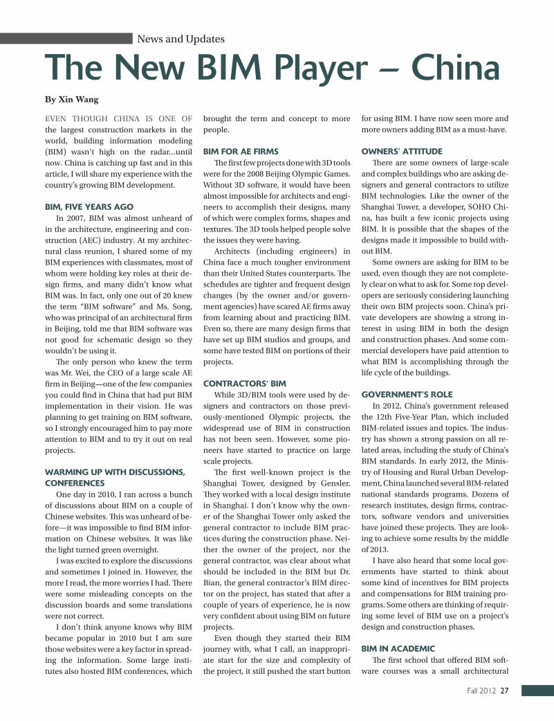
Fall 2012 27
News and Updates
The New BIM Player – ChinaEVEN THOUGH CHINA IS ONE OF the largest construction markets in the world, building information modeling (BIM) wasn’t high on the radar…until now. China is catching up fast and in this article, I will share my experience with the country’s growing BIM development.
BIM, FIVe yeaRS aGoIn 2007, BIM was almost unheard of
in the architecture, engineering and con-struction (AEC) industry. At my architec-tural class reunion, I shared some of my BIM experiences with classmates, most of whom were holding key roles at their de-sign firms, and many didn’t know what BIM was. In fact, only one out of 20 knew the term “BIM software” and Ms. Song, who was principal of an architectural firm in Beijing, told me that BIM software was not good for schematic design so they wouldn’t be using it.
The only person who knew the term was Mr. Wei, the CEO of a large scale AE firm in Beijing—one of the few companies you could find in China that had put BIM implementation in their vision. He was planning to get training on BIM software, so I strongly encouraged him to pay more attention to BIM and to try it out on real projects.
WaRMING UP WITh dISCUSSIoNS, CoNFeReNCeS
One day in 2010, I ran across a bunch of discussions about BIM on a couple of Chinese websites. This was unheard of be-fore—it was impossible to find BIM infor-mation on Chinese websites. It was like the light turned green overnight.
I was excited to explore the discussions and sometimes I joined in. However, the more I read, the more worries I had. There were some misleading concepts on the discussion boards and some translations were not correct.
I don’t think anyone knows why BIM became popular in 2010 but I am sure those websites were a key factor in spread-ing the information. Some large insti-tutes also hosted BIM conferences, which
brought the term and concept to more people.
BIM FoR ae FIRMSThe first few projects done with 3D tools
were for the 2008 Beijing Olympic Games. Without 3D software, it would have been almost impossible for architects and engi-neers to accomplish their designs, many of which were complex forms, shapes and textures. The 3D tools helped people solve the issues they were having.
Architects (including engineers) in China face a much tougher environment than their United States counterparts. The schedules are tighter and frequent design changes (by the owner and/or govern-ment agencies) have scared AE firms away from learning about and practicing BIM. Even so, there are many design firms that have set up BIM studios and groups, and some have tested BIM on portions of their projects.
CoNTRaCToRS’ BIMWhile 3D/BIM tools were used by de-
signers and contractors on those previ-ously-mentioned Olympic projects, the widespread use of BIM in construction has not been seen. However, some pio-neers have started to practice on large scale projects.
The first well-known project is the Shanghai Tower, designed by Gensler. They worked with a local design institute in Shanghai. I don’t know why the own-er of the Shanghai Tower only asked the general contractor to include BIM prac-tices during the construction phase. Nei-ther the owner of the project, nor the general contractor, was clear about what should be included in the BIM but Dr. Bian, the general contractor’s BIM direc-tor on the project, has stated that after a couple of years of experience, he is now very confident about using BIM on future projects.
Even though they started their BIM journey with, what I call, an inappropri-ate start for the size and complexity of the project, it still pushed the start button
for using BIM. I have now seen more and more owners adding BIM as a must-have.
oWNeRS’ aTTITUdeThere are some owners of large-scale
and complex buildings who are asking de-signers and general contractors to utilize BIM technologies. Like the owner of the Shanghai Tower, a developer, SOHO Chi-na, has built a few iconic projects using BIM. It is possible that the shapes of the designs made it impossible to build with-out BIM.
Some owners are asking for BIM to be used, even though they are not complete-ly clear on what to ask for. Some top devel-opers are seriously considering launching their own BIM projects soon. China’s pri-vate developers are showing a strong in-terest in using BIM in both the design and construction phases. And some com-mercial developers have paid attention to what BIM is accomplishing through the life cycle of the buildings.
GoVeRNMeNT’S RoleIn 2012, China’s government released
the 12th Five-year Plan, which included BIM-related issues and topics. The indus-try has shown a strong passion on all re-lated areas, including the study of China’s BIM standards. In early 2012, the Minis-try of Housing and Rural Urban Develop-ment, China launched several BIM-related national standards programs. Dozens of research institutes, design firms, contrac-tors, software vendors and universities have joined these projects. They are look-ing to achieve some results by the middle of 2013.
I have also heard that some local gov-ernments have started to think about some kind of incentives for BIM projects and compensations for BIM training pro-grams. Some others are thinking of requir-ing some level of BIM use on a project’s design and construction phases.
BIM IN aCadeMICThe first school that offered BIM soft-
ware courses was a small architectural
By Xin Wang

28 Journal of Building Information Modeling
school in Beijing. They started teaching BIM in 2007 and the first-year students have already graduated. Since then, many other schools have started to offer some kind of BIM software course. In 2012, at least one school started a masters for BIM.
INTeRNaTIoNal exChaNGeMany design firms (most design firms
are AE firms in China) are hesitant to im-plement BIM in their work processes. One main reason is that the current BIM tools are not compatible with Chinese regula-tions or standards. The other reason is that the Chinese version of the BIM software’s terms, menus and help files are poorly translated, so it’s very hard for people to learn the tools.
ChalleNGeSA major challenge is that most design
firms are hesitant to practice on real pro-jects so they often set up a BIM studio/group and let BIM guys work in parallel with the project’s teams. As a result, the project will have a BIM model but the pro-ject’s team will have had very limited ex-posure to BIM. Worse yet, this practice will often bring more costs to the project, since the BIM teams’ efforts will add extra cost and may not contribute much savings.
Another challenge is that almost all of the BIM modeling tools for design profes-sionals are imported. Users compare the inefficient BIM software with the “turbo-charged” Chinese CAD software and BIM doesn’t come out on top.
CoNClUSIoNThree years ago, BIM wasn’t heard of
in China. Now there have been achieve-ments using it. The most challenging issue that Chinese users are facing is not tech-nology but the recognition of the benefits that BIM would bring to us. I believe Chi-na is headed in this direction. n
Xin Wang is with AXTWo Internation-al LLC, a company which provides compre-hensive BIM solutions for building designers, engineers, contractors and owners, as well as facility managers.
Three years ago, BIM wasn’t heard of in China.
Now there have been achievements using it.
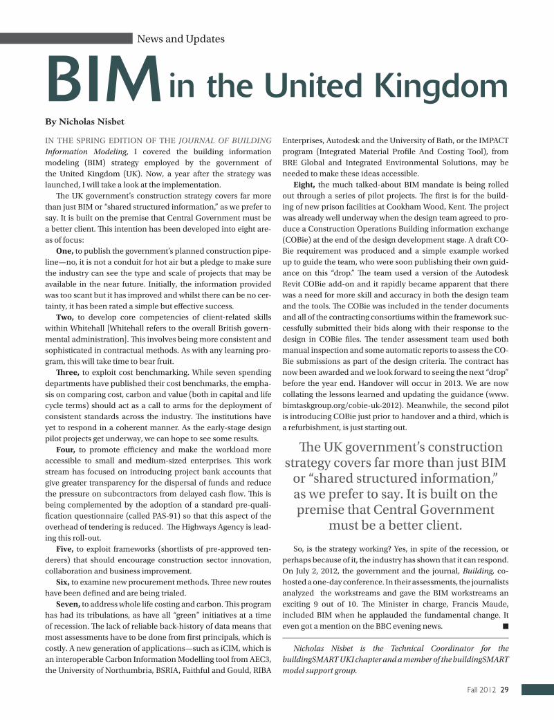
Fall 2012 29
News and Updates
IN THE SPRING EDITION OF THE JoURNAL oF BUILDING Information Modeling, I covered the building information modeling (BIM) strategy employed by the government of the United Kingdom (UK). Now, a year after the strategy was launched, I will take a look at the implementation.
The UK government’s construction strategy covers far more than just BIM or “shared structured information,” as we prefer to say. It is built on the premise that Central Government must be a better client. This intention has been developed into eight are-as of focus:
one, to publish the government’s planned construction pipe-line—no, it is not a conduit for hot air but a pledge to make sure the industry can see the type and scale of projects that may be available in the near future. Initially, the information provided was too scant but it has improved and whilst there can be no cer-tainty, it has been rated a simple but effective success.
Two, to develop core competencies of client-related skills within Whitehall [Whitehall refers to the overall British govern-mental administration]. This involves being more consistent and sophisticated in contractual methods. As with any learning pro-gram, this will take time to bear fruit.
Three, to exploit cost benchmarking. While seven spending departments have published their cost benchmarks, the empha-sis on comparing cost, carbon and value (both in capital and life cycle terms) should act as a call to arms for the deployment of consistent standards across the industry. The institutions have yet to respond in a coherent manner. As the early-stage design pilot projects get underway, we can hope to see some results.
Four, to promote efficiency and make the workload more accessible to small and medium-sized enterprises. This work stream has focused on introducing project bank accounts that give greater transparency for the dispersal of funds and reduce the pressure on subcontractors from delayed cash flow. This is being complemented by the adoption of a standard pre-quali-fication questionnaire (called PAS-91) so that this aspect of the overhead of tendering is reduced. The Highways Agency is lead-ing this roll-out.
Five, to exploit frameworks (shortlists of pre-approved ten-derers) that should encourage construction sector innovation, collaboration and business improvement.
Six, to examine new procurement methods. Three new routes have been defined and are being trialed.
Seven, to address whole life costing and carbon. This program has had its tribulations, as have all “green” initiatives at a time of recession. The lack of reliable back-history of data means that most assessments have to be done from first principals, which is costly. A new generation of applications—such as iCIM, which is an interoperable Carbon Information Modelling tool from AEC3, the University of Northumbria, BSRIA, Faithful and Gould, RIBA
Enterprises, Autodesk and the University of Bath, or the IMPACT program (Integrated Material Profile And Costing Tool), from BRE Global and Integrated Environmental Solutions, may be needed to make these ideas accessible.
Eight, the much talked-about BIM mandate is being rolled out through a series of pilot projects. The first is for the build-ing of new prison facilities at Cookham Wood, Kent. The project was already well underway when the design team agreed to pro-duce a Construction Operations Building information exchange (COBie) at the end of the design development stage. A draft CO-Bie requirement was produced and a simple example worked up to guide the team, who were soon publishing their own guid-ance on this “drop.” The team used a version of the Autodesk Revit COBie add-on and it rapidly became apparent that there was a need for more skill and accuracy in both the design team and the tools. The COBie was included in the tender documents and all of the contracting consortiums within the framework suc-cessfully submitted their bids along with their response to the design in COBie files. The tender assessment team used both manual inspection and some automatic reports to assess the CO-Bie submissions as part of the design criteria. The contract has now been awarded and we look forward to seeing the next “drop” before the year end. Handover will occur in 2013. We are now collating the lessons learned and updating the guidance (www.bimtaskgroup.org/cobie-uk-2012). Meanwhile, the second pilot is introducing COBie just prior to handover and a third, which is a refurbishment, is just starting out.
So, is the strategy working? yes, in spite of the recession, or perhaps because of it, the industry has shown that it can respond. On July 2, 2012, the government and the journal, Building, co-hosted a one-day conference. In their assessments, the journalists analyzed the workstreams and gave the BIM workstreams an exciting 9 out of 10. The Minister in charge, Francis Maude, included BIM when he applauded the fundamental change. It even got a mention on the BBC evening news. n
Nicholas Nisbet is the Technical Coordinator for the buildingSMART UKI chapter and a member of the buildingSMART model support group.
BIMBy Nicholas Nisbet
in the United Kingdom
The UK government’s construction strategy covers far more than just BIM
or “shared structured information,” as we prefer to say. It is built on the premise that Central Government
must be a better client.

30 Journal of Building Information Modeling
Architectural and Engineering
Firms
ACAI Technologies, Inc. .................9
BIM Consulting and
Implementation
Kristine Fallon
Associates, Inc. ..........................30
Microsol Resources
Corporation .................................24
BIM Object Libraries and
Systems
Arcat ..............................................12
BIM Software
ArchiDATA ....................................28
CAD Masters, Inc. ...........................4
Design Data, Inc. .............................6
Graphisoft ....................................IFC
Green BIM .....................................17
BIM Software, Consultants
and Implementation
Kelar Pacific LLC ...........................19
BIM, Training and
Consulting
Eppstein Uhen Architects ............15
BIM/Model Checking
and Analysis
Solibri LLC .................................OBC
Construction Productivity
Software
Constructivity ...............................14
Design Innovation Services
and Consulting
New Tapestry LLC ........................26
HVAC Specialists
Cadvantage Drafting Service .......26
Leading Multi Disciplinary
BIM Solutions
Bentley Systems, Incorporated ......3
National Construction
Associations
American Institute of Steel
Construction .................................8
Associated General
Contractors .............................. IBC
Buyer’s Guide
provided a clear way to depict the exchange of information over time and what goes into the BIM model. Some of the benefits are: • It is a clear visual display of how the information flows;• It collects and disseminates information to the right people at
the right time;• It serves as a common language for all participants; and• It helps to manage interfaces between disciplines and trades.
eNRICh BIM WITh PRoFoUNd kNoWledGe FRoM TRade CoNTRaCToRS
The IPDT has strived to build trade knowledge into design models. The team focused on optimizing the design by pull-ing the high-quality information from the supply chain. Fol-lowing are two examples of how the structural BIM model is enriched thru the collaboration between the structural engi-neer, Degenkolb Engineers, and the steel fabricator, The Her-rick Corporation:1. The automated bill of materials (BoM) allowed the team to
identify and quantify constraints on material availability. By overlaying the BoM with rolling schedules from foreign and domestic mills, Herrick Corporation segregated and priced the materials based on source.
2. Degenkolb Engineers “tagged” structural elements in the structural design model by system (gravity and lateral) to identify those structural elements that require supplemental seismic provisions, such as impact testing and special weld in-spection, from gravity elements, where no such requirement
exists. Although the premium may only be $20 or $30 per ton, this is a substantial variable on a 10,000-ton project.
IMPRoVe BIM WITh oRGaNIzaTIoNal leaRNINGVery early in the project, the IPDT realized the need to
collectively develop a BIM Execution Plan that would define the framework, deliverables and work flows. The result is a project-specific standard operating procedure (SOP) manu-al for all elements of the BIM toolset. Due to the size and du-ration of the project, the team also recognized that there will be changes in processes, hardware and software over its life cycle.
The execution plan and process maps are the basis of contin-uous improvement because they outline the BIM workflow. To engage all key players and promote group discussions, the IPDT came together regularly at “plus/delta” sessions to discuss what worked (plus) and what can be improved (delta).
CoNClUSIoNOur industry is going through a fundamental transforma-
tion and Sutter Health and the CHH team chose to embrace this. The result was the creation of a collaborative and inno-vative project team, which became a high-performing team through the implementation of a collaborative delivery pro-cess and BIM technologies. n
Baris Lostuvali is the Senior Project Manager, of the Cathe-dral Hill Hospital Project. Reach him at at [email protected]. Michelle Hofmann is a VDC Specialist on the Cathedral Hill Hospital Project. Reach her at [email protected].
Continued from page 22
Buyer’s Guide