BUILDING BUILDING ISOLATION ISOLATION
17
APPLICATIONS CONSTRUCTION - BUILDING ISOLATION Why might you need to isolate all or part of a building? What is the typical budget to isolate a building? There are various reasons why building isolation may need to be considered; > Increasing urban densities leading to developments near to rail, other transport infrastructure or industrial developments > The need to maximise value per unit area by creating multifunctional spaces in confined areas > Tighter legislation > Increasing demands for quality and building function > Tendency towards lighter, cheaper structures that use less materials As an alternative to isolating the building structure one could consider isolating specific rooms by way of a floating floor or full boxinbox solution as set out in our Floating Floor section. This can vary significantly based on the size, type and quantity of isolators required. If only parts of the building require isolation then the impact can be minimal. However if the entire building or significant portions are required to be isolated then the overall budget can be significant with the supply of isolation products comprising as much as 1-2% of the overall development cost. AP-SVI-Building Isolation-13a BUILDING ISOLATION
Transcript of BUILDING BUILDING ISOLATION ISOLATION
APPLICATIONSCO
NST
RU
CTIO
N
- B
UIL
DIN
G I
SOLA
TIO
N
Why might you need to isolate all or part of a building?
What is the typical budget to isolate a building?
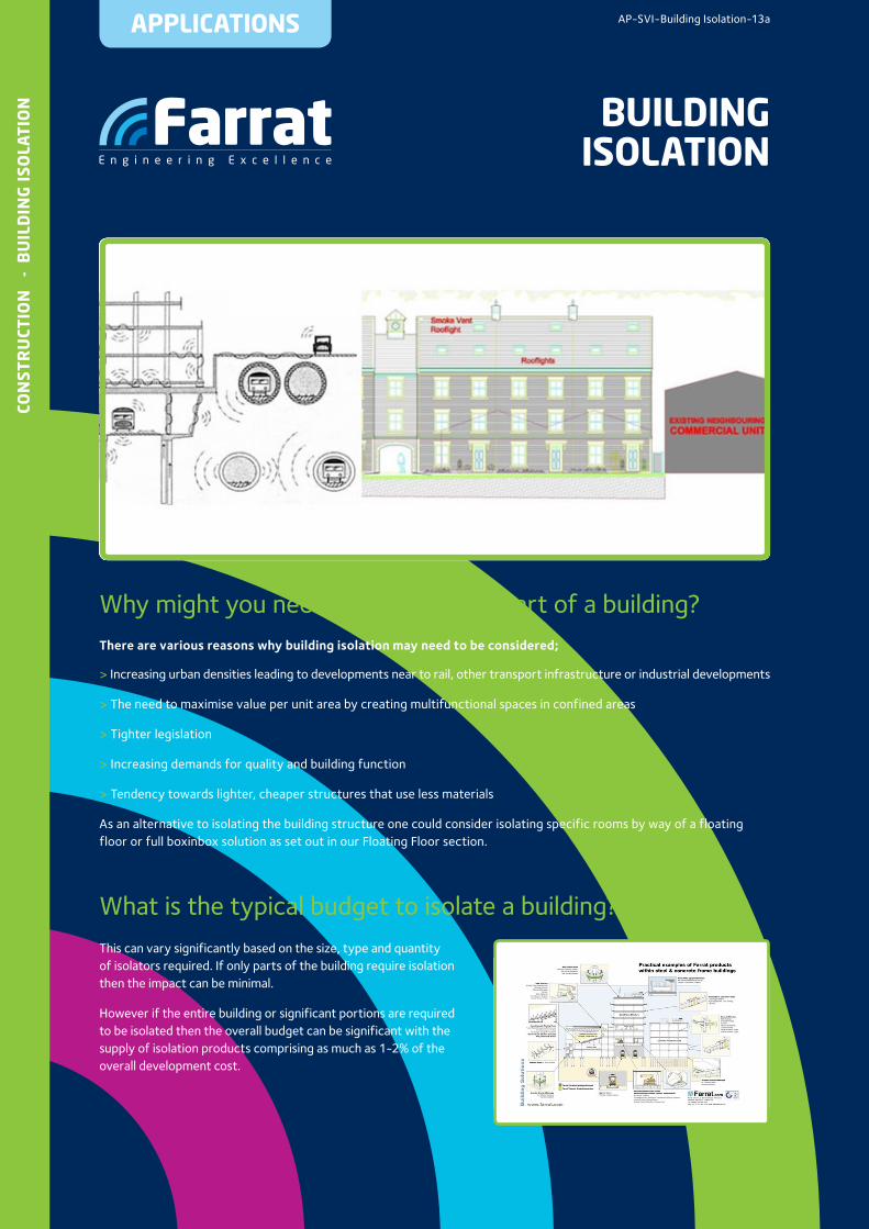
There are various reasons why building isolation may need to be considered;
> Increasing urban densities leading to developments near to rail, other transport infrastructure or industrial developments
> The need to maximise value per unit area by creating multifunctional spaces in confined areas
> Tighter legislation
> Increasing demands for quality and building function
> Tendency towards lighter, cheaper structures that use less materials
As an alternative to isolating the building structure one could consider isolating specific rooms by way of a floating floor or full boxinbox solution as set out in our Floating Floor section.
This can vary significantly based on the size, type and quantity of isolators required. If only parts of the building require isolation then the impact can be minimal.
However if the entire building or significant portions are required to be isolated then the overall budget can be significant with the supply of isolation products comprising as much as 1-2% of the overall development cost.
AP-SVI-Building Isolation-13a
BUILDING ISOLATION
01
CON
STR
UCT
ION
-
BU
ILD
ING
ISO
LATI
ON What should be considered in the design
of an isolated building or structure?
Vibration control is an inherent part of a structure and should ideally be considered at the early stages of the building design with the following factors to be considered;
• What are the acoustic criteria for the parts of the building that need to be isolated?
• Hotels, education and performing arts venues often have operator specific specifications
• Residential and office buildings may need to consider standards such as:
• BS6472 (Guide to evaluation of human exposure to vibration in buildings)
• BS8233 (Sound insulation and noise reduction for buildings)
• APTA Guidelines for groundbourne noise Levels inside residential dwellings (1981)
• What are the sources of the disturbing vibration?
• Rail
• Road
• Industrial
• Internal sources such as plant, circulation and active
zones etc.
• What are the characteristics of the disturbing vibration, the ground and the structure?
• Disturbing frequencies • Magnitude • Occurrence (continuous, intermittent or random)
• This data can usually be established by undertaking an acoustic and vibration survey provided by an acoustic consultant. Farrat can assist in planning the content of the survey and identifying a suitable consultant
• What parts of the building need to be isolated?
• The entire building
• If the ground floor is intended to be retail then this may not need to be isolated. The isolation can start at first or second floor level
• Sensitive or loud areas need to be isolated from adjacent internal areas
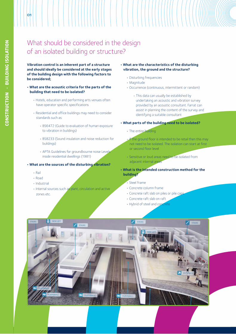
• What is the intended construction method for the building?
• Steel frame
• Concrete column frame
• Concrete raft slab on piles or pile caps
• Concrete raft slab on raft
• Hybrid of steel and concrete
02
CON
STRU
CTION
- BU
ILDIN
G ISO
LATIO
N
• How to ensure an effective vibration isolation design whilst ensuring complete integrity of the structural design and all connections to the foundations for safety, constructability and longevity?
• How to eradicate risks of isolation ‘bridging’ from:
• Lifts, shafts and rails
• Stair cases
• Services
• Ground floor interface connections
• Connections to neighbouring buildings or structures
• Shear walls
• Retained façade connections
• Internal and external cladding connections
• What construction tolerances are anticipated?
• The structure needs to be designed to have sufficient stiffness to maximise the use of the isolation system under all realistic load cases. This is usually achieved through modelling done by a structural engineer.
• If the isolation bearings need to be protected from fire. If so, to what standards and how?
• Any vibration control system can be damaged by fire however the approach to fire protection varies with each project. Protection from fire can be provided but it can make inspection all but impossible. This decision needs to be made in conjunction with the actual risk of fire reaching and damaging the isolators. Often the fire protection strategy is based on the incorporation of fail safes into the bearing assembly design to limit the total possible settlement.
• Bomb blast and crane crash protection can also be designed into the overall system but the actual solution will depend on the overall building design and the actual requirements.
• How to adequately incorporate, support fix and level the isolation bearings into the structure?
• Isolation Bearings and bearing arrays need to be levelled to +/- 1 mm across the face of the bearing array, and +/- 3mm across all bearings across each level.
• How to ensure the waterproofing will work with the decoupled structures and can be warranted?
• This can be a challenge and needs to be considered as part of the overall building design and construction as well as at each individual connection.
• If and how to design for inspection and replacement access?
• To enable inspection during installation, prior to commissioning and periodically during the life of the building.
• To replace the bearings if the structure were to be extended, modified or subject to a change of use significantly affecting bearing loadings.
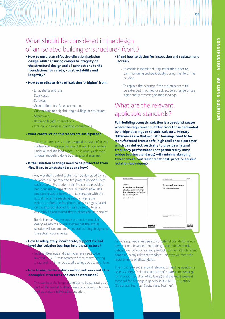
What are the relevant,applicable standards?Full-building acoustic isolation is a specialist sector where the requirements differ from those demanded by bridge bearings or seismic isolators. Primary differences are that acoustic bearings need to be manufactured from a soft, high resilience elastomer which can deflect vertically to provide a natural frequency performance (not permitted by most bridge bearing standards) with minimal damping (which would contradict most best-practice seismic isolation techniques).
Farrat’s approach has been to consider all standards which have some relevance then to design and independently validate our compounds and products to the most stringent condition in any relevant standard. This way we meet the requirements of all standards.
The most relevant standard relevant to building isolation is BS 6177:1982 (Selection and Use of Elastomeric Bearings for Vibration Isolation of Buildings) and the most relevant standard for bearings in general is BS EN 1337-3:2005 (Structural Bearings, Elastomeric Bearings).
What should be considered in the designof an isolated building or structure? (cont.)
03
CON
STR
UCT
ION
-
BU
ILD
ING
ISO
LATI
ON
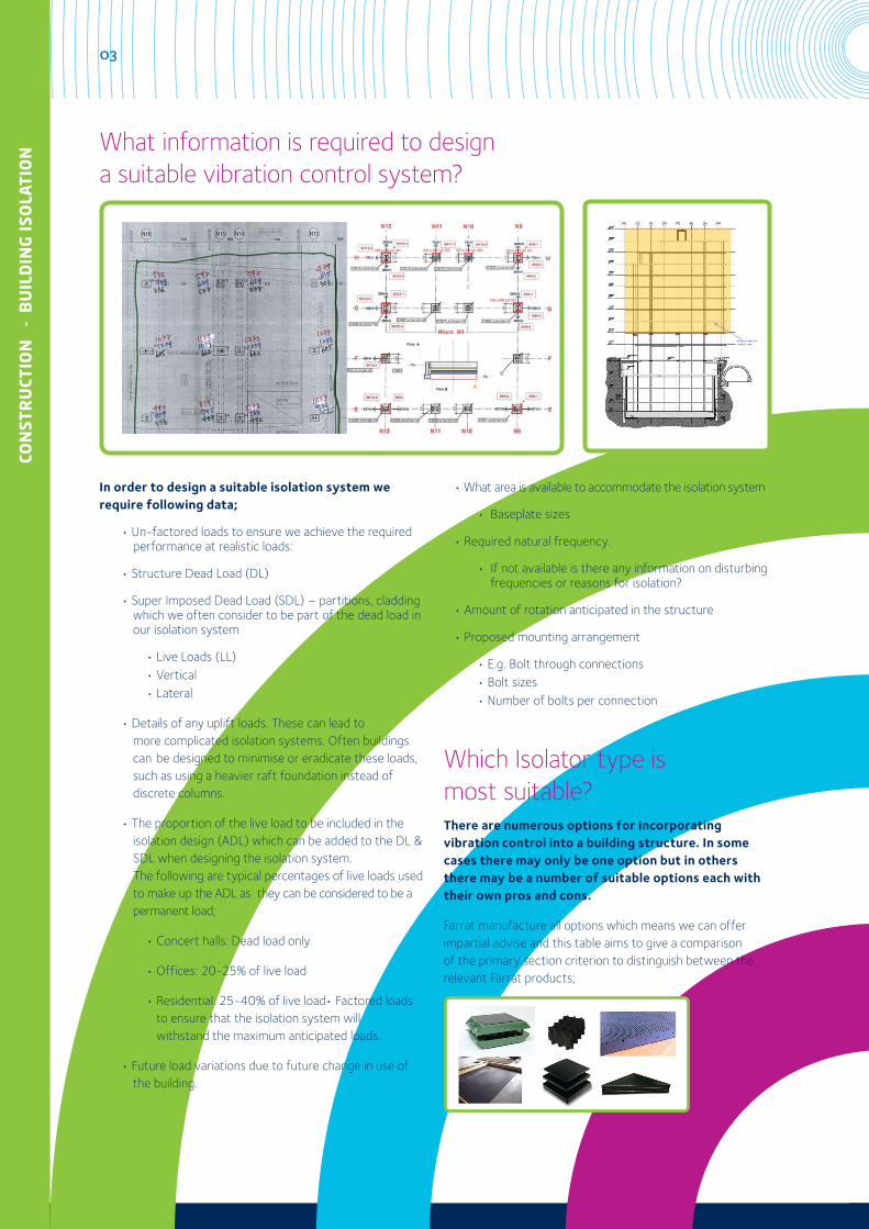
In order to design a suitable isolation system we require following data;
• Un-factored loads to ensure we achieve the required performance at realistic loads:
• Structure Dead Load (DL)
• Super Imposed Dead Load (SDL) – partitions, cladding which we often consider to be part of the dead load in our isolation system
• Live Loads (LL) • Vertical • Lateral
• Details of any uplift loads. These can lead to more complicated isolation systems. Often buildings can be designed to minimise or eradicate these loads, such as using a heavier raft foundation instead of discrete columns.
• The proportion of the live load to be included in the isolation design (ADL) which can be added to the DL & SDL when designing the isolation system. The following are typical percentages of live loads used to make up the ADL as they can be considered to be a permanent load;
• Concert halls: Dead load only
• Offices: 20-25% of live load
• Residential: 25-40% of live load• Factored loads to ensure that the isolation system will withstand the maximum anticipated loads.
• Future load variations due to future change in use of the building.
• What area is available to accommodate the isolation system
• Baseplate sizes
• Required natural frequency.
• If not available is there any information on disturbing frequencies or reasons for isolation?
• Amount of rotation anticipated in the structure
• Proposed mounting arrangement
• E.g. Bolt through connections • Bolt sizes • Number of bolts per connection
Which Isolator type ismost suitable?There are numerous options for incorporating vibration control into a building structure. In some cases there may only be one option but in others there may be a number of suitable options each with their own pros and cons.
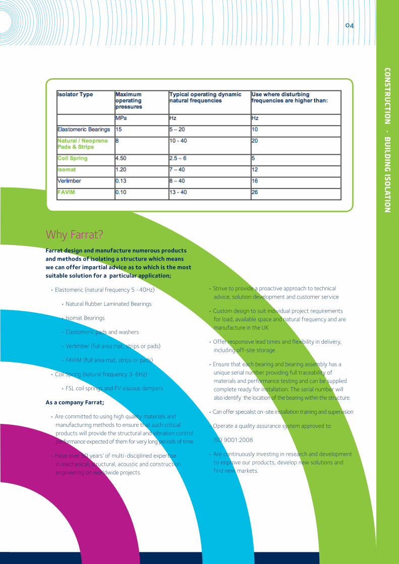
Farrat manufacture all options which means we can offer impartial advise and this table aims to give a comparison of the primary section criterion to distinguish between the relevant Farrat products;
What information is required to designa suitable vibration control system?
04
CON
STRU
CTION
- BU
ILDIN
G ISO
LATIO
N
Why Farrat?Farrat design and manufacture numerous products and methods of isolating a structure which means we can offer impartial advice as to which is the most suitable solution for a particular application;
• Elastomeric (natural frequency 5 -40Hz)
• Natural Rubber Laminated Bearings
• Isomat Bearings
• Elastomeric pads and washers
• Verlimber (full area mat, strips or pads)
• FAVIM (full area mat, strips or pads)
• Coil Spring (natural frequency 3-6Hz)
• FSL coil springs and FV viscous dampers
As a company Farrat;
• Are committed to using high quality materials and manufacturing methods to ensure that such critical products will provide the structural and vibration control performance expected of them for very long periods of time.
• Have over 50 years’ of multi-disciplined expertise in mechanical, structural, acoustic and construction engineering on worldwide projects
• Strive to provide a proactive approach to technical advice, solution development and customer service
• Custom design to suit individual project requirements for load, available space and natural frequency and are manufacture in the UK
• Offer responsive lead times and flexibility in delivery, including off-site storage
• Ensure that each bearing and bearing assembly has a unique serial number providing full traceability of materials and performance testing and can be supplied complete ready for installation. The serial number will also identify the location of the bearing within the structure.
• Can offer specialist on-site installation training and supervision
• Operate a quality assurance system approved to
ISO 9001:2008
• Are continuously investing in research and development to improve our products, develop new solutions and find new markets.
05
CON
STR
UCT
ION
-
BU
ILD
ING
ISO
LATI
ON
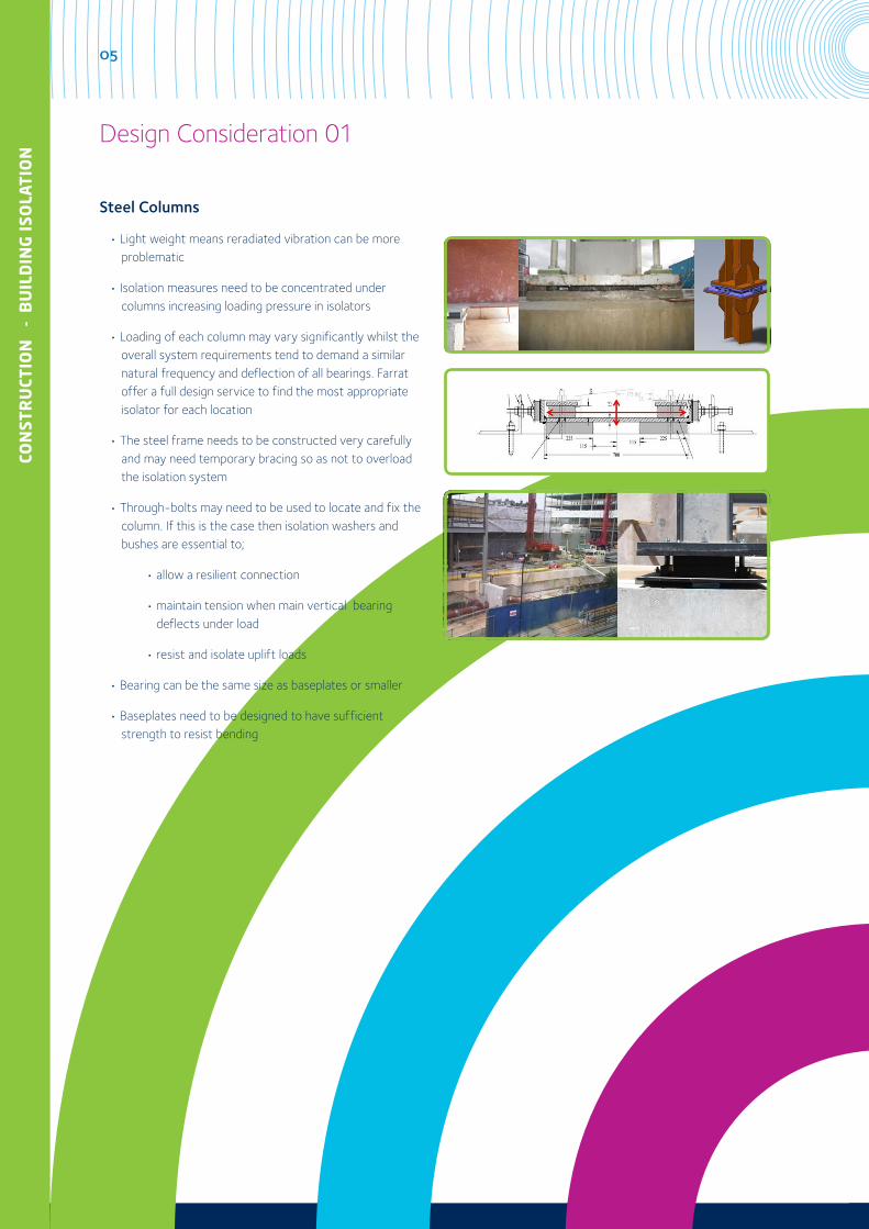
Steel Columns
• Light weight means reradiated vibration can be more problematic
• Isolation measures need to be concentrated under columns increasing loading pressure in isolators
• Loading of each column may vary significantly whilst the overall system requirements tend to demand a similar natural frequency and deflection of all bearings. Farrat offer a full design service to find the most appropriate isolator for each location
• The steel frame needs to be constructed very carefully and may need temporary bracing so as not to overload the isolation system
• Through-bolts may need to be used to locate and fix the column. If this is the case then isolation washers and bushes are essential to;
• allow a resilient connection
• maintain tension when main vertical bearing deflects under load
• resist and isolate uplift loads
• Bearing can be the same size as baseplates or smaller
• Baseplates need to be designed to have sufficient strength to resist bending
Design Consideration 01
06
CON
STRU
CTION
- BU
ILDIN
G ISO
LATIO
N
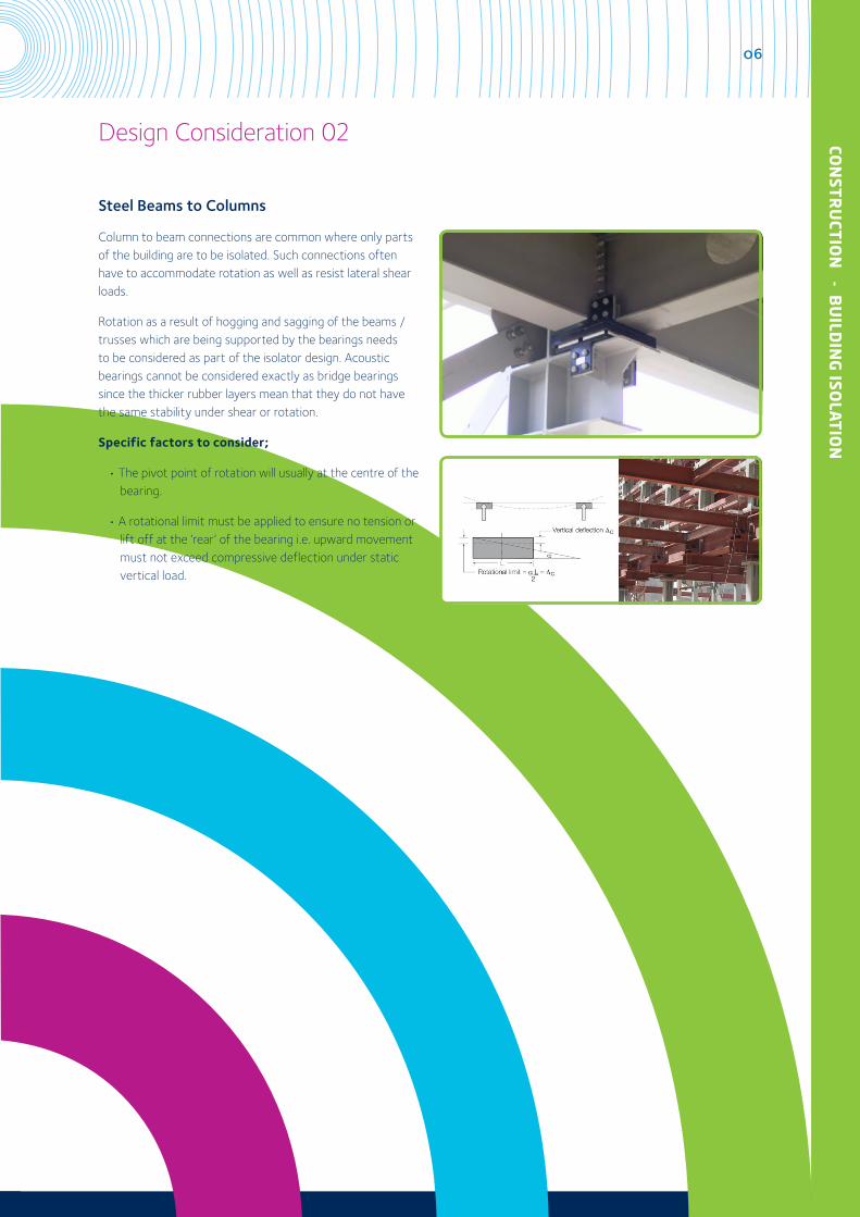
Steel Beams to Columns
Column to beam connections are common where only parts of the building are to be isolated. Such connections often have to accommodate rotation as well as resist lateral shear loads.
Rotation as a result of hogging and sagging of the beams / trusses which are being supported by the bearings needs to be considered as part of the isolator design. Acoustic bearings cannot be considered exactly as bridge bearings since the thicker rubber layers mean that they do not have the same stability under shear or rotation.
Specific factors to consider;
• The pivot point of rotation will usually at the centre of the bearing.
• A rotational limit must be applied to ensure no tension or lift off at the ‘rear’ of the bearing i.e. upward movement must not exceed compressive deflection under static vertical load.
Design Consideration 02
07
CON
STR
UCT
ION
-
BU
ILD
ING
ISO
LATI
ON
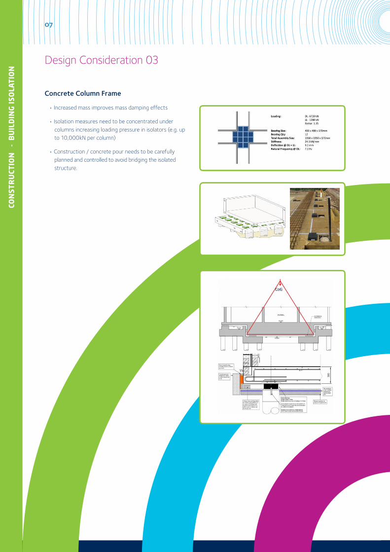
Concrete Column Frame
• Increased mass improves mass damping effects
• Isolation measures need to be concentrated under columns increasing loading pressure in isolators (e.g. up to 10,000kN per column)
• Construction / concrete pour needs to be carefully planned and controlled to avoid bridging the isolated structure.
Design Consideration 03
08
CON
STRU
CTION
- BU
ILDIN
G ISO
LATIO
N
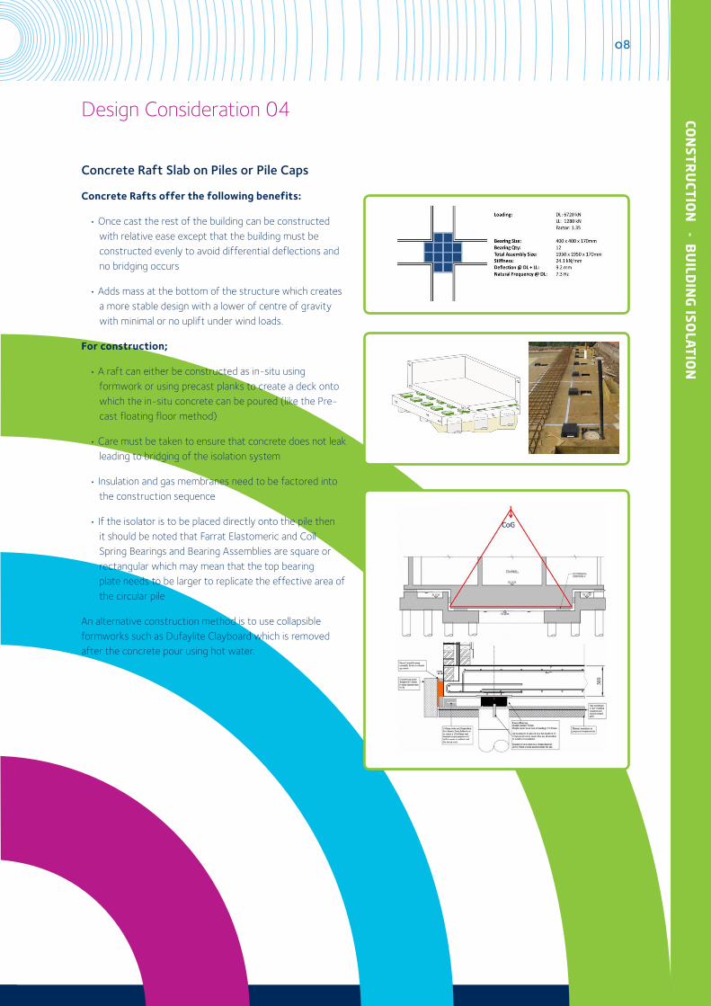
Concrete Raft Slab on Piles or Pile Caps
Concrete Rafts offer the following benefits:
• Once cast the rest of the building can be constructed with relative ease except that the building must be constructed evenly to avoid differential deflections and no bridging occurs
• Adds mass at the bottom of the structure which creates a more stable design with a lower of centre of gravity with minimal or no uplift under wind loads.
For construction;
• A raft can either be constructed as in-situ using formwork or using precast planks to create a deck onto which the in-situ concrete can be poured (like the Pre- cast floating floor method)
• Care must be taken to ensure that concrete does not leak leading to bridging of the isolation system
• Insulation and gas membranes need to be factored into the construction sequence
• If the isolator is to be placed directly onto the pile then it should be noted that Farrat Elastomeric and Coil Spring Bearings and Bearing Assemblies are square or rectangular which may mean that the top bearing plate needs to be larger to replicate the effective area of the circular pile
An alternative construction method is to use collapsible formworks such as Dufaylite Clayboard which is removed after the concrete pour using hot water.
Design Consideration 04
09
CON
STR
UCT
ION
-
BU
ILD
ING
ISO
LATI
ON
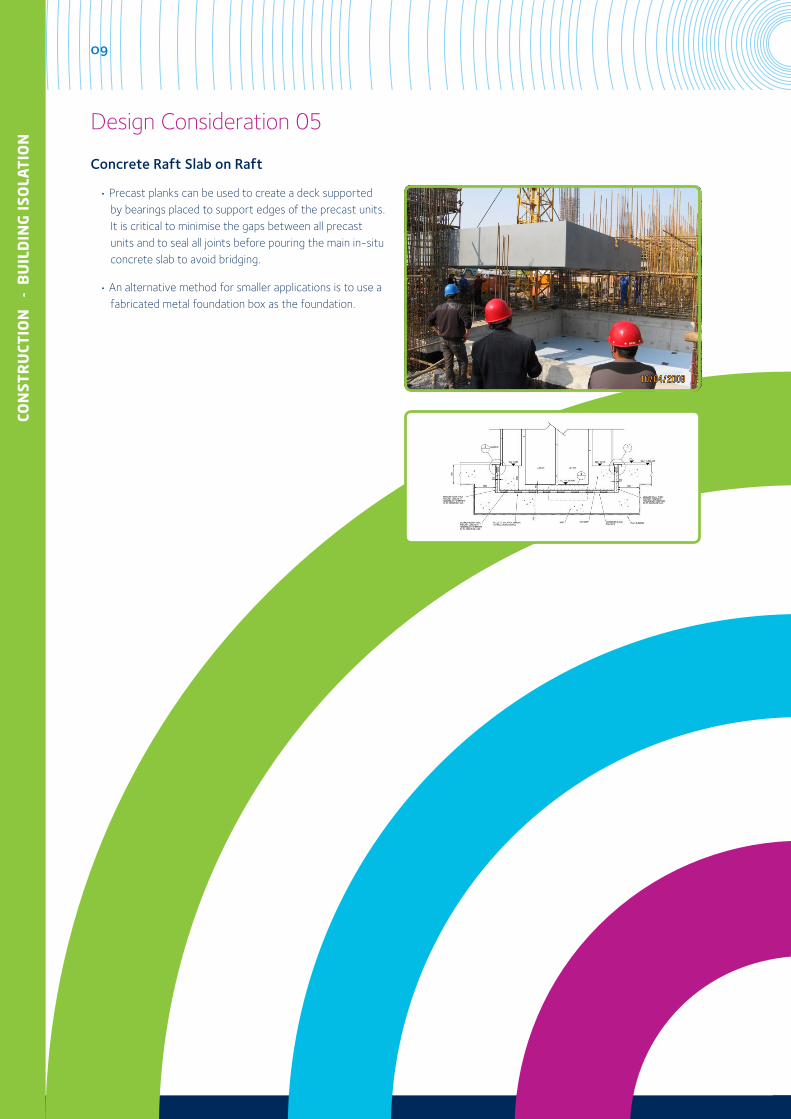
Concrete Raft Slab on Raft
• Precast planks can be used to create a deck supported by bearings placed to support edges of the precast units. It is critical to minimise the gaps between all precast units and to seal all joints before pouring the main in-situ concrete slab to avoid bridging.
• An alternative method for smaller applications is to use a fabricated metal foundation box as the foundation.
Design Consideration 05
10
CON
STRU
CTION
- BU
ILDIN
G ISO
LATIO
N
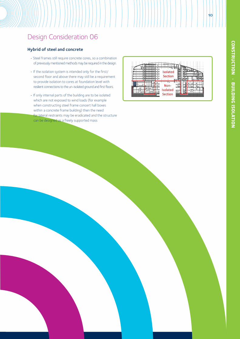
Hybrid of steel and concrete
• Steel frames still require concrete cores, so a combination of previously mentioned methods may be required in the design.
• If the isolation system is intended only for the first/ second floor and above there may still be a requirement to provide isolation to cores at foundation level with resilient connections to the un-isolated ground and first floors.
• If only internal parts of the building are to be isolated which are not exposed to wind loads (for example when constructing steel frame concert hall boxes within a concrete frame building) then the need for lateral restraints may be eradicated and the structure can be designed as a freely supported mass
Design Consideration 06
11
CON
STR
UCT
ION
-
BU
ILD
ING
ISO
LATI
ON
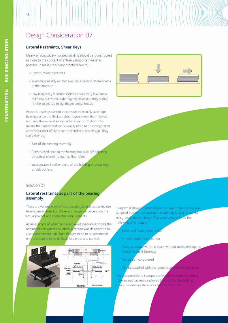
Lateral Restraints, Shear Keys
Ideally an acoustically isolated building should be constructed as close to the concept of a ‘freely supported mass’ as possible. In reality this is not practical due to;
• Construction tolerances
• Wind and possibly earthquake loads causing lateral forces in the structure
• Low frequency vibration isolators have very low lateral stiffness but when under high vertical load they should not be subjected to significant lateral forces.
Acoustic bearings cannot be considered exactly as bridge bearings since the thicker rubber layers mean that they do not have the same stability under shear or rotation. This means that lateral restraints usually need to be incorporated as a critical part of the structural and acoustic design. They can either be;
• Part of the bearing assembly
• Constructed next to the bearing but built off adjoining structural elements such as floor slabs
• Incorporated in other parts of the building as shear keys or slab buffers
Solution 01
Lateral restraints as part of the bearing assembly
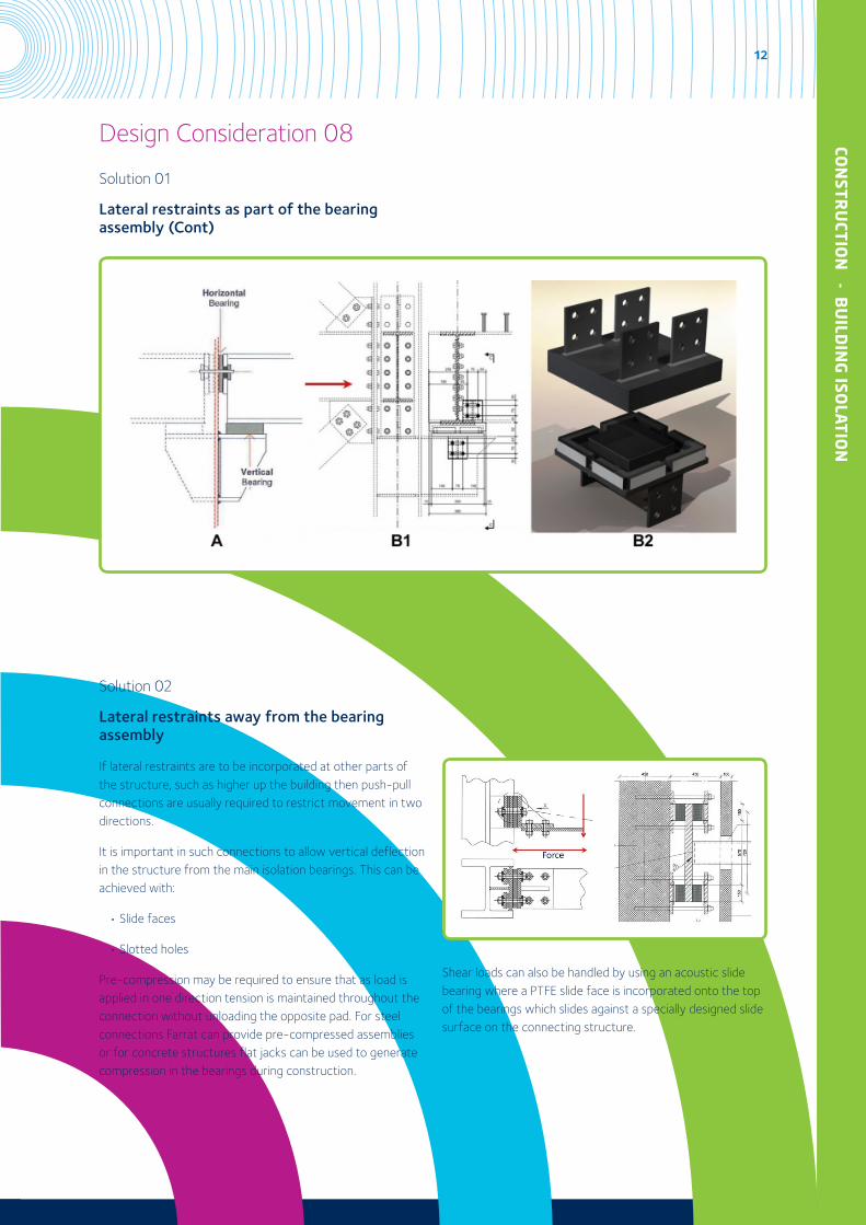
There are various ways of incorporating lateral restraints into bearing assemblies but the exact design will depend on the actual project and connection requirements.
As an example of what can be achieved Diagram A shows the original design where the lateral restraint was designed to be a separate connection. Such designs need to be assembled on site and tend to be difficult to a erect and control.
Diagram B shows a Farrat alternative where the bearing was supplied as a pre-assembled unit with the lateral restraints integrated into the design. This alternative offered the following advantages;
• Easier and faster construction
• A more resilient connection
• Ability to rotate with the beam without overstressing the lateral restraint bearings
• Fail-safes incorporated
• Can be supplied with pre-compressed lateral restraints
It is also possible to incorporate lateral restraints by adding fixtures such as resin anchored brackets to the building or using the existing structures such as floor slabs.
Design Consideration 07
12
CON
STRU
CTION
- BU
ILDIN
G ISO
LATIO
N
Solution 01
Lateral restraints as part of the bearing assembly (Cont)
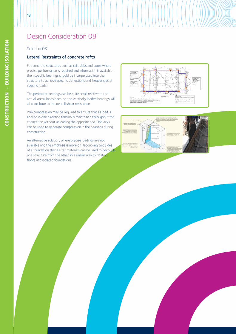
Solution 02
Lateral restraints away from the bearing assembly
If lateral restraints are to be incorporated at other parts of the structure, such as higher up the building then push-pull connections are usually required to restrict movement in two directions.
It is important in such connections to allow vertical deflection in the structure from the main isolation bearings. This can be achieved with:
• Slide faces
• Slotted holes
Pre-compression may be required to ensure that as load is applied in one direction tension is maintained throughout the connection without unloading the opposite pad. For steel connections Farrat can provide pre-compressed assemblies or for concrete structures flat jacks can be used to generate compression in the bearings during construction.
Shear loads can also be handled by using an acoustic slide bearing where a PTFE slide face is incorporated onto the top of the bearings which slides against a specially designed slide surface on the connecting structure.
Design Consideration 08
13
CON
STR
UCT
ION
-
BU
ILD
ING
ISO
LATI
ON
Solution 03
Lateral Restraints of concrete rafts
For concrete structures such as raft slabs and cores where precise performance is required and information is available then specific bearings should be incorporated into the structure to achieve specific deflections and frequencies at specific loads.
The perimeter bearings can be quite small relative to the actual lateral loads because the vertically loaded bearings will all contribute to the overall shear resistance.
Pre-compression may be required to ensure that as load is applied in one direction tension is maintained throughout the connection without unloading the opposite pad. Flat jacks can be used to generate compression in the bearings during construction.
An alternative solution, where precise loadings are not available and the emphasis is more on decoupling two sides of a foundation then Farrat materials can be used to decouple one structure from the other, in a similar way to floating floors and isolated foundations.
Design Consideration 08
14
CON
STRU
CTION
- BU
ILDIN
G ISO
LATIO
N
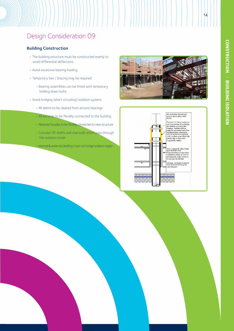
Building Construction
• The building structure must be constructed evenly to avoid differential deflections
• Avoid excessive bearing loading
• Temporary ties / bracing may be required
• Bearing assemblies can be fitted with temporary holding down bolts
• Avoid bridging (short circuiting) isolation system;
• All debris to be cleared from around bearings
• All services to be flexibly connected to the building
• Retained facades to be flexibly connected to new structure
• Consider lift shafts and stairwells which pass through the isolation break
• Internal & external cladding must not bridge isolation region
Design Consideration 09
15
CON
STR
UCT
ION
-
BU
ILD
ING
ISO
LATI
ON
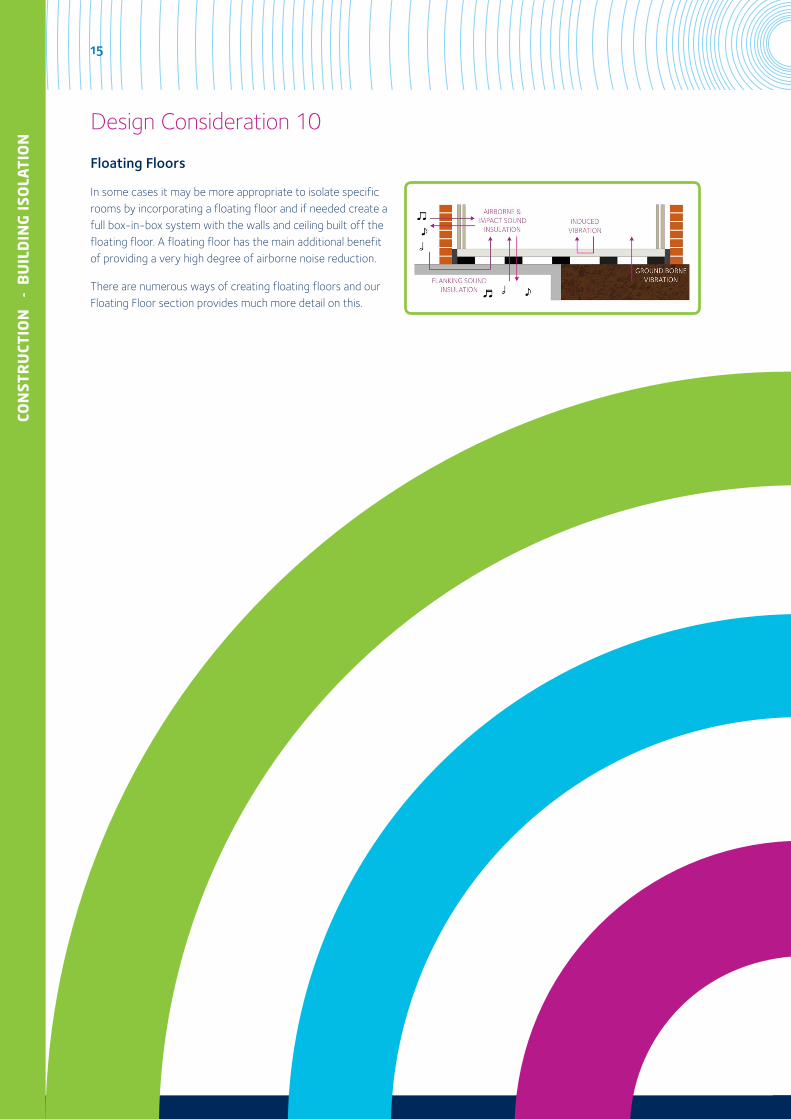
Floating Floors
In some cases it may be more appropriate to isolate specific rooms by incorporating a floating floor and if needed create a full box-in-box system with the walls and ceiling built off the floating floor. A floating floor has the main additional benefit of providing a very high degree of airborne noise reduction.
There are numerous ways of creating floating floors and our Floating Floor section provides much more detail on this.
Design Consideration 10

Farrat Isolevel Ltd Balmoral Road, Altrincham, Cheshire, WA15 8HJ, England, UKT. +44 (0) 161 924 1600 F. +44 (0) 161 924 1616
E. [email protected] www.farrat.com
Company Registration Number (England): 635283 VAT Registration Number: GB 145 9515 50
Company Directors: O. Farrell, A. Farrell, R.J. Farrell, H.J. Farrell, G.H. Farrell
Global experts in Vibration Control, Thermal Isolation &
Precision Levelling Solutions for Construction, Industry & Power Generation