
January/February 2004 Gear Technology 2004 The Journal of Gear Manufacturing LUBRICATION...
60
GEAR TECHNOLOGY The Journal of Gear Manufacturing JANUARY/FEBRUARY 2004 THE GEAR INDUSTRY’S INFORMATION SOURCE www.geartechnology.com LUBRICATION Understanding Fluid Flow to Improve Lubrication Efficiency Service Behavior of Coated Gearing CUTTING TOOLS New Potentials in Carbide Hobbing SOFTWARE BITS 8-Page Special Section PROFILE: Philadelphia Gear Corp. • Plus Revolutions, Addendum, Industry News, Product News and Technical Calendar
Transcript of January/February 2004 Gear Technology 2004 The Journal of Gear Manufacturing LUBRICATION...
GEAR TECHNOLOGYThe Journal of Gear ManufacturingJANUARY/FEBRUARY 2004
THE GEAR INDUSTRY’S INFORMATION SOURCE
www.geartechnology.com
LUBRICATIONUnderstanding Fluid Flow to ImproveLubrication Efficiency
Service Behavior of Coated Gearing
CUTTING TOOLSNew Potentials in Carbide Hobbing
SOFTWARE BITS8-Page Special Section
PROFILE: Philadelphia Gear Corp.• Plus Revolutions, Addendum, Industry News, Product News and Technical Calendar

GLEASON-PFAUTER FORM GRINDERSGIVE YOU THE EDGE
RReevvoolluuttiioonnaarryyDDeessiiggnn FFeeaattuurreess;;BBiigg SSaavviinnggss......
Save on Cycle Times...� On-machine dressing integrates
the dressing unit with the grinding head to ensure the highest level of repeatability. Compensation for wheel wear between dresses is automatic—and fast.
� On-machine inspection analyzes stock distribution, and compensatesfor heat treat distortion and partrunout. The grinding cycle isoptimized automatically.
� Designed with the flexibility to also grind internal and external gears with Gleason high-performanceplated CBN wheels.
� Dramatic reduction in setup time through automatic compensation of radial and axial runout. Time-intensive and costly manual alignment is eliminated.
� Proprietary (patent pending) system uses special measuring device and software to determine workpiece position relative to table and machine axes; automaticallycompensates for runout during machining.
For gear diameters from 400 to 4,000 mm, Gleason-Pfauter FormGrinders can take the time, cost and question marks out of yourprocess, and put more profitability in.
Call us, or visit www.gleason.com for real-worldexamples of this technology at work.
1000 University Ave., P.O. Box 22970 Rochester, NY 14607-1282 U.S.A.
Phone: 585/473-1000 Fax: 585/461-4348 Web site: www.gleason.com E-mail: [email protected]
NEW! Save on Setups...Compensation:
Eccentric Position Oblique Position
GLEASON BRINGS YOU THE LATEST TECHNOLOGYIN PLATED GRINDING WHEELS AND DRESSING TOOLS
leason Cutting Tools offers a new line of high-precision replatable CBNand diamond grinding
and dressing wheels, for use withany modern CNC gear profile, gearhoning or gear grinding machine.
This line of precision tools is available in a wide range of
designs, configurations and sizes to meet any special form or geargrinding application.
The use of Gleason single layerCBN technology helps deliverhigher stock removal rates, lower cost per workpiece, longerwheel life and more consistentquality. CMM verification of
ground coupons is available forthe highest quality assurance.
The investment in Gleason Cutting Tools’ new state-of-the-art precision plating facility assuresthe highest quality, consistency and faster deliveries.
For more information, contact:
G
C O R P O R A T I O N1351 Windsor Road Phone: 815-877-8900Loves Park, IL 61111 USA Fax: 815-877-0264Website: www.gleason.com E-Mail: [email protected]

GEAR TECHNOLOGYJANUARY/FEBRUARY 2004 The Journal of Gear Manufacturing
LUBRICATION
Understanding Fluid Flow to Improve Lubrication EfficiencyA study of pressure measurement in theroot space of helical gears..............................................................................................28
Service Behavior of PVD-Coated Gearing Lubricated With Biodegradable Synthetic Ester OilsUsing coated gears to eliminate environmentally hazardous oil additives.....................34
Company Profile: Philadelphia GearHow this cornerstone of the gear industry has adapted to changing times.....................15
Software BitsNews and information on the latest releases and updates in gear software....................20
New Potentials in Carbide HobbingOptimizing the tool for maximum productivity and reliability......................................42
Publisher’s PageRenaissance Man..............................................................................................................7
RevolutionsMagnetic filtration and more productive gear blanking...................................................9
Industry NewsThe latest news from the gear industry...........................................................................12
Technical CalendarDon’t miss these important upcoming events.................................................................41
Product NewsNew machines, tools and other products for the gear industry.......................................51
Advertiser IndexUse this directory to get information fast.......................................................................53
ClassifiedsServices, Help Wanted, Websites and more...................................................................54
AddendumUnsolved Gear Mysteries................................................................................................56
FEATURES
Cover photo courtesy of SigmaPool of Saline, MI.
28
56
DEPARTMENTS
20
KAPPTECHNOLOGIES
The best is now available.KAPP CBN wheels make any machine
more efficient, more productive, more profitable.
2870 Wilderness Place Ph: 303-447-1130
Boulder, Colorado 80301 www.kapp-usa.com Fx: 303-447-1131

4 JANUARY/FEBRUARY 2004 • GEAR TECHNOLOGY • www.geartechnology.com • www.powertransmission.com
EDITORIAL
Publisher & Editor-in-ChiefMichael Goldstein
Managing Editor William R. Stott
Associate Editor Joseph L. Hazelton
Assistant Editor Robin Wright
Editorial Consultant Paul R. Goldstein
Technical EditorsRobert Errichello
Don McVittieRobert E. SmithDan Thurman
ART
Art Director Jean Bartz
ADVERTISING
Advertising Manager Patricia Flam
Advertising CoordinatorCarol Tratar
CIRCULATION
Circulation CoordinatorCarol Tratar
INTERNET
Web Developer Dan MacKenzie
Gear Industry Home Page™ SalesPatricia Flam
powertransmission.com™ SalesClark Hopkins
RANDALL PUBLISHING STAFF
President Michael GoldsteinVice President Richard Goldstein
Accounting Dianne Borg
Phone: 847-437-6604E-mail: [email protected]: www.geartechnology.com
www.powertransmission.com
GEAR TECHNOLOGY, The Journal of GearManufacturing (ISSN 0743-6858) is published bimonthlyby Randall Publishing, Inc., 1425 Lunt Avenue, P.O. Box1426, Elk Grove Village, IL 60007, (847) 437-6604. Coverprice $5.00 U.S. Periodical postage paid at ArlingtonHeights, IL, and at additional mailing office (USPS No. 749-290). Randall Publishing makes every effort to ensure thatthe processes described in GEAR TECHNOLOGY conformto sound engineering practice. Neither the authors nor thepublisher can be held responsible for injuries sustained whilefollowing the procedures described. Postmaster: Sendaddress changes to GEAR TECHNOLOGY, The Journal ofGear Manufacturing, 1425 Lunt Avenue, P.O. Box 1426, ElkGrove Village, IL, 60007. ©Contents copyrighted by RAN-DALL PUBLISHING, INC., 2004. No part of this publica-tion may be reproduced or transmitted in any form or by anymeans, electronic or mechanical, including photocopying,recording, or by any information storage and retrieval sys-tem, without permission in writing from the publisher.Contents of ads are subject to Publisher’s approval.
VOL. 21, NO. 1
GEAR TECHNOLOGYThe Journal of Gear Manufacturing
Arrow Gearis one of the world'sleading suppliers ofgears and gearboxes to the aero-space industry with complete design capability, including finite element.Arrow’s latest success was utilizing ourstate-of-the-art technologies to design thegear tooth geometry and to manufactureall bevel gears in the PTO & AGB for Pratt & Whitney’s PW 6000 engine.
2301 Curtiss Street • Downers Grove, IL 60515Tel: (630) 969-7640 • Fax: (630) 969-0253
www.arrowgear.com
P & WF119 EMAD

Generating and form grinding, with dressable
or CBN tools,in one machine
High-performance gear grinding, with integrated dressing unit, allows generat-ing and form grinding with dressableand CBN tools in the same machine,with a capacity of 200/300mm dia. andup to an 8mm module. Combined withthe automatic loading/ unloading fea-ture, this machine is an efficient produc-tion unit with proven Liebherr reliability.
Gear Hobbing • Shaping • Grinding • Measuring
The Gearing Partnership of Liebherr, Klingelnberg and Oerlikon
SIGMA POOL
Liebherr Gear Technology Co.1465 Woodland DriveSaline, MI 48176-1259734.429.7225 • Fax [email protected]

6 JANUARY/FEBRUARY 2004 • GEAR TECHNOLOGY • www.geartechnology.com • www.powertransmission.com
• Threads, Helical and Involute • Straight or Tapered Splines • on Shafts & Production Rolling
SPLINE ROLLINGRACKS
• Helical, Spirex, Large Involutes, • Flat, Concave & Special Forms • Patented CNC Manufactured for •• Consistency
Colonial Tool Group, Inc. has been a leader in the machine tool industry for over 60 years.Our reputation can only be maintained by the manufacturing of all our products in-house,
including a complete heat treat facility. Let us tackle your tooling needs or process problems from our previous experience, balanced with today’s ingenuity.
4REASONS TO USECOLONIAL TOOL GROUP, INC.
COLONIAL
TOOLI N CGROUP
BROACHTOOLS
1
3
• Patented Motorized Boring, Milling,• Grinding & Cluster • • • Repair or Design & Build
PRECISION MACHINESPINDLES
• CNC Helical/Table Up, Pull Down, • Surface and Horizontal • Complete Turnkey Setups
BROACHINGMACHINES
2
4
1691 Walker RoadWindsor, Ontario
Canada N8W 3P1519-253-2461
FAX 519-253-5911
In the U.S.A.:5505 Concord Street
Detroit, MI 48211
12344 Delta DriveTaylor, MI 48180
313-965-8680www.colonialtool.com
Gear Production Specialists• Gear Shapers • Gear Hobbers • Gear Grinders •
• Full Remanufacture:• A brand new machine on highly stable,
naturally aged castings.
• CNC Retrofit for total process control. Maxperformance with minimal operator intervention:
• Up to 6-Axis of CNC machine control.• Thermal Compensation• Closed loop auto compensation from
post process and/or tool gages.
• Application Engineering:• Process development and cycle optimization.
• Field Service and Preventive Maintenance Plans
NO RISK – RESULTS GUARANTEED• Statistical run-off to your specifications.• 2 Year warranty, best in the industry.
VERMONT MACHINE TOOL®
Quality, Experience and Craftsmanship for over 20 yearsSpringfield, Vermont USA
802-885-4521www.vermontmachinetool.com
www.powertransmission.com • www.geartechnology.com • GEAR TECHNOLOGY • JANUARY/FEBRUARY 2004 7
PUBLISHER’S PAGE
Michael Goldstein, Publisher & Editor-in-Chief
Renaissance ManI lost a good friend in October—one that many of you might know. Carlo Costi of Sogimex S.A.S. in Caponago (Milano), Italy,
came out of the EMO show in Milan on October 28, caught a taxi and called his wife, Mariella, to tell her that he wasn’t feeling
well. He died—in the taxi—on the phone—talking to his wife. He was 60 years old.
Carlo was a gear machine tool merchant, widely known in the Italian gear manufacturing community and the worldwide Gleason
and machine tool dealer communities. He will be missed by those who knew him. I will miss him not only because of our business
relationship, but because, over the years, I got to know Carlo as a person.
He was a very unique man, who came from a unique background.
Carlo’s father, Marco, was an Italian Jew who left Italy with the rise of Mussolini and went to Cairo, Egypt. There he met Carlo’s
mother, Maria, a Roman Catholic. Their 1941 marriage was blessed by the Catholic Church with the understanding that their first-
born, who would be Carlo’s brother, Enrico, was to be raised Roman Catholic. Carlo, like his father, practiced Judaism. I’ve always
admired how comfortable each of these brothers was with the unusual religious makeup of their family. To each of them, it was
always perfectly natural having a brother and a parent with a different religion, which is probably rare today.
Both Enrico and Carlo were born in Cairo, and after the war, the family moved back to Milan. In 1950, Carlo’s father formed
Sogimex—at first a trading company and later a machine tool merchant. Enrico joined his father in 1962 for a short period, left,
and returned in 1970. My father had met Marco in the 1960s, and I met Marco and Enrico in the early 1970s.
Meanwhile, Carlo went to see the world. He came to America in the early 1960s, studying and then teaching philosophy in New
York. While his brother and father were working in the machine tool business, he enjoyed the freedom of the hippie generation,
studying, learning and teaching about a lot of the things that add richness to people’s lives. We met in the early ’80s.
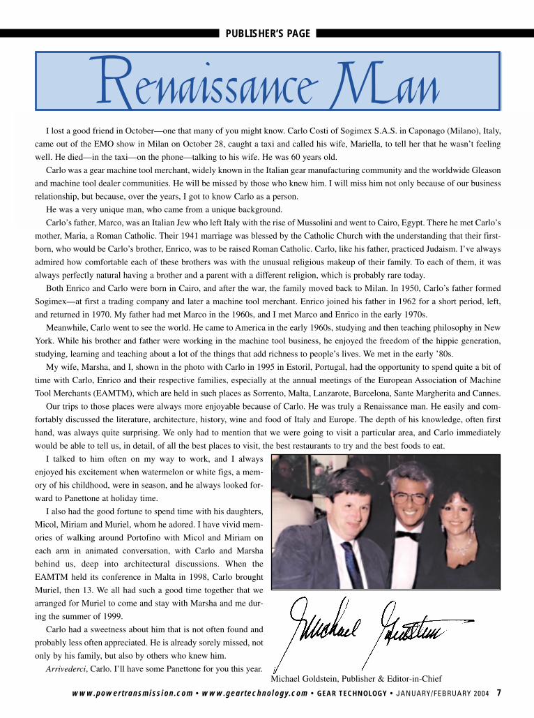
My wife, Marsha, and I, shown in the photo with Carlo in 1995 in Estoril, Portugal, had the opportunity to spend quite a bit of
time with Carlo, Enrico and their respective families, especially at the annual meetings of the European Association of Machine
Tool Merchants (EAMTM), which are held in such places as Sorrento, Malta, Lanzarote, Barcelona, Sante Margherita and Cannes.
Our trips to those places were always more enjoyable because of Carlo. He was truly a Renaissance man. He easily and com-
fortably discussed the literature, architecture, history, wine and food of Italy and Europe. The depth of his knowledge, often first
hand, was always quite surprising. We only had to mention that we were going to visit a particular area, and Carlo immediately
would be able to tell us, in detail, of all the best places to visit, the best restaurants to try and the best foods to eat.
I talked to him often on my way to work, and I always
enjoyed his excitement when watermelon or white figs, a mem-
ory of his childhood, were in season, and he always looked for-
ward to Panettone at holiday time.
I also had the good fortune to spend time with his daughters,
Micol, Miriam and Muriel, whom he adored. I have vivid mem-
ories of walking around Portofino with Micol and Miriam on
each arm in animated conversation, with Carlo and Marsha
behind us, deep into architectural discussions. When the
EAMTM held its conference in Malta in 1998, Carlo brought
Muriel, then 13. We all had such a good time together that we
arranged for Muriel to come and stay with Marsha and me dur-
ing the summer of 1999.
Carlo had a sweetness about him that is not often found and
probably less often appreciated. He is already sorely missed, not
only by his family, but also by others who knew him.
Arrivederci, Carlo. I’ll have some Panettone for you this year.

Warm Up ToForest City GearAnd Find World Class Quality!
Hornby Creek, Wisconsin
Between A Rock And A Cold Place?Between A Rock
And A Cold Place?
NEW: Face Gear Cutting Gleason CNC 500 mm,Helical Guideless Shaper with Taper Cutting,Special Accuracy and 200 mm Stroke
• Single Flank & Acoustical Gear Inspection
• Form Grinding Gears, Worms and Internals
11715 Main StreetP. O. Box 80 • Roscoe, Illinois 61073-0080
Toll Free 866-623-2168 • 815-623-2168 • Fax 815-623-6620www.fcgear.com • ISO 9001:2000 REGISTERED
Page 8 12/18/03 2:13 PM Page 1
REVOLUTIONS
Welcome to Revolutions, the col-
umn that brings you the latest, most
up-to-date and easy-to-read infor-
mation about the people and tech-
nology of the gear industry.
Revolutions welcomes your sub-
missions. Please send them to Gear
Technology, P.O. Box 1426, Elk
Grove Village, IL 60009, fax (847)
437-6618 or send e-mail to hazel-
Magnetic FiltrationFluid Conditioning Systems, of
Warwick, U.K., has developed a simpledevice to remove ferrous contaminantsfrom oil or transmission fluid with mini-mal reduction in fluid pressure.
The patented device, called theMagnom™, uses a magnetic field effect toremove particles as small as 0.07 micronsfrom a variety of fluid types and viscosi-ties. It was developed by a former RoyalAir Force engineer who was working inthe field of performance transmissions,according to Tom Hulme, CEO of FCS.
The engineer had been trying to solvethe problem of scoring on pistons and gearteeth. He needed a better way to removeferrous wear debris from the oil and trans-mission fluid. Conventional barrier filtra-tion methods created too big a pressuredrop, Hulme says. Another alternative,magnetic sump plugs, showed somepromise, but they couldn’t catch all thedebris. In addition, Hulme says, largelumps of debris can sometimes wash offmagnetic sump plugs and be reintroducedinto the system, causing damage.
www.powertransmission.com • www.geartechnology.com • GEAR TECHNOLOGY • JANUARY/FEBRUARY 2004 9
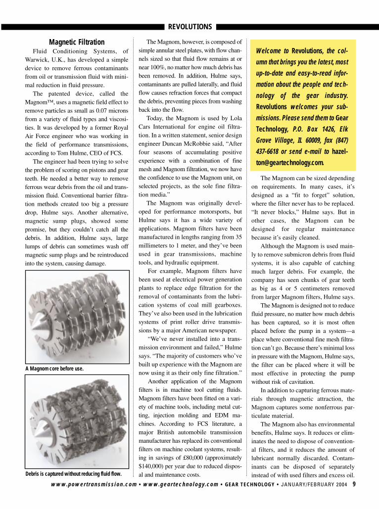
Debris is captured without reducing fluid flow.
The Magnom, however, is composed ofsimple annular steel plates, with flow chan-nels sized so that fluid flow remains at ornear 100%, no matter how much debris hasbeen removed. In addition, Hulme says,contaminants are pulled laterally, and fluidflow causes refraction forces that compactthe debris, preventing pieces from washingback into the flow.
Today, the Magnom is used by LolaCars International for engine oil filtra-tion. In a written statement, senior designengineer Duncan McRobbie said, “Afterfour seasons of accumulating positiveexperience with a combination of finemesh and Magnom filtration, we now havethe confidence to use the Magnom unit, onselected projects, as the sole fine filtra-tion media.”
The Magnom was originally devel-oped for performance motorsports, butHulme says it has a wide variety ofapplications. Magnom filters have beenmanufactured in lengths ranging from 35millimeters to 1 meter, and they’ve beenused in gear transmissions, machinetools, and hydraulic equipment.
For example, Magnom filters havebeen used at electrical power generationplants to replace edge filtration for theremoval of contaminants from the lubri-cation systems of coal mill gearboxes.They’ve also been used in the lubricationsystems of print roller drive transmis-sions by a major American newspaper.
“We’ve never installed into a trans-mission environment and failed,” Hulmesays. “The majority of customers who’vebuilt up experience with the Magnom arenow using it as their only fine filtration.”
Another application of the Magnomfilters is in machine tool cutting fluids.Magnom filters have been fitted on a vari-ety of machine tools, including metal cut-ting, injection molding and EDM ma-chines. According to FCS literature, amajor British automobile transmissionmanufacturer has replaced its conventionalfilters on machine coolant systems, result-ing in savings of £80,000 (approximately$140,000) per year due to reduced dispos-al and maintenance costs.
The Magnom can be sized dependingon requirements. In many cases, it’sdesigned as a “fit to forget” solution,where the filter never has to be replaced.“It never blocks,” Hulme says. But inother cases, the Magnom can bedesigned for regular maintenancebecause it’s easily cleaned.
Although the Magnom is used main-ly to remove submicron debris from fluidsystems, it is also capable of catchingmuch larger debris. For example, thecompany has seen chunks of gear teethas big as 4 or 5 centimeters removedfrom larger Magnom filters, Hulme says.
The Magnom is designed not to reducefluid pressure, no matter how much debrishas been captured, so it is most oftenplaced before the pump in a system—aplace where conventional fine mesh filtra-tion can’t go. Because there’s minimal lossin pressure with the Magnom, Hulme says,the filter can be placed where it will bemost effective in protecting the pumpwithout risk of cavitation.
In addition to capturing ferrous mate-rials through magnetic attraction, theMagnom captures some nonferrous par-ticulate material.
The Magnom also has environmentalbenefits, Hulme says. It reduces or elim-inates the need to dispose of convention-al filters, and it reduces the amount oflubricant normally discarded. Contam-inants can be disposed of separatelyinstead of with used filters and excess oil.
A Magnom core before use.
REVOLUTIONS
Despite the benefits, the cost of theMagnom is relatively small. The unit hasno moving parts, and the magnets andplates which make up the core are rela-tively inexpensive. Most of the cost ofthe unit is in the housing, Hulme says.Prices might range from $80 up to$7,000 for larger industrial systems.
“Like all good ideas, the cleverness isa function of the simplicity,” Hulme says.
Better Blanking from Bar StockIf you manufacture your own gear
blanks from barstock or outsource yourrequirements, Watkins Manufacturing ofCincinnati, OH, wants to talk to you.
The company’s SAW-Lutions™rotary saw cutting attachment can beadded to single- and multi-spindle auto-matic screw machines and CNC turningmachines to replace the traditional cutoff
method using single-point tooling. Theresult is a much faster, more efficientprocess that produces less waste andrequires less secondary work, says salesmanager Dirk Greulich.
“Almost any job that runs through ascrew machine, you’re going to experi-ence at least a 5–8% cost reduction onthe total cost of manufacturing,”Greulich says. “On parts such as gearblanks, or any part where the predomi-nant operation is cutting off, the savingscan be in excess of 30–50%.”
The attachment was first developedin the 1960s. Known also as the KerfCutter™ system, it has been used exten-sively in the screw machine industry,according to Greulich. But recently, thecompany has begun exploring how theprocess can help the gear industry.
The attachment mounts to a hostmachine and replaces conventional tool-ing with a rotating saw. As the stockturns, so does the saw.
Watkins Manufacturing believes inthe process so much that they have setup their own gear blanking operation toattract contract manufacturing work. If agear manufacturer wants to install rotarysawing systems on his machines,Watkins will supply them. The companyprovides ongoing service and support, aswell as on-site startup assistance witheach system. But if you normally buyyour gear blanks, Watkins believes it canmanufacture the blanks more efficientlythan companies that use other methods.
One of the benefits of the rotary sawcutoff method is that the cut is muchthinner than methods that use single-point tooling, Greulich says. Because ofthe thinner cut, manufacturers can real-
10 JANUARY/FEBRUARY 2004 • GEAR TECHNOLOGY • www.geartechnology.com • www.powertransmission.com
The SAW-LUTIONS™ rotary saw attachment.
REVOLUTIONS
www.powertransmission.com • www.geartechnology.com • GEAR TECHNOLOGY • JANUARY/FEBRUARY 2004 11
ize significant savings because less barstock is wasted. At least 8–10% materialsavings is experienced and, in somecases, bar stock usage can be cut by25–50% or more, Greulich says. Also,longer tool life and fewer tool changescontribute to long-term savings, he says.
Greulich adds that instead of longstrings of sharp metal, the rotary saw pro-duces very small, dustlike chips, that aremuch more disposable.
The process can become even moreproductive when multiple saws are run onthe same arbor. With gear blanking, it’scommon to cut two or three blanks at atime, Greulich says. But the company hasrun as many as 10 saws on a single arbor.
Another advantage of the rotary sawprocess is that it can typically cut fasterthan conventional tooling. “This initialimpact can drive cycle time down and pro-ductivity up substantially,” Greulich says.
Also, irregular shapes, such as extrudedbar stock or pinion stock, pose no specialproblems for rotary saw cutting, whereastraditional single-point tooling has a moredifficult time with start-and-stop edges.
In many cases, secondary machiningprocesses, such as double disk grinding,can be reduced or eliminated, because therotary saw attachment produces parts withbetter squareness, flatness and surface fin-ish than parts cut off with single-pointtooling, Greulich says. The cut-off surfaceflatness and squareness, he adds, can beheld to tolerances within 0.0003–0.002",depending on job characteristics.
The rotary saw attachment can be usedon a multi-spindle machine, so additionalmachining operations can be performedat the same time. Those operations mightinclude cutting blanks for shoulder gears,providing chamfers on the gear blank,drilling, reaming holes or OD work.
The process is ideal for volumes ofmore than 1,000 pieces, Greulich says.“But there really is no ramp-up. Eighty toninety percent of the savings are from gearone.” According to Greulich, there are evengreater efficiency gains when a machine isproducing the same part continuously overa period of a week or a month.
The Watkins rotary saw cutoff processhas been used on bar stock up to 4" indiameter and up to 30 Rc in hardness, butthe company is willing to “push the enve-lope,” Greulich says, “especially when it’swith materials we want to do R&D on.”
Saws for the attachment can be madeof high speed steel, tool steel or solidcarbide, and a variety of coatings,including TiN, TiAlN and TiCN, areavailable to enhance performance.
In addition to gear blanks, the processcan be used to make other high volume,precision turned parts, such as bearingraces, spacers, rollers or bushings.r
Tell Us What You Think . . . Send e-mail to [email protected] to• Rate this column• Request more information• Contact the people or organizations mentioned• Make a suggestion Or call (847) 437-6604 to talk to one of our edi-tors!
PATENTED PCD REINFORCINGFOR DIRECT PLATED DRESSERS
Distributed by:
Call or fax us your gear dresser requirements. You will quickly discover what leading U.S. gear producers have learned.
DR. KAISER gear dressers are the best value available.
401 Huger St., Columbia, SC 29201Phone: 1-800-775-1390 • Fax: 1-803-929-0507E-mail: [email protected]
WE also produce gear dressers for• Gleason TAG • Gleason Pfauter• & Gleason Phoenix• Liebherr• Klingelnberg• Oerlikon-Opal• Hoefler• Hurth• Kapp• Niles• Samputensili• Mikron• Maag• Csepel
We will design, build and guarantee from your gear summary charts gear dressers forReishauer SPA and Fassler DSA Systems—Direct-Plated or Sintered-Bond Single- orDouble-Sided Dressers.
We offer our customers• Highest Accuracy • Competitive Prices• Fastest Delivery • Relap & Replating Service

12 JANUARY/FEBRUARY 2004 • GEAR TECHNOLOGY • www.geartechnology.com • www.powertransmission.com
Wenzel Group Expands to Gear Metrology FieldThe Wenzel Group of Wiesthal, Germany, has founded a sub-
sidiary, Wenzel GearTech GmbH, for the gear metrology market.According to the company’s press release, the company
will start with 10 employees and will be managed by Hans-Helmut Rauth.
The new location will be used for design and development,sales and administration as well as a service base and democenter. Among the first products to be produced by the new sub-sidiary is a complete line of gear measuring machines with therequired mechanical components produced in the mother plant.
New Account Manager at InductoheatFlorie Schwartz was hired as account
manager at Inductoheat of MadisonHeights, MI.
Schwartz has previously worked in theinduction tube and pipe industry, accordingto the company’s press release.
Inductoheat designs and manufacturesinduction-heating equipment.
Ipsen Selected as John Deere SupplierIpsen International was chosen as the supplier of an atmos-
phere batch furnace line for the John Deere Waterloo Works.The facility will use the fully-automated heat treat line for gearcarburizing and agricultural equipment components.
According to Ipsen’s press release, John Deere will utilizeIpsen’s Iron Horse system to heat treat drivetrain gears andshafts distributed to manufacturing facilities worldwide.
The Iron Horse system includes the Carb-o-Prof real timecarbon diffusing modeling and control package. The systemalso includes multiple gas-fired TQF-2 double-chamber batchstraight through furnaces (size 17) with a rigid housing, posi-tive motion transfer mechanism, and a low-NOx combustionsystem using the company’s Recon III burners.
Headquartered in Rockford, IL, Ipsen manufactures thermalprocessing technologies.
New Sales Representative at Philadelphia GearMichael Bashour joined Philadelphia Gear in the newly cre-
ated position of southeast regional sales representative.Bashour previously worked as district sales manager at Duff-
Norton Co. and as a sales representative for Lufkin Industries.Among his new responsibilities will be leveraging the com-
pany’s technical expertise in the energy, mining, pulp andpaper, and rubber industries.
Lay Machinery and Service Network Form AgreementService Network Inc. (SNI) has appointed Lay Machinery
Systems as its exclusive representative for the state of Texas. Among the products for Lay to bring to the market are the
INDUSTRY NEWS
Florie SchwartzClydesdale Forge
Marriot Road, Dudley, West Midlands, DY2 0LA, UK
Tel: +(44) 1384 252587
Fax:+(44) 1384 231005
Website: www.clydesdale-forge.co.uk
E-mail: [email protected]
Clydesdale Forge is a world class manufacturer of ferrous
and non-ferrous forgings with an enviable reputation for
quality and on-time delivery backed up by the latest
technological and engineering support. From our two
manufacturing plants in the UK we already have a successful
track record of supplying major customers in North America.
• Excellent product quality
• On-time delivery
• Excellent value for money
• Experienced in Vendor Managed Inventory
• CAD, CAM, 3D simulation and modelling
• Carbon, alloy and stainless steel
• Duplex, super duplex, 6Mo steels, aluminium, bronze, nickel and titanium alloys
• On-site tooling, heat-treatment, NDT inspection and a UKAS accredited laboratory
• A large range of products for various markets such as:
- Commercial vehicles
- Off road vehicles
- Agriculture
- PPetrochemical and offshore drilling
- Nuclear
- Aerospace and defence
- General engineering
Give us call to see if we can meet your requirementGive us call to see if we can meet your requirementss
700+ pages of precision components designed for the fully integrated subsystems in today’s most demanding automated industries.
• Certified and Registered ISO 9001 RAB and RvA
• Certified Class 100 Clean Room• Certified New Hampshire Ball Bearing
Relube Facility
For a FREE Design Guide & CD with downloadable CAD drawings:Call 800-243-0986 or visit www.nordex.com
The Ultimate Design Guidefor the Creative Subsystems Designer
426 Federal Road • Brookfield, CT 06804 • Phone: (203) 775-4877 • Fax: (203) 775-6552www.nordex.com • Email: [email protected]
www.powertransmission.com • www.geartechnology.com • GEAR TECHNOLOGY • JANUARY/FEBRUARY 2004 13
Tell Us What You Think . . . Send e-mail to [email protected] to• Rate this article• Request more information• Contact the organizations mentioned• Make a suggestionOr call (847) 437-6604 to talk to one of our editors!
SN400-I internal and the SN200-E external production grinders.Both are targeted to manufacturers of bearings, automotive, aero-space, industrial and heavy equipment components.
SNI offers service, parts and remanufacturing for all Healdgrinders, which are available through Lay Machinery.
Lay Machinery of Dallas, TX, is involved in machine salesfor numerous metalworking machine tool manufacturers.
Ajax Tocco Gets Japanese ContractAjax Tocco Magnethermic of Warren, OH, and ATM JAMCO
of Tokyo, Japan, have been awarded a contract from Gohsyu ofTokyo, Japan, to supply a 2,000 kW induction billet heating system.
A key feature of the system is ATM’s enhanced hold circuit,which can hold billets at a temperature during press while prob-lems are corrected, according to Ajax Tocco Magnethermic’spress release.
The heater will be sent to Japan for installation and start-upin the second quarter of 2004.
mG miniGears and EPSCO Sign ContractmG miniGears reached an agreement with EPSCO Inc. for
representation in the automotive industry.According to mG miniGears’ press release, their recent
TS16949 certification played a large part in the decision to joinforces with EPSCO.
mG miniGears designs and manufactures custom engineeredgears and gearboxes for automotive, industrial and power toolcustomers.
New Appointments at TimkenThe Timken Co. of Canton, OH, announced several person-
nel changes effective in early 2004.Frank C. Sullivan was elected president and CEO of RPM
International, a division of The Timken Co. Sullivan has heldthe positions of COO, CFO and a variety of corporate develop-ment and sales positions within RPM since 1987.
Tim Timken Jr. was elected executive vice president andpresident of the steel group. He has worked for Timken since1992 in a variety of positions. For the last three years, he hasserved as corporate vice president and as a member of the boardof directors.
W.R. Timken Jr. announced his retirement from his positionas Timken executive officer. He will continue to serve on theboard of directors.r
INDUSTRY NEWS
FELLOWSSPARES
Mechanical guides: spur/helicalHydrostatic guides: spur/helical
YOUR SOLE RELIABLE SOURCE
Send yourrequest for quote to
Former Licensee manufacturer
Via Cimarosa 17—40033 Casalecchio di Reno (BO) Italyph 011 39 051 6117811 fax 011 39 051 6117808
www.decimaspa.it

An exact duplicate of every issue, including all the articles, ads and departments, available online at www.geartechnology.com.
Visit our website to subscribe today! E-GT will be prepared in PDF format. As a subscriber:
• You will be notified by e-mail when each issue’s content becomes available online.• You can download the entire issue or just the sections you want.• You can save the files of each issue to create your own electronic Gear Technology • archive.
E-GT! GEAR TECHNOLOGY
IS NOW AVAILABLE ONLINE
Subscribing to E-GT will not affect your print subscription to Gear Technology. You will still receive your printed magazine.
To sign up, look for the E-GT area at www.geartechnology.com
FREE to Qualified Readers Anywhere in the World
arge marine gearboxes. More than a year in production,each weighing 125,000 pounds, the gearboxes were forU.S. Navy amphibious ships, for combining the powerof 10,000 hp diesel engines to drive propeller shafts.
They were also the last major gear products shipped fromPhiladelphia Gear Corp.’s King of Prussia factory.
A mecca of the gear industry was closing. For more than 40years, the mammoth factory (625,000 square feet) was a sym-bol of Philly Gear. It was the embodiment of a company with along, storied history.
In 1892, Philly Gear was founded by gear pioneer George B.Grant, builder of the first hobbing machine for cutting spurgears. In 1916, it was one of nine gear companies to found theAmerican Gear Manufactuers Association. In World War II, itwas manufacturing 14-foot ring gears for battleship rotating gunturrets, for America’s “arsenal of democracy.”
In 2001, though, Philly Gear was struggling to survive, andits blue-and-white factory no longer fit into its future.
But the closing was part of a plan. Started in 1998, the plancalled for transforming then 106-year-old Philly Gear into acompany fit for the new economic order.
A New DirectionIn 1998, Philly Gear faced up to a growing problem. Foreign
competition was reducing the profitability of the U.S. gearindustry. Many products manufactured overseas were provingcheaper and equal or near equal to those manufactured in theUnited States. Jules DeBaecke, Philly Gear’s vice president ofengineering, summed up the situation: “Too many suppliers andnot enough customers.”
So the company decided on a new direction: serve the after-market. For Philly Gear, the aftermarket looked more profitablethan manufacturing gears for new industrial operations.
Also, the company appeared well positioned to serve theaftermarket needs of the energy industry through its satellitesites in California, Delaware, Illinois and Texas. Russ Ball,chairman and CEO of Philly Gear’s parent company, explainsthe sites were in areas populated with power plants. In the newstrategy, the sites would be made into regional service and man-ufacturing centers.
Today, Philly Gear’s top three industries are energy related:power generation, oil refining, and petrochemical.
As part of its new direction, Philly Gear changed its very
www.powertransmission.com • www.geartechnology.com • GEAR TECHNOLOGY • JANUARY/FEBRUARY 2004 15
Philly Gear: A Long Life, A New Direction
COMPANY PROFILE
LJoesph L. Hazelton
Philadelphia Gear Corp.Established: 1892No. of Employees: 150–200Industries Served: Power Generation, Oil Refining,
Petrochemical, Marine, CementMajor Products: Gear Drives, Helical Gears, Planetary
Gears, Spiral Bevel Gears, Straight Bevel Gears,Spur Gears
Quality Registrations: ISO 9001-2000 Website: www.philagear.com
Industry Affiliations• American Bearing Manufacturers Association (ABMA)• American Gear Manufacturers Association (AGMA)• American National Standards Institute (ANSI)• American Petroleum Institute• ASM International• ASME International• Association of Iron and Steel Engineers• ASTM International• Heat Treating Society• International Organization for Standardization (ISO)• Society for Mining, Metallurgy, and Exploration• Society of Naval and Marine Engineers

COMPANY PROFILE
16 JANUARY/FEBRUARY 2004 • GEAR TECHNOLOGY • www.geartechnology.com • www.powertransmission.com
nature, from its physical structure to its employees’ culture.A New Structure
The first major changes in structure came in ’01. InFebruary, Philly Gear moved its executive and engineering stafffrom the King of Prussia factory to an office suite in nearbyNorristown, another Pennsylvania city. In July, the last gearboxwas shipped from King of Prussia.
Besides closing the factory, Philly Gear added a regionalcenter in Alabama. Today, the five centers allow a national cus-tomer to deal with one company for all of its locations andallow a regional customer to use the center nearest its opera-tions. Also, the California center provides specialized gear man-ufacturing.
Changes in structure involved changes in personnel, too.Philly Gear declines to provide exact numbers, but it employsabout 10 percent fewer people today than it did in 2001.
Besides these changes, the company also brought its archiveinto the digital age.
A New ArchivePhilly Gear wanted its employees to have quicker, more
independent access to its records, to improve efficiency.Previously, Philly Gear’s archive was two iron mountains.
Filing cabinets filling two warehouses contained the company’spaperwork, including technical drawings, service records andsales information—some 600,000 paper documents. To accessthem, employees across the country faxed requests to theNorristown office.
If stored electronically, though, the archive could beaccessed directly by employees via computer. So Philly Geartook its papers and converted them into digital images, a $1 mil-lion project.
Today, engineers and other employees, in Norristown andelsewhere, have access to the documents via a password-pro-tected intranet.
In 2001, a factory gave way to an office suite. While reorganizing itself,Philadelphia Gear Corp. moved its headquarters from its King of Prussiafactory to a Norristown office building.
SOLD AND SERVICED BY:
Precise ProfilesPrecise ProfilesTRANSMECANICA Precision Tools
CONTACT:CRAIG D. ROSS(586) 754-8923
FAX (586) 754-8926
SPIRAL BEVEL GEARS(Transmissions)
Spiral & Straight Bevel Gear Manufacturing.Commercial to aircraft quality gearing.
Spur, helical, splined shafts, internal & external,shaved & ground gears. Spiral bevel grinding.
Midwest Transmissions & Reducers.ISO compliant & AS 9100 compliant.
MIDWEST GEAR& TOOL, INC.
12024 E. Nine Mile RoadWarren, MI 48089 [email protected]
COMPANY PROFILE
www.powertransmission.com • www.geartechnology.com • GEAR TECHNOLOGY • JANUARY/FEBRUARY 2004 17
Those records are useful to Philly Gear as an aftermarketsupplier whenever it’s called to service its brands of powertransmission products.
But Philly Gear services more than its own products. Thecompany expanded its repair and upgrade services to includemore than 30 other brands of products.
According to DeBaecke, serving many brands of productsincreased Philly Gear’s pool of possible customers.
Although focused on the aftermarket and the energy indus-try, the company still serves all industries on request and hasboth foreign and domestic customers. Industries still receivingnew Philly Gear products include power generation, sugar pro-cessing, rubber, cement, pulp and paper, petrochemical andmarine.
Aftermarket Services“They have excellent repair services,” Stephen Goodberry
says.Goodberry is lycra® maintenance planner for Invista Inc. He
plans all maintenance work for the fiber and chemical compa-ny’s lycra-making machines, including their gearboxes. He alsoobtains the parts to keep the machines running.
In his job, he’s worked directly with Philly Gear for 10-plusyears. In the past, he’s mainly used them as an OEM for newparts for new projects and for replacement parts. The last fewyears, though, he’s also been using them as an aftermarket sup-plier, in part for repair services.
And why are those services excellent? Quick replies to calls,listening well, and expedited, quality repairs, Goodberry says.
“Once it’s repaired,” he adds, “it’s fixed for good.”For example, three years ago, Goodberry learned of an
impending problem with the gear reducers in his lycra spinningmachines. Oil ferrography and vibration analysis showedexcessive gear wear in the boxes.
The problem:Invista hadn’t specifiedthe boxes correctly; theoil pumps weren’t theright size.
Goodberry contactedPhilly Gear, and the com-panies got to work on theproblem. They were look-ing at fixing 21 boxes inthe lycra division, locatedin Maitland, Ontario,Canada.
The boxes wereswitched out three at atime, sent to Philly Gear,who quickly turned themaround, and then put backin their machines. In
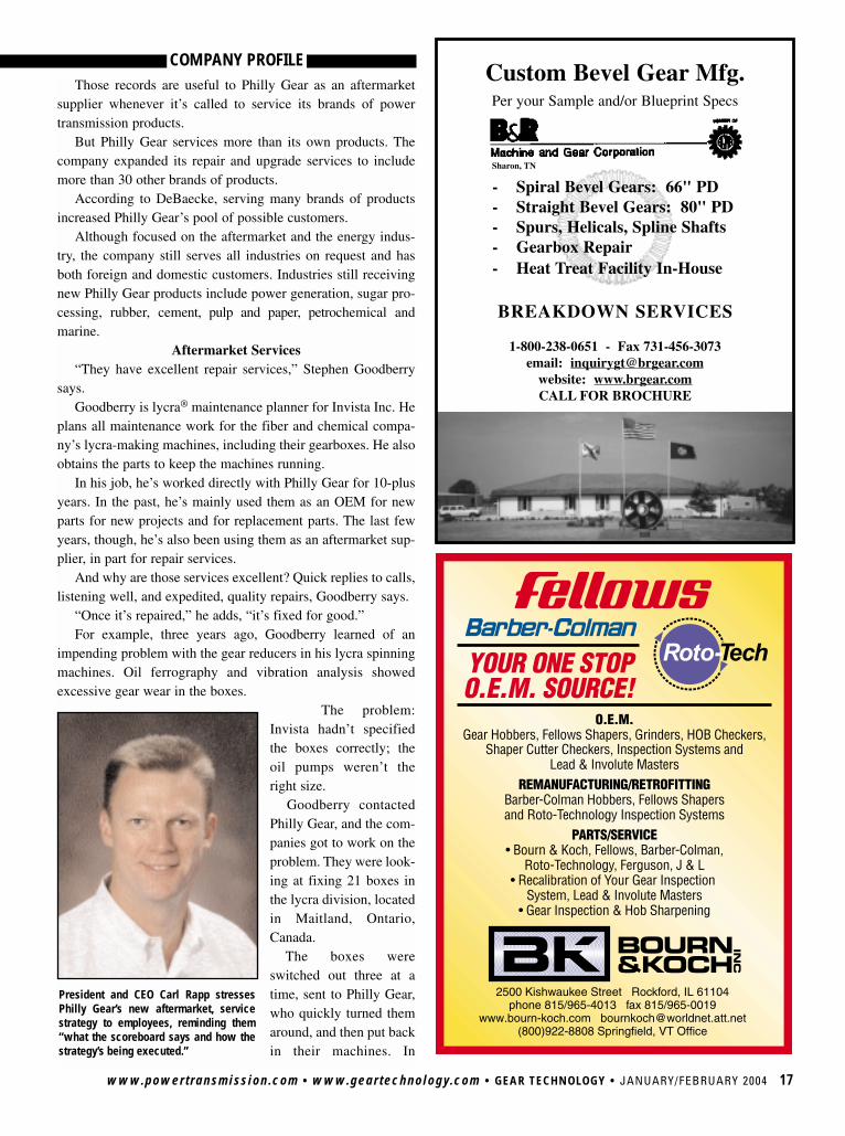
President and CEO Carl Rapp stressesPhilly Gear’s new aftermarket, servicestrategy to employees, reminding them“what the scoreboard says and how thestrategy’s being executed.”
Custom Bevel Gear Mfg.Per your Sample and/or Blueprint Specs
- Spiral Bevel Gears: 66" PD- Straight Bevel Gears: 80" PD- Spurs, Helicals, Spline Shafts- Gearbox Repair- Heat Treat Facility In-House
BREAKDOWN SERVICES
1-800-238-0651 - Fax 731-456-3073email: [email protected]
website: www.brgear.comCALL FOR BROCHURE
Sharon, TN
18 JANUARY/FEBRUARY 2004 • GEAR TECHNOLOGY • www.geartechnology.com • www.powertransmission.com
COMPANY PROFILE
about a year, all the boxes were fixed.“We were able to overhaul all 21 gearboxes before we sus-
tained any downtime due to equipment failure,” saysGoodberry.
A New CulturePhilly Gear had long focused on engineering and quality
and on OEMs, but Carl Rapp, president and CEO, says: “Itwasn’t as sensitive to customer service.”
That culture may have been possible in the past, but timeshave changed.
“Customers do have other options out there,” Rapp says.In Rapp’s opinion, Philly Gear had already taken a crucial
step toward a new culture when he joined the company inSeptember ’01. Earlier that year, Philly Gear had closed itsKing of Prussia factory—in effect, severing ties with its past.
That closing and the opening of the Alabama regional cen-ter made clear: The new strategy wasn’t empty talk, it was realchange.
To improve service, the company increased its on-timedelivery, communicated more with customers and improved itssales force through new hires and more in-house training.
Philly Gear also changed its culture through communica-tion, communication and communication.
“We reinforce regularly what it is we’re all about,” Rappsays. “What the scoreboard says and how the strategy’s beingexecuted.”
The reinforcement comes in newsletters and monthly andquarterly business updates. For the quarterly updates, Rapp visitseach regional center and talks to every Philly Gear employee.
Rapp says changing the culture took more than 18 months.“It was bumpy,” he adds. “I think we’ve come through thetoughest part.”
The OutlookPhilly Gear’s new direction seems to be paying off. The
company’s aftermarket business has been growing annually.And that performance is noticed by Russ Ball at American
Manufacturing Corp., Philly Gear’s parent company: “I amextremely bullish on the Philadelphia Gear strategy.”
Transformed by the strategy, the company continues to man-ufacture power transmission products for customers, includingthe U.S. Navy. At its California center, Philly Gear is still man-ufacturing 125,000-pound gearboxes for Navy amphibiousships.r
mG miniGearsNorth-America2505 International ParkwayVirginia Beach VA 23452 - U.S.A. ph. (757) 627-4554 fax (757) 627-0944 e-mail: [email protected] internet: www.minigears.com
moving precision
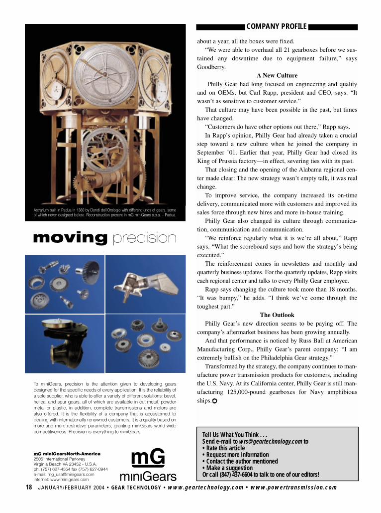
Astrarium built in Padua in 1360 by Dondi dell’Orologio with different kinds of gears, someof which never designed before. Reconstruction present in mG miniGears s.p.a. – Padua.
To miniGears, precision is the attention given to developing gearsdesigned for the specific needs of every application. It is the reliability ofa sole supplier, who is able to offer a variety of different solutions: bevel,helical and spur gears, all of which are available in cut metal, powdermetal or plastic, in addition, complete transmissions and motors arealso offered. It is the flexibility of a company that is accustomed todealing with internationally renowned customers. It is a quality based onmore and more restrictive parameters, granting miniGears world-widecompetitiveness. Precision is everything to miniGears. Tell Us What You Think . . .
Send e-mail to [email protected] to• Rate this article• Request more information• Contact the author mentioned• Make a suggestionOr call (847) 437-6604 to talk to one of our editors!

VISITTODAY!
www.geartechnology.com
www.geartechnology.comThe Gear Industry Home Page™
USE THE BUYERS GUIDEGet information from the industry’s leading suppliers
• Gear Machines • Cutting Tools & Grinding Wheels • Software• Non-Gear Machinery • Gear Blanks & Raw Material • Lubricants• Inspection Equipment • Workholding & Toolholding • Heat Treating• Services • Gear Drives • Gears
VISIT Gear Technology ONLINEYour No. 1 source for gear-related information online
• Sign up for E-GT • Renew your subscription• Order back issues • Read the latest news• Try our interactive Q&A forums • Request info from our advertisers
Keep your
literature files
current!
GEAR AND GEARBOX DESIGNKISSsoft is a software tool for the design of machine elements such as gears, shafts,
bearings, bolts, splines and springs. The main features of KISSsoft were developed forgearbox design and analysis.
The software calculates most of the machine elements according to methods specifiedin the current versions of DIN, ISO and AGMA standards. If no standard is available, ele-ments are calculated based on well recognized and accepted literature, says StefanBeermann, marketing director for KISSsoft AG, located in Hombrechtikon, Switzerland.
In addition to calculating geometry, the software performs load rating calculationsagainst static and fatigue loads, and it includes a number of functions to help designersoptimize the parts.
One of the most powerful functions, Beermann says, is the software’s ability to iteratethrough a given set of parameters for spur or helical gears. This allows the software todetermine the geometrically possible solutions and rate them according to strength, stiff-ness, noise, weight or other functions.
KISSsoft was originally developed by Kissling & Co. AG, a Swiss gearbox manufactur-er, but development and sales are now being handled by KISSsoft AG, an independentengineering consultancy. “During the last 25 years, the software has been constantlyimproved, and more functionality is added every day,” Beermann says.
Beermann adds that one of the strengths of KISSsoft is that it has been developed bytrained and experienced mechanical engineers, helping “to ensure that the design engi-neer gets a practical tool for his daily work.”
In addition to KISSsoft, the company offers an add-on package called KISSsys, whichwas developed for the definition of complete systems such as gearboxes or complete pow-ertrains. With KISSsys, all parts—including gears, shafts, bearings and couplings—arelinked, and the strength and life analyses are performed simultaneously for all elements.
KISSsys presents a 3-D graphic of the current state of the system. The graphic presentation shows the geometric influence of every changein parameter. “This approach greatly accelerates the design process and results in a much more balanced design,” Beermann says.For more information:KISSsoft AG • Frauwis 1 • CH-8634 Hombrechtikon, Switzerland Phone: +41 (55) 264 20 30 • Fax: +41 (55) 264 20 33 • E-mail: [email protected] • Web: www.kisssoft.ch20 JANUARY/FEBRUARY 2004 • GEAR TECHNOLOGY • www.geartechnology.com • www.powertransmission.com
SOFTWARE BITS
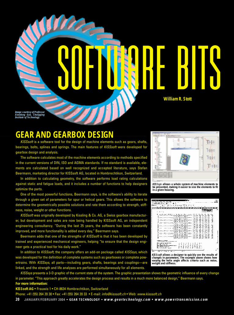
KISSsoft allows a designer to quickly see the results ofchanges in parameters. The example above shows howvarying the helix angle affects criteria such as noise,weight and stiffness.
KISSsys allows a whole system of machine elements tobe presented, making it easier to size the elements to fitin a given housing.
William R. Stott
Image courtesy of ProfessorXiaodong Guo, ChongqingInstitute of Technology.
www.powertransmission.com • www.geartechnology.com • GEAR TECHNOLOGY • JANUARY/FEBRUARY 2004 21
The Gear ProcessorHyGEARS version 2.0, “The Gear Processor”™ is a 3-D gear
modeling program for the design and development of hypoid, spiralbevel, straight bevel, spur, helical and face gears, as well as involutesplines.
HyGEARS allows the design, analysis and optimization of gearsets through functions such as tooth contact analysis (TCA) andloaded tooth contact analysis (LTCA). It supports the design anddevelopment of gears manufactured under Gleason’s FaceHobbing™, Fixed Setting™, Duplex Helical™, Modified Roll™,Spread Blade™, Formate™ and Helixform™ cutting processes.
The software was developed by Dr. Claude Gosselin of InvoluteSimulation Softwares Inc., located in Sillery, Quebec. According toGosselin, “The software has been extensively tested in industry.”
Blank geometry, cutter blade shape and machine settings canbe modified through the program’s “Summary Editor,” or those pa-rameters can be optimized through more advanced user-guidedfunctions.
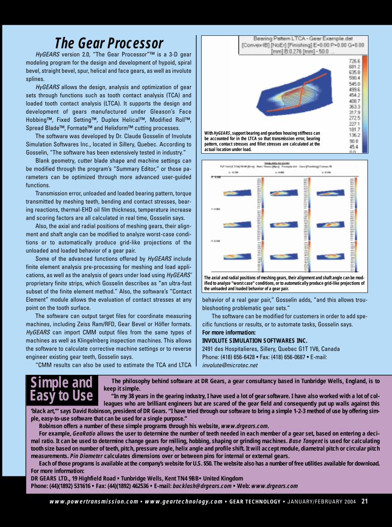
Transmission error, unloaded and loaded bearing pattern, torquetransmitted by meshing teeth, bending and contact stresses, bear-ing reactions, thermal-EHD oil film thickness, temperature increaseand scoring factors are all calculated in real time, Gosselin says.
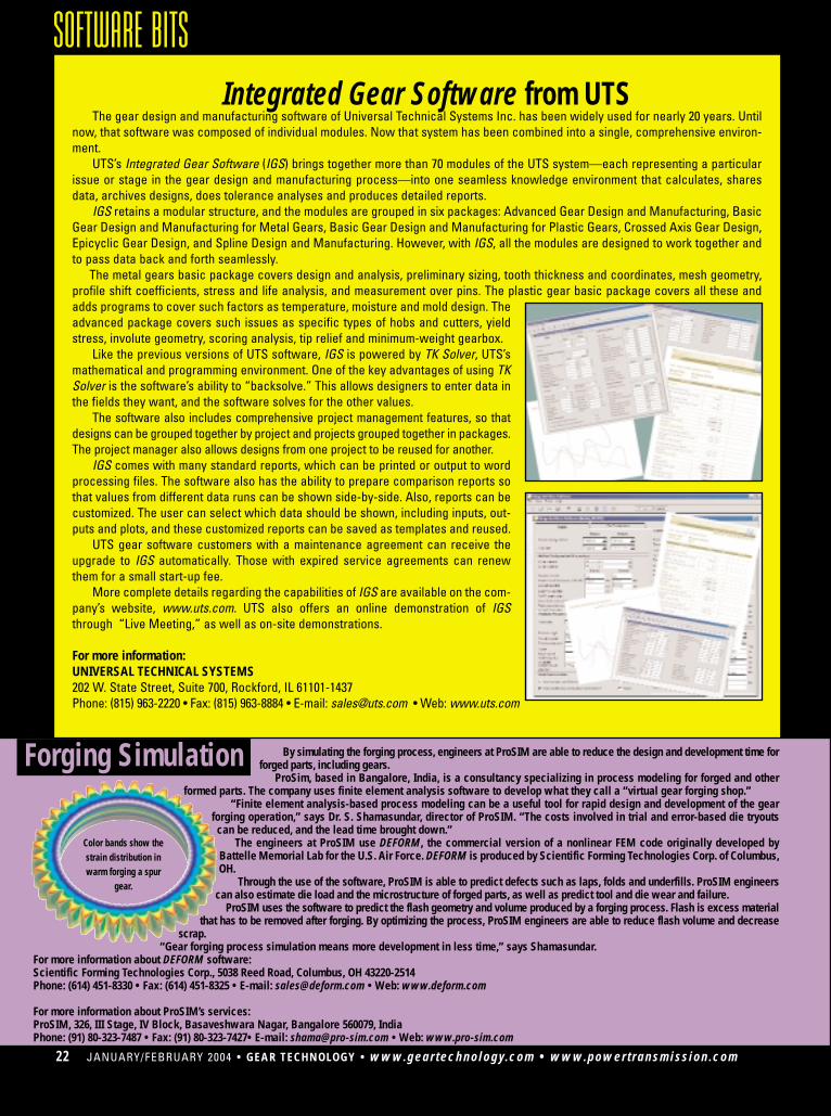
Also, the axial and radial positions of meshing gears, their align-ment and shaft angle can be modified to analyze worst-case condi-tions or to automatically produce grid-like projections of theunloaded and loaded behavior of a gear pair.
Some of the advanced functions offered by HyGEARS includefinite element analysis pre-processing for meshing and load appli-cations, as well as the analysis of gears under load using HyGEARS’proprietary finite strips, which Gosselin describes as “an ultra-fastsubset of the finite element method.” Also, the software’s “ContactElement” module allows the evaluation of contact stresses at anypoint on the tooth surface.
The software can output target files for coordinate measuringmachines, including Zeiss Ram/RFD, Gear Bevel or Höfler formats.HyGEARS can import CMM output files from the same types ofmachines as well as Klingelnberg inspection machines. This allowsthe software to calculate corrective machine settings or to reverseengineer existing gear teeth, Gosselin says.
“CMM results can also be used to estimate the TCA and LTCA
The axial and radial positions of meshing gears, their alignment and shaft angle can be mod-ified to analyze “worst case” conditions, or to automatically produce grid-like projections ofthe unloaded and loaded behavior of a gear pair.
The philosophy behind software at DR Gears, a gear consultancy based in Tunbridge Wells, England, is tokeep it simple.
“In my 38 years in the gearing industry, I have used a lot of gear software. I have also worked with a lot of col-leagues who are brilliant engineers but are scared of the gear field and consequently put up walls against this
‘black art,’” says David Robinson, president of DR Gears. “I have tried through our software to bring a simple 1-2-3 method of use by offering sim-ple, easy-to-use software that can be used for a single purpose.”
Robinson offers a number of these simple programs through his website, www.drgears.com.For example, GeaRatio allows the user to determine the number of teeth needed in each member of a gear set, based on entering a deci-
mal ratio. It can be used to determine change gears for milling, hobbing, shaping or grinding machines. Base Tangent is used for calculatingtooth size based on number of teeth, pitch, pressure angle, helix angle and profile shift. It will accept module, diametral pitch or circular pitchmeasurements. Pin Diameter calculates dimensions over or between pins for internal or external gears.
Each of those programs is available at the company’s website for U.S. $50. The website also has a number of free utilities available for download.For more information:DR GEARS LTD., 19 Highfield Road • Tunbridge Wells, Kent TN4 9BB• United KingdomPhone: (44)(1892) 531616 • Fax: (44)(1892) 462536 • E-mail: [email protected] • Web: www.drgears.com
Simple andEasy to Use
behavior of a real gear pair,” Gosselin adds, “and this allows trou-bleshooting problematic gear sets.”
The software can be modified for customers in order to add spe-cific functions or results, or to automate tasks, Gosselin says.For more information:INVOLUTE SIMULATION SOFTWARES INC.2491 des Hospitalieres, Sillery, Quebec G1T 1V6, CanadaPhone: (418) 656-6428 • Fax: (418) 656-0687 • E-mail:[email protected]
With HyGEARS, support bearing and gearbox housing stiffness canbe accounted for in the LTCA so that transmission error, bearingpattern, contact stresses and fillet stresses are calculated at theactual location under load.
00 JANUARY/FEBRUARY 2003 • GEAR TECHNOLOGY • www.geartechnology.com • www.powertransmission.com22 JANUARY/FEBRUARY 2004 • GEAR TECHNOLOGY • www.geartechnology.com • www.powertransmission.com
SOFTWARE BITSIntegrated Gear Software from UTS
The gear design and manufacturing software of Universal Technical Systems Inc. has been widely used for nearly 20 years. Untilnow, that software was composed of individual modules. Now that system has been combined into a single, comprehensive environ-ment.
UTS’s Integrated Gear Software (IGS) brings together more than 70 modules of the UTS system—each representing a particularissue or stage in the gear design and manufacturing process—into one seamless knowledge environment that calculates, sharesdata, archives designs, does tolerance analyses and produces detailed reports.
IGS retains a modular structure, and the modules are grouped in six packages: Advanced Gear Design and Manufacturing, BasicGear Design and Manufacturing for Metal Gears, Basic Gear Design and Manufacturing for Plastic Gears, Crossed Axis Gear Design,Epicyclic Gear Design, and Spline Design and Manufacturing. However, with IGS, all the modules are designed to work together andto pass data back and forth seamlessly.
The metal gears basic package covers design and analysis, preliminary sizing, tooth thickness and coordinates, mesh geometry,profile shift coefficients, stress and life analysis, and measurement over pins. The plastic gear basic package covers all these andadds programs to cover such factors as temperature, moisture and mold design. Theadvanced package covers such issues as specific types of hobs and cutters, yieldstress, involute geometry, scoring analysis, tip relief and minimum-weight gearbox.
Like the previous versions of UTS software, IGS is powered by TK Solver, UTS’smathematical and programming environment. One of the key advantages of using TKSolver is the software’s ability to “backsolve.” This allows designers to enter data inthe fields they want, and the software solves for the other values.
The software also includes comprehensive project management features, so thatdesigns can be grouped together by project and projects grouped together in packages.The project manager also allows designs from one project to be reused for another.
IGS comes with many standard reports, which can be printed or output to wordprocessing files. The software also has the ability to prepare comparison reports sothat values from different data runs can be shown side-by-side. Also, reports can becustomized. The user can select which data should be shown, including inputs, out-puts and plots, and these customized reports can be saved as templates and reused.
UTS gear software customers with a maintenance agreement can receive theupgrade to IGS automatically. Those with expired service agreements can renewthem for a small start-up fee.
More complete details regarding the capabilities of IGS are available on the com-pany’s website, www.uts.com. UTS also offers an online demonstration of IGSthrough “Live Meeting,” as well as on-site demonstrations.
For more information:UNIVERSAL TECHNICAL SYSTEMS202 W. State Street, Suite 700, Rockford, IL 61101-1437 Phone: (815) 963-2220 • Fax: (815) 963-8884 • E-mail: [email protected] • Web: www.uts.com
By simulating the forging process, engineers at ProSIM are able to reduce the design and development time forforged parts, including gears.
ProSim, based in Bangalore, India, is a consultancy specializing in process modeling for forged and otherformed parts. The company uses finite element analysis software to develop what they call a “virtual gear forging shop.”
“Finite element analysis-based process modeling can be a useful tool for rapid design and development of the gearforging operation,” says Dr. S. Shamasundar, director of ProSIM. “The costs involved in trial and error-based die tryouts
can be reduced, and the lead time brought down.”The engineers at ProSIM use DEFORM, the commercial version of a nonlinear FEM code originally developed by
Battelle Memorial Lab for the U.S. Air Force. DEFORM is produced by Scientific Forming Technologies Corp. of Columbus,OH.
Through the use of the software, ProSIM is able to predict defects such as laps, folds and underfills. ProSIM engineerscan also estimate die load and the microstructure of forged parts, as well as predict tool and die wear and failure.
ProSIM uses the software to predict the flash geometry and volume produced by a forging process. Flash is excess materialthat has to be removed after forging. By optimizing the process, ProSIM engineers are able to reduce flash volume and decrease
scrap.“Gear forging process simulation means more development in less time,” says Shamasundar.
For more information about DEFORM software:Scientific Forming Technologies Corp., 5038 Reed Road, Columbus, OH 43220-2514Phone: (614) 451-8330 • Fax: (614) 451-8325 • E-mail: [email protected] • Web: www.deform.com
For more information about ProSIM’s services:ProSIM, 326, III Stage, IV Block, Basaveshwara Nagar, Bangalore 560079, IndiaPhone: (91) 80-323-7487 • Fax: (91) 80-323-7427• E-mail: [email protected] • Web: www.pro-sim.com
Color bands show thestrain distribution inwarm forging a spur
gear.
Forging Simulation
www.powertransmission.com • www.geartechnology.com • GEAR TECHNOLOGY • JANUARY/FEBRUARY 2003 00www.powertransmission.com • www.geartechnology.com • GEAR TECHNOLOGY • JANUARY/FEBRUARY 2004 23
Parallel Axis Gear AnalysisPowerGear is a design and analysis tool for internal or external
spur, single helical and double helical gears. The software wasdeveloped by Ray Drago and Remco deJong of Drive SystemsTechnology Inc., located in Glen Mills, PA.
The software uses a prompted input sequence that allows it tocalculate gear tooth geometry, tool geometry, bending and con-tact stresses, flash temperature, strength and durability ratings inaccordance with AGMA 2001-C95, EHD film thickness, frictionalpower loss, scoring hazard rating, tooth profile kinematics, sub-surface shear stress/strength, required case depth for surfacehardened gears, and other calculations. PowerGear also pro-duces the manufacturing data needed to prepare an engineeringdrawing of a gear.
PowerGear can operate in conventional U.S. units or metricunits, and it can switch between the two. Users can directly entergeometry parameters themselves or use the software’s “paramet-ric mode” to allow the program to calculate the geometry for them.
A complementary module, DrawGear, is included withPowerGear. DrawGear allows gear mesh action to be vieweddynamically on screen. The gears rotate so that a visual indicationof mesh action can be observed.
The full professional version of PowerGear costs $695. A 30-day demo version can be downloaded at www.gear-doc.com.Also, a limited-capability student version of PowerGear is includ-ed in the cost of the “Applications in Parallel Axis Gear Design”seminars presented by Ray Drago at the University of Wisconsin-Milwaukee (visit www.uwm.edu/dept/ccee for information aboutthe seminars).
For more information:DRIVE SYSTEMS TECHNOLOGY INC.24 Marlborough LaneGlen Mills, PA 19342-1519Phone: (610) 358-0785Fax: (610) 358-2776E-mail: [email protected]: www.gear-doc.com
Animated CAD Solutionsfrom Trogetec
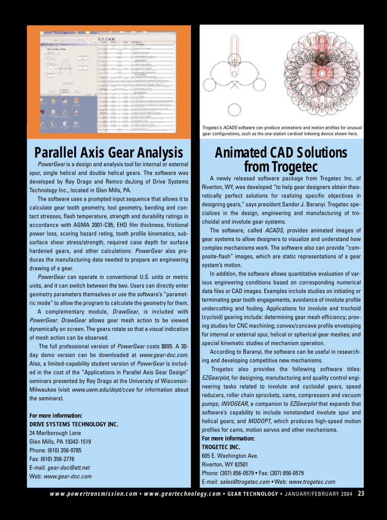
A newly released software package from Trogetec Inc. ofRiverton, WY, was developed “to help gear designers obtain theo-retically perfect solutions for realizing specific objectives indesigning gears,” says president Sandor J. Baranyi. Trogetec spe-cializes in the design, engineering and manufacturing of tro-choidal and involute gear systems.
The software, called ACADS, provides animated images ofgear systems to allow designers to visualize and understand howcomplex mechanisms work. The software also can provide “com-posite-flash” images, which are static representations of a gearsystem’s motion.
In addition, the software allows quantitative evaluation of var-ious engineering conditions based on corresponding numericaldata files or CAD images. Examples include studies on initiating orterminating gear tooth engagements, avoidance of involute profileundercutting and fouling. Applications for involute and trochoid(cycloid) gearing include: determining gear mesh efficiency; prov-ing studies for CNC machining; convex/concave profile envelopingfor internal or external spur, helical or spherical gear meshes; andspecial kinematic studies of mechanism operation.
According to Baranyi, the software can be useful in research-ing and developing competitive new mechanisms.
Trogetec also provides the following software titles:EZGearplot, for designing, manufacturing and quality control engi-neering tasks related to involute and cycloidal gears, speedreducers, roller chain sprockets, cams, compressors and vacuumpumps; INVOGEAR, a companion to EZGearplot that expands thatsoftware’s capability to include nonstandard involute spur andhelical gears; and MODOPT, which produces high-speed motionprofiles for cams, motion servos and other mechanisms.For more information:TROGETEC INC.605 E. Washington Ave.Riverton, WY 82501Phone: (307) 856-0579 • Fax: (307) 856-0579E-mail: [email protected] • Web: www.trogetec.com
Trogetec’s ACADS software can produce animations and motion profiles for unusualgear configurations, such as the one-station cardioid indexing device shown here.
GearDesignPro is a new program for designing spur and heli-cal gears, published by Dontyne Systems of Newark, England. Thesoftware, which rates gears for contact and bending strengthaccording to ISO 6336, is intended for both novice and advancedusers.
Features of GearDesignPro include flash temperature calcula-tions, center distance optimization, tolerancing based on ISO 1328,measurement over balls, and partial DXF output.
The center distance optimization routine allows the designer todetermine the minimum center distance that still allows all safetyfactors to be above 1.0. The calculation is based on the input ofhelix angle, material properties and other geometry constraints.
One of the advanced features of the software is a “DesignWorkspace Search,” which allows the user to generate thou-sands of gear designs and analyze and compare them in minutes.Various parameters can be plotted against each other, enablingthe designer to select the optimum design for his or her require-ments.
GearDesignPro comes in three different versions: Basic,Standard and Advanced. The Advanced version costs £1,200(about $2,080) and includes all features and functions describedabove. The Standard version costs £800 (about $1,390) andexcludes the “Design Workspace Search.” The Basic versioncosts £200 (about $350) and excludes the “Design WorkspaceSearch” and the center distance optimization routine.
For more information:DONTYNE SYSTEMS59 Kelham RoadNewark, Notts NG24 1BUUnited KingdomPhone: (44) 1636-704343Fax: (44) 1636-704343E-mail: [email protected]: www.dontyne.co.uk
[dontyne1.jpg]Graphic displays of gear teeth automatically update followingchanges to geometry data. Also, the effects of tooth thinning or
Software for Gear HobbingGearOffice© is a Windows-based computer program for cal-
culating hobbing machine settings and for organizing gear setups,hobs, machines and hobbing projects.
The software was developed and written by GearOffice Inc. inconsultation with Yefim Kotlyar of Bodine Electric in Chicago, IL.GearOffice is available for sale through GearHelp LLC ofCincinnati, OH.
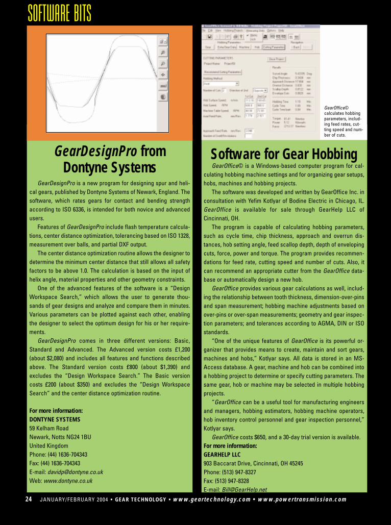
The program is capable of calculating hobbing parameters,such as cycle time, chip thickness, approach and overrun dis-tances, hob setting angle, feed scallop depth, depth of envelopingcuts, force, power and torque. The program provides recommen-dations for feed rate, cutting speed and number of cuts. Also, itcan recommend an appropriate cutter from the GearOffice data-base or automatically design a new hob.
GearOffice provides various gear calculations as well, includ-ing the relationship between tooth thickness, dimension-over-pinsand span measurement; hobbing machine adjustments based onover-pins or over-span measurements; geometry and gear inspec-tion parameters; and tolerances according to AGMA, DIN or ISOstandards.
“One of the unique features of GearOffice is its powerful or-ganizer that provides means to create, maintain and sort gears,machines and hobs,” Kotlyar says. All data is stored in an MS-Access database. A gear, machine and hob can be combined intoa hobbing project to determine or specify cutting parameters. Thesame gear, hob or machine may be selected in multiple hobbingprojects.
“GearOffice can be a useful tool for manufacturing engineersand managers, hobbing estimators, hobbing machine operators,hob inventory control personnel and gear inspection personnel,”Kotlyar says.
GearOffice costs $650, and a 30-day trial version is available.For more information:GEARHELP LLC903 Baccarat Drive, Cincinnati, OH 45245Phone: (513) 947-8327 Fax: (513) 947-8328E-mail: [email protected]
00 JANUARY/FEBRUARY 2003 • GEAR TECHNOLOGY • www.geartechnology.com • www.powertransmission.com24 JANUARY/FEBRUARY 2004 • GEAR TECHNOLOGY • www.geartechnology.com • www.powertransmission.com
SOFTWARE BITS
GearOffice©calculates hobbingparameters, includ-ing feed rates, cut-ting speed and num-ber of cuts.
GearDesignPro from Dontyne Systems
www.powertransmission.com • www.geartechnology.com • GEAR TECHNOLOGY • JANUARY/FEBRUARY 2003 00www.powertransmission.com • www.geartechnology.com • GEAR TECHNOLOGY • JANUARY/FEBRUARY 2004 25
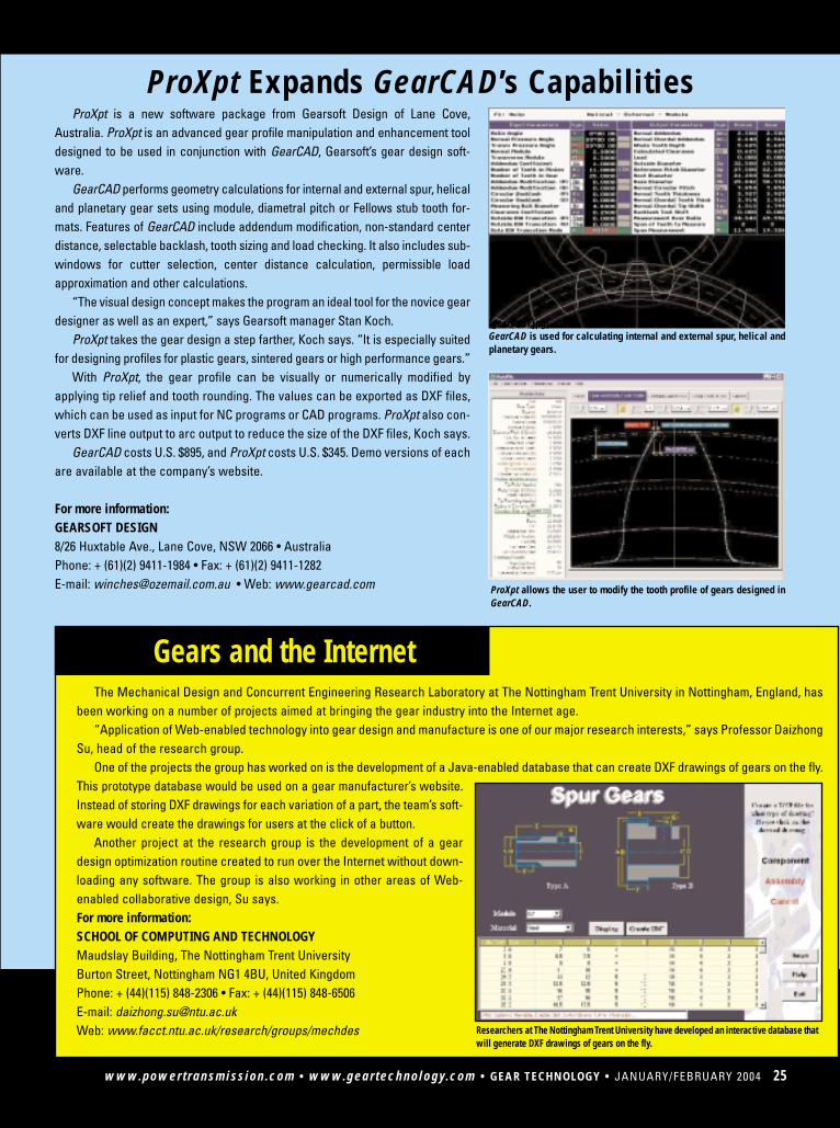
ProXpt is a new software package from Gearsoft Design of Lane Cove,Australia. ProXpt is an advanced gear profile manipulation and enhancement tooldesigned to be used in conjunction with GearCAD, Gearsoft’s gear design soft-ware.
GearCAD performs geometry calculations for internal and external spur, helicaland planetary gear sets using module, diametral pitch or Fellows stub tooth for-mats. Features of GearCAD include addendum modification, non-standard centerdistance, selectable backlash, tooth sizing and load checking. It also includes sub-windows for cutter selection, center distance calculation, permissible loadapproximation and other calculations.
“The visual design concept makes the program an ideal tool for the novice geardesigner as well as an expert,” says Gearsoft manager Stan Koch.
ProXpt takes the gear design a step farther, Koch says. “It is especially suitedfor designing profiles for plastic gears, sintered gears or high performance gears.”
With ProXpt, the gear profile can be visually or numerically modified byapplying tip relief and tooth rounding. The values can be exported as DXF files,which can be used as input for NC programs or CAD programs. ProXpt also con-verts DXF line output to arc output to reduce the size of the DXF files, Koch says.
GearCAD costs U.S. $895, and ProXpt costs U.S. $345. Demo versions of eachare available at the company’s website.
For more information:GEARSOFT DESIGN8/26 Huxtable Ave., Lane Cove, NSW 2066 • AustraliaPhone: + (61)(2) 9411-1984 • Fax: + (61)(2) 9411-1282E-mail: [email protected] • Web: www.gearcad.com
[gearcad1.jpg]GearCAD is used for calculating internal and external spur, helical andplanetary gears.
ProXpt Expands GearCAD’s Capabilities
The Mechanical Design and Concurrent Engineering Research Laboratory at The Nottingham Trent University in Nottingham, England, hasbeen working on a number of projects aimed at bringing the gear industry into the Internet age.
“Application of Web-enabled technology into gear design and manufacture is one of our major research interests,” says Professor DaizhongSu, head of the research group.
One of the projects the group has worked on is the development of a Java-enabled database that can create DXF drawings of gears on the fly.This prototype database would be used on a gear manufacturer’s website.Instead of storing DXF drawings for each variation of a part, the team’s soft-ware would create the drawings for users at the click of a button.
Another project at the research group is the development of a geardesign optimization routine created to run over the Internet without down-loading any software. The group is also working in other areas of Web-enabled collaborative design, Su says.For more information:SCHOOL OF COMPUTING AND TECHNOLOGYMaudslay Building, The Nottingham Trent UniversityBurton Street, Nottingham NG1 4BU, United KingdomPhone: + (44)(115) 848-2306 • Fax: + (44)(115) 848-6506E-mail: [email protected]: www.facct.ntu.ac.uk/research/groups/mechdes
Gears and the Internet
Researchers at The Nottingham Trent University have developed an interactive database thatwill generate DXF drawings of gears on the fly.
ProXpt allows the user to modify the tooth profile of gears designed inGearCAD.
00 JANUARY/FEBRUARY 2003 • GEAR TECHNOLOGY • www.geartechnology.com • www.powertransmission.com26 JANUARY/FEBRUARY 2004 • GEAR TECHNOLOGY • www.geartechnology.com • www.powertransmission.com
SOFTWARE BITS
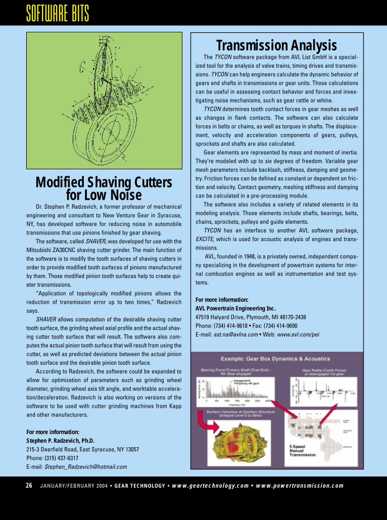
Modified Shaving Cuttersfor Low Noise
Dr. Stephen P. Radzevich, a former professor of mechanicalengineering and consultant to New Venture Gear in Syracuse,NY, has developed software for reducing noise in automobiletransmissions that use pinions finished by gear shaving.
The software, called SHAVER, was developed for use with theMitsubishi ZA30CNC shaving cutter grinder. The main function ofthe software is to modify the tooth surfaces of shaving cutters inorder to provide modified tooth surfaces of pinions manufacturedby them. Those modified pinion tooth surfaces help to create qui-eter transmissions.
“Application of topologically modified pinions allows thereduction of transmission error up to two times,” Radzevichsays.
SHAVER allows computation of the desirable shaving cuttertooth surface, the grinding wheel axial profile and the actual shav-ing cutter tooth surface that will result. The software also com-putes the actual pinion tooth surface that will result from using thecutter, as well as predicted deviations between the actual piniontooth surface and the desirable pinion tooth surface.
According to Radzevich, the software could be expanded toallow for optimization of parameters such as grinding wheeldiameter, grinding wheel axis tilt angle, and worktable accelera-tion/deceleration. Radzevich is also working on versions of thesoftware to be used with cutter grinding machines from Kappand other manufacturers.
For more information:Stephen P. Radzevich, Ph.D.215-3 Deerfield Road, East Syracuse, NY 13057Phone: (315) 437-6317E-mail: [email protected]
Transmission AnalysisThe TYCON software package from AVL List GmbH is a special-
ized tool for the analysis of valve trains, timing drives and transmis-sions. TYCON can help engineers calculate the dynamic behavior ofgears and shafts in transmissions or gear units. Those calculationscan be useful in assessing contact behavior and forces and inves-tigating noise mechanisms, such as gear rattle or whine.
TYCON determines tooth contact forces in gear meshes as wellas changes in flank contacts. The software can also calculateforces in belts or chains, as well as torques in shafts. The displace-ment, velocity and acceleration components of gears, pulleys,sprockets and shafts are also calculated.
Gear elements are represented by mass and moment of inertia.They’re modeled with up to six degrees of freedom. Variable gearmesh parameters include backlash, stiffness, damping and geome-try. Friction forces can be defined as constant or dependent on fric-tion and velocity. Contact geometry, meshing stiffness and dampingcan be calculated in a pre-processing module.
The software also includes a variety of related elements in itsmodeling analysis. Those elements include shafts, bearings, belts,chains, sprockets, pulleys and guide elements.
TYCON has an interface to another AVL software package,EXCITE, which is used for acoustic analysis of engines and trans-missions.
AVL, founded in 1948, is a privately owned, independent compa-ny specializing in the development of powertrain systems for inter-nal combustion engines as well as instrumentation and test sys-tems.
For more information:AVL Powertrain Engineering Inc.47519 Halyard Drive, Plymouth, MI 48170-2438Phone: (734) 414-9618 • Fax: (734) 414-9690E-mail: [email protected] • Web: www.avl.com/pei
www.powertransmission.com • www.geartechnology.com • GEAR TECHNOLOGY • JANUARY/FEBRUARY 2003 00
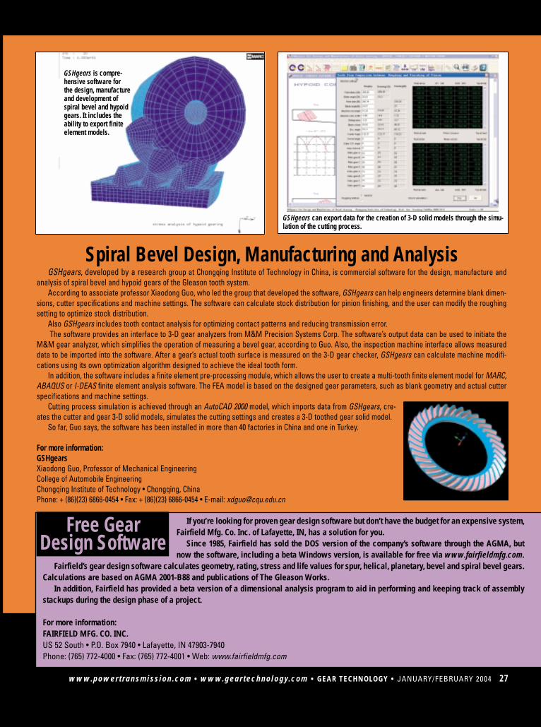
GSHgears can export data for the creation of 3-D solid models through the simu-lation of the cutting process.
GSHgears is compre-hensive software forthe design, manufactureand development of spiral bevel and hypoidgears. It includes theability to export finiteelement models.
Spiral Bevel Design, Manufacturing and Analysis
If you’re looking for proven gear design software but don’t have the budget for an expensive system,Fairfield Mfg. Co. Inc. of Lafayette, IN, has a solution for you.
Since 1985, Fairfield has sold the DOS version of the company’s software through the AGMA, butnow the software, including a beta Windows version, is available for free via www.fairfieldmfg.com.
Fairfield’s gear design software calculates geometry, rating, stress and life values for spur, helical, planetary, bevel and spiral bevel gears.Calculations are based on AGMA 2001-B88 and publications of The Gleason Works.
In addition, Fairfield has provided a beta version of a dimensional analysis program to aid in performing and keeping track of assemblystackups during the design phase of a project.
For more information:FAIRFIELD MFG. CO. INC.US 52 South • P.O. Box 7940 • Lafayette, IN 47903-7940Phone: (765) 772-4000 • Fax: (765) 772-4001 • Web: www.fairfieldmfg.com
Free Gear Design Software
GSHgears, developed by a research group at Chongqing Institute of Technology in China, is commercial software for the design, manufacture andanalysis of spiral bevel and hypoid gears of the Gleason tooth system.
According to associate professor Xiaodong Guo, who led the group that developed the software, GSHgears can help engineers determine blank dimen-sions, cutter specifications and machine settings. The software can calculate stock distribution for pinion finishing, and the user can modify the roughingsetting to optimize stock distribution.
Also GSHgears includes tooth contact analysis for optimizing contact patterns and reducing transmission error. The software provides an interface to 3-D gear analyzers from M&M Precision Systems Corp. The software’s output data can be used to initiate the
M&M gear analyzer, which simplifies the operation of measuring a bevel gear, according to Guo. Also, the inspection machine interface allows measureddata to be imported into the software. After a gear’s actual tooth surface is measured on the 3-D gear checker, GSHgears can calculate machine modifi-cations using its own optimization algorithm designed to achieve the ideal tooth form.
In addition, the software includes a finite element pre-processing module, which allows the user to create a multi-tooth finite element model for MARC,ABAQUS or I-DEAS finite element analysis software. The FEA model is based on the designed gear parameters, such as blank geometry and actual cutterspecifications and machine settings.
Cutting process simulation is achieved through an AutoCAD 2000 model, which imports data from GSHgears, cre-ates the cutter and gear 3-D solid models, simulates the cutting settings and creates a 3-D toothed gear solid model.
So far, Guo says, the software has been installed in more than 40 factories in China and one in Turkey.
For more information:GSHgearsXiaodong Guo, Professor of Mechanical EngineeringCollege of Automobile EngineeringChongqing Institute of Technology • Chongqing, ChinaPhone: + (86)(23) 6866-0454 • Fax: + (86)(23) 6866-0454 • E-mail: [email protected]
www.powertransmission.com • www.geartechnology.com • GEAR TECHNOLOGY • JANUARY/FEBRUARY 2004 27
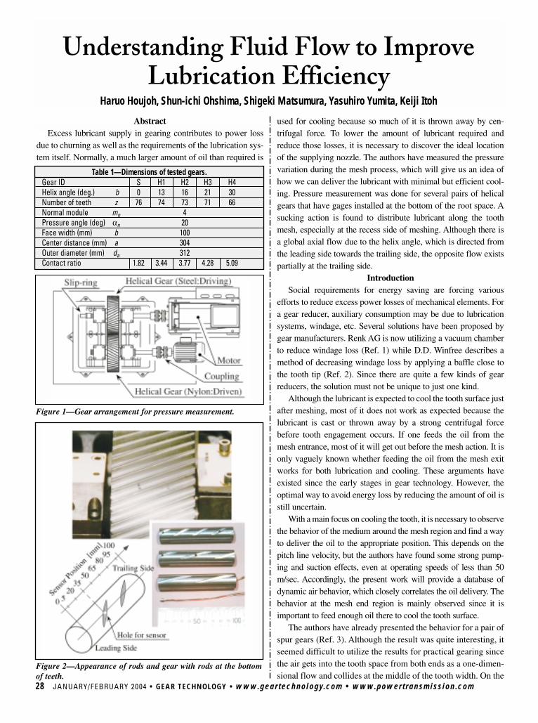
AbstractExcess lubricant supply in gearing contributes to power loss
due to churning as well as the requirements of the lubrication sys-tem itself. Normally, a much larger amount of oil than required is
Understanding Fluid Flow to ImproveLubrication Efficiency
Haruo Houjoh, Shun-ichi Ohshima, Shigeki Matsumura, Yasuhiro Yumita, Keiji Itoh
28 JANUARY/FEBRUARY 2004 • GEAR TECHNOLOGY • www.geartechnology.com • www.powertransmission.com
Figure 1—Gear arrangement for pressure measurement.
Table 1—Dimensions of tested gears.Gear ID S H1 H2 H3 H4Helix angle (deg.) b 0 13 16 21 30Number of teeth z 76 74 73 71 66Normal module mn 4Pressure angle (deg) αn 20Face width (mm) b 100Center distance (mm) a 304Outer diameter (mm) da 312Contact ratio 1.82 3.44 3.77 4.28 5.09
Figure 2—Appearance of rods and gear with rods at the bottomof teeth.
used for cooling because so much of it is thrown away by cen-trifugal force. To lower the amount of lubricant required andreduce those losses, it is necessary to discover the ideal locationof the supplying nozzle. The authors have measured the pressurevariation during the mesh process, which will give us an idea ofhow we can deliver the lubricant with minimal but efficient cool-ing. Pressure measurement was done for several pairs of helicalgears that have gages installed at the bottom of the root space. Asucking action is found to distribute lubricant along the toothmesh, especially at the recess side of meshing. Although there isa global axial flow due to the helix angle, which is directed fromthe leading side towards the trailing side, the opposite flow existspartially at the trailing side.
IntroductionSocial requirements for energy saving are forcing various
efforts to reduce excess power losses of mechanical elements. Fora gear reducer, auxiliary consumption may be due to lubricationsystems, windage, etc. Several solutions have been proposed bygear manufacturers. Renk AG is now utilizing a vacuum chamberto reduce windage loss (Ref. 1) while D.D. Winfree describes amethod of decreasing windage loss by applying a baffle close tothe tooth tip (Ref. 2). Since there are quite a few kinds of gearreducers, the solution must not be unique to just one kind.
Although the lubricant is expected to cool the tooth surface justafter meshing, most of it does not work as expected because thelubricant is cast or thrown away by a strong centrifugal forcebefore tooth engagement occurs. If one feeds the oil from themesh entrance, most of it will get out before the mesh action. It isonly vaguely known whether feeding the oil from the mesh exitworks for both lubrication and cooling. These arguments haveexisted since the early stages in gear technology. However, theoptimal way to avoid energy loss by reducing the amount of oil isstill uncertain.
With a main focus on cooling the tooth, it is necessary to observethe behavior of the medium around the mesh region and find a wayto deliver the oil to the appropriate position. This depends on thepitch line velocity, but the authors have found some strong pump-ing and suction effects, even at operating speeds of less than 50m/sec. Accordingly, the present work will provide a database ofdynamic air behavior, which closely correlates the oil delivery. Thebehavior at the mesh end region is mainly observed since it isimportant to feed enough oil there to cool the tooth surface.
The authors have already presented the behavior for a pair ofspur gears (Ref. 3). Although the result was quite interesting, itseemed difficult to utilize the results for practical gearing sincethe air gets into the tooth space from both ends as a one-dimen-sional flow and collides at the middle of the tooth width. On the
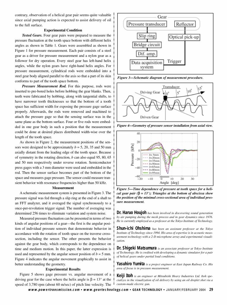
contrary, observation of a helical gear pair seems quite valuablesince axial pumping action is expected to assist delivery of oilto the full surface.
Experimental ConditionTested Gears. Four gear pairs were prepared to measure the
pressure fluctuation at the tooth space bottom with different helixangles as shown in Table 1. Gears were assembled as shown inFigure 1 for pressure measurement. Each pair consists of a steelgear as a driver for pressure measurement and a nylon gear as afollower for dry operation. Every steel gear has left-hand helixangles, while the nylon gears have right-hand helix angles. Forpressure measurement, cylindrical rods were embedded into asteel gear body aligned parallel to the axis so that a part of its skinconforms to part of the tooth space bottom.
Pressure Measurement Rod. For this purpose, rods wereinserted to pre-bored holes before hobbing the gear blanks. Then,teeth were fabricated by hobbing, along with tangential shifts, tohave narrower tooth thicknesses so that the bottom of a toothspace has sufficient width for exposing the pressure gage surfaceproperly. Afterwards, the rods were removed and machined toattach the pressure gage so that the sensing surface was in thesame plane as the bottom surface. Four or five rods were embed-ded in one gear body in such a position that the measurementcould be done at desired places distributed width-wise over thelength of the tooth space.
As shown in Figure 2, the measurement positions of the sen-sors were designed to be approximately b = 5, 20, 35 and 50 mmaxially distant from the leading edge of the tooth space. Becauseof symmetry in the rotating direction, b can also equal 95, 80, 65and 50 mm respectively under reverse rotation. Semiconductorpress gages with a 3 mm diameter were used and embedded in therod. Then the sensor surface becomes part of the bottom of thespace and measures gage pressure. The sensor could measure tran-sient behavior with resonance frequencies higher than 50 kHz.
MeasurementA schematic measurement system is presented in Figure 3. The
pressure signal was fed through a slip ring at the end of a shaft toan FFT analyzer, and it averaged the signal synchronously to aonce-per-revolution trigger signal. The number of averaging wasdetermined 256 times to eliminate variation and system noise.
Measured pressure fluctuation can be presented in terms of twokinds of angular positions of a gear—the first is the angular posi-tion of individual pressure sensors that demonstrate behavior inaccordance with the rotation of tooth space on the traverse cross-section, including the sensor. The other presents the behavioragainst the gear body, which corresponds to the dependence ontime and medium motion. In this paper, the latter expression isused and represented by the angular sensor position of b = 5 mm.Figure 4 indicates the angular movement graphically to assist inbetter understanding the geometry.
Experimental ResultsFigure 5 shows gage pressure vs. angular movement of a
driving gear for the case where the helix angle is β = 13° at thespeed of 3,780 rpm (about 60 m/sec) of pitch line velocity. The
Dr. Haruo Houjoh has been involved in discovering sound generationby air pumping during the mesh process and in gear dynamics since 1976.He is currently employed as a professor at the Tokyo Institute of Technology.
Shun-ichi Ohshima has been an assistant professor at the TokyoInstitute of Technology since 1994. His area of expertise is in acoustic meas-urement technology with a 2-D microphone array and experimental visuali-zation.
Dr. Shigeki Matsumura is an associate professor at Tokyo Instituteof Technology. He is credited with developing a dynamic simulator for a pairof helical gears under partial load conditions.
Yasuhiro Yumita is a project engineer at East Japan Railway Co. Hisarea of focus is in pressure measurement.
Keiji Itoh is an engineer at Mitsubishi Heavy Industries Ltd. Itoh spe-cializes in the visualization of oil delivery by using an oil droplet shot via acustom-made electric gun.
www.powertransmission.com • www.geartechnology.com • GEAR TECHNOLOGY • JANUARY/FEBRUARY 2004 29
Figure 3—Schematic diagram of measurement procedure.
Figure 4—Geometry of pressure sensor installation from axial view.
Figure 5—Time dependence of pressure at tooth space for a heli-cal gear pair (ββ = 13°); Triangles at the bottom of abscissa showthe position of the minimal cross-sectional area of individual pres-sure measurement.
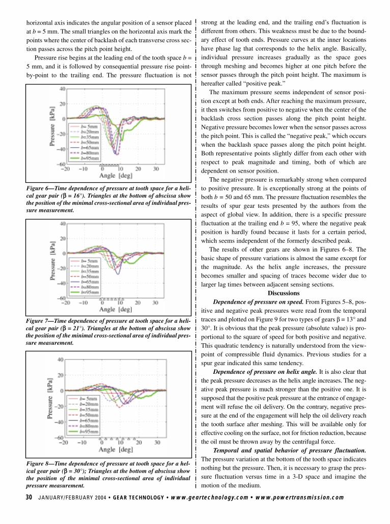
30 JANUARY/FEBRUARY 2004 • GEAR TECHNOLOGY • www.geartechnology.com • www.powertransmission.com
strong at the leading end, and the trailing end’s fluctuation isdifferent from others. This weakness must be due to the bound-ary effect of tooth ends. Pressure curves at the inner locationshave phase lag that corresponds to the helix angle. Basically,individual pressure increases gradually as the space goesthrough meshing and becomes higher at one pitch before thesensor passes through the pitch point height. The maximum ishereafter called “positive peak.”
The maximum pressure seems independent of sensor posi-tion except at both ends. After reaching the maximum pressure,it then switches from positive to negative when the center of thebacklash cross section passes along the pitch point height.Negative pressure becomes lower when the sensor passes acrossthe pitch point. This is called the “negative peak,” which occurswhen the backlash space passes along the pitch point height.Both representative points slightly differ from each other withrespect to peak magnitude and timing, both of which aredependent on sensor position.
The negative pressure is remarkably strong when comparedto positive pressure. It is exceptionally strong at the points ofboth b = 50 and 65 mm. The pressure fluctuation resembles theresults of spur gear tests presented by the authors from theaspect of global view. In addition, there is a specific pressurefluctuation at the trailing end b = 95, where the negative peakposition is hardly found because it lasts for a certain period,which seems independent of the formerly described peak.
The results of other gears are shown in Figures 6–8. Thebasic shape of pressure variations is almost the same except forthe magnitude. As the helix angle increases, the pressurebecomes smaller and spacing of traces become wider due tolarger lag times between adjacent sensing sections.
DiscussionsDependence of pressure on speed. From Figures 5–8, pos-
itive and negative peak pressures were read from the temporaltraces and plotted on Figure 9 for two types of gears β = 13° and30°. It is obvious that the peak pressure (absolute value) is pro-portional to the square of speed for both positive and negative.This quadratic tendency is naturally understood from the view-point of compressible fluid dynamics. Previous studies for aspur gear indicated this same tendency.
Dependence of pressure on helix angle. It is also clear thatthe peak pressure decreases as the helix angle increases. The neg-ative peak pressure is much stronger than the positive one. It issupposed that the positive peak pressure at the entrance of engage-ment will refuse the oil delivery. On the contrary, negative pres-sure at the end of the engagement will help the oil delivery reachthe tooth surface after meshing. This will be available only foreffective cooling on the surface, not for friction reduction, becausethe oil must be thrown away by the centrifugal force.
Temporal and spatial behavior of pressure fluctuation.The pressure variation at the bottom of the tooth space indicatesnothing but the pressure. Then, it is necessary to grasp the pres-sure fluctuation versus time in a 3-D space and imagine themotion of the medium.
Figure 6—Time dependence of pressure at tooth space for a heli-cal gear pair (ββ = 16°). Triangles at the bottom of abscissa showthe position of the minimal cross-sectional area of individual pres-sure measurement.
Figure 7—Time dependence of pressure at tooth space for a heli-cal gear pair (ββ = 21°). Triangles at the bottom of abscissa showthe position of the minimal cross-sectional area of individual pres-sure measurement.
horizontal axis indicates the angular position of a sensor placedat b = 5 mm. The small triangles on the horizontal axis mark thepoints where the center of backlash of each transverse cross sec-tion passes across the pitch point height.
Pressure rise begins at the leading end of the tooth space b =5 mm, and it is followed by consequential pressure rise point-by-point to the trailing end. The pressure fluctuation is not
Figure 8—Time dependence of pressure at tooth space for a hel-ical gear pair (ββ = 30°); Triangles at the bottom of abscissa showthe position of the minimal cross-sectional area of individualpressure measurement.
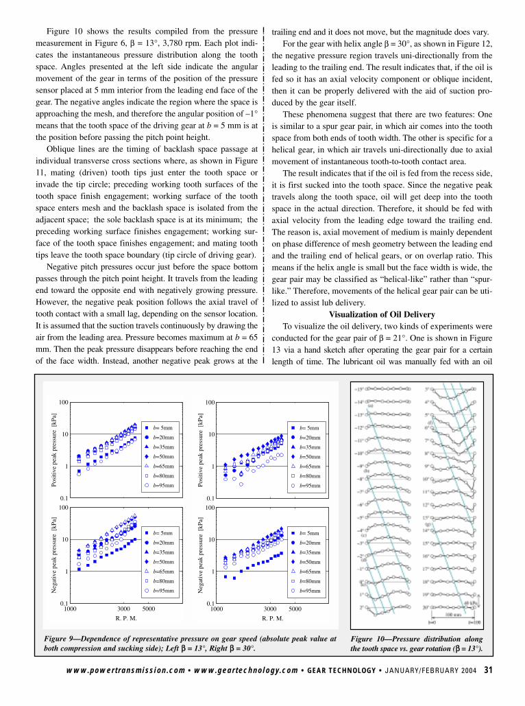
www.powertransmission.com • www.geartechnology.com • GEAR TECHNOLOGY • JANUARY/FEBRUARY 2004 31
Figure 10 shows the results compiled from the pressuremeasurement in Figure 6, β = 13°, 3,780 rpm. Each plot indi-cates the instantaneous pressure distribution along the toothspace. Angles presented at the left side indicate the angularmovement of the gear in terms of the position of the pressuresensor placed at 5 mm interior from the leading end face of thegear. The negative angles indicate the region where the space isapproaching the mesh, and therefore the angular position of –1°means that the tooth space of the driving gear at b = 5 mm is atthe position before passing the pitch point height.
Oblique lines are the timing of backlash space passage atindividual transverse cross sections where, as shown in Figure11, mating (driven) tooth tips just enter the tooth space orinvade the tip circle; preceding working tooth surfaces of thetooth space finish engagement; working surface of the toothspace enters mesh and the backlash space is isolated from theadjacent space; the sole backlash space is at its minimum; thepreceding working surface finishes engagement; working sur-face of the tooth space finishes engagement; and mating toothtips leave the tooth space boundary (tip circle of driving gear).
Negative pitch pressures occur just before the space bottompasses through the pitch point height. It travels from the leadingend toward the opposite end with negatively growing pressure.However, the negative peak position follows the axial travel oftooth contact with a small lag, depending on the sensor location.It is assumed that the suction travels continuously by drawing theair from the leading area. Pressure becomes maximum at b = 65mm. Then the peak pressure disappears before reaching the endof the face width. Instead, another negative peak grows at the
Figure 9—Dependence of representative pressure on gear speed (absolute peak value atboth compression and sucking side); Left ββ = 13°, Right ββ = 30°.
Figure 10—Pressure distribution alongthe tooth space vs. gear rotation (ββ = 13°).
0.1
1
10
100
b= 5mm
b=20mm
b=35mm
b=50mm
b=65mm
b=80mm
b=95mmPosi
tive
peak
pre
ssur
e [
kPa]
1000 3000 50000.1
1
10
100
b= 5mm
b=20mm
b=35mm
b=50mm
b=65mm
b=80mm
b=95mmNeg
ativ
e pe
ak p
ress
ure
[kP
a]
R. P. M.
0.1
1
10
100
b= 5mm
b=20mm
b=35mm
b=50mm
b=65mm
b=80mm
b=95mmPosi
tive
peak
pre
ssur
e [
kPa]
1000 3000 50000.1
1
10
100
b= 5mm
b=20mm
b=35mm
b=50mm
b=65mm
b=80mm
b=95mmNeg
ativ
e pe
ak p
ress
ure
[kP
a]
R. P. M.
trailing end and it does not move, but the magnitude does vary. For the gear with helix angle β = 30°, as shown in Figure 12,
the negative pressure region travels uni-directionally from theleading to the trailing end. The result indicates that, if the oil isfed so it has an axial velocity component or oblique incident,then it can be properly delivered with the aid of suction pro-duced by the gear itself.
These phenomena suggest that there are two features: Oneis similar to a spur gear pair, in which air comes into the toothspace from both ends of tooth width. The other is specific for ahelical gear, in which air travels uni-directionally due to axialmovement of instantaneous tooth-to-tooth contact area.
The result indicates that if the oil is fed from the recess side,it is first sucked into the tooth space. Since the negative peaktravels along the tooth space, oil will get deep into the toothspace in the actual direction. Therefore, it should be fed withaxial velocity from the leading edge toward the trailing end.The reason is, axial movement of medium is mainly dependenton phase difference of mesh geometry between the leading endand the trailing end of helical gears, or on overlap ratio. Thismeans if the helix angle is small but the face width is wide, thegear pair may be classified as “helical-like” rather than “spur-like.” Therefore, movements of the helical gear pair can be uti-lized to assist lub delivery.
Visualization of Oil DeliveryTo visualize the oil delivery, two kinds of experiments were
conducted for the gear pair of β = 21°. One is shown in Figure13 via a hand sketch after operating the gear pair for a certainlength of time. The lubricant oil was manually fed with an oil
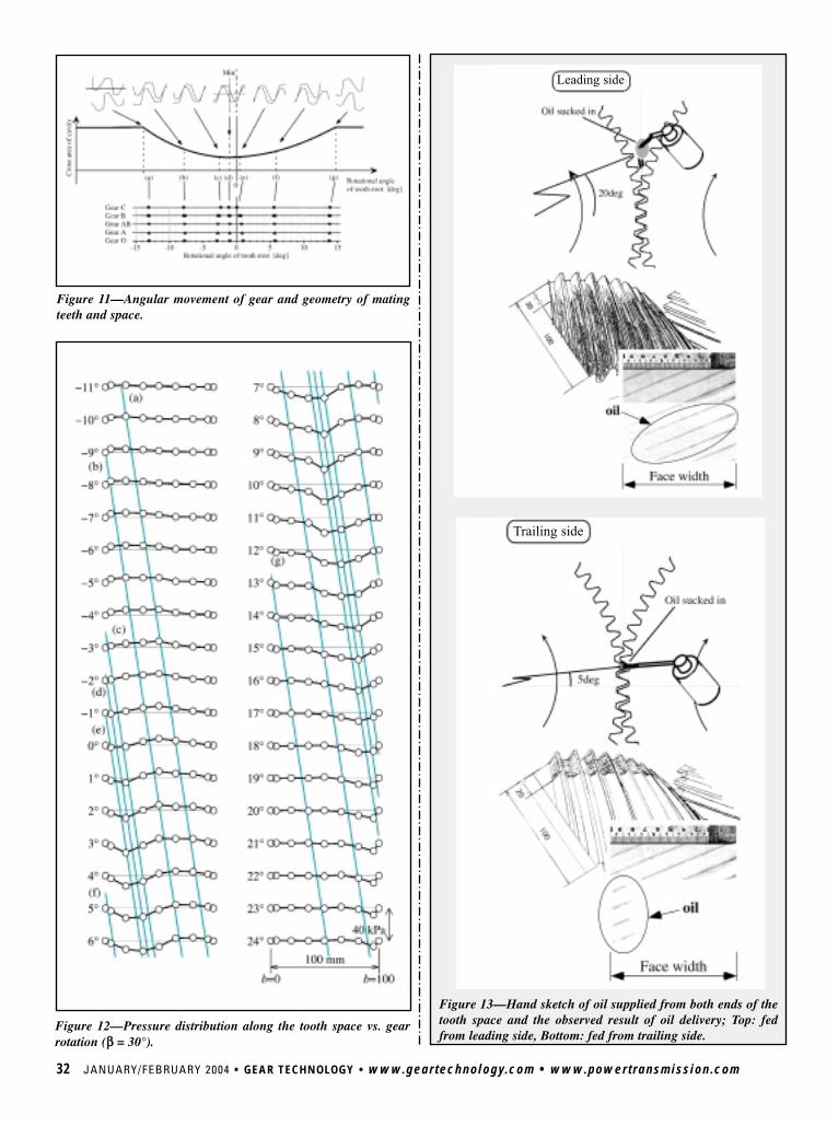
32 JANUARY/FEBRUARY 2004 • GEAR TECHNOLOGY • www.geartechnology.com • www.powertransmission.com
Figure 11—Angular movement of gear and geometry of matingteeth and space.
Figure 12—Pressure distribution along the tooth space vs. gearrotation (ββ = 30°).
Figure 13—Hand sketch of oil supplied from both ends of thetooth space and the observed result of oil delivery; Top: fedfrom leading side, Bottom: fed from trailing side.
Trailing side
Leading side
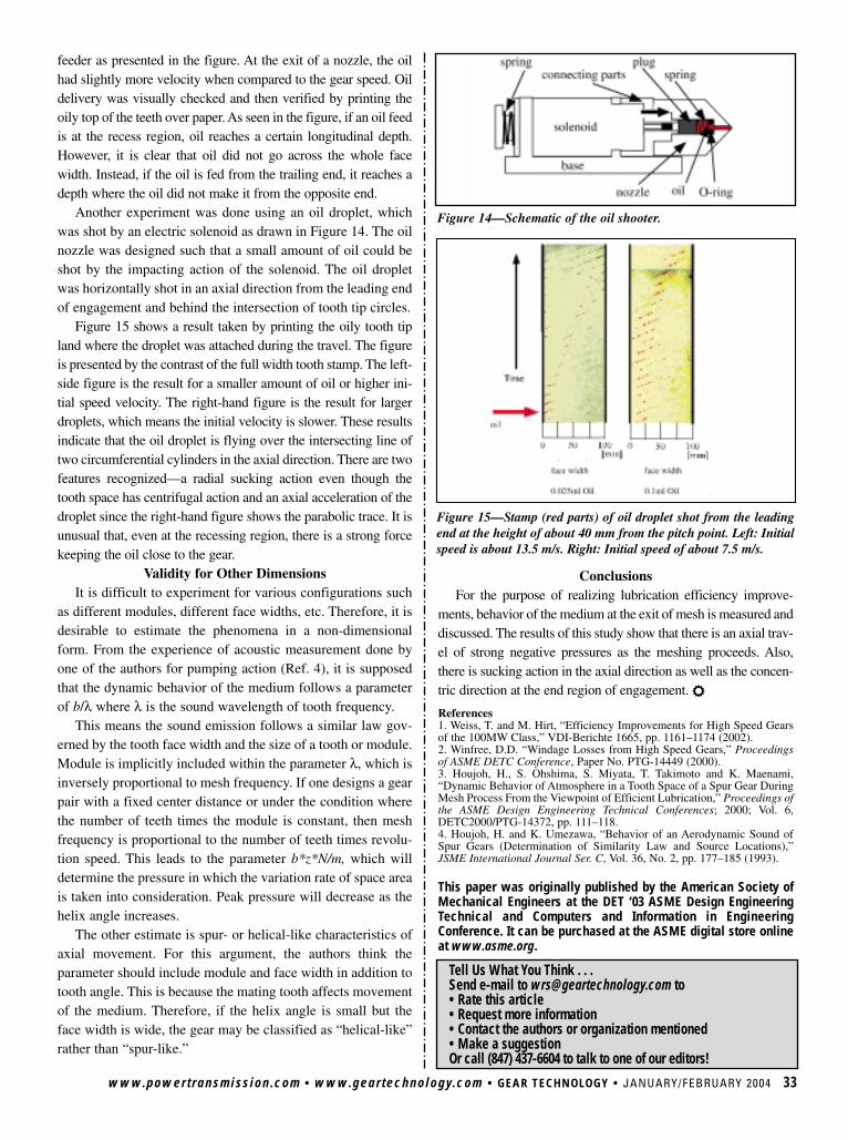
www.powertransmission.com • www.geartechnology.com • GEAR TECHNOLOGY • JANUARY/FEBRUARY 2004 33
Tell Us What You Think . . . Send e-mail to [email protected] to• Rate this article• Request more information• Contact the authors or organization mentioned• Make a suggestionOr call (847) 437-6604 to talk to one of our editors!
feeder as presented in the figure. At the exit of a nozzle, the oilhad slightly more velocity when compared to the gear speed. Oildelivery was visually checked and then verified by printing theoily top of the teeth over paper. As seen in the figure, if an oil feedis at the recess region, oil reaches a certain longitudinal depth.However, it is clear that oil did not go across the whole facewidth. Instead, if the oil is fed from the trailing end, it reaches adepth where the oil did not make it from the opposite end.
Another experiment was done using an oil droplet, whichwas shot by an electric solenoid as drawn in Figure 14. The oilnozzle was designed such that a small amount of oil could beshot by the impacting action of the solenoid. The oil dropletwas horizontally shot in an axial direction from the leading endof engagement and behind the intersection of tooth tip circles.
Figure 15 shows a result taken by printing the oily tooth tipland where the droplet was attached during the travel. The figureis presented by the contrast of the full width tooth stamp. The left-side figure is the result for a smaller amount of oil or higher ini-tial speed velocity. The right-hand figure is the result for largerdroplets, which means the initial velocity is slower. These resultsindicate that the oil droplet is flying over the intersecting line oftwo circumferential cylinders in the axial direction. There are twofeatures recognized—a radial sucking action even though thetooth space has centrifugal action and an axial acceleration of thedroplet since the right-hand figure shows the parabolic trace. It isunusual that, even at the recessing region, there is a strong forcekeeping the oil close to the gear.
Validity for Other DimensionsIt is difficult to experiment for various configurations such
as different modules, different face widths, etc. Therefore, it isdesirable to estimate the phenomena in a non-dimensionalform. From the experience of acoustic measurement done byone of the authors for pumping action (Ref. 4), it is supposedthat the dynamic behavior of the medium follows a parameterof b/λ where λ is the sound wavelength of tooth frequency.
This means the sound emission follows a similar law gov-erned by the tooth face width and the size of a tooth or module.Module is implicitly included within the parameter λ, which isinversely proportional to mesh frequency. If one designs a gearpair with a fixed center distance or under the condition wherethe number of teeth times the module is constant, then meshfrequency is proportional to the number of teeth times revolu-tion speed. This leads to the parameter b*z*N/m, which willdetermine the pressure in which the variation rate of space areais taken into consideration. Peak pressure will decrease as thehelix angle increases.
The other estimate is spur- or helical-like characteristics ofaxial movement. For this argument, the authors think theparameter should include module and face width in addition totooth angle. This is because the mating tooth affects movementof the medium. Therefore, if the helix angle is small but theface width is wide, the gear may be classified as “helical-like”rather than “spur-like.”
Figure 15—Stamp (red parts) of oil droplet shot from the leadingend at the height of about 40 mm from the pitch point. Left: Initialspeed is about 13.5 m/s. Right: Initial speed of about 7.5 m/s.
Figure 14—Schematic of the oil shooter.
ConclusionsFor the purpose of realizing lubrication efficiency improve-
ments, behavior of the medium at the exit of mesh is measured anddiscussed. The results of this study show that there is an axial trav-el of strong negative pressures as the meshing proceeds. Also,there is sucking action in the axial direction as well as the concen-tric direction at the end region of engagement. r
References1. Weiss, T. and M. Hirt, “Efficiency Improvements for High Speed Gearsof the 100MW Class,” VDI-Berichte 1665, pp. 1161–1174 (2002).2. Winfree, D.D. “Windage Losses from High Speed Gears,” Proceedingsof ASME DETC Conference, Paper No. PTG-14449 (2000).3. Houjoh, H., S. Ohshima, S. Miyata, T. Takimoto and K. Maenami,“Dynamic Behavior of Atmosphere in a Tooth Space of a Spur Gear DuringMesh Process From the Viewpoint of Efficient Lubrication,” Proceedings ofthe ASME Design Engineering Technical Conferences; 2000; Vol. 6,DETC2000/PTG-14372, pp. 111–118.4. Houjoh, H. and K. Umezawa, “Behavior of an Aerodynamic Sound ofSpur Gears (Determination of Similarity Law and Source Locations),”JSME International Journal Ser. C, Vol. 36, No. 2, pp. 177–185 (1993).
This paper was originally published by the American Society ofMechanical Engineers at the DET ‘03 ASME Design EngineeringTechnical and Computers and Information in EngineeringConference. It can be purchased at the ASME digital store onlineat www.asme.org.
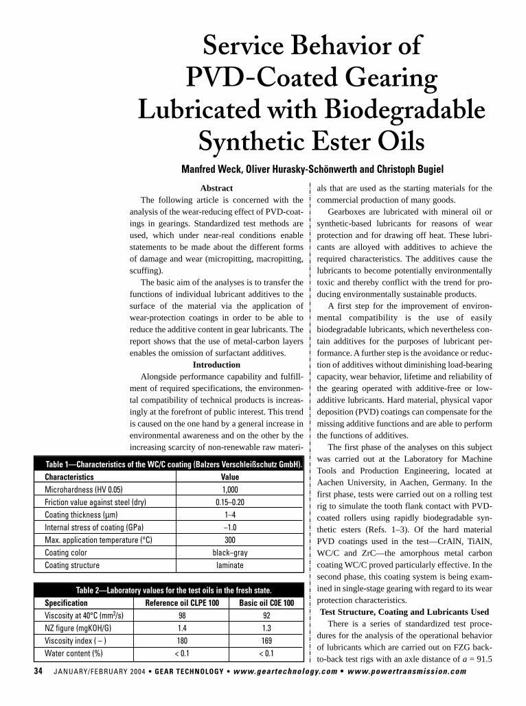
34 JANUARY/FEBRUARY 2004 • GEAR TECHNOLOGY • www.geartechnology.com • www.powertransmission.com
AbstractThe following article is concerned with the
analysis of the wear-reducing effect of PVD-coat-ings in gearings. Standardized test methods areused, which under near-real conditions enablestatements to be made about the different formsof damage and wear (micropitting, macropitting,scuffing).
The basic aim of the analyses is to transfer thefunctions of individual lubricant additives to thesurface of the material via the application ofwear-protection coatings in order to be able toreduce the additive content in gear lubricants. Thereport shows that the use of metal-carbon layersenables the omission of surfactant additives.
IntroductionAlongside performance capability and fulfill-
ment of required specifications, the environmen-tal compatibility of technical products is increas-ingly at the forefront of public interest. This trendis caused on the one hand by a general increase inenvironmental awareness and on the other by theincreasing scarcity of non-renewable raw materi-
als that are used as the starting materials for thecommercial production of many goods.
Gearboxes are lubricated with mineral oil orsynthetic-based lubricants for reasons of wearprotection and for drawing off heat. These lubri-cants are alloyed with additives to achieve therequired characteristics. The additives cause thelubricants to become potentially environmentallytoxic and thereby conflict with the trend for pro-ducing environmentally sustainable products.
A first step for the improvement of environ-mental compatibility is the use of easilybiodegradable lubricants, which nevertheless con-tain additives for the purposes of lubricant per-formance. A further step is the avoidance or reduc-tion of additives without diminishing load-bearingcapacity, wear behavior, lifetime and reliability ofthe gearing operated with additive-free or low-additive lubricants. Hard material, physical vapordeposition (PVD) coatings can compensate for themissing additive functions and are able to performthe functions of additives.
The first phase of the analyses on this subjectwas carried out at the Laboratory for MachineTools and Production Engineering, located atAachen University, in Aachen, Germany. In thefirst phase, tests were carried out on a rolling testrig to simulate the tooth flank contact with PVD-coated rollers using rapidly biodegradable syn-thetic esters (Refs. 1–3). Of the hard materialPVD coatings used in the test—CrAlN, TiAlN,WC/C and ZrC—the amorphous metal carboncoating WC/C proved particularly effective. In thesecond phase, this coating system is being exam-ined in single-stage gearing with regard to its wearprotection characteristics.Test Structure, Coating and Lubricants Used
There is a series of standardized test proce-dures for the analysis of the operational behaviorof lubricants which are carried out on FZG back-to-back test rigs with an axle distance of a = 91.5
Service Behavior of PVD-Coated Gearing
Lubricated with Biodegradable Synthetic Ester Oils
Manfred Weck, Oliver Hurasky-Schönwerth and Christoph Bugiel
Table 1—Characteristics of the WC/C coating (Balzers Verschleißschutz GmbH).Characteristics ValueMicrohardness (HV 0.05) 1,000Friction value against steel (dry) 0.15–0.20Coating thickness (µm) 1–4Internal stress of coating (GPa) –1.0Max. application temperature (°C) 300Coating color black–grayCoating structure laminate
Table 2—Laboratory values for the test oils in the fresh state.Specification Reference oil CLPE 100 Basic oil C0E 100Viscosity at 40°C (mm2/s) 98 92NZ figure (mgKOH/G) 1.4 1.3Viscosity index ( – ) 180 169Water content (%) < 0.1 < 0.1
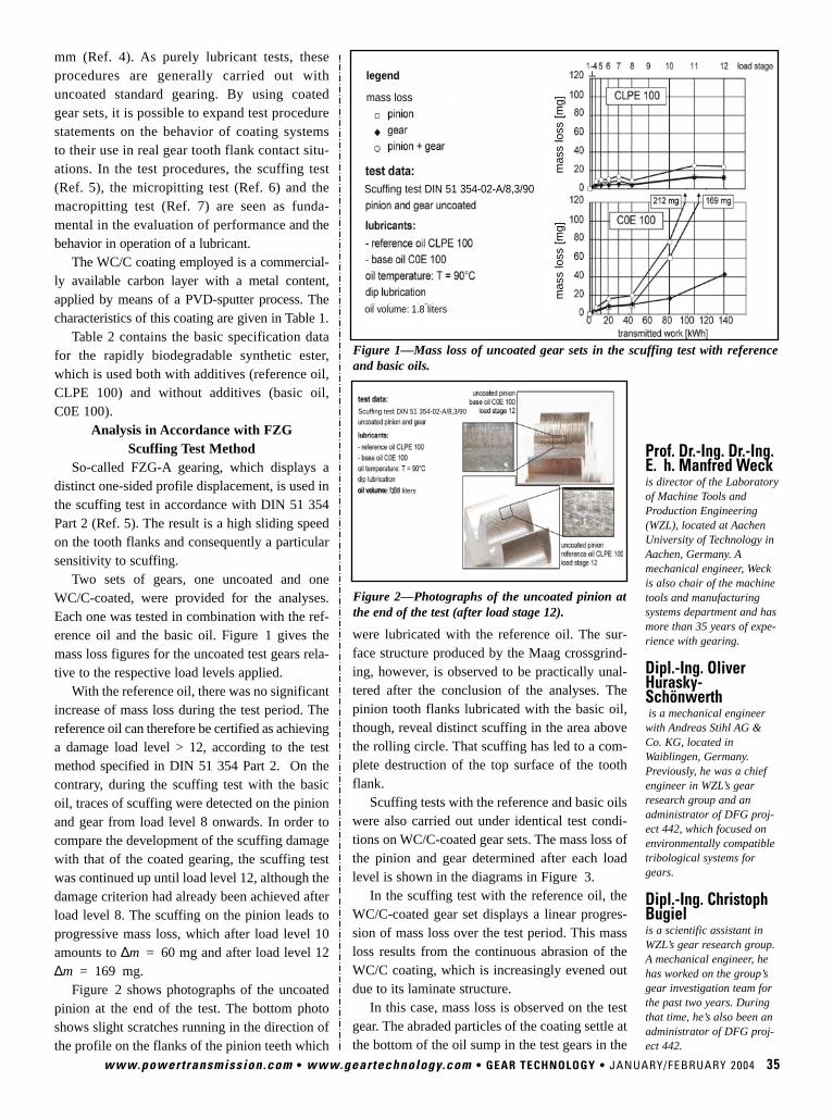
oil volume: 1.8 liters
mm (Ref. 4). As purely lubricant tests, theseprocedures are generally carried out withuncoated standard gearing. By using coatedgear sets, it is possible to expand test procedurestatements on the behavior of coating systemsto their use in real gear tooth flank contact situ-ations. In the test procedures, the scuffing test(Ref. 5), the micropitting test (Ref. 6) and themacropitting test (Ref. 7) are seen as funda-mental in the evaluation of performanceand thebehavior in operation of a lubricant.
The WC/C coating employed is a commercial-ly available carbon layer with a metal content,applied by means of a PVD-sputter process. Thecharacteristics of this coating are given in Table 1.
Table 2 contains the basic specification datafor the rapidly biodegradable synthetic ester,which is used both with additives (reference oil,CLPE 100) and without additives (basic oil,C0E 100).
Analysis in Accordance with FZG Scuffing Test Method
So-called FZG-A gearing, which displays adistinct one-sided profile displacement, is used inthe scuffing test in accordance with DIN 51 354Part 2 (Ref. 5). The result is a high sliding speedon the tooth flanks and consequently a particularsensitivity to scuffing.
Two sets of gears, one uncoated and oneWC/C-coated, were provided for the analyses.Each one was tested in combination with the ref-erence oil and the basic oil. Figure 1 gives themass loss figures for the uncoated test gears rela-tive to the respective load levels applied.
With the reference oil, there was no significantincrease of mass loss during the test period. Thereference oil can therefore be certified as achievinga damage load level > 12, according to the testmethod specified in DIN 51 354 Part 2. On thecontrary, during the scuffing test with the basicoil, traces of scuffing were detected on the pinionand gear from load level 8 onwards. In order tocompare the development of the scuffing damagewith that of the coated gearing, the scuffing testwas continued up until load level 12, although thedamage criterion had already been achieved afterload level 8. The scuffing on the pinion leads toprogressive mass loss, which after load level 10amounts to ∆m = 60 mg and after load level 12∆m = 169 mg.
Figure 2 shows photographs of the uncoatedpinion at the end of the test. The bottom photoshows slight scratches running in the direction ofthe profile on the flanks of the pinion teeth which
www.powertransmission.com • www.geartechnology.com • GEAR TECHNOLOGY • JANUARY/FEBRUARY 2004 35
were lubricated with the reference oil. The sur-face structure produced by the Maag crossgrind-ing, however, is observed to be practically unal-tered after the conclusion of the analyses. Thepinion tooth flanks lubricated with the basic oil,though, reveal distinct scuffing in the area abovethe rolling circle. That scuffing has led to a com-plete destruction of the top surface of the toothflank.
Scuffing tests with the reference and basic oilswere also carried out under identical test condi-tions on WC/C-coated gear sets. The mass loss ofthe pinion and gear determined after each loadlevel is shown in the diagrams in Figure 3.
In the scuffing test with the reference oil, theWC/C-coated gear set displays a linear progres-sion of mass loss over the test period. This massloss results from the continuous abrasion of theWC/C coating, which is increasingly evened outdue to its laminate structure.
In this case, mass loss is observed on the testgear. The abraded particles of the coating settle atthe bottom of the oil sump in the test gears in the
Prof. Dr.-Ing. Dr.-Ing.E. h. Manfred Weck is director of the Laboratoryof Machine Tools andProduction Engineering(WZL), located at AachenUniversity of Technology inAachen, Germany. Amechanical engineer, Weckis also chair of the machinetools and manufacturingsystems department and hasmore than 35 years of expe-rience with gearing.
Dipl.-Ing. OliverHurasky-Schönwerth is a mechanical engineerwith Andreas Stihl AG &Co. KG, located inWaiblingen, Germany.Previously, he was a chiefengineer in WZL’s gearresearch group and anadministrator of DFG proj-ect 442, which focused onenvironmentally compatibletribological systems forgears.
Dipl.-Ing. ChristophBugiel is a scientific assistant inWZL’s gear research group.A mechanical engineer, hehas worked on the group’sgear investigation team forthe past two years. Duringthat time, he’s also been anadministrator of DFG proj-ect 442.
Figure 1—Mass loss of uncoated gear sets in the scuffing test with referenceand basic oils.
Figure 2—Photographs of the uncoated pinion atthe end of the test (after load stage 12).
legend
mas
s lo
ss [
mg]
mas
s lo
ss [
mg]
mass loss
Scuffing test DIN 51 354-02-A/8,3/90
Scuffing test DIN 51 354-02-A/8,3/90
oil volume: 1.8 liters
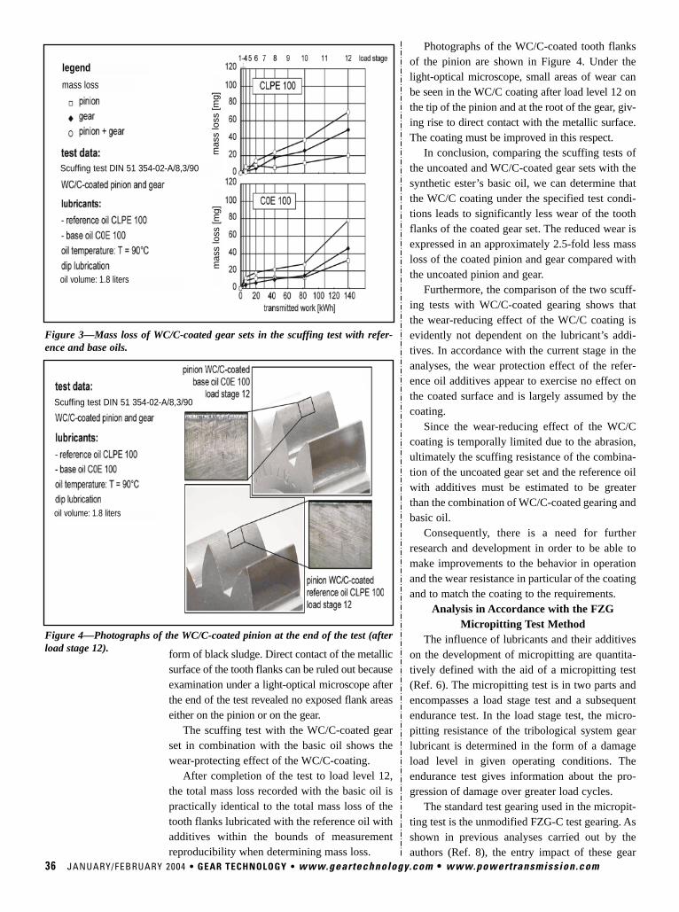
Photographs of the WC/C-coated tooth flanksof the pinion are shown in Figure 4. Under thelight-optical microscope, small areas of wear canbe seen in the WC/C coating after load level 12 onthe tip of the pinion and at the root of the gear, giv-ing rise to direct contact with the metallic surface.The coating must be improved in this respect.
In conclusion, comparing the scuffing tests ofthe uncoated and WC/C-coated gear sets with thesynthetic ester’s basic oil, we can determine thatthe WC/C coating under the specified test condi-tions leads to significantly less wear of the toothflanks of the coated gear set. The reduced wear isexpressed in an approximately 2.5-fold less massloss of the coated pinion and gear compared withthe uncoated pinion and gear.
Furthermore, the comparison of the two scuff-ing tests with WC/C-coated gearing shows thatthe wear-reducing effect of the WC/C coating isevidently not dependent on the lubricant’s addi-tives. In accordance with the current stage in theanalyses, the wear protection effect of the refer-ence oil additives appear to exercise no effect onthe coated surface and is largely assumed by thecoating.
Since the wear-reducing effect of the WC/Ccoating is temporally limited due to the abrasion,ultimately the scuffing resistance of the combina-tion of the uncoated gear set and the reference oilwith additives must be estimated to be greaterthan the combination of WC/C-coated gearing andbasic oil.
Consequently, there is a need for furtherresearch and development in order to be able tomake improvements to the behavior in operationand the wear resistance in particular of the coatingand to match the coating to the requirements.
Analysis in Accordance with the FZGMicropitting Test Method
The influence of lubricants and their additiveson the development of micropitting are quantita-tively defined with the aid of a micropitting test(Ref. 6). The micropitting test is in two parts andencompasses a load stage test and a subsequentendurance test. In the load stage test, the micro-pitting resistance of the tribological system gearlubricant is determined in the form of a damageload level in given operating conditions. Theendurance test gives information about the pro-gression of damage over greater load cycles.
The standard test gearing used in the micropit-ting test is the unmodified FZG-C test gearing. Asshown in previous analyses carried out by theauthors (Ref. 8), the entry impact of these gear
36 JANUARY/FEBRUARY 2004 • GEAR TECHNOLOGY • www.geartechnology.com • www.powertransmission.com
form of black sludge. Direct contact of the metallicsurface of the tooth flanks can be ruled out becauseexamination under a light-optical microscope afterthe end of the test revealed no exposed flank areaseither on the pinion or on the gear.
The scuffing test with the WC/C-coated gearset in combination with the basic oil shows thewear-protecting effect of the WC/C-coating.
After completion of the test to load level 12,the total mass loss recorded with the basic oil ispractically identical to the total mass loss of thetooth flanks lubricated with the reference oil withadditives within the bounds of measurementreproducibility when determining mass loss.
Figure 3—Mass loss of WC/C-coated gear sets in the scuffing test with refer-ence and base oils.
Figure 4—Photographs of the WC/C-coated pinion at the end of the test (afterload stage 12).
oil volume: 1.8 liters
legend
mas
s lo
ss [
mg]
mass loss
Scuffing test DIN 51 354-02-A/8,3/90
mas
s lo
ss [
mg]
Scuffing test DIN 51 354-02-A/8,3/90
oil volume: 1.8 liters
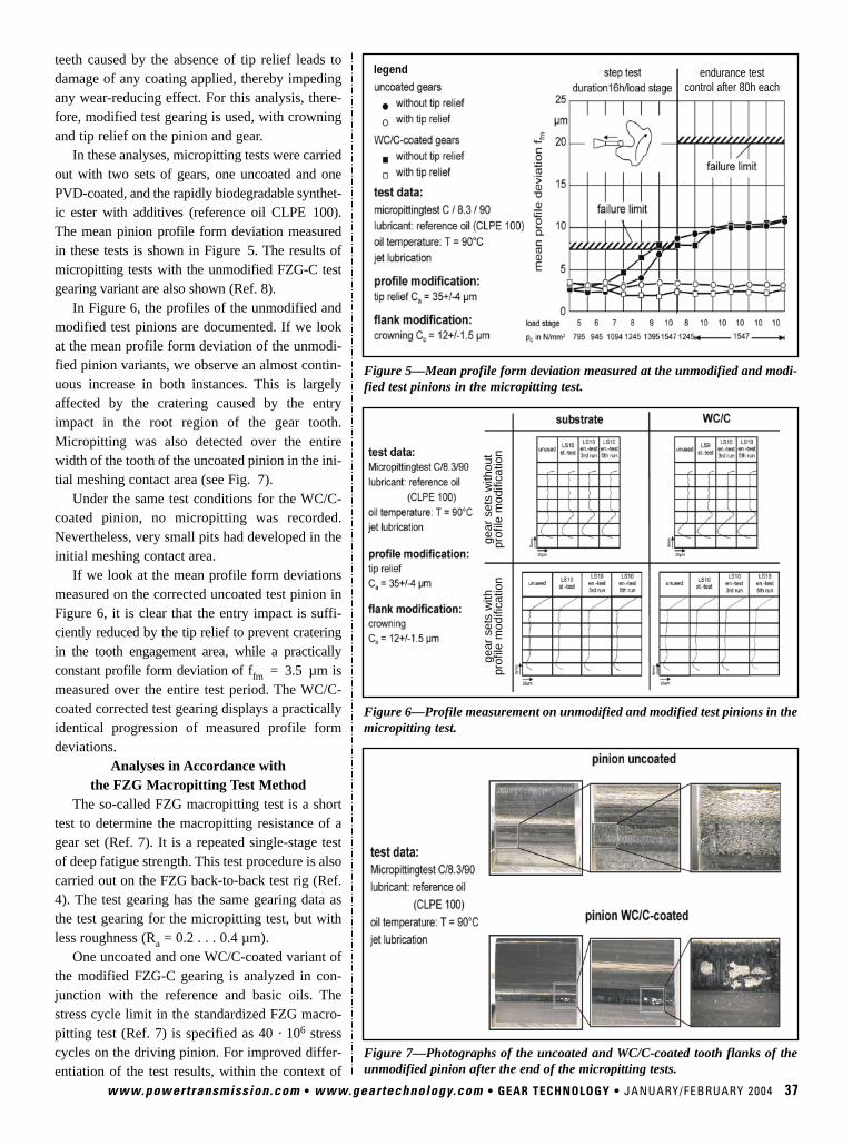
www.powertransmission.com • www.geartechnology.com • GEAR TECHNOLOGY • JANUARY/FEBRUARY 2004 37
teeth caused by the absence of tip relief leads todamage of any coating applied, thereby impedingany wear-reducing effect. For this analysis, there-fore, modified test gearing is used, with crowningand tip relief on the pinion and gear.
In these analyses, micropitting tests were carriedout with two sets of gears, one uncoated and onePVD-coated, and the rapidly biodegradable synthet-ic ester with additives (reference oil CLPE 100).The mean pinion profile form deviation measuredin these tests is shown in Figure 5. The results ofmicropitting tests with the unmodified FZG-C testgearing variant are also shown (Ref. 8).
In Figure 6, the profiles of the unmodified andmodified test pinions are documented. If we lookat the mean profile form deviation of the unmodi-fied pinion variants, we observe an almost contin-uous increase in both instances. This is largelyaffected by the cratering caused by the entryimpact in the root region of the gear tooth.Micropitting was also detected over the entirewidth of the tooth of the uncoated pinion in the ini-tial meshing contact area (see Fig. 7).
Under the same test conditions for the WC/C-coated pinion, no micropitting was recorded.Nevertheless, very small pits had developed in theinitial meshing contact area.
If we look at the mean profile form deviationsmeasured on the corrected uncoated test pinion inFigure 6, it is clear that the entry impact is suffi-ciently reduced by the tip relief to prevent crateringin the tooth engagement area, while a practicallyconstant profile form deviation of ffm = 3.5 µm ismeasured over the entire test period. The WC/C-coated corrected test gearing displays a practicallyidentical progression of measured profile formdeviations.
Analyses in Accordance with the FZG Macropitting Test Method
The so-called FZG macropitting test is a shorttest to determine the macropitting resistance of agear set (Ref. 7). It is a repeated single-stage testof deep fatigue strength. This test procedure is alsocarried out on the FZG back-to-back test rig (Ref.4). The test gearing has the same gearing data asthe test gearing for the micropitting test, but withless roughness (Ra = 0.2 . . . 0.4 µm).
One uncoated and one WC/C-coated variant ofthe modified FZG-C gearing is analyzed in con-junction with the reference and basic oils. Thestress cycle limit in the standardized FZG macro-pitting test (Ref. 7) is specified as 40 · 106 stresscycles on the driving pinion. For improved differ-entiation of the test results, within the context of
Figure 5—Mean profile form deviation measured at the unmodified and modi-fied test pinions in the micropitting test.
Figure 6—Profile measurement on unmodified and modified test pinions in themicropitting test.
Figure 7—Photographs of the uncoated and WC/C-coated tooth flanks of theunmodified pinion after the end of the micropitting tests.
legend
gear
set
s w
ithou
tpr
ofile
mod
ifica
tion
gear
set
s w
ith
prof
ile m
odifi
catio
n
endurance testcontrol after 80h each
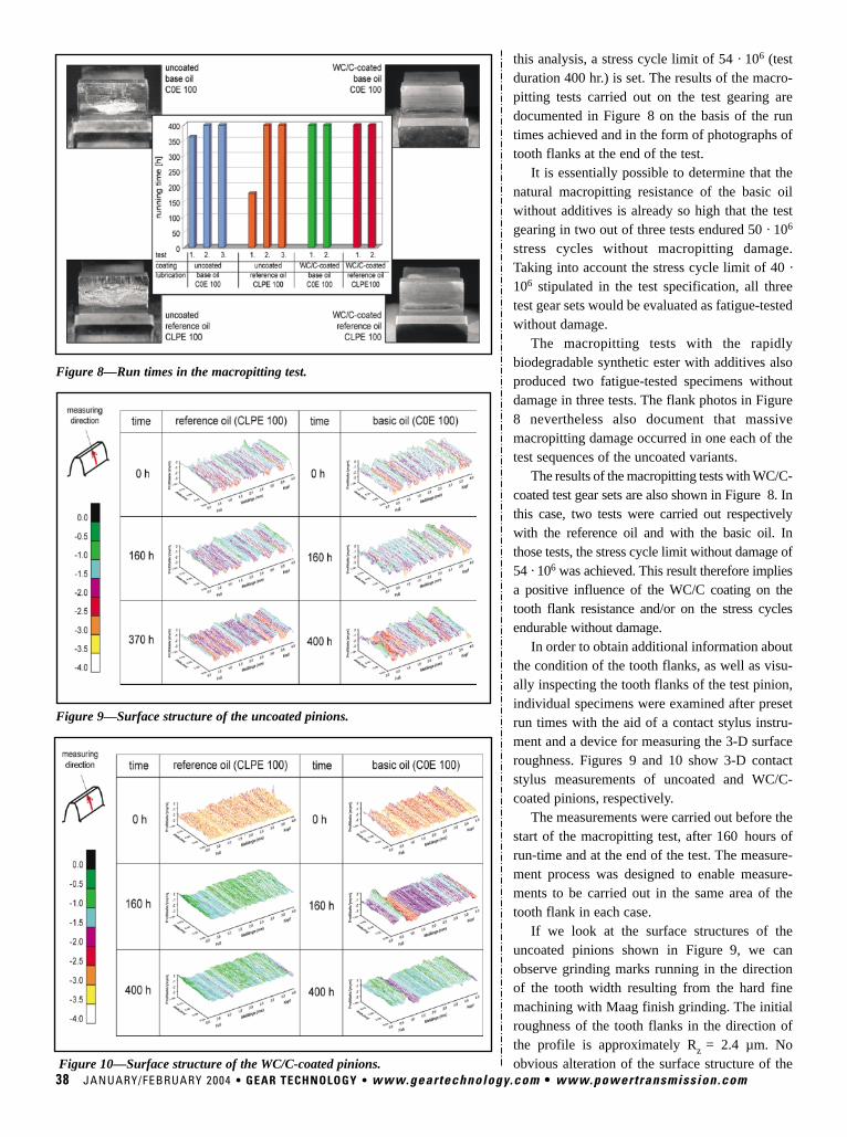
this analysis, a stress cycle limit of 54 · 106 (testduration 400 hr.) is set. The results of the macro-pitting tests carried out on the test gearing aredocumented in Figure 8 on the basis of the runtimes achieved and in the form of photographs oftooth flanks at the end of the test.
It is essentially possible to determine that thenatural macropitting resistance of the basic oilwithout additives is already so high that the testgearing in two out of three tests endured 50 · 106
stress cycles without macropitting damage.Taking into account the stress cycle limit of 40 ·106 stipulated in the test specification, all threetest gear sets would be evaluated as fatigue-testedwithout damage.
The macropitting tests with the rapidlybiodegradable synthetic ester with additives alsoproduced two fatigue-tested specimens withoutdamage in three tests. The flank photos in Figure8 nevertheless also document that massivemacropitting damage occurred in one each of thetest sequences of the uncoated variants.
The results of the macropitting tests with WC/C-coated test gear sets are also shown in Figure 8. Inthis case, two tests were carried out respectivelywith the reference oil and with the basic oil. Inthose tests, the stress cycle limit without damage of54 · 106 was achieved. This result therefore impliesa positive influence of the WC/C coating on thetooth flank resistance and/or on the stress cyclesendurable without damage.
In order to obtain additional information aboutthe condition of the tooth flanks, as well as visu-ally inspecting the tooth flanks of the test pinion,individual specimens were examined after presetrun times with the aid of a contact stylus instru-ment and a device for measuring the 3-D surfaceroughness. Figures 9 and 10 show 3-D contactstylus measurements of uncoated and WC/C-coated pinions, respectively.
The measurements were carried out before thestart of the macropitting test, after 160 hours ofrun-time and at the end of the test. The measure-ment process was designed to enable measure-ments to be carried out in the same area of thetooth flank in each case.
If we look at the surface structures of theuncoated pinions shown in Figure 9, we canobserve grinding marks running in the directionof the tooth width resulting from the hard finemachining with Maag finish grinding. The initialroughness of the tooth flanks in the direction ofthe profile is approximately Rz = 2.4 µm. Noobvious alteration of the surface structure of the
38 JANUARY/FEBRUARY 2004 • GEAR TECHNOLOGY • www.geartechnology.com • www.powertransmission.com
Figure 8—Run times in the macropitting test.
Figure 9—Surface structure of the uncoated pinions.
Figure 10—Surface structure of the WC/C-coated pinions.
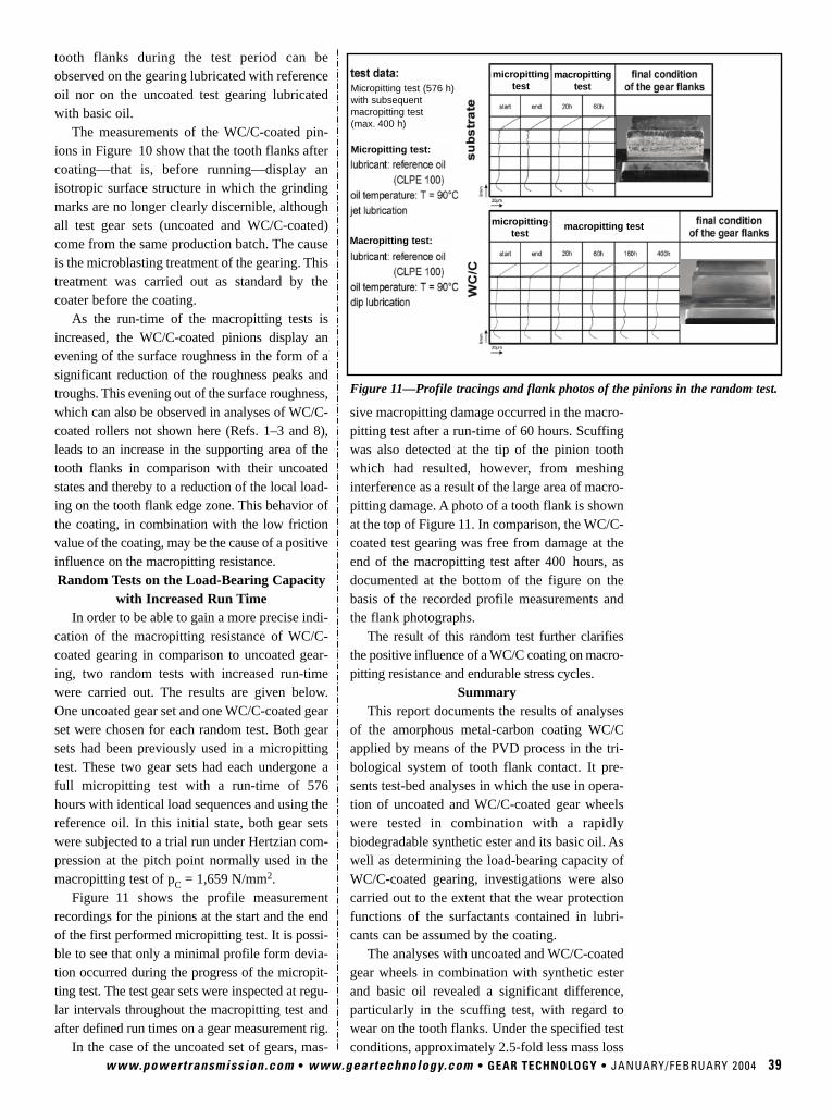
www.powertransmission.com • www.geartechnology.com • GEAR TECHNOLOGY • JANUARY/FEBRUARY 2004 39
tooth flanks during the test period can beobserved on the gearing lubricated with referenceoil nor on the uncoated test gearing lubricatedwith basic oil.
The measurements of the WC/C-coated pin-ions in Figure 10 show that the tooth flanks aftercoating—that is, before running—display anisotropic surface structure in which the grindingmarks are no longer clearly discernible, althoughall test gear sets (uncoated and WC/C-coated)come from the same production batch. The causeis the microblasting treatment of the gearing. Thistreatment was carried out as standard by thecoater before the coating.
As the run-time of the macropitting tests isincreased, the WC/C-coated pinions display anevening of the surface roughness in the form of asignificant reduction of the roughness peaks andtroughs. This evening out of the surface roughness,which can also be observed in analyses of WC/C-coated rollers not shown here (Refs. 1–3 and 8),leads to an increase in the supporting area of thetooth flanks in comparison with their uncoatedstates and thereby to a reduction of the local load-ing on the tooth flank edge zone. This behavior ofthe coating, in combination with the low frictionvalue of the coating, may be the cause of a positiveinfluence on the macropitting resistance.Random Tests on the Load-Bearing Capacity
with Increased Run TimeIn order to be able to gain a more precise indi-
cation of the macropitting resistance of WC/C-coated gearing in comparison to uncoated gear-ing, two random tests with increased run-timewere carried out. The results are given below.One uncoated gear set and one WC/C-coated gearset were chosen for each random test. Both gearsets had been previously used in a micropittingtest. These two gear sets had each undergone afull micropitting test with a run-time of 576hours with identical load sequences and using thereference oil. In this initial state, both gear setswere subjected to a trial run under Hertzian com-pression at the pitch point normally used in themacropitting test of pC = 1,659 N/mm2.
Figure 11 shows the profile measurementrecordings for the pinions at the start and the endof the first performed micropitting test. It is possi-ble to see that only a minimal profile form devia-tion occurred during the progress of the micropit-ting test. The test gear sets were inspected at regu-lar intervals throughout the macropitting test andafter defined run times on a gear measurement rig.
In the case of the uncoated set of gears, mas-
sive macropitting damage occurred in the macro-pitting test after a run-time of 60 hours. Scuffingwas also detected at the tip of the pinion toothwhich had resulted, however, from meshinginterference as a result of the large area of macro-pitting damage. A photo of a tooth flank is shownat the top of Figure 11. In comparison, the WC/C-coated test gearing was free from damage at theend of the macropitting test after 400 hours, asdocumented at the bottom of the figure on thebasis of the recorded profile measurements andthe flank photographs.
The result of this random test further clarifiesthe positive influence of a WC/C coating on macro-pitting resistance and endurable stress cycles.
SummaryThis report documents the results of analyses
of the amorphous metal-carbon coating WC/Capplied by means of the PVD process in the tri-bological system of tooth flank contact. It pre-sents test-bed analyses in which the use in opera-tion of uncoated and WC/C-coated gear wheelswere tested in combination with a rapidlybiodegradable synthetic ester and its basic oil. Aswell as determining the load-bearing capacity ofWC/C-coated gearing, investigations were alsocarried out to the extent that the wear protectionfunctions of the surfactants contained in lubri-cants can be assumed by the coating.
The analyses with uncoated and WC/C-coatedgear wheels in combination with synthetic esterand basic oil revealed a significant difference,particularly in the scuffing test, with regard towear on the tooth flanks. Under the specified testconditions, approximately 2.5-fold less mass loss
Figure 11—Profile tracings and flank photos of the pinions in the random test.
macropittingtest
macropitting testMacropitting test:
Micropitting test:
Micropitting test (576 h)with subsequentmacropitting test(max. 400 h)
micropittingtest
micropittingtest
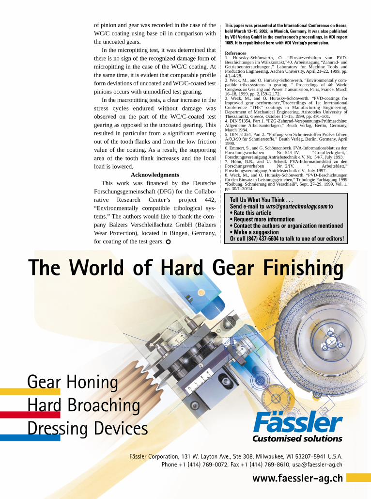
This paper was presented at the International Conference on Gears,held March 13–15, 2002, in Munich, Germany. It was also publishedby VDI Verlag GmbH in the conference’s proceedings, in VDI report1665. It is republished here with VDI Verlag’s permission.
References1. Hurasky-Schönwerth, O. “Einsatzverhalten von PVD-Beschichtungen im Wälzkontakt,”40. Arbeitstagung “Zahnrad- undGetriebeuntersuchungen,” Laboratory for Machine Tools andProduction Engineering, Aachen University, April 21–22, 1999, pp.4/1–4/28.2. Weck, M., and O. Hurasky-Schönwerth. “Environmentally com-patible tribo-systems in gearing, ” Proceedings of 4th WorldCongress on Gearing and Power Transmission, Paris, France, March16–18, 1999, pp. 2,159–2,172.3. Weck, M., and O. Hurasky-Schönwerth. “PVD-coatings forimproved gear performance,”Proceedings of 1st InternationalConference “THE” coatings in Manufacturing Engineering,Department of Mechanical Engineering, Aristoteles University ofThessaloniki, Greece, October 14–15, 1999, pp. 491–501.4. DIN 51354, Part 1. “FZG-Zahnrad-Verspannungs-Prüfmaschine:Allgemeine Arbeitsunterlagen,” Beuth Verlag, Berlin, Germany,March 1984.5. DIN 51354, Part 2. “Prüfung von Schmierstoffen PrüfverfahrenA/8,3/90 für Schmierstoffe,” Beuth Verlag, Berlin, Germany, April1990.6. Emmert, S., and G. Schönnenbeck. FVA-Informationsblatt zu denForschungsvorhaben Nr. 54/I-IV, “Graufleckigkeit,”Forschungsvereinigung Antriebstechnik e.V. Nr. 54/7, July 1993.7. Höhn, B.R., and U. Schedl. FVA-Informationsblatt zu denForschungsvorhaben Nr. 2/IV, “ Arbeitsblatt,”Forschungsvereinigung Antriebstechnik e.V., July 1997.8. Weck, M., and O. Hurasky-Schönwerth. “PVD-Beschichtungenfür den Einsatz in Leistungsgetrieben,” Tribologie Fachtagung 1999“Reibung, Schmierung und Verschleiß”, Sept. 27–29, 1999, Vol. 1,pp. 30/1–30/14.
of pinion and gear was recorded in the case of theWC/C coating using base oil in comparison withthe uncoated gears.
In the micropitting test, it was determined thatthere is no sign of the recognized damage form ofmicropitting in the case of the WC/C coating. Atthe same time, it is evident that comparable profileform deviations of uncoated and WC/C-coated testpinions occurs with unmodified test gearing.
In the macropitting tests, a clear increase in thestress cycles endured without damage wasobserved on the part of the WC/C-coated testgearing as opposed to the uncoated gearing. Thisresulted in particular from a significant eveningout of the tooth flanks and from the low frictionvalue of the coating. As a result, the supportingarea of the tooth flank increases and the localload is lowered.
AcknowledgmentsThis work was financed by the Deutsche
Forschungsgemeinschaft (DFG) for the Collabo-rative Research Center’s project 442,“Environmentally compatible tribological sys-tems.” The authors would like to thank the com-pany Balzers Verschleißschutz GmbH (BalzersWear Protection), located in Bingen, Germany,for coating of the test gears. r
Tell Us What You Think . . . Send e-mail to [email protected] to• Rate this article• Request more information• Contact the authors or organization mentioned• Make a suggestionOr call (847) 437-6604 to talk to one of our editors!
The World of Hard Gear Finishing
Fässler Corporation, 131 W. Layton Ave., Ste 308, Milwaukee, WI 53207-5941 U.S.A.Phone +1 (414) 769-0072, Fax +1 (414) 769-8610, [email protected]
www.faessler-ag.ch
Gear HoningHard BroachingDressing Devices

Tell Us What You Think . . . Send e-mail to [email protected] to• Rate this column• Request more information• Contact the organizations mentioned• Make a suggestionOr call (847) 437-6604 to talk to one of our editors!
TECHNICAL CALENDAR
January 13–15—14th Annual International Colloquium onTribology & Lubrication Engineering. Technische AkademieEsslingen, Stuttgart/Ostfildern, Germany. Topics include testingof lubricant properties, gear lubrication, friction and wear inextreme environments, coolants and basics of friction. Englishand German are the official languages of the show. 650€ or$748. For more information, contact the sponsors by telephoneat (49) 711-340-0823 or by e-mail at [email protected].
February 9–10—Introduction to ANSI/AGMA/AWEA 6006-A03, Standard for the Design and Specification of Gearboxesfor Wind Turbines. National Wind Technology Center, Golden,CO. Sponsored jointly by AGMA and the National RenewableEnergy Lab, this program will include presentations on the tech-nical requirement of AGMA’s 6006 standard from different per-spectives and introduce the new global wind turbine standard. Inaddition, attendees can take a tour of the NWTC dynamometerand NWTC test facilities. $320. For more information, contactthe AGMA by telephone at (703) 838-0052 or on the Internet atwww.agma.org.
February 23–25—National Design Engineering Show &Conference. McCormick Place Convention Center, Chicago, IL.Featuring the latest in the CAD/CAM, rapid prototyping and con-tract manufacturing industries. Registration is free before January26. For more information, contact Reed Exhibitions on theInternet at www.reedexhibitions.com.
February 26–29—BI-MU Mediterranea. Fiera Del Levante,Bari, Italy. For individuals in the machine tool, robotics andautomation industries. The main focus will be on systems basedon modular design, which can be adapted to production variables. The fee is 260€ or $299 to attend and 55€ or $64 forexhibitors. For more information, visit the event’s website atwww.bimu-mediterranea.it.
March 16—Heat Treating & Hardening of Gears. Holiday InnCity Center, Chicago, IL. Sponsored by the Society ofManufacturing Engineers, topics include specific microstructuresand mechanical results, performance successes, quality controlmethodologies, and guidelines for preferred procedures. $495 forSME members, $695 for non-members. For more information,contact the SME by telephone at (313) 425-3098 or on theInternet at www.sme.org.
www.powertransmission.com • www.geartechnology.com • GEAR TECHNOLOGY • JANUARY/FEBRUARY 2004 41
Since 1936 has provided the gear industrywith gear inspection devices. Put your trust in the
people who invented the pro c e s s.
1205 36th Avenue WestAlexandria, MN 56308 U.S.A.
Ph: (320) 762-8782Fax: (320) 762-5260
E-mail: [email protected]
. . . from the Source
A U T O M A T I CI N S P ECT I O N
Precision CheckingHeads
High Speed Automatic Functional Tester
For additional information on GearBurnishing and/or Functional Gear
Inspection, visit our website at:www.itwgears.com
FEATURES:• Composite Gaging• Composite/Center Distance Checks• Lead/Taper Checks• SPC Capabilities• Data Acquisition Screens
PRODUCTS AVAILABLE:• Fully Automatic Machines• Semi-Automatic Machines• Manual Double Flank Testers
for Course and Fine Pitch Gears• Dimension over Pins/Balls Gage
Automatic Functional GearInpection In-Line Gages
Proudly Manufacturedin the USA
GROUND GEARS – Ten or Ten ThousandFor small to medium quantities of spurs or helicals that have tomeet clost-tolerance AGMA or DIN specs, our Reishauer grindersand M&M gear analysis systems are the perfect combination.
For Long runs, we offer the unique Liebherr CBN grindingprocess with full SPC quality control and documentation.
So whether your needs are for ten or tens of thousands, weinvite you to join the growing list of INSCO customers who rely onus for consistent quality, reasonable costs, and reliable delivery.
PHONE: 978-448-6368FAX: 978-448-5155WEB: inscocorp.com
ISO 9001 Registered
412 Main Street, Groton, Massachusetts 01450
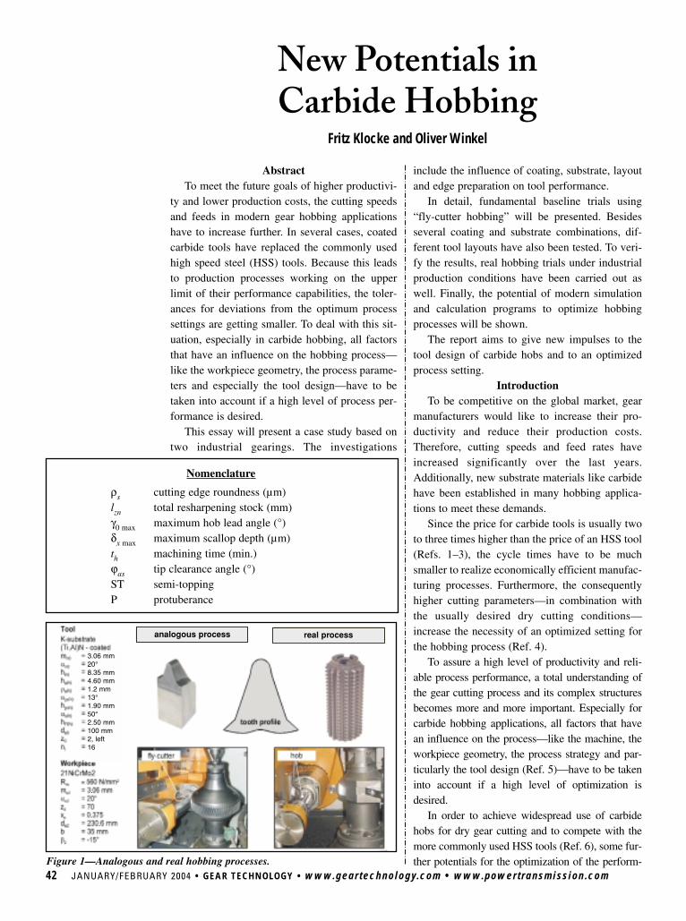
42 JANUARY/FEBRUARY 2004 • GEAR TECHNOLOGY • www.geartechnology.com • www.powertransmission.com
AbstractTo meet the future goals of higher productivi-
ty and lower production costs, the cutting speedsand feeds in modern gear hobbing applicationshave to increase further. In several cases, coatedcarbide tools have replaced the commonly usedhigh speed steel (HSS) tools. Because this leadsto production processes working on the upperlimit of their performance capabilities, the toler-ances for deviations from the optimum processsettings are getting smaller. To deal with this sit-uation, especially in carbide hobbing, all factorsthat have an influence on the hobbing process—like the workpiece geometry, the process parame-ters and especially the tool design—have to betaken into account if a high level of process per-formance is desired.
This essay will present a case study based ontwo industrial gearings. The investigations
include the influence of coating, substrate, layoutand edge preparation on tool performance.
In detail, fundamental baseline trials using“fly-cutter hobbing” will be presented. Besidesseveral coating and substrate combinations, dif-ferent tool layouts have also been tested. To veri-fy the results, real hobbing trials under industrialproduction conditions have been carried out aswell. Finally, the potential of modern simulationand calculation programs to optimize hobbingprocesses will be shown.
The report aims to give new impulses to thetool design of carbide hobs and to an optimizedprocess setting.
IntroductionTo be competitive on the global market, gear
manufacturers would like to increase their pro-ductivity and reduce their production costs.Therefore, cutting speeds and feed rates haveincreased significantly over the last years.Additionally, new substrate materials like carbidehave been established in many hobbing applica-tions to meet these demands.
Since the price for carbide tools is usually twoto three times higher than the price of an HSS tool(Refs. 1–3), the cycle times have to be muchsmaller to realize economically efficient manufac-turing processes. Furthermore, the consequentlyhigher cutting parameters—in combination withthe usually desired dry cutting conditions—increase the necessity of an optimized setting forthe hobbing process (Ref. 4).
To assure a high level of productivity and reli-able process performance, a total understanding ofthe gear cutting process and its complex structuresbecomes more and more important. Especially forcarbide hobbing applications, all factors that havean influence on the process—like the machine, theworkpiece geometry, the process strategy and par-ticularly the tool design (Ref. 5)—have to be takeninto account if a high level of optimization isdesired.
In order to achieve widespread use of carbidehobs for dry gear cutting and to compete with themore commonly used HSS tools (Ref. 6), some fur-ther potentials for the optimization of the perform-
New Potentials in Carbide Hobbing
Fritz Klocke and Oliver Winkel
Figure 1—Analogous and real hobbing processes.
ρs cutting edge roundness (µm)lzn total resharpening stock (mm)γ0 max maximum hob lead angle (°)δx max maximum scallop depth (µm)th machining time (min.)ϕas tip clearance angle (°)ST semi-toppingP protuberance
Nomenclature
analogous process real process
3.06 mm20°8.35 mm4.60 mm1.2 mm13°1.90 mm50°2.50 mm100 mm2, left16
.
..
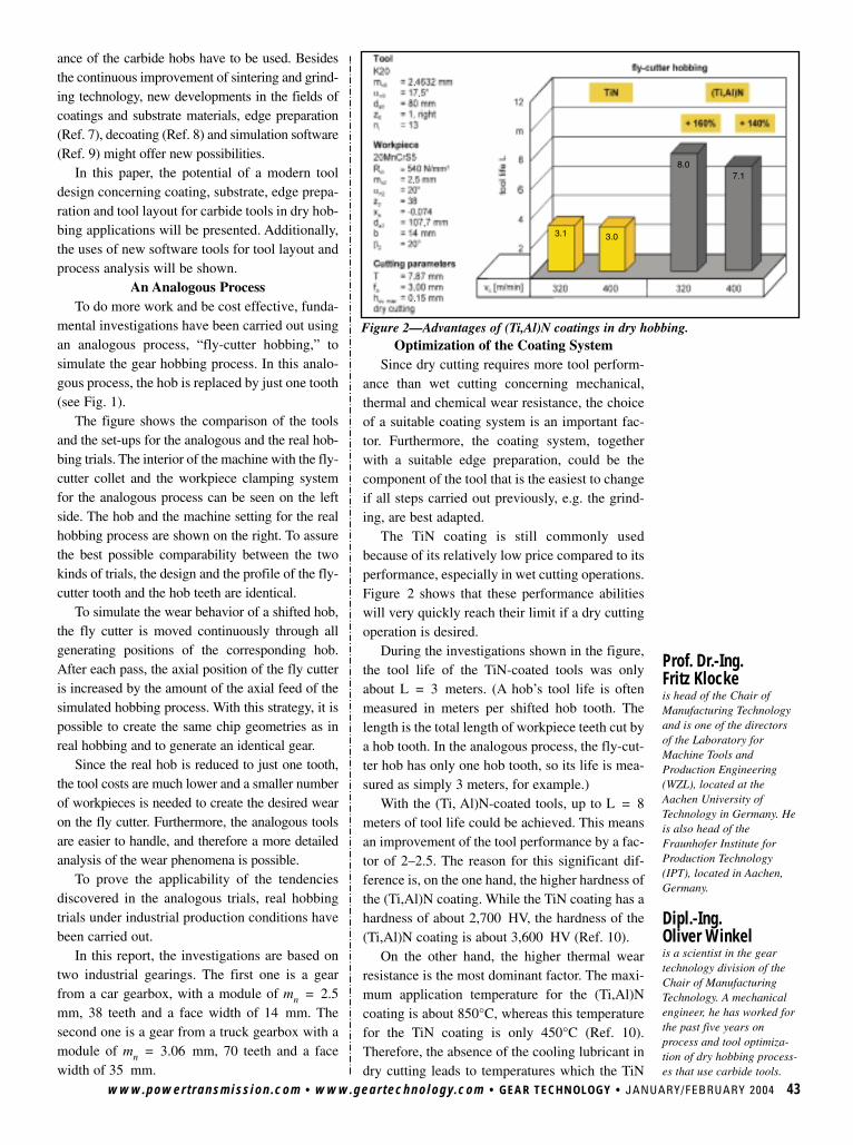
ance of the carbide hobs have to be used. Besidesthe continuous improvement of sintering and grind-ing technology, new developments in the fields ofcoatings and substrate materials, edge preparation(Ref. 7), decoating (Ref. 8) and simulation software(Ref. 9) might offer new possibilities.
In this paper, the potential of a modern tooldesign concerning coating, substrate, edge prepa-ration and tool layout for carbide tools in dry hob-bing applications will be presented. Additionally,the uses of new software tools for tool layout andprocess analysis will be shown.
An Analogous ProcessTo do more work and be cost effective, funda-
mental investigations have been carried out usingan analogous process, “fly-cutter hobbing,” tosimulate the gear hobbing process. In this analo-gous process, the hob is replaced by just one tooth(see Fig. 1).
The figure shows the comparison of the toolsand the set-ups for the analogous and the real hob-bing trials. The interior of the machine with the fly-cutter collet and the workpiece clamping systemfor the analogous process can be seen on the leftside. The hob and the machine setting for the realhobbing process are shown on the right. To assurethe best possible comparability between the twokinds of trials, the design and the profile of the fly-cutter tooth and the hob teeth are identical.
To simulate the wear behavior of a shifted hob,the fly cutter is moved continuously through allgenerating positions of the corresponding hob.After each pass, the axial position of the fly cutteris increased by the amount of the axial feed of thesimulated hobbing process. With this strategy, it ispossible to create the same chip geometries as inreal hobbing and to generate an identical gear.
Since the real hob is reduced to just one tooth,the tool costs are much lower and a smaller numberof workpieces is needed to create the desired wearon the fly cutter. Furthermore, the analogous toolsare easier to handle, and therefore a more detailedanalysis of the wear phenomena is possible.
To prove the applicability of the tendenciesdiscovered in the analogous trials, real hobbingtrials under industrial production conditions havebeen carried out.
In this report, the investigations are based ontwo industrial gearings. The first one is a gearfrom a car gearbox, with a module of mn = 2.5mm, 38 teeth and a face width of 14 mm. Thesecond one is a gear from a truck gearbox with amodule of mn = 3.06 mm, 70 teeth and a facewidth of 35 mm.
www.powertransmission.com • www.geartechnology.com • GEAR TECHNOLOGY • JANUARY/FEBRUARY 2004 43
Optimization of the Coating SystemSince dry cutting requires more tool perform-
ance than wet cutting concerning mechanical,thermal and chemical wear resistance, the choiceof a suitable coating system is an important fac-tor. Furthermore, the coating system, togetherwith a suitable edge preparation, could be thecomponent of the tool that is the easiest to changeif all steps carried out previously, e.g. the grind-ing, are best adapted.
The TiN coating is still commonly usedbecause of its relatively low price compared to itsperformance, especially in wet cutting operations.Figure 2 shows that these performance abilitieswill very quickly reach their limit if a dry cuttingoperation is desired.
During the investigations shown in the figure,the tool life of the TiN-coated tools was onlyabout L = 3 meters. (A hob’s tool life is oftenmeasured in meters per shifted hob tooth. Thelength is the total length of workpiece teeth cut bya hob tooth. In the analogous process, the fly-cut-ter hob has only one hob tooth, so its life is mea-sured as simply 3 meters, for example.)
With the (Ti, Al)N-coated tools, up to L = 8meters of tool life could be achieved. This meansan improvement of the tool performance by a fac-tor of 2–2.5. The reason for this significant dif-ference is, on the one hand, the higher hardness ofthe (Ti,Al)N coating. While the TiN coating has ahardness of about 2,700 HV, the hardness of the(Ti,Al)N coating is about 3,600 HV (Ref. 10).
On the other hand, the higher thermal wearresistance is the most dominant factor. The maxi-mum application temperature for the (Ti,Al)Ncoating is about 850°C, whereas this temperaturefor the TiN coating is only 450°C (Ref. 10).Therefore, the absence of the cooling lubricant indry cutting leads to temperatures which the TiN
Prof. Dr.-Ing. Fritz Klocke is head of the Chair ofManufacturing Technologyand is one of the directorsof the Laboratory forMachine Tools andProduction Engineering(WZL), located at theAachen University ofTechnology in Germany. Heis also head of theFraunhofer Institute forProduction Technology(IPT), located in Aachen,Germany.
Dipl.-Ing. Oliver Winkel is a scientist in the geartechnology division of theChair of ManufacturingTechnology. A mechanicalengineer, he has worked forthe past five years onprocess and tool optimiza-tion of dry hobbing process-es that use carbide tools.
Figure 2—Advantages of (Ti,Al)N coatings in dry hobbing.
.
.
.
.
.
.
.
.
3.1 3.0
7.18.0
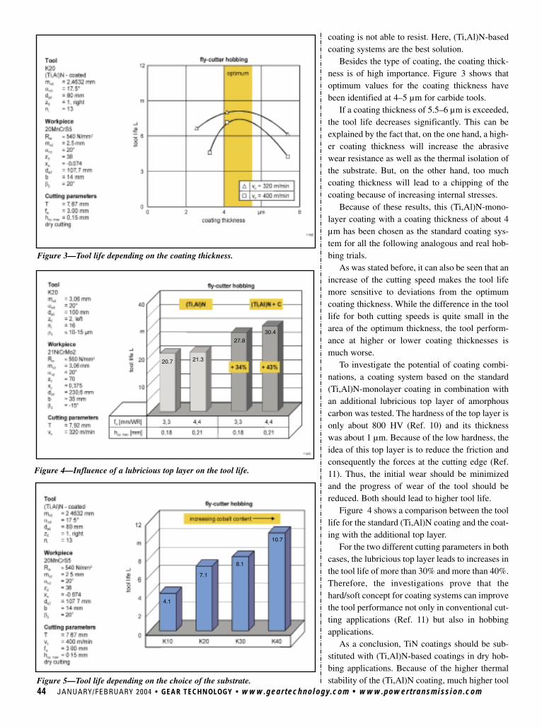
Figure 4—Influence of a lubricious top layer on the tool life.
coating is not able to resist. Here, (Ti,Al)N-basedcoating systems are the best solution.
Besides the type of coating, the coating thick-ness is of high importance. Figure 3 shows thatoptimum values for the coating thickness havebeen identified at 4–5 µm for carbide tools.
If a coating thickness of 5.5–6 µm is exceeded,the tool life decreases significantly. This can beexplained by the fact that, on the one hand, a high-er coating thickness will increase the abrasivewear resistance as well as the thermal isolation ofthe substrate. But, on the other hand, too muchcoating thickness will lead to a chipping of thecoating because of increasing internal stresses.
Because of these results, this (Ti,Al)N-mono-layer coating with a coating thickness of about 4µm has been chosen as the standard coating sys-tem for all the following analogous and real hob-bing trials.
As was stated before, it can also be seen that anincrease of the cutting speed makes the tool lifemore sensitive to deviations from the optimumcoating thickness. While the difference in the toollife for both cutting speeds is quite small in thearea of the optimum thickness, the tool perform-ance at higher or lower coating thicknesses ismuch worse.
To investigate the potential of coating combi-nations, a coating system based on the standard(Ti,Al)N-monolayer coating in combination withan additional lubricious top layer of amorphouscarbon was tested. The hardness of the top layer isonly about 800 HV (Ref. 10) and its thicknesswas about 1 µm. Because of the low hardness, theidea of this top layer is to reduce the friction andconsequently the forces at the cutting edge (Ref.11). Thus, the initial wear should be minimizedand the progress of wear of the tool should bereduced. Both should lead to higher tool life.
Figure 4 shows a comparison between the toollife for the standard (Ti,Al)N coating and the coat-ing with the additional top layer.
For the two different cutting parameters in bothcases, the lubricious top layer leads to increases inthe tool life of more than 30% and more than 40%.Therefore, the investigations prove that thehard/soft concept for coating systems can improvethe tool performance not only in conventional cut-ting applications (Ref. 11) but also in hobbingapplications.
As a conclusion, TiN coatings should be sub-stituted with (Ti,Al)N-based coatings in dry hob-bing applications. Because of the higher thermalstability of the (Ti,Al)N coating, much higher tool
44 JANUARY/FEBRUARY 2004 • GEAR TECHNOLOGY • www.geartechnology.com • www.powertransmission.com
Figure 3—Tool life depending on the coating thickness.
Figure 5—Tool life depending on the choice of the substrate.
..
.
..
...
4.1
7.1
8.1
10.7
20.7 21.3
27.8
30.4
.
.
..
.
.
.
.
.
.
..
. .
..
. .
...
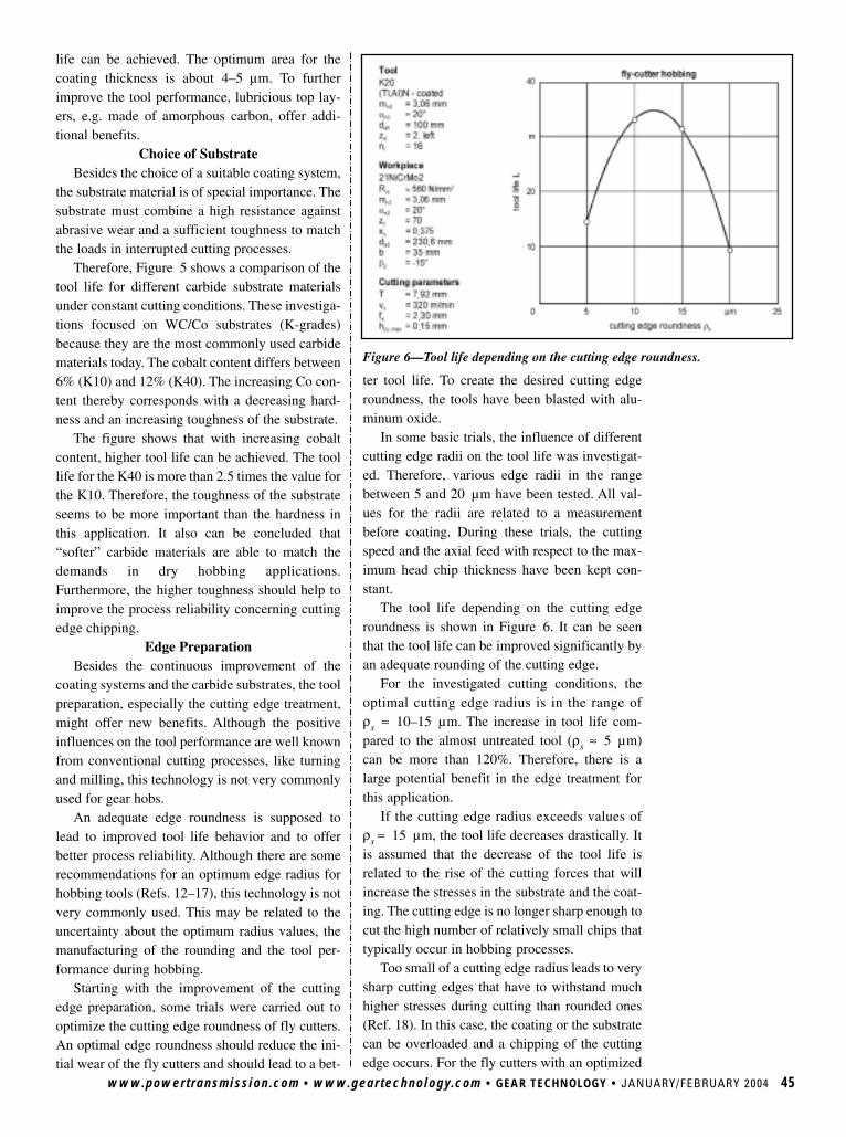
www.powertransmission.com • www.geartechnology.com • GEAR TECHNOLOGY • JANUARY/FEBRUARY 2004 45
life can be achieved. The optimum area for thecoating thickness is about 4–5 µm. To furtherimprove the tool performance, lubricious top lay-ers, e.g. made of amorphous carbon, offer addi-tional benefits.
Choice of SubstrateBesides the choice of a suitable coating system,
the substrate material is of special importance. Thesubstrate must combine a high resistance againstabrasive wear and a sufficient toughness to matchthe loads in interrupted cutting processes.
Therefore, Figure 5 shows a comparison of thetool life for different carbide substrate materialsunder constant cutting conditions. These investiga-tions focused on WC/Co substrates (K-grades)because they are the most commonly used carbidematerials today. The cobalt content differs between6% (K10) and 12% (K40). The increasing Co con-tent thereby corresponds with a decreasing hard-ness and an increasing toughness of the substrate.
The figure shows that with increasing cobaltcontent, higher tool life can be achieved. The toollife for the K40 is more than 2.5 times the value forthe K10. Therefore, the toughness of the substrateseems to be more important than the hardness inthis application. It also can be concluded that“softer” carbide materials are able to match thedemands in dry hobbing applications.Furthermore, the higher toughness should help toimprove the process reliability concerning cuttingedge chipping.
Edge PreparationBesides the continuous improvement of the
coating systems and the carbide substrates, the toolpreparation, especially the cutting edge treatment,might offer new benefits. Although the positiveinfluences on the tool performance are well knownfrom conventional cutting processes, like turningand milling, this technology is not very commonlyused for gear hobs.
An adequate edge roundness is supposed tolead to improved tool life behavior and to offerbetter process reliability. Although there are somerecommendations for an optimum edge radius forhobbing tools (Refs. 12–17), this technology is notvery commonly used. This may be related to theuncertainty about the optimum radius values, themanufacturing of the rounding and the tool per-formance during hobbing.
Starting with the improvement of the cuttingedge preparation, some trials were carried out tooptimize the cutting edge roundness of fly cutters.An optimal edge roundness should reduce the ini-tial wear of the fly cutters and should lead to a bet-
ter tool life. To create the desired cutting edgeroundness, the tools have been blasted with alu-minum oxide.
In some basic trials, the influence of differentcutting edge radii on the tool life was investigat-ed. Therefore, various edge radii in the rangebetween 5 and 20 µm have been tested. All val-ues for the radii are related to a measurementbefore coating. During these trials, the cuttingspeed and the axial feed with respect to the max-imum head chip thickness have been kept con-stant.
The tool life depending on the cutting edgeroundness is shown in Figure 6. It can be seenthat the tool life can be improved significantly byan adequate rounding of the cutting edge.
For the investigated cutting conditions, theoptimal cutting edge radius is in the range ofρs ≈ 10–15 µm. The increase in tool life com-pared to the almost untreated tool (ρs ≈ 5 µm)can be more than 120%. Therefore, there is alarge potential benefit in the edge treatment forthis application.
If the cutting edge radius exceeds values ofρs ≈ 15 µm, the tool life decreases drastically. Itis assumed that the decrease of the tool life isrelated to the rise of the cutting forces that willincrease the stresses in the substrate and the coat-ing. The cutting edge is no longer sharp enough tocut the high number of relatively small chips thattypically occur in hobbing processes.
Too small of a cutting edge radius leads to verysharp cutting edges that have to withstand muchhigher stresses during cutting than rounded ones(Ref. 18). In this case, the coating or the substratecan be overloaded and a chipping of the cuttingedge occurs. For the fly cutters with an optimized
Figure 6—Tool life depending on the cutting edge roundness.
.
.
.
..
.
.
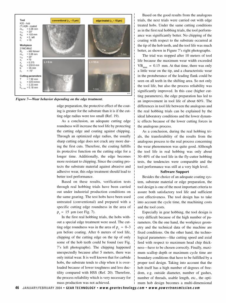
46 JANUARY/FEBRUARY 2004 • GEAR TECHNOLOGY • www.geartechnology.com • www.powertransmission.com
Based on the good results from the analogoustrials, the next trials were carried out with edgetreated hobs. Under the same cutting conditionsas in the first real hobbing trials, the tool perform-ance was significantly better. No chipping of thecoating with respect to the substrate occurred atthe tip of the hob teeth, and the tool life was muchbetter, as shown in Figure 7’s right photographs.
The trial was stopped after 10 meters of toollife because the maximum wear width exceededVBmax = 0.15 mm. At that time, there was onlya little wear on the tip, and a characteristic wearin the protuberance of the leading flank could beseen on all teeth in the shifting area. So not onlythe tool life, but also the process reliability wassignificantly improved. In this case (higher cut-ting parameters), the edge preparation has led toan improvement in tool life of about 60%. Thedifferences in tool life between the analogous andthe real hobbing trials can be explained by theideal laboratory conditions and the lower dynam-ic effects because of the lower cutting forces inthe analogous process.
As a conclusion, during the real hobbing tri-als, the transferability of the results from theanalogous process to the real process concerningthe wear phenomenon was quite good. Althoughthe tool life in real hobbing was only about30–40% of the tool life in the fly-cutter hobbingtests, the tendencies were comparable and thetool performance was still at a very high level.
Software SupportBesides the choice of an adequate coating sys-
tem, substrate material or edge preparation, thetool design is one of the most important criteria toassure both satisfactory tool life and sufficientcost effectiveness. The tool design has to takeinto account the cycle time, the machining costsand the tool costs.
Especially in gear hobbing, the tool design isvery difficult because of the high number of pa-rameters. On the one hand, the workpiece geom-etry and the technical data of the machine arefixed conditions. On the other hand, the techno-logical parameters—like cutting speed and axialfeed with respect to maximum head chip thick-ness—have to be chosen correctly. Finally, maxi-mum scallop depth or maximum cycle time areboundary conditions that have to be fulfilled by aproper tool design. Taking into account that thehob itself has a high number of degrees of free-dom, e.g. outside diameter, number of gashes,number of threads, usable length, etc., the opti-mum hob design becomes a multi-dimensional
edge preparation, the protective effect of the coat-ing is greater for the substrate than it is if the cut-ting edge radius were too small (Ref. 19).
As a conclusion, an adequate cutting edgeroundness will increase the tool life by protectingthe cutting edge and coating against chipping.Through an optimized edge radius, the usuallysharp cutting edge does not crack any more dur-ing the first cuts. Therefore, the coating fulfillsits protective function on the cutting edge for alonger time. Additionally, the edge becomesmore resistant to chipping. Since the coating pro-tects the substrate material against abrasive andadhesive wear, this edge treatment should lead tobetter tool performance.
Based on these results, verification teststhrough real hobbing trials have been carriedout under industrial production conditions onthe same gearing. The test hobs have been useduntreated (conventional) and prepared with aspecific cutting edge roundness in the area ofρs ≈ 15 µm (see Fig. 7).
In the first real hobbing trials, the hobs with-out a special edge treatment were used. The cut-ting edge roundness was in the area of ρs ≈ 0–3µm before coating. After 6 meters of tool life,chipping of the cutting edge on the tip of onlysome of the hob teeth could be found (see Fig.7’s left photographs). The chipping happenedunexpectedly because after 5 meters, there wasonly initial wear. It is well known that for carbidehobs, the substrate tends to chip when it is over-loaded because of lower toughness and less duc-tility compared with HSS (Ref. 20). Therefore,the process reliability which is very necessary formass production was not achieved.
Figure 7—Wear behavior depending on the edge treatment.
.
.
..
.
..

www.powertransmission.com • www.geartechnology.com • GEAR TECHNOLOGY • JANUARY/FEBRUARY 2004 47
problem.Since this problem usually cannot be solved
by hand, adequate software programs have tosupport the tool designer. This was the motivationfor WZL to create its own software tool, Hobbit.The program is able to calculate by boundaryiteration the optimum hob design out of a matrixof thousands of possible tool designs. Thus, theuser only has to enter his boundary conditionsconcerning machine and workpiece data as wellas desired cutting speeds and chip thickness.Then, the program calculates all possible tooldesigns that match the declared circumstancesand assesses them.
To illustrate the potential of such software sys-tems, Figure 8 shows two calculations for animproved hob design. The first case is an HSStool, the second one a carbide hob. Analogous tri-als have been carried out with both tool systems,so that the specified cutting parameters will resultin approximately equal tool life for the two basictool designs, which are shaded in gray. As shownin the figure, both hobs are not optimal designsfor their cycle time.
Therefore, certain boundary conditions weredeclared which are documented on Figure 8’s leftside. Afterwards, the calculation was done, andthe best results are presented in the chart on theright side of Figure 8. It can be seen that in bothcases, the main times could be decreased signifi-cantly. On top of each chart, the fastest tooldesigns are shown. Furthermore, the best designswith relatively small outside diameter (lower toolcost) and the best designs with a higher numberof starts are presented.
Figure 8 expresses two statements very clear-ly. The first is that, because of their totally differ-ent cutting parameters, HSS and carbide tools forthe same gear must have a different geometry.While the HSS hob is usually used at mediumcutting speeds and high chip thickness, the car-bide hob is used at high cutting speeds and lowerchip thickness. Therefore, the tool layout has tobe different.
The second statement is that, although the car-bide tool will be run at very high cutting speeds,the HSS tool will almost reach the same cycletime because of the higher achievable chip thick-ness. Since the carbide hob usually has to befaster than the HSS hob to be cost efficient, newdevelopments have to provide new benefits torealize improved cutting speeds and also higherallowable chip thickness.
As a conclusion, software tools, like Hobbit,
have to allow users to find the best tool design fortheir boundary conditions out of a huge numberof possible layouts. Furthermore, the user is ableto get quantitative information about which toolconcept (HSS or carbide) might be the best forhis application.
Even if an optimized tool design has beenidentified, the hobbing process still is very com-plex and hard to understand. Because of the com-plicated generating kinematics in combinationwith a complex tool geometry, the chip geome-tries in hobbing processes are not easy to calcu-late. Since the chip geometry correlates with theloads during cutting and the wear of the tool, it ishelpful to know the existing contact conditions.Therefore, WZL has developed another softwareprogram, named Sparta, which is able not only tosimulate the hobbing process and calculate thechip geometries but also to calculate characteris-tic process values to quantify the process.
Starting with the different chip geometries, theprogram illustrates the complex shape of theundeformed chips, as can be seen in Figure 9.Here, a three-flank chip geometry typical forhobbing processes is shown.
The X-axis shows the position on the cuttingedge, and the Y-axis represents the cutting direc-tion. The chip thickness is illustrated by theheight (Z-axis) of the diagram. It can be seen veryclearly that every point of the cutting edge has towithstand a different type of load. This makes thehobbing process so difficult to optimize becauseone coating/substrate system has to match allthese different demands.
However, several characteristic values—e.g.the distribution of the chip thickness or the con-tact length, the effective clearance angles, thechip volumes or the dynamic contact conditions
Figure 8—Example for a machining time-optimized hob.
.
.
.
.
.
.
.
.
.
.
.
.
.
.
.
.
.
threads
threads
Favorable hob - design
Favorable hob - design

48 JANUARY/FEBRUARY 2004 • GEAR TECHNOLOGY • www.geartechnology.com • www.powertransmission.com
between hob and workpiece—can be calculatedout of these data for the chip geometries.
These characteristic values can help the userget a deeper insight into his process than justjudging it by the maximum head chip thickness.This additional information can be used, on theone hand, to support a better process setting ortool design and, on the other hand, to analyzeprocesses and tools which have not performedsatisfactorily.
To give a practical example, Figure 10 showsthe typical wear of a fly cutter for the consideredgearing.
While the wear on the trailing flank is verysmall, the wear on the leading flank in the area ofthe protuberance is critical and sets the limit forthe tool life. Since analysis of the chip geometriesdid not lead to concrete ideas about this phenom-enon, additional calculations concerning the char-acteristic values have been carried out.
Two of those values are shown in Figure 11along the cutting edge to give first hints toexplain the observed wear.
Figure 11’s upper part shows the minimaleffective clearance angles, while its lower partshows the number of cuts. In this context, thenumber of cuts means the number of chips duringthe cutting of a whole workpiece in which theconsidered cutting edge section is involved. Onthe left side of each diagram, the leading flank isshown and the wear critical area of the protuber-ance is marked in gray.
It can be seen that wear was relatively small inthe area of the protuberances with effective clear-ance angles about 2°. This is related to the lowerpressure angle of only 13° compared to the pres-sure angle of 20° on the flanks. These low clear-ance angles lead to a bigger contact zone betweenthe workpiece and the tool in this area. The big-ger zone consequently results in higher frictionand thus higher temperatures and abrasive wear.
Furthermore, the number of cuts is significant-ly higher on the leading flank than on the trailingflank, especially in the area of the protuberance.Therefore, the corresponding cutting edge sectionhas to penetrate the workpiece more often. Thecombination of these two effects explains thewear phenomenon.
Improvements might be possible by increasingthe effective clearance angles at this point, forexample, by choosing a bigger tip clearance angleor, if possible, a profile modification with a high-er pressure angle in the protuberance.
As a conclusion, both software systems canhelp the user in better designing, analyzing andunderstanding the challenging hobbing process.Such programs will give valuable support to cre-ate technologically and economically efficientprocesses, especially in the field of dry hobbingwith coated carbide tools because of the smallerwindows for optimal process settings.
ConclusionsThere are still large potentials in the field of
dry hobbing with coated carbide tools. Thisincludes the further optimization of the coatingsystem, the substrate material, defined edgepreparation and tool design. The process reliabil-ity of the carbide hobs should especially be a keyaspect because these tools are usually applied inmass production.
In this paper, the investigations were based ondifferent (Ti,Al)N-based coating systems becauseTiN coatings are not suitable in dry hobbingapplications. Concerning tool life, the coating
Figure 11—Analysis of two important parameters in hobbing.
Figure 9—3-D illustration of a simulated chip’s geometry.
Figure 10—Typical wear on a fly cutter.
.
.
..
.
.
.
.
.
..
.
.
.
.
.
..
.
.
.
25,000
20,000
15,000
10,000
5,000
.
Tell Us What You Think . . . Send e-mail to [email protected] to• Rate this article• Request more information• Contact the authors or organization mentioned• Make a suggestionOr call (847) 437-6604 to talk to one of our editors!
thickness should not exceed 4–5 µm. Lubricioustop layers, e.g. amorphous carbon, can lead to anincrease in tool life by 30–40%.
The trials on different carbide materialsproved that the requirements of a dry hobbingprocess with regard to substrate are concernedprimarily with toughness, not hardness.Therefore, substrates with higher cobalt contentshowed better tool life.
Furthermore, investigations to determine asuitable range for cutting edge rounding and itspotential concerning the tool life of carbide hobswere performed. The results show that a cuttingedge roundness of ρs ≈ 10–15 µm improves thewear behavior of the carbide tools in fly-cutterhobbing significantly. The results from the analo-gous process were verified by real process trialscarried out under conditions of industrial produc-tion. Although the tool life was much smaller inreal hobbing, the better tool life and higherprocess reliability could be achieved.
Finally, software tools, like Hobbit andSparta, have been presented to point out theirability to support the user in his efforts to deter-mine optimal tool designs and process settings aswell as to achieve a better process understanding.Additionally, the software tool Sparta should alsohelp to analyze and give hints to improve insuffi-cient tool or process performances. Especially inthe field of dry hobbing with carbide tools,because of the smaller windows of the optimalprocess settings, such programs will give valu-able support to create technologically and eco-nomically efficient processes.
Only with an optimized tool design withregard to substrate, coating and layout, one willhave the chance to run carbide hobs with veryhigh speeds and feeds.
Therefore, it can be summarized that carbidehobbing is still a challenge. But there are also newbenefits to using the high potential of this substratematerial, especially since HSS materials seem tohave reached their performance limits.
Systematic research activities in combinationwith a consequent software development will benecessary to support the end user in his efforts tomeet future demands.
AcknowledgmentsThe investigations in the present paper were
conducted as a part of the Brite-EuRam projectCAPCAT (project no. BE97-4739), which wasfinanced by the European Commission.
The authors express their sincere apprecia-tion to project partners CemeCon GmbH,
Plansee Tizit GmbH, Samputensili S.p.A. andSVA AB for the supply of the tools.Furthermore, we wish to record our gratitude toScania CV AB and Volvo Car Corp. for theirsupport during the trials. r
References1. Mundt, A. “Erfolgreich Wälzfräsen ohne Kühlschmierstoff,”Proceedings of the 40th Conference “Zahnrad- und Getriebe-untersuchungen,” Aachen, Germany, April 21–22, 1999.2. LMT-Fette. “Production Increase When Hobbing with CarbideHobs,” Gear Technology, Vol. 15, No. 1, Jan./Feb. 1998, pp. 20–22.3. Klocke, F, C. Escher and M. Vüllers. “Dry Hobbing—Efficient andEcological,” Proceedings of the International Conference on Gears,VDI report 1230, VDI-Verlag, 1996, pp. 509–523.4. Peiffer, K. “Trockenwälzfräsen – Chance oder Risiko?” Proceedingsof the 40th Conference “Zahnrad- und Getriebeuntersuchungen,”Aachen, Germany, April 21–22, 1999.5. Kammermeier, D. “Staubtrocken läuft wie geschmiert –Werkzeuglösungen zur Trockenbearbeitung,” Proceedings of theConference “Trockenbearbeitung: Drehen, Fräsen, Bohren,” VDIreport 1532, VDI-Verlag, 2000, pp. 119–136.6. Klocke, F., and M. Kleinjans. “Verschleißmechanismen beimWälzfräsen mit beschichteten HSS-Werkzeugen im Trockenschnitt,”Proceedings of the 42nd Conference “Zahnrad- und Getriebeunter-suchungen,” Aachen, Germany, May 16–17, 2001.7. Klocke, F., and O. Winkel. “Hartmetallwerkzeuge zumHochleistungswälzfräsen – Prozessauslegung und Werkzeug-gestaltung,” Proceedings of the 42nd Conference “Zahnrad- undGetriebeuntersuchungen,” Aachen, Germany, May 16–17, 2001. 8. Klocke, F., and M. Kleinjans. “Aufbereitung vonHartmetallwälzfräsern – Probleme, Lösungsansätze und Potentiale,”Proceedings of the 43rd Conference “Zahnrad- und Getriebe-untersuchungen,” Aachen, Germany, April 24–25, 2002. 9. Weck, M., O. Hurasky-Schönwerth and W. Winter. “ManufacturingSimulation for the Analysis of the Gear Hobbing Process,”Proceedings of the International Conference on Gears, VDI report1665, VDI-Verlag, 2000, pp. 145–158.10. CemeCon AG. “Markenwerkzeuge durch individue lleBeschichtungen,” CemeCon AG, Würselen, Germany, 2001.11. Klocke, F., T. Krieg and J. Grams. “Non-adhesive coatings for cut-ting applications,” Proceedings of THE Coatings in ManufacturingEngineering, Hannover, Germany, May 9–10, 2001, pp. T9/1–9/10.12. Venohr, G. “Beitrag zum Einsatz von Hartmetall-Werkzeugenbeim Wälzfräsen, ” Ph.D. Dissertation, Aachen University ofTechnology, Aachen, Germany, 1985.13. Sulzer, G. “Hochleistungswälzfräsen als Trockenbearbeitung,”Trockenbearbeitung: Bearbeitung metallischer Werkstoffe ohneKühlschmiermittel, expert-Verlag, Renningen-Malmsheim, Germany,1998.14. Knöppel, D. “Trockenbearbeitung beim Hochgeschwin-digkeitswälzfräsen mit beschichteten Hartmetall-Werkzeugen,”Ph.D. Dissertation, Aachen University of Technology, Aachen,Germany, 1996.15. König, W., and K. Peiffer. “Wälzfräsen mit Hartmetall-Werkzeugen,” Industrie-Anzeiger, Vol. 109, No. 13, 1987, pp. 36–37.16. Maiuri, T. J. “Synopsis of the Evolution of Gear Hobbing,”Company paper of The Gleason Works, Rochester, New York, U.S.A.,1998.17. Schlarb, G. and K. Switzer. “Dry Hobbing Process TechnologyRoad Map,” Gear Technology, Vol. 18, No. 2, March/April 2001, pp.14–21.18. Bouzakis, K.-D., N. Vidakis and N. Michailidis. “Failure mecha-nisms of thin hard PVD coatings in cutting applications,” Proceedingsof THE Coatings in Manufacturing Engineering, Thessaloniki,Greece, Oct. 14–15, 1999, pp. 35–64.19. Klocke, F., and O. Winkel. “Hartmetallwerkzeuge zumHochleistungswälzfräsen– Technologische und wirtschaftlicheProzessauslegung,” Proceedings of the 43rd Conference “Zahnrad-und Getriebeuntersuchungen,” Aachen, Germany, April 24–25, 2002.20. Cooper, Charles M. “Cutting Tools Roundup,” Gear Technology,Vol. 16, No. 3, May/June 1999, pp. 17–23.
www.powertransmission.com • www.geartechnology.com • GEAR TECHNOLOGY • JANUARY/FEBRUARY 2004 49
This paper was presentedat the ASME/AGMA 2003International PowerTransmission and GearingConference, held Sept. 3–5,2003, in Chicago, Illinois,U.S.A. It was presentedunder the title “Potential ofCarbide Tools for HighPerformance Hobbing” andpublished under that title inProceedings of the 2003ASME Design EngineeringTechnical Conferences &Computers and Informationin Engineering Conference.It is republished here withASME’s permission.

Join the thousands who visit every day. Log on to www.powertransmission.com to find suppliers
of the components you need.
The Ultimate Shopping Mall for Power Transmission Components
powertransmission.com™
• Gears • Bearings• Motors• Speed Reducers
• Sprockets• Actuators• Linear Motion … and more
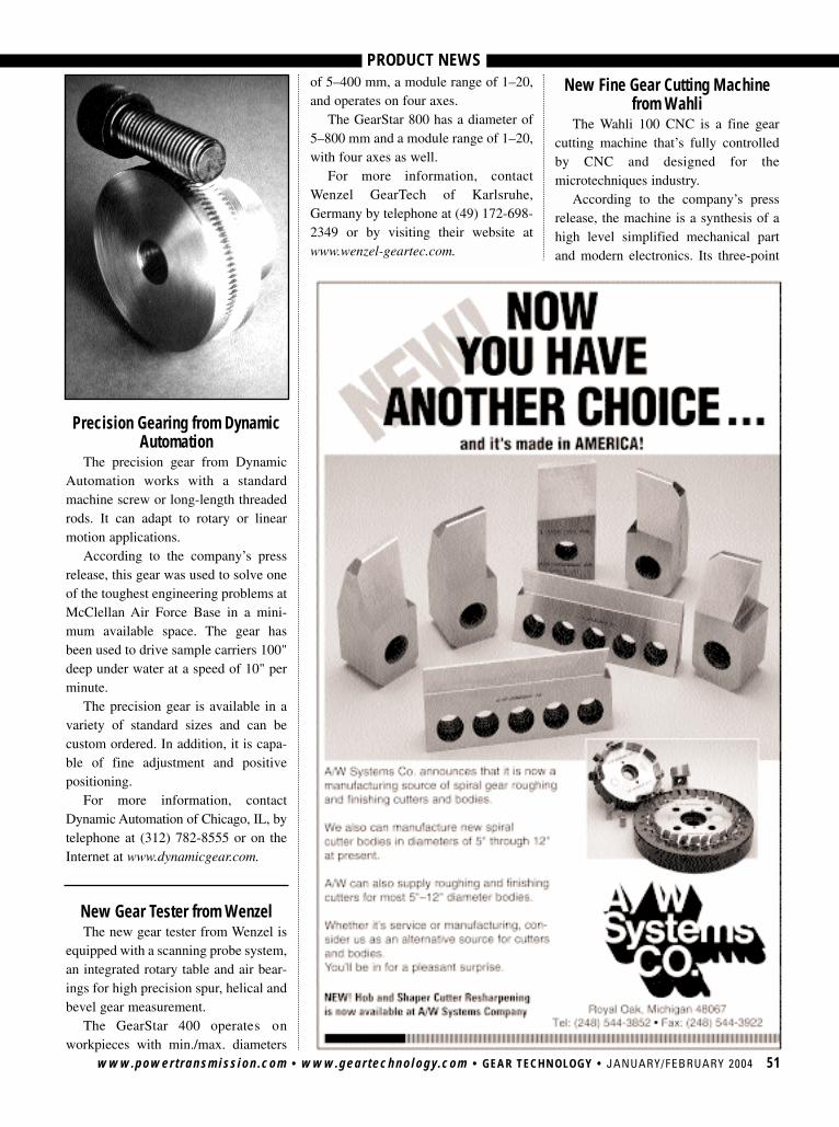
www.powertransmission.com • www.geartechnology.com • GEAR TECHNOLOGY • JANUARY/FEBRUARY 2004 51
Precision Gearing from DynamicAutomation
The precision gear from DynamicAutomation works with a standardmachine screw or long-length threadedrods. It can adapt to rotary or linearmotion applications.
According to the company’s pressrelease, this gear was used to solve oneof the toughest engineering problems atMcClellan Air Force Base in a mini-mum available space. The gear hasbeen used to drive sample carriers 100"deep under water at a speed of 10" perminute.
The precision gear is available in avariety of standard sizes and can becustom ordered. In addition, it is capa-ble of fine adjustment and positivepositioning.
For more information, contactDynamic Automation of Chicago, IL, bytelephone at (312) 782-8555 or on theInternet at www.dynamicgear.com.
New Gear Tester from WenzelThe new gear tester from Wenzel is
equipped with a scanning probe system,an integrated rotary table and air bear-ings for high precision spur, helical andbevel gear measurement.
The GearStar 400 operates onworkpieces with min./max. diameters
PRODUCT NEWSof 5–400 mm, a module range of 1–20,and operates on four axes.
The GearStar 800 has a diameter of5–800 mm and a module range of 1–20,with four axes as well.
For more information, contactWenzel GearTech of Karlsruhe,Germany by telephone at (49) 172-698-2349 or by visiting their website atwww.wenzel-geartec.com.
New Fine Gear Cutting Machinefrom Wahli
The Wahli 100 CNC is a fine gearcutting machine that’s fully controlledby CNC and designed for themicrotechniques industry.
According to the company’s pressrelease, the machine is a synthesis of ahigh level simplified mechanical partand modern electronics. Its three-point
Tell Us What You Think . . . Send e-mail to [email protected] to• Rate this column• Make a suggestion Or call (847) 437-6604 to talk to one of our editors!
52 JANUARY/FEBRUARY 2004 • GEAR TECHNOLOGY • www.geartechnology.com • www.powertransmission.com
PRODUCT NEWSstructure is welded and isostatic. Thereis a numerical interpolation for eachfeed axis. The high rapid traversingspeed is rated at 4 meters per minute,and the spindle operates at a speed of15,000 RPM.
For more information, contact WahliLtd. of Safnern, Switzerland, by tele-phone at (41) 32-356-0273 or theInternet at www.lambert-wahli.ch.
Gear Material from IntechIntech Power-Core is a hybrid com-
posite gear material that wraps around asturdy metal core.
According to the company’s pressrelease, the hybrid gear design features asturdy material that is gravity-cast direct-ly onto a rugged, knurled metal core. Thegear material is engineered to offer highperformance tensile and flexural proper-ties over a range of operating conditions.Gear teeth are hobbed into the outer plas-tic portion of the gear material.
A bore directly machined into themetal core secures the shaft connectionthat enables the designer to attach thecomposite gear using traditional metalgear methods.
A gear blank is mounted directlyonto an arbor of the hobbing machineand enables the cut of a precision boreinto the metal, serving as a referencepoint for the gear’s critical dimensions.
For more information, contact IntechCorp. of Closter, NJ, by telephone at(201) 767-8066 or on the Internet atwww.intechpower.com.
Corrections • Corrections • Corrections
A number was omitted from one of the equations in “Application ofStatistical Stability and Capability for Gear Cutting Machine AcceptanceCriteria.” The article was written by Thomas J. “Buzz” Maiuri and waspublished in Gear Technology’s November/December 2003 issue. Theomission occurred on page 38, in the equation about the lower capabilityindex (CPL).
The CPL equation should have included a 3 in the denominator, like thedenominator for the upper capability index (CPU). So the CPL equationshould have read:
Also, in the industry news section of the November/December 2003issue of Gear Technology, on page 18, we reported that Applied Processspecializes in austempering non-ferrous materials. The company’s cor-rect specialty is austempering, a high performance heat treating processfor ferrous materials.
We apologize for any inconvenience.—The Editors

www.powertransmission.com • www.geartechnology.com • GEAR TECHNOLOGY • JANUARY/FEBRUARY 2004 53
ADVERTISER INDEXUSE RAPID READER RESPONSE to contact any advertiser in this issue
www.geartechnology.com/rrr.htmRapid Reader Response: It’s FAST! It’s EASY! It’s ONLY ONLINE!
Advertiser Page Phone E-mail Internet
American Metal Treating Co. 54 (216) 431-4492 [email protected] www.americanmetaltreating.com
Arrow Gear Co. 4 (630) 969-7640 [email protected] www.arrowgear.com
A/W Systems Co. 51 (248) 544-3852
B&R Machine and Gear Corp. 17 (800) 238-0651 [email protected] www.brgear.com
Barit International Corp. 4, 52 (847) 272-8128 [email protected] www.barit.com
Bourn & Koch Machine Tool Co. 17 (815) 965-4013 [email protected] www.bourn-koch.com
Clydesdale Forge Co. 12 (44) (1384) 252587 [email protected] www.clydesdale-forge.co.uk
Colonial Tool Group Inc. 6 (313) 965-8680 [email protected] www.colonialtool.com
De.Ci.Ma SpA 13 (39) (051) 611-7889 [email protected] www.decimaspa.it
Dr. Kaiser (S.L. Munson) 11 (800) 775-1390 [email protected]
E-GT 14 (847) 437-6604 [email protected] www.geartechnology.com
Fässler Corp. 40 (414) 769-0072 [email protected] www.faessler-ag.ch
Forest City Gear 8 (815) 623-2168 www.fcgear.com
The Gear Industry Home Page 19 (847) 437-6604 [email protected] www.geartechnology.com
Gear Motions Inc. 55 (315) 488-0100 [email protected] www.gearmotions.com
The Gear Works – Seattle Inc. 54 (206) 762-3333 [email protected] www.thegearworks.com
Gleason Corp. IFC, 54, 55 (585) 473-1000 [email protected] www.gleason.com
Gleason Cutting Tools Corp. 1, 54, 55 (815) 877-8900 [email protected] www.gleason.com
Greg Allen Co. 16 (440) 331-0038 [email protected] www.gallenco.com
Insco Corp. 41 (978) 448-6368 [email protected] www.inscocorp.com
ITW Heartland 41 (320) 762-8782 [email protected] www.itwgears.com
Kapp Technologies 3 (303) 447-1130 [email protected] www.kapp-usa.com
KissSoft AG 13 (41) (55) 264-2030 [email protected] www.kisssoft.ch
Koro Sharpening Service 54 (763) 425-5247 [email protected] www.koroind.com
Liebherr Gear Technology Co. 5 (734) 429-7225 [email protected] www.liebherr.com
mG miniGears North America 18 (757) 627-4554 [email protected] www.minigears.com
Midwest Gear & Tool Inc. 16 (586) 754-8923 [email protected]
Mitsubishi Gear Technology Center IBC (248) 669-6136 [email protected] www.mitsubishigearcenter.com
Nordex Inc. 12 (203) 775-4877 [email protected] www.nordex.com
powertransmission.com 50 (847) 437-6604 [email protected] www.powertransmission.com
The Purdy Corp. 10 (860) 649-0000 [email protected] www.purdytransmissions.com
Star-SU Inc. OBC, 54 (847) 649-1450 [email protected] www.star-su.com
Vermont Machine Tool Co. 6 (802) 885-4521 www.vermontmachinetool.com
ad index 12/18/03 2:28 PM Page 68
SERVICE
CLASSIFIEDS
Rates—Line Classified: 1" minimum, $325. Additional lines $45 per line (8 lines per inch). Display Classified: 3" minimum: 1X—$735, 3X—$685 per
insertion, 6X—$645 per insertion. Additional per inch: 1X—$255, 3X—$235 per insertion, 6X—$225 per insertion. Color Classified: Add $150 per
insertion for color. Gear Technology will set type to advertiser’s layout or design a classified ad at no extra charge. Payment: Full payment must accom-
pany classified ads. Send check drawn in U.S. funds on a U.S. bank or Visa/MasterCard number and expiration date to Gear Technology, P.O. Box 1426,
Elk Grove Village, IL 60009. Agency Commission: No agency commission on classified ads. Materials Deadline: Ads must be received by the 15th of
the month, two months prior to publication. Acceptance: Publisher reserves the right to accept or reject advertisements at his discretion.
www.gleason.com
SPECIALIZED GEAR SERVICES
1000 University Ave., P.O. Box 22970 Rochester, NY 14692-2970 U.S.A.
Phone: 585/473-1000 Fax: 585/461-4348
E-mail: [email protected]
• CONTRACT METROLOGY SERVICES
• CURVIC COUPLING GRINDING& INSPECTION
• BEVEL & CYLINDRICALDEVELOPMENTS & PROTOTYPES
• APPLICATION ENGINEERINGSUPPORT & DESIGN SERVICES
• HEAT TREATMENT
• REPLACEMENT HELICAL GUIDES FORSHAPERS, INCLUDING FELLOWS
• CONTRACT METROLOGY SERVICES
• CURVIC COUPLING GRINDING& INSPECTION
• BEVEL & CYLINDRICALDEVELOPMENTS & PROTOTYPES
• APPLICATION ENGINEERINGSUPPORT & DESIGN SERVICES
• HEAT TREATMENT
• REPLACEMENT HELICAL GUIDES FORSHAPERS, INCLUDING FELLOWS
www.gleason.com
PICK UP AND DELIVERY IN MANY AREAS
C O R P O R A T I O N1351 Windsor Road
Loves Park, IL 61111 U.S.A.Phone: 815/877-8900
Fax: 815/877-0264E-mail: [email protected]
• BROACH SHARPENING
• HOB SHARPENING
• SHAVING CUTTER GRINDING
• THIN FILM COATING
• CUSTOM HEAT TREAT SERVICE
• REPLACEMENT HELICAL GUIDES FOR SHAPERS, INCLUDING FELLOWS
• BROACH SHARPENING
• HOB SHARPENING
• SHAVING CUTTER GRINDING
• THIN FILM COATING
• CUSTOM HEAT TREAT SERVICE
• REPLACEMENT HELICAL GUIDES FOR SHAPERS, INCLUDING FELLOWS
WHEN IT HAS TO BE RIGHT
• Gear Grinding to 94"• Industrial Gears to 250"• Turbo Compressor Gears• Custom Drives• Spline Broaching• Gear Metrology • Stock Planetary Speed Reducers
GGGGEEEEAAAARRRRBBBBOOOOXXXX RRRREEEEPPPPAAAAIIIIRRRR
ISO-9001
www. theg earworks .com
Custom Gear Services Since 1946
The Gear Works—Seattle, Inc.500 S. Portland StreetSeattle, WA 98108-0886Phone: (206) 762-3333Fax: (206) 762-3704E-mail: [email protected]
Induction Hardening Specialists in Tooth by ToothContour Hardening of InternalSpur, helical and bevel gears
American Metal Treating CompanyCleveland, Ohio
Phone: (216) 431-4492 • Fax: (216) 431-1508Web: www.americanmetaltreating.com
E-mail: [email protected]
Breakdown Service Available
Our gear hardening equipmentincludes 5 NATCO submergedprocess machines and 5 AJAXCNC-controlled gear scanningmachines. Tooth by tooth gearhardening from .5DP-10DP, up to15 tons, 200" diameter.
Sharpening Servicefor hobs, milling cutters
shaper cutters, shaving cutters.
Thin film coatings
5200 Prairie Stone Parkway, Suite 100
Hoffman Estates, IL 60192
Tel.: (847) 649 -1450 - Fax: (847) 649-0112
2083 W.M-55, West Branch, MI 48661
1-888-Resharp 1-888-737-4277
Tel.: (989) 345 -2865 - Fax: (989) 345-5660
1580 Progress Dr., Richmond, IN 47374
Tel.: (765) 935 -7424 - Fax: (765) 935-7631
[email protected] www.star-su.com
KORO SHARPENING SERVICE9530 - 85TH AVENUE NO.
MAPLE GROVE, MN [email protected]
HOB SHARPENING(763) 425-5247
� THIN FILM COATINGS �HSS & Carbide up to 5” Dia.
Straight Gash,Sharpened & InspectedPer AGMA STANDARDS
Quick Turnaround
54 JANUARY/FEBRUARY 2004 • GEAR TECHNOLOGY • www.geartechnology.com • www.powertransmission.com

MANUFACTURING ENGINEER
GLEASON CORPORATION
www.gleason.com
Gleason is the world’s most comprehensiveresource for gear manufacturing technolo-gy. We offer a comprehensive gear cuttingmachine program for every gear hobbing,milling and grinding application for cylin-drical and bevel gears. To learn more aboutour products and services or to find keycontact information, see our Web site.
GLEASON CUTTING TOOLSCORPORATION
Gleason Cutting Tools Corporation is theleading gear cutting tool manufacturer inNorth America. We offer a wide variety ofform-relieving milling cutters, hobs, shapercutters, shaving cutters and CBN-plated formgrinding wheels as well as our engineering,coating, heat treating, metallurgical, toolsharpening and reconditioning services.
www.gleason.com
WEBSITES
www.powertransmission.com • www.geartechnology.com • GEAR TECHNOLOGY • JANUARY/FEBRUARY 2004 55
HELP WANTED
WE’RE HIRINGGear Machine Repairman — Experienced troubleshooter for mechanicaland hydraulic repairs. Knowledge of electri-cal systems desirable. No travel.
Friendly work environment at our convenientnorthwest suburban Chicago location.
Profit sharing, health insurance.
CADILLAC MACHINERY CO. INC.1401 Lunt Avenue, Elk Grove, IL 60007E-mail: [email protected]
Fax your resume to 847-437-6618.
The Guy Down the Hall Wants His copy of
Gear Technology back
NOW!Sign up for your own copy at
www.geartechnology.com
Be on the Cover of Gear Technology
Send us your high-quality gear-related images for our consideration. It's a greatchance for FREE publicity.
Contact:Jean Bartz, Art Director
1425 Lunt AvenueElk Grove Village, IL 60007
M A C H I N E R YCADILLAC
Arrow Gear Co., a leading manufacturer of high qualityprecision gears, ideally located in Downers Grove, Illinois,approximately 20 miles west of Chicago, has an excellentcareer opportunity.
Candidate should have a background in planning opera-tional sequences of the machining of sophisticated powertransmission parts. Prior experience in a precision jobshop gear manufacturing environment is a must.Experience with CAD is required. Unigraphics a plus.
We offer highly competitive salaries, a comprehensiveCompany paid benefits package including life insurance,medical and dental plans. In addition to our Companyfunded pension plan, we offer a 401 (K) retirement savingsplan as well as a flexible spending account option.
If you are qualified and interested in being considered forthis position, fax, e-mail or mail your resume includingsalary history and requirements to:
Arrow Gear Co.2301 Curtiss Street, Downers Grove, IL 60515
Fax: 630-969-4535 • Email: [email protected]
Learn about one of the most modernfleets of Gear Grinders, including thenew Höfler 700 at Oliver Gear. See thelatest Reishauer Gear Grinding technolo-gy, at ISO 9001-2000 registered NixonGear, as well as the latest in CNC GearHobbing and cellular manufacturing.
www.gearmotions.com
GEAR MOTIONS, INC.
www.gearmotions.comwww.gearmotions.com
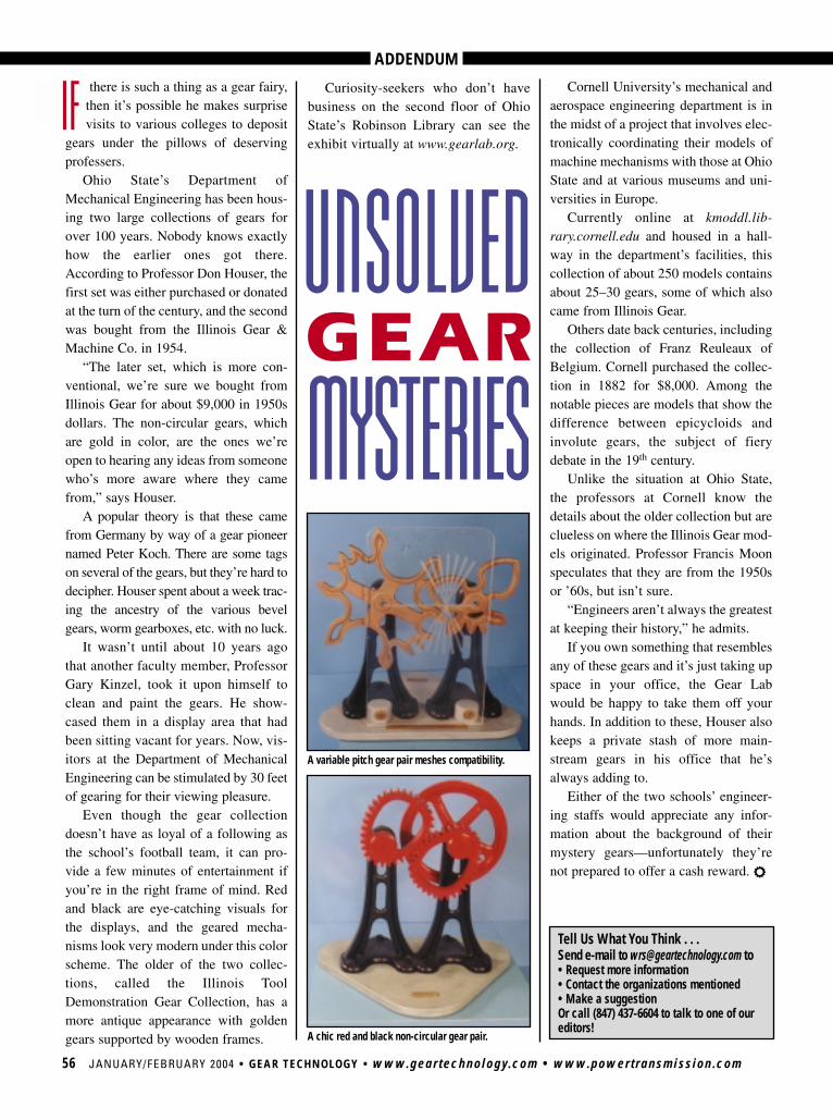
Tell Us What You Think . . . Send e-mail to [email protected] to• Request more information• Contact the organizations mentioned• Make a suggestionOr call (847) 437-6604 to talk to one of our editors!
ADDENDUM
56 JANUARY/FEBRUARY 2004 • GEAR TECHNOLOGY • www.geartechnology.com • www.powertransmission.com
there is such a thing as a gear fairy,then it’s possible he makes surprisevisits to various colleges to deposit
gears under the pillows of deservingprofessers.
Ohio State’s Department ofMechanical Engineering has been hous-ing two large collections of gears forover 100 years. Nobody knows exactlyhow the earlier ones got there.According to Professor Don Houser, thefirst set was either purchased or donatedat the turn of the century, and the secondwas bought from the Illinois Gear &Machine Co. in 1954.
“The later set, which is more con-ventional, we’re sure we bought fromIllinois Gear for about $9,000 in 1950sdollars. The non-circular gears, whichare gold in color, are the ones we’reopen to hearing any ideas from someonewho’s more aware where they camefrom,” says Houser.
A popular theory is that these camefrom Germany by way of a gear pioneernamed Peter Koch. There are some tagson several of the gears, but they’re hard todecipher. Houser spent about a week trac-ing the ancestry of the various bevelgears, worm gearboxes, etc. with no luck.
It wasn’t until about 10 years agothat another faculty member, ProfessorGary Kinzel, took it upon himself toclean and paint the gears. He show-cased them in a display area that hadbeen sitting vacant for years. Now, vis-itors at the Department of MechanicalEngineering can be stimulated by 30 feetof gearing for their viewing pleasure.
Even though the gear collectiondoesn’t have as loyal of a following asthe school’s football team, it can pro-vide a few minutes of entertainment ifyou’re in the right frame of mind. Redand black are eye-catching visuals forthe displays, and the geared mecha-nisms look very modern under this colorscheme. The older of the two collec-tions, called the Illinois ToolDemonstration Gear Collection, has amore antique appearance with goldengears supported by wooden frames.
Cornell University’s mechanical andaerospace engineering department is inthe midst of a project that involves elec-tronically coordinating their models ofmachine mechanisms with those at OhioState and at various museums and uni-versities in Europe.
Currently online at kmoddl.lib-rary.cornell.edu and housed in a hall-way in the department’s facilities, thiscollection of about 250 models containsabout 25–30 gears, some of which alsocame from Illinois Gear.
Others date back centuries, includingthe collection of Franz Reuleaux ofBelgium. Cornell purchased the collec-tion in 1882 for $8,000. Among thenotable pieces are models that show thedifference between epicycloids andinvolute gears, the subject of fierydebate in the 19th century.
Unlike the situation at Ohio State,the professors at Cornell know thedetails about the older collection but areclueless on where the Illinois Gear mod-els originated. Professor Francis Moonspeculates that they are from the 1950sor ’60s, but isn’t sure.
“Engineers aren’t always the greatestat keeping their history,” he admits.
If you own something that resemblesany of these gears and it’s just taking upspace in your office, the Gear Labwould be happy to take them off yourhands. In addition to these, Houser alsokeeps a private stash of more main-stream gears in his office that he’salways adding to.
Either of the two schools’ engineer-ing staffs would appreciate any infor-mation about the background of theirmystery gears—unfortunately they’renot prepared to offer a cash reward. r
Curiosity-seekers who don’t havebusiness on the second floor of OhioState’s Robinson Library can see theexhibit virtually at www.gearlab.org.
A variable pitch gear pair meshes compatibility.
A chic red and black non-circular gear pair.
UNSOLVEDMYSTERIES
IF
GEAR

MITSUBISHI GEAR MACHINES Gear Technology Center, 46992 Liberty Drive, Wixom, MI 48393 WWW.MITSUBISHIGEARCENTER.COM 248-669-6136 FAX 248-669-0614
Adden 12/18/03 2:07 PM Page 57
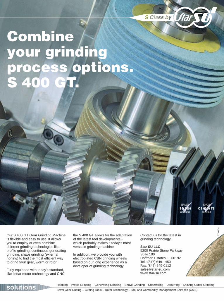
Combineyour grindingprocess options.S 400 GT.
the S 400 GT allows for the adaptationof the latest tool developments - which probably makes it today's most versatile grinding machine.
In addition, we provide you with electroplated CBN grinding wheelsbased on our long experience as adeveloper of grinding technology.
solutions Hobbing – Profile Grinding – Generating Grinding – Shave Grinding – Chamfering – Deburring – Shaving Cutter Grinding
Bevel Gear Cutting – Cutting Tools – Rotor Technology – Tool and Commodity Management Services (CMS)
Our S 400 GT Gear Grinding Machine is flexible and easy to use. It allowsyou to employ or even combine different grinding technologies likeprofile grinding, continuous generatinggrinding, shave grinding (externalhoning) to find the most efficient wayto grind your gear, worm or rotor.
Fully equipped with today's standard,like linear motor technology and CNC,
GT
010
4
Contact us for the latest ingrinding technology.
Star SU LLC5200 Prairie Stone ParkwaySuite 100Hoffman Estates, IL 60192Tel.: (847) 649-1450Fax: (847) [email protected]