ENGINE LUBRICATION & COOLING SYSTEMS LCterranoirk.ru/forums/manual/R20/lc.pdfENGINE LUBRICATION &...
34
ENGINE LUBRICATION & COOLING SYSTEMS SECTION LC CONTENTS ZD PRECAUTIONS AND PREPARATION............................2 Liquid Gasket Application Procedure ..........................2 Special Service Tools ..................................................2 ENGINE LUBRICATION SYSTEM ..................................3 Lubricating Circuit ........................................................3 Oil Pressure Check......................................................4 Oil Pump ......................................................................5 Oil Jet...........................................................................7 Oil Cooler .....................................................................8 ENGINE COOLING SYSTEM..........................................9 Cooling Circuit .............................................................9 System Check............................................................10 Water Pump ............................................................... 11 Thermostat .................................................................12 Water Outlet ...............................................................13 Radiator .....................................................................14 Cooling Fan (Crankshaft driven) ...............................15 EGR Cooler ...............................................................16 SERVICE DATA AND SPECIFICATIONS (SDS) ..........17 Engine Lubrication System........................................17 Engine Cooling System .............................................17 TD27Ti PREPARATION ..............................................................18 PRECAUTION................................................................19 ENGINE LUBRICATION SYSTEM ................................20 Lubrication Circuit ......................................................20 Oil Pressure Check....................................................21 Oil Pump ....................................................................22 Oil Filter Bracket ........................................................24 Oil Cooler ...................................................................25 Oil Jet.........................................................................26 ENGINE COOLING SYSTEM........................................27 Cooling Circuit ...........................................................27 System Inspection .....................................................28 Water Pump ...............................................................29 Thermostat .................................................................31 Radiator .....................................................................32 Cooling Fan ...............................................................33 SERVICE DATA AND SPECIFICATIONS (SDS) ..........34 Engine Lubrication System........................................34 Engine Cooling System .............................................34
Transcript of ENGINE LUBRICATION & COOLING SYSTEMS LCterranoirk.ru/forums/manual/R20/lc.pdfENGINE LUBRICATION &...

ENGINE LUBRICATION &COOLING SYSTEMS
SECTIONLCCONTENTS
ZD
PRECAUTIONS AND PREPARATION ............................2Liquid Gasket Application Procedure ..........................2Special Service Tools ..................................................2
ENGINE LUBRICATION SYSTEM ..................................3Lubricating Circuit ........................................................3Oil Pressure Check......................................................4Oil Pump......................................................................5Oil Jet...........................................................................7Oil Cooler.....................................................................8
ENGINE COOLING SYSTEM ..........................................9Cooling Circuit .............................................................9System Check............................................................10Water Pump...............................................................11Thermostat.................................................................12Water Outlet...............................................................13Radiator .....................................................................14Cooling Fan (Crankshaft driven) ...............................15EGR Cooler ...............................................................16
SERVICE DATA AND SPECIFICATIONS (SDS) ..........17Engine Lubrication System........................................17Engine Cooling System .............................................17
TD27Ti
PREPARATION ..............................................................18PRECAUTION ................................................................19ENGINE LUBRICATION SYSTEM ................................20
Lubrication Circuit ......................................................20Oil Pressure Check....................................................21Oil Pump....................................................................22Oil Filter Bracket ........................................................24Oil Cooler...................................................................25Oil Jet.........................................................................26
ENGINE COOLING SYSTEM ........................................27Cooling Circuit ...........................................................27System Inspection .....................................................28Water Pump...............................................................29Thermostat.................................................................31Radiator .....................................................................32Cooling Fan ...............................................................33
SERVICE DATA AND SPECIFICATIONS (SDS) ..........34Engine Lubrication System........................................34Engine Cooling System .............................................34

Liquid Gasket Application Procedurea. Use a scraper to remove all traces of old liquid gasket from
mating surfaces and grooves. Also, completely clean any oilfrom these areas.
b. Apply a continuous bead of liquid gasket to mating surfaces.(Use Genuine Liquid Gasket or equivalent.)I For oil pan, be sure liquid gasket diameter is 3.5 to 4.5 mm
(0.138 to 0.177 in).I For areas except oil pan, be sure liquid gasket diameter is
2.0 to 3.0 mm (0.079 to 0.118 in).c. Apply liquid gasket around the inner side of bolt holes (unless
otherwise specified).d. Assembly should be done within 5 minutes after coating.e. Wait at least 30 minutes before refilling engine oil and engine
coolant.
Special Service Tools*: Special tool or commercial equivalent
Tool numberTool name
Description
ST25051001*Oil pressure gauge
NT558
Measuring oil pressure
Maximum measuring range:2,452 kPa (24.5 bar, 25kg/cm 2, 356 psi)
ST25052000*Hose
NT559
Adapting oil pressure gaugeto cylinder block
EG17650301Radiator cap testeradapter
NT564
Adapting radiator cap testerto radiator filler neck and reser-voir tank cap
a: 28 (1.10) dia.b: 31.4 (1.236) dia.c: 41.3 (1.626) dia.Unit: mm (in)
SEM164F
AEM080
PRECAUTIONS AND PREPARATION ZD
LC-2

Lubricating Circuit
SLC361B
ENGINE LUBRICATION SYSTEM ZD
LC-3

Oil Pressure CheckWARNING:I Be careful not to burn yourself, as the engine and oil may
be hot.I Oil pressure check should be done in “Neutral” gear posi-
tion.1. Check oil level.2. Remove oil pressure switch.
3. Install pressure gauge.4. Start engine and warm it up to normal operating temperature.5. Check oil pressure with engine running under no-load.
Engine speedrpm
Approximate discharge pressurekPa (bar, kg/cm2, psi)
Idle speed2,0004,000
More than 147 (1.47, 1.5, 21)More than 539 (5.39, 5.5, 78)More than 736 (7.36, 7.5, 107)
If difference is extreme, check oil passage and oil pump.6. Install oil pressure switch with sealant.
Oil pressure switch:: 13 - 17 N⋅m (1.25 - 1.75 kg-m , 9 - 12 ft-lb)
SLC694A
JLC362B
ENGINE LUBRICATION SYSTEM ZD
LC-4

Oil PumpREMOVAL AND INSTALLATIONRefer to “TIMING GEAR” in EM section.DISASSEMBLY AND ASSEMBLY
I When installing oil pump, apply new engine oil to gears.
I When installing the inner and outer gear, face mating marktoward the oil pump cover as shown (left).
JLC363B
JLC364B
ENGINE LUBRICATION SYSTEM ZD
LC-5

OIL PUMP INSPECTIONUsing a feeler gauge, straightedge and micrometers, check thefollowing clearances:
Unit: mm (in)
Body to outer gear radial clearance q10.114 - 0.200
(0.0045 - 0.0079)
Inner gear to outer gear tip clearance q2 Less than 0.180 (0.0071)
Body to inner gear axial clearance q30.05 - 0.09
(0.0020 - 0.0035)
Body to outer gear axial clearance q40.050 - 0.105
(0.0020 - 0.0041)
Inner gear to brazed portion of housingclearance q5
0.045 - 0.091(0.0018 - 0.0036)
Regulator valve to oil pump coverclearance q6
0.040 - 0.097(0.0016 - 0.0038)
I If the tip clearance ( q2 ) exceeds the limit, replace gear set.I If body to gear clearances ( q1 , q3 , q4 , q5 ) exceed the limit,
replace oil pump body assembly.
REGULATOR VALVE INSPECTION1. Visually inspect components for wear and damage.2. Check oil pressure regulator valve sliding surface and valve
spring.3. Coat regulator valve with engine oil. Check that it falls smoothly
into the valve hole by its own weight.If damaged, replace regulator valve set or oil pump cover.
4. Check regulator valve to oil pump cover clearance.Clearance:
q6 : 0.040 - 0.097 mm (0.0016 - 0.0038 in)If it exceeds the limit, replace oil pump cover.
JLC365B
JLC366B
JLC367B
SLC369B
ENGINE LUBRICATION SYSTEM ZD
Oil Pump (Cont’d)
LC-6

OIL PRESSURE RELIEF VALVE AND BYPASS VALVEINSPECTION (For oil cooler)1. Inspect oil pressure relief valve for movement, cracks and
breaks by pushing the ball. If replacement is necessary, removevalve by prying it out with suitable tool.Install a new valve in place by tapping it.
2. Check oil pressure relief valve to oil cooler housing clearance.Clearance:
qC : 0.032 - 0.068 mm (0.0013 - 0.0027 in)If it exceeds the limit, replace oil cooler housing.
Oil JetINSPECTION (For timing chain)Make sure that the holes are not clogged. Clean them with a wireif necessary.Drive oil jet into place after positioning alignment mark on.
INSPECTION (For piston)1. Push cut-off valve of oil jet bolt with a clean resin or brass rod
and make sure that cut-off valve moves smoothly with properrepulsion.
2. Make sure that the oil jet passage is not clogged. Clean with awire if necessary.
When installing oil jet, align oil jet’s boss with hole on cylin-der block.
Oil jet:: 30 - 39 N⋅m (3.0 - 4.0 kg-m, 22 - 28 ft-lb)
SLC371B
SLC385B
FEM124
FEM125
ENGINE LUBRICATION SYSTEM ZD
Oil Pump (Cont’d)
LC-7

OIL FILTERThe oil filter is an element type. Refer to “Changing Oil Filter” in MAsection.
Oil Cooler
REMOVAL AND INSTALLATION1. Drain engine oil and coolant.
Remove catalyst and turbocharger. Refer to “CATALYST ANDTURBOCHARGER” in EM section.
2. Remove bolts A to C then remove oil cooler assembly.I Do not remove “D” nuts when removing oil cooler assem-
bly.Bolt length:
A: 20 mm (0.79 in)B: 45 mm (1.77 in)C: 65 mm (2.56 in)
3. Installation is in reverse order of removal.I Do not spill coolant on the drive belt.
INSPECTION1. Check oil cooler for cracks.2. Check oil cooler for clogging by blowing through coolant inlet.
If necessary, replace oil cooler assembly.
YLC030
JLC381B
ENGINE LUBRICATION SYSTEM ZD
Oil Jet (Cont’d)
LC-8

Cooling Circuit
YLC031
ENGINE COOLING SYSTEM ZD
LC-9

System CheckWARNING:Never remove the radiator cap when the engine is hot. Seriousburns could occur from high pressure coolant escaping fromthe radiator.Wrap a thick cloth around the cap. Slowly turn it a quarter turnto allow built-up pressure to escape. Carefully remove the capby turning it all the way.
CHECKING COOLING SYSTEM HOSESCheck hoses for the following:I Improper attachmentI LeaksI CracksI DamageI ChafingI Deterioration
CHECKING COOLING SYSTEM FOR LEAKSTo check for leakage, apply pressure to the cooling system with atester.
Testing pressure:157 kPa (1.57 bar, 1.6 kg/cm 2, 23 psi)
CAUTION:Higher pressure than specified may cause radiator damage.
CHECKING RADIATOR CAPTo check radiator cap, apply pressure to cap with a tester.
Radiator cap relief pressure:Standard
78 - 98 kPa(0.78 - 0.98 bar, 0.8 - 1.0 kg/cm 2, 11 - 14 psi)
Pull the negative pressure valve to open it.Check that it closes completely when released.
SLC134B
SLC135B
SMA967B
ENGINE COOLING SYSTEM ZD
LC-10

Water PumpCAUTION:I When removing water pump assembly, be careful not to
get coolant on drive belt.I Water pump cannot be disassembled and should be
replaced as a unit.I Always replace with new gasket.I After installing water pump, connect hose and clamp
securely, then check for leaks using radiator cap tester.Refer to MA section.
REMOVAL AND INSTALLATION1. Drain coolant from radiator and cylinder block.
Refer to MA section (“Changing Engine Coolant”, “ENGINEMAINTENANCE”).
2. Remove radiator upper hose.3. Remove radiator shroud.4. Remove cooling fan.5. Remove drive belt. Refer to MA section, “Checking Drive Belt”.6. Remove insulator.7. Remove vacuum pipe.8. Remove TDC sensor. Refer to EM section, “TDC sensor
removal and installation” in “TIMING GEAR”.9. Remove fan coupling with water pump.10. Install in the reverse order of removal.
JLC373B
ENGINE COOLING SYSTEM ZD
LC-11

INSPECTION1. Check for badly rusted or corroded body assembly and vane.2. Check for rough operation due to excessive end play.CAUTION:Do not disassemble water pump coupling assembly.
ThermostatSLC374B
YLC032
ENGINE COOLING SYSTEM ZD
Water Pump (Cont’d)
LC-12

REMOVAL AND INSTALLATION1. Drain engine coolant. Refer to MA section, “Changing Engine
Coolant”.2. Remove left side battery. (If so equipped)3. Remove radiator upper hose.4. Remove radiator shroud.5. Remove intake air duct, inlet pipe.6. Remove harness and connectors.7. Install in reverse order of removal.I After installation, run engine for a few minutes and check
for leaks.I Be careful not to spill coolant in engine compartment. Use
a rag to absorb coolant.
INSPECTION1. Check valve seating condition at ordinary temperatures. It
should seat tightly.2. Check valve opening temperature and maximum valve lift.
Valve opening temperature °C (°F) 82 (180)
Maximum valve lift mm/°C (in/°F) 10/95 (0.39/203)
3. Then check if valve closes at 5°C (9°F) below valve openingtemperature.
Water OutletINSPECTIONVisual inspection for water leaks. If there is leakage, replace gas-ket.
JLC384B
SLC695A
YLC033
ENGINE COOLING SYSTEM ZD
Thermostat (Cont’d)
LC-13

Radiator
YLC034
ENGINE COOLING SYSTEM ZD
LC-14

REMOVAL AND INSTALLATION1. Remove under cover.2. Drain engine coolant. Refer to MA section, “Changing Engine
Coolant”.3. Remove air cleaner case, air duct and resonator.4. Remove battery (right side).5. Remove radiator shroud (lower).6. Remove radiator shroud (front).7. Disconnect radiator hose (upper and lower).8. Disconnect reservoir tank hose.9. Disconnect A/T oil cooler hose (Only A/T models).10. Remove radiator.11. After repairing or replacing radiator, install all removed parts in
reverse order of removal.
Cooling Fan (Crankshaft driven)DISASSEMBLY AND INSTALLATION
I Do not release the drive belt tension by removing the fan/waterpump pulley.
I Fan coupling cannot be disassembled and should be replacedas a unit. If front mark qF is present, install fan so that sidemarked qF faces the front.
I Proper alignment of these components is essential. Improperalignment will cause them to wobble and may eventually causethe fan to separate from the water pump causing extensivedamage.
JLC379B
ENGINE COOLING SYSTEM ZD
Radiator (Cont’d)
LC-15

EGR Cooler
q1 EGR tube assemblyq2 Gasketq3 EGR cooler bracketq4 Water hoseq5 Clamp
q6 Water hoseq7 Clampq8 Water hoseq9 Clamp
q10 EGR tubeq11 Gasketq12 EGR cooler bracketq13 EGR cooler
YLC042
ENGINE COOLING SYSTEM ZD
LC-16

Engine Lubrication SystemOil pressure check
Engine speedrpm
Approximate discharge pressurekPa (bar, kg/cm2, psi)
Idle speed More than 147 (1.47, 1.5, 21)
2,000 More than 539 (5.39, 5.5, 78)
4,000 More than 736 (7.36, 7.5, 107)
Oil pumpUnit: mm (in)
Body to outer gear radial clearance q1 0.114 - 0.200(0.0045 - 0.0079)
Inner gear to outer gear tip clearance q2 Less than 0.180 (0.0071)
Body to inner gear axial clearance q3 0.05 - 0.09(0.0020 - 0.0035)
Body to outer gear axial clearance q4 0.050 - 0.105(0.0020 - 0.0041)
Inner gear to brazed portion of housingclearance q5
0.045 - 0.091(0.0018 - 0.0036)
Regulator valve to oil pump cover clear-ance q6
0.040 - 0.097(0.0016 - 0.0038)
Engine Cooling SystemRadiator
Unit: kPa (bar, kg/cm2, psi)
Cap relief pressure78 - 98
(0.78 - 0.98, 0.8 - 1.0, 11 - 14)
Leakage test pressure 157 (1.57, 1.6, 23)
Thermostat
Valve opening temperature °C (°F) 82 (180)
Valve lift mm/°C (in/°F) More than 10/95 (0.39/203)
SERVICE DATA AND SPECIFICATIONS (SDS) ZD
LC-17
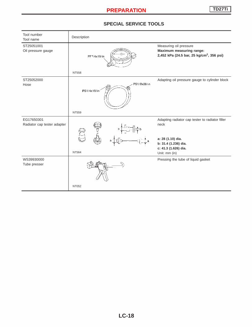
SPECIAL SERVICE TOOLS
Tool numberTool name
Description
ST25051001Oil pressure gauge
NT558
Measuring oil pressureMaximum measuring range:2,452 kPa (24.5 bar, 25 kg/cm 2, 356 psi)
ST25052000Hose
NT559
Adapting oil pressure gauge to cylinder block
EG17650301Radiator cap tester adapter
NT564
Adapting radiator cap tester to radiator fillerneck
a: 28 (1.10) dia.b: 31.4 (1.236) dia.c: 41.3 (1.626) dia.Unit: mm (in)
WS39930000Tube presser
NT052
Pressing the tube of liquid gasket
PREPARATION TD27Ti
LC-18

LIQUID GASKET APPLICATION PROCEDUREa. Before applying liquid gasket, use a scraper to remove all
traces of old liquid gasket from mating surface.b. Apply a continuous bead of liquid gasket to mating sur-
faces.(Use Genuine Liquid Gasket or equivalent.)I Be sure liquid gasket is 3.5 to 4.5 mm (0.138 to 0.177
in) wide (for oil pan).I Be sure liquid gasket is 2.0 to 3.0 mm (0.079 to 0.118
in) wide (in areas except oil pan).c. Apply liquid gasket to inner sealing surface around hole
perimeter area.(Assembly should be done within 5 minutes after coating.)
d. Wait at least 30 minutes before refilling engine oil andengine coolant.
SEM371C
PRECAUTION TD27Ti
LC-19

Lubrication Circuit
ELC037
ENGINE LUBRICATION SYSTEM TD27Ti
LC-20
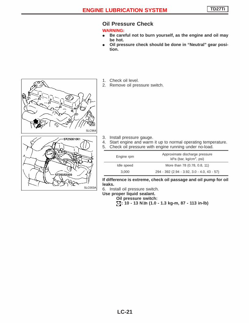
Oil Pressure CheckWARNING:I Be careful not to burn yourself, as the engine and oil may
be hot.I Oil pressure check should be done in “Neutral” gear posi-
tion.
1. Check oil level.2. Remove oil pressure switch.
3. Install pressure gauge.4. Start engine and warm it up to normal operating temperature.5. Check oil pressure with engine running under no-load.
Engine rpmApproximate discharge pressure
kPa (bar, kg/cm2, psi)
Idle speed More than 78 (0.78, 0.8, 11)
3,000 294 - 392 (2.94 - 3.92, 3.0 - 4.0, 43 - 57)
If difference is extreme, check oil passage and oil pump for oilleaks.6. Install oil pressure switch.Use proper liquid sealant.
Oil pressure switch:: 10 - 13 N⋅m (1.0 - 1.3 kg-m, 87 - 113 in-lb)
SLC964
SLC003A
ENGINE LUBRICATION SYSTEM TD27Ti
LC-21

Oil Pump
OIL PUMP INSPECTION1. Inspect pump body, gears and drive shaft for wear and dam-
age.2. Using a feeler gauge and fuse wire, check the following clear-
ances.Gear side clearance:
Less than 0.13 mm (0.0051 in)
Gear backlash:Less than 0.43 mm (0.0169 in)
3. Measure inside diameter “A” of bushing.A: 13.012 - 13.098 mm (0.5123 - 0.5157 in)
MLC128A
SLC966
SLC967
SLC968
ENGINE LUBRICATION SYSTEM TD27Ti
LC-22

4. Measure outside diameter “B” of drive gear shaft.B: 12.974 - 12.992 mm (0.5108 - 0.5115 in)
5. Calculate oil pump bushing clearance.Oil pump bushing clearance (A − B):
Less than 0.15 mm (0.0059 in)
If it exceeds the limit replace oil pump bushing or entire oilpump assembly.
SLC969
NLC057
ENGINE LUBRICATION SYSTEM TD27Ti
Oil Pump (Cont’d)
LC-23

Oil Filter Bracket
q1 O-ringq2 Oil pump relief valve
q3 Oil filterq4 Oil filter bracket
q5 Oil filter relief valveq6 Protection shield
OIL PUMP RELIEF VALVE INSPECTION1. Visually inspect components for wear and damage.2. Coat relief valve with engine oil and check that it falls smoothly
into the valve hole by its own weight.If damaged, replace oil pump relief valve set.
OIL FILTER RELIEF VALVE INSPECTIONInspect oil filter short valve for movement, cracks and breaks bypushing the ball.If damaged, replace oil filter bracket assembly.
NLC056
ENGINE LUBRICATION SYSTEM TD27Ti
LC-24

Oil Cooler
q1 Oil pressure switchq2 Regulator valve
q3 Oil cooler elementq4 Oil filter relief valve
q5 O-ring
OIL COOLER RELIEF VALVE INSPECTIONInspect oil cooler relief valve for movement, cracks and breaks bypushing the ball.If damaged, replace oil cooler relief valve set.
REGULATOR VALVE INSPECTION1. Visually inspect components for wear and damage.2. Coat regulator valve with engine oil and check that it falls
smoothly into the valve hole by its own weight.If damaged, replace regulator valve set.
NLC055
ENGINE LUBRICATION SYSTEM TD27Ti
LC-25

Oil JetINSPECTION (For gear train)Make sure that the holes are not clogged. Clean them with a wireif necessary.
Oil jet has to be installed with oil hole facing crank gear andidler gear.
INSPECTION (For piston)1. Blow through outlet of oil jet and make sure that air comes out
of inlet.2. Push cut-off valve of oil jet bolt with a clean resin or brass rod
and make sure that cut-off valve moves smoothly with properrepulsion.
When installing oil jet, align oil jet’s boss with hole on cylin-der block.
Oil jet bolt:: 29 - 39 N⋅m
(3.0 - 4.0 kg-m, 22 - 29 ft-lb)
Dimension “D”:22 mm (0.87 in)
SLC974
SLC015
SLC975
SLC325A
ENGINE LUBRICATION SYSTEM TD27Ti
LC-26

Cooling Circuit
NLC011
ENGINE COOLING SYSTEM TD27Ti
LC-27

System InspectionCHECKING HOSESCheck hoses for proper attachment, leaks, cracks, damage, looseconnections, chafing and deterioration.
CHECKING RADIATOR CAPTo check radiator cap, apply pressure to the cap with a cap tester.
Radiator cap relief pressure:78 - 98 kPa(0.78 - 0.98 bar, 0.8 - 1.0 kg/cm 2, 11 - 14 psi)
CHECKING COOLING SYSTEM FOR LEAKSAppear pressure to the cooling system by means of a tester tocheck for leakage.
Testing pressure:157 kPa (1.57 bar, 1.6 kg/cm 2, 23 psi)
CAUTION:Higher than the specified pressure may cause radiator dam-age.
SLC613
SMA990A
ENGINE COOLING SYSTEM TD27Ti
LC-28

Water PumpREMOVAL AND INSTALLATIONDrain coolant from drain plugs on cylinder block and radiator.
Cylinder block drain plug:(Use proper sealant)
: 20 - 29 N⋅m (2.0 - 3.0 kg-m, 14 - 22 ft-lb)
CAUTION:I When removing water pump assembly, be careful not to
spill coolant on drive belt.I Water pump cannot be disassembled and should be
replaced as a unit.I Always replace with new gasket.I After installing water pump, connect hose and clamp
securely, then check for leaks using radiator cap tester.
NLC012
NLC058
ENGINE COOLING SYSTEM TD27Ti
LC-29

INSPECTION1. Check for badly rusted or corroded body assembly and vane.
2. Check the water pump bushing for excessive end play andirregular movement.
3. Check fan coupling for rough operation, oil leakage or bentbimetal.
The water pump and fan coupling cannot be disassembled andshould be replaced as a unit.
SLC979
SLC244
SLC245
ENGINE COOLING SYSTEM TD27Ti
Water Pump (Cont’d)
LC-30

Thermostat
q1 Water outletq2 Thermostat with jiggle valveq3 Rubber seal
q4 Water connectorq5 Thermostat housing
q6 Engine coolant temperature sen-sor
q7 Thermal transmitter
CAUTION:I After installation, run engine for a few minutes, and check
for leaks.I Be careful not to spill coolant over engine compartment.
Place a rag to absorb coolant.
INSPECTION1. Check for valve seating condition at ordinary temperatures. It
should seat tightly.2. Check valve opening temperature and maximum valve lift.
Standard type Optional type
Valve opening temperature °C (°F) 82 (180) 88 (190)
Max. valve liftmm/°C (in/°F)
8/95(0.315/203)
8/100(0.315/212)
3. Then check if valve closes at 5°C (9°F) below valve openingtemperature.
NLC059
SLC343
ENGINE COOLING SYSTEM TD27Ti
LC-31

Radiator
CAUTION:When filling radiator with coolant, refer to MA section.
NLC082
ENGINE COOLING SYSTEM TD27Ti
LC-32

Cooling FanDISASSEMBLY AND ASSEMBLY
INSPECTIONCheck fan coupling for irregular operation, oil leakage or bentbimetal.
YLC041
SLC072
ENGINE COOLING SYSTEM TD27Ti
LC-33

Engine Lubrication SystemOil pressure check
Engine rpmApproximate discharge pressure
kPa (bar, kg/cm2, psi)
Idle speed More than 78 (0.78, 0.8, 11)
3,000 294 - 392 (2.94 - 3.92, 3.0 - 4.0, 43 - 57)
Oil pumpUnit: mm (in)
Gear side clearance Less than 0.13 (0.0051)
Gear backlash Less than 0.43 (0.0169)
Oil pump bushing clearance Less than 0.15 (0.0059)
Oil pump bushing inside diameter13.012 - 13.098
(0.5123 - 0.5157)
Drive gear shaft outside diameter12.974 - 12.992
(0.5108 - 0.5115)
Engine Cooling SystemThermostat
Standard type Optional type
Valve opening temperature°C (°F)
82 (180) 88 (190)
Max. Valve liftmm/°C (in/°F)
8/95(0.315/203)
8/100(0.315/212)
RadiatorUnit: kPa (bar, kg/cm2, psi)
Cap relief pressure78 - 98
(0.78 - 0.98, 0.8 - 1.0, 11 - 14)
Leakage test pressure 157 (1.57, 1.6, 23)
SERVICE DATA AND SPECIFICATIONS (SDS) TD27Ti
LC-34